CN101156043A - Swivel bearings in articulated measuring arms - Google Patents
Swivel bearings in articulated measuring armsDownload PDFInfo
- Publication number
- CN101156043A CN101156043ACNA2006800114400ACN200680011440ACN101156043ACN 101156043 ACN101156043 ACN 101156043ACN A2006800114400 ACNA2006800114400 ACN A2006800114400ACN 200680011440 ACN200680011440 ACN 200680011440ACN 101156043 ACN101156043 ACN 101156043A
- Authority
- CN
- China
- Prior art keywords
- measuring machine
- coordinate measuring
- bearings
- housing
- axle
- Prior art date
- Legal status (The legal status is an assumption and is not a legal conclusion. Google has not performed a legal analysis and makes no representation as to the accuracy of the status listed.)
- Granted
Links
Images


Classifications
- G—PHYSICS
- G01—MEASURING; TESTING
- G01B—MEASURING LENGTH, THICKNESS OR SIMILAR LINEAR DIMENSIONS; MEASURING ANGLES; MEASURING AREAS; MEASURING IRREGULARITIES OF SURFACES OR CONTOURS
- G01B5/00—Measuring arrangements characterised by the use of mechanical techniques
- G01B5/004—Measuring arrangements characterised by the use of mechanical techniques for measuring coordinates of points
- G01B5/008—Measuring arrangements characterised by the use of mechanical techniques for measuring coordinates of points using coordinate measuring machines
Landscapes
- Physics & Mathematics (AREA)
- General Physics & Mathematics (AREA)
- Length Measuring Devices With Unspecified Measuring Means (AREA)
- A Measuring Device Byusing Mechanical Method (AREA)
Abstract
Description
Translated fromChinese技术领域technical field
本发明总体上涉及坐标测量机(CMMs)并且特别地涉及一种具有铰接臂的便携式坐标测量机。The present invention relates generally to coordinate measuring machines (CMMs) and in particular to a portable CMM with an articulated arm.
背景技术Background technique
当前,提出了一种作为测量系统的带有主机和应用软件的便携式铰接臂。该铰接臂通常被用于测量一个物体上的一些点,而且这些测量的点被用来与存储在主机中的计算机辅助设计(CAD)数据相比较以便确定这个物体是否处于计算机辅助设计规范之内。换句话说,该CAD数据为参考数据,由铰接臂实际测量的数据与所述参考数据进行比较。主机还可以包括引导操作者进行检验过程的应用软件。在涉及复杂应用的多种情况下,这种安排是合理的,因为使用者将会在对应用软件中的复杂命令作出响应的同时观察到该主机上的三维CAD数据。Currently, a portable articulated arm with a host computer and application software is proposed as a measurement system. The articulated arm is typically used to measure points on an object, and these measured points are compared with computer-aided design (CAD) data stored in a host computer to determine whether the object is within CAD specifications . In other words, this CAD data is reference data with which the data actually measured by the articulated arm is compared. The host computer may also include application software to guide the operator through the inspection process. In many cases involving complex applications, this arrangement makes sense because the user will be viewing the 3D CAD data on the host computer while responding to complex commands in the application software.
美国专利第US5,402,582号(下面简称为第’582号专利)公开了一种用在上述测量系统中的现有的便携式坐标测量机的例子,该专利同样被转让给本发明的受让人,该专利在此以引用的方式结合在本申请中。第’582号专利公开了一种传统的三维测量系统,它由一个人工操作的具有多个关节的铰接臂组成,该铰接臂具有一个位于其一端的支承基座和一个位于其另一端的测量探针。主机通过一个中间控制器或串行盒与铰接臂通信。可以理解的是,在第’582号专利中,铰接臂将会与串行盒进行电子通信,依此地,串行盒与主机进行电子通信。共同转让的美国专利第US5,611,147(下面简称为第‘147号专利)也以引用的方式结合在本申请中,该第专利‘147号专利公开了一种相似的具有铰接臂的坐标测量机。在该专利中,铰接臂包括许多重要的特征,这些重要的特征包括在探针末端处的一个附加的旋转轴,从而为一个臂提供一种2-1-3(two-one-three)或一个2-2-3(two-two-three)关节结构(后一种情况是一个7轴臂)以及用于该臂中的轴承的改进的预加载荷轴承结构。U.S. Patent No. 5,402,582 (hereinafter referred to as the '582 patent) discloses an example of a conventional portable coordinate measuring machine used in the above-mentioned measurement system, which patent is also assigned to the assignee of the present invention , which is hereby incorporated by reference into this application. The '582 patent discloses a conventional three-dimensional measurement system consisting of a manually operated articulated arm with a support base at one end and a measuring probe. The host computer communicates with the articulated arm through an intermediate controller or serial box. It will be appreciated that in the '582 patent, the articulated arm would be in electronic communication with the serial box, which in turn would be in electronic communication with the host computer. Commonly assigned U.S. Patent No. US 5,611,147 (hereinafter referred to as the '147 patent), also incorporated herein by reference, discloses a similar coordinate measuring machine with an articulated arm . In this patent, the articulated arm includes a number of important features, including an additional axis of rotation at the end of the probe, thereby providing an arm with a 2-1-3 (two-one-three) or A 2-2-3 (two-two-three) joint structure (in the latter case a 7-axis arm) and an improved preloaded bearing structure for the bearings in the arm.
其它相关的现有坐标测量机还包括共同转让的美国专利第US5,926,782(下面简称为第‘782号专利),该专利提供了一种铰接臂,该铰接臂具有可锁定的转换壳体,以便消除一个或多个自由度;以及美国专利第US5,956,857(下面简称为第‘857号),该专利提供了一种铰接臂,该铰接臂具有一种快速拆开的安装系统。Other related prior coordinate measuring machines include commonly assigned US Patent No. US 5,926,782 (hereinafter referred to as the '782 patent), which provides an articulated arm having a lockable transition housing, so as to eliminate one or more degrees of freedom; and US Patent No. 5,956,857 (hereinafter referred to simply as '857), which provides an articulated arm with a quick release mounting system.
在此描述的更多现有类型的便携式坐标测量机都不是必须采用一个中间控制器或串行盒,因为现在它的功能被结合在主机所提供的软件中。例如,共同转让的美国专利第US5,978,748号(下面简称第‘748号专利),在此以引用的方式结合在本申请中,公开了一种具有一个在板控制器的铰接臂,该在板控制器存储有一个或多个可执行的程序并且为使用者提供指令(例如检验程序)以及储存作为参考数据的CAD数据。在第专利‘748号专利中,一个控制器被安装到铰接臂上并运行可执行的程序,该可执行程序指导使用者经过例如检验程序的过程。在这样一种系统中,主机可以用来生成可执行的程序。安装到铰接臂上的控制器用来运行可执行的程序但不能用来产生可执行的程序或更改可执行的程序。通过模拟视频游戏系统,主机用作书写或更改视频游戏的平台而且安装到臂上的控制器用作玩视频游戏的平台。控制器(例如,玩游戏的人)不能更改可执行的程序。如在第‘748号专利中所述,通过消除每个铰接臂都需要一台主机的需求,因此获得了一种低成本的三维坐标测量系统。转让给本申请的受让人且通过引用方式结合在本申请中的美国专利申请第09/775,236号(下面简称为第‘236申请)公开了一种用于向第‘748号专利中公开的坐标测量系统的使用者发送可执行的程序的方法和系统。该方法包括接收用户要求生成一个可执行的程序的请求并获得与该可执行程序相关的信息。然后产生指导操作者经过一些测量步骤的可执行的程序,所述一些测量步骤是通过三维坐标测量系统来执行。所述可执行的程序被传送到用户,优选为通过在线网络比如互联网传送。More existing types of portable CMMs described here do not necessarily employ an intermediate controller or serial box, since its functionality is now incorporated in the software provided by the host computer. For example, commonly assigned U.S. Patent No. US 5,978,748 (hereinafter referred to as the '748 patent), which is incorporated herein by reference, discloses an articulated arm with an on-board controller that The panel controller stores one or more executable programs and provides instructions to the user (eg inspection programs) and stores CAD data as reference data. In the '748 patent, a controller is mounted to the articulated arm and runs an executable program that guides the user through a process such as an inspection procedure. In such a system, the host computer can be used to generate executable programs. The controller mounted on the articulating arm is used to run the executable program but cannot be used to create the executable program or change the executable program. By simulating a video game system, the main unit serves as a platform for writing or altering the video game and the controller mounted to the arm serves as a platform for playing the video game. A controller (eg, a human playing a game) cannot change executable programs. By eliminating the need for a mainframe for each articulated arm, as described in the '748 patent, a low cost three-dimensional coordinate measurement system is thus obtained. U.S. Patent Application No. 09/775,236 (hereinafter referred to as the '236 application), assigned to the assignee of the present application and incorporated herein by reference, discloses a A method and system for delivering an executable program to a user of a coordinate measurement system. The method includes receiving a user's request to generate an executable program and obtaining information related to the executable program. An executable program is then generated that guides the operator through the measurement steps performed by the three-dimensional coordinate measuring system. The executable program is delivered to the user, preferably over an online network such as the Internet.
共同转让的美国专利第US6,131,2996号(下面简称为第‘299号专利,其所有内容都通过引用方式结合在本申请中),公开了一种其上布置有一个显示装置的铰接臂,该显示装置使操作者能够获得位置数据的方便显示和系统菜单提示。该显示装置包括例如LED,所述LED指示系统电源、转换器位置情况和出错情况。转让给本申请的受让人并通过引用方式结合在本申请中的美国专利第US6,219,928号(下面简称为第‘928号专利)公开了一种用于铰接臂的串行网络。该串行网络传将位于该铰接臂中的转换器的数据传送到一个控制器。每个转换器包括一带有存储器的转换器接口,该存储器储存转换器数据。该控制器对每个存储器进行串行寻址且数据从转换器接口存储器被传送到控制器。共同转让的美国专利第US6,253,458(下面简称为第‘458号专利)以及US6,298,569(下面简称为第‘569号专利)都公开了用于在此所描述的铰接臂便携式坐标测量机的可调节的平衡机构。Commonly assigned U.S. Patent No. US 6,131,2996 (hereinafter referred to as the '299 patent, the entire contents of which are incorporated herein by reference), discloses an articulated arm on which a display device is disposed , the display device enables the operator to obtain a convenient display of position data and system menu prompts. The display means includes, for example, LEDs that indicate system power, converter position conditions and error conditions. U.S. Patent No. 6,219,928 (hereinafter referred to as the '928 patent), assigned to the assignee of the present application and incorporated herein by reference, discloses a serial network for an articulated arm. The serial network transmits data from the converter located in the articulated arm to a controller. Each converter includes a converter interface with memory that stores converter data. The controller addresses each memory serially and data is transferred from the converter interface memory to the controller. Commonly assigned U.S. Patent Nos. US 6,253,458 (hereinafter referred to as the '458 patent) and US 6,298,569 (hereinafter referred to as the '569 patent) both disclose methods for use in the articulating arm portable coordinate measuring machine described herein. Adjustable balance mechanism.
尽管这些技术方案都能很好地适用于其所实现的目的,但是在该行业一直存在需要改进的便携式坐标测量机的需求,该改进的坐标测量机易于使用、制造效率更高、提供改进的特征且售价较低。While these technical solutions are well suited for the purposes they serve, there is a continuing need in the industry for an improved portable coordinate measuring machine that is easy to use, more efficient to manufacture, provides improved features and a lower price.
发明内容Contents of the invention
根据本发明的一种便携式CMM包括一个铰接臂,该铰接臂具有连接的臂段。在一个实施例中,这些臂段包括轴承/编码器机芯,这些轴承/编码器机芯采用一种双套筒接头以预定的角度彼此连接起来。每个机芯都包括至少一个,优选为两个,预加载荷轴承组件以及一个编码器,优选是光学编码器,它们都组装在一个圆柱形壳体中。优选的是,在每个接头中都采用两个或多个编码器读出头,以促成能够进行求平均值的抵消效应。所述臂段可以通过螺纹连接的方式相互连接起来,臂从基部处的直径较大的部分逐渐探针端部处的直径较小的部分变细。A portable CMM according to the present invention includes an articulated arm having attached arm segments. In one embodiment, the arm segments include bearing/encoder cores connected to each other at predetermined angles using a double sleeve joint. Each movement includes at least one, preferably two, preloaded bearing assemblies and an encoder, preferably an optical encoder, all assembled in a cylindrical housing. Preferably, two or more encoder read heads are employed in each joint to facilitate a canceling effect enabling averaging. The arm segments may be interconnected by threaded connections, the arms tapering from a larger diameter portion at the base to a smaller diameter portion at the probe end.
根据本发明的另一个实施例,铰接臂的连接的臂段中的一个或多个包括可替换保护壳体和/或缓冲件,用来限制大的冲击和磨损以及用来提供一种符合人体工程学且具有美感和舒适的抓握部位。According to another embodiment of the invention, one or more of the connected arm segments of the articulated arm include replaceable protective shells and/or buffers for limiting large impacts and wear and for providing an anatomical fit. Ergonomic yet aesthetically pleasing and comfortable grip.
在本发明的另一个实施例中,铰接臂包括一个位于其中一个铰接关节内的一体的内部平衡部件。该平衡部件采用了一种螺旋弹簧,该螺旋弹簧具有由金属圆柱体机加工形成的相对较宽的端部环和较窄的内部环。该弹簧还包括至少两个(优选是三个)柱,用于锁定到铰接臂的铰链结构以及一个弹簧调节机构。In another embodiment of the invention, the articulated arm includes an integral internal balancing member within one of the articulated joints. The counterweight employs a helical spring having a relatively wide end ring and a narrow inner ring machined from a metal cylinder. The spring also includes at least two (preferably three) posts, a hinge structure for locking to the articulated arm, and a spring adjustment mechanism.
在本发明的另一个实施例中,铰接臂包括一个位于其端部的测量探针。该测量探针具有一个一体安装的接触触发器探针,该接触触发器探针可以容易地转换成一个传统的硬探针。测量探针还包括一些改进的开关以及一个测量指示灯。在一个实施例中,这些开关具有弧形的椭圆形形状并且能够容易地由操作者驱动。这些改进的开关具有不同的颜色、表面纹路和/或高度,以便操作者能够容易地对它们进行区分,同时指示灯优选为用不同颜色标记(color-coded),以便于操作。In another embodiment of the invention, the articulated arm includes a measuring probe at its end. The measurement probe has an integrally mounted contact trigger probe that can be easily converted to a conventional hard probe. The measurement probe also includes improved switches and a measurement indicator light. In one embodiment, the switches have a curved oval shape and can be easily actuated by an operator. These improved switches have different colors, surface textures and/or heights so that operators can easily distinguish them, while the indicator lights are preferably color-coded for ease of operation.
本发明的另一个实施例包括一个铰接臂,该铰接臂具有一个一体的、在板的电源可再充电单元。该电源/可再充电单元使得CMM能实现充分的便携功能并且使得能够很方便地在偏远的位置和/或在不需要电缆直接连接的铰接臂的情况下使用CMM。Another embodiment of the present invention includes an articulated arm with an integral, on-board power rechargeable unit. The power supply/rechargeable unit enables the CMM to be fully portable and to facilitate the use of the CMM in remote locations and/or without the need for an articulating arm directly connected by a cable.
本发明的另一个实施例包括一个铰接臂,该铰接臂在其一端具有一个测量探针。该测量探针包括一个可旋转的手柄壳体和开关组件,该开关组件包围着测量探针。可旋转的手柄壳体和开关组件使得测量探针可以更容易地把持和驱动而不需考虑手的位置。使用可旋转的手柄壳体还消除了在探针末端具备第三旋转轴的需要,因此获得一种成本较低且结构更简单的便携式CMM(相对于7轴的CMM或在测量探针处具有第三旋转角度的CMM而言)。Another embodiment of the invention includes an articulated arm having a measurement probe at one end thereof. The measuring probe includes a rotatable handle housing and a switch assembly surrounding the measuring probe. The rotatable handle housing and switch assembly make it easier to hold and drive the measuring probe regardless of hand position. Using a rotatable handle housing also eliminates the need for a third axis of rotation at the probe end, thus resulting in a less expensive and simpler portable CMM (compared to a 7-axis CMM or having a For CMMs with a third rotation angle).
在本发明的另一个实施例中,一个便携式CMM包括一个铰接臂,该铰接臂具有连接起来的臂段,在铰接臂的一端具有一个测量探针而在其另一端具有一个基座。根据该实施例的一个新颖的特征,基座中具有一个一体的磁性安装件,用于将铰接臂固定到一个磁性表面。该一体的磁性安装件优选是采用螺纹连接方式连接到铰接臂上并且具有一个开/关(on/off)控制杆以方便使用(优选地,该控制杆在安装件安置在一个磁性表面上时自动配合)。In another embodiment of the invention, a portable CMM includes an articulated arm having joined arm segments with a measurement probe at one end of the articulated arm and a base at its other end. According to a novel feature of this embodiment, there is an integral magnetic mount in the base for securing the articulating arm to a magnetic surface. The integral magnetic mount is preferably threaded onto the articulating arm and has an on/off lever for ease of use (preferably, the lever is automatically fit).
本领域的技术人员将能够根据下面的详细说明和附图理解和认识本发明的上述的以及其它的优点和特征。Those skilled in the art will be able to understand and appreciate the above-mentioned and other advantages and features of the present invention from the following detailed description and accompanying drawings.
附图说明Description of drawings
现在参见附图,其中在附图中相同的元件采用相同的数字标记。Referring now to the drawings, wherein like elements are labeled with like numerals throughout.
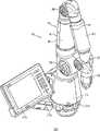
图1是本发明的便携式CMM的前视立体图,其包括一个铰接臂以及相连的主机;Fig. 1 is the front perspective view of portable CMM of the present invention, and it comprises an articulated arm and connected main frame;
图2是图1中的CMM的后视立体图;Figure 2 is a rear perspective view of the CMM in Figure 1;
图3是图1中的CMM的右侧视图(其中主机被移除);Fig. 3 is the right side view of the CMM in Fig. 1 (wherein main frame is removed);
图3A是图1中的CMM的右侧视图,其中覆盖两个长关节的保护套略有改变;Figure 3A is a right side view of the CMM in Figure 1 with the protective sleeve covering the two long joints slightly altered;
图4是本发明的CMM的局部分解立体图,其中示出了基座和第一铰接臂部分;Figure 4 is a partial exploded perspective view of the CMM of the present invention showing the base and first articulating arm portion;
图5是本发明的CMM的局部分解立体图,其中示出了基座、第一臂部分以及局部分解的第二臂部分;5 is a partially exploded perspective view of the CMM of the present invention showing the base, first arm portion, and partially exploded second arm portion;
图6是本发明的CMM的局部分解立体图,其中示出了基座、第一臂部分、第二臂部分以及局部分解的第三臂部分;6 is a partially exploded perspective view of the CMM of the present invention, showing a base, a first arm portion, a second arm portion, and a partially exploded third arm portion;
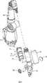
图7是一个分解立体图,其中示出了一对本发明的编码器/轴承机芯,其组装在两个双套筒接头之间;Figure 7 is an exploded perspective view showing a pair of encoder/bearing cores of the present invention assembled between two double sleeve joints;
图8是图7中所示的的轴承/编码器机芯和双套筒接头的前视正面图;Figure 8 is a front elevational view of the bearing/encoder core and double sleeve joint shown in Figure 7;
图9是本发明的短轴承/编码器机芯的分解立体图;Fig. 9 is an exploded perspective view of the short bearing/encoder movement of the present invention;
图9A是与图9相似的分解立体图,不同的是示出了单个读出头;Figure 9A is an exploded perspective view similar to Figure 9, but showing a single read head;
图9B是与图9相似的分解立体图,不同的是示出了四个读出头;Figure 9B is an exploded perspective view similar to Figure 9, except that four read heads are shown;
图9C是图9B组装后的立体图;Figure 9C is a perspective view of Figure 9B assembled;
图9D是与图9相似的分解立体图,不同的是示出了三个读出头;Figure 9D is an exploded perspective view similar to Figure 9, except that three read heads are shown;
图9E是图9D组装后的立体图;Figure 9E is a perspective view of Figure 9D assembled;
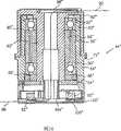
图10是图9中所示机芯的剖视图;Figure 10 is a sectional view of the movement shown in Figure 9;
图11是本发明的长轴承/编码器机芯的分解立体图;Fig. 11 is an exploded perspective view of the long bearing/encoder movement of the present invention;
图11A是与图11相似的分解立体图,不同的是示出了单个读出头;Figure 11A is an exploded perspective view similar to Figure 11, but showing a single read head;
图12是图11中所示机芯的剖视图;Figure 12 is a sectional view of the movement shown in Figure 11;
图12A是图12中所示的机芯剖视图,示出了可与轴一起旋转的双读出头;Figure 12A is a cross-sectional view of the movement shown in Figure 12 showing the dual readheads rotatable with the shaft;
图13是本发明另一个轴承/编码器机芯的分解立体图;Fig. 13 is an exploded perspective view of another bearing/encoder movement of the present invention;
图13A是与图13相似的分解立体图,不同的是示出了单个读出头;Figure 13A is an exploded perspective view similar to Figure 13, but showing a single read head;
图14是图13中所示机芯的剖视图;Figure 14 is a cross-sectional view of the movement shown in Figure 13;
图15是本发明一个轴承/编码器机芯以及平衡弹簧的分解立体图;Fig. 15 is an exploded perspective view of a bearing/encoder movement and a balance spring of the present invention;
图15A是与图15相似的分解立体图,不同的是示出了单个读出头;Figure 15A is an exploded perspective view similar to Figure 15, but showing a single read head;
图16是图15中所示机芯和平衡部件的剖视图;Figure 16 is a cross-sectional view of the movement and balance components shown in Figure 15;
图17是用于本发明的一种直径较大的轴承/编码器机芯的双读出头组件的俯视图;Figure 17 is a top view of a dual readhead assembly for a larger diameter bearing/encoder movement of the present invention;
图18所示的是沿图17中的18-18方向的剖视图;What Fig. 18 shows is the sectional view along the 18-18 direction in Fig. 17;
图19所示的是图17中所示的双读出头组件的仰视图;Figure 19 is a bottom view of the dual read head assembly shown in Figure 17;
图20所示的是用于本发明的直径较小的轴承/编码器机芯的双读出头组件的俯视图;Figure 20 is a top view of a dual readhead assembly for a smaller diameter bearing/encoder core of the present invention;
图21所示的是沿图20中的21-21方向的剖视图;What Figure 21 shows is a sectional view along the direction 21-21 in Figure 20;
图22所示的是图20中所示的双读出头组件的仰视图;Figure 22 is a bottom view of the dual read head assembly shown in Figure 20;
图23A是本发明的使用单读出头的CMM所采用的电子器件构造的方框图;图23B是本发明的使用双读出头的CMM所采用的电子器件构造的方框图;Fig. 23A is a block diagram of the electronic device structure adopted by the CMM using a single read head of the present invention; Fig. 23B is a block diagram of the electronic device structure adopted by the CMM using dual read heads of the present invention;
图24所示的是本发明CMM的纵向剖视图(其中移除了基座);What Fig. 24 shows is the longitudinal sectional view of CMM of the present invention (wherein removed base);
图24A所示的是图3A中所示的CMM的剖视图;Figure 24A is a cross-sectional view of the CMM shown in Figure 3A;
图25所示的是图24中的一部分的放大剖视图,示出了图24中的CMM的基座以及第一长关节段;Figure 25 is an enlarged cross-sectional view of a part of Figure 24, showing the base of the CMM in Figure 24 and the first long joint segment;
图25A是表示根据本发明的另一个实施例的长关节和短关节之间相互连接的立体图;Fig. 25A is a perspective view showing the interconnection between long joints and short joints according to another embodiment of the present invention;
图25B所示的是图25A中的一部分的纵向剖视图;What Fig. 25 B shows is the longitudinal sectional view of a part in Fig. 25 A;
图26所示的是图24中的一部分的放大剖视图,示出了第二和第三长关节段;Figure 26 is an enlarged cross-sectional view of a portion of Figure 24 showing the second and third long joint segments;
图26A和B所示的是图24A中的一部分的放大剖视图,示出了第二和第三长关节以及探针;Figures 26A and B are enlarged cross-sectional views of a portion of Figure 24A showing second and third long joints and a probe;
图27A所示的是一个分解侧视图,示出了本发明的第一短关节/平衡组件;Figure 27A is an exploded side view showing the first short joint/balance assembly of the present invention;
图27B是表示出图27A中的元件的立体图;Figure 27B is a perspective view showing the elements in Figure 27A;
图28是表示本发明的内部平衡部件的剖视图;Fig. 28 is a cross-sectional view showing an internal balance member of the present invention;
图29是本发明测量探针的第一实施例的侧向剖视图;Figure 29 is a side sectional view of the first embodiment of the measuring probe of the present invention;
图29A是本发明测量探针的另一个实施例的侧视图;Figure 29A is a side view of another embodiment of the measurement probe of the present invention;
图29B是沿图29A中的29B-29B方向的剖视图;Figure 29B is a cross-sectional view along the direction 29B-29B in Figure 29A;
图29C是用于图29A-B中的一对“执行”或“确认”开关的立体图;Figure 29C is a perspective view of a pair of "go" or "confirm" switches used in Figures 29A-B;
图30A-C是表示本发明的一体的接触探针组件以及转换成硬探针组件的连续的平面视图;30A-C are sequential plan views illustrating the integrated contact probe assembly of the present invention and conversion to a rigid probe assembly;
图31是本发明的测量探针的另一个实施例的侧剖面视图;Figure 31 is a side sectional view of another embodiment of the measurement probe of the present invention;
图32是本发明的一体的磁性基座的分解立体图;Fig. 32 is an exploded perspective view of the integrated magnetic base of the present invention;
图33是图32中的磁性基座的剖视图;Figure 33 is a cross-sectional view of the magnetic base in Figure 32;
图34是图32中的磁性安装件的俯视图;Figure 34 is a top view of the magnetic mount in Figure 32;
图35是来自于Raab的美国专利第US5,794,356号的具有双读出头的CMM接头的剖视图;Figure 35 is a cross-sectional view of a CMM adapter with dual read heads from U.S. Patent No. 5,794,356 to Raab;
图36是来自于Eaton的美国专利第US5,829,148号的具有双读出头的CMM接头的剖视图;Figure 36 is a cross-sectional view of a CMM connector with dual read heads from U.S. Patent No. 5,829,148 to Eaton;
图37是具有第七轴转换器的测量探针的侧视图;Figure 37 is a side view of a measurement probe with a seventh axis transducer;
图38是与图37类似的侧视图,不同的是其包括一个可拆卸的手柄;Figure 38 is a side view similar to Figure 37, except that it includes a removable handle;
图39是图38中的测量探针的端部视图;Figure 39 is an end view of the measurement probe of Figure 38;
图40是图38中的测量探针的剖视图;及Figure 40 is a cross-sectional view of the measurement probe in Figure 38; and
图41、42和43是可供选择的机芯结构的剖视图。Figures 41, 42 and 43 are cross-sectional views of alternative movement constructions.
具体实施方式Detailed ways
参见图1-3,本发明的CMM总体上采用标记10表示,CMM10包括一个多关节连接的(multijointed)、手工操作的铰接臂14,该铰接臂在一端连接到基座部分12上,而在另一端连接到一个测量探针28上。臂14基本上由两种类型的关节(joint)构成,即长关节(用于回转运动)以及短关节(用于铰接运动)。该长关节基本上沿着臂的轴向或纵向方向布置,而短关节则优选为相对于臂的纵向轴线成90度布置。该长关节和短关节配对出现,这种关节的配对构造通常称之为2-2-2(尽管也可以采用其它的关节的构造形式,例如2-1-2,2-1-3,2-23等)。图4-6中示出了这些关节对中的每一对。Referring to FIGS. 1-3, the CMM of the present invention is generally indicated by
图4示出了第一关节对的分解视图,即长关节16和短关节18。图4还示出了基座12的分解视图,其包括便携式电源电子器件20、便携式电池组22、磁性安装件24以及两件式基座壳体26A和26B。所有这些元件都会在下面进行更详细的描述。FIG. 4 shows an exploded view of the first joint pair, the long joint 16 and the short joint 18 . 4 also shows an exploded view of
重要的是,需要理解的是,铰接臂14的各种主要部件的直径都是从基座12到探针28逐渐变细。这种逐渐变细的过程是连续的,或者如在图中的实施例所示,这种逐渐变细可以是不连续的或者是阶梯方式。此外,铰接臂14的每个主要部件都可以通过螺纹连接的方式进行连接,借此消除现有CMM所涉及到的大量的紧固件。例如,象在后面要阐述的那样,磁性安装件24可以采用螺纹连接方式连接到第一长关节16上。优选的是,这种螺纹是锥形螺纹,它可以进行自我锁定并且可以增加轴向/弯曲刚度。供选择地,如图25A和25B所示,象在后面要讨论的那样,铰接臂的主要部件可以具有互补的锥形凸凹端部,这些端部具有相应的凸缘,这种凸缘通过螺栓连接在一起。It is important to understand that the diameters of the various major components of the articulating
参见图5,所示的第二组长关节和短关节连接在所述第一组长关节和短关节上。第二关节组包括长关节30和短关节32。和将磁性安装件24安装到长关节16上一样,长关节30可以通过螺纹连接方式连接到长关节16的内表面的螺纹上。类似地,参见图6,第三关节组包括第三长关节34和第三短关节36。第三长关节34可以通过螺纹连接方式连接到第二短关节32的内表面的螺纹上。象下面将要详细描述的那样,探针28可以通过螺纹连接方式连接到短关节36上。Referring to FIG. 5 , the second group of long and short joints shown is connected to the first group of long and short joints. The second joint group includes
优选的是,每个短关节18、32和36都由铸造和/或机械加工过的铝质元件构成,或者供选择地,采用轻质刚性合金或合成物构成。每个长关节16、30以及34优选都由铸造和/或机械加工过的铝、轻质刚性合金和/或纤维加强聚合物构成。三对前述关节对的机械轴(即第一对包括关节对16、18,第二对包括关节对30、32,第三对包括关节对34、36)相对于该基座对齐以便获得平滑一致的机械特性。前面所述的从基座12到探针28的逐渐变细的结构为优选,以便能够增加在负载较大的基座处的刚度且在通畅使用方面很重要的探针或手柄处的截面较小。如在后面将详细描述的那样,每个短关节的两端上都装有缓冲件38,而每个长关节上都罩有一个保护壳体40或41。需要理解的是,第一长关节16受到基座壳体26A、26B的保护,该基座壳体所提供的保护和保护壳体40、41为第二和第三长关节30、34所提供的保扩类型相同。Preferably, each short joint 18, 32 and 36 is constructed of cast and/or machined aluminum elements, or alternatively, a lightweight rigid alloy or composite. Each long joint 16, 30, and 34 is preferably constructed of cast and/or machined aluminum, lightweight rigid alloy, and/or fiber reinforced polymer. The mechanical axes of the three aforementioned pairs of joints (i.e. the first pair comprising
根据本发明的一个重要特征,铰接臂的每个关节都采用一种模制的(modular)轴承/编码器机芯,例如如图7和8所示的短机芯42以及长机芯44。这些机芯42、44安装在双套筒接头46、48的开口中。每个套筒接头46、48都包括具有第一凹部或套筒120的第一圆柱延伸部分47以及具有第二凹部或套筒51的第二圆柱延伸部分49。通常,套筒120和51彼此成90度角,尽管也可以采用其它相对的角结构。短机芯42布置在双套筒接头46和48的每个套筒51中以构成一种铰链连接(hinge joint),同时长机芯44布置在接头46(见图25)的套筒120中且长机芯44’(见图26)布置在接头48的套筒120中,从而每个都构成一种纵向的回转连接(swivel joint)。模制的轴承/编码器机芯42、44许可单独制造其上安装有模制的编码器元件的预应力或预加载荷的双轴承机芯。该轴承编码器机芯随后可以固定安装到铰接臂14的外部轮廓部件(即,双套筒接头46,48)上。采用这种机芯的显著优点在于它能够高质量高速地生产铰接臂14的这些复杂精密的子部件。According to an important feature of the invention, each joint of the articulated arm employs a modular bearing/encoder core, such as the
在此处所述的实施例中,有四个不同的机芯类型,即,用于关节30、34的两个长轴向机芯、一个用于关节16的基座轴向机芯、一个用于短关节18的基座机芯(其包括一平衡部件)以及两个用于关节32和36的铰接机芯。此外,与逐渐变细的铰接臂14相一致,最靠近基座的机芯(例如,位于长关节16和短关节18中的机芯)的直径相对于具有较小直径的关节30、32、34以及36而言要大些。每个机芯都包括一预加载荷轴承结构和一转换器,在该实施例中,该转换器包括一个数字编码器。参见图9和10,现在对位于轴向长关节16中的机芯44进行说明。In the embodiment described here, there are four different movement types, namely two long axial movements for the
机芯44包括一对由内套筒54和外套筒56分开的轴承50、52。重要的是,轴承50、52是预加载荷的。在该实施例中,这种预加载荷由套筒54、56提供,该套筒54、56具有不同的长度(内套筒54比外套筒56短大约0.0005英寸),因而在紧固时,在轴承50、52上产生一个预先选定的预加载荷。在该组件可旋转地安装在轴60上时,轴承50、52采用密封件58进行密封。在其上表面处,轴60终止于一个轴上部壳体62。在轴60和轴上部壳体62之间形成一个环形空间63。整个组件被布置在外部机芯壳体64内,其中采用内螺母66和外螺母68的组合将该轴60和其轴承组件牢固地安装到外部机芯壳体64上。需要注意的是,在组装的时候,外壳体64的上部65将被收容在环形空间63内。可以理解的是,在对内外螺母66和68进行紧固时压缩力被施加到轴承50、52上,并且由于内衬套54、56的长度不同,将会施加所需的预加载荷,从而将上述预加载荷施加到轴承50、52上。The
优选的,轴承50、52是成对双联向心推力球轴承。为了获得足够的预加载荷,使轴承支承面尽可能的平行是很重要的。该平行度会影响到轴承周边上的预加载荷的均匀度。不均匀的载荷会导致极为不均匀的转矩感觉并且会导致不可预测的径向跳动(radial run out)和降低的编码器性能。模块化安装的编码器盘(将在下面进行讨论)的径向跳动会在读出头下面导致一种不希望有的干涉条纹图案(fringepattern)移位。这种情况会导致非常大的编码器角度测量误差。而且,这种优选的成对双联向心推力球轴承结构的刚度也与轴承的间隔(separation)直接相关。轴承相距越远,组件的刚性越大。衬套54、56用于增强轴承的间隔。由于机芯壳体64优选为铝质的,因此衬套54、56也优选采用铝制成并且在长度和平行度方面进行精确加工。因此,温度改变不会导致不均匀的膨胀,不均匀的膨胀会影响到预加载荷。如前所述,通过在衬套54、56的长度上设计一个已知的差别来设置预加载荷。一旦该螺母66、68被充分地紧固后.该长度差将会导致一个轴承预加载荷。使用密封件58提供密封的轴承,因为轴承的任何污染都会影响到所有旋转运动和编码器的精度以及关节感觉(jointfeel)。Preferably, the
尽管机芯44优选包括一对间隔开的轴承。供选择地,机芯44也可以包括单个轴承或三个或更多的轴承。因此,每个机芯至少需要一个轴承,作为最低需要。Although
本发明的连接机芯既可以作无限的旋转运动,或者供选择地,也可以作有限的旋转运动。对于有限的旋转运动,在壳体64的外表面上的一个凸缘72上的一个槽70形成了一条收容一个梭子(shuttle)74的圆柱轨道70。该梭子74将行驶在轨道70中直到其抵靠一个可拆卸的梭子止动件为止,该梭子止动件例如旋转止动固定螺钉76,该固定螺钉将阻止旋转运动。旋转运动的量可以根据需要进行改变。在一个优选实施例中,梭子的旋转将被限制为小于720度。此处的旋转梭子止动件的类型在共同转让的美国专利第US5,611,147号中有详细的描述,该专利的所有内容已经通过引用的方式结合在本申请中。The linkage movement of the present invention is capable of either infinite rotational movement or, alternatively, limited rotational movement. A
如上所述,在另一个供选择的实施例中,本发明所使用的关节可以进行无限的旋转运动。在该后面一种情况下,采用了一种已知的滑环组件。优选的是,轴60有一个中空或轴向的孔78,该孔的一端有一个直径较大的部分80。在轴向孔78和80之间形成的肩部上抵靠有一个圆柱形滑环组件82。相对于设置在模制的连接机芯中的预加载荷轴承组件而言,滑环组件82是不起结构作用的(也就是说,它并不提供任何机械功能,仅仅提供电的和/或信号传递功能)。尽管滑环组件82可以由商业上可以获得的任何滑环组成,但是在一个优选实施例中,滑环组件82包括可以从英国贝克郡里丁市的IDM电子有限公司获得的H系列滑环。这种滑环尺寸比较紧凑并且具有圆柱形结构,而且可以完美地适用在轴60内的孔80中。穿过轴60的轴向孔80终止于一个孔口84,该孔口84与一个槽道86连通,该槽道86的大小和结构设计用于收容来自于滑环组件82的电线。该电线由电线盖88固定在位并保护,该电线盖88卡装并收容在槽道86和孔口84中。这种电线由图10中的标记90示意性地表示。As noted above, in an alternative embodiment, the joints used in the present invention are capable of infinite rotational motion. In this latter case, a known slip ring assembly is used. Preferably,
如上所述,模制机芯44包括一个上述的预加载荷轴承构件以及一个下面将要描述的模制的编码器构件。还是参见图9和10,用于本发明的优选的转换器包括一个模制光学编码器,该编码器具有两中主要部件,即读出头92和光栅盘94。在该实施例中,一对读出头92布置在一个读出头连接器板96上。该连接器板96安装到(通过紧固件98)一个安装板100上。光栅盘94优选安装(优选采用一种适当的粘合剂)在轴60的下部支承表而102上并且与读出头92(该读出头由板100支承和固定)间隔开并且与读出头对齐。一电线箍104和密封盖106为壳体64的下端提供了最外部的遮盖。电线箍104会如图10所示的那样捕获和保持电线90。可以理解的是,该编码器盘94由102上的粘合剂被固定在轴60上并可随着该轴旋转。图9和10示出了一种双读出头92,不过,可以理解的是,可以使用两个以上的读出头,或者供选择地,可以使用如图9A中所示的单个读出头。图9B-E示出了具有两个以上读出头的模制机芯44的例子。图9B-C示出了安装在一个板100上并且以90度的间隔间隔开(尽管采用不同的相对间隔也是合适的)的四个读出头92。图9D-E表示出了安装在一个板100上并且以120度的间隔间隔开(尽管采用不同的相对间隔也是合适的)的三个读出头92。As noted above, the molded
为了正确地对齐盘94,在靠近盘94的位置提供了一个穿过壳体64的孔(未示出)。随后采用一种工具(未示出)将盘94推动到正确的对齐位置,在该位置上使盘94和轴60之间的粘合剂固化以便将盘94锁定在位。随后将一个孔塞73插入壳体64中的所述孔中。In order to properly align the
重要的是需要指出,该盘94和读出头92的位置可以反过来,从而盘94固定在壳体56上而读出头92与轴60一起旋转。图12A中示出了这样的实施例,其中板96’(通过粘合剂)连接到轴60’上以便与其一起旋转。一对读出头92’连接到板96’上并因此和轴60’一起旋转。盘94’布置在一个支承件100’上,该支承件100’连接到壳体64’上。在任何情况下,可以理解的是,无论是盘94还是读出头92都可以安装成与轴一起旋转。重要的是盘94和读出头92布置在一个机芯(或接头)中以便在维持光通信的同时可以相对于彼此旋转。It is important to note that the positions of the
优选的是,在本发明中所采用的旋转的编码器类似于美国专利第US5,486,923号以及第US5,559,600中披露的旋转的编码器,这两件专利的所有内容通过引用的方式结合在本申请中。这种模制的编码器可以从MicroE Systems公司购买到,其商品名称为Pure PrecisionOptics。这些编码器基于物理光学,该物理光学检测衍射级(diffraction orders)之间的干涉,从而从一个插入干涉条纹图案(fringe pattern)中的图像检测器阵列(例如读出头)生成近乎完美的正弦信号。对该正弦信号进行电子学方法地内插值以便能够检测到仅仅一小部分光学条纹的位移。Preferably, the rotary encoder employed in the present invention is similar to the rotary encoders disclosed in US Pat. Nos. 5,486,923 and 5,559,600, the entire contents of which are incorporated by reference in In this application. Such molded encoders are commercially available from MicroE Systems under the trade name Pure Precision Optics. These encoders are based on physical optics that detect the interference between diffraction orders to generate a near-perfect sinusoidal signal from an array of image detectors (such as a read head) inserted in a fringe pattern . The sinusoidal signal is electronically interpolated so that the displacement of only a small fraction of the optical fringes can be detected.
采用一种激光源,首先采用一个透镜使该激光束成为平行光束,随后通过一个孔进行筛分(sized)。该筛分后的平行激光束穿过一个光栅,该光栅使得光衍射成具有0th的离散级(discrete orders)以及受到光栅结构(grating construction)抑制的所有均匀级(evenorders)。由于该0级受到抑制,在第三分支级之外存在一个区域,在该区域内只有±1st级相互交迭形成一近乎纯粹的正弦干涉。一个或多个图像检测器阵列(读出头)布置在该区域内,并且当光栅和检测器之间存在相对运动时所述图像检测器阵列产生四个信道的几乎纯粹的正弦输出。将所述输出进行电子学放大、规格化并内插到希望的分辨率水平(level of resolution)。With a laser source, the laser beam is first collimated using a lens and then sized through an aperture. The screened parallel laser beam passes through a grating that diffracts the light into discrete orders with the 0th and all even orders suppressed by the grating construction. Since the 0 order is suppressed, there exists a region outside the third branch order where only ±1st orders overlap each other forming a nearly pure sinusoidal interference. One or more image detector arrays (readout heads) are arranged in this area and produce four channels of almost purely sinusoidal output when there is relative motion between the grating and detector. The output is electronically amplified, normalized and interpolated to the desired level of resolution.
对该编码器结构的简化产生了几个优于现有光学编码器的优点。仅仅采用一个激光源及其平行校准光学器件、衍射光栅以及一个检测器阵列就可以进行测量。相对于较为庞大的现有传统的编码器而言,这个特点使得本发明的编码器装置显得极为紧凑。此外,光栅和干涉条纹运动(fringe movement)之间的直接关系减弱了该编码器对外界环境所引起的误差的敏感性,而现有的装置易于受到这种误差的影响。而且,由于该干涉区域较大,并且在该区域的任何位置获得几乎正弦干涉,因此,对准公差(alignment tolerance)的要求远比现有编码器在这方面的要求宽松得多。The simplification of the encoder structure yields several advantages over existing optical encoders. Measurements are performed using only a laser source with its collimating optics, diffraction grating and a detector array. This feature makes the encoder device of the present invention extremely compact compared to the relatively bulky existing conventional encoders. Furthermore, the direct relationship between the grating and fringe movement reduces the encoder's sensitivity to environmental induced errors to which existing devices are susceptible. Also, since this interference region is large and almost sinusoidal interference is obtained anywhere in this region, alignment tolerance requirements are much looser than those of existing encoders in this regard.
前述光学编码器的一个显著的优点是,对读出头相对于编码器盘的偏离方向(standoff orientation)和距离或距离和方向的精确度的严格程度要低得多。这样就能获得一种高精度的旋转测量和一种易于组装的包装。采用这种“几何宽容性(geometry tolerant)”的编码器技术使得CMM10的成本显著降低并且易于制造。A significant advantage of the aforementioned optical encoders is that the accuracy of the standoff orientation and distance or distance and orientation of the read head relative to the encoder disk is much less critical. This results in a high-precision rotation measurement and an easy-to-assemble package. Using this "geometry tolerant" encoder technology makes the
可以理解的是,尽管上述优选实施例包括一个光盘94,但是本发明的优选实施例还可包括任何光学干涉条纹图案,该图案使得该读出头能够检测到相对运动。如在此所使用的那样,这种干涉条纹图案表示出了用于测量运动的光学元件的任何周期阵列。这些光学元件或干涉条纹图案可以安装到如上所述的旋转或固定的盘上,或者供选择地,可以安置、固定或布置或留置在该机芯的任何相对运动的部件(例如轴、轴承或壳体)上。It will be appreciated that while the preferred embodiment described above includes an
实际上,读出头以及相关的周期阵列或图案并不必定需要完全基于(如上所述的)光学器件。广义上来说,读出头还可以读出(或感知)一些其他可测量的数量或特征的一些其他周期图案,这些可测量的数量或特征可以用来测量运动,通常为旋转运动。这些其它可测量的特征可以包括例如反射率、不透明性、磁场、电容、感应系数或表面粗糙度(注意,表面粗糙度图案可以采用相机例如CCD相机形式的读出头或传感器来读出)。在这些情况下,读出头将会测量例如磁场、反射率、电容、感应系数、表面粗糙度等的周期变化。如在此所使用的术语那样,术语“读出头”表示任何用于分析可测量的数量或特征的、具体作为一个优选实施例那样的光学读出头的传感器或转换器和相关的电子器件。当然,由读出头读出的周期图案可以存在于任何表而上,只要读出头和周期图案之间存在相对运动(通常为旋转运动)。周期图案的一些例子包括以图案形式安置在一个旋转或固定的部件上的磁性的、感应的或电容性的媒介。而且,如果表面粗糙度为需要读出的周期图案,则没有必要安置或以其它方式提供一个独立的周期媒介,因为可以使用与相关的读出头(可能为一个相机,例如CCD相机)相连通的任何部件上的表面粗糙度。In practice, the read head and associated periodic array or pattern do not necessarily need to be based entirely on optics (as described above). Broadly speaking, the read head can also read (or sense) some other periodic pattern of some other measurable quantity or characteristic that can be used to measure motion, usually rotational motion. These other measurable characteristics may include, for example, reflectivity, opacity, magnetic field, capacitance, inductance, or surface roughness (note that the surface roughness pattern may be read using a readout head or sensor in the form of a camera, such as a CCD camera). In these cases, the read head will measure, for example, periodic changes in magnetic field, reflectivity, capacitance, inductance, surface roughness, etc. As the term is used herein, the term "readhead" means any sensor or transducer and associated electronics for analyzing a measurable quantity or characteristic, particularly an optical readhead as a preferred embodiment. Of course, the periodic pattern read by the read head can exist on any surface as long as there is relative motion (usually rotational motion) between the read head and the periodic pattern. Some examples of periodic patterns include magnetic, inductive or capacitive media placed in a pattern on a rotating or stationary part. Also, if the surface roughness is a periodic pattern that needs to be read out, then it is not necessary to house or otherwise provide a separate periodic medium, since the associated readout head (possibly a camera, such as a CCD camera) can be used. Surface roughness on any part.
如上所述,图9和10表示的是用于轴向长关节16的模制轴承和编码器机芯的元件。图11和12所示的是用于轴向长关节30和34的轴承和编码器机芯。这些机芯组件基本上与图9和10中所示的相似并且因此标记为44’。从这些图可以明显地得出区别于机芯44的一些细微的区别,例如不同结构电线帽/盖88’、略有不同的电线箍/套104’、106’和壳体64’的上端处的凸缘72’的位置。而且,壳体64’和轴上部壳体62之间的凸缘是向外展开的。当然,图11和12中所示的各种部件的相对长度也与图9和10中所示的稍有不同。由于所有这些部件基本上都相似,因此这些部件都采用相同的数字加上一个符号“’”来指代。图11A与图11相似,但示出的是一个单个读出头的实施例。Figures 9 and 10 show elements of the molded bearing and encoder core for the long axial joint 16, as described above. Figures 11 and 12 show the bearing and encoder movement for the long
参见图13和14,所示的是短铰接关节32和36中的轴承和编码器机芯的分解图和剖视图。如图11和12中的轴向长关节44’一样,用于短铰接关节32和36的机芯与上面详细描述的机芯44大体上类似,因此这些机芯元件标记为44”,并且相似的元件采用相同的数字加上符号“””来表示。需要理解的是,由于机芯44″是用于短关节32、36的,因此不需要滑环组件,因为电线将由于这些关节的铰接运动而简单地穿过该轴向孔78″、80″。图13A与图13类似,但示出的是一个单个读出头的实施例。Referring to Figures 13 and 14, exploded and cross-sectional views of the bearings and encoder cores in the short articulation joints 32 and 36 are shown. As with the long axial joint 44' in Figures 11 and 12, the movement for the short articulation joints 32 and 36 is generally similar to the
可以理解的是,在此所描述和示出的例如在图10和12中所示出的模制的轴承/编码器机芯都使用轴承50、52,轴承50、52包括一个内座圈和一个外座圈以及多个布置在内外座圈之间的球轴承。利用各自的内外轴承衬套54、56将这些内外座圈纵向间隔开。在一个可供选择的实施例中,不再使用传统的内部轴承座圈和外轴承座圈。代替地,轴60用作一个或两个轴承50、52的内座圈和/或壳体64用作一个或两个轴承50、52的外座圈。这种用于模制的机芯的可供选择的结构的例子如图41、42和43所示。图41和42绘出了实施例,其中,壳体用于近端的和远端的轴承外座圈,而图43的实施例使用了一个轴,该轴用作近端的和远端的轴承对的内座圈。It will be appreciated that the molded bearing/encoder movements described and illustrated herein, such as that shown in FIGS. An outer race and a plurality of ball bearings arranged between the inner and outer races. The inner and outer races are spaced apart longitudinally by respective inner and outer bearing
参照图41,如上所述的可供选择的机芯结构以600表示。机芯600与前图中的机芯相似(例如,参见图12),主要的区别是用于轴承对50、52的内外轴承座圈被移除了。因此,图41的结构使用布置在一个壳体604的内部的一个轴602,而不是象在图12的实施例中那样为近端的和远端的轴承使用分隔分开的外轴承座圈。壳体604包括适当的环形槽(支承表面)以形成一体的、远端的轴承外座圈。远端的外座圈由形成在壳体604的内表面上的支承表面606限定形成。依次地,轴602包括一个形成在其内的弧形表面608,担当用于远端轴承的内部轴承座圈。具有选择性的开口的一个圆柱形滚珠保持架610安置在轴602与壳体600之间,从而保持多个滚珠612。因此,滚珠612由滚珠保持架610保持并坐落在轴602的弧形支承表面608与壳体604的环形支承凹槽606之间。一个近端轴承(proximal bearing)通过使用一个轴承螺母(bearing nut)614来形成,该轴承螺母614螺纹地连接到轴602的下部,以抵靠在一个轴承衬套(bearing spacer)616的底面上。轴承衬套616包括一个从轴602横向延伸的肩部617。轴承螺母614包括一个弧形表面618,弧形表面618抵靠在多个滚珠620上,像上面的远端轴承一样,滚珠620将被保持在滚珠保持架610内。Referring to FIG. 41 , an alternative movement configuration as described above is indicated at 600 . Movement 600 is similar to that of the previous figures (see, eg, Figure 12), the main difference being that the inner and outer bearing races for the bearing
像图41一样,图42绘出了一个模制的机芯的结构,其中壳体用于近端和远端的轴承外座圈。更特别地,图42绘出了一个机芯622,该机芯622有一个收容在一个壳体626的内部的轴624。壳体626包括一对远端和近端的环形的、弧形的支承表面628、630,该对支承表面担当一体的外轴承座圈并收容多个滚珠。在图42所示的实施例中,远端和近端轴承的内座圈分别由一个远端内部轴承衬套632和一个近端内部轴承衬套634提供。轴承衬套632和634分别包括一个弧形的凹槽636和638,分别用于支撑滚珠。一个轴承螺母640拧到轴624的下部上,以将整个轴承组件保持在一起。Like Figure 41, Figure 42 depicts the construction of a molded movement with housings for the proximal and distal bearing outer races. More particularly, FIG. 42 depicts a
现在转到图43,在此实施例中,内部轴被用作远端和近端轴承的内部轴承座圈。图43绘出了一个模制的机芯642,它包括一个安置在一个壳体646内部的整体轴644。远端轴承是由轴644上的一个弧形支承表面648形成。与弧形表面648形成轴承关系的是另一个弧形表面650,该孤形表面650一体地形成在壳体646上。一个滚珠挡圈652安置在弧形支承表面648和650之间,以保持多个滚珠654。因此,在模制的机芯642中的远端轴承利用一对支承表面,该对支承表面分别一体地形成在轴644和壳体646上。换句话说,模制机芯642中的远端轴承既不包括内座圈也不包括外座圈,其内座圈和外座圈的功能由形成在轴和壳体上的一体的支承表面提供。同样地,模制的机芯642的近端轴承由形成在轴694上的一体的弧形支承表面656形成。一个壳体锁紧螺母658可螺纹地紧固到壳体646上。壳体锁紧螺母658拧到壳体646上(在它们之间有一个轴承衬套659)并包括一个弧形支承表面660。两个弧形支承表面656和660包括在它们之间的一个滚珠挡圈662,该滚珠挡圈662包括收容多个滚珠664的开口。可以理解的是,模制的机芯642是由螺纹壳体锁紧螺母658完全组装起来的,当螺纹壳体锁紧螺母658拧到壳体646(它们之间具有轴承衬套659)上时,其将会把整个组件的滚珠挡圈652、662和滚珠654和664固定在一起,作为一个单一的操作单元。Turning now to Figure 43, in this embodiment the inner shaft is used as the inner bearing race for the distal and proximal bearings. FIG. 43 depicts a molded
可以理解的是,尽管在图41-43中没有示出,这些模制的机芯600、622和642也包括读出头和旋转的周期阵列或图案以及可选择的组件,例如图12和上面所述的其它模制的机芯实施例中的滑环。此外,轴承螺母614、640和658都能用于将组件固定在一起并提供一个选择的预负载程度(degree)。It will be appreciated that although not shown in FIGS. 41-43, these molded
图41、42和43中的可供选择的机芯结构相对于前面所述的机芯结构具有一些重要的成本和性能优势,在前面所述的机芯结构里使用了单独的内外轴承座圈。首先,一般而言,在图41到43的结构中,轴被用作近端和/或远端轴承的内座圈或者壳体被用作近端和/或远端轴承的外座圈,这将减少机芯组件,因为至少内部轴承座圈或者外轴承座圈被除去了。此外,可以相信的是,图41-43中的结构将会产生一个更硬的机芯。可以理解的是,一个更硬的机芯(和较少的机芯组件总数)将会产生更少的由机芯组件的运动所引起的误差,因此获得更精确的测量结果。此外,图41-43中的模制的机芯优选为使用相同的材料来制造每个组件。优选地,在图41-43中的模制的机芯的每一个组件全部由钢制成(与许多现有的轴承结构不同,它们是由组合材料制成的,比如铝和钢的组合)。使用单一材料(优选为钢)制造整个机芯的能力可以改善机芯组件的性能,因为每一个机芯组件的性能将在机芯被用于其中的CMM臂的整个工作温度范围内保持恒定。The alternative movement constructions in Figures 41, 42 and 43 have some important cost and performance advantages over the previously described movement constructions in which separate inner and outer bearing races are used . First, in general, in the configurations of Figures 41 to 43, the shaft is used as the inner race of the proximal and/or distal bearing or the housing is used as the outer race of the proximal and/or distal bearing, This will reduce movement components, since at least the inner or outer bearing races are eliminated. Furthermore, it is believed that the construction in Figures 41-43 will result in a stiffer movement. It will be appreciated that a stiffer movement (and fewer total movement components) will produce fewer errors caused by movement of the movement components, and thus more accurate measurements. Furthermore, the molded movements of Figures 41-43 preferably use the same material for each component. Preferably, each component of the molded movement in Figures 41-43 is made entirely of steel (unlike many existing bearing structures, which are made of composite materials, such as a combination of aluminum and steel) . The ability to manufacture the entire core from a single material, preferably steel, can improve the performance of the core components because the performance of each core component will remain constant over the entire operating temperature range of the CMM Arm in which the core is used.
最后,参见图15和16,短铰接关节18的模制轴承/编码器机芯图示为108。可以理解的是,机芯108的几乎所有部件都与机芯44、44’以及44″中的部件相似或相同,其中重要的不同在于包括一个平衡组件。该平衡组件包括一个平衡弹簧110,该弹簧套装在壳体64″上并以一种下面将会参照图26-28进行描述的方式为CMM10提供一种重要的平衡功能。图15A与图15相似,但是所示的是一个单读出头实施例。Finally, referring to FIGS. 15 and 16 , the molded bearing/encoder core of the short articulation joint 18 is shown at 108 . It will be appreciated that almost all components of
如上所述,在一个优选实施例中,在编码器中可以使用一个以上的读出头。可以理解的是,由于所施加的负载,编码器的角度测量受到盘的跳动或径向运动的影响。已经确定的是,两个彼此成180度布置的读出头会导致径向跳动,该径向跳动会在每个读出头内产生抵消效应(cancellation effects)。对这些抵消效求平均值获得一个最终的“免除的(immune)”角度测量值。因此,采用两个读出头以及合成误差抵消会导致误差的倾向性减小并且获得更为精确的编码器测量值。图17-19分别绘出了用于较大直径的机芯中的双读出头实施例的仰视图、剖视图和俯视图,该大直径的机芯例如在关节16和18(也就是最靠近基座的那些关节)所使用的。因此,一个机芯端盖100上安装有一对电路板96,每个电路板96上都具有一个采用机械方式安装到其上的读出头92。读出头92优选布置成彼此间隔开180度,以提供由所述盘的径向跳动或径向运动所导致的误差抵消。每个电路板96都还包括一个用于将该电路板96连接到下面将要进行说明的内部总线和/或其他电线上的连接器93。图20-22所示的部件基本上与图17-19中所示的部件相同,其中主要的区别是一个较小直径的机芯端盖100。该较小直径的双读出头实施例是与较小直径的机芯相关的,例如关节30、32、34和36。As mentioned above, in a preferred embodiment, more than one read head can be used in the encoder. It will be appreciated that the angular measurement of the encoder is affected by runout or radial movement of the disc due to the applied load. It has been determined that two read heads arranged at 180 degrees to each other cause radial runout which produces cancellation effects within each read head. These offsetting effects are averaged to obtain a final "immune" angle measurement. Thus, employing two read heads and resulting error cancellation results in less error propensity and more accurate encoder measurements. Figures 17-19 depict bottom, cross-sectional and top views, respectively, of a dual readhead embodiment for use in a larger diameter movement, such as at
有利地,使用至少两个读出头(或更多磁头,例如图9D-E中所示的三个读出头以及图9B-C中所示的四个读出头)也被多种传统的坐标测量机所采用,从而显著地降低该测量机的制造成本和复杂性。例如,以引用方式结合在本申请中的美国专利第US5,794,356号(以下简称为Raab的第‘356号专利)中所描述的一种坐标测量机中的每个关节的构造都相对简单,每个关节都包括第一壳体和第二壳体,该第一壳体保持固定并具有一个关节半部(one joint half),第二壳体保持固定并具有第二关节半部,该第一和第二壳体具有使其能够相对旋转的预加载荷轴承。第一壳体保持一个包装好的编码器,第二壳体包括一个轴向布置的内部轴,该内部轴延伸到第一壳体中并与从所述包装好的编码器中突出的编码器轴相配合。现有技术中的装好的编码器要求没有负载施加在其上,而且,尽管所述内部轴的轴线与包装好的编码器的轴线对的不是太准,但是要求第二壳体的运动精确地传递到编码器上以便维持较高精度的旋转测量。为了适应在轴向不对齐方面的制造公差,一个特殊的联结装置连接在编码器轴和内部轴之间。这种构件在Raab的第‘356号专利的图7中可以看到。Advantageously, the use of at least two read heads (or more heads, such as the three read heads shown in Figures 9D-E and the four read heads shown in Figures 9B-C) is also measured by a variety of conventional coordinates machine, thereby significantly reducing the manufacturing cost and complexity of the measuring machine. For example, the construction of each joint in a coordinate measuring machine described in US Pat. No. 5,794,356 (hereinafter referred to as Raab's '356 patent), which is incorporated by reference herein, is relatively simple, Each joint includes a first shell that remains stationary and has a one joint half, and a second shell that remains stationary and has a second joint half that the first shell remains stationary. The first and second housings have preloaded bearings enabling relative rotation. The first housing holds a packaged encoder and the second housing includes an axially disposed inner shaft extending into the first housing and cooperating with the encoder protruding from said packaged encoder. Axes match. The mounted encoders of the prior art require no load to be applied to them and, although the axis of the inner shaft is not quite aligned with the axis of the packaged encoder, precise movement of the second housing is required. ground to the encoder in order to maintain a high precision rotation measurement. To accommodate manufacturing tolerances in terms of axial misalignment, a special coupling is connected between the encoder shaft and the inner shaft. Such a member can be seen in Figure 7 of the '356 patent to Raab.
相反地,图35示出了一种改进的结构,在该结构中,Raab的第‘356号专利中的CMM的特殊联结装置和包装好的编码器被去除,并采用编码器盘96和端盖100替代。在此,两个关节彼此呈90度布置,每个关节具有一个第一壳体420和一个第二壳体410。内部轴412从第二壳体420延伸到第一壳体410中。如图所示,编码器盘96例如采用粘合剂安装在内部轴412的端部,而端盖100固定在第一壳体420内。然而,可以理解的是,编码器盘96可以固定在第一壳体420内并且端盖100固定到内部轴412上而不会影响到该关节的操作。In contrast, FIG. 35 shows an improved structure in which the special coupling and packaged encoder of the CMM of Raab's '356 patent are removed and an
如上所述,采用两个(或更多的)读出头以及合成误差抵消会导致误差的倾向性减小并且获得更为精确的编码器测量值,尽管轴线对得不是太准。此外,光栅和干涉条纹运动之间的直接关系减弱了编码器对外界环境引起的误差的敏感性,而现有技术中的装置则易于受到该误差的影响。而且由于该干涉区域较大,并且由于在该区域内的每个位置都可以获得几乎正弦干涉,因此,对对准公差的要求要比对前述现有技术中的编码器的要求宽松得多。As mentioned above, the use of two (or more) read heads and combined error cancellation results in less error propensity and more accurate encoder measurements despite misaligned axes. Furthermore, the direct relationship between the grating and fringe motion reduces the sensitivity of the encoder to environmental induced errors to which prior art devices are susceptible. And because the interference area is large, and because almost sinusoidal interference is obtained at every position within this area, the requirements for alignment tolerances are much looser than for the aforementioned prior art encoders.
在另一个实例中,通过引用方式结合在本申请中的、授予给Eaton的美国专利第US5,829,148号(以下简称为Eaton的第‘148号专利)描述了一种现有CMM,在该CMM中,一个包装好的编码器通过提供主旋转轴承形成每个关节的一体的部分,因此不需要如上述的Raab的第‘356号专利中所要求的那样对轴向不对齐进行补偿。然而,由于编码器提供了主旋转轴承,因此重要的是编码器在结构上坚固(rugged)并且能够经受各种负载而不会影响其性能。这就增加了编码器的成本和粗笨程度。这种结构可以在Eaton的第‘148号专利的图4中看到。In another example, U.S. Patent No. 5,829,148 to Eaton (hereinafter referred to as Eaton's '148 patent), which is incorporated herein by reference, describes an existing CMM in which In , a packaged encoder forms an integral part of each joint by providing the main swivel bearing, thus requiring no compensation for axial misalignment as required in the aforementioned Raab '356 patent. However, since the encoder provides the main rotary bearing, it is important that the encoder is structurally rugged and able to withstand various loads without affecting its performance. This increases the cost and bulkiness of the encoder. This structure can be seen in Figure 4 of Eaton's '148 patent.
相反地,图36示出了一种改进的结构,在该结构中,Eaton的第‘148号专利中的CMM的一个关节的包装好的编码器和连接轴被去除并由端盖100和编码器盘96替代。在此,一个第一壳体470保持端盖100并且通过轴承472保持第二壳体460的内部轴462。内部轴462延伸到在接近端盖100处终止,并且编码器盘96例如采用粘合剂安装在内部轴462的端部。如在图35中所示的实施例一样,采用两个(或更多的)读出头会显著地降低关节的成本和复杂性而不会损失精度。In contrast, FIG. 36 shows a modified construction in which the packaged encoder and connecting shaft of one joint of the CMM in Eaton's '148 patent are removed and replaced by an
回头看图23A,其所示的是用于图9A、11A、13A以及15A中的单读出头实施例的电子组件的方框图。可以理解的是,CMM10优选包括一个外部总线(优选为USB总线)260以及一个内部总线(优选为RS-485)261,该内部总线设计成可扩展的,以便用于多个编码器以及一个从外部安装的轨道(rail)或附加的旋转轴,例如第七轴。该内部总线优选与RS485相一致,并且该总线优选设置成以一种与用于传送来自于一个便携式CMM铰接臂中的转换器的数据的串行网络相同的方式用作一个串行网络,所述便携式CMM铰接臂披露在在共同转让的美国专利第US6,219,928号中,该专利的全部内容通过引用的方式结合在本申请中。Referring back to FIG. 23A, shown is a block diagram of the electronic components for the single read head embodiment in FIGS. 9A, 11A, 13A, and 15A. It can be understood that CMM10 preferably includes an external bus (preferably USB bus) 260 and an internal bus (preferably RS-485) 261, which is designed to be scalable so as to be used for multiple encoders and a slave Externally mounted rails or additional axes of rotation, such as a seventh axis. The internal bus is preferably compliant with RS485, and the bus is preferably arranged to function as a serial network in the same manner as the serial network used to transfer data from a converter in a Portable CMM Articulating Arm, so The Portable CMM Articulating Arm described above is disclosed in commonly assigned US Pat. No. 6,219,928, which is hereby incorporated by reference in its entirety.
参见图23A,可以理解的是,在每个机芯中的每个编码器都与一个编码器板相连。用于关节16中的机芯的编码器板布置在基座12中并且在图25中被标记为112。用于关节18和30的编码器加工(processed)在一个双编码器板上,该双编码器板位于第二长关节30中并且在图26中被标记为114。图26还示出了一种相似的双编码器板116,用于关节32和34中的编码器,编码器板116位于如图26所示的第三长关节34中。最后,端部编码器板118如图24所示地位于测量探针手柄28内并且被用来处理短关节36中的编码器。这些编码器板114、116和118中的每一个都连接有一个热电偶以提供由于温度瞬变的热补偿。每个编码器板112、114、116以及118都结合有嵌入的(embedded)模数转换、编码器计数以及串行端口通信(serialport communication)。每个编码器板还具有读取可编程快速存储器(read programmable flash memory)以允许操作数据的局部存储。主处理器板112也是通过外部USB总线260现场可编程的。如上所述,内部总线(RS-485)261设计成可扩展的以便用于更多的编码器,这些更多的编码器还包括一个从外部安装的轨道(rail)和/或第七旋转轴。设置了一个轴孔(axis port)以提供内部总线诊断。由于外部USB通信协议的容量的原因,可以将多个这些附图中表示为10的CMM可以连接到一个单一的应用场合(single application)。而且由于相同的原因,也可以将多个应用连接到一个单一的CMM10上。Referring to Figure 23A, it will be appreciated that each encoder in each movement is associated with an encoder board. The encoder board for the movement in the joint 16 is arranged in the
优选的是,每个编码器板112、114、116以及118都包括一个16位的数字信号处理器,例如可以从Motorola购买的标识为DSP56F807的处理器。该单一的处理部件同时具有多种处理特征,这些处理特征包括串行通信、正交译码(quadrature decoding)、A/D转换器以及在板存储器,因此能够减少每个编码器板所需的芯片总数。Preferably, each
根据本发明的另一个重要特征,每个编码器都与一个个体识别(individualized identification)芯片121相连。该芯片用来标识每个单独的编码器并因此标识出每个单独的轴承/编码器模制机芯,从而能够容易地且快速地进行质量控制、测试和修复。According to another important feature of the invention, each encoder is connected to an
图23B是一个与图23A相似的电子组件的方框图,但是所示的是图10,12,14以及16-22中的双读出头实施例。Figure 23B is a block diagram of an electrical assembly similar to Figure 23A, but showing the dual read head embodiment of Figures 10, 12, 14 and 16-22.
下面将参考图24-26对该铰接臂14中的每个机芯的组件进行描述(注意,图24所示的铰接臂14没有基座12,图24-26采用了图9A、11A、13A和15A中所示的单读出头实施例)。如图25所示,第一长关节16包括一个相对较长的机芯44,该机芯的上端已经插入双套筒接头46的一个圆柱形套筒120中。机芯44通过适合的粘合剂牢固地保持在套筒120内。该机芯44的相对的下端插入一个延伸管(extensiontube)内,在该实施例中,延伸管可以是铝质套管122(但是套管122也可以由一种刚性合金或复合材料构成)。机芯44也使用适合的粘合剂固定在套管122内。该套管122的下端包括一个外直径较大的部分124,该部分具有内螺纹126。该螺纹向外呈锥形(outwardly tapered)并且设置成与磁性安装壳体130上的向内呈锥形的螺纹128配合,如图4清楚地所示。如上所述,CMM10的所有关节都采用这种锥形螺纹相互连接。优选地,该锥形螺纹为能够自我紧固的NPT型螺纹,因此不需要锁定螺母或其它的紧固装置。该螺纹还容许并应当包括螺纹锁定剂(thread locking agent)。The assembly of each movement in this articulated
参见图26,与第一长关节16中的一样,长机芯44’是采用粘合剂固定在双套筒接头46’的圆柱形开口120’中。该机芯44’的外壳体64’包括一个由凸缘72’的下表面形成的肩部132。该肩部132支承圆柱形延伸管134,该延伸管套在外壳体64’的外表面上。延伸管用在这些关节中以便形成一个长度可变的管,用于安装到一个带螺纹的部件上。因此,延伸管134从外壳体64’的底部向外延伸并且一个螺纹套管136插入其中。采用适当的粘合剂将该外壳体64’粘接到延伸管134上以及将套管136和延伸管134粘接在一起。套管136终止于一个锥形部分,该锥形部分上具有外螺纹138。该外螺纹与连接件142上的内螺纹140螺纹配合,该连接件142已经采用粘接方式固定在双套筒接头48的开口144中。优选地,延伸管134采用复合材料构成,例如一种合适的碳纤维复合材料,而螺纹套管136由铝构成,以便与双套筒关节48的热学特性相匹配。可以理解的是,PC板114紧固到一个支承件146上,该支承件又固定在双套筒关节支承件142上。Referring to Fig. 26, as in the first long joint 16, the
除了上述的螺纹连接外,一个、多个或者所有关节都可以采用如图25A-B中所示的带螺纹的紧固件相互连接。不同于图26中的带螺纹的套管136,图25B中的套管136’具有光滑的锥形端部137,该锥形端部收容在一个互补的锥形套筒支承件142’中。一个凸缘139沿着圆周从套筒136’向外延伸,该凸缘上具有一批螺栓孔(在该实例中为6个),穿过这些螺栓孔安装有螺栓141。螺栓141沿着套筒支承件142’的上表面以螺纹连接方式收容在相应的螺栓孔中。一个延伸管134’象图26中所示的实施例一样套装在套管136’上。这些用于关节的互补的锥形凸凹互连结构相对于现有技术来说改善了连接界面。In addition to the threaded connections described above, one, more or all joints may be interconnected using threaded fasteners as shown in Figures 25A-B. Unlike the threaded
仍然参见图26,第三长关节34的长机芯44”采用与长关节30的机芯44’相似的方式固定到铰接臂14上。也就是说,机芯44”的上部采用粘合方式固定到双套筒关节46”的一个开口120”中。一个延伸管148(优选采用在针对管134进行说明时所描述的复合材料构成)套装在外壳体64”上并且自其向外延伸,以收容一个配合套管150,该配合套管以粘合方式固定到延伸管148的内径上。配合套管150终止于一个具有外螺纹152的锥形部分并且与双套筒关节支承件154上的互补内螺纹153相配合,该支承件154粘接在双套筒关节148’内的一个圆柱形套筒156上。相似地,印刷电路板116采用PCB支承件146’连接到双套筒关节上,该PCB支承件146’固定到双套筒关节支承件154上。Still referring to Fig. 26, the
如针对图7和8所述,在图13和14中的短机芯44’以及图15中的机芯108简单地布置在两个双套筒关节46、48之间并且采用一种合适的粘合剂固定在该双套筒关节内。因此,长短机芯能容易地彼此成直角(如果需要,也可以成直角以外的角度)连接。7 and 8, the
如上所述的模制轴承/转换器机芯构成了如在前述Raab的第‘356号专利以及Eaton的第‘148号专利中所示的便携式CMM的一个重要的技术进步。这是因为,机芯(或机芯的外壳)实际上形成了组成铰接臂的每个关节的结构元件。在此所使用的术语“结构元件”的意思是机芯的表面(例如机芯壳体)刚性地连接到铰接臂的其它结构元部件上,以便传递旋转运动而没有铰接臂变形(或最多只是最小的变形)。这和传统的便携式CMM(例如在Raab的第‘356号专利和Eaton的第‘148号专利中所披露的那种)形成对比,在传统的便携式CMM中,需要有单独的和截然不同的关节元件和传递元件,因为旋转的编码器是关节元件的一部分(但不是传递元件的一部分)。实质上,本发明不需要单独的传递元件(例如传递部件),因为关节元件和传递元件的功能够被整合到了一个单一的模制部件(即机芯)中。因此,与由独立的和截然不同的关节和传递元件构成的铰接臂不同,本发明采用一种由长短关节元件的组合体(即机芯)构成的铰接臂,这些长短关节都是饺接臂的结构元件。这相对现有技术来说可获得更好的效率。例如,在第‘148号专利以及第‘582专利中,一个关节/传递部件组合体中所使用的轴承的数目是四个(关节中有两个轴承且传递部件中有两个轴承),而本发明中的模制轴承/转换器机芯可以使用最少一个轴承(尽管使用两个轴承为优选)并且依然能够实现相同的功能(尽管是通过一种不同且改进的方式)。The molded bearing/converter core as described above constitutes an important technological advance over portable CMMs as shown in the aforementioned Raab '356 patent and Eaton '148 patent. This is because the movement (or the casing of the movement) actually forms the structural element of each joint that makes up the articulated arm. The term "structural element" as used herein means that the face of the movement (e.g. the movement casing) is rigidly connected to other structural elements of the articulated arm so as to transmit rotational motion without deformation of the articulated arm (or at most only minimal distortion). This is in contrast to conventional portable CMMs, such as those disclosed in Raab's '356 patent and Eaton's '148 patent, where separate and distinct joints are required element and transmission element, since the rotary encoder is part of the joint element (but not part of the transmission element). In essence, the present invention does not require a separate transmission element (eg the transmission part), since the functions of the articulation element and the transmission element can be integrated into a single molded part (ie the movement). Thus, instead of an articulated arm consisting of separate and distinct joints and transmission elements, the present invention employs an articulated arm composed of a combination of long and short joint elements (i.e. the movement), which are dumpling arms structural elements. This achieves better efficiency than the prior art. For example, in the '148 patent and the '582 patent, the number of bearings used in a joint/transfer member combination is four (two bearings in the joint and two bearings in the transfer member), while The molded bearing/converter core of the present invention can use as few as one bearing (although two are preferred) and still perform the same function (albeit in a different and improved way).
图24A以及26A-B是一些与图24-26相似的剖视图,但示出的是图10、12、14以及16-22中所示的双读出头实施例,并且还是图3A中所示的CMM10’的剖视图。Figures 24A and 26A-B are cross-sectional views similar to Figures 24-26, but showing the dual read head embodiment shown in Figures 10, 12, 14 and 16-22, and again as shown in Cutaway view of CMM10'.
铰接臂14的总长度和/或各个臂段可以根据其所要使用的场合变化。在一个实施例中,铰接臂可以具有大约24英寸的总长度并提供大约0.0002到0.0005英寸数量级的测量值。该铰接臂的尺寸和测量精度使便携式CMM能够很好地适应于采用典型的手动工具例如千分尺、高度计、游标卡尺和类似物所能获得的测量值。当然,铰接臂14可以具有更小或更大的尺寸和精度等级。例如,更大的铰接臂的总长度为8英尺或12英尺且相应的测量精度为0.001英寸,因此能够用于最实时的检查用途或用于逆向工程(reverse engineering)。The overall length of the articulating
CMM10还可以与安装在其上的一个控制器一起使用,该控制器用于执行一个如在前述第US5,978,748号专利以及美国专利申请第09/775,226号中所披露的相对简单化的可执行程序。或者,CMM10可以与主机172上的相对复杂的程序一起使用。The
参见图1-6以及24-26,在一个优选实施例中,长关节和短关节中的每一个都受到一个弹性体缓冲器或壳体的保护,该缓冲器或壳体所起的作用是限制高冲击并提供具有人机工程学的舒适抓握部位(以及一种从美观上来说令人感觉舒服的外观)。长关节16、30以及34都受到可更换的硬质塑料(例如ABS)壳体的保护,该硬质塑料壳体担当一种防冲击和磨损的保护装置。对于第一长关节16,该可更换的硬质塑料壳体由两件式基座壳体26A以及26B形成,如图4中所示。长关节30以及34中的每一个都受到一对壳体件40和41保护,如图5和6所示,该对壳体件可以采用适当的螺钉以蛤壳形式紧固在一起以便形成一个保护套。可以理解的是,在一个优选实施例中,用于每个长关节30和34的这种可更换的硬质塑料壳体都分别包围着优选为复合材料(碳纤维)的延伸管134和148。Referring to Figures 1-6 and 24-26, in a preferred embodiment, each of the long and short joints is protected by an elastomeric bumper or housing that acts to Limits high impact and provides an ergonomically comfortable grip (and an aesthetically pleasing look). The
优选地,其中一个壳体,在该实施例中为壳体部分41,包括一个一体地模制在其中的倾斜的支承柱166,该支承柱限制铰接臂的肘部处的旋转,从而防止在静止位置时探针28碰撞到基座12。这在图3、24以及26中显示的最为清楚。可以理解的是,该支承柱166会因此限制不必要的冲击和磨损。Preferably, one of the housings, in this
如将要针对图29和31所描述的那样,探针28也可以包括一个可更换的塑料保护壳体,该保护壳体由一种硬质塑料材料制成。As will be described with respect to Figures 29 and 31, the
图3A、24A以及26A所示的是可供选择的保护套40’、41’,这些保护套也具有蛤壳式构造,但它们是采用搭扣(strap)或弹簧夹167而不是螺纹紧固件来保持在位。Shown in Figures 3A, 24A and 26A are alternative protective sleeves 40', 41' which also have a clamshell construction, but which employ straps or
每个短关节18、32以及36都包括一对弹性体〔例如热塑性橡胶,例如Santoprene)缓冲器38,和前面所述的并在图1-3以及5-6中清楚表示的一样。缓冲器38可以采用螺纹紧固件、适当的粘合剂或其它任何适当的方式安装。弹性体或橡胶缓冲器38将限制高的冲击并提供具有美感令人愉快并且具有人机工程学的舒适的握持部位。Each short joint 18, 32 and 36 includes a pair of elastomeric (eg thermoplastic rubber, eg Santoprene(R ))
前述保护壳体40、41、40’、41’以及缓冲器38都可以容易地进行更换(基座壳体26A、26B也一样)并且使得铰接臂14能够迅速且廉价地进行刷新而不影响CMM10的机械性能。The aforementioned
仍然参见图1-3,基座壳体26A、26B包括至少两个圆柱形凸出物(boss),用来安装如图3中的168处所示的一个球体。该球体可以用来安装夹子型的计算机支架170,该支架又支承着一个便携式或其他的计算机装置172(例如所述的“主机”)。优选的是,圆柱形凸出物设置在基座壳体26A、B的任意一侧,使得球体和计算机支架可以安装在该CMM的任意一侧。Still referring to FIGS. 1-3 , the
现在参见图15、16、27A、B以及28来描述用于CMM10的优选的平衡部件。通常,此处所描述的便携式CMM都采用一种从外部安装的螺旋弹簧,该螺旋弹簧以一种舷外支架的形式独立地安装在铰接臂的外侧以用作一个平衡部件。对比而言,本发明采用一个完全一体的内部平衡部件,该平衡部件使得铰接臂的整个外部轮廓减小。通常,现有的平衡部件都是在平衡机构中采用卷绕的螺旋弹簧。然而,根据本发明的一个重要特征,平衡部件采用一种机加工的螺旋弹簧(相对于卷绕的螺旋弹簧)。这种机加工的弹簧110示出在图16和27A-B中并且由一个单一的金属(钢)圆柱体形成,该金属圆柱体通过机加工以提供一对位于簧圈(coil)的相对端部的相对宽的环174、176以及一些构成端部簧圈174、176之间的中间簧圈的相对窄的环。可以理解的是,该较宽的端部环174、176分别与轴62’的侧表面180和壳体64”的侧表面182相配合,由此防止弹簧110横向运动。较宽的、坚固的端部环174、176担当一个抗扭曲的装置并且提供了优于现有的卷绕弹簧的功能。优选地,端部环174包括一对锁定柱184、186(尽管可以仅采用一个锁定柱)而端部环176包括一个锁定柱188。Referring now to FIGS. 15, 16, 27A, B and 28, preferred counterbalance components for the
参见图27B,每个双套筒关节46、48都包括如在标记190和1911处所示的凹槽,用于收容相应的锁定柱184、186或188。参见图28,尽管锁定柱184、186会以保持在双套筒关节48的适当凹槽或开槽内的固定位置,但是锁定柱188的位置是可以改变的以便使得弹簧110上的整个卷紧度(wind-up)最佳化并提供最有效的平衡力。这可以采用一个螺纹孔192来实现,该螺纹孔192收容有螺钉194。如图28所示,可以对螺钉194进行操作使其与锁定柱188接触并在圆周方向上沿着内部导槽696顺时针方向推动该锁定柱188,如图27B所示,该内部导槽696与锁定柱收容凹槽190垂直。优选的是在工厂中就将螺钉194布置在使弹簧110最佳化的位置。Referring to FIG. 27B , each double sleeve joint 46 , 48 includes a recess as indicated at 190 and 1911 for receiving a corresponding locking
可以理解的是,在铰接臂14的使用过程中,编码器/轴承机芯108将会起到一个铰接关节的作用,并且一旦被插入并采用粘接方式固定在双套筒关节46、48的套筒中时,锁定柱184、186以及188将会被锁定在它们相应的凹槽内。当套筒关节48(经过机芯108的铰接关节)相对套筒关节46旋转时,该弹簧110会卷紧(wind-up)。当需要套筒关节48旋转回到其原始位置时,弹簧110的卷绕力就会放松以提供所需要的平衡力。It will be appreciated that during use of the articulated
在需要颠倒安装铰接臂14时,例如安装在磨床、横梁或天花板上时,弹簧110的方向(orientation)同样可以颠倒过来(或反过来)以便能获得必要的平衡所需的适当方向。Where it is desired to mount the articulated
现在参见图29和30A-C来描述测量探针28的一个优选实施例。探针28包括一个壳体196,该壳体内有一个内部空间198,用于容纳印刷电路板118。可以理解的是,壳体196构成一个上述类型的双套筒关节并且包括一个套筒197,在该套筒中粘接有一个支承部件199,该支承部件用于支承电路板118。优选的是,手柄28包括两个开关,即一个执行开关(take switch)200以及一个确认开关(confirmswitch)202。这些开关由操作者用来在操作过程中进行测量(通过执行开关200)并确认该测量(通过确认开关202)。根据本发明的一个重要特征,这些开关被彼此区别开来以便在使用过程中使得混淆的可能最小化。该区别可以采用一个或多个方式来实现,这些方式包括例如使得开关200、202具有不同的高度和/或具有不同的纹路(需要注意的是,开关202上有压痕,而与此相反的是,开关200的上表面是平滑的)和/或具有不同的颜色(例如,开关200可以为绿色而开关202可以为红色)。还是根据本发明的一个重要特征,一个指示灯204与开关200、202相连以便指示适当的探测行为。优选的是,指示灯204为一个两色灯,例如指示灯204在进行测量时(以及在按下绿色执行按钮200时)显示绿色以及在确认测量时(以及在按下红色确认按钮202时)显示红色。利用一种现有的LED作为灯204的光源就可以容易地实现多色灯的使用。为了有助于握持、为了产生改进的美感以及为了抗冲击,在探针28的一部分上提供了标记为206的上述类型的外保护壳体。一个开关电路板208用来安装按钮200、202以及灯204,该电路板由支承部件199支承。开关电路板208与电路板118电连接,电路板118上安装有用来处理开关和指示灯以及处理短铰接关节36的元件。A preferred embodiment of the
根据本发明的另一个重要特征,并参见图29和图30A-C,探针28包括一个永久安装的接触触发器探针以及一个可拆除的盖体,该盖体适应于(adapting)一个固定的探针并保护所述接触触发器探针。图29中的标记210处所示的是接触探针机构,该接触探针机构基于一种简化的三点运动学基座(three point kinematics seat)。这种传统的结构包括一个鼻部212,该鼻部与一个球体214接触,该球体受到一个接触弹簧216的偏压。三个接触销(在218处只有一个表示出来)与一个隐含的(underlying)电路接触。施加在探针鼻部212上的任何力都会导致三个接触销218中的任何一个上升,该接触销的上升会导致所述隐含的电路打开并因此触发一个开关。优选的是,接触触发器探针210还可以与前面所述的“执行”开关200一起协同工作。According to another important feature of the present invention, and referring to FIGS. 29 and 30A-C, the
如图30B所示,当使用接触触发器探针210时,一个保护性的螺纹壳体220以螺纹方式安装到围绕触发器探针210的螺纹222上。小过,当需要采用一个固定探针而不是接触触发器探针时,拆除该可拆除的盖体220,将如图29和30A-C中的标记224处所示的一个所需的固定探针以螺纹连接方式安装到螺纹222上。可以理解的是,尽管固定探针224具有一个安装在其上的圆球226,但是任何不同构造的所需固定探针可以容易地通过螺纹222以螺纹连接方式安装到探针28上。接触触发器探针组件210安装在一个壳体228中,该壳体228螺纹连接地收容在一个螺纹连接件230中,该螺纹连接件形成探针壳体196的一部分。这种螺纹相互连接使得接触触发器探针210完全集成在探针28中。一种完全集成的探针的提出表现了本发明一个重要特征并且显著区别于安装在现有CMM上的现有可拆除的接触探针。此外,该永久安装的接触触发器探针也可以容易地转换成如上所述的硬探针。As shown in FIG. 30B , when
图29A-C披露的也是本发明的测量探针的另一个优选实施例。在图29A-C中,标记28’所示的一个测量探针基本上类似于图29中所示的测量探针28,其主要区别在于“执行”和“确认”开关的构造上。与图29中所示的离散的(discrete)按钮型开关不同,测量探针28’采用了两对弧形椭圆形开关200a-b以及202a-b。每对相应的椭圆形开关200a-b和202a-b非别对应于图29中所述的执行开关和确认开关。测量探针28’的这种实施方式相对于测量探针28的实施方式的优点在于每对椭圆形开关202和200实际上都包围着该测量探针的整个圆周(或者圆周的至少大部分)并因此可以更容易由便携式CMM的操作者驱动。和图29中所示的实施例一样,一个指示灯204与每个开关相连,指示灯204和开关200、202安装在各自的电路板208’上。还是和图29中所示的实施例一样,开关200、202可以采用例如不同的高度、不同的纹路和/或不同的颜色进行区分。优选地,开关200、202轻微地漂浮(float),使得在沿着按钮的任何位置按下按钮时,按钮可以受到驱动。和图29中所示的实施例一样,在206处使用了一个上述类型的外保护壳体,该保护壳体安装在探针28’的一部分上。Figures 29A-C disclose yet another preferred embodiment of the measurement probe of the present invention. In Figures 29A-C, a measurement probe indicated at 28' is substantially similar to
现在参见图31,用于CMM10的一种可供选择的测量探针如标记232所示。测量探针232与图29中的测量探针28相似,主要区别在于探针232包括一个旋转式手柄壳体234。该旋转式手柄壳体234安装在一对间隔开的轴承236、238上,该对轴承安装在一个内芯或支承件240上,使得壳体234可以绕着内芯240自由地旋转(通过轴承236、238)。轴承236、238优选为径向轴承并且使得由于探针操作产生在铰接臂上的附加力矩(parasitic torques)最小化。值得注意的是,该开关板208’以及相应的开关200’、202’和LED204’都安装到旋转式手柄壳体234上以便与其一起旋转。在旋转期间,采用一个传统的滑环机构242为处理电路板118’提供电连接,该传统的滑环机构包括多个已知的间隔开的弹簧爪(spring finger)242,这些弹簧爪与固定的环形凹槽244接触。这些接触凹槽244又与电路板118’电连接。旋转式手柄壳体234以及开关组件因此采用滑环导体242与内芯或探针轴240和电路板118’电连接。探针手柄234的旋转使得开关200’、202’能够定向成方便使用者。这使得铰接臂14’在操作过程中通过使无事实证明的力(undocumented force)最小化而进行精确的测量。壳体234优选由刚性聚合物制成并且其上设有一些适当的凹部246和248,以使得探针的操作者能够容易和方便地握持和操控。Referring now to FIG. 31 , an alternative measurement probe for use with the
可以理解的是,探针232的剩余部分与探针28十分相似,包括在盖体220中设置一个永久且一体安装的接触探针210。需要指出的是,开关200’、202’具有不同的高度和表面纹路以便方便识别。It will be appreciated that the remainder of the
在CMM领域,旋转式壳体234的一个显著的优点在于它可以减弱对位于探针处的第七旋转轴的需要,如前述美国专利第US5,611,147号中所披露的。可以理解的是,增加第七轴会使CMM更为复杂和昂贵并且增加了系统额外误差的可能。可旋转的探针232的使用减弱了对一个“真正的”第七轴的需要,因为在没有第七转换器和相应的轴承、编码器以及电子装置的复杂情况下,探针能够提供在探针末端的手柄位置所需的旋转。A significant advantage of the
在需要使用具有“真正”第七轴的测量探针的情况下,也就是说,测量探针具有用于测量旋转运动的第七旋转编码器,图37-40示出了这样一种测量探针。参见这些图,所示的测量探针500是这样的测量探针,该测量探针基本上与图29中的测量探针相似,其主要区别在于插入了一个如上所述类型的模制轴承/转换器机芯502、执行和确认开关504、506位于该测量探针的侧面、以及包括一个可拆除的手柄508。In cases where it is desired to use a measurement probe with a "true" seventh axis, that is, a measurement probe with a seventh rotary encoder for measuring rotational motion, Figures 37-40 show such a measurement probe Needle. Referring to these Figures, the
可以理解的是,模制轴承/转换器机芯502基本上与上面详细描述的机芯相似并且包括一个可旋转的轴、一对位于所述轴上的轴承、一个光学编码器盘、至少一个优选为两个与所述编码器盘间隔开并且编码器盘光学连通的光学读出头以及一个包围所述轴承、光学编码器盘、读出头以及所述轴的至少一部分的壳体,以构成离散的(discrete)模制轴承/转换器机芯。一个用于编码器电子器件的电路板503位于探针500的一个开504中。成对的执行和确认按钮504、506布置在探针500的向下凸出的壳休部分510的任意一侧,这些按钮与一个适当的PC板512连接,如图29中的实施例中的测量探针一样。同样,和在前面所述的实施例一样,一个指示灯513位于按钮504、506之间。壳体510上的一对螺纹孔514接收紧固件以便可拆除地安装手柄508,该手柄用于在测量探针的使用过程中方便进行旋转操控。It will be appreciated that the molded bearing/
在所有其它实质方面,测量探针500都与图29中的测量探针28相似,包括优选使用永久安装的接触触发器探针516以及一个可拆除的盖体,该盖体适应于一个固定的探针518同时保护接触触发器探针。可以理解的是,包括在测量探针500内的第七旋转编码器502使得CMM10能够容易地与现有的激光行扫描仪和其他外围设备结合起来使用。In all other substantial respects,
现在参见图2-4、23以及25,根据本发明的一个重要特征,一个便携式电源用来为CMM10供电,因此提供一种完全便携式的CMM。这一点不同于现有的CMM,在现有的CMM中,电源仅仅基于一种AC电缆。此外,CMM10还可以借助于一个传统的插座(plug-in socket)通过AC/DC适配器由AC电缆直接供电。如图2、3以及25所示,一种传统的可再充电电池(例如锂离子电池)标记为22。电池22机械连接和电连接到一个传统的电池支承件252,该电池支承件252又与一个传统的电源以及位于电路板20上的电池充电电路部件254电连接。一个开/关式的开关258(见图3)以及高速通信端口259(优选为USB端口)也与电路板20连通。该铰接臂14的关节电子器件采用R8-485总线连接到电路板20。电池22可以在一个单独的充电器上进行充电或者在如传统的录像机上所见到的支承件(cradle)252上就地充电。可以理解的的是,便携式计算机172(见图2)可以依靠其内置电池工作几个小时和/或可以直接连接到CMM10的电源单元254上。Referring now to Figures 2-4, 23 and 25, in accordance with an important feature of the present invention, a portable power source is used to power the
根据本发明的在板电源/充电器单元优选设置为CMM10的一个一体的部分,其是通过将该部件作为基座12的一个一体的部分以及更具体地作为塑料基座壳体26A、26B的一部分。需要指出的是,基座壳体26A、26B包括一个小的储存区域260,该区域具有一个可枢轴转动的盖子262,所述储存区域用于储存备用电池、探针或类似物。The on-board power supply/charger unit according to the present invention is preferably provided as an integral part of the
现在参照图4、25以及32-34对用于CMM10的新颖的磁性安装装置进行描述。该磁性安装装置在图4、25、32和33中采用标记24来进行总体标示。该磁性安装件24包括一个圆柱形非磁性壳体266,该壳体在其上端终止于一个螺纹部分268。和在CMM10中所使用的所有优选的螺纹一样,螺纹268是一个锥形螺纹,该锥形螺纹用来与第一长关节16的螺纹126进行螺纹连接,如图25所示。非磁性壳体266有一个基本上圆柱形的结构,不同之处在于两个纵向延伸部分270、272,这两个延伸部分彼此相对成180度并且从壳体266向外和向下延伸。一对半圆柱形壳体274、276安装在纵向延伸部分270、272的两侧,每一个半圆柱形壳体都由一种“磁性”材料形成,也就是说,由一种能够被磁化的材料形成,例如铁或磁性不锈钢。“磁性”壳体274、276以及纵向延伸部分270、272一起形成一个端部开口的圆柱形套,用于接收和容纳一个磁芯278。该磁芯278为一个椭圆形,其中一个非磁性中心部件280夹持在一对稀土金属(例如钕-铁-硼)磁体282、284之间。一个轴向孔286穿过该非磁性的中心部件280。一个圆形盖板288位于磁芯278的下面并且位于由部件274、276以及纵向延伸部分270、272形成的下部壳体内。一个轴290穿过壳体266中的一个圆形孔292并向下延伸穿过磁芯278的轴向孔286。轴290由一个上部轴承292以及一个下部轴承294支承以便旋转。上部轴承292安装在壳体266中的一个内圆柱形凹部中而下部轴承294安装在盖板288中的一个相似的圆柱形凹部中。一个控制杆296垂直于轴290向外延伸并且和之后将要描述的那样提供一个用于磁性安装件264的开/关机构。控制杆296通过一个穿过壳体266的槽297延伸到壳体266外面(见图25)。A novel magnetic mounting arrangement for the
控制杆296、轴290以及轴承292、294的整个组件采用一个上部螺纹紧固件298以及一个下部固定环300固定在一起。可以理解的是,磁性安装件264的各种部件还通过例如螺纹紧固件302和304进行固定,螺纹紧固件302将壳体266连接到“磁性”材料壳体部分274、276,螺纹紧固件304将壳体部分274、276与盖板288相互连接起来。此外,螺纹紧固件306将壳体266的纵向延伸部分270、272固定到盖板288上。一个销子308安装在磁芯278中的一个横向孔和轴290中的一个横向孔中从而将轴290锁定到磁芯278上。这样,当旋转控制杆296时,轴290将会借助于轴连接件208使磁芯278旋转。The entire assembly of
如图1、3以及25所示,控制杆296与一个手柄310相连,该手柄位于基座12的外部且很容易接近并且用来驱动磁性安装件264。为了实现这种驱动,使手柄310简单地移动(在图1中从右向左)。手柄310的运动又使得控制杆296旋转,而控制杆296的转动又使得轴290旋转,随后轴290的旋转使得稀土金属磁体282、284从其非操作位置(在该位置,磁体282、284与非磁性延伸部分270、272对齐)转动到一个驱动位置,在该驱动位置,磁体282、284与磁性材料274、276对齐。当所述磁体如上所述与磁性材料对齐时,就形成一个磁场(磁通量)。类似地,当磁体282、284与磁性材料274、276不对齐时,磁通路径被中断。在该状态下,磁性基座可以与其所坐落的桌面分离。不过,需要注意的是,即使在非对齐位置,仍然会存在一些剩余磁通量。在“关”位置时,这些少量的剩余磁通量是本发明的一个正面特征,因为在磁性基座被放回桌面时,少量的磁通量反作用于磁体并将控制杆296自动地旋转返回到“开”位置。需要理解的是,当磁体与磁性材料对齐时,将会形成一个强磁场并且半圆形部件274、276将会磁性地粘附到形成在其底部处的环形表面上,如图25和33中的标记312处所示。As shown in FIGS. 1 , 3 and 25 , the
本发明的磁性安装件264提供了一种完全集成在一起而又可以拆卸安装的装置,因为其是可拆卸安装的(通过螺纹268)并且可以由其他连接件例如螺钉安装件或真空安装件来替代。当然,为了正确地使用,磁性安装件264必须布置在一个可磁化的表面上并且受到驱动(通过控制杆296)以进行操作。在需要安装到非磁性表面(例如花岗岩)上的情况下,就必须在磁性基座和非磁性表面之间使用界面板(interface plates)或其它适当的机构。The magnetic mount 264 of the present invention provides a fully integrated yet removably mountable device as it is removably mounted (via threads 268) and can be attached by other connections such as screw mounts or vacuum mounts. substitute. Of course, for proper use, the magnetic mount 264 must be disposed on a magnetizable surface and actuated (via the lever 296) to operate. Where mounting to a non-magnetic surface such as granite is desired, interface plates or other suitable mechanisms must be used between the magnetic base and the non-magnetic surface.
尽管所示的和所描述的是优选实施例,但是在不脱离本发明和精神和范围的情况下依然可以对本发明进行各种更改和替换。因此,需要理解的是,对本发明所进行的描述仅仅是示例性的而非限制性的。While the preferred embodiments are shown and described, various changes and substitutions can be made without departing from the spirit and scope of the invention. Therefore, it should be understood that the description of the present invention is only illustrative and not restrictive.
Claims (54)
Applications Claiming Priority (2)
| Application Number | Priority Date | Filing Date | Title |
|---|---|---|---|
| US11/100,161 | 2005-04-06 | ||
| US11/100,161US7073271B2 (en) | 2002-02-14 | 2005-04-06 | Portable coordinate measurement machine |
Publications (2)
| Publication Number | Publication Date |
|---|---|
| CN101156043Atrue CN101156043A (en) | 2008-04-02 |
| CN100543403C CN100543403C (en) | 2009-09-23 |
Family
ID=36590166
Family Applications (1)
| Application Number | Title | Priority Date | Filing Date |
|---|---|---|---|
| CNB2006800114400AExpired - Fee RelatedCN100543403C (en) | 2005-04-06 | 2006-04-05 | Swivel bearings in articulated measuring arms |
Country Status (6)
| Country | Link |
|---|---|
| US (1) | US7073271B2 (en) |
| EP (2) | EP1869396B1 (en) |
| JP (1) | JP5047158B2 (en) |
| CN (1) | CN100543403C (en) |
| DE (2) | DE602006004439D1 (en) |
| WO (1) | WO2006107959A1 (en) |
Cited By (26)
| Publication number | Priority date | Publication date | Assignee | Title |
|---|---|---|---|---|
| CN102622293A (en)* | 2011-01-28 | 2012-08-01 | 鸿富锦精密工业(深圳)有限公司 | Measuring program optimization system and measuring program optimization method |
| CN102687433A (en)* | 2010-01-20 | 2012-09-19 | 法罗技术股份有限公司 | Portable articulated arm coordinate measuring machine and integrated electronic data processing system |
| US9074883B2 (en) | 2009-03-25 | 2015-07-07 | Faro Technologies, Inc. | Device for optically scanning and measuring an environment |
| US9113023B2 (en) | 2009-11-20 | 2015-08-18 | Faro Technologies, Inc. | Three-dimensional scanner with spectroscopic energy detector |
| US9163922B2 (en) | 2010-01-20 | 2015-10-20 | Faro Technologies, Inc. | Coordinate measurement machine with distance meter and camera to determine dimensions within camera images |
| US9168654B2 (en) | 2010-11-16 | 2015-10-27 | Faro Technologies, Inc. | Coordinate measuring machines with dual layer arm |
| US9210288B2 (en) | 2009-11-20 | 2015-12-08 | Faro Technologies, Inc. | Three-dimensional scanner with dichroic beam splitters to capture a variety of signals |
| USRE45854E1 (en) | 2006-07-03 | 2016-01-19 | Faro Technologies, Inc. | Method and an apparatus for capturing three-dimensional data of an area of space |
| CN105443568A (en)* | 2015-12-10 | 2016-03-30 | 合肥工业大学 | Pendulant joint capable of realizing force balance and mechanism limitation by utilizing internal pressure spring |
| US9329271B2 (en) | 2010-05-10 | 2016-05-03 | Faro Technologies, Inc. | Method for optically scanning and measuring an environment |
| US9372265B2 (en) | 2012-10-05 | 2016-06-21 | Faro Technologies, Inc. | Intermediate two-dimensional scanning with a three-dimensional scanner to speed registration |
| US9417056B2 (en) | 2012-01-25 | 2016-08-16 | Faro Technologies, Inc. | Device for optically scanning and measuring an environment |
| US9417316B2 (en) | 2009-11-20 | 2016-08-16 | Faro Technologies, Inc. | Device for optically scanning and measuring an environment |
| US9513107B2 (en) | 2012-10-05 | 2016-12-06 | Faro Technologies, Inc. | Registration calculation between three-dimensional (3D) scans based on two-dimensional (2D) scan data from a 3D scanner |
| US9529083B2 (en) | 2009-11-20 | 2016-12-27 | Faro Technologies, Inc. | Three-dimensional scanner with enhanced spectroscopic energy detector |
| US9551575B2 (en) | 2009-03-25 | 2017-01-24 | Faro Technologies, Inc. | Laser scanner having a multi-color light source and real-time color receiver |
| US9607239B2 (en) | 2010-01-20 | 2017-03-28 | Faro Technologies, Inc. | Articulated arm coordinate measurement machine having a 2D camera and method of obtaining 3D representations |
| US9628775B2 (en) | 2010-01-20 | 2017-04-18 | Faro Technologies, Inc. | Articulated arm coordinate measurement machine having a 2D camera and method of obtaining 3D representations |
| US10067231B2 (en) | 2012-10-05 | 2018-09-04 | Faro Technologies, Inc. | Registration calculation of three-dimensional scanner data performed between scans based on measurements by two-dimensional scanner |
| CN109099879A (en)* | 2017-06-21 | 2018-12-28 | 卡尔·马尔控股有限公司 | The measuring system with ball bearing pilot unit for measuring instrument |
| US10175037B2 (en) | 2015-12-27 | 2019-01-08 | Faro Technologies, Inc. | 3-D measuring device with battery pack |
| US10281259B2 (en) | 2010-01-20 | 2019-05-07 | Faro Technologies, Inc. | Articulated arm coordinate measurement machine that uses a 2D camera to determine 3D coordinates of smoothly continuous edge features |
| CN110299656A (en)* | 2018-03-21 | 2019-10-01 | 卡尔蔡司工业测量技术有限公司 | Machine axis arrangement, rotary/pivoting unit and method for transmitting electrical energy and information |
| US10962343B2 (en) | 2017-06-21 | 2021-03-30 | Carl Mahr Holding Gmbh | Rocker-free measuring system for a measuring instrument |
| CN113008400A (en)* | 2021-02-25 | 2021-06-22 | 西安交通大学 | Three-dimensional array type multi-node thin-film thermocouple, preparation method and packaging structure thereof |
| CN113607100A (en)* | 2017-04-13 | 2021-11-05 | Sa08700334公司 | Ultra-light and ultra-accurate portable coordinate measuring machine |
Families Citing this family (61)
| Publication number | Priority date | Publication date | Assignee | Title |
|---|---|---|---|---|
| US7152456B2 (en) | 2004-01-14 | 2006-12-26 | Romer Incorporated | Automated robotic measuring system |
| US7693325B2 (en) | 2004-01-14 | 2010-04-06 | Hexagon Metrology, Inc. | Transprojection of geometry data |
| WO2007033273A2 (en)* | 2005-09-13 | 2007-03-22 | Romer Incorporated | Vehicle comprising an articulator of a coordinate measuring machine |
| US7568293B2 (en)* | 2006-05-01 | 2009-08-04 | Paul Ferrari | Sealed battery for coordinate measurement machine |
| US7805854B2 (en) | 2006-05-15 | 2010-10-05 | Hexagon Metrology, Inc. | Systems and methods for positioning and measuring objects using a CMM |
| EP2092269B1 (en)* | 2006-11-20 | 2019-05-01 | Hexagon Technology Center GmbH | Coordinate measurement machine with improved joint |
| US7784194B2 (en)* | 2006-11-30 | 2010-08-31 | Faro Technologies, Inc. | Portable coordinate measurement machine |
| WO2008080142A1 (en)* | 2006-12-22 | 2008-07-03 | Romer, Inc. | Improved joint axis for coordinate measurement machine |
| US7546689B2 (en)* | 2007-07-09 | 2009-06-16 | Hexagon Metrology Ab | Joint for coordinate measurement device |
| US7774949B2 (en)* | 2007-09-28 | 2010-08-17 | Hexagon Metrology Ab | Coordinate measurement machine |
| US7779548B2 (en)* | 2008-03-28 | 2010-08-24 | Hexagon Metrology, Inc. | Coordinate measuring machine with rotatable grip |
| US8122610B2 (en)* | 2008-03-28 | 2012-02-28 | Hexagon Metrology, Inc. | Systems and methods for improved coordination acquisition member comprising calibration information |
| USD599226S1 (en) | 2008-04-11 | 2009-09-01 | Hexagon Metrology, Inc. | Portable coordinate measurement machine |
| US7640674B2 (en)* | 2008-05-05 | 2010-01-05 | Hexagon Metrology, Inc. | Systems and methods for calibrating a portable coordinate measurement machine |
| WO2010040742A1 (en)* | 2008-10-09 | 2010-04-15 | Leica Geosystems Ag | Device for marking or processing a surface, tool, and articulated arm |
| US7908757B2 (en) | 2008-10-16 | 2011-03-22 | Hexagon Metrology, Inc. | Articulating measuring arm with laser scanner |
| US8082673B2 (en) | 2009-11-06 | 2011-12-27 | Hexagon Metrology Ab | Systems and methods for control and calibration of a CMM |
| WO2010116203A1 (en)* | 2009-04-06 | 2010-10-14 | Aktiebolaget Skf | Detection system, joint system provided with such a detection system and automotive vehicle equipped with such a joint system |
| US8104189B2 (en)* | 2009-06-30 | 2012-01-31 | Hexagon Metrology Ab | Coordinate measurement machine with vibration detection |
| US20110213247A1 (en)* | 2010-01-08 | 2011-09-01 | Hexagon Metrology, Inc. | Articulated arm with imaging device |
| US8630314B2 (en) | 2010-01-11 | 2014-01-14 | Faro Technologies, Inc. | Method and apparatus for synchronizing measurements taken by multiple metrology devices |
| US8615893B2 (en) | 2010-01-20 | 2013-12-31 | Faro Technologies, Inc. | Portable articulated arm coordinate measuring machine having integrated software controls |
| US8832954B2 (en) | 2010-01-20 | 2014-09-16 | Faro Technologies, Inc. | Coordinate measurement machines with removable accessories |
| US8875409B2 (en) | 2010-01-20 | 2014-11-04 | Faro Technologies, Inc. | Coordinate measurement machines with removable accessories |
| WO2011090895A1 (en) | 2010-01-20 | 2011-07-28 | Faro Technologies, Inc. | Portable articulated arm coordinate measuring machine with multi-bus arm technology |
| US8284407B2 (en) | 2010-01-20 | 2012-10-09 | Faro Technologies, Inc. | Coordinate measuring machine having an illuminated probe end and method of operation |
| US8677643B2 (en) | 2010-01-20 | 2014-03-25 | Faro Technologies, Inc. | Coordinate measurement machines with removable accessories |
| US8898919B2 (en) | 2010-01-20 | 2014-12-02 | Faro Technologies, Inc. | Coordinate measurement machine with distance meter used to establish frame of reference |
| USD643319S1 (en) | 2010-03-29 | 2011-08-16 | Hexagon Metrology Ab | Portable coordinate measurement machine |
| US8127458B1 (en) | 2010-08-31 | 2012-03-06 | Hexagon Metrology, Inc. | Mounting apparatus for articulated arm laser scanner |
| GB2501390B (en) | 2010-09-08 | 2014-08-06 | Faro Tech Inc | A laser scanner or laser tracker having a projector |
| ITVR20110085A1 (en)* | 2011-04-29 | 2012-10-30 | Tomelleri Engineering S R L | PORTABLE MEASURING MACHINE WITH ARTICULATED ARMS OF LARGE PRECISION WITH FIVE AXES. |
| DE102011113611B3 (en)* | 2011-09-16 | 2012-10-04 | PTW-Freiburg Physikalisch-Technische Werkstätten Dr. Pychlau GmbH | Measuring system for use in water phantom in context of quality assurance or commissioning of accelerator, has conversion unit passing commands to control unit, so that movement of support takes place and system comprises RZ-axis |
| US8763267B2 (en) | 2012-01-20 | 2014-07-01 | Hexagon Technology Center Gmbh | Locking counterbalance for a CMM |
| US9488476B2 (en) | 2014-02-06 | 2016-11-08 | Faro Technologies, Inc. | Apparatus and method to compensate bearing runout in an articulated arm coordinate measurement machine |
| US9423282B2 (en) | 2014-06-12 | 2016-08-23 | Faro Technologies, Inc. | Metrology device and a method for compensating for bearing runout error |
| US9482525B2 (en) | 2012-05-16 | 2016-11-01 | Faro Technologies, Inc. | Apparatus to compensate bearing runout in a three-dimensional coordinate measuring system |
| US9746304B2 (en) | 2012-05-16 | 2017-08-29 | Faro Technologies, Inc. | Apparatus and method to compensate bearing runout in an articulated arm coordinate measurement machine |
| US9069355B2 (en) | 2012-06-08 | 2015-06-30 | Hexagon Technology Center Gmbh | System and method for a wireless feature pack |
| CA2875266C (en) | 2012-06-18 | 2022-01-11 | Collineo Inc. | Remote visual inspection system and method |
| US8997362B2 (en)* | 2012-07-17 | 2015-04-07 | Faro Technologies, Inc. | Portable articulated arm coordinate measuring machine with optical communications bus |
| US9250214B2 (en) | 2013-03-12 | 2016-02-02 | Hexagon Metrology, Inc. | CMM with flaw detection system |
| US9163921B2 (en) | 2013-12-18 | 2015-10-20 | Hexagon Metrology, Inc. | Ultra-portable articulated arm coordinate measurement machine |
| US9594250B2 (en)* | 2013-12-18 | 2017-03-14 | Hexagon Metrology, Inc. | Ultra-portable coordinate measurement machine |
| US9903701B2 (en) | 2014-05-14 | 2018-02-27 | Faro Technologies, Inc. | Articulated arm coordinate measurement machine having a rotary switch |
| US9739591B2 (en)* | 2014-05-14 | 2017-08-22 | Faro Technologies, Inc. | Metrology device and method of initiating communication |
| US9746308B2 (en) | 2014-05-14 | 2017-08-29 | Faro Technologies, Inc. | Metrology device and method of performing an inspection |
| US9803969B2 (en) | 2014-05-14 | 2017-10-31 | Faro Technologies, Inc. | Metrology device and method of communicating with portable devices |
| US9921046B2 (en) | 2014-05-14 | 2018-03-20 | Faro Technologies, Inc. | Metrology device and method of servicing |
| US9829305B2 (en) | 2014-05-14 | 2017-11-28 | Faro Technologies, Inc. | Metrology device and method of changing operating system |
| US9759540B2 (en) | 2014-06-11 | 2017-09-12 | Hexagon Metrology, Inc. | Articulating CMM probe |
| EP2977715B1 (en)* | 2014-07-23 | 2017-12-06 | Tesa Sa | Probe holder for measuring system |
| ES2967886T3 (en) | 2014-09-19 | 2024-05-06 | Hexagon Metrology Inc | Multi-mode portable coordinate measuring machine |
| US11064904B2 (en) | 2016-02-29 | 2021-07-20 | Extremity Development Company, Llc | Smart drill, jig, and method of orthopedic surgery |
| US9803973B1 (en) | 2017-04-13 | 2017-10-31 | Sa08700334 | Ultra-light and ultra-accurate portable coordinate measurement machine |
| US10634478B2 (en) | 2017-04-13 | 2020-04-28 | Sa08700334 | Ultra-light and ultra-accurate portable coordinate measurement machine with serial bus capture |
| US11092419B2 (en) | 2017-04-13 | 2021-08-17 | Sa08700334 | Ultra-light and ultra-accurate portable coordinate measurement machine with multi-piece joint engagement |
| US11054237B2 (en) | 2019-04-04 | 2021-07-06 | Sa08700334 | Ultra-light and ultra-accurate portable coordinate measurement machine with unique base plate arrangement |
| US11566880B2 (en) | 2017-04-13 | 2023-01-31 | Sa08700334 | Ultra-light and ultra-accurate portable coordinate measurement machine substantially immune to bearing assembly thermal effects |
| US12349982B2 (en) | 2019-02-21 | 2025-07-08 | Surgical Targeted Solutions Inc. | Instrument bourne optical time of flight kinematic position sensing system for precision targeting and methods of surgery |
| US11747126B1 (en) | 2022-05-20 | 2023-09-05 | Sa08700334 | Ultra-light and ultra-accurate portable coordinate measurement machine with reduced profile swivel joints |
Family Cites Families (119)
| Publication number | Priority date | Publication date | Assignee | Title |
|---|---|---|---|---|
| US2906179A (en) | 1957-01-28 | 1959-09-29 | North American Aviation Inc | Vector gage |
| US3531868A (en) | 1968-04-18 | 1970-10-06 | Ford Motor Co | Surface scanner for measuring the coordinates of points on a three-dimensional surface |
| US4153998A (en) | 1972-09-21 | 1979-05-15 | Rolls-Royce (1971) Limited | Probes |
| DE2356030C3 (en) | 1973-11-09 | 1978-05-11 | Ernst Leitz Wetzlar Gmbh, 6330 Wetzlar | Button for touching the workpiece |
| US3944798A (en) | 1974-04-18 | 1976-03-16 | Eaton-Leonard Corporation | Method and apparatus for measuring direction |
| US3945129A (en) | 1974-11-13 | 1976-03-23 | Bergkvist Lars A | Instrument for the indication or checking of the angular position of an object |
| GB1568053A (en) | 1975-10-04 | 1980-05-21 | Rolls Royce | Contactsensing probe |
| GB1593050A (en) | 1976-09-30 | 1981-07-15 | Renishaw Electrical Ltd | Contact sensing probe |
| US4136458A (en) | 1976-10-01 | 1979-01-30 | The Bendix Corporation | Bi-axial probe |
| JPS5924516B2 (en) | 1976-10-09 | 1984-06-09 | エブレン株式会社 | tool equipment |
| GB1597842A (en) | 1977-02-07 | 1981-09-09 | Rolls Royce | Indexing mechanism |
| GB2045437B (en) | 1979-03-30 | 1984-02-08 | Renishaw Electrical Ltd | Coordinate measuring machine |
| US4274205A (en) | 1979-04-23 | 1981-06-23 | General Electric Company | Measuring fixture |
| DE3018496A1 (en) | 1980-05-14 | 1981-11-19 | Walter Dipl.-Ing. Dr.-Ing. 8012 Ottobrunn Mehnert | METHOD AND DEVICE FOR MEASURING AN ANGLE |
| JPS5745407A (en) | 1980-09-02 | 1982-03-15 | Kosaka Kenkyusho:Kk | Three dimensional coordinate measuring device |
| JPS57132015A (en) | 1981-02-09 | 1982-08-16 | Kosaka Kenkyusho:Kk | Coordinate transformation device |
| US4449292A (en) | 1982-03-26 | 1984-05-22 | Kaufman Lance R | Method of clamping a circuit package to enhance heat transfer |
| JPS58196404A (en) | 1982-05-11 | 1983-11-15 | Mitsutoyo Mfg Co Ltd | Touch signal probe |
| US4593470A (en) | 1982-07-14 | 1986-06-10 | Micro Control Systems, Inc. | Portable three dimensional graphics tablet |
| GB2128998B (en)* | 1982-10-22 | 1986-07-16 | Nat Res Dev | Pharmaceutical compositions of iron complexes of 3 hydroxy-4-pyrone |
| US4570065A (en)* | 1983-01-28 | 1986-02-11 | Pryor Timothy R | Robotic compensation systems |
| JPS6080591A (en) | 1983-10-05 | 1985-05-08 | 株式会社日立製作所 | Manipulator |
| JPS60170709A (en) | 1984-02-16 | 1985-09-04 | Toshiba Corp | Measuring insturment for shape |
| US4571834A (en) | 1984-02-17 | 1986-02-25 | Orthotronics Limited Partnership | Knee laxity evaluator and motion module/digitizer arrangement |
| US4676002A (en) | 1984-06-25 | 1987-06-30 | Slocum Alexander H | Mechanisms to determine position and orientation in space |
| US4606696A (en) | 1984-06-25 | 1986-08-19 | Slocum Alexander H | Mechanism to determine position and orientation in space |
| JPS61105411A (en) | 1984-10-29 | 1986-05-23 | Mitsutoyo Mfg Co Ltd | Measuring method of multidimensional measuring machine |
| GB2171797B (en) | 1985-01-14 | 1988-08-24 | Nissan Motor | Headlight optical axis aiming checking apparatus and method |
| DE3523188A1 (en) | 1985-06-28 | 1987-01-08 | Zeiss Carl Fa | CONTROL FOR COORDINATE MEASURING DEVICES |
| US4679331A (en) | 1985-08-26 | 1987-07-14 | Ppg Industries, Inc. | Apparatus and method for determining contour characteristics of a contoured article |
| US4808064A (en) | 1985-12-05 | 1989-02-28 | Odetics, Inc. | Micropositioning apparatus for a robotic arm |
| US4937759A (en) | 1986-02-18 | 1990-06-26 | Robotics Research Corporation | Industrial robot with controller |
| US4791934A (en) | 1986-08-07 | 1988-12-20 | Picker International, Inc. | Computer tomography assisted stereotactic surgery system and method |
| US4786847A (en) | 1986-11-20 | 1988-11-22 | Unimation Inc. | Digital control for multiaxis robots |
| CA1299362C (en) | 1986-12-10 | 1992-04-28 | Gregory James Mcdonald | Coordinate measuring system |
| US4945501A (en) | 1987-01-20 | 1990-07-31 | The Warner & Swasey Company | Method for determining position within the measuring volume of a coordinate measuring machine and the like and system therefor |
| US4819195A (en) | 1987-01-20 | 1989-04-04 | The Warner & Swasey Company | Method for calibrating a coordinate measuring machine and the like and system therefor |
| WO1988006713A1 (en) | 1987-03-06 | 1988-09-07 | Renishaw Plc | Position determination apparatus |
| IT1214292B (en) | 1987-05-05 | 1990-01-10 | Garda Impianti Srl | EQUIPMENT FOR MEASUREMENT AND / OR CONTROL OF THE POSITION AND ORIENTATION OF POINTS OR AREAS CHARACTERISTIC OF STRUCTURES, IN PARTICULAR OF VEHICLE BODIES. |
| DE3726260A1 (en) | 1987-08-07 | 1989-02-16 | Heidenhain Gmbh Dr Johannes | POSITION MEASURING DEVICE WITH SEVERAL SENSING POINTS |
| DE3740070A1 (en) | 1987-11-26 | 1989-06-08 | Zeiss Carl Fa | TURN SLEWING DEVICE FOR TEST COOKING OF COORDINATE MEASURING DEVICES |
| GB8729638D0 (en) | 1987-12-19 | 1988-02-03 | Renishaw Plc | Mounting for surface sensing device |
| US5251127A (en) | 1988-02-01 | 1993-10-05 | Faro Medical Technologies Inc. | Computer-aided surgery apparatus |
| GB8803847D0 (en) | 1988-02-18 | 1988-03-16 | Renishaw Plc | Mounting for surface-sensing device |
| US5008555A (en)* | 1988-04-08 | 1991-04-16 | Eaton Leonard Technologies, Inc. | Optical probe with overlapping detection fields |
| US4937769A (en) | 1988-06-15 | 1990-06-26 | Asea Brown Boveri Inc. | Apparatus and method for reducing transient exponential noise in a sinusoidal signal |
| US5050608A (en) | 1988-07-12 | 1991-09-24 | Medirand, Inc. | System for indicating a position to be operated in a patient's body |
| US5189806A (en) | 1988-12-19 | 1993-03-02 | Renishaw Plc | Method of and apparatus for scanning the surface of a workpiece |
| JPH02220106A (en) | 1989-02-22 | 1990-09-03 | Okuma Mach Works Ltd | Digitization controller containing measuring function |
| EP0392699B1 (en) | 1989-04-14 | 1993-09-22 | Renishaw plc | Probe head |
| JPH02290506A (en) | 1989-04-28 | 1990-11-30 | Mitsutoyo Corp | Three-dimensional measuring instrument |
| KR910005508B1 (en) | 1989-05-23 | 1991-07-31 | 박준호 | Computerized Kinetic Transducer Link System and Method for Measuring and Analyzing NC Machine Tool Precision Using the System |
| JPH02309223A (en) | 1989-05-24 | 1990-12-25 | Minebea Co Ltd | Error adjusting method of load converter |
| JPH07104146B2 (en) | 1989-08-29 | 1995-11-13 | 株式会社ミツトヨ | Rotation table scanning control method for coordinate measuring probe |
| US4963678A (en)* | 1989-10-27 | 1990-10-16 | Bristol-Myers Squibb Co. | Process for large-scale production of BMY 21502 |
| GB9004117D0 (en) | 1990-02-23 | 1990-04-18 | Renishaw Plc | Touch probe |
| US5086401A (en) | 1990-05-11 | 1992-02-04 | International Business Machines Corporation | Image-directed robotic system for precise robotic surgery including redundant consistency checking |
| FR2662793B1 (en) | 1990-05-30 | 1994-03-18 | Renault | INSTALLATION FOR THE CONTINUOUS MEASUREMENT OF DEFECTS IN A PART, AND MEASUREMENT METHOD USED IN THIS INSTALLATION. |
| GB9013390D0 (en) | 1990-06-15 | 1990-08-08 | Renishaw Plc | Method and apparatus for measurement of angular displacement |
| US5174039A (en) | 1990-08-17 | 1992-12-29 | Kabushiki Kaisha Toshiba | Displacement-measuring apparatus, and static-pressure bearing device for use in the displacement-measuring apparatus |
| US5251156A (en) | 1990-08-25 | 1993-10-05 | Carl-Zeiss-Stiftung, Heidenheim/Brenz | Method and apparatus for non-contact measurement of object surfaces |
| FR2674017B1 (en) | 1991-03-12 | 1995-01-13 | Romer Srl | DEVICE FOR MEASURING THE SHAPE OR POSITION OF AN OBJECT. |
| DE69207983T2 (en) | 1991-07-27 | 1996-06-05 | Renishaw Transducer Syst | Calibration and measuring device |
| US5230623A (en) | 1991-12-10 | 1993-07-27 | Radionics, Inc. | Operating pointer with interactive computergraphics |
| GB9127139D0 (en) | 1991-12-20 | 1992-02-19 | 3D Scanners Ltd | Scanning unit |
| FR2685764B1 (en) | 1991-12-30 | 1995-03-17 | Kreon Ind | HIGH RESOLUTION COMPACT OPTICAL SENSOR FOR THREE-DIMENSIONAL SHAPE ANALYSIS. |
| GB9127548D0 (en) | 1991-12-31 | 1992-02-19 | 3D Scanners Ltd | Scanning sensor |
| USD344279S (en) | 1992-01-17 | 1994-02-15 | Kawasaki Jukogyo Kabushiki Kaisha | Industrial robot |
| US5253458A (en) | 1992-02-21 | 1993-10-19 | Dean Christian | Simulated log and panel prefabricated house structure |
| US5430643A (en) | 1992-03-11 | 1995-07-04 | The United States Of America As Represented By The Administrator Of The National Aeronautics And Space Administration | Configuration control of seven degree of freedom arms |
| WO1993022615A1 (en) | 1992-05-05 | 1993-11-11 | Bei Electronics, Inc. | Apparatus for detecting relative movement |
| US5486923A (en) | 1992-05-05 | 1996-01-23 | Microe | Apparatus for detecting relative movement wherein a detecting means is positioned in the region of natural interference |
| DE4231040C2 (en) | 1992-09-17 | 2002-11-28 | Zett Mess Technik Gmbh | Height measuring and marking device |
| DE4238139C2 (en) | 1992-11-12 | 2002-10-24 | Zeiss Carl | The coordinate |
| US5412880A (en) | 1993-02-23 | 1995-05-09 | Faro Technologies Inc. | Method of constructing a 3-dimensional map of a measurable quantity using three dimensional coordinate measuring apparatus |
| US5611147A (en)* | 1993-02-23 | 1997-03-18 | Faro Technologies, Inc. | Three dimensional coordinate measuring apparatus |
| US5402582A (en)* | 1993-02-23 | 1995-04-04 | Faro Technologies Inc. | Three dimensional coordinate measuring apparatus |
| US6535794B1 (en) | 1993-02-23 | 2003-03-18 | Faro Technologoies Inc. | Method of generating an error map for calibration of a robot or multi-axis machining center |
| CN1046654C (en) | 1993-04-16 | 1999-11-24 | 布鲁克斯自动化公司 | Articulated arm transfer device |
| US5724264A (en) | 1993-07-16 | 1998-03-03 | Immersion Human Interface Corp. | Method and apparatus for tracking the position and orientation of a stylus and for digitizing a 3-D object |
| EP0640902A3 (en) | 1993-08-26 | 1996-11-06 | Faro Technologies | Method for programming multi-axis devices controlled by computer. |
| DE59510796D1 (en) | 1994-05-27 | 2003-10-23 | Zeiss Carl | Coordinate measurement on workpieces with a correction of the bending behavior of the coordinate measuring machine, which is dependent on the measuring force |
| US5510977A (en) | 1994-08-02 | 1996-04-23 | Faro Technologies Inc. | Method and apparatus for measuring features of a part or item |
| GB9506358D0 (en) | 1995-03-28 | 1995-05-17 | Switched Reluctance Drives Ltd | Position encoder with fault indicator |
| WO1996036847A1 (en) | 1995-05-16 | 1996-11-21 | Brown & Sharpe Manufacturing Company | Coordinate measuring machine having articulated arm |
| DE19534535C2 (en) | 1995-09-18 | 2000-05-31 | Leitz Mestechnik Gmbh | Coordinate measuring machine |
| USD377932S (en) | 1995-10-31 | 1997-02-11 | Immersion Human Interface Corporation | Mechanical digitizing arm used to input three dimensional data into a computer |
| US5768792A (en) | 1996-02-09 | 1998-06-23 | Faro Technologies Inc. | Method and apparatus for measuring and tube fitting |
| US6064497A (en) | 1996-03-08 | 2000-05-16 | Intel Corporation | Low cost digital scanners |
| US5829148A (en) | 1996-04-23 | 1998-11-03 | Eaton; Homer L. | Spatial measuring device |
| US5926782A (en) | 1996-11-12 | 1999-07-20 | Faro Technologies Inc | Convertible three dimensional coordinate measuring machine |
| US5807449A (en) | 1997-01-08 | 1998-09-15 | Hooker; Jeffrey A. | Workpiece treating apparatus and method of treating same |
| US6366861B1 (en) | 1997-04-25 | 2002-04-02 | Applied Materials, Inc. | Method of determining a wafer characteristic using a film thickness monitor |
| US5956857A (en) | 1997-05-19 | 1999-09-28 | Faro Technologies, Inc. | Mounting device for a coordinate measuring machine |
| US5962782A (en)* | 1997-06-11 | 1999-10-05 | The Broken Hill Proprietary Company Limited | Gravity gradiometer accelerometers |
| US5889658A (en)* | 1997-11-25 | 1999-03-30 | Motorola, Inc. | Package assembly for an electronic component |
| USD410477S (en) | 1998-03-24 | 1999-06-01 | Fanuc Ltd. | Industrial robot |
| US6151789A (en) | 1998-07-01 | 2000-11-28 | Faro Technologies Inc. | Adjustable handgrip for a coordinate measurement machine |
| US6131299A (en) | 1998-07-01 | 2000-10-17 | Faro Technologies, Inc. | Display device for a coordinate measurement machine |
| US5978748A (en) | 1998-07-07 | 1999-11-02 | Faro Technologies, Inc. | Host independent articulated arm |
| US6219928B1 (en) | 1998-07-08 | 2001-04-24 | Faro Technologies Inc. | Serial network for coordinate measurement apparatus |
| US6253458B1 (en) | 1998-12-08 | 2001-07-03 | Faro Technologies, Inc. | Adjustable counterbalance mechanism for a coordinate measurement machine |
| USD423534S (en) | 1999-02-19 | 2000-04-25 | Faro Technologies, Inc. | Articulated arm |
| USD432534S (en)* | 1999-05-07 | 2000-10-24 | Hitachi, Ltd. | Computer |
| JP3210963B2 (en) | 1999-06-18 | 2001-09-25 | 経済産業省産業技術総合研究所長 | Ball step gauge |
| US6435297B1 (en) | 1999-11-29 | 2002-08-20 | Cosma International Inc. | Vehicle component mounting assembly |
| US6543149B1 (en) | 1999-12-02 | 2003-04-08 | The Regents Of The University Of California | Coordinate measuring system |
| CA2333501A1 (en) | 2000-02-01 | 2001-08-01 | Faro Technologies Inc. | Method, system and storage medium for providing an executable program to a coordinate measurement system |
| US6668466B1 (en)* | 2000-10-19 | 2003-12-30 | Sandia Corporation | Highly accurate articulated coordinate measuring machine |
| AT410372B (en) | 2000-11-30 | 2003-04-25 | Rsf Elektronik Gmbh | ANGLE MEASURING SYSTEM |
| JP4763914B2 (en) | 2001-05-17 | 2011-08-31 | キヤノン株式会社 | Rotation angle detector |
| AU2003223173A1 (en)* | 2002-02-14 | 2003-09-04 | Faro Technologies, Inc. | Portable coordinate measurement machine with integrated line laser scanner |
| US6973734B2 (en)* | 2002-02-14 | 2005-12-13 | Faro Technologies, Inc. | Method for providing sensory feedback to the operator of a portable measurement machine |
| US6817108B2 (en)* | 2003-02-05 | 2004-11-16 | Homer L. Eaton | Articulation measuring arm having rotatable part-carrying platen |
| JP4707306B2 (en)* | 2003-02-28 | 2011-06-22 | 株式会社小坂研究所 | Articulated coordinate measuring device |
| CA2522097C (en)* | 2003-04-28 | 2012-09-25 | Stephen James Crampton | Cmm arm with exoskeleton |
| FR2861843B1 (en)* | 2003-10-29 | 2006-07-07 | Romain Granger | CONNECTING DEVICE ASSOCIATED WITH A THREE DIMENSIONAL MEASURING APPARATUS ARM WITH ARTICULATED ARMS |
| US7152456B2 (en)* | 2004-01-14 | 2006-12-26 | Romer Incorporated | Automated robotic measuring system |
| US7693325B2 (en)* | 2004-01-14 | 2010-04-06 | Hexagon Metrology, Inc. | Transprojection of geometry data |
- 2005
- 2005-04-06USUS11/100,161patent/US7073271B2/ennot_activeExpired - Lifetime
- 2006
- 2006-04-05DEDE602006004439Tpatent/DE602006004439D1/enactiveActive
- 2006-04-05EPEP06749238Apatent/EP1869396B1/ennot_activeNot-in-force
- 2006-04-05CNCNB2006800114400Apatent/CN100543403C/ennot_activeExpired - Fee Related
- 2006-04-05WOPCT/US2006/012488patent/WO2006107959A1/enactiveApplication Filing
- 2006-04-05EPEP08164889Apatent/EP2003419B1/ennot_activeNot-in-force
- 2006-04-05JPJP2008505448Apatent/JP5047158B2/ennot_activeExpired - Fee Related
- 2006-04-05DEDE602006015862Tpatent/DE602006015862D1/enactiveActive
Cited By (43)
| Publication number | Priority date | Publication date | Assignee | Title |
|---|---|---|---|---|
| USRE45854E1 (en) | 2006-07-03 | 2016-01-19 | Faro Technologies, Inc. | Method and an apparatus for capturing three-dimensional data of an area of space |
| US9074883B2 (en) | 2009-03-25 | 2015-07-07 | Faro Technologies, Inc. | Device for optically scanning and measuring an environment |
| US9551575B2 (en) | 2009-03-25 | 2017-01-24 | Faro Technologies, Inc. | Laser scanner having a multi-color light source and real-time color receiver |
| US9210288B2 (en) | 2009-11-20 | 2015-12-08 | Faro Technologies, Inc. | Three-dimensional scanner with dichroic beam splitters to capture a variety of signals |
| US9417316B2 (en) | 2009-11-20 | 2016-08-16 | Faro Technologies, Inc. | Device for optically scanning and measuring an environment |
| US9529083B2 (en) | 2009-11-20 | 2016-12-27 | Faro Technologies, Inc. | Three-dimensional scanner with enhanced spectroscopic energy detector |
| US9113023B2 (en) | 2009-11-20 | 2015-08-18 | Faro Technologies, Inc. | Three-dimensional scanner with spectroscopic energy detector |
| CN102844642B (en)* | 2010-01-20 | 2015-08-19 | 法罗技术股份有限公司 | Intelligent repeatable arm installation system |
| US9163922B2 (en) | 2010-01-20 | 2015-10-20 | Faro Technologies, Inc. | Coordinate measurement machine with distance meter and camera to determine dimensions within camera images |
| CN102844642A (en)* | 2010-01-20 | 2012-12-26 | 法罗技术股份有限公司 | Intelligent repeatable arm mounting system |
| CN102687433A (en)* | 2010-01-20 | 2012-09-19 | 法罗技术股份有限公司 | Portable articulated arm coordinate measuring machine and integrated electronic data processing system |
| US10281259B2 (en) | 2010-01-20 | 2019-05-07 | Faro Technologies, Inc. | Articulated arm coordinate measurement machine that uses a 2D camera to determine 3D coordinates of smoothly continuous edge features |
| US10060722B2 (en) | 2010-01-20 | 2018-08-28 | Faro Technologies, Inc. | Articulated arm coordinate measurement machine having a 2D camera and method of obtaining 3D representations |
| US9607239B2 (en) | 2010-01-20 | 2017-03-28 | Faro Technologies, Inc. | Articulated arm coordinate measurement machine having a 2D camera and method of obtaining 3D representations |
| US9628775B2 (en) | 2010-01-20 | 2017-04-18 | Faro Technologies, Inc. | Articulated arm coordinate measurement machine having a 2D camera and method of obtaining 3D representations |
| US9684078B2 (en) | 2010-05-10 | 2017-06-20 | Faro Technologies, Inc. | Method for optically scanning and measuring an environment |
| US9329271B2 (en) | 2010-05-10 | 2016-05-03 | Faro Technologies, Inc. | Method for optically scanning and measuring an environment |
| US9168654B2 (en) | 2010-11-16 | 2015-10-27 | Faro Technologies, Inc. | Coordinate measuring machines with dual layer arm |
| CN102622293B (en)* | 2011-01-28 | 2016-02-03 | 鸿富锦精密工业(深圳)有限公司 | Process of measurement optimization system and method |
| CN102622293A (en)* | 2011-01-28 | 2012-08-01 | 鸿富锦精密工业(深圳)有限公司 | Measuring program optimization system and measuring program optimization method |
| US9417056B2 (en) | 2012-01-25 | 2016-08-16 | Faro Technologies, Inc. | Device for optically scanning and measuring an environment |
| US10203413B2 (en) | 2012-10-05 | 2019-02-12 | Faro Technologies, Inc. | Using a two-dimensional scanner to speed registration of three-dimensional scan data |
| US9618620B2 (en) | 2012-10-05 | 2017-04-11 | Faro Technologies, Inc. | Using depth-camera images to speed registration of three-dimensional scans |
| US9739886B2 (en) | 2012-10-05 | 2017-08-22 | Faro Technologies, Inc. | Using a two-dimensional scanner to speed registration of three-dimensional scan data |
| US9746559B2 (en) | 2012-10-05 | 2017-08-29 | Faro Technologies, Inc. | Using two-dimensional camera images to speed registration of three-dimensional scans |
| US11112501B2 (en) | 2012-10-05 | 2021-09-07 | Faro Technologies, Inc. | Using a two-dimensional scanner to speed registration of three-dimensional scan data |
| US10067231B2 (en) | 2012-10-05 | 2018-09-04 | Faro Technologies, Inc. | Registration calculation of three-dimensional scanner data performed between scans based on measurements by two-dimensional scanner |
| US11815600B2 (en) | 2012-10-05 | 2023-11-14 | Faro Technologies, Inc. | Using a two-dimensional scanner to speed registration of three-dimensional scan data |
| US10739458B2 (en) | 2012-10-05 | 2020-08-11 | Faro Technologies, Inc. | Using two-dimensional camera images to speed registration of three-dimensional scans |
| US9513107B2 (en) | 2012-10-05 | 2016-12-06 | Faro Technologies, Inc. | Registration calculation between three-dimensional (3D) scans based on two-dimensional (2D) scan data from a 3D scanner |
| US9372265B2 (en) | 2012-10-05 | 2016-06-21 | Faro Technologies, Inc. | Intermediate two-dimensional scanning with a three-dimensional scanner to speed registration |
| CN105443568B (en)* | 2015-12-10 | 2020-11-13 | 合肥工业大学 | Swing joint for realizing force balance and mechanism limiting by utilizing built-in pressure spring |
| CN105443568A (en)* | 2015-12-10 | 2016-03-30 | 合肥工业大学 | Pendulant joint capable of realizing force balance and mechanism limitation by utilizing internal pressure spring |
| US10175037B2 (en) | 2015-12-27 | 2019-01-08 | Faro Technologies, Inc. | 3-D measuring device with battery pack |
| CN113607100A (en)* | 2017-04-13 | 2021-11-05 | Sa08700334公司 | Ultra-light and ultra-accurate portable coordinate measuring machine |
| CN109099879B (en)* | 2017-06-21 | 2021-01-22 | 卡尔·马尔控股有限公司 | Measuring system for a measuring device with a ball bearing guide unit |
| US10962343B2 (en) | 2017-06-21 | 2021-03-30 | Carl Mahr Holding Gmbh | Rocker-free measuring system for a measuring instrument |
| US10962347B2 (en) | 2017-06-21 | 2021-03-30 | Carl Mahr Holding Gmbh | Measuring system with a ball bearing guide unit for a measuring instrument |
| CN109099879A (en)* | 2017-06-21 | 2018-12-28 | 卡尔·马尔控股有限公司 | The measuring system with ball bearing pilot unit for measuring instrument |
| CN110299656A (en)* | 2018-03-21 | 2019-10-01 | 卡尔蔡司工业测量技术有限公司 | Machine axis arrangement, rotary/pivoting unit and method for transmitting electrical energy and information |
| CN113809610A (en)* | 2018-03-21 | 2021-12-17 | 卡尔蔡司工业测量技术有限公司 | Machine axis arrangement, rotating/pivoting unit and method of transmitting electrical energy and information |
| CN113008400B (en)* | 2021-02-25 | 2022-08-09 | 西安交通大学 | Three-dimensional array type multi-node thin film thermocouple, preparation method and packaging structure thereof |
| CN113008400A (en)* | 2021-02-25 | 2021-06-22 | 西安交通大学 | Three-dimensional array type multi-node thin-film thermocouple, preparation method and packaging structure thereof |
Also Published As
| Publication number | Publication date |
|---|---|
| EP1869396A1 (en) | 2007-12-26 |
| EP2003419A1 (en) | 2008-12-17 |
| WO2006107959A1 (en) | 2006-10-12 |
| EP2003419B1 (en) | 2010-07-28 |
| DE602006015862D1 (en) | 2010-09-09 |
| EP1869396B1 (en) | 2008-12-24 |
| CN100543403C (en) | 2009-09-23 |
| DE602006004439D1 (en) | 2009-02-05 |
| US20060016086A1 (en) | 2006-01-26 |
| US7073271B2 (en) | 2006-07-11 |
| JP5047158B2 (en) | 2012-10-10 |
| JP2008536123A (en) | 2008-09-04 |
Similar Documents
| Publication | Publication Date | Title |
|---|---|---|
| CN100543403C (en) | Swivel bearings in articulated measuring arms | |
| CN100473940C (en) | Portable coordinate measurement machine with articulated jib | |
| CN100408968C (en) | Improved Portable Coordinate Measuring Machine | |
| CN100429471C (en) | Method for improving measurement accuracy of portable coordinate measuring machine | |
| CN100447529C (en) | Method for providing sensory feedback to an operator of a portable coordinate measuring machine | |
| USRE42082E1 (en) | Method and apparatus for improving measurement accuracy of a portable coordinate measurement machine |
Legal Events
| Date | Code | Title | Description |
|---|---|---|---|
| C06 | Publication | ||
| PB01 | Publication | ||
| C10 | Entry into substantive examination | ||
| SE01 | Entry into force of request for substantive examination | ||
| C14 | Grant of patent or utility model | ||
| GR01 | Patent grant | ||
| CF01 | Termination of patent right due to non-payment of annual fee | Granted publication date:20090923 Termination date:20160405 | |
| CF01 | Termination of patent right due to non-payment of annual fee |