CN101152062B - self-propelled cleaning device - Google Patents
self-propelled cleaning deviceDownload PDFInfo
- Publication number
- CN101152062B CN101152062BCN200610152672XACN200610152672ACN101152062BCN 101152062 BCN101152062 BCN 101152062BCN 200610152672X ACN200610152672X ACN 200610152672XACN 200610152672 ACN200610152672 ACN 200610152672ACN 101152062 BCN101152062 BCN 101152062B
- Authority
- CN
- China
- Prior art keywords
- self
- cleaning device
- propelled cleaning
- dust
- contact piece
- Prior art date
- Legal status (The legal status is an assumption and is not a legal conclusion. Google has not performed a legal analysis and makes no representation as to the accuracy of the status listed.)
- Expired - Fee Related
Links
Images


Landscapes
- Electric Vacuum Cleaner (AREA)
Abstract
Translated fromChineseDescription
Translated fromChinese技术领域technical field
本发明涉及一种清洁装置,尤其涉及一种可在空间中行进,避开障碍物以吸尘清扫环境的一种自走式清洁装置。The invention relates to a cleaning device, in particular to a self-propelled cleaning device which can travel in space and avoid obstacles to vacuum and clean the environment.
背景技术Background technique
自动吸尘器为一全自动的清洁装置,有别于传统的吸尘器以及扫除工具,可自行在一固定的区域内完成清洁工作,以取代传统人工操作的吸尘器及其它的清洁工具。自动吸尘器在设定清扫模式以后,便自动进行地面清扫的功能,并且可以闪避室内的家具或者是障碍物以完成清洁的工作,此外自动吸尘器更可以清理一般难以清扫的死角。The automatic vacuum cleaner is a fully automatic cleaning device, which is different from traditional vacuum cleaners and sweeping tools. It can complete the cleaning work in a fixed area by itself, replacing traditional manual vacuum cleaners and other cleaning tools. After setting the cleaning mode, the automatic vacuum cleaner will automatically perform the function of cleaning the floor, and can dodge indoor furniture or obstacles to complete the cleaning work. In addition, the automatic vacuum cleaner can clean the dead corners that are generally difficult to clean.
虽然自动吸尘器可对于未来的家庭生活可以带来便利,然而这种自走式的自动吸尘器由于其所需的电源并非来自交流电,并且由于内部空间的限制,并无法选择如传统式吸尘器所使用的空气压缩机,因此在有限的电源供应下,惟有良好的离心风扇才能展现其优异的性能。此外,离心风扇相较于传统的空气压缩机具有低噪音的优点。Although automatic vacuum cleaners can bring convenience to future family life, such self-propelled automatic vacuum cleaners cannot be selected as traditional vacuum cleaners because the power required for them does not come from AC power and due to the limitation of internal space. Air compressor, so under the limited power supply, only a good centrifugal fan can show its excellent performance. In addition, centrifugal fans have the advantage of being less noisy than conventional air compressors.
而在现有技术中,如中国台湾专利第I220383号所揭露的一种接触式自走吸尘器,其是具有自动清洁吸尘的功效。不过却具有几项缺点,所述吸尘器的驱动轮模块的驱动装置与轮体为无法拆卸的设计,因此当马达损坏或者是轮体胎面要更换时,都必须要更换整个模块,造成成本的浪费。另外,所述吸尘器对于死角的清除并无特殊的设计,因此死角的清洁功能较差。此外,所述吸尘器使用一擦拭单元来进行抹地的动作,此举虽可以清洁地板灰尘,然而使用者却要时时注意更换,如果没有按时更换,反而会造成清洁的反效果。In the prior art, a contact type self-propelled vacuum cleaner disclosed in Taiwan Patent No. I220383 has the function of automatic cleaning and vacuuming. However, it has several disadvantages. The driving device and the wheel body of the driving wheel module of the vacuum cleaner are designed to be unremovable, so when the motor is damaged or the wheel body tread needs to be replaced, the entire module must be replaced, resulting in a high cost. waste. In addition, the vacuum cleaner has no special design for removing dead corners, so the cleaning function of dead corners is poor. In addition, the vacuum cleaner uses a wiping unit to wipe the floor. Although this can clean the floor dust, the user should always pay attention to replacing it. If it is not replaced on time, it will cause the opposite effect of cleaning.
另外现有的技术中,为了能够清除墙角的灰尘,都装设有侧扫刷,然而侧扫刷模块也为吸尘器的噪音来源之一。In addition, in the existing technology, in order to remove the dust in the corners, side sweeping brushes are installed, but the side sweeping brush module is also one of the noise sources of the vacuum cleaner.
综合上述,因此亟需一种自走式清洁装置来改善现有技术所产生的问题。In view of the above, there is an urgent need for a self-propelled cleaning device to improve the problems in the prior art.
发明内容Contents of the invention
本发明的主要目的是提供一种自走式清洁装置,其驱动轮组具有悬吊设计,使得自走式清洁装置的底盘与轮体具有特定的高度,达到跨越障碍的目的。The main purpose of the present invention is to provide a self-propelled cleaning device, the driving wheel set of which has a suspension design, so that the chassis and the wheel body of the self-propelled cleaning device have a specific height, so as to achieve the purpose of crossing obstacles.
本发明的次要目的是提供一种自走式清洁装置,其驱动轮组的驱动马达与轮体可以拆卸,达到简化维修程序的目的。The secondary purpose of the present invention is to provide a self-propelled cleaning device, the driving motor and the wheel body of the driving wheel set can be disassembled, so as to simplify the maintenance procedure.
本发明的另一目的是提供一种自走式清洁装置,其是具有障碍物以及防止踩空的机构设计,使得所述自走式清洁装置达到可以安全以及有效作动的目的。Another object of the present invention is to provide a self-propelled cleaning device, which has an obstacle and a mechanism designed to prevent stepping on air, so that the self-propelled cleaning device can operate safely and effectively.
本发明的又一目的是提供一种自走式清洁装置,其是利用具有等宽度的气体流道与上下不对称的流道空间的风扇壳体设计,达到使离心风扇具有低噪音与高流量的目的。Another object of the present invention is to provide a self-propelled cleaning device, which utilizes the design of the fan housing with equal-width gas flow passages and asymmetric flow passage space up and down to achieve low noise and high flow of the centrifugal fan the goal of.
本发明的再一目的是提供一种自走式清洁装置,其是利用集尘盒体的特殊设计,与离心风扇组合成及尘盒模块,达到集尘以及气流平顺的目的。Another object of the present invention is to provide a self-propelled cleaning device, which utilizes the special design of the dust collection box and combines it with a centrifugal fan to form a dust box module to achieve the purpose of dust collection and smooth airflow.
本发明的再一目的是提供一种自走式清洁装置,其是利用侧风产生装置辅助清除墙角的灰尘,达到降低噪音的目的。Another object of the present invention is to provide a self-propelled cleaning device, which utilizes a side wind generating device to assist in removing dust from corners of the wall to reduce noise.
为了达到上述的目的,本发明提供一种自走式清洁装置,其是包括有:一控制单元、至少一驱动轮模块以及一集尘盒模块。所述控制单元,其是设置于一盘体上。所述至少一驱动轮模块,其是设置于所述盘体上且与所述控制单元作电连接,所述驱动轮模块更具有:一驱动体;一轮体,其是与所述驱动体的转轴相连接;一连杆,其是以一端与所述驱动体相连接,而另一端固定于所述盘体上;以及一弹性体,其是以一端与所述驱动体相连接,而另一端固定于所述盘体上。所述集尘盒模块,其是设置于所述盘体上,所述集尘盒模块可提供吸取气体以及收集灰尘。In order to achieve the above object, the present invention provides a self-propelled cleaning device, which includes: a control unit, at least one driving wheel module and a dust box module. The control unit is arranged on a disc body. The at least one driving wheel module is arranged on the disc body and is electrically connected to the control unit. The driving wheel module further has: a driving body; a wheel body, which is connected to the driving body connected with the rotating shaft; a connecting rod, which is connected with the driving body at one end, and fixed on the disc body at the other end; and an elastic body, which is connected with the driving body at one end, and The other end is fixed on the disc body. The dust collection box module is arranged on the disc body, and the dust collection box module can provide suction air and collect dust.
较佳的是,所述集尘盒模块更具有:一集尘盒体,其是具有一吸尘口,所述吸尘口的位置位于所述盘体下方;以及一离心风扇,其是以一进气端与所述集尘盒体相连接,以接收由所述吸尘口所吸取的气流。所述离心风扇其是包括有:一壳体,其是具有一容置空间,所述壳体更具有一进气口以及一出气口;一叶轮,其是设置于所述容置空间内,所述叶轮的边缘与所述壳体侧壁间形成具有相等流道宽度的一气体流道,所述叶轮的轴向中心截面线将所述容置空间分成一第一空间与一第二空间,所述第一空间与所述第二空间是不对称;以及一驱动装置,其是与所述叶轮相连接以驱动所述叶轮转动。其中位于所述第二空间的壳体上更具有一螺旋流道与所述出气口相连通。所述螺旋流道的截面积由所述螺旋流道的入口到所述出气口而逐渐增加。所述集尘盒体,其是包括有:一罩体,其是具有一凹槽,所述罩体的一侧上开设有一与所述凹槽连通的一进气孔,所述罩体更具有与所述凹槽相连通的一通孔;一吸尘罩,其是与所述进气孔相连接,所述吸尘罩的一端更具有所述吸尘口;以及一盒体,其是设置于所述凹槽内,所述盒体具有与所述通孔以及所述进气孔相连通的一集尘空间。Preferably, the dust collection box module further has: a dust collection box body, which has a dust suction port, and the position of the dust suction port is located below the disk body; and a centrifugal fan, which uses An air inlet is connected with the dust collecting box body to receive the air flow sucked by the dust suction port. The centrifugal fan includes: a housing with an accommodating space, the housing further has an air inlet and an air outlet; an impeller is arranged in the accommodating space, A gas channel with equal flow channel width is formed between the edge of the impeller and the side wall of the housing, and the axial center section line of the impeller divides the accommodating space into a first space and a second space , the first space is asymmetrical to the second space; and a driving device is connected with the impeller to drive the impeller to rotate. Wherein the casing located in the second space further has a spiral flow channel communicating with the air outlet. The cross-sectional area of the spiral flow channel increases gradually from the inlet of the spiral flow channel to the gas outlet. The dust collecting box includes: a cover with a groove, an air inlet connected to the groove is provided on one side of the cover, and the cover is further There is a through hole communicating with the groove; a dust suction cover, which is connected to the air intake hole, and one end of the dust suction cover has the dust suction port; and a box body, which is Arranged in the groove, the box body has a dust collection space communicated with the through hole and the air inlet.
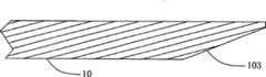
较佳的是,所述盘体的边缘更具有一倾角。Preferably, the edge of the tray further has an inclination.
较佳的是,所述盘体的前端更具有与所述控制单元作电连接的一碰撞感测装置。所述碰撞感测装置为一压力传感器。在另一较佳实施方式中,所述碰撞感测装置更包括有:一滑座;一弹性体,其是套设于所述滑座上;一滑柱,其是以一端与所述弹性体相底靠,所述滑柱的一端更具有一第一接触片;以及一第二接触片,其是与所述第一接触片相对应。Preferably, the front end of the disc body further has a collision sensing device electrically connected to the control unit. The collision sensing device is a pressure sensor. In another preferred embodiment, the collision sensing device further includes: a sliding seat; an elastic body sleeved on the sliding seat; On the bottom of the body, one end of the sliding column further has a first contact piece; and a second contact piece corresponding to the first contact piece.
较佳的是,所述盘体的下方端更具有与所述控制单元作电连接的至少一障碍感测装置。其中所述障碍感测装置更包括有:一滑座;一弹性体,其是套设于所述滑座上;一滑柱,其是以一端与所述弹性体相底靠,所述滑柱的一端更具有一第一接触片;以及一第二接触片,其是与所述第一接触片相对应。Preferably, the lower end of the tray further has at least one obstacle sensing device electrically connected to the control unit. Wherein the obstacle sensing device further includes: a sliding seat; an elastic body, which is sheathed on the sliding seat; a sliding post, which leans against the elastic body at one end, and One end of the column further has a first contact piece; and a second contact piece corresponding to the first contact piece.
较佳的是,所述盘体的一侧更设置有一侧风产生装置。其中,所述侧风产生装置为一离心风扇或者是一轴流风扇。Preferably, a side wind generating device is further provided on one side of the disc body. Wherein, the crosswind generating device is a centrifugal fan or an axial fan.
附图说明Description of drawings
图1为本发明的自走式清洁装置较佳实施例示意图;Fig. 1 is the preferred embodiment schematic diagram of self-propelled cleaning device of the present invention;
图2A至2C为本发明的驱动轮模块较佳实施例示意图;2A to 2C are schematic diagrams of a preferred embodiment of the drive wheel module of the present invention;
图2D为本发明的盘体倾角示意图;Fig. 2D is a schematic diagram of the inclination angle of the disk body of the present invention;
图3为本发明的集尘盒模块较佳实施例示意图;Fig. 3 is a schematic diagram of a preferred embodiment of the dust box module of the present invention;
图4为本发明的离心风扇分解示意图;Fig. 4 is an exploded schematic view of the centrifugal fan of the present invention;
图5A为本发明的离心风扇俯视示意图;5A is a schematic top view of the centrifugal fan of the present invention;
图5B为本发明的离心风扇轴向剖面示意图;Fig. 5B is a schematic axial sectional view of the centrifugal fan of the present invention;
图6A为本发明的集尘盒体立体示意图;Fig. 6A is a three-dimensional schematic view of the dust collecting box of the present invention;
图6B为本发明的集尘盒体立体分解示意图;Fig. 6B is a three-dimensional exploded schematic view of the dust collection box of the present invention;
图6C为本发明的吸尘罩立体示意图;Fig. 6C is a three-dimensional schematic view of the dust collection hood of the present invention;
图6D为本发明的滚动扫刷驱动示意图;Fig. 6D is a schematic diagram of driving the rolling brush of the present invention;
图7为本发明的集尘盒模块于盘体上配置示意图;Fig. 7 is a schematic diagram of the configuration of the dust box module of the present invention on the disk body;
图8为本发明的集尘盒模块于盘体上配置的另一较佳实施例示意图;Fig. 8 is a schematic diagram of another preferred embodiment in which the dust box module of the present invention is arranged on the tray;
图9A为本发明的碰撞感测装置较佳实施例示意图;FIG. 9A is a schematic diagram of a preferred embodiment of the collision sensing device of the present invention;
图9B为本发明的碰撞感测装置动作俯视示意图;FIG. 9B is a schematic top view of the action of the collision sensing device of the present invention;
图10A为本发明的障碍感测装置较佳实施例侧视示意图;FIG. 10A is a schematic side view of a preferred embodiment of the obstacle sensing device of the present invention;
图10B为本发明的障碍感测装置动作侧视示意图。FIG. 10B is a schematic side view of the operation of the obstacle sensing device of the present invention.
附图标记说明:1-自走式清洁装置;10-盘体;101-固定座;102-固定座;Explanation of reference signs: 1-self-propelled cleaning device; 10-disc body; 101-fixed seat; 102-fixed seat;
103-倾角;11-控制单元;12-驱动轮模块;120-驱动体;121-连杆;122-弹性体;123-轮体;124-驱动轴;125-转接件;13-集尘盒模块;130-离心风扇;1300-上壳体;1301-进气口;1302-叶轮;1303-连轴器;1304-转接板;1305-下壳体;1306-出气口;1307-驱动装置;1308-气体流道;1309-螺旋流道;1309a、1309b-流道截面;131-集尘盒体;1310-罩体;1311-盒体;1312-吸尘罩;1313-通孔;1314-进气孔;1315-集尘空间;1316-出气孔;1317-进气口;1318-凹槽;14-碰撞感测装置;140-固定端;141-弹性体;142-滑座;143-滑柱;144-第一接触片;145-第二接触片;146-柱体;147-接触体;15-滚动扫刷;150-扫刷;151-马达减速机;152-第一齿轮;153-第二齿轮;154-齿规皮带;16-障碍感测装置;160-固定端;161-弹性体;162-滑座;163-滑柱;164-第一接触片;165-第二接触片;166-柱体;167-接触体;17-侧风产生装置;3-墙壁;4-侧向障碍物;5-地板;90-吹气方向。103-inclination; 11-control unit; 12-drive wheel module; 120-drive body; 121-connecting rod; 122-elastic body; 123-wheel body; 124-drive shaft; Box module; 130-centrifugal fan; 1300-upper housing; 1301-air inlet; 1302-impeller; 1303-coupling; 1304-adapter plate; 1305-lower housing; 1306-air outlet; Device; 1308-gas channel; 1309-spiral channel; 1309a, 1309b-flow channel section; 131-dust box; 1310-cover; 1311-box; 1312-dust cover; 1313-through hole; 1314-intake hole; 1315-dust collection space; 1316-air outlet; 1317-air inlet; 1318-groove; 14-collision sensing device; 140-fixed end; 141-elastic body; 143-sliding column; 144-first contact piece; 145-second contact piece; 146-pillar; 147-contact body; 15-rolling brush; 150-sweeping brush; 151-motor reducer; 152-first Gear; 153-second gear; 154-gauge belt; 16-obstacle sensing device; 160-fixed end; 161-elastic body; 162-sliding seat; 166-pillar; 167-contact body; 17-side wind generating device; 3-wall; 4-lateral obstacle; 5-floor; 90-blowing direction.
具体实施方式Detailed ways
为了能对本发明的特征、目的及功能有更进一步的认知与了解,下文特将本发明的系统的相关细部结构以及设计的理念原由进行说明,以使得可以了解本发明的特点,详细说明陈述如下:In order to have a further cognition and understanding of the features, purposes and functions of the present invention, the relevant detailed structure and design concept of the system of the present invention will be described below, so that the characteristics of the present invention can be understood and stated in detail as follows:
请参阅图1所示,所述图为本发明的自走式清洁装置较佳实施例示意图。所述自走式清洁装置1包括有一控制单元11、一对驱动轮模块12、一集尘盒模块13以及一对碰撞感测装置14。所述驱动轮组12是设置于一盘体10上而与所述控制单元11作电连接,以提供所述自走式清洁装置移动的动力。所述驱动轮模块12可以接收所述控制单元11传递的信号产生运动,使得所述自走式清洁装置1得以自动的进行清洁吸尘的动作。Please refer to FIG. 1 , which is a schematic diagram of a preferred embodiment of the self-propelled cleaning device of the present invention. The self-propelled
请参阅图2A以及图2B所示,所述图为本发明的驱动轮模块较佳实施例示意图。所述驱动轮模块12包括有一驱动体120、一轮体123、一连杆121以及一弹性体122。所述轮体123,其是通过一转接件125与所述驱动体120的转轴124相连接,以接收所述驱动体120的动力进行转动。通过所述转接件125,使得轮体123与驱动体120得以被拆开,增加使用者维修的便利性。所述连杆121,其是以一端与所述驱动体120相连接,而另一端连接于所述盘体10的一固定座101上。所述弹性体122,其是以一端与所述驱动体120相连接,而另一端连接于所述盘体10的另一固定座102上。在本实施例中,所述驱动体120为一马达与减速齿轮箱的组合。Please refer to FIG. 2A and FIG. 2B , which are schematic diagrams of a preferred embodiment of the driving wheel module of the present invention. The
当轮体123悬空的时候,由于清洁装置的重量配置,驱动体120会与盘体10接触,如图2B所示。反之,如图2C所示当轮体123与地板5接触的时候,将会使得驱动体120与盘体10无法接触而产生分隔的距离,此一距离即为可跨越障碍的高度。当地面有障碍物的时候,盘体10将会被抬起而驱动体120与盘体10之间距将会缩小。如图2D所示,盘体10的设计可于其边缘设计倾角103与以利跨越障碍。When the
请参阅图3所示,所述图为本发明的集尘盒模块较佳实施例示意图。所述集尘盒模块13包括有一离心风扇130与一集尘盒131。请参阅图4所示,所述图为本发明的离心风扇分解示意图。所述离心风扇130包括有一壳体、一叶轮1302以及一驱动装置1307。所述壳体是由一上壳体1300与一下壳体1305所构成。有别于传统的螺旋渐开线所形成的壳体,所述上壳体1300与下壳体1305组成的一容置空间的轴方向截面形状为圆形而非现有技术的截面形状。所述上壳体1300的中心位置上方具有一进气口1301,所述下壳体1305的一侧边上具有一出气口1306。所述叶轮1302其是设置于所述容置空间内。所述驱动装置1307是通过一定位销1303与一转接板1304与所述叶轮1302相连接,以提供转动动力给所述叶轮1302。Please refer to FIG. 3 , which is a schematic diagram of a preferred embodiment of the dust box module of the present invention. The
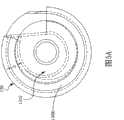
接下来说明所述叶轮于所述壳体内的配置位置。请参阅图5A所示,所述图为本发明的离心风扇俯视示意图。从图中可以了解,由于所述壳体内的容置空间其轴向截面为圆形,因此所述叶轮1302的边缘与所述壳体侧壁间形成具有相等流道宽度D的一气体流道1308。请参阅图5B所示,所述图为本发明的离心风扇轴向剖面示意图。所述叶轮1302本体的轴向中心截面线8上方与所述壳体内壁形成一第一空间A1,而所述叶轮的轴向中心截面线8下方与所述壳体内壁形成一第二空间A2。有别于现有技术,本发明的特征在于所述第二空间A2与所述第一空间A1不对称。如图3以及图5B所示,在所述下壳体1305于所述第二空间A2上具有一螺旋流道1309。所述螺旋流道1309的截面积由所述螺旋流道1309的入口到所述出气口而逐渐增加。以图5B中的1309a表示所述螺旋流道1309的一截面,而1309b表示所述螺旋流道1309的另一截面,从图中可知1309a的面积大于1309b的面积。Next, the arrangement position of the impeller in the casing will be described. Please refer to FIG. 5A , which is a schematic top view of the centrifugal fan of the present invention. It can be understood from the figure that since the housing space in the housing has a circular axial cross-section, a gas channel with equal channel width D is formed between the edge of the
请参阅图6A以及图6B所示,其中,图6A为本发明的集尘盒体立体示意图;图6B为本发明的集尘盒体立体分解示意图。所述集尘盒体131更包括一罩体1310、一吸尘罩1312以及一盒体1311。所述罩体1310具有一凹槽1318,所述罩体1310的一侧上开设有与所述凹槽1318连通的一進氣孔1314,所述罩体1310更具有与所述凹槽1318相连通的一通孔1313,所述通孔1313是与所述离心风扇的进气口1301相连通。所述通孔1313与所述离心风扇的进气口1301间更可设置抽取式的一过滤网,可避免灰尘被吸入离心风扇中。Please refer to FIG. 6A and FIG. 6B , wherein FIG. 6A is a three-dimensional schematic view of the dust collection box of the present invention; FIG. 6B is a three-dimensional exploded schematic view of the dust collection box of the present invention. The
所述盒体1311是设置于所述凹槽1318内,所述盒体1311具有与所述通孔1313以及所述進氯孔1314相连通的一集尘空间1315。所述集尘空间1315可放式一集尘袋(图中未示)且可类似抽屉式的方式容置于所述凹槽1318内,如要更换集尘袋,则可以将所述盒体1311抽出,然后更换集尘袋即可。请参阅图6C所示,所述图为本发明的吸尘罩较佳实施例示意图。所述吸尘罩1313具有一进气口1317以及一出气口1316,所述出气口1316是与所述罩体1310的進氯孔1314相连通。所述吸尘罩1312的进气口1317端更可以设置一滚动扫刷15。如图6D所示,所述滚动扫刷15包括有一位于进气流道入口的扫刷150,以及驱动所述扫刷150转动的一马达减速机151,所述马达减速机151是由马达与齿轮箱所构成。马达减速机151的一端具有一第一齿轮152,在所述扫刷150的一端具有一第二齿轮153。所述第一齿轮152与第二齿轮153是透过一齿规皮带154来带动。所述马达减速机151与驱动轮模块的驱动体所用的组件相同,但是可以采用扭力较小的马达-齿轮箱组合。The
再回到图6A与6B所示,在本实施例中为了要使气体的流道平顺,在清洁装置盘体下方的进气口与集尘盒透过所述吸尘罩1312相连接,且集尘盒罩体1310的进气孔1314开口部位为在所述集尘盒罩体1310的侧边,而非底面,如此便可以不用顾虑集尘的效能而要刻意的去扭曲气体流道而造成气流噪音。也因为如此集尘盒罩体1310及盒体1311的结构设计成抽屉抽取的方式,不但可以降低噪音,更可方便灰尘的清理以及滤网的更换。Returning to Figures 6A and 6B, in this embodiment, in order to make the gas flow path smooth, the air inlet below the cleaning device tray is connected to the dust collection box through the
请参阅图7所示,所述图为本发明的集尘盒模块于盘体上配置示意图。为了加强本发明的自走式清洁装置的清洁能力,所述离心风扇其出气口1306经由一螺旋流道1309导向自走式清洁装置1的侧边,使其可以向下向前吹向死角。在图中,墙壁3与所述自走式清洁装置1间的墙角,可透过本发明的配置,使由出气口1306排出的气流流向90吹向墙角,而扬起灰尘,使得所述自走式清洁装置1可以将灰尘吸入,达到清除墙角的功能。Please refer to FIG. 7 , which is a schematic diagram of the arrangement of the dust box module on the tray of the present invention. In order to enhance the cleaning ability of the self-propelled cleaning device of the present invention, the
请参阅图8所示,所述图为本发明的集尘盒模块于盘体上配置的另一较佳实施例示意图。除了图7的实施例外,本发明更提供一种配置方式,亦即在盘体10上再增设一侧风产生装置17,以提供侧向气流。在图中,墙壁3与所述自走式清洁装置1间的墙角,可透过本发明的实施方式,使由所述侧风产生装置所产生的气流流向90吹向墙角,而扬起灰尘,使得所述自走式清洁装置1可以将灰尘吸入,达到清除墙角的功能。所述侧风产生装置可选择为离心风扇,或者是轴流风扇但不在此限。亦即,只要可以产生侧风以达到扬起死角灰尘的目的的气流产生装置即可。Please refer to FIG. 8 , which is a schematic diagram of another preferred embodiment of the arrangement of the dust box module on the tray of the present invention. In addition to the embodiment shown in FIG. 7 , the present invention further provides a configuration method, that is, a side wind generating device 17 is added on the
再回到图1所示,本发明的防止碰撞的设计,是设置于所述自走式清洁装置的边缘,碰撞感测装置可选择压力传感器。在另一较佳实施例中,所述碰撞感测装置的机构如图9A所示。所述碰撞感测装置14包括有一滑座142、一滑柱143、一第一接触片144、一第二接触片145以及一接触体147。所述滑座142是固定于一固定端140上。所述固定端140是设置于所述盘体10上。所述滑柱143是设置于所述滑座142内可于所述滑座142内进行滑动。所述滑柱143的一端连接有所述第一接触片144。所述第一接触片144与所述固定端140之间具有一弹性体141。所述第二接触片145是设置于所述盘体10上而与所述第一接触片144相对应,所述第一接触片144与所述第二接触片145是与所述控制单元11作电连接。所述第一接触片144的一面上设置有一柱体146通过所述盘体10,在所述柱体146的一端设置有所述接触体147。利用前述的设计使得所述自走式清洁装置在行进过程中可以感测到妨碍清洁的障碍物。Referring back to Fig. 1, the anti-collision design of the present invention is arranged on the edge of the self-propelled cleaning device, and the collision sensing device can be a pressure sensor. In another preferred embodiment, the mechanism of the collision sensing device is shown in Fig. 9A. The
接下来说明所述碰撞感测装置14的动作。在无障碍物的环境下,由于所述弹性体141的弹力,使得所述第一接触片144与所述第二接触片145相接触。如图9B所示,所述图为本发明的碰撞感测装置动作俯视示意图。当一侧向障碍物4出现于所述自走式清洁装置的一侧边时,所述碰撞感测装置14会与所述障碍物4相接触,进而通过所述接触体147而推动所述第一接触片144离开所述第二接触片145。而压缩所述弹性体141。当所述第二接触片145与所述第一接触片144脱离时,所述控制单11元可以感测到电性改变,而辨识出障碍物4的存在,进而控制所述驱动轮模块转向。所述碰撞感测装置的设置数量与位置可视需要而定。Next, the operation of the
此外,本发明于盘体下面也可以设置有多个障碍感测装置16,来判断地面是否平坦或者是有断差的存在。请参阅图10A所示,为本发明的障碍感测装置较佳实施例侧视示意图。所述障碍感测装置16包括有一滑座162、一滑柱163、一第一接触片164、一第二接触片165以及一接触体167。所述滑座162是固定于一固定端160上。所述固定端160是设置于所述盘体10上。所述滑柱163是设置于所述滑座162内可于所述滑座162内进行滑动。所述滑柱163的一端连接有所述第一接触片164。所述第一接触片164与所述固定端160之间具有一弹性体161。所述第二接触片165是设置于所述盘体10上而与所述第一接触片164相对应,所述第一接触片164与所述第二接触片165是与所述控制单元11作电连接。所述第一接触片164的一面上设置有一柱体166通过所述盘体10,在所述柱体166的一端设置有所述接触体167,朝向地面,而与地面相接触。所述接触体167可以随着自走式清洁装置的移动而滚动。In addition, in the present invention, a plurality of
接下来说明所述障碍感测装置的动作。如图10A所示,在正常运作下,所述障碍感测装置16会与地面相接触,而压缩所述弹性体161,进而使所述第一接触片164离开所述第二接触片165。如图10B所示,所述图为本发明的障碍感测装置动作侧视示意图。当遇到有断差或者是落差时,由于无外力作用,因此所述弹性体161的弹力会推动所述第一接触片164使得所述第一接触片164与所述第二接触片165接触,进而使所述控制单元11可以感测到电性改变,而辨识出落差的存在,进而控制所述驱动轮模块转向。所述障碍感测装置的设置数量与位置可视需要而定。Next, the operation of the obstacle sensing device will be described. As shown in FIG. 10A , under normal operation, the
唯以上所述,仅为本发明的较佳实施例,当不能以之限制本发明范围。即大凡依本发明权利要求所做的均等变化及修饰,仍将不失本发明的要义所在,故都应视为本发明的进一步实施状况。The above descriptions are only preferred embodiments of the present invention, and should not be used to limit the scope of the present invention. That is, all equivalent changes and modifications made according to the claims of the present invention will still not lose the gist of the present invention, so all should be regarded as further implementation status of the present invention.
综合上述,本发明提供的自走式清洁装置,具有吸尘效率高、低噪音以及方便清理的优点。In summary, the self-propelled cleaning device provided by the present invention has the advantages of high dust collection efficiency, low noise and convenient cleaning.
Claims (13)
Translated fromChinesePriority Applications (1)
| Application Number | Priority Date | Filing Date | Title |
|---|---|---|---|
| CN200610152672XACN101152062B (en) | 2006-09-25 | 2006-09-25 | self-propelled cleaning device |
Applications Claiming Priority (1)
| Application Number | Priority Date | Filing Date | Title |
|---|---|---|---|
| CN200610152672XACN101152062B (en) | 2006-09-25 | 2006-09-25 | self-propelled cleaning device |
Publications (2)
| Publication Number | Publication Date |
|---|---|
| CN101152062A CN101152062A (en) | 2008-04-02 |
| CN101152062Btrue CN101152062B (en) | 2010-09-29 |
Family
ID=39254109
Family Applications (1)
| Application Number | Title | Priority Date | Filing Date |
|---|---|---|---|
| CN200610152672XAExpired - Fee RelatedCN101152062B (en) | 2006-09-25 | 2006-09-25 | self-propelled cleaning device |
Country Status (1)
| Country | Link |
|---|---|
| CN (1) | CN101152062B (en) |
Families Citing this family (12)
| Publication number | Priority date | Publication date | Assignee | Title |
|---|---|---|---|---|
| CN102218740B (en)* | 2010-04-14 | 2014-03-26 | 泰怡凯电器(苏州)有限公司 | Self-moving device |
| US9596971B2 (en)* | 2011-10-21 | 2017-03-21 | Samsung Electronics Co., Ltd. | Robot cleaner and control method for the same |
| CN103356122A (en)* | 2012-04-05 | 2013-10-23 | 科沃斯机器人科技(苏州)有限公司 | Glass cleaning device |
| JP6068824B2 (en)* | 2012-05-01 | 2017-01-25 | シャープ株式会社 | Self-propelled electronic device |
| JP6178677B2 (en)* | 2013-09-09 | 2017-08-09 | シャープ株式会社 | Self-propelled electronic device |
| CN103767624B (en)* | 2014-03-03 | 2016-06-29 | 柯约瑟 | The self-propelled dust exhaust apparatus being convenient to clean |
| CN104757911B (en)* | 2014-11-26 | 2018-02-06 | 深圳市银星智能科技股份有限公司 | The cleaning method and Intelligent robot for sweeping floor of Intelligent robot for sweeping floor |
| CN105982621B (en)* | 2016-04-14 | 2019-12-13 | 北京小米移动软件有限公司 | Air duct structure of automatic cleaning equipment and automatic cleaning equipment |
| CN107397510A (en)* | 2017-08-22 | 2017-11-28 | 安徽风向标清洁设备有限公司 | Sweeper |
| CN109419453A (en)* | 2017-09-01 | 2019-03-05 | 广东宝乐机器人股份有限公司 | Mobile mechanism and mobile robot with the mobile mechanism |
| CN107972141A (en)* | 2017-12-28 | 2018-05-01 | 苏州时开纽数控装备有限公司 | Timber tongue-and-groove processing machine dust absorbing structure |
| CN109770795B (en)* | 2019-03-31 | 2020-12-08 | 山东沃华远达环境科技股份有限公司 | Sweeper capable of achieving targeted sweeping based on repeated walking |
Citations (3)
| Publication number | Priority date | Publication date | Assignee | Title |
|---|---|---|---|---|
| CN1493247A (en)* | 2002-10-31 | 2004-05-05 | ������������ʽ���� | Robot vacuum cleaner system and method for docking with charging equipment |
| CN1600220A (en)* | 2003-09-27 | 2005-03-30 | 乐金电子(天津)电器有限公司 | Wheel set of automatic controllable cleaner |
| CN1734102A (en)* | 2004-08-13 | 2006-02-15 | Lg电子株式会社 | Centrifugal fan and vacuum cleaner having the centrifugal fan |
- 2006
- 2006-09-25CNCN200610152672XApatent/CN101152062B/ennot_activeExpired - Fee Related
Patent Citations (3)
| Publication number | Priority date | Publication date | Assignee | Title |
|---|---|---|---|---|
| CN1493247A (en)* | 2002-10-31 | 2004-05-05 | ������������ʽ���� | Robot vacuum cleaner system and method for docking with charging equipment |
| CN1600220A (en)* | 2003-09-27 | 2005-03-30 | 乐金电子(天津)电器有限公司 | Wheel set of automatic controllable cleaner |
| CN1734102A (en)* | 2004-08-13 | 2006-02-15 | Lg电子株式会社 | Centrifugal fan and vacuum cleaner having the centrifugal fan |
Also Published As
| Publication number | Publication date |
|---|---|
| CN101152062A (en) | 2008-04-02 |
Similar Documents
| Publication | Publication Date | Title |
|---|---|---|
| CN101152062B (en) | self-propelled cleaning device | |
| TWI312279B (en) | Robotic vacuum cleaner | |
| CN101273860B (en) | Robot cleaner with improved dust collector | |
| US7827653B1 (en) | Cleaning device with sweeping and vacuuming functions | |
| TWI308197B (en) | Apparatus of centrifugal fan and a dust-collecting module of using the same | |
| US7412750B2 (en) | Floorcloth attached suction brush for vacuum cleaner | |
| CN107041714B (en) | Robot cleaner | |
| CN106793904B (en) | Robot cleaner | |
| CN1985747A (en) | Compact automatic vacuum cleaner | |
| TW201500026A (en) | Dust collecting method and apparatus of self-propelled cleaning equipment | |
| KR102195707B1 (en) | Cleaner | |
| JP2005013709A (en) | Upright vacuum cleaner | |
| JP2009189795A (en) | Vacuum cleaner | |
| CN103190862A (en) | Pneumatic floor brush and vacuum cleaner thereof | |
| KR20090034493A (en) | robotic vacuum | |
| CN1306899C (en) | Cleaner having brush | |
| JP2003204903A (en) | Electric vacuum cleaner | |
| CN101153615A (en) | Centrifugal fan and dust collecting box module with same | |
| CN101797134B (en) | Dust collection device | |
| CN101732001A (en) | Dust collecting barrel of suction cleaner | |
| US20120210685A1 (en) | Apparatus of centrifugal fan and a dust-collecting module using the same | |
| KR102171271B1 (en) | Cleaner | |
| CN101822504A (en) | Fan drive compression board component of dust collecting barrel | |
| CN218552213U (en) | A ground brush mechanism and cleaning device | |
| KR20070099275A (en) | Robot cleaner with air cleaning function |
Legal Events
| Date | Code | Title | Description |
|---|---|---|---|
| C06 | Publication | ||
| PB01 | Publication | ||
| C10 | Entry into substantive examination | ||
| SE01 | Entry into force of request for substantive examination | ||
| C14 | Grant of patent or utility model | ||
| GR01 | Patent grant | ||
| CF01 | Termination of patent right due to non-payment of annual fee | ||
| CF01 | Termination of patent right due to non-payment of annual fee | Granted publication date:20100929 |