CN101151639B - Image processing device and image processing method - Google Patents
Image processing device and image processing methodDownload PDFInfo
- Publication number
- CN101151639B CN101151639BCN2006800108630ACN200680010863ACN101151639BCN 101151639 BCN101151639 BCN 101151639BCN 2006800108630 ACN2006800108630 ACN 2006800108630ACN 200680010863 ACN200680010863 ACN 200680010863ACN 101151639 BCN101151639 BCN 101151639B
- Authority
- CN
- China
- Prior art keywords
- image
- fading
- photo
- image processing
- correction
- Prior art date
- Legal status (The legal status is an assumption and is not a legal conclusion. Google has not performed a legal analysis and makes no representation as to the accuracy of the status listed.)
- Active
Links
Images


Classifications
- G—PHYSICS
- G06—COMPUTING OR CALCULATING; COUNTING
- G06T—IMAGE DATA PROCESSING OR GENERATION, IN GENERAL
- G06T7/00—Image analysis
- G06T7/10—Segmentation; Edge detection
- G06T7/12—Edge-based segmentation
- H—ELECTRICITY
- H04—ELECTRIC COMMUNICATION TECHNIQUE
- H04N—PICTORIAL COMMUNICATION, e.g. TELEVISION
- H04N1/00—Scanning, transmission or reproduction of documents or the like, e.g. facsimile transmission; Details thereof
- H04N1/40—Picture signal circuits
- H04N1/409—Edge or detail enhancement; Noise or error suppression
- H04N1/4092—Edge or detail enhancement
- H—ELECTRICITY
- H04—ELECTRIC COMMUNICATION TECHNIQUE
- H04N—PICTORIAL COMMUNICATION, e.g. TELEVISION
- H04N1/00—Scanning, transmission or reproduction of documents or the like, e.g. facsimile transmission; Details thereof
- H04N1/46—Colour picture communication systems
- H04N1/56—Processing of colour picture signals
- H04N1/58—Edge or detail enhancement; Noise or error suppression, e.g. colour misregistration correction
- G—PHYSICS
- G06—COMPUTING OR CALCULATING; COUNTING
- G06T—IMAGE DATA PROCESSING OR GENERATION, IN GENERAL
- G06T2207/00—Indexing scheme for image analysis or image enhancement
- G06T2207/10—Image acquisition modality
- G06T2207/10016—Video; Image sequence
- G—PHYSICS
- G06—COMPUTING OR CALCULATING; COUNTING
- G06T—IMAGE DATA PROCESSING OR GENERATION, IN GENERAL
- G06T2207/00—Indexing scheme for image analysis or image enhancement
- G06T2207/20—Special algorithmic details
- G06T2207/20048—Transform domain processing
- G—PHYSICS
- G06—COMPUTING OR CALCULATING; COUNTING
- G06T—IMAGE DATA PROCESSING OR GENERATION, IN GENERAL
- G06T2207/00—Indexing scheme for image analysis or image enhancement
- G06T2207/20—Special algorithmic details
- G06T2207/20048—Transform domain processing
- G06T2207/20061—Hough transform
- G—PHYSICS
- G06—COMPUTING OR CALCULATING; COUNTING
- G06T—IMAGE DATA PROCESSING OR GENERATION, IN GENERAL
- G06T2207/00—Indexing scheme for image analysis or image enhancement
- G06T2207/20—Special algorithmic details
- G06T2207/20092—Interactive image processing based on input by user
Landscapes
- Engineering & Computer Science (AREA)
- Multimedia (AREA)
- Signal Processing (AREA)
- Computer Vision & Pattern Recognition (AREA)
- Physics & Mathematics (AREA)
- General Physics & Mathematics (AREA)
- Theoretical Computer Science (AREA)
- Image Processing (AREA)
- Facsimile Image Signal Circuits (AREA)
- Color Image Communication Systems (AREA)
- Image Analysis (AREA)
- Studio Devices (AREA)
Abstract
Description
Translated fromChinese技术领域technical field
本发明涉及一种图像处理装置和图像处理方法,用于从拍摄的图像中提取预定区域(相片(photographic print)等)。 The present invention relates to an image processing device and image processing method for extracting a predetermined area (photographic print, etc.) from a photographed image. the
背景技术Background technique
近年来,数字照相机作为照相设备已经普及,并且照片的数字化不断发展。 In recent years, digital cameras have been popularized as photographic devices, and digitization of photographs has been progressing. the
照片的数字化具有多种优点。例如,照片可以被压缩存储,易于复制照片,以及可以以多种方式浏览照片,例如连续地或以随机顺序。从这些优点的角度来看,通过使用银盐胶片获得的传统照片的数字化将被广泛使用。因为数字照相机近来才被普及,所以许多人有这种传统照片。传统照片包括在印刷纸和显影胶片上的照片。下文中,它们被通称为“相片”。 Digitization of photographs has several advantages. For example, photos can be stored compressed, photos can be easily copied, and photos can be browsed in a variety of ways, such as sequentially or in random order. From the standpoint of these advantages, digitization of conventional photographs obtained by using silver halide film will be widely used. Because digital cameras have only recently become popular, many people have this traditional photo. Traditional photographs include photographs on printed paper and developed film. Hereinafter, they are collectively referred to as "photographs". the
例如可以通过使用平面扫描器扫描相片来使相片数字化。如公知的,相片的原始色彩随着时间的流逝由于化学变化而变色(褪色)。出于这个原因,一些扫描器安装有图像处理设备,其执行用于校正变色的褪色校正。 A photo can be digitized, for example, by scanning the photo with a flatbed scanner. As is well known, the original colors of a photograph become discolored (fade) over time due to chemical changes. For this reason, some scanners are equipped with an image processing device that performs fading correction for correcting discoloration. the
进行褪色校正的传统图像处理设备的实例在公开号为No.2002-101313的日本专利申请中进行了描述。这份专利文件描述的传统图像处理设备检测所获取的图像的褪色程度,并根据检测结果执行褪色校正。程度检测使得有可能通过仅仅获取图像来进行适当的褪色校正。 An example of a conventional image processing apparatus that performs fading correction is described in Japanese Patent Application Laid-Open No. 2002-101313. The conventional image processing apparatus described in this patent document detects the degree of fading of an acquired image, and performs fading correction based on the detection result. Level detection makes it possible to perform appropriate fading corrections by just acquiring an image. the
必须只对是褪色校正对象的图像应用程度检测。否则,不可能准确识别图像上出现了怎样的褪色。如公知的,平面扫描器被用来扫描直接放在扫描台上或被置于馈送器上的扫描对象。因此,有可能容易地只扫描要对其应用褪色校正的相片。 Level detection must be applied only to images that are the subject of fading correction. Otherwise, it is impossible to identify exactly what kind of fading occurs on the image. As is known, planar scanners are used to scan objects to be scanned either directly on the scanning table or placed on a feeder. Therefore, it is possible to easily scan only a photograph to which fading correction is to be applied. the
同时,相片通常贴在照相薄等(这里包括将相片放入至少一面透明的文件中的方法)中。固定到照相薄上的相片不能放置在馈送器上。而且难于将它们适当地放置在扫描台上。通常不可能只扫描固定到照相薄上的目标相片。出于这个原因,当扫描时,通常将固定到照相薄上的相片从照相薄上取下。因此,当扫描器被用来扫描相片时,必需对每张相片进行下述繁重的工作。即,从照相薄取下相片,将其放置在扫描台上,并且扫描完成后,将扫描台上的相片重新固定到照相薄。 Meanwhile, the photos are usually pasted in a photo book or the like (including a method of putting the photos in a document with at least one side transparent). Photos pinned to photobooks cannot be placed on the feeder. And it is difficult to place them properly on the scanning table. It is generally not possible to scan only target photos pinned to a photobook. For this reason, when scanning, the photos fixed to the photobook are usually removed from the photobook. Therefore, when the scanner is used to scan photographs, it is necessary to perform the following heavy work for each photograph. That is, the photo is removed from the photobook, placed on the scanning table, and after scanning is complete, the photo on the scanning table is re-fixed to the photobook. the
在从照相薄取下时,相片可能会损坏。例如,当相片粘在照相薄中覆盖相片的透明页上时,极有可能损坏它们。因此,希望能够在不需要将相片从照相薄取出的情况下扫描相片。 Photos may be damaged when removed from the photo album. For example, when photos are glued to the transparent pages covering the photos in a photobook, there is a high risk of damaging them. Therefore, it would be desirable to be able to scan photos without having to remove the photos from the photo album. the
使用在公开号为No.2002-354331的日本专利申请中描述的发明,有可能在不需要将相片从照相薄取出的情况下扫描相片。然而,对用户来说更方便和优选的是能够使用便携的照相设备,如数字照相机。利用便携的照相设备可能以任意的位置关系拍摄对象。另一方面,可以以任意的位置关系拍摄对象的优点意味着,难以知道实际上相片是在什么拍摄条件(照相设备和对象的位置关系等)下拍摄的。这使得难以识别一张具体的相片。 Using the invention described in Japanese Patent Application Laid-Open No. 2002-354331, it is possible to scan photos without taking them out of a photo album. However, it is more convenient and preferable for the user to be able to use a portable photographic device, such as a digital camera. Objects can be photographed in any positional relationship with a portable camera. On the other hand, the advantage that subjects can be photographed in any positional relationship means that it is difficult to know under what conditions the photograph was actually taken (positional relation of camera and subject, etc.). This makes it difficult to identify a specific photo. the
发明内容Contents of the invention
本发明的目的是提供一种图像处理装置和图像处理方法,其从拍摄图像中提取被认为发生了褪色的预定图像区域。 An object of the present invention is to provide an image processing device and an image processing method that extract a predetermined image area that is considered to have faded from a captured image. the
根据本发明的一个实施例,一种图像处理装置,包括: According to one embodiment of the present invention, an image processing device includes:
图像获取单元,其获取包括照片的对象的图像; an image acquisition unit that acquires an image of an object including a photograph;
边缘检测单元,其在由所述图像获取单元获取的对象的图像中检测所述照片的边缘; an edge detection unit that detects the edge of the photo in the image of the object acquired by the image acquisition unit;
褪色检测器,其检测一内部部分的褪色,该内部部分通过除去由所述照片的所检测的边缘包围的图像区域的空白边来限定;以及 a fade detector that detects fade of an interior portion defined by removing the margins of the image area surrounded by the detected edges of the photo; and
图像处理单元,其基于由所述褪色检测器检测出的褪色对所述内部部分执行褪色校正,其中所述空白边中没有图像;并且所述区域为没有失真和旋转的矩形形状。 an image processing unit that performs fading correction on the inner portion based on the fading detected by the fading detector, wherein there is no image in the margin; and the area has a rectangular shape without distortion and rotation. the
根据本发明的另一实施例,一种图像处理方法,包括: According to another embodiment of the present invention, an image processing method includes:
获取步骤,用于获取包括照片的对象的图像; an acquisition step for acquiring an image of an object including a photograph;
检测步骤,用于在所获取的对象的图像中检测所述照片的边缘; a detection step for detecting edges of said photo in the acquired image of the object;
褪色检测步骤,用于检测一内部部分的褪色,该内部部分通过除去由所述照片的所检测的边缘包围的图像区域的空白边来限定;以及 a fade detection step for detecting fade of an interior portion defined by removing the margins of the image area surrounded by the detected edges of said photo; and
褪色校正执行步骤,用于基于检测出的褪色,对所述内部部分执行褪色校正,其中所述空白边中没有图像;并且所述区域为没有失真和旋转的矩形形状。 a color fading correction performing step of performing color fading correction on the inner portion, wherein the margin has no image; and the area is in a rectangular shape without distortion and rotation, based on the detected color fading. the
图1是说明根据第一实施例的包括图像处理装置的照相设备的图; FIG. 1 is a diagram illustrating a photographic apparatus including an image processing device according to a first embodiment;
图2是说明根据第一实施例的包括图像处理装置的照相设备的结构图; 2 is a block diagram illustrating a photographic apparatus including an image processing device according to a first embodiment;
附图说明Description of drawings
图3A、3B、3C、3D、3E、3F和3G是说明边缘检测方法的图; 3A, 3B, 3C, 3D, 3E, 3F and 3G are diagrams illustrating edge detection methods;
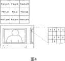
图4是说明用标记法分配标记的图; Figure 4 is a diagram illustrating the assignment of marks by the notation method;
图5A、5B、5C、5D、5E和5F是说明当对象被拍摄时,显示在液晶显示单元上的各种图像的图; 5A, 5B, 5C, 5D, 5E and 5F are diagrams illustrating various images displayed on a liquid crystal display unit when an object is photographed;
图6A和6B是说明霍夫(Hough)变换的图; 6A and 6B are diagrams illustrating Hough transform;
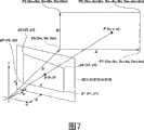
图7是说明相片和相片的投影图像之间的关系的图; 7 is a diagram illustrating the relationship between a photo and a projected image of the photo;
图8A和8B是说明由于褪色而造成的失真的图; 8A and 8B are graphs illustrating distortion due to fading;
图9是照相机基本处理的流程图; Fig. 9 is a flow chart of camera basic processing;
图10是边缘检测处理的流程图; Fig. 10 is the flowchart of edge detection processing;
图11是通过进行标记的外围边缘擦除处理的流程图; Fig. 11 is a flowchart of the peripheral edge erasing process by performing marking;
图12是褪色程度检测处理的流程图; Fig. 12 is the flowchart of fading degree detection process;
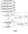
图13是褪色校正引导显示处理的流程图; Fig. 13 is a flowchart of fading correction guide display processing;
图14是褪色校正处理的流程图; Figure 14 is a flowchart of fading correction processing;
图15是褪色校正引导显示处理的修改的流程图;以及 Figure 15 is a flowchart of a modification of the fading correction guide display process; and
图16是根据第二实施例的通过进行标记的外围边缘擦除处理的 流程图。 Fig. 16 is a flowchart of peripheral edge erasing processing by marking according to the second embodiment. the
具体实施方式Detailed ways
下文将参考附图详细描述本发明的实施例。 Hereinafter, embodiments of the present invention will be described in detail with reference to the accompanying drawings. the
<第一实施例> <First embodiment>
图1是说明根据第一实施例的包括图像处理装置的照相设备的图。照相设备1被假定为便携式设备,如数字照相机或具有照相功能的蜂窝电话。如上所述,对象2是用于存储相片3的照相薄,其中相片是显影胶片或印图纸上的照片。下文中参考标记2只指作为对象的照相薄。 FIG. 1 is a diagram illustrating a photographing apparatus including an image processing device according to a first embodiment. The
图2是说明照相设备1的结构的图。如图2所示,照相设备1包括:图像数据生成单元21,用于生成图像数据,其是通过对通过拍摄拍摄目标对象而获得的图像进行数字化而获得的;数据处理单元22,用于对所述图像数据执行图像处理;以及用户接口单元23,用于与用户交换信息。 FIG. 2 is a diagram illustrating the structure of the photographing
图像数据生成单元21包括光学透镜设备101和图像传感器102。光学透镜设备101组成一个光学系统,其在图像传感器102上形成对象的图像,并能够调节拍摄的参数设置,如焦点、曝光和白平衡。图像传感器102将由光学透镜设备101聚焦/成像的对象的图像变换为数字化的图像数据。图像传感器102由CCD等组成。 The image
图像数据生成单元21执行高分辨率图像拍摄和低分辨率图像拍摄(预览拍摄)。在低分辨率图像拍摄中,图像分辨率例如是相对低的约XGA(扩展的图形阵列:1024×768点)。然而,有可能以约30fps(帧/秒)的速度进行视频记录或图像读取。另一方面,在高分辨率图像拍摄中,以例如可拍摄的最大像素(点)数进行拍摄。因为以最大像素数进行拍摄,与低分辨率图像拍摄的情况相比,拍摄速度和图像读取速度较低。 The image
数据处理单元22包括:存储器201,其存储从图像传感器102输出的图像数据;视频输出设备202,用于显示存储在存储器201中的图像数据;图像处理单元203,用于对图像数据执行图像处理;CPU 204,其控制整个照相设备1;以及程序代码存储设备(下文中缩写为“代码存储设备”)205,其存储由CPU 204运行的程序(程序代码)。存储设备205例如是ROM或闪速存储器。根据本发明的图像处理装置被实现为图像处理设备203。 The
用户接口单元23包括:液晶显示单元301;操作单元302,其包括各种操作部件;PC接口设备303,用于向外部设备输入数据/从外部设备输出数据,所述外部设备诸如个人计算机(PC);以及外部存储设备304。 The
操作单元302包括例如电源键、模式切换开关、快门键、菜单键、箭头键、调焦键和缩放键作为操作部分,未对它们进行说明。模式切换开关包括用于切换记录(拍摄)/回放模式的开关,以及用于切换正常/褪色校正中的子模式的开关(下文中,为了区分,将后者改写为“子模式切换开关”)。虽然没有示出,但是还提供了子CPU,其检测开关的状态变化,并传送与该变化相对应的检测信号给CPU 204。外部存储设备304例如是便携式存储介质(例如,闪速存储器),其能够附接到装置1或者从装置1分离,或者是硬盘设备。 The
CPU 204通过加载并执行存储在代码存储设备205中的程序来控制整个照相设备1。CPU 204按照从操作单元302输入的命令信号根据需要控制图像数据生成单元21的光学透镜设备101或图像传感器102,从而调节焦点、白平衡等,或者改变曝光时间。 The
当设定了记录模式时,即使在拍摄之前CPU 204也能使图像传感器102输出图像数据。视频输出设备202从存储在存储器201中的图像数据中生成用于显示的RGB信号,并输出该生成的信号给液晶显示单元301。通过这种方式,液晶显示单元301能够显示拍摄对象或拍摄的图像的图像。来自视频输出设备202的RGB信号能够通过终端(未示出)被输出到外部设备,以使得RGB信号可以被电视、PC、投影仪等显示。 When the recording mode is set, the
存储在存储器201中的图像数据以这样的方式保存,即CPU 204以文件格式将图像数据存储在外部存储设备304中。存储在外部存储设备304中的图像数据可以通过PC接口设备303输出。PC接口设 备303例如符合USB。 The image data stored in the
CPU 204根据需要命令图像处理设备203对图像数据执行图像处理。当图像数据保存在外部存储设备304中时,CPU 204使图像处理设备203执行压缩处理。当设置了回放模式时,CPU 204根据操作单元302的操作,向存储器201加载由压缩处理所编码的要保存在外部存储设备304中的图像数据。然后CPU 204使图像处理设备203执行解压缩处理,以将图像数据显示在液晶显示单元301上。 The
如上所述,在记录模式中,正常模式或褪色校正模式可以被设定为子模式。正常模式是照原样加载所拍摄的图像的模式。褪色校正模式是通过自动提取具有对象的图像区域来执行褪色校正的模式,其中假定该对象的原始色彩已经变色(褪色)。准备褪色校正模式,以使得可以在相片3固定到照相薄2等(即,不需要将相片从照相薄2等取下)的状态下适当地执行数字化。当设定了褪色校正模式时,CPU 204使图像处理设备203执行下面的图像处理。图像处理的对象是通过拍摄获得的图像数据。“通过拍摄获得的图像数据”下文中称为“拍摄的图像数据”或“原始图像数据”,以将它们与拍摄前存储在存储器201中的图像数据区分开。由数据表示的图像称为“拍摄的图像”或“原始图像”。 As described above, in the recording mode, the normal mode or the fading correction mode can be set as a sub-mode. The normal mode is a mode in which captured images are loaded as they are. The color fading correction mode is a mode that performs color fading correction by automatically extracting an image area with an object whose original color is assumed to have been discolored (faded). A fading correction mode is prepared so that digitization can be properly performed in a state where the
图像处理主要包括:(1)边缘检测,(2)倾斜拍摄校正,(3)对检测的边缘区域进行褪色程度检测,以及(4)褪色校正。边缘检测处理用来检测在对象2的拍摄图像中包括的相片2(相片图像)的图像边缘(边界线)。由于相片3的状态或相对于照相机的位置关系,相片图像通常或多或少地失真。除非相片表面处于与由光学透镜设备101组成的光学系统的光轴垂直的位置关系(下文中称为“理想位置关系”),否则即使相片3是完全平面的,相片图像也会失真,即,当相片3从倾斜方向拍摄时。倾斜拍摄校正处理用来校正歪曲。 The image processing mainly includes: (1) edge detection, (2) oblique shooting correction, (3) detecting the fading degree of the detected edge area, and (4) fading correction. The edge detection processing is to detect the image edge (border line) of the photograph 2 (photograph image) included in the captured image of the
根据保存的状态,即湿度、温度、紫外线辐射等,在相片3中发生化学变化,并且相片3变色,使得它的原始色彩褪去,这导致了褪色。对检测的边缘区域的褪色程度检测处理用来检测受到倾斜拍摄校正处理的相片图像(检测的边缘区域)上褪色的程度(褪色程度)。褪色 校正处理用来根据由褪色程度检测处理指定的褪色程度来对相片图像执行褪色校正,以使得由褪色改变的色彩接近原始色彩。 Depending on the state of preservation, ie, humidity, temperature, ultraviolet radiation, etc., chemical changes occur in the
下面,将详细描述由图像处理设备203执行的上述各种图像处理。图像处理设备203使用存储有拍摄的图像数据的存储器201作为工作区域来执行各种图像处理。用于执行图像处理的程序存储在包含在图像处理设备203中的非易失性存储器中,或由CPU 204访问的代码存储设备205中。这里,假定是后者。在这种情况下,CPU 204从代码存储设备205加载用于各种图像处理的程序,并且在需要时将这些程序传送到图像处理设备203。 Next, the above-described various image processing performed by the
图3A至3G是说明边缘检测处理中的边缘检测方法的图。 3A to 3G are diagrams illustrating an edge detection method in edge detection processing. the
图3A中示出的预览图像是通过拍摄照相薄2中的相片3的拍摄的图像,它的图像数据存储在存储器201中。图3B中示出的二进制边缘图像是通过对预览图像执行边缘检测而创建的。该创建是通过使用例如用于边缘检测的滤波器而实施的,该滤波器被称为Roberts滤波器。 The preview image shown in FIG. 3A is a captured image by capturing the
在这个Roberts滤波器中,通过对四个相邻的像素执行两种类型的加权来确定两个不同的值Δ1和Δ2,其中所述四个相邻的像素由一个目标像素和三个与其相邻的像素组成,并且对这些不同的值进行平均,以计算目标像素的像素值,以突出边缘。假设目标像素的坐标是(x,y),像素值是f(x,y),则Roberts滤波器进行滤波处理后的像素值g(x,y)(变换后)表示如下。 In this Roberts filter, two different values Δ1 and Δ2 are determined by performing two types of weighting on four adjacent pixels consisting of a target pixel and three The adjacent pixels are composed, and these different values are averaged to calculate the pixel value of the target pixel to highlight the edge. Assuming that the coordinates of the target pixel are (x, y) and the pixel value is f(x, y), then the pixel value g(x, y) (after transformation) after filtering by the Roberts filter is expressed as follows. the
Δ1=1·f(x,y)+0·f(x+1,y)+0·f(x,y-1)-1·f(x+1,y-1) Δ1=1·f(x,y)+0·f(x+1,y)+0·f(x,y-1)-1·f(x+1,y-1)
=f(x,y)-f(x+1,y-1) =f(x, y)-f(x+1, y-1)
Δ2=0·f(x,y)+1·f(x+1,y)=1·f(x,y-1)+0·f(x+1,y-1) …(1) Δ2=0·f(x, y)+1·f(x+1, y)=1·f(x, y-1)+0·f(x+1, y-1) …(1)
根据预定的阈值TH对由公式(1)获得的像素值g(x,y)进行二进制化。阈值TH可以被确定为固定值。然而,它可以根据需要通过诸如可变阈值方法或判别分析方法的方法确定。像素值g(x,y)通过使用阈值TH的下述公式被变换为二进制像素值h(x,y)。如图3B所示, 二进制化的图像(二进制边缘图像)h通过变换被创建(生成),其中该二进制化的图像(二进制边缘图像)h表示在拍摄的图像上提取的边缘。 The pixel value g(x, y) obtained by formula (1) is binarized according to a predetermined threshold TH. The threshold TH can be determined as a fixed value. However, it can be determined by a method such as a variable threshold method or a discriminant analysis method as desired. The pixel value g(x, y) is converted into a binary pixel value h(x, y) by the following formula using the threshold TH. As shown in FIG. 3B , a binarized image (binary edge image) h representing an edge extracted on a captured image is created (generated) by transformation. the

存在这样的可能,即相片3放置的位置(背景)的色彩近似于相片3的外围的色彩。尤其是,例如,其中具有蓝天背景的相片3被固定到蓝色页面的情况。即使在这种情况下,例如,当图像数据的格式是YUV时,通过下面的公式也可能突出相片3和蓝色页面之间的差别。在下面的公式中,不仅亮度值Y的差值,而且每种色彩成分的差值U和V,都分别被确定和平均。然后,平均值与系数n相乘,并且将其加到针对亮度值Y而确定的平均值上。 There is a possibility that the color of the position (background) where the
ΔY1=1·fy(x,y)+0·fy(x+1,y)+0·fy(x,y-1)-1·fy(x+1,y-1) ΔY1=1·fy(x,y)+0·fy(x+1,y)+0·fy(x,y-1)-1·fy(x+1,y-1)
=fy(x,y)-fy(x+1,y-1) =fy(x, y)-fy(x+1, y-1)
ΔY2=0·fy(x,y)+1·fy(x+1,y)-1·fy(x,y-1)+0·fy(x+1,y-1) ΔY2=0·fy(x, y)+1·fy(x+1, y)-1·fy(x, y-1)+0·fy(x+1, y-1)
=fy(x+1,y)-fy(x,y-1) =fy(x+1, y)-fy(x, y-1)
ΔU1=1·fu(x,y)+0·fu(x+1,y)+0·fu(x,y-1)-1·fu(x+1,y-1) ΔU1=1·fu(x,y)+0·fu(x+1,y)+0·fu(x,y-1)-1·fu(x+1,y-1)
=fu(x,y)-fu(x+1,y-1) =fu(x,y)-fu(x+1,y-1)
ΔU2=0·fu(x,y)+1·fu(x+1,y)-1·fu(x,y-1)+0·fu(x+1,y-1) …(3) ΔU2=0·fu(x, y)+1·fu(x+1, y)-1·fu(x, y-1)+0·fu(x+1, y-1) …(3)
=fu(x+1,y)-fu(x,y-1) =fu(x+1, y)-fu(x, y-1)
ΔV1=1·fv(x,y)+0·fv(x+1,y)+0·fv(x,y-1)-1·fv(x+1,y-1) ΔV1=1·fv(x,y)+0·fv(x+1,y)+0·fv(x,y-1)-1·fv(x+1,y-1)
=fv(x,y)-fv(x+1,y-1) =fv(x, y)-fv(x+1, y-1)
ΔV2=0·fy(x,y)+1·fv(x+1,y)-1·fv(x,y-1)+0·fv(x+1,y-1) ΔV2=0·fy(x, y)+1·fv(x+1, y)-1·fv(x, y-1)+0·fv(x+1, y-1)
=fv(x+1,y)-fv(x,y-1) =fv(x+1, y)-fv(x, y-1)
在公式(3)中,有下面所示的三个分量的平方和。为了边缘提取而执行利用Roberts滤波器的变换。因为对于提取边缘是足够的,所以像素值g(x,y)可以通过只使用三个分量的平方和中最大的一个来 计算。 In formula (3), there is the sum of squares of the three components shown below. Transformation with a Roberts filter is performed for edge extraction. Since it is sufficient for extracting edges, the pixel value g(x, y) can be calculated by using only the largest of the sums of squares of the three components. the
即使图像数据是其它格式的,也可以执行上面提及的强调。当图像数据是用RGB表示色彩的格式时,针对每个RGB分量由公式(1)分别确定像素值g(x,y),并且应用其中最大的一个,这使得能够强调。这与图像数据是用CMY或CMYK表示色彩的格式的情况相同。 Even if the image data is in other formats, the above-mentioned emphasizing can be performed. When image data is in a format expressing colors in RGB, pixel values g(x, y) are individually determined by formula (1) for each RGB component, and the largest one is applied, which enables emphasis. This is the same as the case where image data is in a format expressing colors in CMY or CMYK. the
为了拍摄固定到照相薄2的相片3,很难只获取期望的相片3。由数字照相机获取的图像包括期望的相片3周围的多余的外部区域。最坏的情况是,其它相片3位于期望的相片3的附近,如图3B所示,相片3很可能与其它相片一起被拍摄。然而,用户希望拍摄想要进行数字化的相片3(下文中,当存在需要区分的其它相片时,为方便起见,将其称为“期望的相片”,并且将其图像称为“期望的相片图像”),试图使得期望的相片3显现得更大点,同时试图不产生没有被显现的部分,从而更好地进行数字化。随后,如图3B所示,整个期望的相片3显现在拍摄图像的中心附近,即使显现了其它相片3,多数情况下也只有其一部分显现在外围。 In order to take the
如图3B所示,期望的相片图像内也可能存在边缘。为了避免不正确地检测到期望的相片图像内的边缘,希望用更高的优先级检测外部边缘。将其称为“外部边缘优先级”。 As shown in Figure 3B, edges may also exist within the desired photo image. In order to avoid incorrectly detecting edges within the desired photo image, it is desirable to detect outer edges with a higher priority. Call it "outer edge priority". the
然而,如果有其它相片图像包括在拍摄的图像的外围,则采用外部边缘优先级可能导致这样的事实,即,其它相片的边缘被错误地检测未期望的相片图像的边缘,如图3C所示。为了避免这种错误检测,在本实施例中,进行加权以根据边缘是否接触拍摄图像的边缘来操作边缘。下文中将其称为“最外部边缘”。更特殊而言,接触最外部边缘的边缘被从二进制边缘图像中擦除。通过最外部边缘擦除,图3B中所示的边缘图像被更新为如图3D中所示。通过这种方式,即使存在其它相片图像,也能够擦除其它相片图像的边缘,使得有可能确定 地检测期望的相片图像存在的区域,如图3F所示。 However, if there are other photo images included in the periphery of the captured image, adopting the outer edge priority may lead to the fact that the edges of other photos are erroneously detected as the edges of the unexpected photo image, as shown in FIG. 3C . In order to avoid such erroneous detection, in the present embodiment, weighting is performed to operate edges according to whether or not they touch the edges of the captured image. This is hereinafter referred to as the "outermost edge". More specifically, edges touching the outermost edges are erased from the binary edge image. With the outermost edge erasing, the edge image shown in FIG. 3B is updated as shown in FIG. 3D. In this way, even if other photo images exist, the edges of other photo images can be erased, making it possible to definitely detect an area where a desired photo image exists, as shown in FIG. 3F. the
接触最外部边缘的边缘的擦除可以通过使用标记方法来执行。互相连接并具有至少一个像素接触最外部边缘的像素被擦除。 Erasing of edges touching the outermost edges can be performed by using a marking method. Pixels that are connected to each other and have at least one pixel touching the outermost edge are erased. the
在诸如二进制边缘图像的二进制图像的情况下,以这样一种方式来进行标记,即,如图4所示,当目标像素F(x,y)在边缘上时,检查与目标像素相连的外围8个像素,并且与目标像素F(x,y)相同的标记被分配给连接到目标像素F(x,y)的像素。通过以这种方式分配标记,相同的标记被分配给相互连接以组成一个边缘的所有像素。出于这个原因,通过取消分配给组成接触最外部边缘的边缘的像素的标记,来擦除接触最外部边缘的边缘。此外,已经取消了标记分配的像素的值被设为零。 In the case of a binary image such as a binary edge image, labeling is done in such a way that, as shown in Figure 4, when the target pixel F(x, y) is on the edge, check the periphery connected to the target pixel 8 pixels, and the same label as the target pixel F(x, y) is assigned to the pixel connected to the target pixel F(x, y). By assigning labels in this way, the same label is assigned to all pixels connected to each other to form an edge. For this reason, edges touching the outermost edge are erased by unassigning the markers assigned to the pixels composing the edge touching the outermost edge. In addition, the value of pixels whose marker assignment has been canceled is set to zero. the
在二进制边缘图像(下文中简称为“边缘图像”)上检测形成期望的相片图像的边缘的直线,其中所述二进制边缘图像已经被上述擦除处理更新。检测是通过使用霍夫变换执行的。 A straight line forming an edge of a desired photo image is detected on a binary edge image (hereinafter simply referred to as "edge image") that has been updated by the above-mentioned erasing process. Detection is performed by using the Hough transform. the
如图6A和6B所示,霍夫变换是这样一种变换技术,其中在X-Y平面上组成直线的许多点被“投票(voted)”到由下面的公式表示的ρ-θ平面,并被变换成ρ-θ平面上的投票(vote)数。 As shown in Figures 6A and 6B, the Hough transform is a transformation technique in which many points forming a straight line on the X-Y plane are "voted" to the ρ-θ plane expressed by the following formula and transformed into the number of votes on the ρ-θ plane. the
ρ=x·cosθ+y·sinθ ...(4) ρ=x cosθ+y sinθ ...(4)
当角度θ在各个点的坐标(x,y)处从0°向360°变化时,同一直线由ρ-θ平面上的同一点表示。这是因为,当存在通过离原点距离为ρ的坐标点的直线时,对ρ-θ平面上的同一点执行组成该直线的各个点的投票。因此,有可能基于获得投票数多的ρ-θ坐标来指定直线(其位置)。获得的投票的数量等于直线上的像素的数量,其可以被看作是直线的长度。因此,具有大量投票的ρ-θ坐标被看作是短直线或曲线,并被从代表相片图像的最外部边缘的候选中计算出。 When the angle θ varies from 0° to 360° at the coordinates (x, y) of each point, the same straight line is represented by the same point on the ρ-θ plane. This is because, when there is a straight line passing through a coordinate point at a distance ρ from the origin, voting for the points constituting the straight line is performed for the same point on the ρ-θ plane. Therefore, it is possible to specify a straight line (its position) based on the ρ-θ coordinates for which a large number of votes are obtained. The number of votes obtained is equal to the number of pixels on the line, which can be regarded as the length of the line. Therefore, the p-theta coordinates with a large number of votes are considered as short straight lines or curved lines and are calculated from the candidates representing the outermost edges of the photo image. the
在用作检查对象的边缘图像中,考虑把图像的中心作为坐标系的原点的情况,公式(4)的右侧的两项都取正和负值。因此,距离ρ的值在角度θ是0°≤θ<180°的范围内是正的,在角度θ是180°≤θ<0°的范围内是负的。 In the edge image used as the inspection object, considering the case where the center of the image is taken as the origin of the coordinate system, both terms on the right side of formula (4) take positive and negative values. Therefore, the value of the distance ρ is positive in the range of the angle θ being 0°≦θ<180°, and is negative in the range of the angle θ being 180°≦θ<0°. the
如上所述,褪色校正模式被假定用来对已经存在的相片3进行数字化。在此假设下,如上所述,存在许多相片3在图像更显著地出现的条件下被拍摄并且位于拍摄的图像的中心附近的情况。在以这种方式拍摄的情况下,相片图像(矩形图像区域)的中心被定位在拍摄的图像的中心(原点)附近,并且各个边缘(侧)位于原点的上、下、左、右。因此,与将检测范围划分为0°≤θ<180°和180°≤θ<0(360)°的情况相比,通过将检测范围关于角度θ划分为如下的范围,可以更有效地检测在ρ-θ平面上获得的投票数。 As mentioned above, the fading correction mode is assumed to be used for digitizing already existing
上面和下面的边界(侧) upper and lower borders (sides)
45°≤θ<135°(或者225°≤θ<315°) ...(5) 45°≤θ<135° (or 225°≤θ<315°) ...(5)
左面和右面的边界(侧) Left and right borders (sides)
135°≤θ<225°(或者315°≤θ<405°) ...(6) 135°≤θ<225° (or 315°≤θ<405°) ...(6)
根据对角度θ的范围和距离ρ的正或负值的限定,边界的上面和下面或左面和右面可以被指定,并且交叉点可以被计算出来,以作为相片图像的顶点。根据上述假定的拍摄条件,相片图像的边界可能不接近原点。因此,在为具有大量投票的直线从候选中指定对应于边界的候选时,要考虑距离ρ。 Depending on the range of the angle θ and the positive or negative value of the distance ρ, the upper and lower sides or the left and right sides of the boundary can be specified, and the intersection points can be calculated as vertices of the photo image. Depending on the shooting conditions assumed above, the border of the photo image may not be close to the origin. Therefore, the distance ρ is taken into consideration when specifying a candidate corresponding to a boundary from among the candidates for a straight line with a large number of votes. the
通过指定四个边界,将具有相片图像的图像区域指定为边缘检测的区域。在边缘检测的区域被指定后,对该区域进行倾斜拍摄校正处理。在校正处理中,指定的区域(相片图像)被从拍摄的图像中提取(剪辑),以校正失真。该校正用投影变换来执行。在本实施例中,该变换通过使用两维仿射变换来执行,而不需要使用三维照相机参数。如公知的,仿射变换广泛地应用于图像的空间变换。 Designate the image region with the photo image as the region for edge detection by specifying four boundaries. After the edge detection area is specified, oblique shot correction processing is performed on the area. In the correction process, a specified area (photograph image) is extracted (cut) from a captured image to correct distortion. This correction is performed using a projective transformation. In this embodiment, the transformation is performed by using two-dimensional affine transformation without using three-dimensional camera parameters. As is well known, affine transformation is widely used for spatial transformation of images. the
在仿射变换中,根据下面的公式对变换前的坐标(u,v)进行移位、缩放、旋转等操作来确定变换后的坐标(x,y)。 In the affine transformation, the coordinates (u, v) before transformation are shifted, scaled, rotated, etc. according to the following formula to determine the coordinates (x, y) after transformation. the
最后的坐标(x,y)如下计算。 The final coordinates (x, y) are calculated as follows. the
公式(8)是用于执行投影变换的公式,并且坐标(x,y)根据z′的值趋向于0。即,包括在z′中的参数对投影有影响。这些参数是a13、a23和a33。而且,因为其它参数可以被参数a33标准化,所以参数a33的值可以是1。在公式(7)的右侧的3×3矩阵的各个参数可以基于边缘检测的区域的边缘(四个顶点)和拍摄时的焦距来计算。 Formula (8) is a formula for performing projective transformation, and the coordinates (x, y) tend to 0 according to the value of z'. That is, the parameters included in z' have an influence on the projection. These parameters are a13, a23 and a33. Also, the value of the parameter a33 may be 1 because other parameters may be normalized by the parameter a33. Each parameter of the 3×3 matrix on the right side of the formula (7) can be calculated based on the edges (four vertices) of the edge-detected area and the focal length at the time of shooting. the
图7是说明拍摄的图像中的相片图像和相片的图像之间的关系的图。 FIG. 7 is a diagram illustrating a relationship between a photo image and a photo image in captured images. the
在图7中,U-V-W坐标系统是拍摄的图像(原始图像)的三维坐标系统,其中拍摄的图像(原始图像)是由图像数据生成单元21拍摄获得的。A(Au,Av,Aw)向量和B(Bu,Bv,Bw)向量是在三维U-V-W坐标系统上表示相片3的向量。而且,S(Su,Sv,Sw)是指示U-V-W坐标系统的原点和相片3之间的距离的向量。 In FIG. 7 , the U-V-W coordinate system is a three-dimensional coordinate system of a captured image (original image) captured by the image
图7中示出的拍摄图像的虚拟投影屏(下文中称为“虚拟屏”)虚拟地指示被照相设备1投影的图像。这用于执行相片图像的投影。假定虚拟屏是X-Y坐标系统,则投影到虚拟屏上的相片3的图像对应于要被拍摄的相片图像。这里,假定虚拟屏布置得离穿过W=0的平面的距离为d,并与其垂直。 A virtual projection screen for captured images (hereinafter referred to as “virtual screen”) shown in FIG. 7 virtually indicates an image projected by the photographing
假设相片3上的任意点P(u,v,w)和原点通过直线连接,并且直线和虚拟屏的交叉点的X-Y坐标是p(x,y)。在这种情况下,坐标p由下面的使用投影变换的公式表示。 Assume that any point P(u, v, w) on
从公式(9),可以从如图7所示的四个顶点P0、P1、P2和P3与投影到其虚拟屏上的投影点p0、p1、p2和p3之间的关系获得下面所 示的关系式。 From formula (9), the relationship between the four vertices P0, P1, P2 and P3 shown in Figure 7 and the projection points p0, p1, p2 and p3 projected onto their virtual screen can be obtained as shown below Relational. the
在这种情况下,投影系数α和β由下述公式表示。 In this case, the projection coefficients α and β are represented by the following formulas. the
接下来,描述投影变换。相片3上的任意点P(x,y)可以使用向量S,A和B表示如下: Next, projection transformation is described. Any point P(x, y) on
P=S+m·A+n·B ...(12) P=S+m A+n B ...(12)
其中m:向量A的系数(0≤m≤1), Where m: coefficient of vector A (0≤m≤1),
n:向量B的系数(0≤n≤1)。 n: coefficient of vector B (0≤n≤1). the
当公式(10)被代入这个公式(12)时,坐标值x和y由下面的公式表示。 When formula (10) is substituted into this formula (12), coordinate values x and y are expressed by the following formulas. the
当这个公式(13)中所示的关系被应用到公式(7)时,坐标(x′,y′,z′)可以表示如下。 When the relationship shown in this formula (13) is applied to formula (7), the coordinates (x', y', z') can be expressed as follows. the
对这个公式(14),通过代入m和n的值来确定坐标(x′,y′,z′),并且利用与公式(8)类似的公式获得拍摄的图像上的对应坐标(x,y)。因为对应坐标(x,y)不必是整数值,所以通过使用图像插值技术等来确定像素值。 For this formula (14), the coordinates (x′, y′, z′) are determined by substituting the values of m and n, and the corresponding coordinates (x, y ). Since the corresponding coordinates (x, y) are not necessarily integer values, pixel values are determined by using image interpolation techniques or the like. the
可以通过设置图像大小(0≤u<umax,0≤v<vmax)以输出校正的图像p(u,v),并调节相片图像的大小以适合所述图像大小,来确定系数m和n。当使用这种方法时,系数m和n可以由下面的公式计算。 The coefficients m and n can be determined by setting the image size (0≤u<umax, 0≤v<vmax) to output the corrected image p(u, v), and resizing the photo image to fit the image size. When using this method, the coefficients m and n can be calculated by the following formulas. the
然而,在拍摄等时出现的失真的影响下,要创建的校正的图像p的纵横比和相片3的纵横比不是必须匹配的。这里,根据公式(9)和(10),校正的图像p与系数m和n之间的关系表示如下。 However, the aspect ratio of the corrected image p to be created and the aspect ratio of the
当透镜的焦距f已知时,纵横比k可以由公式(16)获得,其中透镜的焦距f是照相机的参数之一。因此,假设校正的图像p的图像大小为(0≤u<umax,0≤v<vmax),有可能通过使用下述公式确定系数m和n来获得其与相片3的纵横比相同的纵横比k。 When the focal length f of the lens is known, the aspect ratio k can be obtained by formula (16), where the focal length f of the lens is one of the parameters of the camera. Therefore, assuming that the image size of the corrected image p is (0≤u<umax, 0≤v<vmax), it is possible to obtain the same aspect ratio as that of the
(1)当vmax/umax≤k时 (1) When vmax/umax≤k
(2)当vma/umax>k时 ...(17) (2) When vma/umax>k ...(17)
当照相设备1具有固定焦距时,透镜的焦距值可以被预先设置。当照相设备1不具有固定焦距时,即,当存在变焦透镜等时,焦距值根据变焦放大而变化。因此,在这种情况下,预先准备了显示变焦放大和焦距之间的关系的表,由此拍摄时从该表确定与变焦放大相对应的焦距。 When the photographing
图7中示出的顶点p0、p1、p2和p3的各个坐标通过边缘检测处理来指定。指定这些坐标,从而可以通过使用公式(11)来计算投影系数α和β,并且可以根据公式(16)和(17)确定系数m和n。因此,可以指定公式(14),并且有可能通过使用公式(14)产生校正的图像(校正后的相片图像;下文中还称为“校正的相片图像”)p。校正的图像p的图像大小对应于umax,vmax,和纵横比k。图像大小指定了其形状和位置。因为在假定了图像大小的情况下执行投影变换(仿射变换),所以校正的图像p以如下方式获得,即,除了用于校正失真的变形操作和缩放操作之外,还向原始图像(相片图像)施加旋转操作和移位操作。当然那些各种操作可以根据需要执行。 The respective coordinates of vertices p0, p1, p2, and p3 shown in FIG. 7 are specified by edge detection processing. These coordinates are specified so that the projection coefficients α and β can be calculated by using the formula (11), and the coefficients m and n can be determined according to the formulas (16) and (17). Therefore, formula (14) can be specified, and it is possible to generate a corrected image (corrected photo image; hereinafter also referred to as "corrected photo image") p by using formula (14). The image size of the corrected image p corresponds to umax, vmax, and aspect ratio k. The image size specifies its shape and position. Since projective transformation (affine transformation) is performed assuming the size of the image, the corrected image p is obtained in such a manner that, in addition to the deformation operation and the scaling operation for correcting the distortion, the original image (photograph image) applies a rotation operation and a shift operation. Of course those various operations can be performed as desired. the
考虑到通过便携式照相设备1以合适的方式只拍摄期望的相片3相当困难。考虑到试图将期望的相片3数字化的许多用户必须小心不留下没有被包括的部分。在那种情况下,除了相片3之外的项(照相薄,其他相片3,等)在多数情况下将被包括在拍摄中,用来对期望的相片3进行数字化。 Considering that it is quite difficult to take only the desired
在这种假设下,在本实施例中,通过自动提取拍摄的图像中的期望的相片图像来只将期望的相片3数字化。如上所述,很难知道拍摄是怎样进行的。拍摄不是必须以适当的方式进行。因此,从实际相片图像自动获得理想的相片(校正的图像p)。通过对拍摄的图像进行这种操作,为了适当地数字化相片3而进行的拍摄所需的条件很宽松。 结果是,照相设备1的用户可能更容易地拍摄相片3以进行数字化。 Under this assumption, in the present embodiment, only the desired
相片图像(边缘检测的区域)是通过检测其边缘(边界线)而提取的。存在这样的可能性,即,在拍摄的图像中存在多个通过检测边缘而确定的边缘检测区域。例如,考虑其中有多个相片图像的情况,以及其中有一个或更多相片图像并且一个或更多矩形项的图像与期望的相片不同的情况。因此,在本实施例中,检测的边缘(边缘检测区域)被显示(图5B和5C),并且提示用户选择其中产生了校正的图像p的边缘检测区域。 A photo image (region of edge detection) is extracted by detecting its edges (border lines). There is a possibility that a plurality of edge detection regions determined by detecting edges exist in the captured image. For example, consider the case where there are multiple photo images, and the case where there are one or more photo images and the image of one or more rectangular items is different from the desired photo. Therefore, in the present embodiment, detected edges (edge detection areas) are displayed ( FIGS. 5B and 5C ), and the user is prompted to select the edge detection area in which the corrected image p is produced. the
因为相片3(对象)上已经发生了褪色,所以只对通过倾斜拍摄校正处理所产生的校正的相片图像进行褪色校正。 Since fading has already occurred on the photograph 3 (subject), only the corrected photograph image produced by the oblique shooting correction process is subjected to fading correction. the
通过对期望的相片图像应用失真校正等来获得校正的相片图像。因此,在褪色程度检测处理中,在期望的相片图像(边缘检测区域)上检测褪色程度。例如,在本实施例中,该检测是通过为组成期望的相片图像的各个像素上的每个RGB分量准备直方图表而进行的。该检测可以被应用于校正的相片图像。通过针对每个f(x,y)递增而产生直方图表HT[f(x,y)]。这里,f(x,y)表示坐标(x,y)上的每个像素值。 A corrected photo image is obtained by applying distortion correction or the like to a desired photo image. Therefore, in the degree of fading detection processing, the degree of fading is detected on a desired photo image (edge detection area). For example, in the present embodiment, the detection is performed by preparing a histogram for each RGB component on each pixel constituting a desired photo image. This detection can be applied to the corrected photographic image. A histogram HT[f(x,y)] is generated by incrementing for each f(x,y). Here, f(x, y) represents each pixel value at coordinates (x, y). the
直方图表(R分量): Histogram (R component):
HTr[fr(x,y)]←HTr[fr(x,y)]+1 HTr[fr(x,y)]←HTr[fr(x,y)]+1
直方图表(G分量): Histogram (G component):
HTg[fg(x,y)]←HTg[fg(x,y)]+1 HTg[fg(x,y)]←HTg[fg(x,y)]+1
直方图表(B分量): Histogram (B component):
HTb[fb(x,y)]←HTb[fb(x,y)]+1 HTb[fb(x,y)]←HTb[fb(x,y)]+1
(outAreaX≤x<maxX-outAreaX, (outAreaX≤x<maxX-outAreaX,
outAreaY≤y<maxY-outAreaY) outAreaY≤y<maxY-outAreaY)
一些相片3具有空白边。因为在空白边中没有图像,所以在本实施例中将空白边排除出检查对象。假设其中存在相片图像的边缘检测区域在垂直和水平方向上的像素的数量分别是maxY和maxX,并且 用于忽略空白边的垂直和水平方向上的像素的数量分别是outAreaY和outAreaX。在X轴方向,检查的范围是outAreaX≤x<maxX-outAreaX,在Y轴方向,检查的范围是outAreaY≤y<maxY-outAreaY。像素的各个数量maxY、maxX、outAreaY和outAreaX可以从边缘检测区域获得。像素的那些数量在这样的假设下获得,即,边缘检测区域在没有失真的矩形形状中,并且其四个边界线平行或垂直于X轴(即,图像没有旋转)。实际检查范围根据是否存在失真或旋转及其程度而变化。 Some photos3 have margins. Since there is no image in the margin, the margin is excluded from the inspection object in this embodiment. Assume that the numbers of pixels in the vertical and horizontal directions of the edge detection area in which the photo image exists are maxY and maxX, respectively, and the numbers of pixels in the vertical and horizontal directions for ignoring margins are outAreaY and outAreaX, respectively. In the X-axis direction, the inspection range is outAreaX≤x<maxX-outAreaX, and in the Y-axis direction, the inspection range is outAreaY≤y<maxY-outAreaY. The respective numbers maxY, maxX, outAreaY and outAreaX of pixels can be obtained from the edge detection area. Those numbers of pixels are obtained under the assumption that the edge detection area is in the shape of a rectangle without distortion and its four boundary lines are parallel or perpendicular to the X-axis (ie, the image is not rotated). The actual inspection range varies depending on the presence and degree of distortion or rotation. the
图8A和8B是说明由于褪色造成的失真的图。图8A示出了在没有褪色的图像中各个分量的直方图表的实例。图8B示出了在具有褪色的图像中各个分量的直方图表的实例。在各个直方图表中,横坐标轴示出RGB的值,纵坐标值示出像素的数量。 8A and 8B are diagrams illustrating distortion due to fading. FIG. 8A shows an example of a histogram of each component in an image without fading. FIG. 8B shows an example of a histogram of each component in an image with fading. In each histogram, the axis of abscissa shows the value of RGB, and the value of ordinate shows the number of pixels. the
如图8A和8B中所示,由于褪色,RGB的值的范围变得更窄。从而,根据本实施例,当像素的数量超过阈值时,在最大和最小侧的RGB的值参考各个直方图表HTr[j]、HTg[j]和HTb[j]来指定。这里,假设在最大值侧为每个RGB分量指定的值分别称为上限maxR、maxG和maxB,在最小值侧的值分别称为下限minR、minG和minB。各个分量的上限和下限被如下确定。也就是说,例如,当值j用8位表示时,即当值j在0至255的范围内时,随着值j从0依次递增,一个接一个地确定对应的像素数量是否超过阈值。阈值可以是任意确定的值。然而,阈值可以是通过用任意确定的比率乘以像素的总数而获得的值。下文中上限和下限通常被称为褪色参数。 As shown in FIGS. 8A and 8B , the range of values of RGB becomes narrower due to fading. Thus, according to the present embodiment, when the number of pixels exceeds the threshold, the values of RGB on the maximum and minimum sides are specified with reference to the respective histograms HTr[j], HTg[j], and HTb[j]. Here, it is assumed that the values specified for each RGB component on the maximum value side are called upper limits maxR, maxG, and maxB, respectively, and the values on the minimum value side are called lower limits minR, minG, and minB, respectively. The upper and lower limits of the respective components are determined as follows. That is, for example, when the value j is represented by 8 bits, that is, when the value j is in the range of 0 to 255, as the value j is sequentially increased from 0, it is determined one by one whether the corresponding number of pixels exceeds the threshold. The threshold can be any determined value. However, the threshold may be a value obtained by multiplying the total number of pixels by an arbitrarily determined ratio. The upper and lower limits are hereinafter generally referred to as fade parameters. the
因为其中分量值存在的范围由于褪色而变得更窄,所以执行褪色校正以扩展该范围。因此,为RGB的每个分量准备如下所示的校正表。 Since the range in which component values exist becomes narrower due to fading, fading correction is performed to expand the range. Therefore, a correction table as shown below is prepared for each component of RGB. the
补偿表(R分量):
补偿表(G分量):
补偿表(B分量):
其中 in
minR≤j≤maxR minR≤j≤maxR
minG≤j≤maxG minG≤j≤maxG
minB≤j≤maxB minB≤j≤maxB
在各个校正表STr[j]、STg[j]和STb[j]中,校正的分量值存储在由分量值j指定的记录中。随后,执行褪色校正,以使得将分量值j变为存储在由值j指定的记录中的分量值。坐标(x,y)上的每个RGB像素值分别用fr(x,y)、fg(x,y)和fb(x,y)表示,并且通过褪色校正如下变化。这里,fr(x,y)、fg(x,y)和fb(x,y)分别代表校正的像素的RGB分量。通过这种改变,图8B中所示的各个分量的直方图表变化为图8A中所示的直方图表。 In the respective correction tables STr[j], STg[j], and STb[j], corrected component values are stored in records designated by component value j. Subsequently, fading correction is performed so that the component value j is changed to the component value stored in the record specified by value j. Each RGB pixel value on coordinates (x, y) is represented by fr(x, y), fg(x, y), and fb(x, y), respectively, and is changed by fading correction as follows. Here, fr(x, y), fg(x, y), and fb(x, y) represent the RGB components of the corrected pixel, respectively. With this change, the histogram of the respective components shown in FIG. 8B changes to the histogram shown in FIG. 8A. the
补偿的像素值(R分量): Compensated pixel value (R component):
fr(x,y)=STr[fr(x,y)] fr(x,y)=STr[fr(x,y)]
补偿的像素值(G分量): Compensated pixel value (G component):
fg(x,y)=STg[fg(x,y)] fg(x,y)=STg[fg(x,y)]
补偿的像素值(B分量): Compensated pixel value (B component):
fb(x,y)=STb[fb(x,y)] ...(19) fb(x,y)=STb[fb(x,y)]
褪色通常发生在相片上,然而,褪色不是一定发生在实际要被拍摄的相片3中。因此,在本实施例中,根据为每个分量检测的上限和下限(褪色参数)来确定是否已经发生褪色。利用下面的公式来计算褪色率作为指示褪色程度的信息,并且根据所计算的褪色率是否小于或等于预定的阈值而进行该确定。因此,当褪色率小于或等于阈值时,就确定已经发生了褪色。 Fading usually occurs on photographs, however, fading does not necessarily occur in the actual photograph3 that is to be taken. Therefore, in the present embodiment, whether or not fading has occurred is determined based on the upper and lower limits (fading parameters) detected for each component. The fading rate is calculated using the following formula as information indicating the degree of fading, and the determination is made based on whether the calculated fading rate is less than or equal to a predetermined threshold. Therefore, when the fading rate is less than or equal to the threshold value, it is determined that fading has occurred. the
褪色率: Fading rate:
((maxR-minR)+(maxG-minG)+(maxB-minB))/(256×3) ...(20) ((maxR-minR)+(maxG-minG)+(maxB-minB))/(256×3) ...(20)
注意,可以为每个分量确定是否已经发生褪色。例如如下面所示,可以根据上限和下限之间的差值是否小于阈值THRange来进行该确定。在这种情况下,可以根据每个分量的确定结果来判断是否进行褪色校正。 Note that whether fading has occurred can be determined for each component. This determination may be made based on whether the difference between the upper limit and the lower limit is smaller than a threshold value THRange, for example as shown below. In this case, whether to perform fading correction can be judged based on the determination result of each component. the

即使在拍摄的相片3上已经发生了褪色,通过根据需要对校正的相片图像进行褪色校正,校正的相片图像上的色彩被自动校正为原始色彩(发生褪色前的色彩)或接近原始色彩的色彩。根据需要使用这种褪色校正的校正的相片图像被看作将要作为相片3的数字化结果存储的对象。因此,用户有可能以最佳形式仅保存相片3来对相片3进行数字化,如同利用照相设备1拍摄相片3那样。因为只是必须用照相设备1拍摄相片3,即,因为不需要对拍摄并存储的图像另外进行图像处理,所以对相片3进行最佳数字化有可能是很容易的。 Even if fading has occurred on the captured photo3, by performing fading correction on the corrected photo image as necessary, the color on the corrected photo image is automatically corrected to the original color (color before fading occurs) or a color close to the original color . A corrected photo image using such fading correction as necessary is regarded as an object to be stored as a digitized result of the
当设定了褪色校正模式时,CPU 204使图像处理设备203对通过拍摄存储在存储器201中的拍摄的图像数据进行如上所述的各种图像处理。下文中,将参考图9至13中所示的各种流程图详细描述照相设备1在CPU 204的控制下的操作。 When the fading correction mode is set, the
图9是照相机基本处理的流程图。图9示出了当设定了褪色校正模式时,直到该模式被取消为止,由CPU 204执行的基本处理的流程。首先,将参考图9详细描述该基本处理。实现该基本处理,使得CPU 204加载并执行存储在程序代码存储设备205中的程序。 FIG. 9 is a flowchart of basic camera processing. FIG. 9 shows the flow of basic processing executed by the
首先,在步骤S11,外围电路被初始化,在接下来的步骤S12中,进行数据的初始化和用于显示预览图像的设置。此时,用于图像处理的程序被从代码存储设备205加载,以被传送到图像处理设备203。随后,设定图像处理设备203以使得能够执行各种图像处理。 First, in step S11, peripheral circuits are initialized, and in the next step S12, initialization of data and setting for displaying a preview image are performed. At this time, the program for image processing is loaded from the
在步骤S12之后的步骤S13中,等待快门键的操作,同时更新预览图像。当从操作单元302给出快门键的操作的通知时,流程进行到 步骤S14。当从操作单元302给出模式切换开关或子模式切换开关的操作的通知时,设定由操作的开关所指定的模式。在开始该模式的处理之后,流程结束。 In step S13 following step S12, the preview image is updated while waiting for the operation of the shutter key. When notification of the operation of the shutter key is given from the
在步骤S14,控制光学透镜设备101和图像传感器102,以在此时设定的条件下进行拍摄。该条件包括照相机参数f。在接下来的步骤S15中,命令图像处理设备203对通过拍摄存储在存储器201中的拍摄的图像数据进行边缘检测处理。 In step S14, the
在步骤S15之后的步骤S16中,命令视频输出设备202基于如图5A所示的液晶显示单元301上的拍摄的图像数据显示预览图像。在接下来的步骤S17中,显示通过使图像处理设备203进行边缘检测处理所检测到的边缘,以叠加在预览图像上。该边缘以如下方式显示,即CPU 204改变所拍摄的图像数据中被检测为边缘的部分的图像数据。 In step S16 following step S15 , the
图5B示出了边缘检测失败的情况,即,在检测失败的情况下的显示实例。图5C示出了边缘检测成功的情况,即,在检测成功的情况下的显示实例。分别在图5B和5C中显示的失败和成功的情况都是在对固定到照相薄2从而相互接近的相片3进行拍摄时发生的情况。在图5B所示的失败的情况下,检测失败的方式如下,即,相邻的相片的边缘被检测为完全显示的期望的相片3的边缘线。在图5C中所示的成功的情况下,检测成功的方式如下,即,其它相片3的边缘被准确地区分开。 FIG. 5B shows a case where edge detection fails, that is, a display example in the case of detection failure. FIG. 5C shows a case where edge detection is successful, that is, a display example in a case where detection is successful. The cases of failure and success shown in FIGS. 5B and 5C respectively are cases that occur when
如上所述,对接触最外部边缘的边缘已经被擦除的边缘图像(图3D)进行边缘检测。如上所述,在多数情况下,与期望的相片3邻近的其它相片3会被拍摄到,以使得即使它们被显现,也只显现它们的一部分。因此,只有在不能检测到其它相片3和照相薄的背景(衬托纸)之间的边界时,才发生图5B所示的失败。因为产生边缘图像以强调包括边界的边缘,所以如图5B所示的失败几乎不会发生。 As described above, edge detection is performed on the edge image (FIG. 3D) in which the edges touching the outermost edges have been erased. As described above, in many cases,
在显示边缘之后执行的步骤S18中,等待用户通过操作操作单元302来选择边缘(边缘检测区域)。该选择通过例如箭头键的操作来进行。如果选择了边缘,则通过通知用户从操作单元302进行了操作使 得流程进行到下面的步骤S19。虽然省略了详细的描述,但是因为存在提取边缘检测区域失败的可能性,所以在该步骤可能命令放弃拍摄的图像。当用户命令放弃时,程序返回步骤S13。 In step S18 performed after the edge is displayed, it is waited for the user to select an edge (edge detection area) by operating the
在步骤S19,询问用户是否校正已经出现的褪色,并参考该询问判断用户是否命令校正褪色。当用户通过操作操作单元302命令执行校正时,判断结果为“是”,流程进行到步骤S22。否则,判断结果为“否”,流程进行到步骤S20。 In step S19, the user is asked whether to correct the color fading that has occurred, and it is judged with reference to the inquiry whether the user instructs the correction of the color fading. When the user instructs execution of correction by operating the
在步骤S20,最后获得的图像数据(拍摄的图像数据、没有进行褪色校正的校正的图像p,或者进行了褪色校正的校正的图像p)以文件格式存储到外部存储设备304中。在步骤S20之后执行的步骤S21中,所保存的图像在液晶显示单元301上显示给定的时间长度。然后,流程返回到步骤S13,准备下面的拍摄。 In step S20, the finally obtained image data (photographed image data, corrected image p not subjected to fading correction, or corrected image p subjected to fading correction) is stored in the
另一方面,在步骤S22,命令图像处理设备203对用户选择的边缘检测区域(相片图像)进行倾斜拍摄校正处理。在校正处理中,通过使用公式(11)计算投影系数α和β,并且根据公式(16)和(17)计算系数m和n。根据该结果,计算公式(14),并且通过使用公式(14)生成校正的图像p。在生成校正的图像p(校正的相片图像)之后,流程进行到步骤S23。该生成的校正的图像p存储在存储器201的预定区域中。 On the other hand, in step S22, the
在步骤S23,命令图像处理设备203执行褪色程度检测处理,以检测边缘检测区域上的褪色程度。在接下来的步骤S24中,使图像处理设备203根据检测结果执行褪色校正处理,然后,流程进行到步骤S20。 In step S23, the
如上所述,当由公式(20)计算的褪色率小于或等于阈值时,认为已经发生了褪色。因此,在褪色校正处理中,当认为没有发生褪色时,不对校正的图像p执行褪色校正的操作。结果是,当流程进行到步骤S20时,保存没有进行褪色校正的校正的图像p,或者保存进行了褪色校正的校正的图像p。 As described above, when the fading rate calculated by the formula (20) is less than or equal to the threshold value, it is considered that fading has occurred. Therefore, in the fading correction processing, when it is considered that fading has not occurred, the operation of fading correction is not performed on the corrected image p. As a result, when the flow proceeds to step S20, the corrected image p not subjected to fading correction is saved, or the corrected image p subjected to fading correction is saved. the
在步骤S23,命令图像处理设备203执行褪色程度检测处理,以检测边缘检测区域上的褪色程度。在接下来的步骤S24中,执行褪色校正引导显示处理,以向用户通知检测结果。在引导显示处理中,如 后面将描述的,提示用户最终选择是否执行褪色校正。从而,在步骤S25,判断用户是否命令执行褪色校正。当用户命令执行褪色校正时,判断结果为“是”。在步骤S26使图像处理设备203执行褪色校正处理之后,流程进行到步骤S20。否则,判断结果为“否”,流程直接进行到步骤S20。 In step S23, the
在褪色校正引导显示处理中,作为检测褪色程度的结果,由公式(20)计算的褪色率被显示,例如如图5D所示。结果是,提示用户判断执行褪色校正的必要性。当用户命令执行褪色校正时,在步骤S21显示进行了褪色校正的校正的图像p,例如如图5E所示。作为检测褪色程度的结果,可以显示为每个RGB分量检测的上限和下限(褪色参数;公式(21)),例如如图5F所示。 In the fading correction guide display process, as a result of detecting the degree of fading, the fading rate calculated by the formula (20) is displayed, for example, as shown in FIG. 5D . As a result, the user is prompted to judge the necessity of performing fading correction. When the user instructs to perform fading correction, the corrected image p on which fading correction has been performed is displayed in step S21, as shown in FIG. 5E, for example. As a result of detecting the degree of fading, it can be displayed as an upper limit and a lower limit detected for each RGB component (fading parameter; formula (21)), as shown in FIG. 5F, for example. the
以下,将详细描述照相机基本处理中由图像处理设备203执行的图像处理。 Hereinafter, the image processing performed by the
图10是将要由图像处理设备203在步骤S15执行的边缘检测处理的流程图。接下来,将参考图10详细描述边缘检测处理。由图像处理设备203进行的各种图像处理被实现为使得图像处理设备203执行用于进行图像处理的程序,所述程序从代码存储设备205加载,并被CPU 204传送。 FIG. 10 is a flowchart of edge detection processing to be executed by the
首先,在步骤S30,通过使用公式(1)和阈值从拍摄的图像创建二进制边缘图像h。在接下来的步骤S31中,执行通过进行标记的外围边缘擦除处理,以从边缘图像中擦除与最外部边缘接触的外围边缘。通过执行擦除处理,如图3B中所示的边缘图像被更新为图3D中所示的。 First, at step S30, a binary edge image h is created from the captured image by using formula (1) and a threshold. In the next step S31 , peripheral edge erasing processing by performing marking is performed to erase the peripheral edge in contact with the outermost edge from the edge image. By performing erasing processing, the edge image shown in FIG. 3B is updated as shown in FIG. 3D. the
在步骤S32,执行霍夫(Hough)变换,其中通过公式(4)将如图6A所示的X-Y平面上组成直线(边缘线)的点数“投票”到如图6B所示的ρ-θ平面上,并被变换为ρ-θ平面上的投票数。在接下来的步骤S33中,获取(指定)关于距离ρ的各个正和负值具有大量投票的多个候选,作为指示45°≤θ<225°范围(更精确地,分别在公式(5)和公式(6)中示出的范围)内的边缘线的候选的信息。通过以这种方式进行指定,位于原点上面、下面、左面和右面的边缘线(边界线)被分别指 定为候选。然后,流程进行到步骤S34。 In step S32, perform Hough (Hough) transformation, in which the number of points forming a straight line (edge line) on the X-Y plane as shown in Figure 6A is "voted" to the ρ-θ plane as shown in Figure 6B by formula (4) , and is transformed into the number of votes on the ρ-θ plane. In the next step S33, a plurality of candidates with a large number of votes for each positive and negative value of the distance ρ are acquired (specified) as indicating the range of 45°≤θ<225° (more precisely, in formulas (5) and Information of candidates for edge lines within the range shown in formula (6). By specifying in this way, edge lines (border lines) located above, below, left, and right of the origin are respectively specified as candidates. Then, the flow proceeds to step S34. the
在步骤S34中,准备候选表,其中指定的候选从投票的最大数按递减顺序排列。在接下来的步骤S35中,候选的顺序从距离中心的距离ρ的最大值(绝对值)开始分类。在步骤S36,分别位于上面、下面、左面和右面的坐标(候选)参考候选表一个接一个地被选择,并且从四个候选中分别计算两个候选互相交叉的交叉点的坐标,以作为顶点的候选。当两个候选的末端和交叉点之间的距离不在预定范围内时,判断那些候选不互相交叉,并且他们被排除在组成顶点的组合的对象之外。在计算了总共四个顶点的坐标之后,流程进行到步骤S37,判断是否所计算的所有顶点坐标都在拍摄的图像中。当至少一个顶点不在拍摄的图像中时,判断结果为“否”,流程进行到步骤S40。在用于计算不在拍摄的图像中的顶点坐标的坐标被分别改变为从原点看时位于同一方向上的其它坐标之后,流程返回步骤S36。结果,擦除不被认为是组成边缘检测区域的候选的候选。否则,判断结果为“是”,程序进行到步骤S38。 In step S34, a candidate table is prepared in which designated candidates are arranged in descending order from the largest number of votes. In the next step S35, the order of the candidates is sorted from the maximum value (absolute value) of the distance ρ from the center. In step S36, coordinates (candidates) respectively positioned above, below, left and right are selected one by one with reference to the candidate list, and the coordinates of an intersection point where two candidates intersect each other are respectively calculated from the four candidates as a vertex candidate. When the distance between the ends of two candidates and the intersection point is not within a predetermined range, those candidates are judged not to intersect each other, and they are excluded from the objects constituting the combination of vertices. After calculating the coordinates of a total of four vertices, the flow proceeds to step S37, and it is judged whether all the calculated coordinates of the vertices are in the captured image. When at least one vertex is not in the captured image, the determination result is "No", and the flow proceeds to step S40. After the coordinates used to calculate the coordinates of vertices not in the captured image are respectively changed to other coordinates located in the same direction when viewed from the origin, the flow returns to step S36. As a result, erasures are not considered candidates for constituting edge detection regions. Otherwise, the judgment result is "Yes", and the procedure goes to step S38. the
假定所有的四个顶点都存在于所拍摄的图像中。因此,在本实施例中,如图3G所示,作为禁止的情况,判断拍摄的相片3没有完全显现,并且要求用户不进行这种拍摄。为什么判断这种禁止情况的原因在于,要求用户适当地拍摄期望的相片3。 All four vertices are assumed to be present in the captured image. Therefore, in this embodiment, as shown in FIG. 3G , as a case of prohibition, it is judged that the captured
在步骤S38,判断对存储在候选表中的所有坐标(候选)计算四个顶点的坐标是否完成。当候选表中没有要考虑的坐标时,判断结果为“是”,流程进行到步骤S39。在都存在于拍摄的图像中的四个顶点的坐标被保存并输出到CPU 204后,该系列处理终止。否则,判断结果为“否”,程序进行到步骤S40。在四个候选中的一个参考候选表改变到另一个候选后,流程返回步骤S36。 In step S38, it is judged whether or not the calculation of the coordinates of the four vertices for all the coordinates (candidates) stored in the candidate table is completed. When there are no coordinates to be considered in the candidate list, the judgment result is "Yes", and the flow proceeds to step S39. After the coordinates of the four vertices all present in the captured image are saved and output to the
如上所述,为了进一步适当地数字化,在很多情况下,认为用户将拍摄期望进行数字化的照片3以明显地显示,同时试图不产生没有显示的部分。因此,采用了最外部边缘优先级。这就是在步骤S34中为什么准备候选表,以及将坐标如步骤S35中那样分类。 As described above, in order to further properly digitize, in many cases, it is considered that the user will take the
都存在于拍摄的图像中的四个顶点可能有多种组合。例如,当具 有白边的相片3被拍摄时,白边的外侧和内侧在二进制图像中都被表示为边缘。因此,本实施例被这样构造,以使得当在步骤S39中存在四个顶点的多种组合时,离原点最远的四个顶点的组合被看作是边缘检测区域(图3F和5C),并且向CPU 204通知那些坐标。CPU 204将例如存储在存储器201中的拍摄的图像复制到另一个区域,将用于显示所通知的四个顶点的坐标所指定的边缘的图像覆盖到该复制的拍摄图像,并在视频输出设备202上显示覆盖之后的拍摄图像。结果是,CPU 204在液晶显示单元301上显示如图5B或图5C中所示的图像。 There may be many combinations of the four vertices that are all present in the captured image. For example, when a
在步骤S39,在由四个顶点指定的边缘检测区域中的垂直或水平方向上的像素maxY和maxX的数量例如被计数或计算,以被保存用于褪色校正。进一步地,判断是否有另一种组合,其中在由四个顶点指定的区域中所有四个顶点都位于这四个顶点的附近。当这种组合可以确定时,判断存在白边,并且计数或计算纵向方向和横向方向上的各个像素数outAreaY和outAreaX,以进行保存。因此,当有白边时,褪色校正只能在其内部区域进行。 In step S39, the numbers of pixels maxY and maxX in the vertical or horizontal direction in the edge detection area specified by the four vertices are counted or calculated, for example, to be stored for fading correction. Further, it is judged whether there is another combination in which all four vertices are located in the vicinity of the four vertices in the area specified by the four vertices. When this combination can be determined, it is judged that there is a white border, and the respective pixel numbers outAreaY and outAreaX in the vertical direction and the horizontal direction are counted or calculated for saving. Therefore, when there are white edges, fading correction can only be done in its inner area. the
图11是通过在步骤S31进行标记所进行的外围边缘擦除处理的流程图。接下来,将参考在图11中示出的流程图详细描述擦除处理。 FIG. 11 is a flowchart of peripheral edge erasing processing performed by marking at step S31. Next, the erasing process will be described in detail with reference to the flowchart shown in FIG. 11 . the
首先,在步骤S60,用于存储要分配给边缘图像(图3B)的各个像素的标记的标记信息区域例如被设置在存储器201中,并且对该区域进行初始化。在下面的步骤S61中,在边缘图像的所有像素上检查组成边缘的像素之间的连接状态,并且将相同的标记分配给所有连接的像素,即,组成同一边缘线的所有像素。当该分配完成时,即,要存储在标记信息区域的所有标记都被存储时,流程进行到步骤S62。 First, in step S60, a label information area for storing a label to be assigned to each pixel of the edge image (FIG. 3B), for example, is set in the
在步骤S62,参考标记信息区域,获取(指定)分配给组成接触最外部边缘的边缘的像素的标记。在步骤S63,擦除所获得的标记被分配给的所有像素。该擦除通过从标记信息区域擦除该标记,并将所擦除的标记被分配给的像素的值设置为零而进行。通过这种方式,通过擦除边缘上的所有无效像素而将边缘图像更新为如图3D所示之后,流程终止。 In step S62, referring to the marker information area, the marker assigned to the pixels constituting the edge touching the outermost edge is acquired (designated). In step S63, all pixels to which the obtained flag is assigned are erased. This erasing is performed by erasing the mark from the mark information area, and setting the value of the pixel to which the erased mark is assigned to zero. In this way, after the edge image is updated as shown in FIG. 3D by erasing all invalid pixels on the edge, the process is terminated. the
图12是在图9所示的照相机基本处理中,将要在步骤S23中由 图像处理设备203执行的褪色程度检测处理的流程图。接下来,将参考图12详细描述该检测处理。 Fig. 12 is a flowchart of the degree of fading detection processing to be executed by the
首先,在步骤S45,为边缘检测区域(期望的相片图像)上的每个RGB分量生成直方图表HTr、HTg和HTb,其中所述边缘检测区域是通过执行边缘检测处理指定的,并由用户选择(公式(15))。通过使用基于执行边缘检测处理的结果所指定的像素数maxY、maxX、outAreaY和outAreaX,来执行该生成。在该生成之后流程进行到步骤S46。 First, in step S45, histograms HTr, HTg, and HTb are generated for each RGB component on an edge detection area (desired photo image) designated by performing edge detection processing and selected by the user (Equation (15)). This generation is performed by using the pixel numbers maxY, maxX, outAreaY, and outAreaX specified based on the result of performing edge detection processing. After this generation, the flow proceeds to step S46. the
在步骤S46,参考生成的直方图表HTr,HTg,和HTb,分别为每个RGB分量确定(指定)值的上限(最大值)和下限(最小值)。在接下来的步骤S47中,通过使用为每个RGB分量确定的上限(最大值)和下限(最小值),从公式(20)计算褪色率,并且将该计算的褪色率和为每个RGB分量确定的上限(最大值)和下限(最小值)(褪色参数)一起保存。然后流程终止。 In step S46, referring to the generated histograms HTr, HTg, and HTb, an upper limit (maximum value) and a lower limit (minimum value) of values are determined (designated) for each RGB component, respectively. In the next step S47, by using the upper limit (maximum value) and the lower limit (minimum value) determined for each RGB component, the fading rate is calculated from the formula (20), and the calculated fading rate is summed for each RGB The upper limit (maximum value) and lower limit (minimum value) of the component determination (fade parameter) are stored together. Then the process terminates. the
图13是褪色校正引导显示处理的流程图,该处理在图9中所示的照相机基本处理中的步骤S73执行。显示处理是在图像处理设备203给出褪色率等的通知后,由CPU 204执行的子例程处理。 FIG. 13 is a flowchart of fading correction guide display processing executed at step S73 in the camera basic processing shown in FIG. 9 . The display processing is subroutine processing executed by the
在本实施例中,不仅向用户提示选择是否执行褪色校正,而且有可能为用户任意指定一个褪色校正所要执行到的程度。当要求通过操作操作单元302来改变该程度时,执行该指定以使得如图7F所示,为每个RGB分量显示上限和下限,并且改变该上限和下限。 In this embodiment, the user is not only prompted to choose whether to perform fading correction, but also it is possible for the user to arbitrarily specify a degree to which fading correction is to be performed. When it is required to change the degree by operating the
首先,在步骤S80,通过比较所通知的褪色率和阈值,判断是否已经发生了褪色。如上所述,当褪色率小于或等于阈值时,判断已经发生了褪色,因此,判断结果为“是”,流程进行到步骤S81。否则,判断结果为“否”,并且在步骤S88中褪色校正标志变为OFF后,流程终止。褪色校正标志是用来判断是否需要褪色校正的变量,并且OFF对应于代入一个表示不需要校正的值。当判断不需要校正时,图9所示的步骤S25中的判断结果为“否”。 First, in step S80, it is judged whether or not fading has occurred by comparing the notified fading rate with a threshold value. As described above, when the fading rate is less than or equal to the threshold value, it is judged that fading has occurred, and therefore, the judgment result is "Yes", and the flow proceeds to step S81. Otherwise, the judgment result is "No", and after the fading correction flag is turned OFF in step S88, the flow is terminated. The fading correction flag is a variable used to judge whether fading correction is required, and OFF corresponds to substituting a value indicating that correction is not required. When it is judged that correction is unnecessary, the result of judgment in step S25 shown in FIG. 9 is "No". the
在步骤S81,褪色校正标志被切换到ON。在接下来的步骤S82中,将已经从图像处理设备203进行了通知的上限和下限设定为用于 每个RGB分量的褪色参数。然后,流程进行到步骤S83,并且只将校正的图像p(校正的相片图像)显示为预览图像。在接下来的步骤S84中,指示褪色率的图像以叠加的形式显示。从而,如图5D中所示的图像显示在液晶显示单元301上。如上所述,校正的图像p存储在存储器201中设置的区域中。因此,例如,通过将校正的图像p复制到另一区域并命令视频输出设备202显示它来执行显示。例如通过将该图像覆盖到复制的校正图像p上来显示指示褪色率的条。 In step S81, the fading correction flag is switched ON. In the next step S82, the upper limit and the lower limit that have been notified from the
在步骤S84之后的步骤S85中,判断用户是否命令执行褪色校正。当用户通过操作操作单元302命令执行褪色校正时,判断结果为“是”,流程在这里终止。在这种情况下,因为褪色校正标志是ON,所以图9所示的步骤S25中判断结果为“是”。否则,判断结果为“否”,流程进行到步骤S86。 In step S85 subsequent to step S84, it is determined whether or not the user instructs execution of fading correction. When the user commands execution of fading correction by operating the
在步骤S86中,判断用户是否命令取消褪色校正。当用户通过操作操作单元302命令取消褪色校正时,判断结果为“是”。在步骤S88将褪色校正标志变化为OFF后,流程终止。在这种情况下,因为褪色校正标志是OFF,所以在图9所示的步骤S25中判断结果为“否”。否则,判断结果为“否”,流程进行到步骤S87。 In step S86, it is judged whether or not the user instructs cancellation of fading correction. When the user instructs to cancel the fading correction by operating the
在步骤S87,用于改变每个RGB分量的褪色参数,即上限和下限,的处理根据操作单元302的操作来执行。该改变是通过操作液晶显示单元302上显示的图像而执行的。当用户命令应用改变的内容时,当前显示的用于每个RGB分量的上限和下限被设置为改变的褪色参数,然后流程返回步骤S84,在步骤S84重新显示从改变的褪色参数中计算的褪色率。因此,有可能通过褪色率确认改变的褪色参数。 In step S87 , processing for changing the fading parameters of each RGB component, ie, the upper limit and the lower limit, is performed in accordance with the operation of the
图14是在图9中所示的照相机基本处理中,由图像处理设备203在步骤S24执行的褪色校正处理的流程图。将参考图14详细描述该校正处理。 FIG. 14 is a flowchart of fading correction processing performed by the
如上所述,在褪色校正处理中,当褪色率大于阈值时,即,当认为没有发生褪色时,不对校正的图像p进行褪色校正操作。在图14中,与确定是否执行褪色校正相关的处理被省略,只选择性地示出了确定进行褪色校正后执行的处理。 As described above, in the fading correction processing, when the fading rate is larger than the threshold value, that is, when it is considered that fading has not occurred, the fading correction operation is not performed on the corrected image p. In FIG. 14 , the processing related to determining whether to perform fading correction is omitted, and only the processing performed after it is determined to perform fading correction is selectively shown. the
首先,在步骤S50,利用褪色参数,根据公式(18)为每个RGB分量准备了校正表STr、STg和STb。在接下来的步骤S51中,如公式(19)中所示,将组成校正图像p的各个像素的RGB分量的分量值替换为存储在由所述值指定的校正表STr、STg和STb的记录中的值。在以这种方式对所有像素执行了褪色校正后,流程终止。 First, at step S50, correction tables STr, STg, and STb are prepared for each RGB component according to formula (18) using the fading parameters. In the next step S51, as shown in the formula (19), the component values of the RGB components of the respective pixels constituting the corrected image p are replaced with the records stored in the correction tables STr, STg, and STb specified by the values value in . After fading correction has been performed on all pixels in this way, the process is terminated. the
注意,在本实施例中,提示用户在所提取的边缘检测区域中选择一个用于进行褪色校正的对象,并选择是否执行褪色校正。然而,它们中的至少一个可以省略。即,选择边缘检测区域以作为进行褪色校正的对象和选择是否执行褪色校正中的至少一个可以自动执行。虽然用户有可能任意改变褪色参数,但是执行该改变是不可能的。 Note that in this embodiment, the user is prompted to select an object for fading correction in the extracted edge detection area, and to select whether to perform fading correction. However, at least one of them may be omitted. That is, at least one of selecting an edge detection area as an object to perform fading correction and selecting whether to perform fading correction may be automatically performed. Although it is possible for the user to arbitrarily change the fading parameters, it is impossible to perform this change. the
边缘检测区域的提取基于假设相片3的边缘形状是线性的。许多印刷在报纸和书(包括杂志等)上的照片(例如,凹版印刷)具有这种线性边缘。报纸和书的空间和页面通常具有相同的特征。假设这种情形,则相片3可以是这种印刷的照片、纸空间或页面。当将这种对象拍摄为相片3时,它们可以被数字化,以存储在数据库中。即使随着时间的流逝发生了褪色,也可以通过对其进行校正来以更合适的状态对它们进行保存。因此,本发明可以很有效地用于保存各种数字化后的印刷品。 The extraction of the edge detection area is based on the assumption that the edge shape of the
进行了褪色校正的校正图像p将被保存。然而,很难根据褪色参数的内容估计褪色校正的结果将怎样变化。如果是这样,即使褪色参数可以被任意改变,用户也可能不能对保存的校正图像p进行最佳的褪色校正。因此,为了保存认为已经对其应用了最佳褪色校正的校正图像p,可以重复进行相片3的拍摄。应该避免非常麻烦的对同一相片3的重复拍摄。例如可以通过将图13中所示的褪色校正引导显示处理改变为图15中所示的处理来避免重复拍摄。 The corrected image p that has been corrected for fading will be saved. However, it is difficult to estimate how the result of fading correction will vary depending on the contents of the fading parameters. If so, even if the fading parameters can be changed arbitrarily, the user may not be able to perform optimal fading correction on the saved correction image p. Therefore, in order to save the corrected image p to which the optimum fading correction is considered to have been applied, the photographing of the
在图15中,步骤S90到S92以及步骤S95到S97的处理与步骤S80到S82以及步骤S85到S87的处理相同。因此,只描述与图13不同的部分。 In FIG. 15, the processing of steps S90 to S92 and steps S95 to S97 is the same as the processing of steps S80 to S82 and steps S85 to S87. Therefore, only the parts different from Fig. 13 will be described. the
在图15中,在步骤S93对校正图像p执行根据当前褪色参数的褪色校正。在接下来的步骤S94中,将褪色校正后的校正图像p作为 预览图像显示在液晶显示单元301上。在步骤S97用户改变褪色参数后,流程返回步骤S93,在那里重新显示根据改变的褪色参数进行了褪色校正的校正图像p。结果是,用户有可能确认校正图像p显示为预览图像的情况下能否适当地执行褪色校正。这使用户有可能保存进行了最佳褪色校正的校正图像p,而不需要重复拍摄相片3。 In FIG. 15 , fading correction according to the current fading parameter is performed on the corrected image p in step S93 . In the next step S94, the corrected image p after the fading correction is displayed on the liquid
<第二实施例> <Second Embodiment>
在第一实施例中,进行了加权,以擦除接触到最外部边缘的所有边缘。然而,当所有这些边缘都被擦除时,当如图3E所示,期望的相片图像的边缘接触从最外部边缘延伸的另一相片图像的边缘时,千万不能被擦除的期望相片图像的边缘可能会被擦除。如果将期望的相片图像的边缘擦除,则不可能精确地检测存在印制图像的边缘检测区域。如果如图3E所示,多个相片3固定到照相薄2,这是不希望的。第二实施例的目的在于避免由于不能被擦除的边缘接触要被擦除的边缘而产生的可能的缺陷。根据第二实施例,有可能更精确地检测边缘检测区域。 In a first embodiment, weighting is done so that all edges touching the outermost edges are erased. However, when all these edges are erased, when the edge of the desired photo image touches the edge of another photo image extending from the outermost edge as shown in FIG. 3E , the desired photo image must not be erased. The edges may be erased. If the edge of the desired photo image is erased, it is impossible to accurately detect the edge detection area where the printed image exists. It is not desirable if a plurality of
根据第二实施例的包括图像处理装置的照相设备的结构基本上与第一实施例中的相同。其操作大部分相同或基本相同。因此,只通过使用在第一实施例中标明的参考标记来描述与第一实施例中不同的部分。 The structure of a photographic apparatus including an image processing device according to the second embodiment is basically the same as that in the first embodiment. Its operation is mostly the same or substantially the same. Therefore, only the parts different from those in the first embodiment will be described by using the reference numerals indicated in the first embodiment. the
在第二实施例中,为了避免上述缺陷,根据组成边缘的像素的x-y坐标值,例如象Bayer模式,将接触最外部边缘的边缘擦除。即,擦除的对象的坐标被提取确定,具有预定坐标并组成接触最外部边缘的边缘的像素被擦除。以这种方式,通过部分擦除接触最外部边缘的边缘来进行加权(weighting)。部分擦除可以通过使用其它方法实现。 In a second embodiment, in order to avoid the above drawbacks, the edges touching the outermost edges are erased according to the x-y coordinate values of the pixels making up the edges, eg like Bayer pattern. That is, the coordinates of the object to be erased are extracted and determined, and pixels having predetermined coordinates and constituting an edge touching the outermost edge are erased. In this way, weighting is done by partially erasing edges touching the outermost edges. Partial erasure can be achieved using other methods. the
通过部分擦除接触最外部边缘的边缘,减少了部分擦除的边缘线的投票数。结果是,期望的相片图像的边缘线作为候选的重要程度降低了。然而,期望的相片图像的边缘线在考虑四个顶点坐标,即其它三条边缘线,的情况下被指定。即使期望的相片图像的一条或多条边缘线被部分擦除,通过结合其它边缘线所确定的四个顶点的坐标,作为指示期望的相片图像的图像区域的坐标,变得比其它坐标更合适。 因此,即使期望的相片图像的所有边界线被部分擦除,所有边缘线都被指定为期望的相片图像的边缘线的可能性仍然很高。结果是,即使进行了部分擦除,与第一实施例相比,也有可能更确定地检测期望的相片图像的边缘线。如图3F所示,即使从图3E中所示的边缘图像中,也能够确定且精确地检测到期望的相片图像。 Reduced the number of votes for partially erased edge lines by partially erasing edges touching the outermost edges. As a result, the edge line of the desired photo image is less important as a candidate. However, the edge lines of the desired photo image are specified in consideration of the four vertex coordinates, that is, the other three edge lines. Even if one or more edge lines of the desired photo image are partially erased, the coordinates of the four vertices determined by combining other edge lines become more appropriate than other coordinates as coordinates indicating the image area of the desired photo image . Therefore, even if all the border lines of the desired photo image are partially erased, there is still a high possibility that all the edge lines are designated as the edge lines of the desired photo image. As a result, even if partial erasing is performed, it is possible to more surely detect the edge line of a desired photo image compared to the first embodiment. As shown in FIG. 3F, even from the edge image shown in FIG. 3E, a desired photo image can be definitely and accurately detected. the
在第二实施例中,图11所示的通过进行标记的外围边缘擦除处理与第一实施例不同。因此,将参考图16所示的流程图详细描述第二实施例中的擦除处理。 In the second embodiment, the peripheral edge erasing process by marking shown in FIG. 11 is different from the first embodiment. Therefore, the erase processing in the second embodiment will be described in detail with reference to the flowchart shown in FIG. 16 . the
图16中的步骤S70至S72的处理基本与图11中的步骤S60至S62的处理相同。因此,将只描述步骤S73至S77。 The processing of steps S70 to S72 in FIG. 16 is basically the same as the processing of steps S60 to S62 in FIG. 11 . Therefore, only steps S73 to S77 will be described. the
在步骤S73中,例如参考标记信息区域,获取在步骤S72中获得的标记中的一个被分配给的像素的坐标。在接下来的步骤S74中,判断所述坐标是否是擦除(删除)对象的坐标。擦除对象的坐标例如是x坐标是偶数y坐标是奇数的坐标。当坐标是擦除对象的坐标时,判断结果为“是”,在那些坐标在步骤S76被擦除后,流程进行到步骤S75。否则,判断结果为“否”,流程进行到步骤S75。 In step S73, for example, with reference to the marker information area, the coordinates of the pixel to which one of the markers obtained in step S72 is assigned is acquired. In the next step S74, it is judged whether the coordinates are the coordinates of the object to be erased (deleted). The coordinates of the object to be erased are, for example, coordinates where the x-coordinate is an even number and the y-coordinate is an odd number. When the coordinates are those of the erasing object, the judgment result is "Yes", and after those coordinates are erased in step S76, the flow proceeds to step S75. Otherwise, the judgment result is "No", and the flow proceeds to step S75. the
在步骤S75,判断是否完成了局部擦除在步骤S72中获得的标记中的一个被分配给的像素。接下来,当没有像素是目标时,判断结果为“是”,流程在这里终止。否则,判断结果为“否”,在步骤S77中以与步骤S73中相同的方式获得下一个对象的像素的坐标,然后,流程返回步骤S74。 In step S75, it is judged whether partial erasing of the pixel to which one of the marks obtained in step S72 is assigned is completed. Next, when no pixel is the target, the judgment result is "Yes", and the flow is terminated here. Otherwise, the judgment result is "No", the coordinates of the pixel of the next object are obtained in step S77 in the same manner as in step S73, and then, the flow returns to step S74. the
注意,在第二实施例中,部分擦除接触最外部边缘的边缘是在检测到边缘的候选之前进行的。然而,在检测到候选后,可以考虑其检测结果来进行擦除。 Note that in the second embodiment, partial erasing of an edge touching the outermost edge is performed before a candidate for an edge is detected. However, after a candidate is detected, its detection result can be considered for erasure. the
在一些情况下,在边缘图像上,期望的相片图像的上面、下面、左面和右面的四条边界线的全部或一些互相连接。当互相连接的边界线中的一些接触从最外部边缘延伸的边缘时,所有的边界线都被部分移除。然而,考虑检测候选的结果,有可能进行局限于与从最外部边缘延伸的边缘相接触的边界线的部分擦除。以这种方式,通过限制作为擦除对象的边界线,有可能避免减少其它边缘中的投票数。这使得 有可能更确定且精确地检测到期望的相片图像的边缘。 In some cases, on the edge image, all or some of the four boundary lines above, below, left, and right of the desired photo image are connected to each other. When some of the interconnected border lines touch the edge extending from the outermost edge, all border lines are partially removed. However, considering the results of detection candidates, it is possible to perform partial erasure limited to the boundary line in contact with the edge extending from the outermost edge. In this way, it is possible to avoid reducing the number of votes in other edges by limiting the boundary lines that are objects of erasure. This makes it possible to more definitely and accurately detect the edges of a desired photo image. the
根据上述实施例的图像处理装置被应用到安装在便携式照相设备1上的图像处理设备203。这是因为照相设备1具有安装在其上的这种图像处理设备203,所以有可能用更少的设备更快地适当地数字化相片3。然而,图像处理装置可以在数据处理设备,如个人计算机上实现,其不同于照相设备。为了实现这种图像处理装置,存储在代码存储设备205中的用于图像处理的程序中的全部或一些可以存储在存储介质上进行流通。或者,可以通过组成网络的通信介质进行流通。为了实现根据本实施例的包括图像处理装置的照相设备,它们可以和由CPU 204执行的程序一起流通。 The image processing apparatus according to the above-described embodiments is applied to the
虽然针对照相薄2包括相片3并且由数字照相机拍摄的摄影图像包括如图3A所示的相片3的实例描述了实施例,但是本发明不限于上述实施例。本发明可以应用到其中由数字照相机获取的图像包括期望的相片3和围绕期望的相片3叠加的外部区域的实例。 Although the embodiment has been described for an example where the
Claims (10)
Applications Claiming Priority (3)
| Application Number | Priority Date | Filing Date | Title |
|---|---|---|---|
| JP2005261377AJP2007074578A (en) | 2005-09-08 | 2005-09-08 | Image processing apparatus, photographing apparatus, and program |
| JP261377/2005 | 2005-09-08 | ||
| PCT/JP2006/318223WO2007029876A2 (en) | 2005-09-08 | 2006-09-07 | Image processing apparatus and image processing method |
Publications (2)
| Publication Number | Publication Date |
|---|---|
| CN101151639A CN101151639A (en) | 2008-03-26 |
| CN101151639Btrue CN101151639B (en) | 2011-01-26 |
Family
ID=37714453
Family Applications (1)
| Application Number | Title | Priority Date | Filing Date |
|---|---|---|---|
| CN2006800108630AActiveCN101151639B (en) | 2005-09-08 | 2006-09-07 | Image processing device and image processing method |
Country Status (7)
| Country | Link |
|---|---|
| US (1) | US7869651B2 (en) |
| EP (1) | EP1922693B1 (en) |
| JP (1) | JP2007074578A (en) |
| KR (1) | KR20080007433A (en) |
| CN (1) | CN101151639B (en) |
| TW (1) | TW200733716A (en) |
| WO (1) | WO2007029876A2 (en) |
Families Citing this family (17)
| Publication number | Priority date | Publication date | Assignee | Title |
|---|---|---|---|---|
| JP4556813B2 (en)* | 2005-09-08 | 2010-10-06 | カシオ計算機株式会社 | Image processing apparatus and program |
| US8330700B2 (en)* | 2007-03-29 | 2012-12-11 | Casio Computer Co., Ltd. | Driving circuit and driving method of active matrix display device, and active matrix display device |
| US9536275B1 (en) | 2007-07-31 | 2017-01-03 | Nvidia Corporation | Using a geometry shader for variable input and output algorithms |
| KR100898569B1 (en) | 2007-10-16 | 2009-05-19 | 고려대학교 산학협력단 | Portable image clipping device and control method thereof |
| JP4442701B2 (en)* | 2008-06-04 | 2010-03-31 | コニカミノルタビジネステクノロジーズ株式会社 | Area discriminating method, image compressing method, image compressing apparatus, and computer program |
| CA2691727C (en) | 2008-09-30 | 2016-10-04 | Panasonic Corporation | Recording medium, playback device, system lsi, playback method, glasses, and display device for 3d images |
| KR101526995B1 (en)* | 2008-10-15 | 2015-06-11 | 엘지전자 주식회사 | Mobile terminal and method for controlling display thereof |
| CN101833757B (en)* | 2009-03-11 | 2014-10-29 | 深圳迈瑞生物医疗电子股份有限公司 | Method and system for detection edge of blood vessel graphic tissue structure and blood vessel endangium |
| US8682080B2 (en)* | 2009-04-07 | 2014-03-25 | Murata Machinery, Ltd. | Image processing apparatus, image processing method, image processing program, and storage medium |
| JP4772894B2 (en)* | 2009-08-03 | 2011-09-14 | シャープ株式会社 | Image output device, portable terminal device, captured image processing system, image output method, program, and recording medium |
| CN101882306B (en)* | 2010-06-13 | 2011-12-21 | 浙江大学 | High-precision joining method of uneven surface object picture |
| DE102011051934A1 (en)* | 2011-07-19 | 2013-01-24 | Wincor Nixdorf International Gmbh | Method and device for OCR acquisition of value documents by means of a matrix camera |
| US20140111640A1 (en)* | 2012-10-19 | 2014-04-24 | Candid Color Systems, Inc. | Method of sending and processing event images |
| KR101403227B1 (en)* | 2012-12-17 | 2014-06-02 | 주식회사 포스코 | Apparatus for detecting steel plate by cross light |
| KR102025184B1 (en)* | 2013-07-31 | 2019-09-25 | 엘지디스플레이 주식회사 | Apparatus for converting data and display apparatus using the same |
| CN105260997B (en)* | 2015-09-22 | 2019-02-01 | 北京医拍智能科技有限公司 | A kind of method of automatic acquisition target image |
| JP7095389B2 (en)* | 2018-05-11 | 2022-07-05 | セイコーエプソン株式会社 | Image processing equipment, image processing programs and photographic data production methods |
Family Cites Families (32)
| Publication number | Priority date | Publication date | Assignee | Title |
|---|---|---|---|---|
| JP2000101766A (en)* | 1990-09-13 | 2000-04-07 | Fuji Photo Film Co Ltd | Film image input device |
| JPH0545784A (en)* | 1991-08-08 | 1993-02-26 | Fuji Photo Film Co Ltd | Film and photographic paper |
| DE69431979T2 (en) | 1993-06-14 | 2003-10-30 | Sony Corp., Tokio/Tokyo | ADMINISTRATIVE PROCEDURE FOR A RECORDING MEDIUM |
| JPH08214322A (en)* | 1995-02-01 | 1996-08-20 | Hitachi Denshi Ltd | Telecine camera |
| US5796874A (en)* | 1996-04-30 | 1998-08-18 | Eastman Kodak Company | Restoration of faded images |
| US6738154B1 (en) | 1997-01-21 | 2004-05-18 | Xerox Corporation | Locating the position and orientation of multiple objects with a smart platen |
| JPH10276317A (en) | 1997-03-31 | 1998-10-13 | Minolta Co Ltd | Image forming device |
| US6049636A (en) | 1997-06-27 | 2000-04-11 | Microsoft Corporation | Determining a rectangular box encompassing a digital picture within a digital image |
| JP4007650B2 (en)* | 1997-10-07 | 2007-11-14 | 株式会社巴川製紙所 | Method for producing crosslinked polyester resin |
| US6298157B1 (en)* | 1998-02-27 | 2001-10-02 | Adobe Systems Incorporated | Locating and aligning embedded images |
| US6774943B1 (en) | 1998-09-01 | 2004-08-10 | Ess Technology, Inc. | Method and apparatus for edge enhancement in digital images |
| JP2001331781A (en)* | 2000-05-19 | 2001-11-30 | Konica Corp | Picture data retaining method, picture processing method and computer-readable storage medium |
| JP3878401B2 (en) | 2000-09-14 | 2007-02-07 | シャープ株式会社 | Image processing apparatus, image processing method, and recording medium recording the same |
| JP4154847B2 (en)* | 2000-09-26 | 2008-09-24 | コニカミノルタビジネステクノロジーズ株式会社 | Image processing apparatus, image processing method, and computer-readable recording medium storing image processing program |
| JP4038976B2 (en)* | 2000-09-26 | 2008-01-30 | コニカミノルタビジネステクノロジーズ株式会社 | Image processing apparatus, image processing method, and computer-readable recording medium storing image processing program |
| US6771838B1 (en) | 2000-10-06 | 2004-08-03 | Hewlett-Packard Development Company, L.P. | System and method for enhancing document images |
| JP2002166393A (en) | 2000-11-29 | 2002-06-11 | Sanyo Electric Co Ltd | Cutting device |
| JP3749475B2 (en)* | 2000-12-04 | 2006-03-01 | 富士写真フイルム株式会社 | PRINT PROCESSING METHOD, PRINT RECEIVER, AND PRINT PROCESSING DEVICE |
| JP4487421B2 (en) | 2000-12-27 | 2010-06-23 | 沖電気工業株式会社 | Form protrusion detection device |
| JP2002354331A (en) | 2001-05-25 | 2002-12-06 | Canon Inc | Imaging equipment and electronic equipment |
| GB2378340A (en) | 2001-07-31 | 2003-02-05 | Hewlett Packard Co | Generation of an image bounded by a frame or of overlapping images |
| US20030164819A1 (en) | 2002-03-04 | 2003-09-04 | Alex Waibel | Portable object identification and translation system |
| US20030174228A1 (en)* | 2002-03-14 | 2003-09-18 | Brake Wilfred F. | System for user-selectable image pre-processing in a digital camera |
| US7171056B2 (en) | 2003-02-22 | 2007-01-30 | Microsoft Corp. | System and method for converting whiteboard content into an electronic document |
| US7519236B2 (en)* | 2003-04-09 | 2009-04-14 | Arcsoft, Inc. | Image retrieval |
| JP2005122323A (en) | 2003-10-14 | 2005-05-12 | Casio Comput Co Ltd | Imaging apparatus, image processing apparatus, image processing method and program for imaging apparatus |
| JP4235905B2 (en)* | 2003-10-15 | 2009-03-11 | ノーリツ鋼機株式会社 | Image processing device |
| KR100562405B1 (en) | 2004-02-18 | 2006-03-17 | 삼성테크윈 주식회사 | How to Correct Image on Digital Camera |
| JP2005250865A (en)* | 2004-03-04 | 2005-09-15 | Fujinon Corp | Color code, reader for color code and document presentation apparatus |
| TWI239209B (en) | 2004-04-08 | 2005-09-01 | Benq Corp | A specific image extraction method, storage medium and image pickup device using the same |
| JP2005333185A (en)* | 2004-05-18 | 2005-12-02 | Seiko Epson Corp | Imaging system, imaging method, and imaging program |
| JP4556813B2 (en) | 2005-09-08 | 2010-10-06 | カシオ計算機株式会社 | Image processing apparatus and program |
- 2005
- 2005-09-08JPJP2005261377Apatent/JP2007074578A/enactivePending
- 2006
- 2006-09-07WOPCT/JP2006/318223patent/WO2007029876A2/enactiveApplication Filing
- 2006-09-07TWTW095133053Apatent/TW200733716A/enunknown
- 2006-09-07CNCN2006800108630Apatent/CN101151639B/enactiveActive
- 2006-09-07EPEP06810130.2Apatent/EP1922693B1/enactiveActive
- 2006-09-07USUS11/517,613patent/US7869651B2/enactiveActive
- 2006-09-07KRKR1020077022007Apatent/KR20080007433A/ennot_activeWithdrawn
Also Published As
| Publication number | Publication date |
|---|---|
| WO2007029876A3 (en) | 2007-07-05 |
| KR20080007433A (en) | 2008-01-21 |
| TW200733716A (en) | 2007-09-01 |
| CN101151639A (en) | 2008-03-26 |
| WO2007029876A2 (en) | 2007-03-15 |
| US7869651B2 (en) | 2011-01-11 |
| US20070053586A1 (en) | 2007-03-08 |
| JP2007074578A (en) | 2007-03-22 |
| EP1922693A2 (en) | 2008-05-21 |
| EP1922693B1 (en) | 2016-11-09 |
Similar Documents
| Publication | Publication Date | Title |
|---|---|---|
| CN101151639B (en) | Image processing device and image processing method | |
| CN101138008A (en) | Image processing device and image processing method | |
| CN102025809B (en) | Portable terminal apparatus, image output apparatus, method of controlling portable terminal apparatus | |
| CN100468454C (en) | Imaging device and image processing method thereof | |
| US7940965B2 (en) | Image processing apparatus and method and program storage medium | |
| JP5451888B2 (en) | Camera-based scanning | |
| CN104067605B (en) | Shooting device and shooting image processing system | |
| CN101989349A (en) | Image output apparatus and method, portable terminal apparatus and captured image processing system | |
| JP6953178B2 (en) | Image processing device, image processing method, program | |
| CN104412299A (en) | Image processing device and recording medium | |
| CN104683634A (en) | Judgment device and portable terminal device | |
| JP5541679B2 (en) | Image processing apparatus and method, and program | |
| JP5618719B2 (en) | Image processing apparatus, method and program thereof | |
| JP4366286B2 (en) | Image processing method, image processing apparatus, and computer program | |
| JP4363153B2 (en) | Imaging apparatus, image processing method thereof, and program | |
| HK1115022A (en) | Image processing apparatus and image processing method | |
| JP4290080B2 (en) | Image processing apparatus, image processing method, and computer program | |
| KR100919341B1 (en) | Image processing apparatus and image processing method | |
| JP2005196241A (en) | Method, device, and program for extracting facial area | |
| JP2005316583A (en) | Image processing method, and its device and program | |
| JP2006092162A (en) | Image processing system and image processing method |
Legal Events
| Date | Code | Title | Description |
|---|---|---|---|
| C06 | Publication | ||
| PB01 | Publication | ||
| C10 | Entry into substantive examination | ||
| SE01 | Entry into force of request for substantive examination | ||
| REG | Reference to a national code | Ref country code:HK Ref legal event code:DE Ref document number:1115022 Country of ref document:HK | |
| C14 | Grant of patent or utility model | ||
| GR01 | Patent grant | ||
| REG | Reference to a national code | Ref country code:HK Ref legal event code:WD Ref document number:1115022 Country of ref document:HK |