CN101151433A - device for door lock - Google Patents
device for door lockDownload PDFInfo
- Publication number
- CN101151433A CN101151433ACNA2006800102884ACN200680010288ACN101151433ACN 101151433 ACN101151433 ACN 101151433ACN A2006800102884 ACNA2006800102884 ACN A2006800102884ACN 200680010288 ACN200680010288 ACN 200680010288ACN 101151433 ACN101151433 ACN 101151433A
- Authority
- CN
- China
- Prior art keywords
- gear
- door
- locker
- rotation
- hook
- Prior art date
- Legal status (The legal status is an assumption and is not a legal conclusion. Google has not performed a legal analysis and makes no representation as to the accuracy of the status listed.)
- Pending
Links
Images


Classifications
- E—FIXED CONSTRUCTIONS
- E05—LOCKS; KEYS; WINDOW OR DOOR FITTINGS; SAFES
- E05B—LOCKS; ACCESSORIES THEREFOR; HANDCUFFS
- E05B49/00—Electric permutation locks; Circuits therefor ; Mechanical aspects of electronic locks; Mechanical keys therefor
- E—FIXED CONSTRUCTIONS
- E05—LOCKS; KEYS; WINDOW OR DOOR FITTINGS; SAFES
- E05B—LOCKS; ACCESSORIES THEREFOR; HANDCUFFS
- E05B63/00—Locks or fastenings with special structural characteristics
- E05B63/0013—Locks with rotary bolt without provision for latching
- E—FIXED CONSTRUCTIONS
- E05—LOCKS; KEYS; WINDOW OR DOOR FITTINGS; SAFES
- E05B—LOCKS; ACCESSORIES THEREFOR; HANDCUFFS
- E05B47/00—Operating or controlling locks or other fastening devices by electric or magnetic means
- E—FIXED CONSTRUCTIONS
- E05—LOCKS; KEYS; WINDOW OR DOOR FITTINGS; SAFES
- E05B—LOCKS; ACCESSORIES THEREFOR; HANDCUFFS
- E05B47/00—Operating or controlling locks or other fastening devices by electric or magnetic means
- E05B47/02—Movement of the bolt by electromagnetic means; Adaptation of locks, latches, or parts thereof, for movement of the bolt by electromagnetic means
- E05B47/023—Movement of the bolt by electromagnetic means; Adaptation of locks, latches, or parts thereof, for movement of the bolt by electromagnetic means the bolt moving pivotally or rotatively
- E—FIXED CONSTRUCTIONS
- E05—LOCKS; KEYS; WINDOW OR DOOR FITTINGS; SAFES
- E05B—LOCKS; ACCESSORIES THEREFOR; HANDCUFFS
- E05B17/00—Accessories in connection with locks
- E05B17/20—Means independent of the locking mechanism for preventing unauthorised opening, e.g. for securing the bolt in the fastening position
- E05B17/2007—Securing, deadlocking or "dogging" the bolt in the fastening position
- E05B17/203—Securing, deadlocking or "dogging" the bolt in the fastening position not following the movement of the bolt
- E05B17/2034—Securing, deadlocking or "dogging" the bolt in the fastening position not following the movement of the bolt moving pivotally or rotatively
- E—FIXED CONSTRUCTIONS
- E05—LOCKS; KEYS; WINDOW OR DOOR FITTINGS; SAFES
- E05B—LOCKS; ACCESSORIES THEREFOR; HANDCUFFS
- E05B15/00—Other details of locks; Parts for engagement by bolts of fastening devices
- E05B15/04—Spring arrangements in locks
- E05B2015/0403—Wound springs
- E05B2015/0406—Wound springs wound in a cylindrical shape
- E05B2015/041—Wound springs wound in a cylindrical shape loaded perpendicular to cylinder axis
- E—FIXED CONSTRUCTIONS
- E05—LOCKS; KEYS; WINDOW OR DOOR FITTINGS; SAFES
- E05B—LOCKS; ACCESSORIES THEREFOR; HANDCUFFS
- E05B47/00—Operating or controlling locks or other fastening devices by electric or magnetic means
- E05B47/0001—Operating or controlling locks or other fastening devices by electric or magnetic means with electric actuators; Constructional features thereof
- E05B2047/0014—Constructional features of actuators or power transmissions therefor
- E05B2047/0018—Details of actuator transmissions
- E05B2047/002—Geared transmissions
- E—FIXED CONSTRUCTIONS
- E05—LOCKS; KEYS; WINDOW OR DOOR FITTINGS; SAFES
- E05B—LOCKS; ACCESSORIES THEREFOR; HANDCUFFS
- E05B47/00—Operating or controlling locks or other fastening devices by electric or magnetic means
- E05B47/0001—Operating or controlling locks or other fastening devices by electric or magnetic means with electric actuators; Constructional features thereof
- E05B2047/0014—Constructional features of actuators or power transmissions therefor
- E05B2047/0018—Details of actuator transmissions
- E05B2047/0024—Cams
- E—FIXED CONSTRUCTIONS
- E05—LOCKS; KEYS; WINDOW OR DOOR FITTINGS; SAFES
- E05B—LOCKS; ACCESSORIES THEREFOR; HANDCUFFS
- E05B47/00—Operating or controlling locks or other fastening devices by electric or magnetic means
- E05B47/0001—Operating or controlling locks or other fastening devices by electric or magnetic means with electric actuators; Constructional features thereof
- E05B2047/0014—Constructional features of actuators or power transmissions therefor
- E05B2047/0018—Details of actuator transmissions
- E05B2047/0026—Clutches, couplings or braking arrangements
- E05B2047/0031—Clutches, couplings or braking arrangements of the elastic type
- E—FIXED CONSTRUCTIONS
- E05—LOCKS; KEYS; WINDOW OR DOOR FITTINGS; SAFES
- E05B—LOCKS; ACCESSORIES THEREFOR; HANDCUFFS
- E05B47/00—Operating or controlling locks or other fastening devices by electric or magnetic means
- E05B47/0001—Operating or controlling locks or other fastening devices by electric or magnetic means with electric actuators; Constructional features thereof
- E05B47/0012—Operating or controlling locks or other fastening devices by electric or magnetic means with electric actuators; Constructional features thereof with rotary electromotors
- Y—GENERAL TAGGING OF NEW TECHNOLOGICAL DEVELOPMENTS; GENERAL TAGGING OF CROSS-SECTIONAL TECHNOLOGIES SPANNING OVER SEVERAL SECTIONS OF THE IPC; TECHNICAL SUBJECTS COVERED BY FORMER USPC CROSS-REFERENCE ART COLLECTIONS [XRACs] AND DIGESTS
- Y10—TECHNICAL SUBJECTS COVERED BY FORMER USPC
- Y10T—TECHNICAL SUBJECTS COVERED BY FORMER US CLASSIFICATION
- Y10T70/00—Locks
- Y10T70/70—Operating mechanism
- Y10T70/7051—Using a powered device [e.g., motor]
- Y—GENERAL TAGGING OF NEW TECHNOLOGICAL DEVELOPMENTS; GENERAL TAGGING OF CROSS-SECTIONAL TECHNOLOGIES SPANNING OVER SEVERAL SECTIONS OF THE IPC; TECHNICAL SUBJECTS COVERED BY FORMER USPC CROSS-REFERENCE ART COLLECTIONS [XRACs] AND DIGESTS
- Y10—TECHNICAL SUBJECTS COVERED BY FORMER USPC
- Y10T—TECHNICAL SUBJECTS COVERED BY FORMER US CLASSIFICATION
- Y10T70/00—Locks
- Y10T70/70—Operating mechanism
- Y10T70/7441—Key
Landscapes
- Engineering & Computer Science (AREA)
- Structural Engineering (AREA)
- Physics & Mathematics (AREA)
- Electromagnetism (AREA)
- Lock And Its Accessories (AREA)
Abstract
Description
Translated fromChinese技术领域technical field
本发明涉及用于闭锁或解锁门的门锁系统,尤其是涉及这样一种门锁系统,其通过将设置在门锁系统内部的驱动马达的旋转力通过扭簧传递至锁扣装置而具有改善的耐久性和可靠性,从而防止由于使用中发生的干涉而导致的故障,并且防止电池快速消耗。The present invention relates to a door lock system for locking or unlocking a door, and more particularly to such a door lock system which has an improved locking mechanism by transmitting the rotational force of a drive motor provided inside the door lock system to a lock catch through a torsion spring. Durability and reliability, thereby preventing malfunctions due to interference that occurs during use, and preventing rapid battery drain.
背景技术Background technique
门锁系统广泛地使用在房屋的前门,公寓、商铺或办公室的大门,银行保险箱、衣柜和储藏室中。近年来,随着新型门锁系统(其中可以利用电子钥匙开启和关闭门)的发展,用户可以用更方便和更可靠的方式使用门锁系统。Door lock systems are widely used in front doors of houses, doors of apartments, shops or offices, bank safes, wardrobes and storage rooms. In recent years, with the development of a new door lock system in which a door can be opened and closed using an electronic key, users can use the door lock system in a more convenient and reliable manner.
大体上,包括电子芯片的鉴别密钥被用在利用电子钥匙的门锁系统中。当鉴别密钥接触传感器时,包括在门锁系统中的马达运转,以通过设置在其中的齿轮将驱动力传递至插入到门框的锁口中的锁扣装置。此后,当锁扣装置与锁口分离时,门解锁。Generally, an authentication key including an electronic chip is used in a door locking system using an electronic key. When the authentication key contacts the sensor, a motor included in the door lock system operates to transmit a driving force to a striker inserted into a lock slot of a door frame through a gear provided therein. Thereafter, when the striker is separated from the lock slot, the door is unlocked.
然而,在常规的门锁系统中,门锁系统易于因干涉(例如,当门开启和关闭时,锁扣装置卡塞)而损坏。即尽管在控制器的控制下,马达试图将锁扣装置移动至解锁位置,然而锁扣装置因上述干涉而不能移动。结果,马达持续加载,导致过热和损坏。However, in conventional door locking systems, the door locking system is prone to damage due to tampering (eg, jamming of the striker when the door is opened and closed). That is, although the motor tries to move the locker to the unlocked position under the control of the controller, the locker cannot move due to the above-mentioned interference. As a result, the motor is constantly loaded, causing overheating and damage.
为了解决上述问题,可以考虑以下方法:即在所述方法中,所述马达由根据施加至锁扣装置的载荷而顺时针和逆时针旋转的伺服马达替代,这样,可以避免门因干涉被卡塞或导致故障。然而,伺服马达的持续工作会导致电池过度消耗。此外,用户不得不反复检查门是否闭锁,或者不得不通过重新接触鉴别密匙来操作门锁系统,这导致使用不便。In order to solve the above-mentioned problems, a method can be considered in which the motor is replaced by a servo motor that rotates clockwise and counterclockwise according to the load applied to the striker, so that the door can be prevented from being jammed due to interference. jam or cause malfunction. However, the continuous operation of the servo motor will cause excessive battery drain. In addition, the user has to repeatedly check whether the door is locked, or has to operate the door lock system by re-contacting the authentication key, which causes inconvenience in use.
此外,常规的门锁系统具有以下缺点:通过将工具(例如,卡、驱动器等)插入到门和门框之间,第三方能够容易地解锁门。Furthermore, conventional door lock systems have the disadvantage that a third party can easily unlock the door by inserting a tool (eg, card, driver, etc.) between the door and the door frame.
发明内容Contents of the invention
为了解决上述问题,本发明的目的在于提供一种门锁系统,其在通过扭簧将驱动马达的旋转力接受至锁扣装置来执行闭锁和解锁操作时,即使锁扣装置中发生干涉,也能够确保提供用于锁扣装置的闭锁和解锁操作的驱动力的驱动马达的正常操作,并且当干涉消除时,锁扣装置的闭锁和解锁操作通过接受因扭簧的弹性力产生的旋转力来执行。In order to solve the above-mentioned problems, an object of the present invention is to provide a door lock system that, when locking and unlocking operations are performed by receiving the rotational force of the drive motor to the striker through a torsion spring, even if interference occurs in the striker, The normal operation of the drive motor that provides the driving force for the locking and unlocking operations of the locker can be ensured, and when the interference is eliminated, the locking and unlocking operations of the locker are performed by receiving the rotational force due to the elastic force of the torsion spring implement.
本发明的又一目的在于提供一种能够降低电池消耗的门锁系统。Another object of the present invention is to provide a door lock system capable of reducing battery consumption.
本发明的又一目的在于提供一种门锁系统,其具有保险锁功能,用于防止通过从外部任意地操作插入门框的锁口中的锁扣装置而以不适当的方式解锁门。Still another object of the present invention is to provide a door lock system having a safety lock function for preventing a door from being unlocked in an improper manner by arbitrarily operating a striker inserted into a lock slot of a door frame from the outside.
本发明的又一目的在于提供一种当锁扣装置在门打开的状态下降低时,能够防止锁扣装置损坏的门锁系统。Still another object of the present invention is to provide a door lock system capable of preventing damage to the striker when the striker is lowered with the door open.
本发明的又一目的在于提供一种当由于丢失钥匙、丢失口令或故障而导致需要强制打开时,能够以强制的方式、在最小的损坏程度下打开的门锁系统。Another object of the present invention is to provide a door lock system that can be opened in a forced manner with minimal damage when forced opening is required due to lost keys, lost passwords or malfunctions.
根据本发明的一个方面,在此提供一种门锁系统,其包括:驱动马达,其设置在锁壳体的内部,在马达轴的端部具有齿轮,并且所述驱动马达响应门闭锁信号和门解锁信号,分别以预定的旋转量顺时针旋转和逆时针旋转;锁扣装置,其一侧结合有齿轮,并且通过接受驱动马达的驱动力,在门闭锁位置和门解锁位置之间移动而穿过形成在所述锁壳体的一侧上的孔口;以及旋转齿轮组,包括:上旋转齿轮,其设置在驱动马达和锁扣装置之间,并且通过接受马达轴齿轮的旋转力与马达轴齿轮一起旋转;下旋转齿轮,其设置在上旋转齿轮的下部,并且在旋转的同时,使得锁扣装置的齿轮旋转;以及扭簧,其设置在上旋转齿轮和下旋转齿轮之间,并且将上旋转齿轮的旋转力转化成要传递至下旋转齿轮的、作为下旋转齿轮的旋转力的弹簧的弹性力,并且由此即使当锁扣装置中发生阻断的情况下,也允许所述驱动马达能够以预定的旋转量旋转。According to one aspect of the present invention, there is provided a door lock system, which includes: a drive motor, which is arranged inside the lock housing, has a gear at the end of the motor shaft, and the drive motor responds to the door lock signal and The door unlocking signal rotates clockwise and counterclockwise with a predetermined amount of rotation respectively; the latch device, which is combined with a gear on one side, moves between the door locking position and the door unlocking position by receiving the driving force of the drive motor. passing through an aperture formed on one side of the lock housing; and a rotary gear set including: an upper rotary gear disposed between the drive motor and the locker, and by receiving the rotational force of the motor shaft gear and the motor shaft gear rotates together; the lower rotation gear, which is provided at the lower part of the upper rotation gear, and makes the gear of the locking device rotate while rotating; and the torsion spring, which is provided between the upper rotation gear and the lower rotation gear, And the rotation force of the upper rotation gear is converted into the elastic force of the spring as the rotation force of the lower rotation gear to be transmitted to the lower rotation gear, and thus allows all The drive motor can be rotated by a predetermined amount of rotation.
在本发明的前述方面中,锁扣装置可以以可旋转的方式围绕形成在锁壳体中的转轴紧固,并且所述齿轮可以具有圆弧形的接合表面,这样下旋转齿轮的旋转可以被传递。In the foregoing aspect of the present invention, the locker may be rotatably fastened around a shaft formed in the lock housing, and the gear may have an arc-shaped engagement surface, so that the rotation of the lower rotation gear may be controlled. transfer.
此外,第一钩件和第二钩件可以分别从上旋转齿轮的下表面和下旋转齿轮的上表面伸出,所述第一钩件和所述第二钩件可以设置在扭簧的两端之间,并且如果由于在上旋转齿轮旋转的同时,扭簧的第二端被第一钩件挤压而产生弹性力,从而导致扭簧的一端挤压第二钩件,则下旋转齿轮可旋转。In addition, a first hook and a second hook may protrude from the lower surface of the upper rotary gear and the upper surface of the lower rotary gear, respectively, and the first hook and the second hook may be provided on both sides of the torsion spring. ends, and if one end of the torsion spring is pressed against the second hook due to the elastic force generated by the second end of the torsion spring being pressed by the first hook while the upper rotating gear is rotating, the lower rotating gear Can be rotated.
此外,所述扭簧的两端可以以彼此交叉的方式延伸,并且所述驱动马达的旋转量可超过下旋转齿轮的适当的旋转范围。In addition, both ends of the torsion spring may extend to cross each other, and the rotation amount of the driving motor may exceed a proper rotation range of the lower rotation gear.
此外,在锁扣装置的后侧形成有具有一个台阶的台阶钩,并且所述门锁系统可以进一步包括:杆驱动凸轮,其以整体的方式形成在上旋转齿轮的上侧中,并且包括具有短旋转直径的第一部分和具有长旋转直径的第二部分;以及保险杆,其包括:第一杆,其以可旋转的方式围绕形成在锁壳体的内部的转轴紧固,并且所述第一杆的一端可以位于台阶钩的旋转路径上;以及第二杆,其与所述第一杆结合成整体,并且以与杆驱动凸轮的外周表面接触的方式延伸,这样,当杆驱动凸轮旋转且接触位置从第一位置变化至第二位置,并且由此第一杆自台阶钩的旋转路径移动时,所述第一杆不干涉从门闭锁位置移动至门解锁位置的解锁装置的旋转;以及In addition, a stepped hook having one step is formed at the rear side of the locker, and the door lock system may further include: a lever driving cam integrally formed in the upper side of the upper rotation gear, and including a a first part with a short rotation diameter and a second part with a long rotation diameter; and a safety lever, which includes: a first lever that is rotatably fastened around a rotation shaft formed inside the lock housing, and the second One end of a rod may be located on the rotation path of the step hook; and a second rod which is integrated with the first rod and extends in a manner of contacting the outer peripheral surface of the rod driving cam, so that when the rod driving cam rotates and the contact position changes from the first position to the second position, and whereby the first rod does not interfere with the rotation of the unlocking device moving from the door locked position to the door unlocked position as the first rod moves from the rotational path of the step hook; as well as
此外,在旋转中心可以形成有锁扣装置孔,转轴连接至所述锁扣装置孔,在锁扣装置孔的横向侧中可以形成有通孔,并且所述通孔允许台阶钩的下部的外周表面(其中当锁扣装置位于闭锁位置时,保险杆的第一杆与其邻接)连接锁扣装置孔的内侧,以及所述通孔可以具有强制打开销,其第一端向锁扣装置孔的内部突出,并且所述强制打开销具有适当的长度,以使得当所述第一端被沿外周表面的方向推动时,第二端推动保险杆的第一杆,从而移出台阶钩的旋转路径。In addition, a locker hole to which the rotating shaft is connected may be formed at the center of rotation, a through hole may be formed in a lateral side of the locker hole, and the through hole allows the outer periphery of the lower part of the step hook to The surface (wherein the first bar of the safety bar abuts it when the locker is in the locked position) connects the inner side of the locker hole, and the through hole may have a positive opening pin with a first end towards the side of the locker hole. The inside protrudes, and the forced opening pin has an appropriate length so that when the first end is pushed in the direction of the outer peripheral surface, the second end pushes the first rod of the safety lever, thereby moving out of the rotation path of the step hook.
附图说明Description of drawings
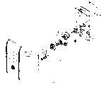
图1为根据本发明的实施方式的门锁系统的分解立体图;1 is an exploded perspective view of a door lock system according to an embodiment of the present invention;
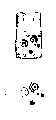
图2为根据本发明的实施方式的位于闭锁位置的门锁系统的俯视图;2 is a top view of the door locking system in a locked position according to an embodiment of the present invention;
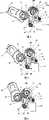
图3至图6示出根据本发明的实施方式的门锁系统的顺序操作;Figures 3 to 6 illustrate the sequential operation of a door locking system according to an embodiment of the present invention;
图7为示出了当门锁系统的锁扣装置从闭锁位置移动到解锁位置时的扭簧的操作的示意图;7 is a schematic diagram showing the operation of the torsion spring when the striker of the door lock system moves from the locked position to the unlocked position;
图8示出了当锁扣装置在闭锁位置中被干涉时的门锁系统;Figure 8 shows the door locking system when the striker is interfered in the locked position;
图9为示出了当门锁系统位于图8的状态中时的扭簧的操作的示意图;Figure 9 is a schematic diagram showing the operation of the torsion spring when the door lock system is in the state of Figure 8;
图10示出了根据本发明的实施方式的保险杆的操作;Figure 10 illustrates the operation of the bumper according to an embodiment of the invention;
图11和图12为示出了根据本发明的实施方式的支撑部分的操作的局部视图;11 and 12 are partial views showing the operation of the support part according to the embodiment of the present invention;
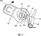
图13示出了根据本发明的实施方式的、在以强制方式打开之前的门锁系统;以及Figure 13 shows a door locking system prior to being forced open, according to an embodiment of the present invention; and
图14至图15示出了根据本发明的实施方式的门锁系统的强制打开结构。14 to 15 illustrate the forced opening structure of the door lock system according to the embodiment of the present invention.
具体实施方式Detailed ways
下面将参考附图详细描述本发明。Hereinafter, the present invention will be described in detail with reference to the accompanying drawings.
图1为根据本发明的实施方式的门锁系统的分解立体图。图2为根据本发明的实施方式的位于闭锁位置的门锁系统的俯视图。FIG. 1 is an exploded perspective view of a door lock system according to an embodiment of the present invention. 2 is a top view of the door locking system in a locked position according to an embodiment of the present invention.
参考附图,门锁系统包括:前盖1,其具有按钮部分1b和/或钥匙接触部分1a。在门锁系统中,通过由按钮部分1b或钥匙接触部分1a输入口令来执行闭锁和解锁操作。Referring to the drawings, the door lock system includes: a
紧固盖2a从锁壳体2的前侧连接至锁壳体2的内侧,以紧固内部元件。电池5嵌入锁壳体2的上部后侧中,以向门锁系统供电。控制器(未示出)控制门锁系统的全部操作,并且通常设置为印刷电路板(PCB)的形式。多个支撑肋6设置在锁壳体2的内部。旋转销7a、7b、7c和7d连接至各支撑肋6,以支撑将在下文中描述的构件。A
驱动马达10设置在锁壳体2的下部内侧。驱动马达10从电池5接收能量,并且响应控制器的闭锁信号和解锁信号、根据预定的旋转量的顺时针旋转和逆时针旋转。蜗轮12设置在驱动马达10的马达轴的端部,以作为马达轴齿轮。在本说明书中,马达轴齿轮被限定为安装在马达轴上的齿轮。The
与蜗轮12结合的驱动齿轮14和以整体地方式同轴地连接至驱动齿轮14的操作齿轮16通过旋转销7a支撑在蜗轮12的一侧上。蜗轮12的旋转通过驱动齿轮14和操作齿轮16减缓,并且被传递至旋转齿轮组20。A
旋转齿轮组20包括上旋转齿轮24和下旋转齿轮22,它们以可旋转的方式被支撑在旋转销7b的周围,还包括扭簧30,其设置在上旋转齿轮24和下旋转齿轮22之间,并将旋转力转换成要传递的弹性力。The
由于上旋转齿轮24和下旋转齿轮22以可旋转的方式通过旋转销7b支撑,因此当不存在扭簧30时,上旋转齿轮24的旋转将不影响下旋转齿轮22,并且下旋转齿轮22的旋转将不影响上旋转齿轮24。Since the upper
所述上旋转齿轮24与操作齿轮16结合,并且由此与蜗轮12一起旋转。与扭簧30的端部32可接触的第一钩件24a从上旋转齿轮24的下表面向下突出。The upper
下旋转齿轮22与闭锁装置40的齿轮42结合。下旋转齿轮可以使锁扣装置40和下旋转齿轮22一起运转。第二钩件22a从下旋转齿轮22的上表面向上突出,并且以可接触的方式设置在扭簧30的端部32。The
扭簧30设置在上旋转齿轮24和下旋转齿轮22之间,并且插入下旋转齿轮22的中心轴23中,并由下旋转齿轮22的中心轴23支撑。上旋转齿轮24的第一钩件24a和下旋转齿轮22的第二钩件22a以可接触的方式设置在扭簧30的两端32之间。The
优选的是,扭簧30的两端32彼此交叉,并且第一钩件24a和第二钩件22a设置在交叉的两端32之间。Preferably, the two ends 32 of the
因此,上旋转齿轮24与蜗轮12一起旋转,并且随后第一钩件24a挤压扭簧30的端部32的第一侧。结果,扭簧30的直径减小,并且由此上旋转齿轮24的旋转力被转化成弹性力。在这种情况下,如果第二钩件22a不受限制,即下旋转齿轮22可以旋转,则端部32的第二侧利用扭簧30的弹性力挤压第二钩件22a,从而旋转下旋转齿轮22。然而,如果第二钩件22a受到限制,即在与下旋转齿轮22结合的锁扣装置40中发生干涉,由此下旋转齿轮22不能旋转,则扭簧30的直径因上旋转齿轮24的旋转力而减小,并且由此旋转力转换成被存储的弹性能。此后,如果第二钩件22a变得不受限制,即产生在锁扣装置40中的干涉被消除,并且由此下旋转齿轮22可以旋转,则扭簧30恢复。结果,端部32的第二侧利用弹性力挤压第二钩件22a,从而使下旋转齿轮22旋转。Accordingly, the
优选的是,在锁扣装置40的闭锁位置和解锁位置中,第一钩件24a和第二钩件22a保持沿扭簧30的周向确定的一定的分隔间距,由此防止锁扣装置40移动。Preferably, in the locked position and the unlocked position of the
当通过设置在锁壳体2的左侧上的孔口3移入/移出闭锁和解锁位置时,锁扣装置40插入或脱离形成在门框中的锁口,以闭锁或解锁门。齿轮42设置在锁扣装置40的一个后侧,并且与下旋转齿轮22结合。When moving in/out of the locked and unlocked positions through the
如图中所示,锁扣装置40可以以可旋转的方式执行闭锁操作,或者可以在沿水平方向移动的同时执行闭锁操作。如果锁扣装置40包括在通过沿水平方向移动孔口3来执行闭锁操作或解锁操作的门锁系统中,则齿轮42为齿条传动类型。另一方面,如果锁扣装置40包括在通过形成在锁壳体2中的转轴43支撑并且围绕转轴43旋转的门锁系统中,并且由此插入或脱离锁口以闭锁或解锁门,则齿轮42具有圆弧形状的接合表面,并且接收下旋转齿轮22的旋转力。这将包括在本发明的权利要求书的范围内。优选的是,本发明进一步包括防盗保险杆50,这样锁扣装置40不能通过反常的解锁操作(例如通过电子钥匙接触操作和/或口令输入操作),在闭锁位置(其中锁扣装置40被插入到门框的锁口中)解锁。As shown in the drawing, the
防盗保险杆50包括:第一杆54,其转轴被插入旋转销7c,从而以可旋转的方式紧固,并且第一杆54朝向锁扣装置40的后侧延伸;以及第二杆52,其以一定的角度与第一杆54结合成整体,并且朝向上旋转齿轮24的前侧延伸。The
台阶钩46在锁扣装置40的后侧中形成有一个台阶。第一杆54的端部可以设置在台阶钩46的旋转路径上,并且当锁扣装置40从解锁位置移动至闭锁位置时,第一杆54的端部以可接触的方式将台阶钩46支撑在这个位置,从而防止锁扣装置40移动。The stepped
第二杆52朝向旋转齿轮24的前侧延伸,并且与杆驱动凸轮26的外周表面形成接触。在第二杆52中,杆驱动凸轮26的外周表面和内周表面彼此形成接触,这样第二杆52可以沿外周表面操作,从而移动第一杆54。The
弹簧60设置在防盗保险杆50的转轴上,并且向左侧(相对于图2)提供弹性力,这样防盗保险杆50的第二杆52与杆驱动凸轮26的外周表面形成接触。因此,防盗保险杆50可以与杆驱动凸轮26一起旋转。The
杆驱动凸轮26与设置在上旋转齿轮24的前侧的上旋转齿轮结合成整体并一同旋转。杆驱动凸轮26的外周表面包括具有短旋转直径的第一部分26a和具有长旋转直径的第二部分26b。即相对于上旋转齿轮24的转轴,第一部分26a具有短直径,并且第二部分26b具有长直径。优选的是,第一部分26a具有两个三角形形式的倾斜表面,并且第二部分26b具有圆弧形状的表面。The
在锁扣装置40位于闭锁位置的状态下,当锁扣装置40朝向解锁位置旋转时,第一杆54与台阶钩46形成接触,这样防止了锁扣装置40旋转。这里,第二杆52与围绕杆驱动凸轮26的外周表面的第一部分26a保持接触。相应地,当恶意的用户试图将锁扣装置40与锁口分离,从而通过在门框和门之间插入工具(例如,卡或驱动器)而将锁扣装置40移动至解锁位置时,锁扣装置40的台阶钩46和第一杆54彼此形成接触,从而防止锁扣装置40通过不恰当的方式移动。In a state where the
然而,如果驱动马达10响应正常信号旋转,并且由此其驱动力传递至上驱动齿轮24,则杆驱动齿轮26与旋转齿轮24一起旋转。结果,第二杆52与杆驱动凸轮26的第二部分26b形成接触。具有大旋转直径的第二部分26b允许第二杆52与杆驱动凸轮26一起向右旋转。结果,第一杆54也向右移动,从而移动至第一杆54不与台阶钩46形成接触的位置。相应地,如果驱动马达10在控制器的控制下旋转从而旋转上旋转齿轮24,防盗保险杆50也可以防止锁扣装置40移动。However, if the
优选的是,根据本发明的实施方式的门锁系统进一步包括用于防止当门打开时锁扣装置40向外突出的支撑部分70。Preferably, the door lock system according to the embodiment of the present invention further includes a
支撑部分70包括本体74、支撑杆72、和操作弹簧76。倾斜部分47形成在锁扣装置40的后侧,以操作支撑部分70。The supporting
本体74通过旋转销7d沿垂直于锁扣装置40的旋转方向的方向,被可旋转地支撑在锁扣装置40的下侧,并且通过向外突出于或向内插入于形成在孔口3的下侧的通孔4而旋转。支撑杆72朝向本体74的上侧延伸。当本体74突出时,支撑杆72与设置在解锁位置处的锁扣装置40的倾斜部分47形成接触,从而防止锁扣装置40旋转。然而,当本体74旋转时,支架72不再与倾斜部分47形成接触,并且由此锁扣装置40可以朝向锁扣位置旋转。The
当由于插入到旋转销7d中的操作弹簧76而使锁扣装置40位于解锁位置时,本体74接受弹性力,从而本体74突出而穿过通孔4。When the
在下文中,将详细描述本发明的门锁系统的操作。Hereinafter, the operation of the door lock system of the present invention will be described in detail.
图3至图6示出了根据本发明的实施方式的门锁系统,并且顺序示出了当驱动马达旋转时,因锁扣装置在闭锁位置的旋转而执行解锁操作的过程。3 to 6 illustrate a door lock system according to an embodiment of the present invention, and sequentially show a process of performing an unlocking operation due to rotation of a striker at a locked position when a driving motor rotates.
图3示出了在闭锁位置的门解锁系统。当门锁系统位于闭锁位置时,锁扣装置40旋转,以突出于锁壳体2的孔口3的外侧(参见图2),此外,防盗保险杆50的第二杆52与杆驱动凸轮26的第一部分26a形成接触,并且第一杆54设置在当锁扣装置40旋转时第一杆54可以与台阶钩46形成接触的位置处。Figure 3 shows the door unlocking system in the locked position. When the door lock system was in the locked position, the
在这种情况下,通过口令输出操作和/或电子钥匙接触操作执行解锁操作。此外,控制器提供电能,以使驱动马达10可以旋转预定的旋转量。In this case, the unlocking operation is performed by a password output operation and/or an electronic key contact operation. In addition, the controller supplies electric power so that the
图4示出了当驱动马达旋转的同时执行解锁操作时的门锁系统。参考图4,当驱动马达10的马达轴旋转时,蜗轮12旋转,并且由此与之结合的驱动齿轮14旋转。旋转力被传递至同轴地连接至驱动齿轮14的操作齿轮16,并且由此操作齿轮16允许所结合的上旋转齿轮24旋转。当上旋转齿轮24旋转时,下旋转齿轮22通过扭簧30旋转。因此,下旋转齿轮22的旋转力通过所结合的齿轮22传递,从而顺时针旋转锁扣装置40。在此,杆驱动凸轮26与防盗保险杆50的上旋转齿轮24一起旋转。当相对于第二杆52的接触点从第一部分26a移动至第二部分26b时,第二杆52向右移动。当第二杆52向右移动时,与之结合的第一杆54也向右移动,这样第一杆54移动至即使锁扣装置40旋转第一杆54也不与台阶钩46形成接触的位置。根据这种操作,在锁扣装置40的台阶钩46到达台阶钩46可以与第一杆54形成接触的位置之前,第一杆54移向右侧,并且由此当利用驱动马达10的旋转以正常的方式执行解锁操作时,锁扣装置40可以移动,而不会被防盗保险杆50干涉。FIG. 4 shows the door lock system when an unlocking operation is performed while the drive motor is rotating. Referring to FIG. 4 , when the motor shaft of the driving
图5示出了当驱动马达10在图4的状态中进一步旋转时的门锁系统。这里,锁扣装置40旋转,而不会被防盗保险杆50的第一杆54干涉。FIG. 5 shows the door lock system when the
图6示出了当解锁操作完成时的门锁系统。一端突出于孔口3的外侧的锁扣装置40因下操作齿轮22的旋转而向锁壳体2的孔口3内部旋转,并且位于锁壳体2的内部。结果,解锁操作完成,并且由此可以将门打开。Fig. 6 shows the door lock system when the unlocking operation is completed. The locking
当关闭门时,驱动马达10沿与门打开的方向相反的方向旋转,并且由此锁扣装置40朝向锁壳体2的孔口3外侧旋转,并且随后插入到锁口中。When the door is closed, the
图7为示出了当如图6中所示执行门锁系统的解锁操作时,扭簧的操作的示意图。为方便起见,在图7中省略了上旋转齿轮和下旋转齿轮,而仅仅示出了第一钩件和第二钩件。尽管第一钩件和第二钩件在附图中具有不同的横截面,然而本发明并不限于此。FIG. 7 is a schematic view showing the operation of the torsion spring when the unlocking operation of the door lock system is performed as shown in FIG. 6 . For convenience, the upper rotation gear and the lower rotation gear are omitted in FIG. 7 , and only the first hook and the second hook are shown. Although the first hook and the second hook have different cross-sections in the drawings, the present invention is not limited thereto.
首先,参考图7中的(a),图中示出了当门锁系统的锁扣装置位于闭锁位置时的扭簧。当驱动马达10响应诸如状态(a)中的钥匙接触等信号而旋转时,驱动力被传递,从而上旋转齿轮24旋转。First, refer to (a) in FIG. 7 , which shows the torsion spring when the locking device of the door locking system is in the locked position. When the
相应地,第一钩件24a挤压扭簧30的第一端32a,并且将旋转力转换成扭簧30的弹性力。这里,由于不存在限制扭簧30的力,因此,扭簧30通过弹性力旋转,同时扭簧30的第二端32b挤压第二钩件22a。结果,如(b)中所示,第一钩件24a和第二钩件22a沿相同的方向旋转,并且下旋转齿轮22和上旋转齿轮24沿相同的方向旋转。Accordingly, the
如(c)中所示,当上旋转齿轮24因驱动马达10的旋转而旋转至足以解锁锁扣装置40时,下旋转齿轮22也旋转以进行应对。As shown in (c), when the
在图7中的(a)和(c)中示出了根据本发明的实施方式,当锁扣装置位于闭锁位置和解锁位置时的扭簧。(a) and (c) in FIG. 7 show the torsion spring when the locking device is in the locked position and the unlocked position according to the embodiment of the present invention.
首先参考图7中的(a),在状态(a)中,锁扣装置40的端部可以被插入到锁口中,从而锁住门。然而,由于扭簧30的形状在状态(a)中不变,因此不存在防止第一钩件24a和第二钩件22a在扭簧30的两端之间略微移动的弹性力。结果,锁扣装置40可以略微的移动。另一方面,如果第一钩件24a顺时针旋转过度,并且挤压扭簧30的第二端32b,则扭簧30通过弹性力突出以允许第二钩件22a旋转。然而,由于锁扣装置40被支撑为与孔口3的下端接触,并且由此不能旋转,因此锁扣装置40牢固地固定至孔口3的下端。即由于驱动马达10沿锁扣方向过度旋转,因此锁扣装置40在闭锁位置牢固地紧固。Referring first to (a) in FIG. 7 , in state (a), the end portion of the
在图7中的(c)中示出了在与(a)的原理相同的情况下,当锁扣装置牢固地固定在解锁位置中时的扭簧。即在锁扣装置40到达解锁位置之后,如果驱动马达10沿解锁方向过度地连续旋转,则第一钩件24a逆时针旋转过度,并且由此挤压并移动扭簧30的第一端32a。在这种状态下,尽管第二钩件22a试图因扭簧30的弹性力而逆时针旋转,然而锁扣装置40不能通过支撑在锁壳体2的内部而旋转,并且由此通过弹性力牢固地紧固在解锁位置。(c) in FIG. 7 shows the torsion spring when the locker is firmly fixed in the unlocked position under the same principle as (a). That is, after the
相应地,通过允许驱动马达10比所要求的、适于旋转锁扣装置40的旋转量进一步地在闭锁位置和解锁位置之间旋转,锁扣装置40可以牢固地紧固,而不会通过弹性力在闭锁位置和解锁位置之间移动,其中所述弹性力为当第一钩件24a和第二钩件22a在闭锁位置和解锁位置之间分离时,在扭簧30中产生的弹性力。Accordingly, by allowing the
图8示出了根据本发明的实施方式,当锁扣装置在闭锁位置中被干涉时的门锁系统。图9示出了图8的扭簧的操作。Figure 8 shows the door locking system when the striker is interfered in the locked position according to an embodiment of the invention. FIG. 9 illustrates the operation of the torsion spring of FIG. 8 .
参考图8,驱动马达10响应解锁信号以预定的旋转量旋转。结果,因驱动齿轮14和操作齿轮16而与蜗轮12一起旋转的上旋转齿轮24旋转与蜗轮12的驱动马达10旋转量相对应的旋转量。杆驱动凸轮26与上旋转齿轮24一起旋转,并且由此防盗保险杆50的第一杆54移动至第一杆54不与锁扣装置40形成接触的右侧。由于下旋转齿轮22与锁扣装置40的齿轮42接合,因此下旋转齿轮22通过锁扣装置40受到限制,从而不旋转。Referring to FIG. 8, the driving
在图9中示出了在这种状态下的扭簧30的操作。当驱动马达10在状态(a)中旋转时,上旋转齿轮24开始逆时针旋转,并且随后第一钩件24a挤压扭簧30的第一端32a并且通过状态(b)逆时针旋转。结果,第一钩件24a和扭簧30的第一端32a移动至(c)的位置。The operation of the
然而,由于因下旋转齿轮22的限制而导致下旋转齿轮22的第二钩件22a不能移动,因此第二钩件22a保持在状态(a)中,而不管扭簧30的第二端32b造成的压力如何。相应地,扭簧30将其形状改变为如图(c)中所示的形状,并且通过第一钩件24a施加的旋转力被存储为扭簧30的弹性能。However, since the
在这种状态下,如果消除了锁扣装置40的干涉,扭簧30恢复,并且由此扭簧30的第二端32b挤压第二钩件22a,从而允许下旋转齿轮22逆时针旋转。结果,扭簧30变成状态(d)的情况,并且下旋转齿轮22旋转,以将锁扣装置40移动至解锁位置。In this state, if the interference of the
如果在锁扣装置40中发生干涉(例如,在门解锁的同时门被拉动),则即使驱动马达10运转,锁扣装置40也不能移动至解锁位置。在这种情况下,根据现有技术,锁扣装置40的干涉必须被消除,例如通过将门移动至其原始位置,并且随后必须通过钥匙接触操作等再次执行解锁操作。可选的是,用户必须等待,直到干涉消除,同时驱动马达保持加载。If interference occurs in the striker 40 (for example, the door is pulled while the door is unlocked), the
作为对比,根据本发明,驱动马达10旋转预定的旋转量而不管锁扣装置40的干涉,并且驱动马达10的旋转力转换成扭簧30的弹性能,并且由此被存储。此后,当锁扣装置40的干涉被消除时,锁扣装置40因扭簧30的弹性恢复力而被移动至解锁位置。结果,在驱动马达10保持加载的同时可以防止驱动马达10被损坏,并且无须麻烦用户再次执行解锁操作。In contrast, according to the present invention, the
类似地,在门锁系统的锁扣操作过程中,如果当锁扣装置40旋转时发生干涉,以与上述相同的方式,扭簧30将驱动马达10的旋转力存储为弹簧的弹性力,这样,当干涉消除时,锁扣装置40可以自动地操作。Similarly, during the locking operation of the door lock system, if interference occurs when the
图10示出了根据本发明的实施方式的保险杆的操作。这里,为了打开门,在门锁系统被解锁之后,通过将诸如卡9等额外的工具插入到门和门框之间,用户从外侧旋转锁扣装置40。Figure 10 illustrates the operation of the bumper according to an embodiment of the present invention. Here, to open the door, after the door lock system is unlocked, the user rotates the
当门锁系统位于闭锁状态时,第二杆52在倾斜表面上与杆驱动凸轮26形成接触,并且第一杆54位于旋转时第一杆54可以与台阶钩46形成接触的位置处,即第一杆54设置在台阶钩46的旋转直径处。When the door lock system is in the locked state, the
相应地,如果当杆驱动凸轮26旋转时,第二杆52试图旋转锁扣装置40同时不移动第一杆54,则第一杆54的端部与锁扣装置40的台阶钩46形成接触,从而,只有通过诸如电子钥匙接触操作等适当操作才能打开门。Correspondingly, if the
图11和图12为示出根据本发明的实施方式的门锁系统的支撑部分70的操作的部分视图。11 and 12 are partial views illustrating the operation of the
参考附图,当锁扣装置40位于解锁位置时,支撑杆72与形成在锁扣装置40的后侧的倾斜部分47形成接触,从而干涉锁扣装置40的旋转。在这种状态下,如果控制器通过钥匙接触操作或口令输入操作进行操作,并且使驱动马达40旋转预定的旋转量,则上旋转齿轮24旋转,但是下旋转齿轮22不以相同的方式旋转,其中锁扣装置40通过干涉受到限制,并且旋转力存储为扭簧30的弹性能。Referring to the drawings, when the
如果在这种状态下门被关闭,则支撑部分70的本体74与门框形成接触,并且由此沿与锁扣装置40的旋转方向垂直的方向(即本体74进入锁壳体2的内部的方向)旋转。此外,支撑杆72与倾斜部分74分离,并且由此移动至如图12所示的锁扣装置40的旋转不被干涉的位置。If the door is closed in this state, the
结果,当下旋转齿轮22因扭簧30的弹力旋转的同时,锁扣装置40朝向锁扣位置旋转,而不发生干涉。As a result, while the
在这种情况下,当在门打开的状态下,通过钥匙接触操作或口令输入操作提供门锁信号时,即使驱动马达10旋转预定的旋转量,锁扣装置40可以因支撑杆72而保持在解锁位置。当门被关闭时,锁扣装置40与支撑杆72分离,同时支撑部分70的本体74旋转,并且锁扣装置40通过扭簧30的弹性力朝向闭锁位置旋转。In this case, when the door lock signal is provided by the key touch operation or the password input operation in the state where the door is opened, even if the
因此,即使当在门打开的状态下提供了门闭锁信号之后门被关闭时,本发明可以防止门提前降低和关闭。因此,即使在提供了门闭锁信号之后用户关闭门,门可以被闭锁而无须额外的操作,从而改善了使用的便利性。在门打开的状态下,当锁扣装置40降低并且由此门被关闭时,支撑部分70用作防止锁扣装置40被损坏的保险装置。Therefore, even when the door is closed after the door lock signal is supplied in a state where the door is open, the present invention can prevent the door from being lowered and closed prematurely. Therefore, even if the user closes the door after the door lock signal is provided, the door can be locked without an additional operation, thereby improving convenience of use. In a state where the door is opened, when the
图13至图15示出了根据本发明实施方式的门锁系统的强制打开结构和操作。13 to 15 illustrate the forced opening structure and operation of the door lock system according to the embodiment of the present invention.
参考图13,锁扣装置孔44形成在锁扣装置40中。转轴43被插入到锁扣装置孔44中,并且由此锁扣装置40可以围绕转轴43旋转。根据本发明的实施方式,通孔45形成在锁扣装置40的锁扣装置孔44的横向侧中,并且允许台阶钩46的外周表面41的下部(其中防盗保险杆50的第一杆54与其接触)与锁扣装置孔44的内侧连接。即,通孔45沿与插入或脱离锁口的锁扣装置40的钩部40a相对的方向延伸,并且允许台阶钩46的下外周表面41与锁扣装置孔44的内侧连接。设置在通孔45中的强制打开销49可以强制地消除防盗保险杆50的阻断。突起49a形成在强制打开销49的外周表面。接合突起49a的多个槽口45a形成在通孔45中。由于突起49a与槽口45a接合,并且由此强制打开销49以可移动的方式紧固,因此强制打开销49可以被支撑在原始位置(参见图10)和移动位置(参见图14)。Referring to FIG. 13 , a
图13示出了当门锁系统处于正常操作状态时的强制打开销49。在强制打开销49中,设置在锁扣装置孔44的内部的第一端49b向锁扣装置孔44的内部突出,并且第二端49c与锁扣装置40的后外周表面平行。强制打开销49的第二端49c具有适当的长度,以当第一端49b被沿外周表面41的方向推动时,第二端49c推动防盗保险杆50的第一杆54,以移出台阶钩46的旋转路径。Figure 13 shows the
当门锁系统在常规状态中操作时,如图13所示,强制打开销49的第二端49c不从外周表面41突出,从而不影响锁扣装置40和防盗保险杆50的操作。When the door lock system operates in a normal state, as shown in FIG.
然而,当利用门锁系统时,由于失去钥匙或口令,或者由于电路故障不可能进行常规操作时,门锁系统可以通过操作强制打开销49而以强制的方式打开。However, when using the door lock system, the door lock system can be forcibly opened by operating the forcibly
再参考图1和图2,在门锁系统中,前盖1的钥匙接触部分1a与锁扣装置孔44位于同一直线。结果,用户可以发现锁扣装置孔44的正确位置,而无须使用额外的指示。如果门锁系统需要以强制的方式打开,则用户利用钻孔机在前盖1的钥匙接触部1a中制造孔。通过所述孔,用户可以将驱动器80插入到锁扣装置孔44中。这里,驱动装置80可以被插入到锁扣装置孔44的上部,即指向前盖1且其横向侧包括通孔45的部分。1 and 2 again, in the door lock system, the
图14示出了在钥匙接触部分1a中形成有孔且驱动器插入所述孔中的状态。当驱动器80被插入时,驱动器80的横向侧与强制打开销49的第一端49b形成接触,并且由此向锁扣装置孔44内突出的强制打开销49被朝向外周表面41推出。结果,强制打开销49的第二端49c将防盗保险杆50的第一杆54推出锁扣装置40的台阶钩46的旋转路径。位于锁扣装置孔44的中心的十字形孔为驱动器孔,驱动器80的前端插入所述驱动器孔。Fig. 14 shows a state where a hole is formed in the
当用户保持和旋转驱动器80时,锁扣装置40如图15所示的旋转,而不与防盗保险杆50形成接触。相应地,用户可以用强制的方式打开门锁系统。在门锁系统的强制打开结构,门可以用强制的方式在特定的位置打开,从而使损坏最小化。此外,由于当门被强制打开时,可以通过检测所发生的一定的冲击或操作而产生报警音,因此可以仅仅允许业主或授权用户以强制方式打开门。这样,可以使由于钥匙丢失或口令丢失造成的经济损失和时间损失最小化。When the user holds and rotates the
尽管已经描述了本发明的示例性实施方式,然而本发明不限于这些实施方式,而是可以在不脱离本发明的所附权利要求书、详细的说明书和附图的范围的情况下进行各种形式的修改。因此,显然这些修改属于本发明的范围。Although the exemplary embodiments of the present invention have been described, the present invention is not limited to these embodiments, but various modifications can be made without departing from the scope of the appended claims, detailed description and drawings of the present invention. Modification of form. Therefore, it is obvious that these modifications belong to the scope of the present invention.
工业应用industrial application
根据本发明的门锁系统,即使当发生干涉时(例如当执行闭锁和解锁操作时锁扣装置卡塞的情况下),驱动马达可以旋转预定的旋转量。因此,可以防止驱动马达过热、损坏或故障。此外,可以防止损坏用于操作驱动马达的控制器。此外,驱动马达无须操作两次,从而降低了电池消耗。According to the door lock system of the present invention, the drive motor can rotate by a predetermined amount of rotation even when interference occurs such as in the case of a locker jamming when performing locking and unlocking operations. Therefore, it is possible to prevent the drive motor from overheating, damage or failure. Furthermore, damage to the controller for operating the drive motor can be prevented. In addition, the drive motor does not have to be operated twice, thereby reducing battery consumption.
此外,本发明的门锁系统可以具有保险闭锁功能,其能够防止不通过正常的解锁操作而通过将锁扣装置与锁口分离将门恶意地打开,从而提高了产品的可靠性。In addition, the door lock system of the present invention can have a safety lock function, which can prevent the door from being maliciously opened by separating the lock device from the lock opening without a normal unlocking operation, thereby improving the reliability of the product.
此外,用于本发明的门锁系统的保险装置可以防止在门打开的状态下,当通过降低锁扣装置而关闭门时,门锁被损坏。In addition, the safety device used in the door lock system of the present invention can prevent the door lock from being damaged when the door is closed by lowering the striker in the state where the door is opened.
此外,在本发明中,当门锁系统在钥匙丢失、口令丢失或故障的情况下必须被打开时,门锁系统可以用强制的方式打开,同时使门锁系统的损坏最小化。Furthermore, in the present invention, when the door lock system must be opened in case of key loss, password loss, or failure, the door lock system can be opened in a forcible manner while minimizing damage to the door lock system.
Claims (13)
Translated fromChineseApplications Claiming Priority (2)
| Application Number | Priority Date | Filing Date | Title |
|---|---|---|---|
| KR1020050028260 | 2005-04-04 | ||
| KR1020050028260AKR101108135B1 (en) | 2005-04-04 | 2005-04-04 | Door lock device |
Publications (1)
| Publication Number | Publication Date |
|---|---|
| CN101151433Atrue CN101151433A (en) | 2008-03-26 |
Family
ID=37214936
Family Applications (1)
| Application Number | Title | Priority Date | Filing Date |
|---|---|---|---|
| CNA2006800102884APendingCN101151433A (en) | 2005-04-04 | 2006-04-04 | device for door lock |
Country Status (5)
| Country | Link |
|---|---|
| US (1) | US20090277231A1 (en) |
| JP (1) | JP2008534824A (en) |
| KR (1) | KR101108135B1 (en) |
| CN (1) | CN101151433A (en) |
| WO (1) | WO2006115335A1 (en) |
Cited By (2)
| Publication number | Priority date | Publication date | Assignee | Title |
|---|---|---|---|---|
| CN107646062A (en)* | 2015-06-02 | 2018-01-30 | 索尼公司 | Electric key lock device |
| CN112208769A (en)* | 2020-09-25 | 2021-01-12 | 中国直升机设计研究所 | Adjustable locking mechanism for accommodating and storing hook of goods hung outside helicopter |
Families Citing this family (14)
| Publication number | Priority date | Publication date | Assignee | Title |
|---|---|---|---|---|
| GB0608227D0 (en)* | 2006-04-26 | 2006-06-07 | Global Biotec Ltd | Access control means |
| WO2008066210A1 (en)* | 2006-11-27 | 2008-06-05 | Unipass Co., Ltd. | Lock device |
| KR100976818B1 (en)* | 2008-03-07 | 2010-08-20 | 민병도 | Auto door locking device for a hinged door |
| TR200801927A2 (en) | 2008-03-24 | 2009-01-21 | Vemus Endüstri̇yel Elektroni̇k Sanayi̇ Ve Ti̇caret Li̇mi̇ted Şi̇rketi̇ | Locking system with micro motor. |
| CN102134939A (en)* | 2010-01-21 | 2011-07-27 | 郭保宣 | Electronic unlocking device |
| CN102444335B (en)* | 2010-12-13 | 2013-07-31 | 上海嘉成轨道交通安全保障系统有限公司 | Door locking system for single-shaft track traffic safety door |
| AU2012255665B2 (en) | 2011-05-16 | 2013-04-18 | Allegion (Australia) Pty Ltd | A locking device |
| DE102014119252A1 (en)* | 2014-12-19 | 2016-06-23 | ABUS August Bremicker Söhne KG | Actuating device for a locking mechanism of a door or a window |
| WO2018204357A1 (en) | 2017-05-02 | 2018-11-08 | Carrier Corporation | Lead screw latch |
| KR101879753B1 (en) | 2017-11-14 | 2018-08-24 | 송정기 | Locking device for cabinet |
| SE543487E (en)* | 2019-05-17 | 2025-09-16 | Stendals El Ab | Catch mechanism with a first and a second connector for a bolt and a locking device |
| US12241282B2 (en)* | 2019-05-17 | 2025-03-04 | Stendals El Ab | Locking device |
| SE544908C2 (en)* | 2020-11-12 | 2022-12-27 | Stendals El Ab | Locking device, for mechanical and non-mechanical activation of a locking bolt, with a follower, a rod arrangement, and a play between them |
| KR102510959B1 (en)* | 2021-10-26 | 2023-03-16 | 지에프텍 주식회사 | Door lock with emergency power |
Family Cites Families (19)
| Publication number | Priority date | Publication date | Assignee | Title |
|---|---|---|---|---|
| ZA801399B (en)* | 1979-03-16 | 1981-03-25 | Chubb Lock & Safe Ltd | Cylinder locks |
| JPS57172083A (en)* | 1981-04-15 | 1982-10-22 | Nissan Motor | Door lock manipulating apparatus |
| US4685709A (en)* | 1984-05-29 | 1987-08-11 | R. R. Brink Locking Systems, Inc. | Deadlocked latch having disc and motor actuators |
| US4633687A (en)* | 1985-01-22 | 1987-01-06 | Ni Industries, Inc. | Drive mechanism for key operated electronic lock |
| US4763936A (en)* | 1986-10-20 | 1988-08-16 | General Motors Corporation | Power operated door latch |
| KR930000850B1 (en)* | 1986-12-26 | 1993-02-06 | 가부시끼가이샤 안세이고오교오 | Automotive Door Lock Device |
| US4875723A (en)* | 1988-03-03 | 1989-10-24 | General Motors Corporation | Closure latch |
| JPH0723658B2 (en)* | 1988-12-21 | 1995-03-15 | 三井金属鉱業株式会社 | Vehicle lock mechanism |
| SE463979B (en)* | 1989-06-29 | 1991-02-18 | Assa Ab | ELECTRICAL AND MECHANICAL ROAD POWERABLE LOADING DEVICE |
| FI87681C (en)* | 1990-10-24 | 1993-02-10 | Abloy Security Ltd Oy | ELEKTROMEKANISKT DOERRLAOS |
| US5219385A (en)* | 1990-12-13 | 1993-06-15 | Catwin Industrial Corporation | Lock for fire-escape door |
| US5437173A (en)* | 1993-02-18 | 1995-08-01 | Truth Division Of Spx Corporation | Window lock with indicator |
| DE19516162B4 (en)* | 1995-05-03 | 2007-07-12 | Kiekert Ag | Drive with reversible electric motor, transmission and clutch system for central locking of the vehicle door locks on a motor vehicle door |
| US5927769A (en)* | 1996-01-24 | 1999-07-27 | Pullen; John Howard | Kid's safety latch |
| KR100275404B1 (en)* | 1998-09-04 | 2000-12-15 | 엄기화 | An actuator for locking door |
| JP3592941B2 (en)* | 1998-11-24 | 2004-11-24 | 株式会社東海理化電機製作所 | Steering lock device |
| KR100341118B1 (en)* | 1999-08-28 | 2002-06-20 | 이성권 | Digital sub door lock |
| WO2001094727A1 (en)* | 2000-06-06 | 2001-12-13 | Delphi Technologies, Inc. | Cinching door latch with planetary release mechanism |
| JP4036624B2 (en)* | 2001-09-03 | 2008-01-23 | オクト産業株式会社 | Locking device |
- 2005
- 2005-04-04KRKR1020050028260Apatent/KR101108135B1/ennot_activeExpired - Fee Related
- 2006
- 2006-04-04CNCNA2006800102884Apatent/CN101151433A/enactivePending
- 2006-04-04WOPCT/KR2006/001234patent/WO2006115335A1/enactiveApplication Filing
- 2006-04-04USUS11/887,327patent/US20090277231A1/ennot_activeAbandoned
- 2006-04-04JPJP2008503969Apatent/JP2008534824A/enactivePending
Cited By (4)
| Publication number | Priority date | Publication date | Assignee | Title |
|---|---|---|---|---|
| CN107646062A (en)* | 2015-06-02 | 2018-01-30 | 索尼公司 | Electric key lock device |
| CN107646062B (en)* | 2015-06-02 | 2020-01-31 | 索尼公司 | Electric key lock device |
| CN112208769A (en)* | 2020-09-25 | 2021-01-12 | 中国直升机设计研究所 | Adjustable locking mechanism for accommodating and storing hook of goods hung outside helicopter |
| CN112208769B (en)* | 2020-09-25 | 2022-11-04 | 中国直升机设计研究所 | Adjustable locking mechanism for accommodating and storing hook of goods hung outside helicopter |
Also Published As
| Publication number | Publication date |
|---|---|
| WO2006115335A1 (en) | 2006-11-02 |
| KR20060105825A (en) | 2006-10-11 |
| US20090277231A1 (en) | 2009-11-12 |
| KR101108135B1 (en) | 2012-01-31 |
| JP2008534824A (en) | 2008-08-28 |
Similar Documents
| Publication | Publication Date | Title |
|---|---|---|
| CN101151433A (en) | device for door lock | |
| CN112840092B (en) | Locking assembly with spring mechanism | |
| US20180128017A1 (en) | Electronic deadbolt lock | |
| US9784016B1 (en) | Electronic sensor and key operated lock | |
| US12322231B2 (en) | Manual electronic deadbolt | |
| JP2007319536A (en) | Game machine | |
| CN117321279A (en) | Detection and correction of insufficient locking behavior of electronic locks | |
| JP5007198B2 (en) | Door lock device | |
| KR20180106707A (en) | Digital Door Rock | |
| KR200352026Y1 (en) | Mortise locking apparatus | |
| CN208251850U (en) | Finger-print puzzle lock with warning function | |
| TW202340593A (en) | Portable electronic lock | |
| HK1114519A (en) | Apparatus for door lock | |
| CN110847709B (en) | Lock structure and coin box | |
| KR101826692B1 (en) | Digital door lock device | |
| JP5519139B2 (en) | Door lock device | |
| JP2595277Y2 (en) | Electronic lock device for desk drawer | |
| CN113153020B (en) | Electronic sensor and key operated lock | |
| KR102703914B1 (en) | Vehicle Smart Unlock System | |
| JP2006183359A (en) | Fixture | |
| JP3423899B2 (en) | Steering lock device | |
| KR102702846B1 (en) | A handle-fixed door lock device for unlocking structure of the latch bolt | |
| US20250059798A1 (en) | Manual electronic deadbolt with egress assistance | |
| JP2005213888A (en) | Lock device | |
| JP7519086B2 (en) | Electric lock |
Legal Events
| Date | Code | Title | Description |
|---|---|---|---|
| C06 | Publication | ||
| PB01 | Publication | ||
| C10 | Entry into substantive examination | ||
| SE01 | Entry into force of request for substantive examination | ||
| REG | Reference to a national code | Ref country code:HK Ref legal event code:DE Ref document number:1114519 Country of ref document:HK | |
| C02 | Deemed withdrawal of patent application after publication (patent law 2001) | ||
| WD01 | Invention patent application deemed withdrawn after publication | Open date:20080326 | |
| REG | Reference to a national code | Ref country code:HK Ref legal event code:WD Ref document number:1114519 Country of ref document:HK |