CN101146477B - Piercing system for extracting body fluids - Google Patents
Piercing system for extracting body fluidsDownload PDFInfo
- Publication number
- CN101146477B CN101146477BCN2006800067522ACN200680006752ACN101146477BCN 101146477 BCN101146477 BCN 101146477BCN 2006800067522 ACN2006800067522 ACN 2006800067522ACN 200680006752 ACN200680006752 ACN 200680006752ACN 101146477 BCN101146477 BCN 101146477B
- Authority
- CN
- China
- Prior art keywords
- piercing
- skin
- reference element
- lancet
- movement
- Prior art date
- Legal status (The legal status is an assumption and is not a legal conclusion. Google has not performed a legal analysis and makes no representation as to the accuracy of the status listed.)
- Active
Links
Images


Classifications
- A—HUMAN NECESSITIES
- A61—MEDICAL OR VETERINARY SCIENCE; HYGIENE
- A61B—DIAGNOSIS; SURGERY; IDENTIFICATION
- A61B5/00—Measuring for diagnostic purposes; Identification of persons
- A61B5/15—Devices for taking samples of blood
- A61B5/151—Devices specially adapted for taking samples of capillary blood, e.g. by lancets, needles or blades
- A61B5/15146—Devices loaded with multiple lancets simultaneously, e.g. for serial firing without reloading, for example by use of stocking means.
- A61B5/15148—Constructional features of stocking means, e.g. strip, roll, disc, cartridge, belt or tube
- A—HUMAN NECESSITIES
- A61—MEDICAL OR VETERINARY SCIENCE; HYGIENE
- A61B—DIAGNOSIS; SURGERY; IDENTIFICATION
- A61B5/00—Measuring for diagnostic purposes; Identification of persons
- A61B5/15—Devices for taking samples of blood
- A61B5/150007—Details
- A61B5/150015—Source of blood
- A61B5/150022—Source of blood for capillary blood or interstitial fluid
- A—HUMAN NECESSITIES
- A61—MEDICAL OR VETERINARY SCIENCE; HYGIENE
- A61B—DIAGNOSIS; SURGERY; IDENTIFICATION
- A61B5/00—Measuring for diagnostic purposes; Identification of persons
- A61B5/15—Devices for taking samples of blood
- A61B5/150007—Details
- A61B5/150175—Adjustment of penetration depth
- A61B5/15019—Depth adjustment mechanism using movable stops located inside the piercing device housing and limiting the travel of the drive mechanism
- A—HUMAN NECESSITIES
- A61—MEDICAL OR VETERINARY SCIENCE; HYGIENE
- A61B—DIAGNOSIS; SURGERY; IDENTIFICATION
- A61B5/00—Measuring for diagnostic purposes; Identification of persons
- A61B5/15—Devices for taking samples of blood
- A61B5/150007—Details
- A61B5/150175—Adjustment of penetration depth
- A61B5/150198—Depth adjustment mechanism at the proximal end of the carrier of the piercing element
- A—HUMAN NECESSITIES
- A61—MEDICAL OR VETERINARY SCIENCE; HYGIENE
- A61B—DIAGNOSIS; SURGERY; IDENTIFICATION
- A61B5/00—Measuring for diagnostic purposes; Identification of persons
- A61B5/15—Devices for taking samples of blood
- A61B5/150007—Details
- A61B5/150358—Strips for collecting blood, e.g. absorbent
- A—HUMAN NECESSITIES
- A61—MEDICAL OR VETERINARY SCIENCE; HYGIENE
- A61B—DIAGNOSIS; SURGERY; IDENTIFICATION
- A61B5/00—Measuring for diagnostic purposes; Identification of persons
- A61B5/15—Devices for taking samples of blood
- A61B5/150007—Details
- A61B5/150374—Details of piercing elements or protective means for preventing accidental injuries by such piercing elements
- A61B5/150381—Design of piercing elements
- A61B5/150412—Pointed piercing elements, e.g. needles, lancets for piercing the skin
- A—HUMAN NECESSITIES
- A61—MEDICAL OR VETERINARY SCIENCE; HYGIENE
- A61B—DIAGNOSIS; SURGERY; IDENTIFICATION
- A61B5/00—Measuring for diagnostic purposes; Identification of persons
- A61B5/15—Devices for taking samples of blood
- A61B5/150007—Details
- A61B5/150374—Details of piercing elements or protective means for preventing accidental injuries by such piercing elements
- A61B5/150381—Design of piercing elements
- A61B5/150503—Single-ended needles
- A—HUMAN NECESSITIES
- A61—MEDICAL OR VETERINARY SCIENCE; HYGIENE
- A61B—DIAGNOSIS; SURGERY; IDENTIFICATION
- A61B5/00—Measuring for diagnostic purposes; Identification of persons
- A61B5/15—Devices for taking samples of blood
- A61B5/150007—Details
- A61B5/150374—Details of piercing elements or protective means for preventing accidental injuries by such piercing elements
- A61B5/150534—Design of protective means for piercing elements for preventing accidental needle sticks, e.g. shields, caps, protectors, axially extensible sleeves, pivotable protective sleeves
- A61B5/150572—Pierceable protectors, e.g. shields, caps, sleeves or films, e.g. for hygienic purposes
- A—HUMAN NECESSITIES
- A61—MEDICAL OR VETERINARY SCIENCE; HYGIENE
- A61B—DIAGNOSIS; SURGERY; IDENTIFICATION
- A61B5/00—Measuring for diagnostic purposes; Identification of persons
- A61B5/15—Devices for taking samples of blood
- A61B5/150007—Details
- A61B5/150801—Means for facilitating use, e.g. by people with impaired vision; means for indicating when used correctly or incorrectly; means for alarming
- A61B5/150832—Means for facilitating use, e.g. by people with impaired vision; means for indicating when used correctly or incorrectly; means for alarming by topography of the surface, e.g. Braille, embossed printing
- A—HUMAN NECESSITIES
- A61—MEDICAL OR VETERINARY SCIENCE; HYGIENE
- A61B—DIAGNOSIS; SURGERY; IDENTIFICATION
- A61B5/00—Measuring for diagnostic purposes; Identification of persons
- A61B5/15—Devices for taking samples of blood
- A61B5/150007—Details
- A61B5/150885—Preventing re-use
- A61B5/150916—Preventing re-use by blocking components, e.g. piston, driving device or fluid passageway
- A—HUMAN NECESSITIES
- A61—MEDICAL OR VETERINARY SCIENCE; HYGIENE
- A61B—DIAGNOSIS; SURGERY; IDENTIFICATION
- A61B5/00—Measuring for diagnostic purposes; Identification of persons
- A61B5/15—Devices for taking samples of blood
- A61B5/151—Devices specially adapted for taking samples of capillary blood, e.g. by lancets, needles or blades
- A61B5/15101—Details
- A61B5/15103—Piercing procedure
- A61B5/15107—Piercing being assisted by a triggering mechanism
- A61B5/15113—Manually triggered, i.e. the triggering requires a deliberate action by the user such as pressing a drive button
- A—HUMAN NECESSITIES
- A61—MEDICAL OR VETERINARY SCIENCE; HYGIENE
- A61B—DIAGNOSIS; SURGERY; IDENTIFICATION
- A61B5/00—Measuring for diagnostic purposes; Identification of persons
- A61B5/15—Devices for taking samples of blood
- A61B5/151—Devices specially adapted for taking samples of capillary blood, e.g. by lancets, needles or blades
- A61B5/15101—Details
- A61B5/15115—Driving means for propelling the piercing element to pierce the skin, e.g. comprising mechanisms based on shape memory alloys, magnetism, solenoids, piezoelectric effect, biased elements, resilient elements, vacuum or compressed fluids
- A61B5/15117—Driving means for propelling the piercing element to pierce the skin, e.g. comprising mechanisms based on shape memory alloys, magnetism, solenoids, piezoelectric effect, biased elements, resilient elements, vacuum or compressed fluids comprising biased elements, resilient elements or a spring, e.g. a helical spring, leaf spring, or elastic strap
- A—HUMAN NECESSITIES
- A61—MEDICAL OR VETERINARY SCIENCE; HYGIENE
- A61B—DIAGNOSIS; SURGERY; IDENTIFICATION
- A61B5/00—Measuring for diagnostic purposes; Identification of persons
- A61B5/15—Devices for taking samples of blood
- A61B5/151—Devices specially adapted for taking samples of capillary blood, e.g. by lancets, needles or blades
- A61B5/15101—Details
- A61B5/15126—Means for controlling the lancing movement, e.g. 2D- or 3D-shaped elements, tooth-shaped elements or sliding guides
- A61B5/15128—Means for controlling the lancing movement, e.g. 2D- or 3D-shaped elements, tooth-shaped elements or sliding guides comprising 2D- or 3D-shaped elements, e.g. cams, curved guide rails or threads
- A—HUMAN NECESSITIES
- A61—MEDICAL OR VETERINARY SCIENCE; HYGIENE
- A61B—DIAGNOSIS; SURGERY; IDENTIFICATION
- A61B5/00—Measuring for diagnostic purposes; Identification of persons
- A61B5/15—Devices for taking samples of blood
- A61B5/151—Devices specially adapted for taking samples of capillary blood, e.g. by lancets, needles or blades
- A61B5/15186—Devices loaded with a single lancet, i.e. a single lancet with or without a casing is loaded into a reusable drive device and then discarded after use; drive devices reloadable for multiple use
- A61B5/15188—Constructional features of reusable driving devices
- A61B5/1519—Constructional features of reusable driving devices comprising driving means, e.g. a spring, for propelling the piercing unit
- A—HUMAN NECESSITIES
- A61—MEDICAL OR VETERINARY SCIENCE; HYGIENE
- A61B—DIAGNOSIS; SURGERY; IDENTIFICATION
- A61B5/00—Measuring for diagnostic purposes; Identification of persons
- A61B5/15—Devices for taking samples of blood
- A61B5/151—Devices specially adapted for taking samples of capillary blood, e.g. by lancets, needles or blades
- A61B5/15186—Devices loaded with a single lancet, i.e. a single lancet with or without a casing is loaded into a reusable drive device and then discarded after use; drive devices reloadable for multiple use
- A61B5/15188—Constructional features of reusable driving devices
- A61B5/15192—Constructional features of reusable driving devices comprising driving means, e.g. a spring, for retracting the lancet unit into the driving device housing
- A61B5/15194—Constructional features of reusable driving devices comprising driving means, e.g. a spring, for retracting the lancet unit into the driving device housing fully automatically retracted, i.e. the retraction does not require a deliberate action by the user, e.g. by terminating the contact with the patient's skin
- A—HUMAN NECESSITIES
- A61—MEDICAL OR VETERINARY SCIENCE; HYGIENE
- A61B—DIAGNOSIS; SURGERY; IDENTIFICATION
- A61B5/00—Measuring for diagnostic purposes; Identification of persons
- A61B5/15—Devices for taking samples of blood
- A61B5/151—Devices specially adapted for taking samples of capillary blood, e.g. by lancets, needles or blades
- A61B5/15186—Devices loaded with a single lancet, i.e. a single lancet with or without a casing is loaded into a reusable drive device and then discarded after use; drive devices reloadable for multiple use
- A61B5/15188—Constructional features of reusable driving devices
- A61B5/15192—Constructional features of reusable driving devices comprising driving means, e.g. a spring, for retracting the lancet unit into the driving device housing
- A61B5/15196—Constructional features of reusable driving devices comprising driving means, e.g. a spring, for retracting the lancet unit into the driving device housing semi-automatically retracted, i.e. in which the retraction of the piercing unit requires a deliberate action by the user such as manual release of spring-biased retraction means
Landscapes
- Health & Medical Sciences (AREA)
- Life Sciences & Earth Sciences (AREA)
- Heart & Thoracic Surgery (AREA)
- Surgery (AREA)
- Biophysics (AREA)
- Pathology (AREA)
- Engineering & Computer Science (AREA)
- Biomedical Technology (AREA)
- Hematology (AREA)
- Medical Informatics (AREA)
- Molecular Biology (AREA)
- Physics & Mathematics (AREA)
- Animal Behavior & Ethology (AREA)
- General Health & Medical Sciences (AREA)
- Public Health (AREA)
- Veterinary Medicine (AREA)
- Dermatology (AREA)
- Measurement Of The Respiration, Hearing Ability, Form, And Blood Characteristics Of Living Organisms (AREA)
- Surgical Instruments (AREA)
Abstract
Description
Translated fromChinese技术领域technical field
本发明涉及一种用于从人或动物的皮肤中提取体液的刺入系统。所述体液通常是血液。但在有些应用情况下也涉及组织间隙的液体试样的提取。下文在没有限制普遍性的情况下作为举例仅涉及血液,但也用于其它可从皮肤中提取的体液。The present invention relates to a piercing system for extracting body fluids from human or animal skin. The body fluid is usually blood. However, some applications also involve the extraction of liquid samples from the interstitial spaces. The following, without limiting the generality, refer only to blood by way of example, but also to other bodily fluids which can be extracted from the skin.
这种系统包括设置用于一次性使用的(用完即丢的)、具有用于刺入皮肤中的刺针元件的刺入单元以及具有用于刺入运动的驱动装置的刺入仪器。特别适合用在一种这样的系统中的刺入单元也是本发明的主题。Such a system comprises a piercing unit provided for single use (disposable), having a lancing element for piercing the skin, and a piercing device having a drive for the piercing movement. A piercing unit particularly suitable for use in such a system is also the subject of the present invention.
背景技术Background technique
自很久以来就使用一次性的刺入单元,用于为分析诊断目的从身体部位(多数从手指或耳垂)中提取少量血液。在这方面,所述刺入单元通常称为刺血针。设置用于手动刺入的刺血针比如在美国专利3,789,830中得到说明。所述刺血针通常仅仅由经过医务培训的人员使用。但是刺入总是带来剧烈疼痛。Disposable lancing units have been used for a long time for the extraction of small amounts of blood from body parts, mostly from fingers or earlobes, for analytical diagnostic purposes. In this respect, the piercing unit is generally referred to as a lancet. A lancet provided for manual insertion is described, for example, in US Patent 3,789,830. Such lancets are generally only used by medically trained personnel. But piercing always brings severe pain.
自很久以来已使用包括刺入驱动装置的刺入仪器。所述刺入仪器构造为具有固定地集成的刺血针的一次性的结构。但是,该刺入仪器通常可多次使用并且具有一个支架,借助于该支架可以相应地使一根刺血针可更换地与所述刺入驱动装置相耦合。因为所述仪器和刺血针是彼此匹配的、由相同的生产商提供的元件,所以它被称为“刺入系统”或“血液提取系统”。Piercing instruments comprising a piercing drive have been used since a long time. The lancing device is designed as a disposable structure with a firmly integrated lancet. However, the piercing device is generally reusable and has a holder, by means of which a lancet can accordingly be exchangeably coupled to the piercing drive. Since the instrument and the lancet are matched to each other, elements supplied by the same manufacturer, it is called a "piercing system" or a "blood extraction system".
在多数情况下,弹簧用作用于所述布置在刺入仪器的外壳中的刺血针驱动装置的驱动元件。通过刺血针导向装置来保证所述刺入运动在一个预先确定的刺入行程上进行。在开发的初期,所述驱动装置的十分简单的结构十分常见,在这些结构上所述刺血针紧靠着固定在一根布置在细长的外壳中的压力弹簧的一个端部上。一种这样的刺入系统比如在美国专利4,469,110中得到公开。刺入仪器的另一种较早的结构在美国专利4,442,836中得到说明。在此所述刺血针的运动朝皮肤表面的方向直到换向点(刺入运动的推进阶段)由第一弹簧进行驱动,而第二弹簧则用作用于所述刺血针的回程运动(刺入运动的回程阶段)的驱动装置,该第二弹簧在所述第一弹簧和刺血针之间的力耦合中断之后发挥其作用。In most cases, a spring is used as the drive element for the lancet drive arranged in the housing of the lancing instrument. The piercing movement is ensured by the lancet guide over a predetermined piercing path. In the early stages of development, very simple constructions of the drive were common, in which the lancet is fastened against one end of a compression spring arranged in an elongated housing. One such piercing system is disclosed, for example, in US Patent 4,469,110. Another earlier construction of a piercing instrument is described in US Patent 4,442,836. The movement of the lancet in the direction of the skin surface up to the reversal point (advance phase of the piercing movement) is here driven by a first spring, while the second spring is used for the return movement of the lancet ( The second spring plays its role after the force coupling between the first spring and the lancet has been interrupted.
在其余的结构上,所述刺入仪器在其沿刺入方向的前面的端部上具有一个出口,所述刺血针的尖端从该出口中移出较短的时间,用于在身体部位中产生一个伤口,所述刺入仪器的前面的端部挤压在所述身体部位上。在这过程中,刺入深度由所述沿刺入方向在所述刺血针尖端在刺血针运动的换向点上所达到的位置与皮肤接触面的平面之间的间距所确定,所述皮肤接触面环状包围着所述出口并且在刺入那一刻抵靠在皮肤上。所述刺入仪器的具有皮肤接触面的前面的端部因而形成一个刺入深度基准元件,通过该刺入深度基准元件来保证所述刺入深度与预先规定的数值相应。In the rest of the structure, the piercing instrument has an outlet at its front end in the piercing direction, from which the tip of the lancet moves out for a short time for piercing the body part. A wound is created and the front end of the piercing instrument is pressed against the body part. During this process, the penetration depth is determined by the distance in the penetration direction between the position reached by the lancet tip at the reversal point of the lancet movement and the plane of the skin contact surface, so The skin contacting surface annularly surrounds the outlet and rests against the skin at the moment of penetration. The front end of the piercing instrument with the skin contact surface thus forms a piercing depth reference element by means of which it is ensured that the piercing depth corresponds to a predetermined value.
为控制所述刺入深度,通常通过以下方法来限制所述刺血针沿刺入方向的运动路程,即与所述刺血针相连接的止挡件碰到在所述刺入仪器的外壳中的对应的止挡面。这种外壳止挡结构比如在美国专利4,469,110中得到描述。在美国专利4,442,836中说明了一种具有两根弹簧的驱动装置,在该驱动装置上,通过以下方法来保证所述刺血针运动的换向点的指定的位置,即在移动行程的指定的点上中断在所述驱动弹簧和刺血针之间的力传递。In order to control the penetration depth, the movement distance of the lancet along the penetration direction is generally limited by the stopper connected to the lancet touching the housing of the penetration instrument. The corresponding stop surface in . Such housing stop structures are described, for example, in US Pat. No. 4,469,110. In U.S. Patent 4,442,836, a drive device with two springs is described, on which the specified position of the reversal point of the movement of the lancet is guaranteed by the following method, that is, at the specified position of the travel stroke At this point, the force transmission between the drive spring and the lancet is interrupted.
如果要求对血液的特定的分析数值进行定期监控,那么这种血液提取系统就没有满足应该满足的很高的要求。这尤其适用于糖尿病患者,糖尿病患者应该经常检查其血糖水平,用于通过胰岛素注射与需求(需求依赖于营养吸收、身体活动等而剧烈波动)之间的匹配来将其血糖水平尽可能稳定地保持在特定的额定极限之内。通过广泛的科学试验已经证实,借助于每天至少进行四次血液分析这样的强化疗法可以使糖尿病患者的最为严重的晚发机体损害(
这种强化疗法的前提是,血液提取产生尽可能小的疼痛。利用在美国专利5,318,584中说明的结构实现了在这方面的巨大进步,此外该结构基于这样的认识,即由血液提取引起的疼痛可以明显减少,如果如此构造所述刺入系统,使得刺入(即使在将相应的新型的一次性刺血针用于前后相连的刺入过程时)可以以此前未达到的质量得到再现。为保证这一点,使用具有驱动转子的刺血针驱动装置,一方面驱动弹簧(在驱动侧)作用于该驱动转子并且该驱动转子另一方面通过(在输出侧的)耦合机构如此与所述刺血针相耦合,从而将所述驱动转子的旋转运动转换为所期望的刺入运动。(借助于控制曲线)构造所述输出侧的耦合机构,使得所述刺血针在整个(由推进阶段和回程阶段组成的)刺入运动的过程中在实际上与所述驱动转子进行无间隙耦合并且由此完全通过所述驱动转子的相应运动来控制刺血针运动。通过这种结构一方面避免在使用具有外壳止挡(美国专利4,469,110)的驱动类型时由两个止挡之间的相互触碰引起的振动。另一方面通过刺血针与所述驱动转子之间的永久的无间隙的耦合保证在重复刺入运动时刺血针运动的换向点的可精确再现的位置,在美国专利4,442,836的驱动类型上没有达到所述可精确再现的位置。The premise of this intensive therapy is that the blood extraction causes as little pain as possible. A great advance in this respect was achieved with the structure described in U.S. Patent 5,318,584, which is also based on the realization that the pain caused by blood extraction can be significantly reduced if the piercing system is so constructed that the piercing ( Even when using correspondingly new disposable lancets for consecutive piercing procedures) can be reproduced with a previously unattainable quality. To ensure this, a lancet drive is used with a drive rotor, on the one hand a drive spring (on the drive side) acts on the drive rotor and on the other hand the drive rotor is thus connected via a coupling (on the output side) to the described The lancets are coupled to convert the rotational movement of the drive rotor into the desired piercing movement. (with the aid of a control curve) the coupling on the output side is configured such that the lancet is virtually play-free with the drive rotor during the entire piercing movement (consisting of an advancing phase and a retracting phase) Coupling and thus the control of the lancet movement is entirely through the corresponding movement of the drive rotor. On the one hand, vibrations caused by the mutual contact between two stops when using a drive type with a housing stop (US Pat. No. 4,469,110) are avoided by this construction. On the other hand, a precisely reproducible position of the reversal point of the lancet movement during repeated piercing movements is ensured by a permanent, backlash-free coupling between the lancet and the drive rotor, drive type in US Patent 4,442,836 The precisely reproducible position has not been reached.
本发明不仅仅涉及仅仅用于提取血滴以便随后用另一台仪器进行分析的刺入系统。更确切地说,本发明也尤其涉及所谓的集成的系统,利用所述集成的系统在尽可能不要使用者进行额外的操作步骤的情况下不仅提取血液,而且进行分析。由此产生额外的要求,另外这些额外要求产生于空间上的限制,如果两种功能必须安置在一个(出于操作原因尽可能小的)仪器外壳中。The present invention does not only relate to piercing systems used only to extract blood droplets for subsequent analysis with another instrument. Rather, the present invention also relates in particular to so-called integrated systems, with which blood is not only drawn but also analyzed with as little extra work steps as possible for the user. This results in additional requirements which also result from space constraints if both functions have to be accommodated in a (for operational reasons as small as possible) device housing.
在美国专利5,029,583和5,514,152中说明了集成的系统,在所述集成的系统上用刺血针来提取血液,该刺血针沿刺入方向的运动行程象在美国专利4,469,110中一样通过一个外壳止挡进行限制。在美国专利5,514,152所述情况下,借助于在仪器外壳中延伸的毛细通道将所提取的血滴输送给分析传感器。Integrated systems are described in U.S. Patents 5,029,583 and 5,514,152, on which blood is extracted with a lancet whose movement in the direction of penetration is stopped by a housing as in U.S. Patent 4,469,110. block to limit. In the case described in US Pat. No. 5,514,152, the extracted blood drop is transported to the analytical sensor by means of a capillary channel extending in the housing of the instrument.
在美国专利5,938,679中说明了一种刺入系统,该刺入系统的刺入单元可选设有毛细小管,通过所述毛细小管借助于毛细力可以将血液吸到仪器的内部。这是一种刺入系统的实例,该刺入系统的刺针元件具有一条毛细通道,通过该毛细通道可以将体液从皮肤传输到刺入单元的内部。一种这样的刺入系统的另一个实例在美国专利申请US2003/0018282 A1中得到说明。在该专利中,所述刺入单元不仅包括刺入皮肤中的、具有适合于输送试样的毛细通道的刺针,而且包括一个包含试剂的证明区域。一种这样的刺入单元同时具有一个用于所述试样的(比如构造为毛细活性的吸入层和/或空心室)的接收区域并且优选也包含分析所必需的试剂,以下将这样的刺入单元称为“微型取样器”。有关更详细的关于微型取样器的细节,请参照所提到的美国专利申请以及其中援引的文件,尤其美国专利5,801,057。除了这里所说明的特点之外,在本发明的框架内可以使用不同结构的微型取样器。US Pat. No. 5,938,679 describes a piercing system whose piercing unit is optionally provided with capillaries, through which blood can be sucked into the interior of the device by means of capillary force. This is an example of a lancing system, the lancing element of which has a capillary channel through which bodily fluids can be transported from the skin to the interior of the lancing unit. Another example of one such piercing system is described in US patent application US2003/0018282 A1. In this patent, the piercing unit comprises not only a piercing needle piercing the skin with a capillary channel suitable for delivering the sample, but also a proof area containing reagents. A piercing unit of this type has at the same time a receiving area for the sample (for example configured as a capillary-active suction layer and/or a hollow chamber) and preferably also contains the reagents necessary for the analysis. The input unit is called a "micro sampler". For more detailed details on microsamplers, reference is made to the cited US patent applications and documents cited therein, especially US patent 5,801,057. In addition to the features described here, microsamplers of different designs can be used within the framework of the invention.
本发明一般涉及不同类型的刺入系统,其中所述刺入皮肤中的刺针元件可以构造为实心的刺针(就象在所提到的刺血针上一样)或者构造为毛细针(具有敞开的毛细管或者构造为封闭的空心针)。只要涉及刺血针或其它更加特殊的实施方式,那它就是示范性的并且没有限制普遍性。所解释的内容在原则上也适用于其它的设计方案。The present invention generally relates to different types of piercing systems, wherein the lancet element piercing the skin can be configured as a solid lancet (as on the mentioned lancet) or as a capillary needle (with an open capillary or as a closed hollow needle). As far as lancets or other more specific embodiments are concerned, it is exemplary and not limiting of generality. What has been explained also applies in principle to other configurations.
发明内容Contents of the invention
在此基础上,本发明的任务是提供一种刺入系统,在该刺入系统上以改进的方式来保证可再现的刺入深度并且该刺入系统尤其适合应用在集成的分析系统中。On this basis, the object of the present invention is to provide a piercing system with which a reproducible piercing depth is ensured in an improved manner and which is especially suitable for use in an integrated analysis system.
该任务通过一种用于从人或动物的皮肤中提取体液的刺入系统得到解决,该刺入系统具有一次性的刺入单元以及刺入仪器,其中所述刺入单元具有用于刺入皮肤中的刺针元件,所述刺入仪器包括刺入驱动装置,通过该刺入驱动装置来驱动借助于耦合机构与所述刺入驱动装置相耦合的刺入单元的刺入运动,其中This task is solved by a piercing system for extracting body fluids from human or animal skin, which piercing system has a disposable piercing unit and a piercing instrument, wherein the piercing unit has a device for piercing A needle element in the skin, the piercing device comprising a piercing drive via which a piercing movement of a piercing unit coupled to the piercing drive by means of a coupling mechanism is driven, wherein
-在所述刺入运动的推进阶段中,所述刺针元件沿预先确定的刺入行程沿刺入方向移动,直至其尖端刺入皮肤中并且在所述刺入运动的回程阶段中所述刺针元件在到达一个与在皮肤中的刺入深度相应的换向点之后再次拉回,- in the advancing phase of the piercing movement, the lancing element moves along a predetermined piercing stroke in the piercing direction until its tip pierces the skin and in the retracting phase of the piercing movement the piercing needle The element is pulled back again after reaching a reversal point corresponding to the penetration depth in the skin,
-借助于具有皮肤接触面的刺入深度基准元件来保证刺入深度的预先给定的数值,并且- ensuring a predetermined value of the penetration depth by means of a penetration depth reference element having a skin contact surface, and
-通过沿刺入方向在所述皮肤接触面和所述针尖在刺入运动的换向点上的位置之间的间距来确定所述刺入深度的预先给定的数值,- determining the predetermined value of the penetration depth via the distance in the penetration direction between the skin contact surface and the position of the needle tip at the reversal point of the penetration movement,
其中所述刺入深度基准元件如此与所述刺针元件相连接并且与所述驱动装置相耦合,使得其Wherein the penetration depth reference element is connected to the lancet element and coupled to the drive device such that it
-至少在所述推进阶段的一段中与所述刺针元件一同移动,并且- move together with said lancing element at least during a portion of said advancing phase, and
-至少在所述刺入运动的换向点上沿刺入方向相对于所述刺针元件具有指定的纵向位置。- having a defined longitudinal position in the piercing direction relative to the lancing element at least at a reversal point of the piercing movement.
一次性的用于从人或动物的皮肤中提取体液的刺入单元也是本发明的主题,该刺入单元尤其作为一种按前述权利要求中任一项所述的系统的组成部分,具有用于沿与针尖的定向相应的刺入方向刺入皮肤中的刺针元件以及刺入深度基准元件,通过该刺入深度基准元件通过以下方法限制刺针在皮肤中的最大刺入深度,即所述刺入深度基准元件的皮肤接触面抵靠在皮肤上,由此保证所述刺入深度的预先给定的数值,其中沿刺入深度基准元件的刺入方向相对于所述刺针元件的纵向位置以及由此在皮肤接触面和针尖之间的间距可以改变以调节预先给定的刺入深度。Disposable piercing units for extracting body fluids from the skin of humans or animals are also the subject of the present invention, in particular as part of a system according to any one of the preceding claims, having the function of A lancet element for piercing into the skin in a piercing direction corresponding to the orientation of the needle tip and a piercing depth reference element, by means of which the maximum piercing depth of the piercing needle in the skin is limited by the fact that the piercing The skin-contacting surface of the penetration depth reference element rests on the skin, thereby ensuring a predetermined value of the penetration depth, wherein the longitudinal position of the penetration depth reference element relative to the needle element in the penetration direction and As a result, the distance between the skin contact surface and the needle tip can be varied in order to set a predetermined penetration depth.
在常见的刺入系统上,所述刺入深度基准元件由一个固定地与外壳相连接的部件通常是刺入仪器的外壳的前面的端部所构成,与所述常见的刺入系统相反,对本发明来说独特的是,所述刺入深度基准元件至少在所述推进阶段的一段中与所述刺针元件一同引动。对刺入深度来说具有决定作用的是所述针尖相对于皮肤接触面的“伸出长度”,而所述皮肤接触面则设置在所述一同引动的刺入深度基准元件的沿刺入方向在前面的端部上。这个伸出长度优选可以调节,以便能够根据使用者的需求调节不同的刺入深度。Contrary to conventional piercing systems in which the penetration depth reference element consists of a part fixedly connected to the housing, usually the front end of the housing of the piercing instrument, Unique to the invention is that the penetration depth reference element is driven together with the lancet element at least during a section of the advancing phase. Determining the penetration depth is the "extrusion length" of the needle tip relative to the skin contact surface which is arranged in the penetration direction of the cooperating penetration depth reference element on the front end. This protruding length is preferably adjustable, so that different penetration depths can be adjusted according to the needs of the user.
所述刺入仪器可以是一种设置用于一次性使用的(用完即丢的)产品,其中在这种情况下所述刺入单元优选不可分开地(通过所述耦合机构)与所述刺入驱动装置相连接。但是,优选所述刺入仪器可多次使用并且具有一个支架,借助于该支架可以每次将一个一次性的刺入单元可更换地与所述刺入驱动装置相耦合。The piercing device may be a product designed for single use (disposable), wherein in this case the piercing unit is preferably inseparable (via the coupling mechanism) from the The piercing drive is connected. Preferably, however, the piercing device is reusable and has a holder by means of which a single-use piercing unit can be exchangeably coupled to the piercing drive each time.
就象在下文中还要详细解释的一样,按照本发明的一种优选的实施方式,所述刺针伸出长度的可调节性通过以下方法得到实现,即所述刺入仪器包括一方面用于所述刺针元件并且另一方面用于所述刺入深度基准元件的分开的接合器。“接合器”这一概念在这方面一般是指连接件,通过该连接件来传递力。就象还要在下文中详细解释的一样,如果所述接合器仅仅在一个运动方向上(单向地)起作用,这对本发明的某些实施方式来说已经足够。但是优选至少所述刺针元件接合器在两个方向上起作用。在任何情况下,所述接合器包括一个具有止挡的定位件,所述止挡如此与所述刺针元件或者说刺入深度基准元件的对应的止挡共同作用,使得所述刺针元件或者说刺入深度基准元件至少在刺入运动的换向点上的纵向位置通过止挡面的接触来确定。所述刺针伸出长度由两个定位件沿刺入方向的相对位置所确定并且由此可以通过这个相对位置的变化进行调节。As will be explained in more detail below, according to a preferred embodiment of the present invention, the adjustability of the protruding length of the lancet is achieved in that the piercing instrument includes, on the one hand, a Separate adapter for the lancet element and on the other hand for the penetration depth reference element. The term “coupling” in this context generally refers to a connecting piece via which force is transmitted. As will be explained in more detail below, it is sufficient for some embodiments of the invention if the clutch acts only in one direction of movement (unidirectionally). Preferably, however, at least the needle element adapter acts in two directions. In any event, the adapter comprises a positioning element with a stop which cooperates with a corresponding stop of the lancet element or penetration depth reference element in such a way that the lancet element or The longitudinal position of the penetration depth reference element at least at the reversal point of the penetration movement is determined by the contact of the stop surface. The protruding length of the lancet is determined by the relative position of the two positioning elements in the piercing direction and can thus be adjusted by changing this relative position.
按照一种实施方式,所述刺针伸出长度在刺入运动开始前进行调节,并且而后至少一直在到达所述换向点之前因此在所述刺入运动的推进阶段中保持恒定。其结果是,所述刺入深度基准元件在推进阶段中以和所述刺针元件相同的速度移动,也就是与该刺针元件同步移动。按照其它的实施方式,所述刺入单元的两个元件的相对纵向位置还在推进阶段中改变。在任何情况下,这个相对纵向位置在所述刺入运动到达换向点的那一时刻必须具有一个指定的数值,该数值相当于所述刺入深度的预先确定的数值。According to one specific embodiment, the projecting length of the lancet is adjusted before the start of the piercing movement and then remains constant at least until the reversal point is reached during the advancing phase of the piercing movement. As a result, the penetration depth reference element moves at the same speed as, ie synchronously with, the lancing element during the advancing phase. According to other embodiments, the relative longitudinal position of the two elements of the piercing unit is also changed during the advancing phase. In any case, this relative longitudinal position must have a specified value at the moment when the piercing movement reaches the reversal point, which corresponds to a predetermined value of the piercing depth.
按本发明所述刺入深度基准元件在刺入运动中以其皮肤接触面一同引动,这一事实并不意味着在按本发明的仪器上不存在固定在仪器上的皮肤接触面。更确切地说,按照一种优选的实施方式-就这点而言与公知的系统相一致-在所述刺入仪器的前面的端部上有一个第二皮肤接触面,该第二皮肤接触面环形包围着一个外壳开口并且利用该第二皮肤接触面在使用时将所述刺入仪器朝皮肤挤压。但与公知的仪器相反,这个外壳-皮肤接触面不用作刺入深度基准。所述刺入深度基准由所述基准元件-皮肤接触面构成。The fact that the penetration depth reference element according to the invention is moved along with its skin contact surface during the penetration movement does not mean that the device according to the invention does not have a skin contact surface fastened to the device. Rather, according to a preferred embodiment - in this respect consistent with known systems - there is a second skin-contacting surface at the front end of the piercing instrument, which contacts the The surface ring surrounds a housing opening and the piercing instrument is pressed against the skin by means of the second skin-contacting surface during use. However, contrary to known devices, this housing-skin contact surface is not used as a reference for the penetration depth. The penetration depth reference is formed by the reference element-skin contact surface.
所述被外壳-皮肤接触面包围的外壳开口优选具有一个较大的比如至少3毫米优选至少5毫米的直径。一个这样的较大的开口能够实现附加的功能,所述附加的功能尤其在集成的系统中对于所述分析所必需的血样的接集来说是有利的。在挤压仪器时,皮肤由于其弹性会朝所述较大的开口里面拱入。皮肤在何种程度上朝所述外壳开口拱入取决于不同的因素,尤其取决于挤压压力及皮肤的弹性。由此产生皮肤表面的位置变化,该变化在此称为“Z-变化”。在本发明的基础上,尽管存在这种Z-变化也可以实现刺入深度的很好的可再现性。The housing opening surrounded by the housing-skin contact surface preferably has a larger diameter, for example at least 3 mm, preferably at least 5 mm. Such a larger opening enables additional functions which are advantageous, especially in integrated systems, for the collection of the blood sample required for the analysis. When the instrument is squeezed, the skin arches into the larger opening due to its elasticity. The extent to which the skin arches towards the housing opening depends on various factors, in particular on the compression pressure and the elasticity of the skin. This results in a change in the position of the skin surface, which is referred to herein as a "Z-change". On the basis of the invention, a very good reproducibility of the penetration depth can be achieved despite this Z-variation.
按照一种优选的实施方式,所述刺入仪器设有一个“升程补偿机构”,通过该升程补偿机构所述刺入运动的换向点至少部分地与皮肤表面的相应位置相匹配,并且由此至少部分地对在使用刺入系统时出现的Z-变化进行补偿。因此,用于匹配刺入运动的装置称为升程补偿机构,通过该装置使所述刺入运动的换向点的纵向位置至少近似地与所述皮肤表面的相应的位置相匹配。所述升程补偿机构因此也可以称为升程匹配机构。也可以使用不同的设计方案:According to a preferred embodiment, the piercing instrument is provided with a "lift compensation mechanism", by which the reversal point of the piercing movement is at least partially matched to the corresponding position of the skin surface, Z-changes that occur when using the piercing system are thus at least partially compensated for. The device for adapting the piercing movement is therefore referred to as a lift compensation mechanism, by means of which the longitudinal position of the reversal point of the piercing movement is at least approximately adapted to the corresponding position of the skin surface. The lift compensation device can therefore also be referred to as a lift adaptation device. A different design scheme is also possible:
-一种结构称为“主动受控制的升程补偿机构”,在该结构上(比如用机械的、电子的或光电子的器件)探测所述皮肤表面的相应的位置,并且所述刺入运动(在推进阶段之前或推进阶段中)通过作用于所述刺入驱动装置、作用于该刺入驱动装置在所述刺入仪器中的定位或作用于所述耦合机构的控制件与所述皮肤表面的相应的位置相匹配。- a structure called "actively controlled lift compensation mechanism", on which (such as with mechanical, electronic or optoelectronic devices) the corresponding position of the skin surface is detected, and the piercing movement (before or during the advancing phase) by acting on the piercing drive, on the positioning of the piercing drive in the piercing instrument or on the control of the coupling mechanism and the skin The corresponding positions of the surfaces are matched.
-作为替代方案,所述升程补偿机构可以借助于一个有弹性的元件来实现,所述有弹性的元件引起所述刺入运动的“缓冲”。这个有弹性的元件可以是所述刺入驱动装置的组成部分或者所述在刺入驱动装置和刺血针之间的耦合机构的组成部分。但是,也可以通过所述刺入驱动装置的有弹性的支承来实现缓冲。尤其金属弹簧适合用作有弹性的元件,但是也可以使用由弹性体的材料包括橡胶制成的有弹性的元件。- As an alternative, the lift compensation mechanism can be realized by means of an elastic element which brings about a "damping" of the piercing movement. This elastic element can be a component of the piercing drive or of the coupling between the piercing drive and the lancet. However, damping can also be achieved by elastic mounting of the piercing drive. Metal springs are especially suitable as elastic elements, but elastic elements made of elastomeric materials, including rubber, can also be used.
-所述升程补偿机构也可以借助于摩擦接合器来实现,在该摩擦接合器中两个接合元件如此借助于摩擦力相连接,使得其能够将力沿刺入运动的方向传递,但是在超过所述作用于接合器的力的极限值时可以如此相对于彼此移动,从而中断沿刺入运动的方向的力传递。- the lift compensation mechanism can also be realized by means of a friction clutch, in which two engagement elements are connected by means of friction in such a way that they can transmit force in the direction of the piercing movement, but in When the limit value of the force acting on the clutch is exceeded, they can be moved relative to one another in such a way that the transmission of force in the direction of the piercing movement is interrupted.
这些设计原理也可以彼此组合使用。These design principles can also be used in combination with each other.
本发明的一个重要优点在于,该发明能够以非常节省空间的和在机械上比较简单的结构来实现可以很好再现的刺入深度。由此,本发明特别适合于集成的系统,在所述集成的系统上出于上述原因致力于尽可能紧凑的结构。通过比较简单的结构,能够以低廉的成本进行制造。An important advantage of the invention is that it enables a very reproducible penetration depth with a very space-saving and mechanically relatively simple construction. The invention is therefore particularly suitable for integrated systems in which, for the above-mentioned reasons, the aim is to be as compact as possible. With a relatively simple structure, it can be manufactured at low cost.
所述刺入深度的可再现性在很大程度上不依赖于所述刺入驱动装置的结构,由此产生另一优点。本发明可以结合完全不同的刺入驱动装置方案来实现。尤其所述刺入运动的驱动速度及其它细节可以与相应的要求相匹配。在必要的情况下,可以如此构造所述驱动装置,使得所述刺入单元在刺入之后迅速拉回并且由此为接下来的分析功能尤其为将试样接纳在分析元件中提供空间。The reproducibility of the penetration depth is largely independent of the design of the penetration drive, which results in a further advantage. The invention can be implemented in conjunction with completely different piercing drive solutions. In particular, the drive speed and other details of the piercing movement can be adapted to the respective requirements. If necessary, the drive device can be designed in such a way that the piercing unit is quickly retracted after piercing and thus provides space for subsequent analysis functions, in particular for receiving the sample in the analysis element.
对于本发明的多种设计方案来说,优选使用刺入驱动装置,在该刺入驱动装置上一个固定的(不是有弹性的)驱动元件从初始位置移入最终位置中并且所述驱动元件的这种运动借助于耦合机构变换为刺入运动。所述驱动元件优选是围绕着中心轴线旋转的转子,但是其它驱动元件比如摇杆或肘杆也得到公开并且-依赖于具体情况下的要求-适合于本发明。所述驱动元件的运动借助于弹力或用其它公知的手段比如电动方式或电磁方式进行。For various configurations of the present invention, it is preferred to use a piercing drive, on which a fixed (not elastic) drive element is moved from the initial position into the final position and this This movement is transformed into a piercing movement by means of a coupling mechanism. The drive element is preferably a rotor rotating about a central axis, but other drive elements such as rockers or toggle levers are also known and - depending on the requirements of the particular case - suitable for the invention. The movement of the drive element takes place by means of spring force or by other known means such as electrodynamically or electromagnetically.
在任何情况下,所述刺入驱动装置产生所述刺针元件在初始位置和所述刺入运动的换向点之间的平移运动。在所述刺入单元的运动的这些点之间的间距称为所述刺入运动的升程。In any case, the piercing drive produces a translational movement of the lancing element between an initial position and a reversal point of the piercing movement. The distance between these points of movement of the piercing unit is referred to as the lift of the piercing movement.
附图说明Description of drawings
下面借助于在附图中示出的优选的实施方式对本发明进行更详细解释。在附图中示出的特征可以单个使用或者组合使用,用于提供本发明优选的设计方案。其中:The invention is explained in more detail below with the aid of preferred embodiments shown in the drawings. The features shown in the drawings can be used individually or in combination to provide preferred embodiments of the invention. in:
图1是刺入系统的第一实施方式的对本发明重要的部件的示意剖面图;Figure 1 is a schematic sectional view of the components important to the present invention of a first embodiment of the piercing system;
图2是所述刺入系统的在四个使用位置a到d中的与图1相应的视图;FIG. 2 is a view corresponding to FIG. 1 of the piercing system in four use positions a to d;
图3是适合于本发明的具有升程补偿机构的刺入驱动装置的第一实施方式的示意侧视图;3 is a schematic side view of a first embodiment of a piercing drive device with a lift compensation mechanism suitable for the present invention;
图4是适合于本发明的刺入驱动装置的第二实施方式的示意侧视图;Figure 4 is a schematic side view of a second embodiment of a piercing drive suitable for the present invention;
图5是具有升程补偿机构的另一种实施方式的刺入系统的四个使用位置;Fig. 5 is the four use positions of the piercing system with another embodiment of the lift compensation mechanism;
图6是按本发明的刺入单元的示意剖面图;Figure 6 is a schematic sectional view of a piercing unit according to the present invention;
图7是按本发明的刺入单元的另一种实施方式的示意剖面图;Figure 7 is a schematic sectional view of another embodiment of the piercing unit according to the present invention;
图8是按图6的刺入单元的刺血针固定座的俯视图;Figure 8 is a top view of the lancet holder of the piercing unit according to Figure 6;
图9是所述按图6的刺入单元的刺血针的刺血针本体的下侧面的俯视图;9 is a plan view of the underside of the lancet body of the lancet of the piercing unit according to FIG. 6;
图10是按本发明的、微型取样器形式的刺入单元的另一种实施方式的侧视图以及所属的刺入仪器的耦合机构的侧视图,所述微型取样器与该刺入仪器一起形成一个刺入系统;10 is a side view of another embodiment of a piercing unit according to the invention in the form of a microsampler with which the microsampler is formed together with a coupling mechanism of the associated piercing device. a piercing system;
图11是图10所示部件的正视图;Figure 11 is a front view of the components shown in Figure 10;
图12是图10所示微型取样器的从下面看的视图;Figure 12 is a view from below of the microsampler shown in Figure 10;
图13是图10所示微型取样器的从上面看的视图;Figure 13 is a view from above of the microsampler shown in Figure 10;
图14是类似于图11的微型取样器在四个不同使用位置a到d中的侧视图;Figure 14 is a side view of a microsampler similar to Figure 11 in four different use positions a to d;
图15是对按本发明的刺入系统来说典型的刺入运动的行程-时间-图;Fig. 15 is the stroke-time-diagram of typical piercing motion according to the piercing system of the present invention;
图16是公知的、具有盒装刺血针的刺入系统的一部分的透视图;Figure 16 is a perspective view of a portion of a known piercing system with a cartridge of lancets;
图17是本发明的一种具有盒装刺入单元的实施方式的一部分的剖面图;Figure 17 is a cross-sectional view of a portion of an embodiment of the present invention having a piercing unit in a box;
图18是按本发明的无外壳的刺入系统的另一种实施方式的透视图;Figure 18 is a perspective view of another embodiment of the piercing system without a housing according to the present invention;
图19是图18所示刺入系统的剖面图;Figure 19 is a cross-sectional view of the piercing system shown in Figure 18;
图20是另一种对按本发明的刺入系统来说典型的刺入运动的行程-时间-图;Fig. 20 is another kind of stroke-time-diagram of typical piercing motion according to the piercing system of the present invention;
图21是类似于图18的刺入系统在四个使用位置A到D中的示意侧视图;Figure 21 is a schematic side view of a piercing system similar to Figure 18 in four use positions A to D;
图22是按本发明的无外壳的刺入系统的另一种实施方式的侧视图;Figure 22 is a side view of another embodiment of the piercing system without a housing according to the present invention;
图23是图22所示刺入系统的纵剖面图;Figure 23 is a longitudinal sectional view of the piercing system shown in Figure 22;
图24是图22所示刺入系统的透视图;Figure 24 is a perspective view of the piercing system shown in Figure 22;
图25是按本发明的刺入系统的另一种实施方式的侧视图(部分为剖面图);Figure 25 is a side view (partially in section) of another embodiment of the piercing system according to the present invention;
图26是刺针元件带的不按比例的横截面示意图;Figure 26 is a schematic cross-sectional view, not to scale, of a lancing element strip;
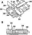
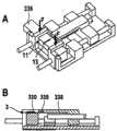
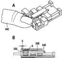
图27到30是按本发明的刺入系统的另一种实施方式在四个使用位置中的相应的透视图(A)和侧视图,部分为剖面图(B);27 to 30 are corresponding perspective views (A) and side views, partially in section (B), of another embodiment of the piercing system according to the present invention in four positions of use;
图31到33是按本发明的刺入系统的另一种实施方式在三个使用位置中的部分-横截面示意图。31 to 33 are partial schematic cross-sectional views of another embodiment of the piercing system according to the invention in three positions of use.
只要用单词“前面”和“后面”来表示部件的定位,那就是与刺入方向有关。比如因此所述刺入单元或刺入仪器的、用于刺入的端部就称为前端并且与其对置的端部就称为后端。名词“纵向”和“纵向位置”则表示所述刺入运动的空间方向,该空间方向也称为Z-方向,并且在普通的细长的(“铅笔状”)刺入仪器上与其主轴线相一致。As long as the words "front" and "rear" are used to indicate the orientation of the components, that is with respect to the direction of penetration. For example, the end of the piercing unit or the piercing instrument for piercing is thus referred to as the front end and the end opposite it as the rear end. The terms "longitudinal" and "longitudinal position" then denote the spatial direction of the piercing movement, which is also called the Z-direction, and which on ordinary elongated ("pencil-like") piercing instruments is aligned with its main axis consistent.
具体实施方式Detailed ways
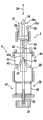
图1和2示出了刺入系统的对按本发明的功能来说重要的部件,也就是说一次性的刺入单元1以及没有总体示出的刺入仪器2的部件。这些部件首先形成耦合机构3用于将刺入单元1与在这些图中仅仅以符号示出的刺入驱动装置4相连接。1 and 2 show the components of the lancing system that are essential for the function according to the invention, that is to say the disposable lancing
所述刺入单元1具有两个主要组成部分,也就是说一个在总体上用6表示的具有刺针元件本体7及刺针8的刺针元件以及具有皮肤接触面11及基准元件本体12的刺入深度基准元件10,所述基准元件本体12从所述皮肤接触面11向下延伸并且将所述刺针元件6的本体件7包围。如果所述刺针8处于在图1和2a中示出的使用位置中,那么其尖端13就被一个消毒保护罩14所包围,该消毒保护罩14优选由一种塑料材料制成,该塑料材料将所述针尖13紧密包围并且由此在所述刺入单元1存放期间保证该针尖13的无菌性。The piercing
在图1和2a中示出了所述刺入单元1的交货状态。在这个状态中,所述刺针元件6通过固定件15固定在所述基准元件本体12内部的一个指定的纵向位置中,其中如此构造所述固定件15(比如构造为所示出的、啮合在合适的空隙中的榫舌的形式),从而在按下文解释使用所述刺入单元时(或者至迟在刺入运动过程中)松开所述固定状态,如果所述刺针元件6有必要相对于所述刺入深度基准元件10进行相对移动。The delivery state of piercing
所述耦合机构3具有分开的用于所述刺入单元1的元件的接合器,也就是一个刺针元件接合器16以及一个基准元件接合器17。每个接合器有一个定位件16a或者说17a,所述定位件16a或者说17a具有止挡16b或者说17b,所述止挡16b或者说17b如此与所述刺针元件6或者说刺入深度基准元件10的对应的止挡6b或者说10b共同作用,从而在所述元件的耦合状态中这些元件的相应的至少在所述刺入运动的换向点上的纵向位置通过这些止挡的接触来确定。The
在所示出的情况下,所述刺针元件接合器16的定位件16a由连接杆19的加粗头部18构成,所述刺针元件定位件16a通过所述连接杆19与所述刺入驱动装置4相连接。所述头部18的前面的限制面形成所述止挡16b。所述刺针元件6的对应的止挡16b在所示出的结构中由所述刺针8的后面的端部构成。所述刺针元件接合器的所示出的结构从US 2004/0260325中得到公开,从该专利文件中还可得知其它信息。In the case shown, the
一个处于圆柱形穿孔23中的滑动体22用作所述基准元件接合器17的定位件17a。该滑动体22具有一个带有内螺纹20的轴向穿孔,所述设有相应的外螺纹21的连接杆19旋入所述内螺纹20中。通过由这些部件形成的定位件16a、17a的相对旋转,可以改变所述定位件16a、17a相对于彼此的纵向位置。优选所述(这里由滑动体22形成的)基准元件-定位件17a不可相对转动地并且可轴向移动地得到支承,而所述(这里由定位杆19的头部18形成的)刺针元件-定位件16a与一个部件(这里是连接杆19)相连接,该部件的位置可通过围绕着自身的轴线的旋转在所述基准元件-定位件17a的内部沿纵向改变。A sliding
在按照图1通过双箭头24示出的、由推进阶段及回程阶段组成的刺入运动中,所述滑动体22及穿孔23作为导向装置起作用,通过该导向装置来保证精确地按照预先给定的刺入方向进行所述刺入运动。In the piercing movement shown by the
所述基准元件接合件在所示出的情况下构造为止动钩结构。在所述基准元件本体12的在径向方向上可弹性变形的、后面的端部上构造了止动钩25,所述止动钩25在使用所述刺入单元1时啮合在一个相应的、设置在所述滑动体22的前端面上的止动轮廓26中。在此,所述止挡17b或者说10b由所述滑动体22的端面构成或者说由所述基准元件本体12的最后面的端部构成。In the case shown, the reference element engagement part is designed as a locking hook structure. On the radially elastically deformable rear end of the
所述刺针元件接合器16以及基准元件接合器17在总体上形成一个支架27,借助于该支架27可以相应地将一个一次性的刺入单元1可更换地与一个可多次使用的刺入仪器2的刺入驱动装置4相耦合。在图2的分图a和b中示出了将一个刺入单元1装入所述支架27中的情况。The
为方便操作,所述刺入单元1具有一个比如以塑料注塑法喷注的装入辅助件30,在装入之后可由使用者将该装入辅助件30旋下。在装入时,将所述刺入单元1从图2a所示的初始位置置于图2b所示的位置中,在该位置中不仅所述刺针元件接合器16而且所述基准元件接合器17都已闭合,并且在所述连接杆19和刺针元件本体7之间或者说在所述滑动体22和基准元件本体12之间形成一种在两个轴向方向上(双向)起作用的固定的连接。在此,一个设置在所述刺针元件本体7的后面的端部上的凹处31包围着所述连接杆19的头部18。所述止动钩25与相应的止动轮廓26咬合。从分图a和b的比较中可以看出,通过所述刺针元件6相对于所述刺入深度基准元件10的相对运动将所述消毒保护罩14向后推动离开所述针尖13。For ease of handling, the piercing
优选在装入所述刺入单元1之前就已对所述止挡16b在纵向方向上相对于所述止挡17b的间距进行了调节,从而在装入过程中(在松开所述固定件15的情况下)将所述刺针元件6向前推,直到所述针尖13从皮肤接触面11中移出来并且所述伸出距离相当于所期望的刺入深度。但是也可以实现一些实施方式,在这些实施方式中在装入所述刺入单元之后才对刺入深度进行调节。在任何情况下都可以通过改变定位件16a、17a的相对纵向位置来调节所期望的精确的刺入深度。如果在刺入运动之前进行调节,那么所述针尖13相对于皮肤接触面11的伸出距离在刺入运动过程中保持恒定,并且所述刺入单元的位置在刺入运动的任一时刻都由所述连接杆19的相应位置来确定。Preferably, the spacing of the
图2c示出了在刺入指尖32中的那一刻的系统部件。在此,皮肤平放在一个向内(朝仪器的主轴线)并且向后按圆锥形倾斜的外壳-皮肤接触面33上,该外壳-皮肤接触面33包围着所述刺入点。该刺入点构造在所述刺入仪器2在该分图中部分示出的前面的端部上。通过这个外壳-皮肤接触面33,保证所述皮肤表面34在所述刺入点的周围相对于所述刺入驱动装置4的足够确定的纵向位置。所述刺入深度通过所述针尖13离开皮肤接触面11的间距来确定。因为所述被固定在仪器上的皮肤接触面33所包围的外壳开口35比较大,不过所述皮肤表面34向所述外壳开口35中拱入,其中这个前拱的程度取决于不同的因素,尤其是挤压压力及皮肤的弹性。这就导致所述皮肤表面34的刺入点的上面所提到的Z-变化。FIG. 2 c shows the system components at the moment of penetration into the
图2d示出了在顶出刺入单元时的系统部件。为此目的,设置了一个这里示出的条杆36形式的顶出器,为顶出所述刺入单元1借助于一个这里未示出的驱动装置使该顶出器向前移动。如此构造该结构,使得所述刺入深度基准元件10在所述刺针元件6还处于固定状态中时首先向前推动。通过所述元件6、10的由此产生的相对移动,所述针尖13退回到所述皮肤接触面11的后面直至其受保护地处于所述刺入深度基准元件10的内部。由此避免因尖锐的针尖13带来的伤害危险以及由此引起的感染风险。Figure 2d shows the system components when the piercing unit is ejected. For this purpose, an ejector in the form of a
图3和4示出了刺入驱动装置4的两种实施方式,该刺入驱动装置4具有一个总的用38表示的升程补偿机构,用于使所述刺入运动与皮肤表面(在不同的刺入过程中可能的Z-变化的范围内)的相应的位置相匹配。与图1和2相一致,在这两种实施方式中所述耦合机构3具有带有外螺纹21的连接杆19,该外螺纹21处于滑动体22的相应的螺纹孔20中。在这种情况下,所述螺杆19的头部18也形成了刺针元件接合器的定位件16a,而基准元件接合器的定位件17a则构造在所述滑动体22上。Figures 3 and 4 show two embodiments of the piercing
所述刺针元件接合器及基准元件接合器的机械结构原理也与图1和2相一致。所述定位件16a、17a分别有一个接合轮廓,所述接合轮廓与在未示出的刺针元件或者说基准元件的接合区域中的相应接合轮廓共同作用,其中实现了(优选双向起作用的)具有相应的止挡元件的接合器。The mechanical structure principles of the lancet element adapter and the reference element adapter are also consistent with FIGS. 1 and 2 . The
与图1和2所不同的是,在图3和4中所述定位件17a由有弹性的支臂40的向内指向(朝向所述连接杆19的轴线)的凸起39构成。在相应的刺针元件上设置了向外敞开的凹处或空隙,所述凸起39就啮合在所述凹处或空隙中。In contrast to FIGS. 1 and 2 , in FIGS. 3 and 4 the
所述定位件16a和17a形成一个支架27,该支架27用于可更换地固定相应的刺入单元。通过所述连接杆19及滑动体22的相对扭转,也与图1和2相一致可以改变所述定位件16a和17a相对于彼此的纵向位置,并且由此可以调节耦合的刺入单元的刺针伸出长度。所述支架27的位置以及由此耦合的刺入单元的位置在刺入运动的任一时刻都由所述连接杆19的相应的位置所确定。The
一个驱动转子41用作图3所示的刺入驱动装置4的驱动件,该驱动转子41(由未示出的驱动弹簧驱动并且在松开一个同样未示出的触发器之后)执行一种围绕着自身纵轴线的旋转运动,该纵轴线与所述连接杆19的轴线相一致。所述驱动转子41的旋转通过一个包括控制曲线43及控制曲线游标44的曲线控制机构42根据双箭头24转换为平移的刺入运动。所述转子驱动装置从不同的公开文献(比如上文援引的美国专利5,318,584)得到公开,因而这里就不必对设计细节进行解释。A
所述驱动转子41及曲线控制机构42形成一个旋转移动传动机构46,通过该旋转移动传动机构46将所述驱动转子41的旋转转换为刺入运动,其中如果所述控制曲线游标44经过所述控制曲线43的顶点43a,那就到达所述刺入运动的换向点。所述旋转移动传动机构46保证在所述驱动件(转子)及刺入单元的相应的位置之间进行精准而明确的对应。满足这个条件的刺入驱动装置称为是“强制引动的”。The driving
在所示出的实施方式中,一个这样的强制引动的刺入驱动装置与一个升程补偿机构通过一个有弹性的部件47相组合。在所示出的情况中,这个有弹性的部件是螺旋弹簧48,如此构造和布置该螺旋弹簧48,使得其形成一个有弹性的、用于所述驱动转子41的支承结构。所述转子41如此可在轴向上移动地支承在导向穿孔49中,使得其在一个与所述支架27相连接的刺入单元的刺入深度基准元件的皮肤接触面在刺入运动中碰到皮肤表面时可以克服所述螺旋弹簧48的弹力向后移动。这个时刻称为“接触时刻”。In the embodiment shown, such a positively activated piercing drive is combined with a lift compensation via a
通过所述升程补偿机构,这里是通过所述有弹性的部件47的弹性,使所述换向点的位置与皮肤表面的Z-位置相匹配。必须如此设计有弹性的弹力,使得所述有弹性的部件在刺入运动过程中在接触时刻前产生不明显的变形。无论如何该部件应该就在所述接触时刻之前在实际上没有产生变形。只有在所述皮肤接触面与皮肤接触时才应该出现缓冲作用。The position of the deflection point is adapted to the Z-position of the skin surface by means of the lift compensation mechanism, here by the elasticity of the
一个调节轮51用于调节刺入深度。可以借助于所述连接杆的纵向齿部52将转矩从所述不可在轴向方向上移动的调节轮传递到所述可轴向移动的连接杆19上,所述连接杆的纵向齿部52则啮合在所述调节轮51的相应的内齿部中。An
一个在所示出的情况中定位在所述有弹性的支臂40的区域中的外壳穿孔53用于导引所述基准元件-定位件17a(由此也用于导引一个固定在所述支架27中的刺入单元)。所述支臂40的所必需的有弹性的移动性通过未示出的纵向延伸的凹槽得到保证,其中通过所述穿孔53的非圆形的横截面造型来保证可轴向移动的但不可相对转动的导引。A housing perforation 53, which is positioned in the region of the
在图4所示的所述刺入驱动装置4的实施方式中,也借助于一个有弹性的部件47来实现升程补偿。在这种情况下,该部件47包括两根弹簧,也就是一根驱动弹簧54和一根回程弹簧55,它们分别一方面固定在一个固定在外壳上的支承件56或者说57上,并且另一方面通过一个连接法兰58作用于所述连接杆19上。In the embodiment of the piercing
在图4中示出了所述弹簧54和55的静止状态。为张紧驱动装置,(用未示出的器件)使所述连接杆19向下移动,直到一个比如可以由一个与所述连接法兰58共同作用的棘爪60构成的触发元件59啮合。所述连接杆19在张紧时的移动导致这一结果,即一个在这种实施方式中也设置在所述连接杆19的端部上的纵向齿部52啮合在调节轮51的相应的内齿部中,从而可以通过所述调节轮51的旋转来调节与所述支架27相连接的刺入单元的针尖的伸出长度。The rest state of the
在松开所述触发元件59之后,所述连接杆19被所述驱动弹簧54向前推动。通过所述驱动装置的有弹性的结构,所述刺入运动的推进阶段紧接在所述接触时刻之后结束。如此选择所述部件的纵向尺寸,从而在一个固定在所述支架27中的刺入单元的皮肤接触面碰到皮肤表面时,在皮肤表面的位置的整个变化范围内所述驱动弹簧54伸长超过其静止位置或者说所述回程弹簧55压缩超过其静止位置。因此,紧接在所述接触时刻之后到达所述刺入运动的换向点,并且随后所述回程阶段通过所述回程弹簧55在这种状态中的占优势的力来驱动。After the
图5示出了一个具有升程补偿机构的刺入系统的四个功能位置(a)到(d),所述升程补偿机构借助于摩擦接合器95来实现。在所示出的情况中,所述摩擦接合器95包括所述连接杆19和一个钳形件96,该钳形件96的支臂97压紧在所述连接杆19上。所述连接杆19在该实施方式中也形成到一个用于刺入单元1的支架27的连接件。所述刺入单元的结构包括刺针元件接合器、基准元件接合器以及通过所述连接杆19的旋转对刺针伸出长度进行的调节都与图1和2相一致。FIG. 5 shows four functional positions (a) to (d) of a piercing system with a lift compensation mechanism realized by means of a friction clutch 95 . In the case shown, the friction clutch 95 comprises the connecting
所述钳形件96及连接杆19形成所述摩擦接合器95的两个接合元件,所述接合元件能够将力沿刺入运动的方向传递。这种力称为“摩擦力Fr”,并且通过在所述摩擦接合器的元件之间这里也就是在所述钳形件96和连接杆19之间的摩擦比来确定。如果所述在接合元件19、96之间起作用的力超过所述摩擦力Fr,那么所述接合元件19、96就可如此相对彼此进行移动,从而中断沿刺入运动的方向的力传递。这一点通过分图(a)到(c)来说明:The pliers 96 and the connecting
-在所述刺入运动的推进阶段中(也就是说在分图(a)和(b)所示的功能位置之间),所述摩擦力Fr大于在这个运动阶段中出现的力,从而所述元件19、95之间的相对位置没有变化。- in the propulsion phase of said piercing movement (that is to say between the functional positions shown in sub-figures (a) and (b)), said frictional forceFr is greater than the force occurring in this movement phase, There is thus no change in the relative position between said
-分图(b)示出了所述接触时刻。通过所述刺入深度基准元件10的皮肤接触面在皮肤上的触碰,所述使刺针元件进一步向前移动所需要的力明显上升,并且超过通过预先调节的摩擦力Fr来预先给定的极限值。由此在所述摩擦接合器的元件之间产生相对运动,所述相对运动实现所必需的升程补偿。在所示出的情况中,所述升程缩短了一个数值dz,该数值相当于所述钳形件96在所述皮肤接触时刻(位置(b))和所述刺血针驱动装置4的最大偏移(位置(c))之间的位置的差值。- sub-graph (b) shows the moment of contact. By touching the skin contact surface of the penetration
-在刺入运动的回程阶段中,所述两个接合元件的相对位置首先保持不变,直到所述刺入单元-支架的进一步的返回运动因一个合适的运动限制件98而停止。在所述驱动装置4的进一步的运动过程中,所述摩擦接合器95的元件96、19进行相对运动,直至其再度处于初始位置中。- During the return phase of the piercing movement, the relative position of the two engagement elements initially remains unchanged until the further return movement of the piercing unit-carrier is stopped by a suitable movement limiter 98 . During a further movement of the
对于这些功能来说要求所述摩擦力Fr具有一个指定的数值。必须如此确定该摩擦力的大小,使得其大于那些在所述接触时刻之前的刺入运动的过程中出现的力的总和。这些力主要是用于使参与的质量移动的动态加速力以及用于刺入皮肤中的静态刺入力。另一方面,所述摩擦力Fr必须小于最大期望的力,所述刺入深度基准元件10应该以该力朝皮肤挤压。可以用普通的材料及制造方法来调节所述条件。A specified value for the friction force Fr is required for these functions. This frictional force must be dimensioned such that it is greater than the sum of the forces occurring during the piercing movement prior to the moment of contact. These forces are primarily dynamic acceleration forces for moving the participating masses and static penetration forces for penetration into the skin. On the other hand, the friction force Fr must be smaller than the maximum desired force with which the penetration
在图3到5所示的升程补偿机构的变型方案中,仅仅通过一个部件的弹性或者说通过所述摩擦接合器在没有有针对性的控制的情况下实现与皮肤表面的相应的Z-位置的匹配。如果由此没有达到足够舒适的刺入效果,那就可以使用一个主动受控制的升程补偿机构,其中所述主动控制基于对皮肤表面的位置的探测,这种探测可以比如以机械方式或电子方式进行。电子方案当然也包括光电子探测方法。In the variants of the lift compensation mechanism shown in FIGS. 3 to 5 , a corresponding Z-position to the skin surface is achieved without targeted control only by the elasticity of one component or by the friction coupling. location match. If this does not result in a sufficiently comfortable penetration, an actively controlled lift compensation mechanism can be used, wherein the active control is based on the detection of the position of the skin surface, which can be detected, for example, mechanically or electronically. way. Electronic solutions of course also include optoelectronic detection methods.
在此,在所述刺入运动的换向点的控制方面,可以分为以下基本原理:Here, in terms of the control of the reversing point of the piercing movement, the following basic principles can be divided:
a)所述刺血针运动的换向点的匹配可以在刺入运动开始前进行,a) the adaptation of the reversal points of the lancet movement can take place before the start of the piercing movement,
尤其通过将所述刺入驱动装置沿纵向方向推动这种方式进行,并且由此如此对所述刺入驱动装置与皮肤表面之间的间距进行调节,使得所述刺入运动的换向点与皮肤表面的相应的位置近似地相一致。在理想情况下,所述刺入运动的换向点比在皮肤接触的时刻所述皮肤表面的位置略微更靠前一些,其中通过这种很小的“升程储备”来对在刺入时皮肤表面的弹性变形加以考虑。This is done in particular by pushing the piercing drive in the longitudinal direction and thus adjusting the distance between the piercing drive and the skin surface in such a way that the reversal point of the piercing movement corresponds to the The corresponding positions on the skin surface approximately coincide. Ideally, the point of reversal of the piercing movement is slightly ahead of the skin surface at the moment of skin contact, wherein this small "lift reserve" compensates for the thrust during piercing. The elastic deformation of the skin surface is taken into account.
在这种实施方式中,可以优选使用一个强制引动的刺血针驱动装置,就象比如借助于图3所示的转子驱动装置进行的解释一样。在刺入运动的初始位置及换向点之间的间距,也就是升程的数值,在此保持不变。在此通过往复直线运动的纵向移动来进行升程补偿。In this embodiment, a positively activated lancet drive can preferably be used, as explained, for example, with the aid of the rotor drive shown in FIG. 3 . The distance between the initial position of the piercing movement and the reversal point, ie the value of the lift, remains constant here. In this case, the lift compensation takes place by means of the longitudinal displacement of the reciprocating linear motion.
这种设计原理能够进行特别精确的升程补偿,其中所述换向点的纵向位置不依赖于皮肤的特性尤其不依赖于其弹性。This design principle enables a particularly precise lift compensation, the longitudinal position of the deflection point being independent of the properties of the skin, in particular of its elasticity.
b)所述皮肤表面的探测可以在刺入运动过程中在所述接触时刻或在所述接触时刻前不久进行,其中中断朝皮肤方向的加速并且在探测之后以尽可能小的时间迟延来启动回程。b) The detection of the skin surface can be carried out during the piercing movement at or shortly before the contact moment, wherein the acceleration in the direction of the skin is interrupted and started after the detection with as little time delay as possible return trip.
一种这样的方案可以在设计上较为简单地借助于在所述刺入单元的前面端部上的按键元件来实现。所述按键元件与一个优选同样机械式的控制元件(比如一个棘爪)共同作用,该控制元件结束所述推进阶段并且启动刺入运动的回程阶段。当然,在这方面也可以使用尤其在所述刺入单元的前面的端部上具有电子传感器的电子方案。A solution of this type can be realized in a relatively simple design by means of a button element at the front end of the piercing unit. The push-button element interacts with a preferably likewise mechanical control element, such as a pawl, which ends the advancing phase and starts the retracting phase of the piercing movement. Of course, electronic solutions with electronic sensors, in particular at the front end of the piercing unit, can also be used in this respect.
与a)相反,在这种设计原理中所述刺入运动的升程依赖于所述皮肤表面的位置。在进行刺入驱动时皮肤表面越靠近,推进阶段就越早结束并且就越早启动回程阶段,也就是说升程越小。In contrast to a), in this design principle the lift of the piercing movement is dependent on the position of the skin surface. The closer the skin surface is to the skin surface during the penetration drive, the earlier the advance phase ends and the return phase starts, ie the lift is reduced.
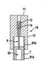
图6和7到9示出了按本发明的刺入单元的两种变型方案,所述刺入单元适合于手动使用,但也可以用作一个刺入系统的组成部分。在此,所述刺入深度基准元件10沿刺入方向(相当于刺针的方向)相对于刺针元件8的纵向位置即使在没有刺入仪器的情况下也可以加以改变,并且存在特定的器件,通过所述器件将所述刺针元件6固定在所设置的位置中。FIGS. 6 and 7 to 9 show two variants of the piercing unit according to the invention, which are suitable for manual use but can also be used as components of a piercing system. In this case, the longitudinal position of the penetration
在图6所示的实施方式中,所述刺针元件6的本体件7以及基准元件本体12具有对应的螺纹,如此构造和布置所述螺纹,使得其相对纵向位置以及由此所述刺血针尖端13相对于所述皮肤接触面11的相对纵向位置可以通过相对扭转来改变。为了将针尖13从所示出的静止位置在一个消毒保护罩14的内部置于一个使用位置中,在该使用位置中所述针尖13相对于所述皮肤接触面11突出,借助于一个啮合在所述本体件7的合适的卡紧轮廓62中的工具来旋转所述刺针元件6的本体件7。这可以手动进行。优选图6所示的刺入单元与刺入仪器结合使用,其中所述刺入深度的调节在这种情况下也可以用手动方式在装入所述刺入仪器之前或者在刺入仪器内部进行。In the embodiment shown in FIG. 6 , the
在图7所示的变型方案中,在所述刺针元件6的本体件7的后面的端部上设置了一个支撑轮廓63,该支撑轮廓63与刺入单元固定座65的相应的多级支撑轮廓64共同作用。在图8和9中可以看出所述支撑轮廓的可能的横截面结构,也就是构造为扇形。In the variant shown in FIG. 7 , a
所述刺入深度基准元件10在这种情况下由一个外罩66构成,该外罩66包围着所述刺针元件的本体件7的前面部分。所述外罩66摩擦连接地固定在所述本体件7上。在初始状态中,所述在图7中分开画出的装入辅助件30处于刺针8的上方。所述装入辅助件30保护着针尖13并且用于将所述刺入单元1在一个旋转位置中装入所述刺入单元固定座65中,所述刺入单元固定座65与所期望的刺入深度相应。在装入时,如果该外罩66的下棱边67接触到所述刺入单元固定座65的上棱边68,那就使所述外罩66相对于所述刺针8向前移动。由此调节所述针尖13相对于所述皮肤接触面11的伸出长度。在装入之后旋下所述装入辅助件30,从而露出所述刺针8以供使用。The penetration
可以实现按本发明的刺入单元的大量其它的变型方案,这些方案也可以在没有刺入仪器的情况下加以使用。在此通常优选所述基准元件本体从皮肤接触面向后延伸并且至少如此程度地包围着所述刺针元件的本体件,使得所述刺针元件相对于所述刺入深度基准元件的纵向位置通过在基准元件本体和刺针元件的本体件之间的接触得到固定。这种接触至少应该为摩擦连接接触(如在图7中一样)。所述刺针元件在基准元件本体内部的摩擦连接的固定(如在图6中一样)对有些使用目的来说特别有利。Numerous other variants of the piercing unit according to the invention are possible, which can also be used without a piercing device. It is generally preferred here that the reference element body extends rearwardly from the skin contact surface and surrounds the body part of the lancet element at least to such an extent that the longitudinal position of the lancet element relative to the penetration depth reference element is defined by the reference element. The contact between the element body and the body part of the lancet element is secured. This contact should at least be a frictional engagement contact (as in FIG. 7 ). A frictionally engaged fixation of the lancet element inside the reference element body (as in FIG. 6 ) is particularly advantageous for some purposes of use.
图10到13示出了一种刺入单元,该刺入单元与此前示出的刺入单元的不同之处首先在于,所述刺针元件6的刺针8具有一条毛细通道70,体液可以通过该毛细通道70的内腔流入所述刺针元件6的试样接纳区域71中。所述刺针元件6由此是一种开头所述类型的微型取样器。在所述试样接纳区域71中(在刺针元件6的本体件7的内部)布置了分析元件。10 to 13 show a piercing unit which differs from the previously shown piercing unit firstly in that the piercing
在这种实施方式中,所述刺入深度的调节同样建立在以下基础上,即所述针尖13离刺入深度基准元件10的皮肤接触面11的间距d借助于定位件16a、17a进行调节,所述定位件16a、17a是刺针元件接合器16和基准元件接合器17的组成部分。In this embodiment, the adjustment of the penetration depth is likewise based on the fact that the distance d of the
所述刺针元件定位件16a在这种情况下构造为双臂的卡夹73,所述卡夹73的朝里的支臂是有弹性的并且具有凸起74,所述凸起74在刺针元件接合器16闭合时啮合在所述刺针元件6的本体件7的相应的空隙75中。在所述刺针元件接合器16的闭合状态中,所述刺针元件定位件16a的纵向位置通过两个止挡16b、6b的共同作用来确定,所述止挡在所示出的情况中一方面由所述卡夹73的内部的限制面所构成,并且另一方面由所述刺针元件本体7的后面的端面所构成。这种刺针元件接合器也在两个方向上起作用,因而所述定位件16a在刺入运动的两个运动方向上与所述刺针元件6相耦合。The
所述刺入深度基准元件10的基准元件本体12主要包括一个敞开的框架77以及横向于纵向方向延伸的、将所述刺针元件6包围的成型件78,其中在所述框架77的下侧面上构造了皮肤接触面11。所述皮肤接触面包围着一个用于所述刺针元件6的刺针8的开口69。The
该实施例表明,所述基准元件本体不一定是封闭的部件。更确切地说一种敞开的结构是合适的,只要其满足在本发明的框架内所要求的功能。尤其以下功能属于所必需的功能,即所述刺针元件6如此与所述基准元件10相连接,使得两个部件可以在纵向方向上进行相对运动以调节所述刺针伸出长度d。此外,在所述刺针元件6和基准元件7之间的连接在纵向方向上产生良好的导向,从而防止两个部件在不同于刺入方向的空间方向上运动。This example shows that the reference element body does not have to be a closed part. Rather, an open structure is suitable as long as it fulfills the required function within the framework of the invention. In particular, the function required is that the
所述基准元件接合器17的具有止挡17b的定位件17a构造在一个在轴向上导引的但不可旋转的支承件80上。一个对应的止挡10b由所述框架77的后面的端面构成。在这种情况下,该止挡10b是一个在单一方向上起作用的接合器,也就是说所述止挡17b、10b的共同作用只是在所述刺入运动的推进阶段中(在图10和11中向下)而不是在回程阶段中确定所述刺入深度基准元件10的相对的纵向位置。The
与在图1到4中相类似,所述刺血针驱动装置4通过一根连接杆19与所述由接合器16、17构成的刺入单元-支架27相连接,其中可通过以下方法来调节所述定位件16、17的相对的纵向位置,即所述连接杆19(所述基准元件定位件16a固定在该连接杆19上)通过围绕着其自身的轴线的旋转可在所述基准元件定位件17a(这里是支承件80)的内部移动。Similar to FIGS. 1 to 4 , the
所述卡夹73可转动地支承在所述连接杆19的端部上并且如此在所述刺入仪器中导引,使得其不依赖于所述连接杆19的旋转位置留在图10所示的卡紧位置中。在所述卡夹73的凸起74的区域中以及在所述相应的空隙75的区域中可以设置电接点,借助于所述电接点可以对处于试样接纳区域中的试样液体进行电测量,如果所述刺入单元6构造为电化学的微型取样器。作为替代方案,可以在所述试样接纳区域71内部设置一个窗口79,以便在使用以光度测量分析进行工作的微型取样器的情况下能够进行必需的光度测量。因为这些测量原理已经公开,所以没有必要进行更详细地解释。The
图14示出一个微型取样器-刺入单元的四个使用阶段(a)到(d),该微型取样器-刺入单元的结构特征与图10到13相应:Fig. 14 shows four use stages (a) to (d) of a micro-sampler-piercing unit, the structural features of this micro-sampler-piercing unit are corresponding to Fig. 10 to 13:
-分图(a)示出了供货状态,在该供货状态中所述刺针元件6摩擦连接地固定在一个确定的相对于所述基准元件10的纵向位置中。这种固定通过在所述基准元件10上的榫舌82来实现,所述榫舌82朝所述刺针元件6的本体件7的限制面压紧。Part (a) shows the delivery state, in which the
-分图(b)示出了对于以一个较小的刺针伸出长度d也就是以较小的刺入深度进行刺入的情况来说在所述刺入运动的换向点上的状态。在从状态(a)移到所述状态(b)中时,所述刺针元件接合器16(图10和11)首先闭合并且所述刺针元件6向下挤压,其中所述止挡16b、6b彼此紧贴。在所述推进阶段中的后面一个时刻,在所述止挡10b、17b之间进行接触,从而所述基准元件10也朝皮肤方向移动。这种运动过程是以下情况的代表事例,即不一定在刺入运动开始之前来调节刺入深度,而是在刺入运动的推进阶段中也可以来调节刺入深度。如果所述皮肤接触面11抵靠在皮肤上,那么所述刺针8就刺入皮肤中并且刺入运动的推进阶段结束。Sub-figure (b) shows the situation at the point of reversal of the piercing movement for piercing with a small needle extension d, ie with a small piercing depth. When moving from state (a) to state (b), the lancet element adapter 16 ( FIGS. 10 and 11 ) is first closed and the
-分图(c)同样示出了在刺入运动的换向点上的使用状态,但是在最大刺针伸出长度d时也就是最大刺入深度时的使用状态。Sub-figure (c) likewise shows the state of use at the reversal point of the piercing movement, but at the maximum needle extension d, ie at the maximum piercing depth.
-如果足够量的试样流入所述刺针元件6的试样接纳区域71中,那就启动所述刺入运动的回程阶段并且刺针元件被拉回到基准元件的内部。在此所述基准元件用在附图中未示出的器件加以固定。所述刺针元件6到达在分图(d)中示出的位置,在该位置中所述刺针8为防止伤害风险拉回到所述皮肤接触面11的后面。在这个位置中,所述刺针元件6的本体件7处于所述闭锁凸起83的后面,如此构造所述闭锁凸起83,使得所述刺针元件6不再可以移回到所述使用位置中(图b或者说c)。通过所述可以设置在基准元件本体12和/或刺针元件6上的闭锁件,在使用所述刺入单元1之后如此限制所述刺针元件6相对于基准元件10的运动,从而可靠地防止再次使用使用过的刺入单元1。- If a sufficient amount of sample has flowed into the
在微型取样器上(图10到14),所述刺入运动的过程有别于刺血针的典型的刺入运动(图1到9)。在使用刺血针的情况下在紧接在到达换向点之后进行刺入运动的回程阶段并且刺入运动也应该在总体上尽快进行,而在使用微型取样器的情况下,所述刺入单元的运动在到达换向点之后的回程阶段中在对于吸入体液来说所必需的时间间隔中中断或放慢。在图15中示出了相应的行程-时间-图。可以看出陡峭的上升曲线,该上升曲线与在推进阶段V中沿刺入方向的迅速移动相应。在所示出的优选的实施方式中,在到达相当于所述刺入运动的换向点的最大值M之后,接下来首先是短促而快速的回程运动R1,所述回程运动R1而后逐渐变为缓慢的回程运动R2。所述回程阶段的用R1表示的区段用于在皮肤组织的内部在针尖前面的区域中形成一个小的空腔,在该空腔中积聚试样液体。在随后的区段R2中,血液通过微型取样器的毛细通道流入该微型取样器的试样接纳区域中。在这个过程结束时,接下来是回程阶段的区段R3,在该区段R3中刺针从皮肤组织中拔出。On the microsampler ( FIGS. 10 to 14 ), the course of the piercing movement differs from the typical piercing movement of a lancet ( FIGS. 1 to 9 ). In the case of a lancet, the return phase of the piercing movement is carried out immediately after reaching the reversal point and the piercing movement should also be carried out as soon as possible overall, while in the case of a microsampler the piercing The movement of the unit is interrupted or slowed down during the return phase after reaching the reversal point for the time interval necessary for the intake of body fluid. The corresponding travel-time diagram is shown in FIG. 15 . A steep rise can be seen, which corresponds to the rapid movement in the thrusting direction during the advancing phase V. In the preferred embodiment shown, after reaching the maximum value M corresponding to the reversal point of the piercing movement, initially a short and rapid return movement R1 follows, which then gradually changes to Move R2 for the slow return stroke. The portion of the retraction phase denoted by R1 serves to form a small cavity in the interior of the skin tissue in the region in front of the needle tip, in which cavity the sample fluid accumulates. In the following section R2, the blood flows through the capillary channels of the microsampler into the sample-receiving region of the microsampler. At the end of this procedure, a section R3 of the return phase follows, in which the lancet is pulled out of the skin tissue.
一种所述的适合于微型取样器的运动过程可以用不同的方式和方法来实现。尤其机械式的弹簧驱动装置适合于所述推进阶段V和所述回程阶段的第一区段R1,而在所述区段R2和R3中比较缓慢的和受控制的运动则优选用电机来驱动。A described movement sequence suitable for a microsampler can be realized in various ways. In particular mechanical spring drives are suitable for the advance phase V and the first section R1 of the retraction phase, while the slower and controlled movements in the sections R2 and R3 are preferably driven by electric motors .
图16和17则应该表明,本发明也可应用在刺入系统中,在所述刺入系统中大量刺入单元并合在一个料盒中并且在刺入仪器内部先后输送到刺入位置中。在图16中示出了适用于此的、从美国专利6,616,616中公开的结构。在该专利中,刺血针形状的刺入单元1处于由塑料制成的盒装带85中,所述刺入单元1如此保持在该盒装带85中,使得其可以轴向移动并且得到导引。在刺入单元1的后面的端部上,刺入单元1具有一个接合器增力气缸86。该接合器增力气缸86用于使处于刺入位置87中的刺血针与耦合机构3相耦合,该耦合机构3则构成了与未示出的刺入驱动装置进行连接的连接件。Figures 16 and 17 should then show that the invention can also be used in piercing systems in which a large number of piercing units are combined in a magazine and are conveyed successively into piercing positions inside the piercing device . The structure disclosed in US Pat. No. 6,616,616 suitable for this is shown in FIG. 16 . In this patent, the lancet-shaped piercing
图17示出了一些变化方案,这些变化方案适合用于在具有盒装的刺入单元的刺入系统上实现本发明。借助于连接杆19来传递由未示出的刺入驱动装置产生的刺入运动,该连接杆19相对于所述盒装带85执行刺入运动24。所述接合器增力气缸86在该实施方式中形成所述刺针元件6的本体件7。所述连接杆19作用于支承件88,调节螺栓89旋入该支承件88中。所述支承件88以及具有皮肤接触面11的刺入深度基准元件10借助于导杆90、91在刺入运动的方向上导引。Figure 17 shows some variants which are suitable for implementing the invention on a piercing system with a boxed piercing unit. The piercing movement produced by a piercing drive (not shown) is transmitted by means of a connecting
在这种结构上,所述基准元件接合器16的定位件16a由所述支承件88构成。存在于所述支承件88中的接纳着所述接合器增力气缸的空隙92的后面的底面形成一个止挡16b,所述止挡16b与一个对应的止挡6b共同作用,该止挡6b在这种情况下由所述刺针元件6的刺针8的后面的端部形成。In this structure, the positioning
所述基准元件接合器17在这种实施方式中单向起作用。其定位件17a由所述调节螺栓89构成,该调节螺栓89的前面的端面作为所述基准元件接合器的止挡17b起作用,所述止挡17b则与所述基准元件10的对应的止挡10b共同作用。The
如果在刺入运动的推进阶段中所述连接杆19向前(在图17中向上)推动,那么所述刺针元件6就首先沿刺入方向移动,直到针尖13从所述将皮肤接触面11包围的开口69中伸出来。在这过程中产生的伸出距离由所述调节螺栓89也就是所述构造在该调节螺栓89上的止挡17b相对于所述基准元件的止挡10b的纵向位置来确定。在这两个止挡接触时,所述基准元件克服复位弹簧93的弹力与所述刺针元件6同步引动,直到进行刺入,而刺入深度则由所述针尖13相对于皮肤接触面11的伸出长度来确定。If the connecting
所述部件88、89和10在这种设计方案中是一个料盒的组成部分,但这些组成部分在每个料盒上仅存在一次。作为替代方案,它们也可以作为刺入仪器的组成部分来实现。无论如何,优选在按本发明的具有盒装的刺入单元的刺入系统上为所述料盒的所有刺入单元仅仅设置一个(共同的)刺入深度基准元件。在此在所述刺入过程之间进行输送运动,借助于输送运动相应地将一个新的刺针元件6置于(在图17中示出的)位置中,在该位置中所述刺入深度基准元件至少在刺入运动的一段中与所述刺针元件一同移动,用于保证所期望的刺入深度。The
本发明可以结合不同的料盒结构加以使用。尤其筒式料盒也属于这样的料盒结构,就象比如在所提到的US 2004/0260325中所说明的一样。The invention can be used in conjunction with different cartridge configurations. In particular, cartridge-type magazines also belong to such a magazine structure, as for example explained in the mentioned US 2004/0260325.
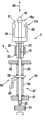
在图18和19所示的刺入系统中,所述刺入单元1的结构及其与所述刺入驱动装置4的连接在很大程度上与图1和2相一致。所述刺入单元1包括一个刺针元件6以及一个刺入深度基准元件10,其中所述刺针元件6具有一根刺针8和一个将该刺针包围的、由塑料制成的刺针元件本体7,并且所述刺入深度基准元件10具有一个在这种情况下为套筒状的基准元件本体12以及一个皮肤接触面11。In the piercing system shown in FIGS. 18 and 19 , the structure of the piercing
借助于一个耦合机构3来建立与所述刺血针驱动装置4的连接,所述耦合机构3包括一个刺针元件接合器16以及一个基准元件接合器17。与图1和2相一致的是,所述刺针元件接合器16的定位件16a由连接杆19的头部18所构成,该头部18啮合在所述刺针元件本体7的相应的固定座31中。所述基准元件接合器在这种情况下也借助于一个包括止动钩25及止动轮廓26的止动接合器来构成,所述止动接合器构造在所述刺入深度基准元件10上或者说一个基准元件支架100上,所述基准元件支架100按照可在纵向方向上移动的方式在所述连接杆19上导引。The connection to the
图18和19所示的刺入系统(就这一点而言与图4相一致)有一个所谓的“弹道式的”刺入驱动装置4,在该刺入驱动装置4上所述刺入运动没有按上述精神得到强制引动。在弹道式的刺入驱动装置上,所述刺入运动至少在换向点的周围、优选在整个运动行程上仅仅由一根或多根驱动弹簧的加速力、由所述驱动弹簧加速的部件的惯性以及对这种运动进行控制或限制的止挡(当然也由在运动的部件之间的摩擦)所确定。The piercing system shown in Figures 18 and 19 (consistent with Figure 4 in this regard) has a so-called "ballistic" piercing
在所示出的情况中,在附图中以压缩状态示出的螺旋弹簧用作驱动弹簧54。该驱动弹簧54与连接杆19相耦合,而一旦触发触发元件59,所述连接杆19就由驱动弹簧54沿刺入方向进行加速。在所示出的实施方式中,所述触发元件59是一个定位器123,该定位器123在所示出的保持位置中锁住所述连接杆19。为触发刺入运动,如此回拉所述定位器123,使得所述连接杆19可以由驱动弹簧54进行加速。In the case shown, a helical spring, which is shown in the compressed state in the drawing, is used as
在装入所述刺入单元1时所述基准元件接合器17闭合。所述刺针元件接合器16则相反只有在触发所述触发元件之后在所述连接杆19向前移动时才闭合。从这个时刻起不仅刺针元件6的运动而且刺入深度基准元件10的运动都精确地跟随着相应的定位件16a、17a也就是连接杆19或者说基准元件支架100的运动。The
在进一步的推进阶段中,所述连接杆19向前移动,直至其以一个止挡面101接触到调节装置126的相应的止挡面125,该止挡面125构造在所述基准元件支架100的后面的端部上。所述止挡面125处于调节螺栓127的螺栓头上,而该调节螺栓127则旋紧在沿刺入方向延伸的螺纹128上。通过所述调节螺栓127的旋转,可以调节所述止挡面125相对于所述基准元件10(以及由此相对于皮肤接触面11)的纵向位置。In a further advancing phase, the connecting
在所示出的优选的实施方式中,由此所述刺入驱动装置4直接仅仅与所述刺针元件6相耦合,而所述基准元件10则通过在刺入运动的推进阶段中起作用的同步装置与所述刺针元件6相耦合并且由此间接地与所述刺入驱动装置4相耦合。所述在总体上用103表示的同步装置的组成部分是两个止挡101和125,这两个止挡在进一步的推进阶段中直至到达刺入运动的换向点之前彼此如此抵靠,使得其相对的间距确定所述针尖13相对于所述刺入深度基准元件10的接触面11的纵向位置并且由此确定所述刺入深度。所述止挡101、125因此称为刺入深度限制止挡。In the preferred embodiment shown, the piercing
在到达换向点时,所述驱动弹簧54拉长,从而再度拉回所述连接杆19,并且由此开始刺入运动的回程阶段。在所示出的情况下,所述驱动弹簧54的弹力因此不仅在刺入运动的推进阶段中而且在其回程阶段中都用于所述刺入单元的加速。When the reversing point is reached, the
对于所示出的刺入系统的优选功能来说,有一点也十分重要,即所述基准元件10在推进阶段的一段中并且尤其优选(象下文还要详细解释的一样)也在回程阶段的一段中借助于一个基准基础件146静置于一个基准元件支承结构105上。在此基准基础件是指一个功能件,该功能件直接或间接地与所述基准元件10相连接,并且该功能件的向后的运动行程在与所述基准元件支承结构共同作用下限制在一个指定的位置中。在所示出的结构中,该功能件由一个凸肩构成,该凸肩构造在一个刺针元件复位闭锁装置138上,所述刺针元件复位闭锁装置138与所述基准元件支架100相连接并且其功能在下文中还要更详细解释。For the preferred function of the piercing system shown, it is also very important that the
在这里所示出的实施方式中,在考虑到其余部件的尺寸的情况下如此选择所述基准元件支承结构105的位置,从而只有在快要到达刺入运动的换向点前基准元件止挡101、125才接触,从而所述基准元件支架100在到达换向点之前仅仅稍微从所述基准元件支承结构105上抬起。即使所述基准元件10可以自由地沿刺入方向移动(也就是说尤其不碰撞到处于其运动行程上的本体件),所述在图21B中示出的最大升程dh最高为5毫米,优选最高为3.5毫米并且尤其优选最高为2毫米,所述基准基础件146从所述基准元件支承结构105上抬起该最大升程dh。In the embodiment shown here, taking into account the dimensions of the remaining components, the position of the
在所述回程阶段开始时,所述基准元件10与刺针元件6一起向后移动了短的距离dh,所述基准基础件146从基准元件支承结构105上抬起该距离dh。这种反向运动一方面由皮肤表面的弹性另一方面由所述连接杆19及刺针元件6的反向运动所引起,所述皮肤接触面11就抵靠在所述皮肤表面上,其中在这些元件及刺入深度基准元件10或者说基准元件支架100之间的摩擦引起足够的力传递。At the start of the retraction phase, the
通过所述基准元件支承结构105来停止所述基准元件支架100的进一步的反向运动并且由此停止所述基准元件10的进一步的反向运动,而所述连接杆19以及由此所述刺针元件6通过弹簧54的力继续向后拉,直到所述运动通过所提到的刺针元件复位闭锁装置138的闭锁元件137停止下来。在所示出的情况中,所述刺针元件复位闭锁装置138包括一个弹簧臂形式的弹簧元件139,该弹簧臂在其自由的端部上支撑着构造为止动爪的闭锁元件137。该止动爪有一个斜切的滑动面140,在刺入运动的推进阶段中一个相应的滑动面141从所述滑动面140旁边滑过,所述滑动面141构造在一个布置在所述连接杆19上的止动凸起142上。在这种滑动过程中,所述刺针元件复位闭锁装置137的弹簧臂139有弹性地朝侧面变形。一旦所述止动凸起142经过所述闭锁元件137,那么该闭锁元件137就由于由弹簧臂139施加的弹力再度返回到其原始的位置中,在所述原始的位置中该闭锁元件137使所述连接杆19以及由此所述刺针元件6停止下来,其中所述连接杆19的止动凸起142的止挡面143顶靠在所述闭锁元件137的止挡面144上。Further reverse movement of the
所述刺针元件复位闭锁装置138也可以构造为其它结构。通常在原则上每种元件都合适,通过该元件所述刺入单元6的复位运动可以在一个指定的纵向位置中停止。优选如此相对于所述皮肤接触面11的通过基准元件支承结构105预先给定的纵向位置来选择这个纵向位置,使得所述刺针元件8的尖端13相对于所述皮肤接触面11的平面突出指定的剩余刺入深度。The needle element
图18和19表明,使用完全不同类型的接合器来作为在刺入驱动装置4和刺入单元1之间的耦合机构的组成部分。所述刺针元件接合器18在刺入运动的推进阶段中使所述刺入驱动装置4与刺针元件6相耦合,并且而后在这些元件之间形成双向起作用的固定的连接。在所述刺入驱动装置4和基准元件6之间的连接间接地通过基准元件支架100来建立。这个基准元件支架100一方面在装入所述刺入单元1时借助于双向起作用的基准元件接合器17固定地与所述基准元件10相连接。另一方面所述基准元件支架100是所述同步装置103的组成部分,而该同步装置103则包括两对止挡125、101和143、144,这两对止挡分别形成一个朝一个方向起作用的(单向的)接合器,如此构造所述接合器,使得所述连接杆19以及与该连接杆19一起所述刺针元件6可通过在所述止挡125和144之间的距离Δd相对于所述基准元件进行移动。就象下文还要详细解释的一样,Δd优选形成在最大的刺入深度dm和剩余刺入深度dr之间的差值。FIGS. 18 and 19 show that completely different types of adapters are used as components of the coupling mechanism between the piercing
通过图18和19的结构,可以实现在图20中以行程-时间-图(“刺入模式”)的形式示出的刺入运动,所述刺入运动首先适合于微型取样器-刺入系统,普遍适用于一些刺入系统,这些刺入系统的刺针元件具有用于接纳试样的毛细通道。图21示出了一个在很大程度上与图18和19所示刺入系统相一致的刺入系统的四个使用位置,其中几个对这里所解释的功能来说无足轻重的结构元件得到简化。相当于使用位置A到D的时刻在图20中用这些字母来标出。Through the structure of Figures 18 and 19, the piercing movement shown in the form of the stroke-time-diagram ("piercing mode") in Fig. systems, are generally applicable to piercing systems whose lancet elements have capillary channels for receiving the sample. Figure 21 shows four positions of use of a piercing system that largely corresponds to the piercing system shown in Figures 18 and 19, in which several structural elements that are insignificant to the function explained here are simplified . The times corresponding to the use of positions A to D are marked with these letters in FIG. 20 .
在图20中示出了在推进阶段V及回程阶段R中刺针元件的刺入深度d的时间变化曲线,其中所述回程阶段R包括第一回程区段R1、收集区段S以及第二回程区段R2。时间轴划分不均匀。所述运动的用T1表示的区段在实践中在几毫秒内就已过去,而用T2表示的运动区段(在收集区段之前的制动)则持续数百毫秒并且所述收集区段(T3)则持续几秒钟的时间。FIG. 20 shows the temporal profile of the penetration depth d of the lancing element in the advance phase V and in the return phase R, wherein the return phase R comprises a first return segment R1, a collection segment S and a second return segment. Section R2. The time axis is not evenly divided. The segment of motion denotedT1 passes in practice within a few milliseconds, while the segment of motion denotedT2 (braking before the collection segment) lasts hundreds of milliseconds and the collection The segment (T3 ) lasts for several seconds.
在所述推进阶段V结束时(使用位置B),所述刺入元件达到一个最大的刺入深度dm,所述最大的刺入深度dm按刺入仪器的调节情况在典型情况下为0.8毫米到2.3毫米。随后进行第一回程区段R1,在该第一回程区段R1中所述刺入元件部分拉回了一个回程距离Δd并且在末端制动,使得所述刺入元件以一个预先给定的比如0.5毫米的剩余刺入深度dr伸入皮肤中(使用位置C)。最后跟随的是一个第二回程区段R2(使用位置D),在该第二回程区段R2中所述刺针元件6的刺针8完全从皮肤中拔出。At the end of the advancing phase V (use position B), the piercing element reaches a maximum piercing depth dm, which is typically 0.8 mm according to the setting of the piercing device to 2.3 mm. This is followed by a first retraction section R1 in which the piercing element is partially retracted by a retraction distance Δd and is braked at the end, so that the piercing element travels at a predetermined speed, for example A remaining penetration depth dr of 0.5 mm penetrates into the skin (use position C). Finally, a second retraction section R2 (use position D) follows, in which the lancing
在图19、20和21所示的结构上,所述第二回程区段在收集阶段结束时通过以下方法来启动,即所述闭锁定位器145从在图19和21A到21C中所示出的啮合位置中拉到一个在图21D中示出的回程位置中,使得所述复位闭锁装置138与所述连接杆19一起被所述驱动弹簧54向后移动。由此结束所述回程阶段并且所述刺针元件6的刺针8完全从皮肤中移出。On the construction shown in Figures 19, 20 and 21, the second return segment is activated at the end of the collection phase by the
比较一下在图15和20中示出的刺入模式,第一个区别在于,即所述剩余刺入深度dr在回程阶段的收集区段S中实际上没有变化,而是在图18到21中示出的结构中通过所述基准元件支承结构105和刺针元件复位闭锁装置138的共同作用预先规定为恒定不变。但尤其重要的是,所述最大刺入深度dm可以不依赖于剩余刺入深度dr进行调节。就这一点而言,图18到21所示刺入系统不同于此前所说明的刺入系统,在此前所说明的刺入系统上刺入深度的调节影响到整个刺入运动,并且因此在调节最大的刺入深度dm时就不可避免地改变剩余刺入深度dr,在该剩余刺入深度下试样被接纳到微型取样器中。Comparing the piercing patterns shown in FIGS. 15 and 20 , the first difference is that the remaining piercing depth dr practically does not change in the collection section S of the return phase, but in FIGS. 18 to 21 In the configuration shown in , the interaction of the
在本发明的框架内已经发现,对试样提取的质量以及对在使用微型取样器-刺入系统时的疼痛感受来说有十分有利的是在这里称为剩余刺入深度的刺入深度不依赖于所调节的最大刺入深度近似地保持恒定,其中所述刺针元件的刺针在试样收集过程中以所述称为剩余刺入深度的刺入深度伸入皮肤中。尽管如此在接纳试样的过程中所述剩余刺入深度的微小的波动或者所述刺针元件的缓慢移动是可以接受。但是要求在接纳试样的过程中所述最大的刺入深度dm可以不依赖于所述剩余刺入深度的在时间上的平均值(Mittel)进行调节。It has been found within the framework of the present invention that it is very advantageous for the quality of the sample extraction and for the pain perception when using the microsampler-piercing system that the puncture depth, referred to here as the remaining puncture depth, be different. Depending on the set maximum puncture depth, the lancets of the lancet element penetrate into the skin at the puncture depth referred to as the remaining puncture depth during sample collection, which remains approximately constant. Nevertheless, slight fluctuations in the remaining penetration depth or slow movements of the lancet element during sample admission are acceptable. However, it is required that the maximum puncture depth dm can be adjusted independently of the time-average (Mittel) of the remaining puncture depths during the admission of the sample.
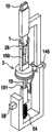
利用刺入系统的另一种实施例可以实现具有借助于图20所解释的特点的刺入模式,在图22中示出该实施例的侧视图,在图23中示出其横截面并且在图24中示出其透视倾斜图。Another embodiment of the piercing system can be used to achieve a piercing mode with the characteristics explained by means of FIG. 20, which is shown in side view in FIG. A perspective oblique view thereof is shown in FIG. 24 .
所述刺入单元1及接合器16和17的结构与图18和19相一致。这些元件在这里也用相同的附图标记来表示,因而在此不再对其功能进行赘述。The structures of the piercing
与此相反,所述刺入驱动装置4大大有别于图18和19。该刺入驱动装置4是具有升程补偿机构的转子驱动装置,以下还要对其进行详细解释。In contrast, the piercing
以下部件属于所示出的刺入仪器2的刺入驱动装置4,即驱动弹簧201、用于张紧驱动弹簧的张紧转子202以及由所述驱动弹簧201驱动的驱动转子203。所述驱动转子203的旋转运动借助于曲线控制机构形式的控制装置转换为所述刺针元件6的刺入运动。刺针元件-控制曲线205构造为在所述驱动转子203中的凹槽,并且被一个(啮合在控制曲线205中的栓的形式的)刺针元件-控制曲线游标206经过(abfahren),该刺针元件-控制曲线游标206与连接杆19相连接,而所述刺针元件6则与所述连接杆19相耦合。The following components belong to the piercing
所述刺入深度基准元件10的运动同样通过曲线控制机构来控制,所述曲线控制机构包括基准-控制曲线212以及基准-控制曲线游标213。所述基准-控制曲线212同样构造为在所述驱动转子203中的凹槽。与所述基准元件支架100相连接的控制曲线游标213啮合在所述控制曲线212中。The movement of the penetration
为调节刺入深度,所述两条控制曲线205和212之间的间距可借助于可调节的轴向支承结构形式的调节装置214进行调节。所述两条控制曲线205和212布置在所述驱动转子203的第一部分203a上或者说所述驱动转子203的第二部分203b上。借助于所述调节装置214,可以改变在所述驱动转子203的第一部分203a及其第二部分203b之间的间距。To adjust the penetration depth, the distance between the two
在使用时,所述刺入仪器以一个仅仅在图21中示意示出的、将外壳开口35包围的外壳皮肤接触面33朝使用者的皮肤表面挤压。随后,为了(主动的)升程补偿,确定所述基准元件10与皮肤表面之间的间距。为此,借助于电机220使可沿刺入方向移动的第一滑块221移向所述皮肤表面。所述驱动装置4包括所述由连接杆19构成的刺针元件-定位件16a以及所述由基准元件支架100构成的基准元件定位件17a支承在所述第一滑块221上。所述滑块221向前移动,直到所述基准元件10接触到皮肤。这一点可通过电子方式比如通过感应测量或电容测量予以确定。随后,所述滑块221再度稍许回移,直到产生一个指定的到皮肤表面的间距。During use, the piercing device is pressed against the skin surface of the user with a housing
在触发刺入运动之后,所述刺针元件-定位件16a及基准元件-定位件17a在刺入运动的推进阶段中通过所述相应的控制曲线205、212的上升的侧面向前移动。在所述刺针元件6的刺针8刺入皮肤表面中的过程中,所述基准元件10以其皮肤接触面11抵靠在所述皮肤表面上,从而为精确的刺入深度确定了基准点。After triggering the piercing movement, the needle
为补偿Z-变化,在这种设计方案中也设置了一个升程补偿机构38,其中这里甚至组合使用两个升程补偿机构:In order to compensate for the Z variation, a
-一方面通过以下方法实现主动的升程补偿机构,即在触发刺入运动之前探测所述皮肤表面的位置并且使随后的刺入运动与事先探测到的位置(这里通过整个升程距离的移动)相匹配。这种主动的升程补偿的形式不仅在所示出的设计方案中而且在其它的结构实施方案中都十分有利。On the one hand, an active lift compensation mechanism is realized by detecting the position of the skin surface before triggering the piercing movement and aligning the subsequent piercing movement with the previously detected position (here by moving the entire lift distance ) match. This form of active lift compensation is very advantageous not only in the configuration shown but also in other structural embodiments.
-此外设置了一个被动的升程补偿机构,在此通过以下方法来实现该升程补偿机构,即所述第一滑块221按照可沿纵向方向移动的方式支承在第二滑块222上,该第二滑块222可以克服压紧控制弹簧223的力往回推移。由此确定最大的压紧力,该压紧力通过所述基准元件10作用于皮肤表面上。这种附加的被动升程补偿机构是可任意选择的。- Furthermore, a passive lift compensation mechanism is provided, which is realized here by the fact that the
在到达刺入运动的换向点之后,所述刺针元件-定位件16a及基准元件-定位件17a往回拉动。所述作用于刺针元件-定位件的曲线控制机构205、206具有这样的特点,即所述刺针元件-控制曲线游标206在复位运动中从其在相应的控制曲线205中啮合状态中松开。这意味着,所述控制曲线游标没有象通常很普遍的一样在整条控制曲线中如此强制引动,因而所述游标的以及由此由该游标控制的元件(刺针元件或基准元件)的沿刺入方向的指定的纵向位置相当于所述控制曲线游标在控制曲线上的每个位置。更确切地说,所述控制曲线游标的以及由此受控制的元件的纵向位置在控制曲线的啮合状态松开时至多在一个空间方向上(沿刺入方向或者反向于刺入方向)受到限制,但至少在相反的空间方向上是自由的。这在所示出的设计方案中通过以下方法来达到,即所述形成控制曲线205的凹槽如此得到加宽,使得所述控制曲线游标206在那里不再受到控制。所述刺针元件-定位件16a(以及由此所述刺针元件)因此在回程阶段中没有主动地被所述刺针元件-控制曲线游标206拉回。After reaching the reversal point of the piercing movement, the needle
取而代之的是,借助于复位弹簧225来引起所述刺针元件-定位件16a的复位运动。该复位弹簧225使所述刺针元件-定位件16a与所述第一滑块221相耦合并且由此也与所述驱动装置4相耦合。在回程阶段中,所述刺针元件-定位件16a因此被所述复位弹簧225相对于所述驱动装置向后移动,直至其与第二控制曲线游标226一起顶压到另一条控制曲线227上,所述控制曲线227设置在驱动转子203的第二部分203b上。所述另一条控制曲线227因此形成一个复位闭锁装置,利用该复位闭锁装置所述刺针元件6的运动在所述第一回程区段R1的末端停止下来。由此产生所述刺针元件-定位件16a相对于所述基准元件-定位件17a的指定的位置,在该位置上所述刺针8的尖端13以一个预先给定的剩余刺入深度突出超过所述刺入深度基准元件10的皮肤接触面11。在所述收集阶段结束后,所述刺针元件6完全从皮肤中拔出来,方法是用电机220移回所述第一滑块221。Instead, a return movement of the lancing
在附图17、18/19和22至24中示出的实施方式示范性地表明,所述刺入深度基准元件10不必(就象比如在图1和2中一样)在整个推进阶段中与所述刺针元件6一起移动。更确切地说可以优选所述刺入深度基准元件10仅仅在所述推进阶段的紧靠在换向点前面的一段中与所述刺针元件一起移动(也就是说同时移动,但不一定以相同的速度移动)。所述刺入深度基准元件10在到达换向点之前与所述刺针元件6一起移动了一个升程,优选该升程(沿刺入方向的路程)最高为5毫米,优选最高为3.5毫米,并且特别优选最高为2毫米。在图17和18/19所示的结构中通过以下方法来实现这一点,即所述刺入深度基准元件10在一个静止位置中静置于一个基准元件支承结构上,并且在所述刺针元件快要到达换向点之前被所述刺针元件的运动从这个静止位置带动。但是如图22到24所示出的一样,也可以设想其它的结构。The embodiments shown in accompanying
此外,优选在很短的时间内经过所述刺入运动的部分区段,在所述刺入运动的部分区段的过程中所述刺入深度基准元件在推进阶段中(也就是说在到达换向点之前)与所述刺针元件一起移动。优选这个持续时间应该最大为100毫秒,优选最大50毫秒并且尤其优选最大为10毫秒。Furthermore, the partial section of the piercing movement during which the piercing depth reference element is in the advancing phase (that is to say after reaching before the reversing point) moves together with the lancet element. Preferably, this duration should be at most 100 milliseconds, preferably at most 50 milliseconds and particularly preferably at most 10 milliseconds.
在本发明的框架内已经发现,通过上述的、可以单个地或以组合方式使用的措施,一方面可以精确地控制刺入深度,另一方面在所述短促的挤压时皮肤的粘弹特性不会导致剩余刺入深度的精确定义因皮肤的变形受到不良影响。作为补充,优选在一种在图20中示出的类型的刺入模式中所述在到达换向点(最大的刺入深度)的时刻和在收集区段的开始之间的第一回程区段R1的持续时间最大为2秒,优选最大为1秒,并且尤其优选最大为0.5秒。Within the framework of the present invention it has been found that by means of the above-mentioned measures, which can be used individually or in combination, on the one hand the penetration depth can be precisely controlled and on the other hand the viscoelastic properties of the skin during said short squeeze The precise definition of the remaining penetration depth is not adversely affected by deformation of the skin. As a supplement, preferably in a piercing pattern of the type shown in FIG. The duration of segment R1 is at most 2 seconds, preferably at most 1 second, and particularly preferably at most 0.5 seconds.
在图25中所示出的刺入系统中,所述刺入单元及接合器16和17的结构基本上与图18/19和22到24相一致。这些元件再度用相同的附图标记来表示并且不再赘述。In the piercing system shown in FIG. 25 , the structures of the piercing unit and
同样与图18和19相一致,所述基准元件定位件17a由一个基准元件支架100所构成,所述基准元件支架100可在未示出的外壳中沿纵向方向移动并且在所述刺入运动的所示出的初始位置中静置于一个基准元件支承结构105上。所述基准元件支架100和通过基准元件接合器17与该基准元件支架100相连接的刺入单元1在外壳件301中在纵向方向上导引。在此未示出其余的外壳。但是就象在图2c和22中示范性地示出的一样,在这个刺入系统上也存在一个外壳-皮肤接触面。Also consistent with FIGS. 18 and 19, the
与图18和19的另一共性在于,使用弹道式的刺入驱动装置4。但是在所示出的情况下该刺入驱动装置按照“锤子-铁砧-原理”进行工作,也就是说一个称为锤子302的在图25中仅仅以符号示出的部件快速朝一个铁砧303的方向移动,该铁砧303本身通过一个耦合机构3与所述刺入单元1处于有效连接之中。Another commonality with FIGS. 18 and 19 is the use of a ballistic piercing
在该实施方式中,所述基准元件接合器17在装入所述刺入单元1时同样闭合。所述基准元件支架100在此形成一个用于固定一次性刺入单元1的支架27。只有在所述与铁砧303相连接的连接杆19向前移动时,所述刺针元件接合器16才闭合。与图18和19的另一种一致性在于,这里也设置了一个同步装置103,该同步装置103包括两个相对应的止挡101和125。在这里,所述刺入驱动装置4同样仅仅直接与所述刺针元件6相耦合,而所述基准元件10则通过所述在刺入运动的推进阶段中起作用的同步装置103与刺针元件6相耦合并且由此间接地与所述刺入驱动装置4相耦合。In this embodiment, the
不同于图18和19的是,在图25中刺入深度调节通过一个与刺针元件6(不是与基准元件10)相连接的刺入深度限制止挡的纵向移动来实现。在所示出的实施方式中,一个刺入深度调节环305可在所述连接杆19的螺纹306上旋转,并且由此可以在其相对于刺针元件6的纵向位置中进行调节。所述刺入深度调节环305用于有弹性地支承一个可在连接杆19上沿纵向方向移动的止挡环307,其中所述有弹性的支承通过由金属制成的压紧弹簧308来实现。In contrast to FIGS. 18 and 19 , in FIG. 25 the penetration depth adjustment takes place by longitudinal movement of a penetration depth limiting stop connected to the needle element 6 (not to the reference element 10 ). In the embodiment shown, a penetration
如果在所述锤子302的影响下所述铁砧303向前(在图25中向左)移动,那么所述双向起作用的刺针元件接合器16就闭合。如果所述止挡面101和125彼此接触,那么它们就形成一个单向起作用的接合器,通过该接合器在所述连接杆19(以及由此在驱动装置4)与基准元件10之间产生有弹性的连接。所述部件的纵向尺寸如此彼此协调,从而在随后的到达接触时刻(所述刺入深度基准元件的皮肤接触面碰到皮肤表面)之前的运动阶段中,在皮肤接触面11和刺针元件6的尖端13之间的间距小于所期望的(预先给定的)刺入深度数值。优选在这个运动阶段中,所述刺针元件6的尖端13甚至沿刺入方向处于所述皮肤接触面的后面,从而只有在接触时刻之后才刺入皮肤中。If the
在接触皮肤时,所述基准元件10停止。所述压紧弹簧308的弹性(一般说来就是在刺入深度基准元件10和刺入驱动装置4之间的接合器的弹性)确保,在刺针元件可以进一步向前移动直到达到刺入运动的换向点之前的过程中,所述皮肤接触面11以一个相当于弹性常数的压力朝皮肤挤压并且将皮肤拉紧。Upon contact with the skin, the
在所示出的实施方式中,通过以下方法实现必要的对刺针元件的运动的限制,即在所述刺入深度调节环306和止挡环307之间的相对运动停止下来,如果在这些元件上设置的止挡309或者说310彼此碰到一起。由此限制和实现所述刺针元件6相对于基准元件10的最大运动行程,使得所述刺针元件6在刺入运动的换向点上沿刺入方向相对于所述刺入深度基准元件10具有一个指定的纵向位置。因此,所述止挡309和310也作为刺入深度限制止挡起作用。所述止挡309和310以及止挡101和125形成两个单向起作用的接合器,并且在所述刺入运动的换向点上如此彼此抵靠,使得其彼此间的相对间距确定所述刺入深度。In the embodiment shown, the necessary limitation of the movement of the lancet element is achieved by stopping the relative movement between the penetration
所述刺入运动的回程阶段由复位弹簧311来驱动,该复位弹簧311一方面支撑在一个固定在外壳上的支承件312上并且另一方面支撑在所述铁砧303上。首先,将所述刺针元件6向后拉,其中所述针尖13拉回到所述皮肤接触面11后面并且所述止动钩25再度进入止动轮廓26中,使得其将所述刺针元件6的纵向位置固定在所述刺入深度基准元件10中。所述连接杆19的进一步的往回运动作用于整个刺入单元1,直至该刺入单元1因所述基准元件支架100与基准元件支承结构105的接触而停止。The return phase of the piercing movement is driven by a
在所示出的最终位置中,所述刺入深度基准元件10通过一对相应的止挡143、144与所述刺入驱动装置4相耦合。在图25中所述同步装置103同样一方面通过所述止挡101、125、309、310并且另一方面通过所述止挡143和144双向起作用。但是与在图18和19中所不同的是,由此并未确保一个指定的剩余刺入深度,而是通过所述在回程阶段中起作用的止挡143、144将所述基准元件支架100并且与该基准元件支架100一起将所述基准元件固定在所示出的位置中。所使用的刺入单元1可以在总体上借助于一个这里未示出的顶出器从所述支架100中压出和顶出。In the end position shown, the penetration
本发明的在图25中示出的实施方式的实际试验表明,由此实现可以良好再现的刺入深度以及极少的疼痛感受。另外根据发明人的目前的知识水平,这一点应该归因于以下情况,即在刺入时所述刺入深度基准元件的皮肤接触面向皮肤表面施加一个足以拉紧皮肤的压力。因此应该如此构造所述刺入驱动装置和耦合机构,从而在接触皮肤的时刻(所述皮肤接触面11与皮肤表面接触的时刻)所述刺针元件8的尖端13相对于所述皮肤接触面没有或者仅仅稍稍突出,从而在针尖进入皮肤的那一刻所述皮肤接触面的压力就已发挥作用。Practical tests of the embodiment of the invention shown in FIG. 25 have shown that a well-reproducible penetration depth and a very low pain perception are thereby achieved. Furthermore, according to the present state of knowledge of the inventors, this is due to the fact that the skin-contacting skin-facing surface of the penetration depth reference element exerts a pressure sufficient to tighten the skin during penetration. The piercing drive and the coupling mechanism should therefore be constructed such that at the moment of contact with the skin (the moment when the
在本发明的框架内已经发现,所述刺针元件8和皮肤接触面11的纵向位置以及由皮肤接触面11(在所述推进阶段的接下来的部分区段中)向皮肤表面施加的压力可以通过试验得到优化,从而由此决定性地减少由刺针元件刺入皮肤中引起的皮肤变形对刺入深度的可再现性的影响。试验表明,这一点是可能的,从而在实际上皮肤变形不再对刺入深度产生干扰性影响。这一点也通过以下情况得到表明,即在皮肤中的实际刺入深度很好地与调节的仪器刺入深度(在尖端13和皮肤接触面11之间的间距)相一致,而在没有采取这里所描述的措施的情况下则发现,在皮肤中的实际刺入深度比在仪器上所调节的刺入深度小0.3毫米以上。It has been found within the framework of the present invention that the longitudinal position of the
在此,皮肤接触面的大小也起一定的作用。皮肤接触面的直径应该至少为1.5毫米,但优选不超过6毫米。所述皮肤接触面11必须尽可能无棱边(英语:soft edged”)。尤其以下情况是不利的,即在将装入辅助件30从刺入深度基准元件10上取下时在皮肤接触面11的区域中产生尖锐的棱边,就象在使用在这方面常用的解裂槽-结构(具有由薄塑料制成的薄弱处)时不可避免的一样。因此,在所示出的情况下,借助于一个由软的高弹性塑料制成的连接型材30a在装入辅助件30和刺入深度基准元件10之间建立连接。但也可以设想其它的结构,只要保证所述皮肤接触面在取走装入辅助件30之后无断裂棱边。优选使用一种皮肤接触面的设计方案,在该设计方案中所述皮肤接触面在刺针元件-出口的周围弯曲成凸起的。The size of the skin contact area also plays a role here. The diameter of the skin contacting surface should be at least 1.5 mm, but preferably not more than 6 mm. The
因为皮肤拉紧的效应以及与此相关的刺入深度的突出的可再现性取决于许多因素,所以无法就与此有关的最佳参数作出具有普遍约束力的说明。但是,所述刺入深度基准元件10的皮肤接触面11在所述推进阶段的最后部分区段中压紧在皮肤表面上的压力应该如此之高,使得与刺针元件在皮肤中的刺入相关的皮肤变形(“凹入”)在实际上对刺入深度的可再现性没有干扰性影响。这个压力应该至少为1N/cm2,优选至少3N/cm2并且尤其优选至少5N/cm2。在本发明的框架内已经发现,由这个较强的压紧力产生的内压在组织中适合于将在刺针刺入皮肤表面中时皮肤的凹入通常具有的负面影响减少到最低限度,从而实现刺入深度的极佳的可再现性。与此同时仅仅产生极少的疼痛感受。Since the effect of skin tightening and thus the outstanding reproducibility of the penetration depth depends on many factors, no generally binding statements can be made regarding the optimum parameters in this regard. However, the pressure with which the
借助于所述同步装置103使刺入深度基准元件10间接地耦合到所述驱动装置4上并且/或者通过所述金属的压紧弹簧308引起弹性耦合及压力控制,应该认为这为所示出的刺入系统的突出的功能作了重要贡献。如此预张紧地安装所述弹簧,使得其在其最大的膨胀状态中传输所期望的最小力。每长度单位的力变化(弹性系数)优选最大为0.1N/mm。The penetration
所述同步装置(尤其有弹性的同步装置)也可以在所述刺入单元的本身内部得以实现,其中可以在可彼此相对移动的元件(刺针元件及刺入深度基准元件)上设置相应的止挡。在使用有弹性的同步装置的情况下,在此可以设置弹簧,该弹簧一方面支撑在所述刺针元件上并且另一方面支撑在所述刺入深度基准元件上。The synchronizing means, in particular elastic synchronizing means, can also be implemented within the piercing unit itself, wherein corresponding stops can be provided on the elements that are movable relative to each other (needle element and penetration depth reference element). block. When a resilient synchronization device is used, a spring can be provided here, which is supported on the one hand on the lancet element and on the other hand on the penetration depth reference element.
在图26到30中示出的刺入系统的突出之处首先在于,借助于刺针元件带331来大量生产这里优选构造为简单的金属的针状刺血针330的刺针元件6(图26)。所述刺针元件带331具有支承薄膜328和将刺血针覆盖并且由此将其卫生封装的覆盖薄膜329,所述刺血针330分别以其后面的(背向尖端13的)端部以粘贴方式固定在所述支承薄膜328上。两层薄膜优选由塑料制成。带状刺血针的大量生产已经普遍公知,比如从德国专利文件28 03 345以及EP 1 360 935 A1中得到公开。The piercing systems shown in FIGS. 26 to 30 are distinguished primarily by the mass production of the lancing
结合本发明重要的是,即所述刺针元件带331的支承薄膜328及覆盖薄膜329都很薄。所述支承薄膜328的厚度优选最高为100微米,尤其优选最高为50微米并且还进一步优选最高为30微米。所述覆盖薄膜329的厚度应该最高为50微米,优选最高为25微米并且还进一步优选最高为15微米。What is essential in connection with the invention is that both the
在本发明的框架内,所述刺针元件带331不仅仅用于以低廉的成本及消毒的方式来包装大量的刺血针并且以简单的方式提供使用。更确切地说,所述在本发明的框架内的支承薄膜328在刺入过程中在皮肤接触面的区域中形成一层卫生层,并且由此是所述刺入深度基准元件的组成部分。在图27到30中示出了刺入系统的一种合适的结构的四个使用位置。Within the scope of the invention, the
所述刺针元件带331步进式地由一个未示出的输送装置进行输送,从而每次一根刺血针330处于基准元件基础件333前面的刺入站332上(图28)。压带器334是一个在总体上用335表示的刺入准备装置的组成部分,通过该刺入准备装置将处于所述刺入站332上的刺针元件6置于刺入位置中,在该刺入位置中该刺针元件6的尖端13露出来并且定位在刺入方向上,而所述支承薄膜328则在针尖13的周围覆盖所述基准元件基础件333(图29)。在所示出的实施方式中,所述压带器334以L形状构造在一个平行于刺入方向的平面中,并且该压带器334如此推到所述刺针元件带331上,使得该刺针元件带331折弯成直角,其中刺针元件带的一部分覆盖所述基准元件基础件333的(在图左边的)前面的棱边并且在那里形成所述皮肤接触面11。这是本发明的一种实施方式的实施例,在该实施方式中不是整个刺入深度基准元件10,而仅仅是上面构造皮肤接触面的元件设置用于一次性使用(用完即丢的)。The
一个从后面(在图中从右往左)移向刺血针的刺血针夹紧器338用于移动相应的刺血针,其中所述刺血针夹紧器338的空隙339包围着刺血针的后面的端部(图30)。在此所述刺血针夹紧器338相对于基准元件基础件333的移动行程受到一个刺入深度调整螺栓340的限制。如果所述刺入深度调整螺栓340的前面的端部止动于所述基准元件基础件333上,那么在刺血针夹紧器338进一步向前(在图中向左)移动时所述基准元件基础件333以及由此所述形成皮肤接触面的支承薄膜328(因此在总体上所述由支承薄膜328和基础件构成的基准元件)与所述刺血针330一起移动,其中所述在图29B中示出的刺针伸出长度d确定了刺入深度。通过向前运动刺入在图30A中示出的手指342。A
在该实施方式的实际试验的框架内已经发现,即使在所述支承薄膜328或覆盖薄膜329的残余部分在所述皮肤接触面11的区域中没有形成光滑的覆盖层,而是比如打起褶皱,在使用很薄的薄膜(具有上文所说明的优选的厚度)时也令人惊讶地产生可以极佳地再现的刺入深度。因此,在本发明的这种实施方式中,其优点可以以理想的方式与刺针元件带的优点相组合。这一点尤其适用,如果所述刺针元件带不仅支承着刺针元件(刺血针),而且也交替地支承着测试元件并且该系统构造为集成的系统,在该系统上不仅提取血液而且也进行分析。组合的分析元件-带能够以简单的方式实现在这样的集成的系统上所必需的输送功能,而与此同时通过作为基准元件的组成部分的支承带的使用而避免在皮肤接触面的区域中出现卫生问题。在此,所述测试元件因其中包含的试剂的敏感性而优选单独制造并且通过粘贴固定在所述支承薄膜328上。In the framework of practical tests of this embodiment, it has been found that even the remainder of the
在图31到33中示出了刺入系统的对功能来说重要的部件,在该刺入系统上所述耦合机构3的结构特别简单并且节省空间位置,通过该耦合机构3将刺针元件6和基准元件10经由连接杆19与未示出的驱动装置相连接。所述刺针元件6在所示出的情况中仅仅包括一根金属针8。所示出的耦合机构的独特之处在于,所述刺入深度基准元件10同时构成一个夹紧器350,该夹紧器350象钳子一样包围着刺针元件6并且由此将其固定。在所示出的情况中,所述夹紧器350的夹紧臂351由一个闭合机构352进行致动,这里不必对其进行详细解释,因为合适的机械原理(比如用于将笔芯夹在活动铅笔中)已经得到公开。具有决定作用的是,如此构造所述夹紧器,使得其在打开的状态中(图31)可推到所述刺针元件6上并且随后可以合上所述夹紧臂351,其中所述夹紧臂351通过侧面压力朝着所述刺针元件8的中心的方向将刺针元件8固定(图32)。在此,在最简单的情况下所述刺入深度基准元件10的在刺入时抵靠在皮肤表面354上的皮肤接触面11(图33)由所述夹紧器350的相应成型的前面的端面构成。31 to 33 show the functionally important parts of the piercing system, on which the
在图31到33所示的实施方式中,所述刺入深度基准元件10同时用作用于所述刺针元件的支架。所述夹紧器350形成固定件,利用所述固定件可以固定所述刺针元件6,用于在相对于所述刺入深度基准元件10的不同纵向位置中调节刺入深度。在所示出的情况中,通过相对于所述夹紧臂351来旋转连接杆19这种方式来调节刺入深度。但也可以在固定件方面采用所描述的结构原理的其它实现方案。In the embodiment shown in FIGS. 31 to 33 , the penetration
在这种情况下,所述皮肤接触面属于刺入仪器的可再次使用的部件。为避免污染并且改进卫生状况,可以优选在所述夹紧器的前面的端部上设置一个可使用一次的、比如薄膜形式的或者由塑料制成的可更换的护罩形式的保护层。在这种情况下,所述夹紧器350没有直接形成皮肤接触面而是形成一个基准元件基础件,该基准元件基础件的表面(类似于在图26到30中的情况)被覆盖层所覆盖,该覆盖层形成真正的皮肤接触面。In this case, the skin contact surface is a reusable part of the piercing device. To prevent contamination and improve hygiene, a disposable protective layer, for example in the form of a film or a replaceable cover made of plastic, can preferably be provided on the front end of the gripper. In this case, the
所示出的实施例表明可以实现本发明的大量方案。这比如涉及接合器,所述接合器建立了所述刺针元件及刺入深度基准元件与所述耦合机构的相应的定位件的彼此分开的连接。但是对所有的实施方式来说共同的是,至少所述刺针元件优选还有所述基准元件也具有一个接合器结构,该接合器结构与相应的定位件的对应的接合轮廓共同作用。概念“接合器结构”或者说“连接轮廓”在此普遍指代所述元件的每种造型,通过所述造型在所解释的意义上引起一种至少单向的优选双向的耦合。The illustrated examples demonstrate the multitude of ways in which the invention can be practiced. This involves, for example, an adapter which establishes the separate connection of the lancet element and the penetration depth reference element with the corresponding positioning part of the coupling mechanism. Common to all embodiments, however, is that at least the lancet element and preferably also the reference element also have an adapter structure that interacts with a corresponding engagement contour of the respective positioning element. The term “coupling structure” or “connection profile” here generally refers to any shape of the element which, in the explained sense, brings about an at least one-way, preferably two-way coupling.
同样在耦合的时刻方面也有大量的方案。尤其对某些使用目的来说有些结构会十分有利,在这些结构上只有在刺入运动的推进阶段中才通过所述刺针元件接合器和/或基准元件接合器进行耦合。在有些实施方式中,在刺入运动的回程阶段中在到达刺入驱动装置的初始位置之前分开这些接合器,这些实施方式对某些使用目的也是有利的。There are also a large number of options with regard to the moment of coupling. In particular for certain purposes it can be advantageous to design in which the coupling via the needle element adapter and/or the reference element adapter is only performed during the advancing phase of the piercing movement. In some embodiments it may also be advantageous for certain purposes of use to disengage the couplers during the return phase of the piercing movement before reaching the initial position of the piercing drive.
当然,也可以代替在附图中示出的螺旋弹簧使用其它的弹簧装置,比如板式弹簧、盘形弹簧或者彼此排斥的磁铁。优选用相同的或者另一种实施方式的分开的弹簧元件来进行在回程阶段中的驱动。Of course, instead of the helical springs shown in the figures, other spring arrangements can also be used, such as leaf springs, disk springs or magnets repelling each other. The actuation in the return phase is preferably carried out with separate spring elements of the same or another embodiment.
如开头所解释的一样,本发明特别适合于集成的系统,在集成的系统上血液提取及分析的功能统一在一个仪器中。在使用微型取样器的情况下,优选通过以下方法进行这种集成,即在该微型取样器的试样接纳区域中存在着为分析所必需的试剂以及其它部件。就这一点而言,对本发明来说合适的微型取样器不同于公知的系统。无毛细通道的刺入单元也可以结合本发明以有利的方式应用在集成的系统中,其中在这种情况下所述刺入单元在刺入过程之后迅速拉回,使得从皮肤中流出的试样液体可以渗入到分析元件的毛细通道中,而该分析元件为此目的在刺入仪器的内部与所述从皮肤中流出的试样液体相接触。As explained at the outset, the invention is particularly suitable for integrated systems in which the functions of blood extraction and analysis are combined in one device. When using a microsampler, this integration is preferably carried out in such a way that the reagents and other components required for the analysis are present in the sample receiving region of the microsampler. In this regard, suitable microsamplers for the present invention differ from known systems. Piercing units without capillary channels can also advantageously be used in an integrated system in conjunction with the invention, wherein in this case the piercing unit is quickly retracted after the piercing process so that the test substance flowing out of the skin The sample liquid can penetrate into the capillary channels of the analysis element, which for this purpose is in contact with the sample liquid flowing out of the skin inside the piercing device.
Claims (42)
Translated fromChineseApplications Claiming Priority (5)
| Application Number | Priority Date | Filing Date | Title |
|---|---|---|---|
| DE102005009652 | 2005-03-03 | ||
| DE102005009652.2 | 2005-03-03 | ||
| EP05027429.9 | 2005-12-15 | ||
| EP05027429 | 2005-12-15 | ||
| PCT/EP2006/001922WO2006092309A2 (en) | 2005-03-03 | 2006-03-02 | Piercing system for removing a bodily fluid |
Publications (2)
| Publication Number | Publication Date |
|---|---|
| CN101146477A CN101146477A (en) | 2008-03-19 |
| CN101146477Btrue CN101146477B (en) | 2012-11-07 |
Family
ID=36407929
Family Applications (1)
| Application Number | Title | Priority Date | Filing Date |
|---|---|---|---|
| CN2006800067522AActiveCN101146477B (en) | 2005-03-03 | 2006-03-02 | Piercing system for extracting body fluids |
Country Status (6)
| Country | Link |
|---|---|
| US (1) | US8231547B2 (en) |
| EP (1) | EP1865846B1 (en) |
| JP (1) | JP4573878B2 (en) |
| CN (1) | CN101146477B (en) |
| CA (1) | CA2598770C (en) |
| WO (1) | WO2006092309A2 (en) |
Families Citing this family (76)
| Publication number | Priority date | Publication date | Assignee | Title |
|---|---|---|---|---|
| US6391005B1 (en) | 1998-03-30 | 2002-05-21 | Agilent Technologies, Inc. | Apparatus and method for penetration with shaft having a sensor for sensing penetration depth |
| US8641644B2 (en) | 2000-11-21 | 2014-02-04 | Sanofi-Aventis Deutschland Gmbh | Blood testing apparatus having a rotatable cartridge with multiple lancing elements and testing means |
| US9795747B2 (en) | 2010-06-02 | 2017-10-24 | Sanofi-Aventis Deutschland Gmbh | Methods and apparatus for lancet actuation |
| US8337419B2 (en) | 2002-04-19 | 2012-12-25 | Sanofi-Aventis Deutschland Gmbh | Tissue penetration device |
| EP1395185B1 (en) | 2001-06-12 | 2010-10-27 | Pelikan Technologies Inc. | Electric lancet actuator |
| JP4209767B2 (en) | 2001-06-12 | 2009-01-14 | ペリカン テクノロジーズ インコーポレイテッド | Self-optimized cutting instrument with adaptive means for temporary changes in skin properties |
| US7344507B2 (en) | 2002-04-19 | 2008-03-18 | Pelikan Technologies, Inc. | Method and apparatus for lancet actuation |
| US9226699B2 (en) | 2002-04-19 | 2016-01-05 | Sanofi-Aventis Deutschland Gmbh | Body fluid sampling module with a continuous compression tissue interface surface |
| US7749174B2 (en) | 2001-06-12 | 2010-07-06 | Pelikan Technologies, Inc. | Method and apparatus for lancet launching device intergrated onto a blood-sampling cartridge |
| US9427532B2 (en) | 2001-06-12 | 2016-08-30 | Sanofi-Aventis Deutschland Gmbh | Tissue penetration device |
| US7041068B2 (en) | 2001-06-12 | 2006-05-09 | Pelikan Technologies, Inc. | Sampling module device and method |
| US7981056B2 (en) | 2002-04-19 | 2011-07-19 | Pelikan Technologies, Inc. | Methods and apparatus for lancet actuation |
| US7297122B2 (en) | 2002-04-19 | 2007-11-20 | Pelikan Technologies, Inc. | Method and apparatus for penetrating tissue |
| US7892183B2 (en) | 2002-04-19 | 2011-02-22 | Pelikan Technologies, Inc. | Method and apparatus for body fluid sampling and analyte sensing |
| US8267870B2 (en) | 2002-04-19 | 2012-09-18 | Sanofi-Aventis Deutschland Gmbh | Method and apparatus for body fluid sampling with hybrid actuation |
| US8221334B2 (en) | 2002-04-19 | 2012-07-17 | Sanofi-Aventis Deutschland Gmbh | Method and apparatus for penetrating tissue |
| US7232451B2 (en) | 2002-04-19 | 2007-06-19 | Pelikan Technologies, Inc. | Method and apparatus for penetrating tissue |
| US7331931B2 (en) | 2002-04-19 | 2008-02-19 | Pelikan Technologies, Inc. | Method and apparatus for penetrating tissue |
| US8702624B2 (en) | 2006-09-29 | 2014-04-22 | Sanofi-Aventis Deutschland Gmbh | Analyte measurement device with a single shot actuator |
| US8579831B2 (en) | 2002-04-19 | 2013-11-12 | Sanofi-Aventis Deutschland Gmbh | Method and apparatus for penetrating tissue |
| US7976476B2 (en) | 2002-04-19 | 2011-07-12 | Pelikan Technologies, Inc. | Device and method for variable speed lancet |
| US8360992B2 (en) | 2002-04-19 | 2013-01-29 | Sanofi-Aventis Deutschland Gmbh | Method and apparatus for penetrating tissue |
| US9248267B2 (en) | 2002-04-19 | 2016-02-02 | Sanofi-Aventis Deustchland Gmbh | Tissue penetration device |
| US7674232B2 (en) | 2002-04-19 | 2010-03-09 | Pelikan Technologies, Inc. | Method and apparatus for penetrating tissue |
| US7229458B2 (en) | 2002-04-19 | 2007-06-12 | Pelikan Technologies, Inc. | Method and apparatus for penetrating tissue |
| US8784335B2 (en) | 2002-04-19 | 2014-07-22 | Sanofi-Aventis Deutschland Gmbh | Body fluid sampling device with a capacitive sensor |
| US7901362B2 (en) | 2002-04-19 | 2011-03-08 | Pelikan Technologies, Inc. | Method and apparatus for penetrating tissue |
| US9795334B2 (en) | 2002-04-19 | 2017-10-24 | Sanofi-Aventis Deutschland Gmbh | Method and apparatus for penetrating tissue |
| US7491178B2 (en) | 2002-04-19 | 2009-02-17 | Pelikan Technologies, Inc. | Method and apparatus for penetrating tissue |
| US7547287B2 (en) | 2002-04-19 | 2009-06-16 | Pelikan Technologies, Inc. | Method and apparatus for penetrating tissue |
| US8372016B2 (en) | 2002-04-19 | 2013-02-12 | Sanofi-Aventis Deutschland Gmbh | Method and apparatus for body fluid sampling and analyte sensing |
| US7708701B2 (en) | 2002-04-19 | 2010-05-04 | Pelikan Technologies, Inc. | Method and apparatus for a multi-use body fluid sampling device |
| US9314194B2 (en) | 2002-04-19 | 2016-04-19 | Sanofi-Aventis Deutschland Gmbh | Tissue penetration device |
| US7909778B2 (en) | 2002-04-19 | 2011-03-22 | Pelikan Technologies, Inc. | Method and apparatus for penetrating tissue |
| US8574895B2 (en) | 2002-12-30 | 2013-11-05 | Sanofi-Aventis Deutschland Gmbh | Method and apparatus using optical techniques to measure analyte levels |
| DE602004028463D1 (en) | 2003-05-30 | 2010-09-16 | Pelikan Technologies Inc | METHOD AND DEVICE FOR INJECTING LIQUID |
| US7850621B2 (en) | 2003-06-06 | 2010-12-14 | Pelikan Technologies, Inc. | Method and apparatus for body fluid sampling and analyte sensing |
| WO2006001797A1 (en) | 2004-06-14 | 2006-01-05 | Pelikan Technologies, Inc. | Low pain penetrating |
| US8282576B2 (en) | 2003-09-29 | 2012-10-09 | Sanofi-Aventis Deutschland Gmbh | Method and apparatus for an improved sample capture device |
| EP1680014A4 (en) | 2003-10-14 | 2009-01-21 | Pelikan Technologies Inc | METHOD AND DEVICE FOR A VARIABLE USER INTERFACE |
| US8668656B2 (en) | 2003-12-31 | 2014-03-11 | Sanofi-Aventis Deutschland Gmbh | Method and apparatus for improving fluidic flow and sample capture |
| US7822454B1 (en) | 2005-01-03 | 2010-10-26 | Pelikan Technologies, Inc. | Fluid sampling device with improved analyte detecting member configuration |
| WO2006011062A2 (en) | 2004-05-20 | 2006-02-02 | Albatros Technologies Gmbh & Co. Kg | Printable hydrogel for biosensors |
| US9775553B2 (en) | 2004-06-03 | 2017-10-03 | Sanofi-Aventis Deutschland Gmbh | Method and apparatus for a fluid sampling device |
| WO2005120365A1 (en) | 2004-06-03 | 2005-12-22 | Pelikan Technologies, Inc. | Method and apparatus for a fluid sampling device |
| US8652831B2 (en) | 2004-12-30 | 2014-02-18 | Sanofi-Aventis Deutschland Gmbh | Method and apparatus for analyte measurement test time |
| EP1709906A1 (en)* | 2005-04-07 | 2006-10-11 | F. Hoffmann-La Roche Ag | Method and device for blood sampling |
| KR100904106B1 (en) | 2005-04-28 | 2009-06-24 | 파나소닉 주식회사 | Needle insertion instrument and insertion needle cartridge |
| CN101232847B (en)* | 2005-07-29 | 2012-03-07 | 爱科来株式会社 | piercing device |
| GB0524604D0 (en) | 2005-12-02 | 2006-01-11 | Owen Mumford Ltd | Injection method and apparatus |
| EP1797822A1 (en)* | 2005-12-15 | 2007-06-20 | Roche Diagnostics GmbH | Lancing system for sampling of bodily fluid |
| GB2434103B (en)* | 2006-01-12 | 2009-11-25 | Owen Mumford Ltd | Lancet firing device |
| ES2421781T3 (en) | 2006-09-04 | 2013-09-05 | Hoffmann La Roche | Puncture system to extract a body fluid |
| US20110092854A1 (en) | 2009-10-20 | 2011-04-21 | Uwe Kraemer | Instruments and system for producing a sample of a body fluid and for analysis thereof |
| WO2009046957A2 (en)* | 2007-10-08 | 2009-04-16 | Roche Diagnostics Gmbh | Analysis system for automatic skin prick analysis |
| EP2087840A1 (en)* | 2008-02-11 | 2009-08-12 | F.Hoffmann-La Roche Ag | Device and method for removing bodily fluids |
| EP2265324B1 (en) | 2008-04-11 | 2015-01-28 | Sanofi-Aventis Deutschland GmbH | Integrated analyte measurement system |
| EP2138104A1 (en)* | 2008-06-25 | 2009-12-30 | Vibra Tech AB | Core biopsy arrangement |
| US9375169B2 (en) | 2009-01-30 | 2016-06-28 | Sanofi-Aventis Deutschland Gmbh | Cam drive for managing disposable penetrating member actions with a single motor and motor and control system |
| EP2218400A1 (en)* | 2009-02-12 | 2010-08-18 | Roche Diagnostics GmbH | Lance with test area |
| PL2218399T3 (en) | 2009-02-17 | 2014-03-31 | Hoffmann La Roche | Reuse protection for lancet system |
| US8965476B2 (en) | 2010-04-16 | 2015-02-24 | Sanofi-Aventis Deutschland Gmbh | Tissue penetration device |
| US9167992B2 (en) | 2010-11-03 | 2015-10-27 | Roche Diabetes Care, Inc. | Lancet drive system depth control method and test strip location methods |
| EP2460471B1 (en)* | 2010-12-04 | 2013-07-03 | Roche Diagnostics GmbH | Lancet device with optionally reusable stored lancets |
| JP5930688B2 (en)* | 2011-12-09 | 2016-06-08 | アークレイ株式会社 | Lancet cartridge |
| US10646150B2 (en) | 2013-03-12 | 2020-05-12 | Ascensia Diabetes Care Holdings Ag | Lancing device |
| EP3007621B1 (en)* | 2013-06-13 | 2017-12-06 | Roche Diabetes Care GmbH | Body fluid sampling element |
| PL234202B1 (en)* | 2013-09-30 | 2020-01-31 | Htl Strefa Spolka Akcyjna | Safety needle device |
| EP3528723B1 (en) | 2016-10-27 | 2023-08-16 | C. R. Bard, Inc. | Intraosseous access device |
| CN111601540B (en)* | 2017-10-27 | 2023-08-08 | 豪夫迈·罗氏有限公司 | Apparatus and method for detecting at least one analyte in a user's bodily fluid |
| NL2024668B1 (en)* | 2019-08-09 | 2021-02-23 | Medical Prec B V | Device for reciprocally puncturing skin |
| CA3147219A1 (en)* | 2019-08-09 | 2021-02-18 | Erik Jan DE JONG | Device for reciprocally puncturing skin |
| WO2021062215A1 (en) | 2019-09-27 | 2021-04-01 | Bard Access Systems, Inc. | Step needle for intraosseous access device |
| CN113317840A (en) | 2020-02-28 | 2021-08-31 | 巴德阿克塞斯系统股份有限公司 | Flexible intra-osseous obturator |
| CN216167681U (en) | 2020-07-17 | 2022-04-05 | 巴德阿克塞斯系统股份有限公司 | Safety mechanism |
| WO2025004792A1 (en)* | 2023-06-28 | 2025-01-02 | 株式会社日立ハイテク | Blood collection device |
Citations (3)
| Publication number | Priority date | Publication date | Assignee | Title |
|---|---|---|---|---|
| US5318584A (en)* | 1992-04-13 | 1994-06-07 | Boehringer Mannheim Gmbh | Blood lancet device for withdrawing blood for diagnostic purposes |
| CN1137746A (en)* | 1993-12-16 | 1996-12-11 | C.A.格林尔和索恩有限公司 | Holding fixture for blood sample collection tube of blood-taking device |
| EP1360935A1 (en)* | 2002-05-09 | 2003-11-12 | Lifescan, Inc. | Strip containing a series of fluid sampling and testing devices and method of making, packaging and using it |
Family Cites Families (28)
| Publication number | Priority date | Publication date | Assignee | Title |
|---|---|---|---|---|
| SE360973B (en)* | 1970-09-23 | 1973-10-15 | Forsheda Ideutveckling Ab | |
| DE2803345C2 (en) | 1978-01-26 | 1980-02-14 | Emil 7507 Pfinztal Eisinger | Blood sampling device |
| DE3011211A1 (en)* | 1980-03-22 | 1981-10-01 | Clinicon Mannheim GmbH, 6800 Mannheim | BLOOD PLANT DEVICE FOR TAKING BLOOD FOR DIAGNOSTIC PURPOSES |
| FR2508305B1 (en)* | 1981-06-25 | 1986-04-11 | Slama Gerard | DEVICE FOR CAUSING A LITTLE BITE TO COLLECT A BLOOD DROP |
| US5029583A (en)* | 1986-07-22 | 1991-07-09 | Personal Diagnostics, Inc. | Optical analyzer |
| US4895147A (en)* | 1988-10-28 | 1990-01-23 | Sherwood Medical Company | Lancet injector |
| DE4320463A1 (en)* | 1993-06-21 | 1994-12-22 | Boehringer Mannheim Gmbh | Blood lancet device for drawing blood for diagnostic purposes |
| US5514152A (en)* | 1994-08-16 | 1996-05-07 | Specialized Health Products, Inc. | Multiple segment encapsulated medical lancing device |
| US5801057A (en)* | 1996-03-22 | 1998-09-01 | Smart; Wilson H. | Microsampling device and method of construction |
| US5613978A (en) | 1996-06-04 | 1997-03-25 | Palco Laboratories | Adjustable tip for lancet device |
| US5938679A (en)* | 1997-10-14 | 1999-08-17 | Hewlett-Packard Company | Apparatus and method for minimally invasive blood sampling |
| JP3109470B2 (en)* | 1998-03-11 | 2000-11-13 | 日本電気株式会社 | Stratum corneum puncture needle and stratum corneum puncture member |
| US6306152B1 (en)* | 1999-03-08 | 2001-10-23 | Agilent Technologies, Inc. | Lancet device with skin movement control and ballistic preload |
| DE10026172A1 (en)* | 2000-05-26 | 2001-11-29 | Roche Diagnostics Gmbh | Body fluid withdrawal system |
| DE10047419A1 (en)* | 2000-09-26 | 2002-04-11 | Roche Diagnostics Gmbh | Lancet system |
| CN1313052C (en) | 2001-01-12 | 2007-05-02 | 爱科来株式会社 | piercing device |
| US7041068B2 (en)* | 2001-06-12 | 2006-05-09 | Pelikan Technologies, Inc. | Sampling module device and method |
| JP4272051B2 (en)* | 2001-06-12 | 2009-06-03 | ペリカン テクノロジーズ インコーポレイテッド | Blood sampling apparatus and method |
| WO2003005906A1 (en) | 2001-07-11 | 2003-01-23 | Arkray, Inc. | Piercing device |
| DE10134650B4 (en)* | 2001-07-20 | 2009-12-03 | Roche Diagnostics Gmbh | System for taking small amounts of body fluid |
| KR200283543Y1 (en)* | 2002-04-22 | 2002-07-26 | 김용필 | Automatic Lancing Device |
| JP2003310581A (en) | 2002-04-26 | 2003-11-05 | Arkray Inc | Puncture instrument provided with filter and skin suction instrument |
| EP1561421A4 (en) | 2002-11-15 | 2010-01-20 | Arkray Inc | Lancet and needle insertion device |
| US20040127818A1 (en)* | 2002-12-27 | 2004-07-01 | Roe Steven N. | Precision depth control lancing tip |
| DE10312357B3 (en)* | 2003-03-20 | 2004-07-08 | Roche Diagnostics Gmbh | Pricking aid for needle system for extraction of blood for medical diagnosis enclosing needle with opening for passage of needle point during puncturing of skin |
| US20050177201A1 (en) | 2003-03-31 | 2005-08-11 | Freeman Gary A. | Probe insertion pain reduction method and device |
| US7481818B2 (en)* | 2003-10-20 | 2009-01-27 | Lifescan | Lancing device with a floating probe for control of penetration depth |
| JP4556107B2 (en) | 2003-10-30 | 2010-10-06 | ソニー株式会社 | Imaging apparatus and method, and communication terminal apparatus |
- 2006
- 2006-03-02EPEP06723174.6Apatent/EP1865846B1/enactiveActive
- 2006-03-02CNCN2006800067522Apatent/CN101146477B/enactiveActive
- 2006-03-02JPJP2007557431Apatent/JP4573878B2/ennot_activeExpired - Fee Related
- 2006-03-02WOPCT/EP2006/001922patent/WO2006092309A2/ennot_activeApplication Discontinuation
- 2006-03-02CACA2598770Apatent/CA2598770C/ennot_activeExpired - Fee Related
- 2007
- 2007-09-01USUS11/849,280patent/US8231547B2/enactiveActive
Patent Citations (3)
| Publication number | Priority date | Publication date | Assignee | Title |
|---|---|---|---|---|
| US5318584A (en)* | 1992-04-13 | 1994-06-07 | Boehringer Mannheim Gmbh | Blood lancet device for withdrawing blood for diagnostic purposes |
| CN1137746A (en)* | 1993-12-16 | 1996-12-11 | C.A.格林尔和索恩有限公司 | Holding fixture for blood sample collection tube of blood-taking device |
| EP1360935A1 (en)* | 2002-05-09 | 2003-11-12 | Lifescan, Inc. | Strip containing a series of fluid sampling and testing devices and method of making, packaging and using it |
Also Published As
| Publication number | Publication date |
|---|---|
| US20080082023A1 (en) | 2008-04-03 |
| HK1118438A1 (en) | 2009-02-13 |
| US8231547B2 (en) | 2012-07-31 |
| JP2008531156A (en) | 2008-08-14 |
| JP4573878B2 (en) | 2010-11-04 |
| CN101146477A (en) | 2008-03-19 |
| WO2006092309A8 (en) | 2007-11-22 |
| WO2006092309A3 (en) | 2006-12-21 |
| EP1865846B1 (en) | 2015-08-12 |
| EP1865846A2 (en) | 2007-12-19 |
| WO2006092309A2 (en) | 2006-09-08 |
| CA2598770A1 (en) | 2006-09-08 |
| CA2598770C (en) | 2011-07-19 |
Similar Documents
| Publication | Publication Date | Title |
|---|---|---|
| CN101146477B (en) | Piercing system for extracting body fluids | |
| JP4086859B2 (en) | Blood collection system | |
| US7811236B2 (en) | Puncturing system for collecting body fluid sample | |
| CA2558437C (en) | Compact multi-use lancing device | |
| EP0904022B1 (en) | Apparatus for sampling body fluid | |
| JP3574800B2 (en) | Lancet system | |
| JP3643363B2 (en) | System for blood collection with reduced pain | |
| US8394117B2 (en) | Handheld apparatus for creating a puncture wound | |
| US20100145377A1 (en) | Lancing Device For Minimizing Pain | |
| US20110295153A1 (en) | Lancing device | |
| JP2007532161A (en) | Method and system for removing body fluids | |
| GB2331934A (en) | Lancet apparatus for sampling blood | |
| JP2009213933A (en) | Lancet tool and lancet driving assembly for making puncture injury | |
| CN119365119A (en) | Insertion device for an analyte monitoring device | |
| EP2823762B1 (en) | Lancing actuator | |
| HK1118438B (en) | Piercing system for removing a bodily fluid |
Legal Events
| Date | Code | Title | Description |
|---|---|---|---|
| C06 | Publication | ||
| PB01 | Publication | ||
| C10 | Entry into substantive examination | ||
| SE01 | Entry into force of request for substantive examination | ||
| REG | Reference to a national code | Ref country code:HK Ref legal event code:DE Ref document number:1118438 Country of ref document:HK | |
| C14 | Grant of patent or utility model | ||
| GR01 | Patent grant | ||
| REG | Reference to a national code | Ref country code:HK Ref legal event code:GR Ref document number:1118438 Country of ref document:HK |