CN101141925B - Midface distractor - Google Patents
Midface distractorDownload PDFInfo
- Publication number
- CN101141925B CN101141925BCN2005800226488ACN200580022648ACN101141925BCN 101141925 BCN101141925 BCN 101141925BCN 2005800226488 ACN2005800226488 ACN 2005800226488ACN 200580022648 ACN200580022648 ACN 200580022648ACN 101141925 BCN101141925 BCN 101141925B
- Authority
- CN
- China
- Prior art keywords
- assembly
- vertical intermediate
- traction
- intermediate bar
- adjustment
- Prior art date
- Legal status (The legal status is an assumption and is not a legal conclusion. Google has not performed a legal analysis and makes no representation as to the accuracy of the status listed.)
- Expired - Lifetime
Links
Images


Classifications
- A—HUMAN NECESSITIES
- A61—MEDICAL OR VETERINARY SCIENCE; HYGIENE
- A61B—DIAGNOSIS; SURGERY; IDENTIFICATION
- A61B17/00—Surgical instruments, devices or methods
- A61B17/56—Surgical instruments or methods for treatment of bones or joints; Devices specially adapted therefor
- A61B17/58—Surgical instruments or methods for treatment of bones or joints; Devices specially adapted therefor for osteosynthesis, e.g. bone plates, screws or setting implements
- A—HUMAN NECESSITIES
- A61—MEDICAL OR VETERINARY SCIENCE; HYGIENE
- A61B—DIAGNOSIS; SURGERY; IDENTIFICATION
- A61B17/00—Surgical instruments, devices or methods
- A61B17/56—Surgical instruments or methods for treatment of bones or joints; Devices specially adapted therefor
- A—HUMAN NECESSITIES
- A61—MEDICAL OR VETERINARY SCIENCE; HYGIENE
- A61B—DIAGNOSIS; SURGERY; IDENTIFICATION
- A61B17/00—Surgical instruments, devices or methods
- A61B17/56—Surgical instruments or methods for treatment of bones or joints; Devices specially adapted therefor
- A61B17/58—Surgical instruments or methods for treatment of bones or joints; Devices specially adapted therefor for osteosynthesis, e.g. bone plates, screws or setting implements
- A61B17/60—Surgical instruments or methods for treatment of bones or joints; Devices specially adapted therefor for osteosynthesis, e.g. bone plates, screws or setting implements for external osteosynthesis, e.g. distractors, contractors
- A61B17/66—Alignment, compression or distraction mechanisms
Landscapes
- Health & Medical Sciences (AREA)
- Orthopedic Medicine & Surgery (AREA)
- Life Sciences & Earth Sciences (AREA)
- Surgery (AREA)
- Medical Informatics (AREA)
- Engineering & Computer Science (AREA)
- Biomedical Technology (AREA)
- Heart & Thoracic Surgery (AREA)
- Nuclear Medicine, Radiotherapy & Molecular Imaging (AREA)
- Molecular Biology (AREA)
- Animal Behavior & Ethology (AREA)
- General Health & Medical Sciences (AREA)
- Public Health (AREA)
- Veterinary Medicine (AREA)
- Surgical Instruments (AREA)
- Orthopedics, Nursing, And Contraception (AREA)
Abstract
Translated fromChinese
Description
Translated fromChinese技术领域technical field
本发明涉及一种中颜面牵引器。更具体地,本发明涉及一种用于逐渐拉长(即牵引)颅面骨骼的一部分或多个部分的外用设备。中颜面牵引器可以结合调整机构,相较于现有的装置,这些调整机构使外科医生能够更大、更精确地控制牵引矢量。也就是说,本发明的中颜面牵引器可以向外科医生提供前后侧(anterior-posterior)和内外侧(medial-lateral)的调整,从而使外科医生可以几乎不受限制地控制最终牵引矢量。而且,本发明的中颜面牵引器还可以使外科医生在牵引治疗开始之前和之后改变牵引矢量。 The invention relates to a mid-face retractor. More particularly, the present invention relates to an external device for progressively elongating (ie, pulling) a portion or portions of a craniofacial skeleton. Midface retractors can incorporate adjustment mechanisms that allow the surgeon greater and more precise control over the traction vector than existing devices. That is, the mid-face retractor of the present invention can provide the surgeon with anterior-posterior and medial-lateral adjustments, thereby allowing the surgeon almost unlimited control over the final traction vector. Furthermore, the mid-face retractor of the present invention also allows the surgeon to change the traction vector before and after initiation of the distraction treatment. the
背景技术Background technique
一般而言,牵引过程或牵引骨生成对颅面畸形的患者而言已经变成一种重要的治疗手段。现今,当儿童或成人遭受颅面畸形例如覆咬合颚或颚裂的痛苦时,他们可以进行牵引骨生成治疗,在治疗中,外科医生刺穿面部的某些骨头(通常称为LeFortI、II、III型或Monobloc切除)并安装一种骨延长装置(即一种外用中颜面牵引器),该骨延长装置附着在切口任何一侧的患者骨头上。此后,用该外用牵引器逐渐分离(即牵引)骨节段,以获得想要的新面部轮廓。 In general, the distraction procedure or distraction osteogenesis has become an important treatment modality for patients with craniofacial abnormalities. Today, when a child or adult suffers from a craniofacial deformity such as an overbite or cleft palate, they can undergo distraction osteogenesis in which the surgeon pierces certain bones in the face (often called LeFort I, II, Type III or Monobloc resection) with the installation of a bone lengthening device (i.e., an external midfacial retractor) attached to the patient's bone on either side of the incision. Thereafter, the bony segments are gradually separated (ie, distracted) with the external retractor to obtain the desired new facial contour. the
本发明的目的是提供一种中颜面牵引器,其具有各种不同的独立的调 整机构,与现有装置相比,使外科医生能够更大且更精确地控制最终牵引矢量。本发明的另一个目的是提供一种中颜面牵引器,使外科医生在牵引治疗开始后容易且准确地改变牵引方向。 It is an object of the present invention to provide a midface retractor with a variety of independent adjustment mechanisms that allows the surgeon greater and more precise control over the final traction vector than existing devices. Another object of the present invention is to provide a midface retractor that allows the surgeon to easily and accurately change the direction of traction after the traction treatment has started. the
发明内容Contents of the invention
本发明涉及一种外用中颜面牵引器,用于附着在患者的头盖骨和中颜面区域的骨头上进行骨生成治疗,从而逐渐延长颅面骨骼的一部分或多个部分。该中颜面牵引器通常包括与患者头盖骨接合的外用环组件、中间调整组件、垂直中间杆、包括至少一个牵引螺杆的至少一个水平横梁组件、和固定在需要被牵引的目标面部骨上的至少一个骨接合部分。该中颜面牵引器还可以具有各种不同的独立的调整机构,这些调整机构能够对牵引器的尺寸和形状进行调整使之适合几乎任何人而不论他们自身的个人特征如何。该中颜面牵引器还可以具有各种不同的独立的调整机构,其与当前可以获得的装置相比,使外科医生能够更大、更精确地控制牵引矢量。即,本发明的中颜面牵引器可以向外科医生提供额外的前后(anterior-posterior)和内外侧(medial-lateral)调整,从而使外科医生更精确和更准确地控制牵引方向。此外,中颜面牵引器还可以使外科医生在牵引治疗开始后容易且准确地改变牵引方向,从而使外科医生能够在治疗过程中的任何必要时间都可以重新调整最终的矢量牵引。 The present invention relates to an external mid-facial retractor for osteogenic treatment attached to the bones of the cranium and mid-facial region of a patient to progressively lengthen a portion or portions of the craniofacial skeleton. The mid-face retractor generally includes an external ring assembly engaged with the patient's cranium, an intermediate adjustment assembly, a vertical intermediate rod, at least one horizontal beam assembly including at least one retraction screw, and at least one Bone joint. The mid-face retractor can also have a variety of independent adjustment mechanisms that can adjust the size and shape of the retractor to fit almost anyone regardless of their own personal characteristics. The mid-face retractor can also have various independent adjustment mechanisms that allow the surgeon greater and more precise control of the traction vector than currently available devices. That is, the mid-face retractor of the present invention can provide the surgeon with additional anterior-posterior and medial-lateral adjustments, allowing the surgeon to control the direction of the traction more precisely and accurately. In addition, the midface retractor also allows the surgeon to easily and accurately change the direction of traction after the traction treatment has begun, allowing the surgeon to readjust the final vector traction at any time necessary during the treatment. the
本发明的环组件可以是现有技术中任何已知的环组件。可选择的,本发明的环组件可以是U形构件,该构件包括各自具有多个头盖骨固定孔的两个安装板、两个侧部构件和中间连接毂,该中间连接毂用于将两个侧部构件相互连接并将环组件连接到中间调整组件上。该环组件可以结合调整机构,这些调整机构使环的尺寸可以被调整以适合每个患者的头部。也就是说,该环组件可以具有用于调整环组件总宽度“ 
本发明的中间调整组件将环组件连接在垂直中间杆上,从而在患者面前支撑起垂直中间杆及与其联结的水平杆、夹具和牵引螺杆。中间调整组件可以是现有技术中用于连接环组件与垂直杆的任何已知机构,包括但不限于不可调整的单一件。可选择的,该中间调整组件可以包括多种调整机构,以对垂直中间杆进行多重调整。也就是说,该中间调整组件使垂直中间杆可以围绕上下(superior-inferior)轴线和内外侧(medial-lateral)轴线旋转,还使垂直中间杆可以在垂直方向和内外侧(medial-lateral)方向上的进行调整。 The intermediate adjustment assembly of the present invention connects the ring assembly to the vertical intermediate rod, thereby supporting the vertical intermediate rod and its associated horizontal rod, clamp and lead screw in front of the patient. The intermediate adjustment assembly may be any mechanism known in the art for connecting the ring assembly to the vertical rod, including but not limited to a non-adjustable single piece. Optionally, the intermediate adjustment assembly may include various adjustment mechanisms to perform multiple adjustments on the vertical intermediate rod. That is to say, the middle adjustment assembly enables the vertical middle rod to rotate around the superior-inferior axis and the medial-lateral axis, and also enables the vertical middle rod to rotate in the vertical direction and the medial-lateral direction. above to adjust. the
本发明的垂直中间杆是使中间调整组件和水平横梁组件相互连接的纵向杆。该垂直中间杆使水平横梁组件与中间调整组件可以沿其长度被置于在几乎任何位置,从而在确定水平横梁组件、牵引螺杆和脚撑板的位置时提供最大的自由度。优选地,该垂直中间杆包括沿其外表面纵向延伸的狭槽,狭槽的尺寸和形状被设计成分别与中间调整组件和水平横梁组件上的固定螺钉相配合和接合。该狭槽与固定螺钉的配合防止了垂直中间杆相对于中间调整组件和水平横梁组件旋转。 The vertical intermediate bar of the present invention is a longitudinal bar interconnecting the intermediate adjustment assembly and the horizontal beam assembly. The vertical center bar allows the horizontal beam assembly and intermediate adjustment assembly to be placed in virtually any position along its length, providing maximum freedom in positioning the horizontal beam assembly, draw screw and foot plates. Preferably, the vertical intermediate rod includes slots extending longitudinally along its outer surface, the slots being sized and shaped to cooperate and engage with set screws on the intermediate adjustment assembly and the horizontal beam assembly, respectively. The slot cooperates with the set screw to prevent rotation of the vertical middle rod relative to the middle adjustment assembly and the horizontal beam assembly. the
本发明的水平横梁组件将该垂直中间杆与牵引螺杆连接,牵引螺杆通过脚撑板组件连接骨接合部分。该中颜面牵引器可以包括任何数目的水平横梁组件。水平横梁组件的数目通常可以取决于治疗即骨切开术的类型。例如,中颜面牵引器可以包括两个水平横梁组件,一个接合上颌骨而另一 个接合颧骨。水平横梁组件可以对牵引螺杆的位置进行横向调整(lateraladjustment)、横向旋转(transverse rotation)、及上下(superior-inferior)方向控制。一般而言,水平横梁组件包括中间夹具、水平杆和至少一个牵引器夹具。中间夹具连接垂直中间杆与水平杆。水平杆通常可以沿着垂直于垂直中间杆之纵向轴线的轴线定向,并连接中间夹具与牵引器夹具,该牵引器夹具可以位于中间夹具的任何一侧。牵引器夹具通常包括一对孔,一个孔用于接纳水平杆而另一个孔用于接纳牵引螺杆。牵引器夹具可以沿水平杆长度被定位于几乎任何位置,从而使外科医生可以调整牵引螺杆及附着于其上的脚撑板的横向位置。而且,牵引器夹具可以围绕水平杆旋转,从而使外科医生可以改变牵引螺杆相对于水平杆的角度,从而对牵引的角度和方向尤其是上下(superior-inferior)方向提供额外的控制。牵引夹具还可以具有转体特征,使牵引螺杆可以围绕平行于垂直杆的轴线进行调整。从而在牵引螺杆的固定位置上及随后对最终牵引方向的控制上给外科医生提供额外的调整选择。 The horizontal beam assembly of the present invention connects the vertical intermediate rod to the pull screw, which connects the bone engaging portion through the foot plate assembly. The mid-face retractor may include any number of horizontal beam assemblies. The number of horizontal beam assemblies may generally depend on the type of treatment, ie, osteotomy. For example, a mid-face retractor may include two horizontal beam assemblies, one engaging the maxilla and the other engaging the zygoma. The horizontal beam assembly can perform lateral adjustment, lateral rotation, and superior-inferior direction control on the position of the draw screw. In general, a horizontal beam assembly includes an intermediate clamp, a horizontal bar, and at least one retractor clamp. The middle clamp connects the vertical middle bar and the horizontal bar. The horizontal bar can generally be oriented along an axis perpendicular to the longitudinal axis of the vertical intermediate bar and connects the intermediate clamp to the retractor clamp, which can be located on either side of the intermediate clamp. The retractor clamp typically includes a pair of holes, one for receiving a horizontal rod and the other for receiving a draw screw. The retractor clamp can be positioned at almost any position along the length of the horizontal rod, allowing the surgeon to adjust the lateral position of the retractor screw and foot plates attached thereto. Also, the retractor clamp can rotate about the horizontal rod, allowing the surgeon to change the angle of the pull screw relative to the horizontal rod, thereby providing additional control over the angle and direction of traction, especially the superior-inferior direction. The draw clamp can also have a swivel feature that allows the draw screw to adjust about an axis parallel to the vertical rod. This provides the surgeon with additional adjustment options in the fixed position of the pull screw and subsequent control over the final pull direction. the
本发明的牵引螺杆通常可以同时垂直于垂直中间杆和水平横梁组件之水平杆定向。然而,转体类型的牵引器夹具使该定向可以被调整。牵引螺杆通常具有向内指向患者面部的远端和与牵引器夹具接合的近端。每一个牵引螺杆的远端可以具有用于接纳金属线的钻穿的孔,该金属线用于连接牵引螺杆与相应的脚撑板组件。然而需要指出的是,金属线的使用并不是关键性的,牵引螺杆也可以直接与骨接合部分接合。 The draw screw of the present invention can generally be oriented perpendicular to both the vertical intermediate rod and the horizontal rod of the horizontal beam assembly. However, a swivel type retractor clamp allows this orientation to be adjusted. The pull screw typically has a distal end directed inwardly toward the patient's face and a proximal end that engages the retractor jaws. The distal end of each lead screw may have a hole drilled therethrough for receiving a wire for connecting the lead screw to the corresponding foot plate assembly. It should be noted, however, that the use of wires is not critical, and the pull screw could also engage directly with the bone engaging part. the
本发明的脚撑板组件将牵引螺杆连接到将要被牵引的骨节段上。一般而言,中颜面牵引器可以包括任何数目的脚撑板组件。中颜面牵引器可以包括上颌骨脚撑板组件和颧骨脚撑板组件,它们通过各自的牵引螺杆被连 接到上颌骨节段和颧骨节段。上颌骨脚撑板组件通常包括直接与上颌骨接合的骨接合部分、牵引器接合部分、和用于连接骨接合部分与牵引器接合部分的杆部。颧骨脚撑板组件通常包括与患者颧骨接合的骨接合部分以及具有第一端和第二端的金属线附着螺钉。金属线附着螺钉的第一端的尺寸和形状被设计成与骨接合部分上的孔以螺纹接合并延伸穿过该孔,使得螺钉的第一端还可以与患者的颧骨以螺纹接合。金属线附着螺钉的第二端通常包括一个增大的头部,该头部具有钻穿的孔以便通过金属线与各自的牵引螺杆接合。需要指出的是,所述上颌骨脚撑板组件和颧骨脚撑板组件及它们的排列只是优选的实施方式,如果需要,外科医生可以仅使用上颌骨脚撑板组件或者仅使用颧骨脚撑板组件。此外,外科医生可以将颧骨脚撑板组件附着到患者的上颌骨上,而将上颌骨脚撑板组件附着到患者的颧骨上。最后,牵引螺杆可以直接或通过金属线连接于骨接合部分,从而简化上颌骨脚撑板组件和颧骨脚撑板组件。此外,上颌骨骨接合部分可以被省略,而且可以使用刚性的口腔内夹板将装置附着在患者的牙齿上。 The foot plate assembly of the present invention connects the distraction screw to the bone segment to be distracted. In general, mid-face retractors may include any number of footplate assemblies. The mid-face retractor may include a maxillary footrest assembly and a zygomatic footrest assembly, which are connected to the maxillary segment and the zygomatic segment by respective traction screws. The maxillary foot plate assembly generally includes a bone engaging portion that directly engages the maxilla, a distractor engaging portion, and a stem for connecting the bone engaging portion to the distractor engaging portion. The zygomatic foot plate assembly generally includes a bone engaging portion that engages the patient's zygomatic bone and a wire attachment screw having a first end and a second end. The first end of the wire attachment screw is sized and shaped to threadably engage and extend through the hole in the bone engaging portion so that the first end of the screw can also threadably engage the patient's cheekbone. The second end of the wire attachment screw typically includes an enlarged head with a hole drilled through to engage the respective pull screw through the wire. It should be pointed out that the described maxillary footrest assembly and zygomatic footrest assembly and their arrangement are only preferred embodiments, if desired, the surgeon can use only the maxillary footrest assembly or only the zygomatic crus Plate assembly. Additionally, the surgeon may attach the zygomatic foot plate assembly to the patient's maxilla and attach the maxillary foot plate assembly to the patient's zygoma. Finally, the pull screw can be attached directly or via wire to the bony interface, thereby simplifying the assembly of the maxillary and zygomatic footplates. Additionally, the maxillary osseointegration can be omitted and a rigid intraoral splint can be used to attach the device to the patient's teeth. the
使用时,中颜面牵引器被附着到患者的头盖骨上。也就是说,外科医生通过调整环组件的横向和纵向调整机构并将骨接合部分附着在目标骨节段上而将环组件安装在患者的头部。接着外科医生选择所需水平横梁组件的数目。接着,水平横梁组件可以被附着到垂直中间杆上,该垂直中间杆附着在中间调整组件上,而中间调整组件可以已经被连接在环组件上。调整和校准垂直中间杆以避免干扰患者的视野。然后,外科医生基于他/她确定的适当的牵引初始矢量来设置牵引螺杆的角度。可以通过调整垂直中间杆、中间调整组件、和包括水平杆和牵引器夹具的水平横梁组件的位置和角度来设置牵引螺杆的角度。接着,外科医生可以将牵引螺杆附着于骨接 In use, the midface retractor is attached to the patient's cranium. That is, the surgeon installs the ring assembly on the patient's head by adjusting the lateral and longitudinal adjustment mechanisms of the ring assembly and attaching the bone engaging portion to the target bone segment. The surgeon then selects the number of horizontal beam assemblies required. Next, the horizontal beam assembly may be attached to the vertical intermediate rod, which is attached to the intermediate adjustment assembly, which may have been attached to the ring assembly. Adjust and align the vertical intermediate pole to avoid interfering with the patient's field of view. The surgeon then sets the angle of the pull screw based on his/her determination of the appropriate pull initial vector. The angle of the draw screw can be set by adjusting the position and angle of the vertical middle rod, the middle adjustment assembly, and the horizontal beam assembly including the horizontal rod and puller clamp. The surgeon can then attach the traction screw to the osteosynthesis
合部分。其后,为了每一个目的,通过紧固所包括的所有固定螺钉将中颜面牵引器固定到位。最后,外科医生确认所期望的骨节段的进展(advancement)。一旦安装适当,可以通过旋转牵引螺杆逐渐增加对骨节段的牵引。牵引螺杆可以周期性地(例如每天地)旋转以逐渐增加对骨节段的牵引(通常为大约1毫米),直到获得期望的牵引。最终的牵引速度、节律、方向和量取决于外科医生。 fit part. Thereafter, for each purpose, fix the midface retractor in place by tightening all set screws included. Finally, the surgeon confirms the desired advancement of the bone segment. Once properly installed, distraction to the bone segment can be gradually increased by rotating the distraction screw. The traction screw may be rotated periodically (eg, daily) to gradually increase the traction on the bone segment (typically by about 1 mm) until the desired traction is achieved. The final speed, rhythm, direction, and amount of traction are up to the surgeon. the
附图说明Description of drawings
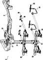
图1是根据本发明一个实施方案的中颜面牵引器的透视图; Figure 1 is a perspective view of a mid-face retractor according to one embodiment of the present invention;
图2是根据本发明一个实施方案的环组件的透视图; Figure 2 is a perspective view of a ring assembly according to one embodiment of the present invention;
图3是图2中所示的环组件的顶视图; Figure 3 is a top view of the ring assembly shown in Figure 2;
图4A是图2和3中所示的环组件之侧部构件的顶视图; Figure 4A is a top view of the side members of the ring assembly shown in Figures 2 and 3;
图4B是图4a中所示的侧部构件的底视图; Figure 4B is a bottom view of the side member shown in Figure 4a;
图4C是图4b中所示的侧部构件的截面图; Figure 4c is a cross-sectional view of the side member shown in Figure 4b;
图4D是图4a-4c中所示的侧部构件的侧视图; Figure 4D is a side view of the side member shown in Figures 4a-4c;
图5A是图2和3中所示的环组件之安装板的侧视图; Figure 5A is a side view of the mounting plate of the ring assembly shown in Figures 2 and 3;
图5B是图5A中所示的安装板的顶视图; Figure 5B is a top view of the mounting plate shown in Figure 5A;
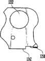
图6A是图2和3中所示的环组件之连接毂的透视图; Figure 6A is a perspective view of the connecting hub of the ring assembly shown in Figures 2 and 3;
图6B是图6A中所示的连接毂的前视截面图; Figure 6B is a front cross-sectional view of the connection hub shown in Figure 6A;
图6C是图6A和6B中所示的连接毂的侧视图; Figure 6C is a side view of the connection hub shown in Figures 6A and 6B;
图7是图1中所示的中间调整组件的透视图; Figure 7 is a perspective view of the intermediate adjustment assembly shown in Figure 1;
图8是图1、2、3和7中所示的中间调整组件和环组件的顶视图; Figure 8 is a top view of the intermediate adjustment assembly and ring assembly shown in Figures 1, 2, 3 and 7;
图9是图1、2、3和7中所示的中间调整组件和环组件的侧视图; Figure 9 is a side view of the intermediate adjustment assembly and ring assembly shown in Figures 1, 2, 3 and 7;
图10是本发明中间调整组件的另一实施方案; Fig. 10 is another embodiment of the intermediate adjustment assembly of the present invention;
图11是水平横梁组件的一个实施方案的透视图; Figure 11 is a perspective view of one embodiment of a horizontal beam assembly;
图12是水平横梁组件另一实施方案的透视图; Figure 12 is a perspective view of another embodiment of a horizontal beam assembly;
图13A是水平横梁组件之中间夹具的透视图; Figure 13 A is the perspective view of the middle clamp of horizontal beam assembly;
图13B是水平横梁组件之中间夹具的正视图; Fig. 13B is the front view of the intermediate fixture of horizontal beam assembly;
图14A是图12中所示水平横梁组件的转体型牵引器夹具的透视图; Figure 14A is a perspective view of the swivel-type retractor clamp of the horizontal beam assembly shown in Figure 12;
图14B是图14A中所示牵引器夹具的截面图; Figure 14B is a cross-sectional view of the retractor clamp shown in Figure 14A;
图15A图12中所示水平横梁组件之牵引器夹具的顶部的透视图; Figure 15A is a perspective view of the top of the retractor clamp of the horizontal beam assembly shown in Figure 12;
图15B是图15A中所示牵引器夹具之顶部的截面图; Figure 15B is a cross-sectional view of the top of the retractor clamp shown in Figure 15A;
图15C是图15A中所示牵引器夹具之顶部的侧视图; Figure 15C is a side view of the top of the retractor clamp shown in Figure 15A;
图16A是图12中所示牵引器夹具之底部的正视图 Figure 16A is a front view of the bottom of the retractor clamp shown in Figure 12
图16B是图16A中所示牵引器夹具之底部的侧视图 Figure 16B is a side view of the bottom of the retractor clamp shown in Figure 16A
图17是图1中所示上颌骨脚撑板组件的透视图; Figure 17 is a perspective view of the maxillary footrest assembly shown in Figure 1;
图18是图1中所示颧骨脚撑板组件的透视图。 18 is a perspective view of the zygomatic foot support assembly shown in FIG. 1 . the
优选的实施方案 preferred implementation
为了促进对本发明原理的理解,将参照图1中所示的示例性、非限制性的实施方案。中颜面牵引器10是一种外用设备,用于附着到患者的头盖骨和中颜面区域以进行骨生成治疗,从而逐渐地拉长颅面骨骼的一部分或多个部分。如图所示,中颜面牵引器10包括:用于接合患者头盖骨的外用环组件20、包括附着于其上的垂直中间杆150的中间调整组件100、包括至少一个牵引螺杆270的至少一个水平横梁组件200,和至少一个安装到将要牵引的目标颅面骨上的脚撑板组件300。中颜面牵引器10还可以包括各种 不同的独立的调整机构,这些独立的调整机构使中颜面牵引器10能够适合大多数患者而不论他们个人的身体特征如何。 To facilitate an understanding of the principles of the invention, reference will be made to an exemplary, non-limiting embodiment shown in FIG. 1 . The mid-facial retractor 10 is an external device for attachment to the cranial and mid-facial regions of a patient for osteogenetic treatment to gradually lengthen a portion or portions of the craniofacial skeleton. As shown, the mid-face retractor 10 includes an
中颜面牵引器10还可以包括各种不同的独立的调整机构,与当前可以获得的装置相比,使外科医生可以更大、更精确地控制牵引矢量。也就是说,中颜面牵引器10可以给外科医生提供额外的前后(anterior-posterior)和内外侧(medial-lateral)调整,从而使外科医生可以更精确和准确地控制牵引方向。此外,中颜面牵引器10还可以使外科医生在牵引治疗已经开始后容易地和准确地改变牵引方向,从而使外科医生如果需要能够在治疗过程中的任何时间重新调整牵引的最终矢量。 The mid-face retractor 10 may also include various independent adjustment mechanisms, allowing the surgeon greater and more precise control over the traction vector than currently available devices. That is, the mid-face retractor 10 can provide the surgeon with additional anterior-posterior and medial-lateral adjustments, allowing the surgeon to more precisely and accurately control the direction of the traction. In addition, the midface retractor 10 also allows the surgeon to easily and accurately change the direction of traction after the traction treatment has begun, thereby enabling the surgeon to readjust the final vector of traction at any time during the treatment if desired. the
环组件 ring components
环组件可以是一种附着在患者头部为牵引元件提供刚性支撑结构的构架。环组件是现有技术中已知的,且任何已知的环组件可以与本发明结合使用。例如,该环组件可以是单一的整体件,其环绕并附着于患者的头部而没有任何调整机构。 The ring assembly may be a framework attached to the patient's head to provide a rigid support structure for the traction elements. Ring assemblies are known in the art, and any known ring assembly may be used in conjunction with the present invention. For example, the ring assembly may be a single, integral piece that wraps around and attaches to the patient's head without any adjustment mechanism. the
另外,如图2和图3所示,环组件20可以是一个U形构件,该构件包括两个各自具有多个头盖骨固定孔71的安装板70、两个侧部构件50、和一个用于相互连接两个侧部构件50并将环组件20连接到中间调整组件100上的中间连接毂30。此外,环组件20可以包括若干调整机构,这些调整机构使环的尺寸可以调节以适应单个患者的头部。也就是说,环组件20可以单独地或组合地结合内外侧(medial-lateral)调整机构以调整环组件的总宽度“W”的,和位于每个侧部构件50内的前后(anterior-posterior)调整机构以调整环组件20的总长度“L”。 In addition, as shown in FIGS. 2 and 3, the
当从上面看时,环组件20的每一个侧部构件50通常是一个“L”形的构件,每一个侧部构件50被设计成环绕患者头部的各自一侧。侧部构件50可以被设计成提供环组件20流线型的外形且同时提供最轻的可能结构。如图4A-4D所示,每一个侧部构件50可以包括前部52和后部54,而且前部52可以成圆角,以便为患者提供更合身、更好看、更舒适的环组件20。前部52还可以被构建成与连接毂30的一侧接合(参看图6A-6C),而后部54可以被构建成与安装板70接合。 Each
如图5A和5B最优地所示,安装板70可以被设计成架在患者的耳朵上以通过现有技术中已知的任何方法将环组件20固定在患者的头骨上。因此,尽管安装板70可以采取任何形状、构造和轮廓,但每一个安装板70通常可以是一个具有沿其底表面78形成的弓形式样的矩形板,该弓形式样提供环绕患者耳朵的改进的轮廓配合。 As best seen in FIGS. 5A and 5B , mounting
安装板70可以包括多个延伸穿过安装板70到达另一面的孔71,从而使头骨固定装置(未示)可以被插入到位于患者耳朵上方的头骨的颞骨和/或顶骨的不连续位置上,将该板固定于头骨。孔71可以具有适合接纳头骨固定装置的任何大小、形状或尺寸。孔71还可以带螺纹,从而使环组件20可以通过带外螺纹的头骨固定销(未示)固定到患者的头部。头骨固定销可以插入并穿过位于患者耳朵上方的安装板70内的孔71。带螺纹的孔71与带螺纹的头骨固定销的联合使用使得固定销可以在将环组件20置于患者头盖骨周围之前部分地旋入安装板70,从而简化安装过程。可选择的,固定销可以具有适合刺穿皮肤的细微尖端,从而不需要在患者的头皮上进行预切口。可选择的,头骨固定装置可以包括自钻孔(self-drilling)安装销(未示),其可以通过骨头螺纹主动地与头骨接合。此外,中颜面牵引器10还 可以包括定位销(未示),其尺寸和构造被设计成相对患者头皮对环组件20的位置进行临时定位。一旦适当地定位后,可以移除定位销并以永久的头骨固定装置取代。 Mounting
孔71可以被定向而使其轴线垂直于安装板70的平面。可选择的,孔71可以与安装板70的平面成角度,这样一个角度的度数是适合具体患者和/或治疗的度数,例如,孔可以与安装板的平面成15度角。安装板70还可以同时具有直孔72和有角度的孔73,其中,直孔72通常位于板70的中部而有角度的孔73位于沿板70的外部边缘。然而,直孔72和有角度的孔73的任何组合和排列都是可以的。 The
可以通过现有技术中任何已知的方法包括但不限于焊接、胶粘等将安装板70连接到侧部构件50上。可选择的,安装板70可以与环组件20的侧部构件50一体成型或者可以将它们完全省略,代之以包含多个用于接纳头骨固定装置的孔71的侧部构件50。安装板70还可以可调整地连接于侧部构件50上,从而使环组件20的总长度“L”可以被调整。在一个实施方案中,侧部构件50的后部54的底表面56可以具有一个突起58,用于与安装板70的顶面74上的狭槽76接合,从而使安装板70在前后(anterior-posterior)方向上可以沿着侧部构件50滑动。例如,突起58可以是一个楔形榫头,用于与安装板70的顶面74上的相应沟槽接合。此外,每一个侧部构件50的后部54还可以包括内螺纹孔60,用于与调整螺杆90的第一端接合。安装板70的顶面74可以包含向上延伸部82,该向上延伸部82具有可旋转地接纳调整螺杆90之第二端的孔84。调整螺杆90可以被轴向地保持在安装板孔84内,从而使调整螺杆90的旋转会使侧部构件50相对于调整螺杆90和安装板70移动。因而,旋转调整螺杆90可以使侧部构件50沿着安装板70 在狭槽76内移动。在第一方向上旋转调整螺杆90可以使安装板70拉近侧部构件50,从而减小环组件20的总长度“L”。在第二方向上旋转调整螺杆90可以使安装板70与侧部构件50进一步反向移动,从而增加环组件20的总长度“L”。如图所示,调整螺杆90可以使环组件20的总长“L”增加而超过其未延伸长度最多大约25毫米(mm)。优选地,如图5A所示,安装板70可以具有刻度例如标记80,以帮助外科医生计算调整的数值。 Mounting
连接毂 connection hub
如前所述,每一个侧部构件50可以具有一个前部52,其在安装时邻近患者前额的中部。连接毂30可以将每一个侧部构件50的前部52相互连接在一起,同时提供一个机构通过一个中间调整组件100(详述见下文)将环组件20连接到牵引装置其余部分的机构。通常如图4D所示,侧部构件50的高度“h”从后部54到前部52可以逐渐增加,从而方便将侧部构件50连接于连接毂30,同时使重量减到最小并使环的总体外观成流线型。 As previously mentioned, each
如图6A-6C所示,连接毂30通常包括一个中间件32及一个用于调整环组件20的总宽度“W”的横向调整机构33。中间件32可以是现有技术中任何已知的形状,包括但不限于正方形、矩形等。在说明性实施方案中,中间件32为T形轮廓,具有一个顶部34及一个底部36。顶部34可以被构造成与中间调整组件100接合,而底部36可以被构造成接纳横向调整机构33。 As shown in FIGS. 6A-6C ,
中间件32的底部36可以包含一个与横向调整机构33接合的机构。横向调整机构33可以是现有技术中适合于调整相互连接构件的位置的任何已知机构,包括但不限于齿轮和齿条、标准螺杆、蜗轮型机构等。在说明性 实施方案中,中间件32的底部36包含用于接纳框架调整螺杆44的水平孔46,该框架调整螺杆44是在两端具有反手螺纹的双纹螺钉,其端部与侧部构件50的前部52内的相应孔53配合。在连接毂30内的水平孔46还可以装配轴承件46a,该轴承件46a的尺寸和构造被设计成用于环绕并配合调整螺杆44。在调整螺杆44置于轴承件46a内后,轴承件46a被压配并旋进水平孔46内,从而相对于连接毂30固定调整螺杆44的轴向位置。如图所示,在调整螺杆44上的沟槽47的任一侧均可以安置一个轴承件46a。 The bottom 36 of the middle piece 32 may contain a mechanism that engages the lateral adjustment mechanism 33 . Lateral adjustment mechanism 33 may be any mechanism known in the art suitable for adjusting the position of interconnected members, including but not limited to pinion and rack, standard screw, worm gear type mechanisms, and the like. In the illustrated embodiment, the bottom 36 of the middle piece 32 includes a
此外,如图4C最优地所示,侧部构件50内形成的孔53可以包括一个较大直径的无螺纹部53a和一个较小直径的螺纹部53b。螺纹部53b的尺寸和构造可以被设计成与调整螺纹杆44螺纹接合,而无螺纹部53a的尺寸和构造可以被设计成用于接纳工具,例如螺丝刀、棘轮等,用于与位于调整螺杆44之任一端的工具接合机构45接合,使得使用者可以在所需方向上旋转调整螺杆44。当被安装到侧部构件50上时,框架调整螺杆44的端部可以通过延伸穿过各个侧部构件50的孔53来调整。 Additionally, as best shown in FIG. 4C, the
然后,在第一方向上旋转框架调整螺杆44可以将环组件20的侧部构件50拉向连接毂30,从而减小环组件20的总宽度“W”。相似地,在第二方向上旋转框架调整螺杆44可以使环组件20的侧部构件50远离连接毂30移动,从而增加环的总宽度“W”。框架调整螺杆44可以在连接毂30的每一侧允许大约0毫米到大约40毫米的调整范围。 Rotating the
为了防止侧部构件50相互之间和相对于连接毂30发生扭曲并使环20可以进行平滑的横向调整,横向调整机构33还可以具有至少一个、优选为两个加强杆66(如图2所示),该加强杆平行于调整螺杆44并可以位于调整螺杆的任一侧。然而,可以使用任何数量和构造的加强杆66。每一个杆 66可以被设计和构造成被装配在侧部构件50和连接毂30内的相应凹槽68、69内,使得杆66通常可以在凹槽处68、69内滑动。因此,当旋转调整螺杆44时,侧部构件50可以沿着杆66滑动并在其上被引导作平滑移动。 In order to prevent the
连接毂30和侧部构件50还可以具有锁定机构31,用于在环组件20的总宽度“W”确定后锁定该总宽度。尽管可以使用任何数目的锁定机构31,如图3最优地所示,牵引器10优选地包括三个锁定机构31,在每个侧部构件50上有一个,在连接毂30上有一个。锁定机构31可以是现有技术中已知适于固定可移动构件之相对位置的任何机构,包括但不限于标准固定螺钉。然而,如图6C最优地所示,锁定机构31可以包括一个螺钉48和一个杆锁49。螺钉48和杆锁49的尺寸和构造被设计成可以延伸穿过毂30内的孔,使得杆锁49接触加强杆66的外部圆周。螺钉48的尺寸和构造被设计成可以延伸穿过杆锁49并进入调整螺杆44内的沟槽47中。此后,旋转螺钉48可以使杆锁49压抵在加强杆66上,从而固定相对于连接毂30加强杆66的位置。尽管已经结合连接毂30描述了锁定机构31,但是如前所述,每一个侧部构件50也可以包括与上述锁定机构相同的锁定机构31。 The connecting
连接毂30的顶部34可以包括用于将连接毂30连接到中间调整组件100的附着机构。该附着机构可以是现有技术中任何已知的装置,包括但不限于螺纹连接、焊接等。在说明性实施方案中,中间件32之顶部34的较高表面38可以具有突起40,该突起40通常被定向成与框架调整螺杆44的轴线(即当装置被安装到患者上时的内外侧轴线)平行,以与位于中间调整组件100上的相应狭槽112接合。突起40可以是楔形榫头,以与位于中间调整组件100上的相应沟槽接合,从而使外科医生可以沿着连接毂30的内外侧(medial-lateral)轴线滑动中间调整组件100。因此,外科医生可以使用这 种附着机构将垂直中间杆150(详述见下文)的横向位置调整到患者面部前面的一个理想位置,从而将对患者视野的影响减到最小。连接毂30的顶部34的尺寸和构造被设计使其可以同时接纳并接合两个中间调整组件100,从而使,外科医生需要,他/她可以安装两个中间调整机构100和两个相应的垂直中间杆150。因而提供了使外科医生能够更大、更精确地控制牵引矢量的额外调整机构。还能够使外科医生将垂直中间杆150从患者的中间视野朝向患者视野的外围移动,从而将对患者视野的影响量减到最小。 The top 34 of the
连接毂30还可以进一步包括用于接纳中间调整机构100上的固定螺钉114的沟槽(未示),从而使在当中间调整机构100和相应的垂直中间杆150被合适定位时,旋转固定螺钉114来固定中间调整机构100相对于连接毂30的横向位置。优选地,固定螺钉114和沟槽的尺寸和构造被设计成使固定螺钉114可以被松开,以使中间调整组件100能够相对于连接毂30移动。然而,即使处于松开状态,固定螺钉114和沟槽的尺寸和构造也应被设计成使固定螺钉114不能从沟槽中取下,从而防止连接毂30与中间调整机构100分离。 The connecting
侧部构件50、连接毂30和加强杆66可以由现有技术中任何已知的材料制造,包括但不限于钛、铝、不锈钢、聚合物、碳素纤维等。连接毂30优选是镀钛的,钛提供润滑,有利于毂30与中间调整机构100之间的可滑动性移动。 The
中间调整组件 Intermediate adjustment components
如图1最优地所示,中间调整组件100将环组件20连接到垂直中间杆150,从而将垂直中间杆150及与它联结的水平杆、夹具及牵引螺杆支撑在 患者面前的期望位置。可以使用任何机构来连接环组件20与垂直中间杆150,包括但不限于例如图10中所示的单一整体件。然而优选地,如图7最优地所示,中间调整组件100可以结合多个独立的调整机构,从而可以相对于调整环组件20调整垂直中间杆150。也就是说,中间调整组件100可以单独地或组合地围绕上下(superior-inferior)轴线、围绕内外侧(medial-lateral)轴线旋转垂直中间杆150,还可以对垂直中间杆150进行内外侧(medial-lateral)和垂直调整。 As best shown in FIG. 1 , the
如图7所示,中间调整组件100可以包括前部102和后部110。中间调整组件100的后部110与连接毂30的附着装置配合。也就是说,如前所述,中间调整组件100的后部110可以具有狭槽112,用于接合位于连接毂30顶部34的较高表面38上的相应突起40。该突起可以是楔形榫头,其与位于中间调整组件100上的相应沟槽接合。这样使外科医生可以沿着连接毂的内外侧(medial-lateral)轴线滑动中间调整组件100。因而外科医生可以将垂直杆150的横向位置调整到患者面前的期望位置,以将对患者视野的影响减到最小。如前所述,后部110还可以具有固定螺钉114,当外科医生选定垂直杆150的内外侧(medial-lateral)位置和垂直位置后用固定螺钉114相对于连接毂30固定中间调整组件100的横向位置。 As shown in FIG. 7 ,
中间调整组件100的前部102可以从环组件20向前向外延伸,并且通过孔104与垂直中间杆150的上部配合,该垂直中间杆150的下部连接于水平横梁组件200(详述见后)。孔104可以具有轴线,该轴线通常定向为基本垂直于中间调整组件100的顶面。孔104可以具有非圆形或钥匙样(keyed)的横截面,用于与非圆形或钥匙样(keyed)的垂直中间杆配合。然而,优选地,杆150具有沿其外表面纵向延伸的狭槽(未示),该狭槽的尺寸和构 造被设计成与中间调整组件100内的固定螺钉106配合。固定螺钉106与该狭槽的配合可以防止垂直中间杆150相对于中间调整组件100旋转。而且,当杆150被外科医生适当定位后,旋转固定螺钉106还可以相对于中间调整组件150固定垂直中间杆150的轴向位置。 The
如前所述,中间调整组件100还可以单独地或组合地包括多个调整机构,以使垂直中间杆可以相对于环组件20进行额外调整。也就是说,中间调整组件100可以被构造成使垂直中间杆150可以围绕看上下(superior-inferior)轴线和内外侧(medial-lateral)轴线进行角度调整(因材施教而可以大范围地对附着其上的水平横梁组件200进行角度调整)。这种角度调整可以由现有技术中任何已知的机构来实现,包括但不限于齿轮和齿条、球形接头、棘轮和棘爪型组件、凸轮和从动轮类型组件等。可选择的,如图10所示,中间调整组件100还可以是将环组件20与垂直中间杆150连接的不可调整的单一件。然而,优选地,如图7所示,中间调整组件100可以包括多个独立的调整机构,以使垂直中间杆150可以相对于环组件20进行调整。如图所示,中间调整组件100可以包括至少一个位于中间调整组件100的前部102与后部110之间的蜗轮机构。尽管可以使用任何数目的蜗轮机构,但如图所示的中间调整组件100可以包括两个蜗轮机构116、118。蜗轮机构116、118可以具有蜗杆122、124,蜗杆122、124可以位于中间调整组件100的顶面或侧面。蜗轮机构116、118的使用使外科医生利用蜗杆122、124的每一转将蜗轮和垂直杆150旋转一个不连续的、精确的量,从而可以精确控制对牵引矢量的调整。可以选择蜗杆和蜗轮螺纹的螺距,使得蜗杆122、124每一度的旋转提供所期望的齿轮移动量,这也是一种设计选择。 As previously mentioned, the
如图所示,第一蜗轮116使垂直中间杆150可以进行上下(superior-inferior)旋转(即围绕内外侧轴线旋转),而第二蜗轮118使垂直中间杆150可以进行内外侧(medial-lateral)旋转(即围绕上下轴线旋转,上下轴线是垂直于水平通过佩戴者身体的平面的轴线)。如图8和图9所示,中间调整组件100的蜗轮机构116、118可以允许大约正负30度的内外侧(medial-lateral)旋转和正45度到负30度的上下(superior-inferior)旋转,虽然其它的旋转范围也是可能的。 As shown, the
每一个蜗轮机构116、118还可以包括固定螺钉120、126。一旦紧固,固定螺钉120、126可以防止中间调整组件100的任何进一步移动。 Each
垂直中间杆 vertical center pole
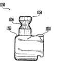
如图1中所示,垂直中间杆150可以是具有第一端152和第二端154的杆。第一端152可滑动地与中间调整组件100的孔104接合,而第二端154可滑动地与位于水平横梁组件200上的中间夹具202接合(详述见下文)。垂直中间杆150使水平横梁组件200和中间调整组件100可以被定位于沿其长度的几乎任何位置,因而在确定水平横梁组件200、牵引螺杆270和骨接合部分302的位置时提供最大的自由度。一旦垂直中间杆150被适当定位后,可以分别紧固中间调整组件100和中间夹具202内的固定螺钉106、206,以防止垂直中间杆150的任何进一步移动。 As shown in FIG. 1 , vertical
如前所述,垂直中间杆150优选地具有沿其外表面延伸的纵向狭槽,该狭槽的尺寸和构造被设计成与中间调整组件100内的固定螺钉106和中间夹具202内的固定螺钉206配合(详述见下文),从而防止垂直中间杆150相对于中间调整组件100和相对于中间夹具202旋转。 As previously mentioned, the vertical
垂直中间杆150可以由现有技术中任何已知的材料制造而成,包括但不限于铝、钛、镍钛诺、聚合物、碳素纤维等。 Vertical
水平横梁组件 Horizontal Beam Assembly
水平横梁组件200连接垂直中间杆150与牵引螺杆270,牵引螺杆270本身连接于脚撑板组件300。如图1所示,中颜面牵引器10可以包括两个水平横梁组件200,一个用于牵引上颌骨,另一个用于牵引颧骨。然而,可以使用任何数目的水平横梁组件200。例如,在Lefort I型外科治疗中,通常只需要一个水平横梁组件200来牵引上颌骨。 The
水平横梁组件200可以提供对牵引矢量进行额外调整的机构。水平横梁组件200可以包括对牵引螺杆270的位置提供横向调整(lateraladjustment)、横向的旋转(transverse rotation)、和控制上下(superior-inferior)方向的机构。
如图11及12最优地所示,水平横梁组件200包括中间夹具202、水平杆212、和两个牵引器夹具230。中间夹具202将垂直中间杆150与水平杆212连接。如图13A和13B所示,中间夹具202可以是块状构件,该构件具有两个延伸穿其而过的非交叉孔,即垂直孔204和水平孔208。垂直孔204通常沿着上下(superior-inferior)轴线延伸穿过中间夹具202,而水平孔208通常沿着内外侧(medial-lateral)轴线穿过中间夹具202。如前所述,中间夹具202包括固定螺钉206,用于接合垂直中间杆150中的狭槽,从而防止垂直杆150与中间夹具202之间的旋转。一旦紧固,固定螺钉206防止中间夹具202相对于垂直中间杆150移动。水平孔208可以是与圆柱形水平杆212配合的圆形,从而使水平杆212相对于中间夹具202可以旋转。中间夹具 202还可以包括与水平杆212接合的固定螺钉210。一旦紧固,固定螺钉210防止中间夹具202相对于水平杆212的移动。 As best shown in FIGS. 11 and 12 , the
水平杆212通常沿着垂直于垂直中间杆150的纵向轴线的轴线定向。水平杆212使中间夹具202与牵引器夹具230相互连接,如图所示,该牵引器夹具230可以位于中间夹具202的每一侧。然而,可以使用任何数目和构形的牵引器夹具230。水平杆212具有第一端214、第二端216及位于它们之间的中间部分218。第一端214和第二端216各自可以可滑动地与各牵引器夹具230内的孔232接合,而水平杆212的中间部分218可滑动地与中间夹具202的水平孔208接合。水平杆212的中间部分218沿其长度的至少一部分可以具有沟槽220,用于接纳并接合中间夹具202的水平固定螺钉210。沟槽220可以与固定螺钉210相互作用,以阻止水平杆212相对于中间夹具202旋转。 The
如图所示,牵引器夹具230可以包括一个块状构件,该块状构件具有用于接纳水平杆212的水平孔232及用于接纳牵引螺杆270的牵引螺杆孔236。水平孔232可以是圆形的,与水平杆212的圆形横截面配合。这种构形使牵引器夹具230可以被定位于沿水平杆212长度的几乎任何位置,因而外科医生可以调整牵引螺杆270和附着于其上的脚撑板300的横向位置。此外,圆形的水平孔232使外科医生可以沿水平杆212的轴线旋转牵引器夹具230和牵引螺杆,从而使外科医生可以改变牵相对于水平杆212引螺杆270的角度,因而对牵引的角度和方向提供了额外的控制,特别是在上下(superior-inferior)方向上。每一个牵引器夹具230还可以具有固定螺钉234,当紧固时,该固定螺钉234防止牵引器夹具230相对于水平杆212移动和旋转。 As shown,
牵引螺杆孔236通常具有垂直于水平杆212之轴线定向的轴线。牵引螺杆孔236可以被构造成接纳牵引螺杆270和牵引螺母238,例如六角螺母等,用于螺纹接合牵引螺杆270。因此,旋转牵引螺母238可以拖曳牵引螺杆270通过螺杆孔236,从而牵引所附着的骨节段(详述见下文)。 Pull screw bore 236 generally has an axis oriented perpendicular to the axis of
参看图12、14A、14B、15A-15C、16A和16B,每个牵引器夹具1230还可以具有转体特征。该转体性牵引器夹具1230可以由多个部件构成,每一个部件可以相对于与它联结的部件回转。如图所示,转体性牵引器夹具1230可以包括顶部件1240和底部件1250,顶部件1240与水平杆1212联结,底部件1250与牵引螺杆1270联结。也就是说,如图14A、14B、15A-15C、16A及16B最优地所示,旋转性牵引器夹具1230的顶部件1240可以具有可滑动地接合水平杆1212的水平孔1232,而底部件1250可以具有接合牵引螺杆270的牵引螺杆孔1236。顶部件1240和底部件1250可以通过现有技术中已知的任何适合方式连接,以使底部件1250及附着其上的牵引螺杆270可以相对于顶部件1240及所联结的水平杆212回转。底部件1250可以围绕一轴线回转,该轴线通常平行于并偏移垂直中间杆150的轴线。然而,回转轴线是一种设计选择,可以提供其它的回转轴线。使用回转性牵引器夹具1230给外科医生在固定牵引螺杆270的位置上及对最终牵引方向的控制上提供了另一种调整选择。优选地,转体性夹具1230可以允许正负20度的旋转。 12, 14A, 14B, 15A-15C, 16A, and 16B, each
顶部件1240可以包括从顶部件1240的底表面1242延伸的垂直孔1244,用于接纳从下部件1250的顶面1252延伸出来的垂直柱1254。垂直柱1254和垂直孔1244具有匹配的横截面,因而使底部件1250可以相对于顶部件1240旋转或回转,并因此使牵引螺杆270可以横向旋转。顶部件1240还可 以包含固定螺钉1246,该固定螺钉1246具有与垂直柱1254上的沟槽1256相配合的尖端,当紧固时,固定螺钉1246防止顶部件1240与底部件1250之间的进一步旋转或回转,从而防止牵引螺杆270进一步旋转。顶部件1240的底表面1242和底部件1250的顶面1252还可以包含联锁齿1258,用于临时地相对于顶部件1240锁住即固定底部件1250。 The
进一步优选地,顶部件1240和垂直柱1254上形成的沟槽1256的尺寸和构造被设计成接纳销1270,如图14B最优地所示。该销1270的尺寸和构造被设计成与垂直柱1254和在顶部件1240上形成的垂直孔1244配合,以在固定螺钉1246松开时防止牵引器夹具1230的顶部件1240与底部件1250分离。 Further preferably,
可选择的,转体性夹具1230的顶部件1240和底部件1250可以颠倒。也就是说,转体性夹具1230的顶部件1240可以包含与牵引螺杆270接合的牵引螺杆孔1236,而底部件1250可以具有与水平杆1212可滑动地接合的水平孔1232。 Alternatively, the
牵引螺杆270通常可以同时垂直于垂直中间杆150和水平杆212定向。然而,转体型牵引器夹具1230可以相对水平杆1212的轴线对这种定向进行调整。如前所述,牵引螺杆270可以包括向内指向患者面部的远端272和与牵引器夹具230接合的近端274。优选地,牵引螺杆270包括从远端272延伸到近端的蚀刻的刻度即标记,以帮助外科医生确定牵引的精确量。每一个牵引螺杆270的远端272可以包括钻成或以其它方式形成的孔276。孔276通常被构造成可以接纳金属线285,该金属线可以将牵引螺杆270与相应的脚撑板组件300相互连接。使用金属线285将牵引螺杆270与骨接合部分302相互连接(详述见下文)使得中颜面牵引器10可以被容易地分离,且 不需要进行第二次切割以去除骨接合部分302。也就是说,骨接合部分302可以被构建成外形不引人注意,从而如果需要,它们可以附着在患者的上颌骨和颧骨上而几乎看不见,从而不需要进行第二次切割以去除骨接合部分302。而且,骨接合部分302可以由生物可吸收材料制造,在治疗之后,该材料可以留在患者体内。生物可吸收的脚撑板可以随时间自然退化,因此不需要将它们移除。金属线的使用使骨接合部分302可以容易地与牵引螺杆270分离,从而使中颜面牵引器10可以容易地分离并从患者的头盖骨移除。金属线285可以由现有技术中已知的任何适合材料制成,包括但不限于24或26规格的不锈钢丝。然而,金属线285的使用不是关键性的,牵引螺杆270也可以与骨接合部分302直接接合。
脚撑板组件 foot plate assembly
脚撑板组件300将牵引螺杆270连接到将要牵引的目标骨节段上。如图1所示,中颜面牵引器10可以有四个脚撑板组件300。然而,如前所述,这个数目不是关键性的,可以使用任何数目的脚撑板组件300。中颜面牵引器10可以包括上颌骨和颧骨脚撑板组件,它们将目标骨节段与各自的牵引螺杆270连接。上颌骨和颧骨脚撑板组件通常可以被构造成使中颜面牵引器10更容易附着在目标骨节段上并且容易从目标骨节段移除,使患者的舒适性最大化。
通常上颌骨脚撑板组件310通常将正好位于牙体上方的上颌骨节段连接到水平横梁组件200上。当使用多横梁组件200时,上颌骨脚撑板组件310通常连接到较低的水平横梁组件200上。颧骨脚撑板组件340将颧骨节段连接到较高的横梁组件200(当使用多横梁组件时)。 Typically the maxillary footrest assembly 310 connects the segment of the maxilla generally just above the tooth to the
脚撑板组件300通常包括与上颌骨或颧骨直接接合的骨接合部分302。骨接合部分302可以是脚撑板,也可以是如外科医生所期望的、具体骨头所允许和/或治疗所需要的适合连接到颧骨、上颌骨、鼻、眼眶下缘、或梨形孔上的多种形状。骨接合部分302可以具有一个或多个穿其而过的孔304,用于接纳骨接合螺钉(未示),以将该骨接合部分固定到骨头上。孔304的数目是一种设计选择。骨接合部分302可以由现有技术中已知的任何适合的材料制造,包括但不限于钛、生物可吸收材料等。可选择的,上颌骨脚撑板组件310的骨接合部分302可以是刚性的口腔内夹板,该口腔内夹板使中颜面牵引器10可以与患者牙齿接合,从而不需要将骨螺钉安装到上颌骨内。可以使用现有技术中的任何已知的口腔内夹板。在一个实施方案中,根据患者的年龄,口腔内夹板可以包括安装在初始或再生臼齿上的牙列矫形带。该牙列矫形带可以被弯曲以与大多数(如果不是所有的)与上颌骨联结的牙齿紧密接触。口腔内夹板可以进一步包括从牙列矫形带上伸出的连接金属线。该连接金属线便于牵引螺杆270直接连接或通过金属线285连接。牙列矫形带和连接金属线可以由现有技术中任何已知的适合材料制成,包括但不限于不锈钢丝,例如,0.045或0.050的不锈钢丝。 The
如图17所示,上颌骨脚撑板310还可以包括牵引器接合部分320、牵引器杆312、和骨接合部分302(如上所述)。牵引器杆312通常用于将骨接合部分302连接到牵引器接合部分320,并具有第一端314和第二端316。牵引器杆312的第一端314连接到骨接合部分302上。这种连接可以通过现有技术中任何已知的方法来实现,包括但不限于焊接、螺钉连接、螺栓连接、机器螺钉连接、滑足(slip-foot)类型连接等。在列举的实施方案中,牵引器杆312和骨接合部分302可以通过螺钉318连接。螺钉318使牵引器 杆312可以在需要时被连接到骨接合部分302上或从其上取下,而不必从患者身上移除骨接合部分302。牵引器杆312的第二端与牵引器接合部分320接合。 As shown in FIG. 17, the maxillary foot support 310 may also include a retractor engagement portion 320, a retractor rod 312, and a bone engaging portion 302 (described above). The retractor rod 312 is generally used to connect the
牵引器杆312可以由现有技术中任何已知的材料制成,包括但不限于强度高但易于弯曲的材料,使外科医生可以将牵引器杆312塑造成任何需要的形状,以将对患者面部特征的影响减到最小。然而,材料仍然应该有足够强度以抵抗牵引过程中作用于其上的力所导致的变形。如图所示,牵引器杆312可以被弯曲成U形,当上颌骨脚撑板组件与上颌骨接合时,牵引器接合部分320可以位于患者口腔的外面,同时避开患者的嘴唇。 The retractor rod 312 can be made of any material known in the art, including but not limited to a strong yet easily bendable material, allowing the surgeon to mold the retractor rod 312 into any desired shape to provide greater stability to the patient. The influence of facial features is minimized. However, the material should still be strong enough to resist deformation caused by the forces acting on it during traction. As shown, the retractor rod 312 can be bent into a U shape, and when the maxillary footrest assembly is engaged with the maxilla, the retractor engaging portion 320 can be positioned outside the patient's mouth while avoiding the patient's lips. the
牵引器接合部分320将骨头接合部分302连接到牵引螺杆270上。这种连接可以通过现有技术中任何适合的已知方法实现。优选地,牵引器接合部分320可以是与牵引器杆312可滑动地接合的夹具321,从而使牵引器接合部分320可以被置于沿牵引器杆312长度的任何位置。如图所示,夹具321可以是包括基部322的单一部件夹具,该基部322具有两个延伸出来的臂324。基部322可以包括沿其长度一部分延伸的垂直狭槽326,该垂直狭槽326有内部加宽的卡爪区域327,该卡爪区域被设计成与牵引器杆312接合。垂直狭槽326使夹具321的臂324与牵引器杆312接合。臂324还可以包括用于接纳固定螺钉332的相应孔(未示),紧固固定螺钉332将臂部324拉在一起,从而将牵引器杆312夹持在臂之间,并防止夹具321相对于牵引器杆312进一步移动。此外,夹具321的基部322可以包括与金属线285接合的穿通的孔328,该金属线接着被连接到牵引螺杆270上,如图1最优地显示,且如前所述。 The retractor engaging portion 320 connects the
类似于上颌骨脚撑板组件310,颧骨脚撑板组件340包括骨接合部分 302,如上所述,用于与患者的颧骨接合。然而,不同于包括牵引器接合部分320和牵引器杆312的上颌骨脚撑板组件310,如图18所示,每一个颧骨脚撑板组件340可以包括具有第一端344和第二端346的金属线附着螺钉342。金属线附着螺钉342的第一端344的尺寸和构造被设计成与脚撑板组件300之骨接合部分302上的孔螺纹接合并延伸穿过该孔,使得螺钉342的第一端344还可以与患者的颧骨螺纹接合。这样使得金属线附着螺钉342以锐角与患者的骨头接合。螺钉344的第二端346可以包括具有孔350的增大的头部348,孔350是钻穿头部形成的并通过金属线285与牵引螺杆270接合。第二端346还可以包括位于其末端的工具接合机构,用于与螺丝刀、棘轮等接合,以便于相对于骨接合部分302安装和移除金属线附着螺钉342。 Similar to the maxillary footrest assembly 310, the
需要指出的是在此描述的上颌骨脚撑板组件310和颧骨脚撑板组件340及它们的设置只是优选的实施方案,如果需要,外科医生可以只使用上颌骨脚撑板组件310或只使用颧骨脚撑板组件340。此外,外科医生可以将颧骨脚撑板组件340附着在患者的上颌骨上,而将上颌骨脚撑板组件310附着在患者的颧骨上。最后,牵引螺杆270可以直接或通过金属线285连接于骨接合部分302。 It should be pointed out that the maxillary footrest assembly 310 and the
安装和移除方法及使用中的外用中颜面牵引器 Installation and removal methods and topical mid-face retractors in use
安装中颜面牵引器10,外科医生可以在开始时进行适当的切口将骨接合部分302安装到一个或多个目标骨节段上。接着,外科医生详细制订出适当的骨切开术,其可以是Lefort I、II、III或Monobloc布局。然后,骨接合部分302可以被安装在口腔内部(当连接到患者的上颌骨时)或体内(当连接到患者的颧骨时)。接着可以切除适当的骨头并关闭切口。 Installing the mid-facial distractor 10, the surgeon may initially make appropriate incisions to install the
随后,外科医生可以通过调整环组件20的横向和纵向调整机构将环组件20安装到患者的头部,并接着用置于侧部构件50上的孔71内的头骨固定销将环20与患者头部接合。可选择的,外科医生可以使用定位销来临时地相对于患者头皮定位环组件20的位置,直到中间调整组件100、水平横梁组件200、及牵引螺杆270被适当定位。 Subsequently, the surgeon can install the
接着,外科医生选择所需数目的水平横梁组件200,通常该数目取决于所执行的骨切开术的类型,例如Lefort II,、III和Monobloc型通常需要两个水平横梁组件,而Lefort I型通常只需要一个水平横梁组件。接看,可以将水平横梁组件200附着在垂直中间杆150上,该垂直中间杆150被附着到中间调整组件100上,该中间调整组件100可以已经连接到环组件20上。然后,使用特别是横向调整机构33和中间调整机构100调整和对准垂直中间杆150,以避免影响患者的视野。 Next, the surgeon selects the desired number of
接着,外科医生基于他/她所确定的适当牵引矢量,设置牵引螺杆270的角度。牵引螺杆270的角度可以通过调整垂直中间杆150、中间调整组件100、包括水平杆212和牵引器夹具230的水平横梁组件200的位置和角度来设置。接下来,如果使用金属线285,外科医生将金属线285附着到牵引螺杆270和脚撑板组件300上。其后,紧固每一个构件上的固定螺钉,从而将中颜面牵引器10固定在适当的位置。最后,外科医生紧固金属线285并确认所需骨节段的进展(advancement)。 Next, the surgeon sets the angle of the
需要指出的是,尽管如上所述的步骤是优选的安装步骤,但该安装步骤可以变化。例如,外科医生可以在制造任何切口之前详细制订出适当的骨切开术,或者外科医生可以选择在进行适当的骨切开之后安装骨接合部分302。此外,可以首先安装环组件20或者在骨切开完成之后再安装。对 安装程序任意数量变更仍然落在本发明的范围内。 It should be noted that although the steps described above are the preferred installation steps, the installation steps can vary. For example, the surgeon may detail the appropriate osteotomy prior to making any incisions, or the surgeon may choose to install the
一旦适当地安装,通过旋转牵引螺母238(该旋转依次地牵引所接合的骨节段)逐渐增加对骨节段的牵引。牵引螺杆270可以周期性地(例如每天地)旋转以渐增地牵引骨节段(通常为大约1毫米),直到获得期望的牵引。最终的牵引速度、节律、量和方向取决于外科医生。 Once properly installed, the distraction of the bone segments is gradually increased by rotating the distraction nut 238 (which in turn distracts the engaged bone segments).
此外,本发明使外科医生可以在牵引治疗的过程中,即牵引已经开始之后改变牵引螺杆270的牵引矢量。这种改变是通过改变牵引螺杆270的位置和/或角度来完成的。松开适当的固定螺钉并调整垂直中间杆150、中间调整组件100、或包括水平杆212和牵引器夹具230的水平横梁组件200的位置和/或角度以改变牵引螺杆270的位置和/或角度来完成。一旦适当地的重新定位后,如果必要,外科医生可以接着通过重新紧固固定螺钉来重新紧固金属线285并固定中颜面牵引器10的新位置。 Furthermore, the present invention allows the surgeon to vary the traction vector of the
为了移除中颜面牵引器10,如果使用了金属线285,外科医生可以剪断金属线285,从而将中颜面牵引器10与骨接合部分302分离。其后,可以松开头骨固定销(未示)并将整个组件从患者的头部移除。如果必要,外科医生接着去除骨接合部分302。可选择的,如前所述,骨接合部分302可以被设计成具有不显著的外形,从而如果需要,它们可以被留下来附着在患者上颌骨或颧骨上而几乎看不见,因而不需要进行移除骨接合部分302的第二切口。而且,骨接合部分302可以由生物可吸收材料制成,该材料在治疗后可以留在患者体内。生物可吸收的脚撑板随着时间会自然退化。 To remove the midface distractor 10, the surgeon may cut the wire 285, if used, thereby separating the midface distractor 10 from the
最后,需要指出的是本发明的中颜面牵引器10可以以包括各种部件的工具箱的形式提供,从而使外科医生可以根据每个患者个体的需要从多种部件中选择所需部件定制中颜面牵引器10。例如,工具箱可以包括数个水 平横梁组件200,从而使可外科医生可以选择要安装的横梁组件200的数目。可选择的,工具箱可以包括尺寸不同且具有不同螺距的牵引螺杆270,根据个体患者的需要,不同的螺距改变牵引螺杆270每一个单元旋转的牵引量。此外,工具箱可以包括各种不同尺寸、形状、材料的脚撑板300,不同尺寸的水平杆212和垂直杆15,转体和非转体的牵引器夹具230,可调整和不可调整的中间调整组件100等。 Finally, it should be pointed out that the mid-face retractor 10 of the present invention can be provided in the form of a tool box including various parts, so that the surgeon can select the required parts from a variety of parts according to the needs of each individual patient to customize the center. Facial retractor10. For example, the kit can include several
已经结合优选实施方案描述了本发明。然而,这些实施方案只是示例,本发明并不限于这些实施方案。本领域的技术人员将会理解本发明,在所附权利要求限定的本发明范围内可以容易地作出其它的改变和改进。因此,本发明仅由下面的权利要求限定。 The invention has been described in connection with the preferred embodiments. However, these embodiments are only examples, and the present invention is not limited to these embodiments. Those skilled in the art will appreciate the present invention and other changes and modifications can be readily made within the scope of the invention as defined in the appended claims. Accordingly, the invention is limited only by the following claims. the
Claims (9)
Applications Claiming Priority (3)
| Application Number | Priority Date | Filing Date | Title |
|---|---|---|---|
| US10/839,551 | 2004-05-04 | ||
| US10/839,551US7485121B2 (en) | 2004-05-04 | 2004-05-04 | Midface distractor |
| PCT/US2005/015592WO2005107620A2 (en) | 2004-05-04 | 2005-05-04 | Midface distractor |
Publications (2)
| Publication Number | Publication Date |
|---|---|
| CN101141925A CN101141925A (en) | 2008-03-12 |
| CN101141925Btrue CN101141925B (en) | 2012-09-26 |
Family
ID=35240374
Family Applications (1)
| Application Number | Title | Priority Date | Filing Date |
|---|---|---|---|
| CN2005800226488AExpired - LifetimeCN101141925B (en) | 2004-05-04 | 2005-05-04 | Midface distractor |
Country Status (12)
| Country | Link |
|---|---|
| US (2) | US7485121B2 (en) |
| EP (1) | EP1744688B1 (en) |
| JP (1) | JP4971143B2 (en) |
| KR (1) | KR101177436B1 (en) |
| CN (1) | CN101141925B (en) |
| AU (1) | AU2005240166A1 (en) |
| BR (1) | BRPI0510602B8 (en) |
| CA (1) | CA2565397C (en) |
| ES (1) | ES2534525T3 (en) |
| NZ (1) | NZ551590A (en) |
| WO (1) | WO2005107620A2 (en) |
| ZA (1) | ZA200609966B (en) |
Cited By (1)
| Publication number | Priority date | Publication date | Assignee | Title |
|---|---|---|---|---|
| CN104771217A (en)* | 2015-04-16 | 2015-07-15 | 高全文 | Dog mid-face bone traction device |
Families Citing this family (43)
| Publication number | Priority date | Publication date | Assignee | Title |
|---|---|---|---|---|
| US7485121B2 (en)* | 2004-05-04 | 2009-02-03 | Synthes (Usa) | Midface distractor |
| EP2085038B1 (en)* | 2008-02-01 | 2011-11-30 | Stryker Trauma SA | Ball joint for an external fixator |
| US8114077B2 (en)* | 2008-02-01 | 2012-02-14 | Stryker Trauma Sa | Clamping pin |
| EP2085037B1 (en)* | 2008-02-01 | 2013-07-24 | Stryker Trauma SA | Telescopic strut for an external fixator |
| WO2009097827A1 (en)* | 2008-02-06 | 2009-08-13 | Navas Maria Del Carmen | Orbit distractor |
| DE112009001275T5 (en)* | 2008-06-05 | 2011-04-14 | Dinkler Surgical Devices, Inc., Dayton | Head fixation device |
| DE102008034300A1 (en)* | 2008-07-23 | 2010-01-28 | Lucas Automotive Gmbh | Vehicle disc brake |
| US20100104999A1 (en)* | 2008-10-23 | 2010-04-29 | Bulloch Scott E | Apparatus, System, and Method for Intra-Oral Distraction |
| EP2405834B1 (en) | 2009-03-10 | 2016-07-20 | Stryker European Holdings I, LLC | External fixation system |
| WO2011016784A2 (en)* | 2009-08-06 | 2011-02-10 | Mohammed Aii Abbas Alkasem | Frontozygomatic anchored distraction osteogenesis device |
| US8858555B2 (en) | 2009-10-05 | 2014-10-14 | Stryker Trauma Sa | Dynamic external fixator and methods for use |
| CN101822568B (en)* | 2010-02-12 | 2012-02-15 | 中国人民解放军第四军医大学口腔医院 | Adjustable mid-face bone tractor and design method thereof |
| US9066733B2 (en) | 2010-04-29 | 2015-06-30 | DePuy Synthes Products, Inc. | Orthognathic implant and methods of use |
| US8435270B2 (en) | 2010-04-29 | 2013-05-07 | Synthes Usa, Llc | Orthognathic implant and methods of use |
| US8945128B2 (en) | 2010-08-11 | 2015-02-03 | Stryker Trauma Sa | External fixator system |
| US11141196B2 (en) | 2010-08-11 | 2021-10-12 | Stryker European Operations Holdings Llc | External fixator system |
| EP2417924B1 (en) | 2010-08-11 | 2015-07-01 | Stryker Trauma SA | External fixator system |
| US9265529B2 (en) | 2010-11-30 | 2016-02-23 | Nikolaj Wolfson | Orthopedic fixation systems and methods |
| US9265528B2 (en)* | 2010-11-30 | 2016-02-23 | Nikolaj Wolfson | Orthopedic fixation systems and methods |
| WO2013054157A1 (en)* | 2011-10-12 | 2013-04-18 | Rodriguez Gonzalez Jorge Mario | Independent multi-vector osteogenic distractor that is rigidly coupled to the craniofacial skeleton |
| US8840576B2 (en)* | 2012-03-26 | 2014-09-23 | Richard Pizzutillo | Brace installation device |
| US9101398B2 (en) | 2012-08-23 | 2015-08-11 | Stryker Trauma Sa | Bone transport external fixation frame |
| WO2014055202A1 (en)* | 2012-09-06 | 2014-04-10 | Solana Surgical LLC | External fixator |
| US9333053B2 (en) | 2013-08-07 | 2016-05-10 | Bandar ALYAMI | Orthodontic device |
| US9730731B2 (en) | 2014-02-27 | 2017-08-15 | Deka Products Limited Partnership | Craniofacial external distraction apparatus |
| FR3027791A1 (en)* | 2014-11-03 | 2016-05-06 | Yoomed | DEVICE FOR INDUCING OR CORRECTING MANDIBULAR GROWTH. |
| US10271914B2 (en) | 2015-02-11 | 2019-04-30 | University Of Utah Research Foundation | Microsurgical tool adapters, systems and related methods |
| CN105055005B (en)* | 2015-08-28 | 2018-04-27 | 冯志宏 | A kind of Middle face three-dimensional bone tractor |
| US10010350B2 (en) | 2016-06-14 | 2018-07-03 | Stryker European Holdings I, Llc | Gear mechanisms for fixation frame struts |
| US10245131B2 (en)* | 2016-06-28 | 2019-04-02 | John A. Cordasco | Vertical dimension of occlusion jigs used in all-on-4 dental procedures |
| CN106108992B (en)* | 2016-08-25 | 2018-11-09 | 李刚 | Bone block extension apparatus |
| CN106109021B (en)* | 2016-08-31 | 2022-06-24 | 复旦大学附属华山医院 | Adjustable curved forehead pattern guide |
| CN106264857A (en)* | 2016-08-31 | 2017-01-04 | 复旦大学附属华山医院 | Scalable arc-shaped guide rail formula eye socket traction apparatus |
| US10874433B2 (en) | 2017-01-30 | 2020-12-29 | Stryker European Holdings I, Llc | Strut attachments for external fixation frame |
| US10499897B2 (en) | 2017-03-06 | 2019-12-10 | Thompson Surgical Instruments, Inc. | Distractor with bidirectional ratchet |
| KR101862833B1 (en)* | 2017-08-21 | 2018-05-31 | 주식회사 넥스트코어 | Guide for rhinoplasty |
| RU2682615C1 (en)* | 2017-12-04 | 2019-03-19 | Александр Анатольевич Слетов | Device for fixation of mandible fragments in experimental animal |
| CN110151338B (en)* | 2019-04-26 | 2021-11-05 | 南京医科大学附属口腔医院 | An anterior maxillary distractor with adjustable direction and its clinical application |
| US20210196431A1 (en)* | 2019-10-03 | 2021-07-01 | Omar Lalani | Orthopedic device for midfacial bone structure advancement |
| CN110811797B (en)* | 2019-11-15 | 2025-06-20 | 北京大学第三医院 | An intelligent, automatic, precise, minimally invasive distraction osteogenesis system |
| CN113576633B (en)* | 2021-07-14 | 2022-07-05 | 云南省第一人民医院 | Jaw face external traction fixing support |
| US12213703B2 (en) | 2022-02-23 | 2025-02-04 | DePuy Synthes Products, Inc. | Three dimensional distractors |
| US20250221696A1 (en)* | 2024-01-07 | 2025-07-10 | Ihsan Tasci | Retraction System for Maxillofacial Surgery |
Citations (2)
| Publication number | Priority date | Publication date | Assignee | Title |
|---|---|---|---|---|
| US5524859A (en)* | 1994-02-08 | 1996-06-11 | Squires; Carlton G. | Security mounting for audio equipment in a motor vehicle |
| US6423069B1 (en)* | 1999-03-23 | 2002-07-23 | Synthes (Usa) | Orthopedic system having detachable bone anchors |
Family Cites Families (52)
| Publication number | Priority date | Publication date | Assignee | Title |
|---|---|---|---|---|
| US2360738A (en) | 1943-05-25 | 1944-10-17 | Holland N Stevenson | Surgeon's tool |
| US3072118A (en)* | 1957-12-26 | 1963-01-08 | Reginald G Standerwick | Fracture appliance |
| US3391693A (en)* | 1966-02-11 | 1968-07-09 | Georgiade | Cranial fixation apparatus |
| US3423069A (en)* | 1967-09-29 | 1969-01-21 | Trw Inc | Airfoil |
| US3927664A (en)* | 1974-11-20 | 1975-12-23 | Univ North Carolina | Apparatus for use in the correction of maxillary and premaxillary conditions in infants |
| DE2601938C3 (en)* | 1976-01-20 | 1979-08-02 | Messerschmitt-Boelkow-Blohm Gmbh, 8000 Muenchen | Telescopically adjustable guide rail for a distraction device |
| JPS57197913A (en) | 1981-05-30 | 1982-12-04 | Shin Kobe Electric Mach Co Ltd | Triangular wave generating circuit |
| JPS6036269Y2 (en)* | 1981-06-10 | 1985-10-28 | 均 貴島 | Head cap for treatment of facial bone fractures |
| US4612930A (en)* | 1985-03-19 | 1986-09-23 | Bremer Paul W | Head fixation apparatus including crown and skull pin |
| US5147358A (en)* | 1990-10-23 | 1992-09-15 | Remmler Daniel J | Cranial fixation-distraction and positioning apparatus and method |
| DE4219156A1 (en) | 1992-06-11 | 1993-12-16 | Leibinger Gmbh | Jaw-bone-positioning equipment - has connecting component between bases on bones which can be made rigid or flexible, typically elastic hose filled with hardening plastics material |
| US5885283A (en)* | 1992-08-04 | 1999-03-23 | Gittleman; Neal B. | Osteogenic mandibular distention apparatus and method |
| US5364396A (en)* | 1993-03-29 | 1994-11-15 | Robinson Randolph C | Distraction method and apparatus |
| DE4316794C1 (en)* | 1993-05-19 | 1994-10-13 | Joerg Bischof | Device for the distraction of bones |
| US5766173A (en)* | 1993-06-10 | 1998-06-16 | Texas Scottish Rite Hospital For Children | Distractor mechanism for external fixation device |
| US6187004B1 (en)* | 1993-07-14 | 2001-02-13 | Jeffrey A. Fearon | Subcutaneous bone expansion device |
| US5529358A (en)* | 1994-09-30 | 1996-06-25 | Ohio Medical Instrument Company | Bifurcated surgical retractor |
| DE29501880U1 (en)* | 1995-02-06 | 1995-05-24 | Karl Leibinger Medizintechnik GmbH & Co. KG, 78570 Mühlheim | Bone extension device |
| FR2731348B1 (en)* | 1995-03-09 | 1997-04-11 | Proteor Sa | HALO CONSISTS OF ELEMENTS ADJUSTABLE IN POSITION AND SUITABLE TO BE FIXED IN A PLURALITY OF ADJUSTABLE POSITIONS ON THE SKULL OF A PATIENT |
| WO1997012568A1 (en)* | 1995-10-02 | 1997-04-10 | Remmler Daniel J | Implantable apparatus, matrix and method for correction of craniofacial bone deformities |
| EP0770359A1 (en)* | 1995-10-05 | 1997-05-02 | Medicon e.G. Chirurgiemechaniker-Genossenschaft | Distraction device for bone segments |
| DE19538323A1 (en)* | 1995-10-14 | 1997-04-17 | Mueller Paul A | Traction device for correction of an upper jaw |
| US5846245A (en)* | 1995-10-20 | 1998-12-08 | New York University | Bone-adjusting device |
| EP0865258B1 (en)* | 1995-12-01 | 2000-06-21 | David A. Walker | Telescopic bone plate for use in bone lengthening by distraction osteogenesis |
| US5885387A (en)* | 1995-12-08 | 1999-03-23 | Sumitomo Rubber Industries, Ltd. | Pneumatic tire having endless carcass cord ply |
| US5672177A (en)* | 1996-01-31 | 1997-09-30 | The General Hospital Corporation | Implantable bone distraction device |
| BE1010602A4 (en) | 1996-09-04 | 1998-11-03 | Mommaerts Maurice Yves | Apparatus for intra-oral distractieosteotomie. |
| US5895387A (en)* | 1996-10-09 | 1999-04-20 | Romulo Guerrero | Method of craniofacial bone distraction |
| US5976142A (en)* | 1996-10-16 | 1999-11-02 | Chin; Martin | Apparatus and method for distraction osteogenesis of small alveolar bone |
| US5769850A (en)* | 1996-10-16 | 1998-06-23 | Chin; Martin | Apparatus and method for submergible, self-retaining distraction osteogenesis |
| US5885290A (en)* | 1996-12-09 | 1999-03-23 | Guerrero; Cesar A. | Intra-oral bone distraction device |
| US6159210A (en)* | 1997-01-14 | 2000-12-12 | Research Corporation Technologies, Inc. | Bone fixation pin with rotary cutting tip |
| US6113599A (en)* | 1997-06-04 | 2000-09-05 | Kalpa Engineering, Inc. | Apparatus for internal mandibular distraction |
| WO1999004715A1 (en)* | 1997-07-21 | 1999-02-04 | Roger Minoretti | Intraoral distractor for callus distraction in the lower jaw |
| US6152925A (en)* | 1998-03-04 | 2000-11-28 | University Of Iowa Research Foundation | Method and apparatus for external fixation of an elbow |
| US6171313B1 (en)* | 1998-07-02 | 2001-01-09 | Yan Razdolsky | Distraction apparatus for subapical osteotomy and vertical segment distraction and ridge augmentation |
| DE19856062A1 (en)* | 1998-12-04 | 2000-06-15 | Wittenstein Gmbh & Co Kg | Distraction device |
| EP1027868A1 (en)* | 1999-02-09 | 2000-08-16 | Paul A. Dr. med. Müller | Traction device for the adjustment of an upper jaw |
| US6547796B1 (en)* | 1999-05-20 | 2003-04-15 | Walter Lorenz Surgical, Inc. | Midface mobilizing instrument |
| US6383189B1 (en)* | 1999-09-13 | 2002-05-07 | Brian Schumacher | Driver tool for bone distractor with shaft extension |
| US6277124B1 (en)* | 1999-10-27 | 2001-08-21 | Synthes (Usa) | Method and apparatus for ratcheting adjustment of bone segments |
| WO2001041662A1 (en)* | 1999-12-09 | 2001-06-14 | Macropore | Completely resorbable connective tissue distraction devices and techniques |
| US6293947B1 (en)* | 2000-01-28 | 2001-09-25 | Daniel Buchbinder | Distraction osteogenesis device and method |
| US6471706B1 (en)* | 2000-04-18 | 2002-10-29 | Walter Lorenz Surgical, Inc. | Resorbable bone distractor and method |
| AR033840A1 (en)* | 2000-10-04 | 2004-01-07 | Synthes Ag | AN ORTHOPEDIC DEVICE TO MODIFY THE DISTANCE BETWEEN THE MAXILAR AND THE CIGOMA OF A PATIENT |
| US6908469B2 (en)* | 2000-10-04 | 2005-06-21 | Synthes (Usa) | Compact maxillary distractor |
| US6659972B2 (en)* | 2001-02-02 | 2003-12-09 | Rose-Hulman Institute Of Technology | Halo orthosis |
| US6860883B2 (en)* | 2002-02-11 | 2005-03-01 | Pioneer Laboratories, Inc. | External fixation apparatus and method |
| US7615051B2 (en)* | 2003-02-21 | 2009-11-10 | Synthes Usa, Llc | Craniofacial fracture reduction assembly |
| US7011642B2 (en)* | 2003-04-07 | 2006-03-14 | Kls-Martin, L.P. | External fixation device for cranialmaxillofacial distraction |
| US7730563B1 (en)* | 2004-03-29 | 2010-06-08 | Frederick Sklar | Head support and stabilization system |
| US7485121B2 (en) | 2004-05-04 | 2009-02-03 | Synthes (Usa) | Midface distractor |
- 2004
- 2004-05-04USUS10/839,551patent/US7485121B2/ennot_activeExpired - Lifetime
- 2005
- 2005-05-04WOPCT/US2005/015592patent/WO2005107620A2/enactiveApplication Filing
- 2005-05-04AUAU2005240166Apatent/AU2005240166A1/ennot_activeAbandoned
- 2005-05-04KRKR1020067025522Apatent/KR101177436B1/ennot_activeExpired - Lifetime
- 2005-05-04ESES05746832.4Tpatent/ES2534525T3/ennot_activeExpired - Lifetime
- 2005-05-04CNCN2005800226488Apatent/CN101141925B/ennot_activeExpired - Lifetime
- 2005-05-04NZNZ551590Apatent/NZ551590A/enunknown
- 2005-05-04CACA2565397Apatent/CA2565397C/ennot_activeExpired - Lifetime
- 2005-05-04ZAZA200609966Apatent/ZA200609966B/enunknown
- 2005-05-04EPEP05746832.4Apatent/EP1744688B1/ennot_activeExpired - Lifetime
- 2005-05-04JPJP2007511582Apatent/JP4971143B2/ennot_activeExpired - Lifetime
- 2005-05-04BRBRPI0510602Apatent/BRPI0510602B8/enactiveIP Right Grant
- 2008
- 2008-12-19USUS12/339,165patent/US8172849B2/enactiveActive
Patent Citations (2)
| Publication number | Priority date | Publication date | Assignee | Title |
|---|---|---|---|---|
| US5524859A (en)* | 1994-02-08 | 1996-06-11 | Squires; Carlton G. | Security mounting for audio equipment in a motor vehicle |
| US6423069B1 (en)* | 1999-03-23 | 2002-07-23 | Synthes (Usa) | Orthopedic system having detachable bone anchors |
Cited By (1)
| Publication number | Priority date | Publication date | Assignee | Title |
|---|---|---|---|---|
| CN104771217A (en)* | 2015-04-16 | 2015-07-15 | 高全文 | Dog mid-face bone traction device |
Also Published As
| Publication number | Publication date |
|---|---|
| WO2005107620A3 (en) | 2007-03-15 |
| AU2005240166A1 (en) | 2005-11-17 |
| BRPI0510602B1 (en) | 2017-07-11 |
| BRPI0510602B8 (en) | 2021-06-22 |
| NZ551590A (en) | 2010-08-27 |
| CN101141925A (en) | 2008-03-12 |
| EP1744688A4 (en) | 2011-03-09 |
| ES2534525T3 (en) | 2015-04-24 |
| CA2565397C (en) | 2012-12-18 |
| US20050251136A1 (en) | 2005-11-10 |
| KR20070020066A (en) | 2007-02-16 |
| US7485121B2 (en) | 2009-02-03 |
| KR101177436B1 (en) | 2012-08-27 |
| EP1744688B1 (en) | 2015-01-21 |
| WO2005107620A2 (en) | 2005-11-17 |
| US8172849B2 (en) | 2012-05-08 |
| JP2007536001A (en) | 2007-12-13 |
| CA2565397A1 (en) | 2005-11-17 |
| BRPI0510602A (en) | 2007-10-30 |
| JP4971143B2 (en) | 2012-07-11 |
| ZA200609966B (en) | 2008-06-25 |
| EP1744688A2 (en) | 2007-01-24 |
| US20090131944A1 (en) | 2009-05-21 |
Similar Documents
| Publication | Publication Date | Title |
|---|---|---|
| CN101141925B (en) | Midface distractor | |
| US6322566B1 (en) | Intraoral distractor for callus distraction in the lower jaw | |
| US20020156485A1 (en) | Compact maxillary distractor | |
| US7011642B2 (en) | External fixation device for cranialmaxillofacial distraction | |
| US7862566B2 (en) | Midface external distraction method and apparatus | |
| US20080311542A1 (en) | Intra-Oral Distraction Device | |
| EP1322243B1 (en) | Maxillary distractor | |
| US5599183A (en) | Assembly tool for assembling a mandibular distraction device | |
| EP2219539B1 (en) | Dynamic nasal molding device | |
| US20070162045A1 (en) | Curve linear and straight mandibular distractor with occlusion correction feature | |
| US7347687B2 (en) | Distraction apparatus for orthodontic, orthognathic and oral/maxillofacial surgery applications on the mandible | |
| US20100075270A1 (en) | Angularly adjustable maxillary distractor and method of distraction | |
| US5622493A (en) | Mandibular distration device for use in mandibular distraction osteogenesis | |
| JP2002263128A (en) | Maxilla extending device | |
| WO2013054157A1 (en) | Independent multi-vector osteogenic distractor that is rigidly coupled to the craniofacial skeleton | |
| CA2179588C (en) | An assembly tool for assembling a mandibular distraction device | |
| US20210196431A1 (en) | Orthopedic device for midfacial bone structure advancement | |
| CA2186207C (en) | Mandibular distraction device for use in mandibular distraction osteogenesis | |
| HK1055664B (en) | Maxillary distractor |
Legal Events
| Date | Code | Title | Description |
|---|---|---|---|
| C06 | Publication | ||
| PB01 | Publication | ||
| C10 | Entry into substantive examination | ||
| SE01 | Entry into force of request for substantive examination | ||
| C14 | Grant of patent or utility model | ||
| GR01 | Patent grant | ||
| CX01 | Expiry of patent term | Granted publication date:20120926 | |
| CX01 | Expiry of patent term |