CN101141081B - Electromagnetic soft tracking wireless energy supply device - Google Patents
Electromagnetic soft tracking wireless energy supply deviceDownload PDFInfo
- Publication number
- CN101141081B CN101141081BCN2007100456245ACN200710045624ACN101141081BCN 101141081 BCN101141081 BCN 101141081BCN 2007100456245 ACN2007100456245 ACN 2007100456245ACN 200710045624 ACN200710045624 ACN 200710045624ACN 101141081 BCN101141081 BCN 101141081B
- Authority
- CN
- China
- Prior art keywords
- converter
- microprocessor
- transmitting coil
- external
- port
- Prior art date
- Legal status (The legal status is an assumption and is not a legal conclusion. Google has not performed a legal analysis and makes no representation as to the accuracy of the status listed.)
- Expired - Fee Related
Links
Images
Landscapes
- Near-Field Transmission Systems (AREA)
Abstract
Description
Translated fromChinese技术领域technical field
本发明涉及一种机电技术领域的装置,具体是一种电磁软跟踪无线供能装置。The invention relates to a device in the field of electromechanical technology, in particular to an electromagnetic soft tracking wireless energy supply device.
背景技术Background technique
人体内部空间狭小,环境特殊,为了实现无创微创进入人体进行诊疗的的目的,器件体积一般被严格控制,而长时间工作的装置,如人工心脏、人造肛门、微型电子胶囊式内窥镜、胶囊式胃肠动力检测装置,及深入到人体腔道深处工作的机器人内窥镜等,不可能使用电缆进行有线能量传输,因此只能使用电池供电。由于电池供能容量非常有限,远远低于需要的能量,因此开发无线可持续地对微小空间工作器件进行供能的装置十分迫切和必要。The internal space of the human body is small and the environment is special. In order to achieve the purpose of non-invasive and minimally invasive access to the human body for diagnosis and treatment, the volume of the device is generally strictly controlled, and the device that works for a long time, such as artificial heart, artificial anus, miniature electronic capsule endoscope, Capsule-type gastrointestinal motility detection devices and robotic endoscopes that work deep into the human cavity cannot use cables for wired energy transmission, so they can only be powered by batteries. Since the energy supply capacity of the battery is very limited, which is far below the required energy, it is urgent and necessary to develop a wireless and sustainable energy supply device for small space working devices.
在临床医学上,微波频谱的能量传输技术比较成熟,并已应用工业场合,但由于人体对特定电磁频率的吸收作用,该项技术对于人体来说并不适用。目前大多使用较低频段的电磁场耦合或者光电耦合原理进行无线供能,集中在经皮能量传输层面上,能量发射场经过皮肤浅表层,到达接受装置。电磁经皮能量传输系统(Transcutaneous Energy Transmission System,TETS)中,接收线圈埋于皮肤下,两线圈间距离一般不超过2cm,线圈的尺寸差别不大,耦合程度较高。光耦合系统将光能收集元件埋于皮肤浅层,使用特定频段的光线照射时,内部植入器件因光电作用而产生电能,经收集后对外供能。以上两种系统对于深埋在人体腔道或者在其中运动的器件很难进行能量供应。而且,能量传输的高度方向敏感性,使得这两种系统只能运用于相对人体静止的介入器件的能量供应,而对于介入式运动型装置,例如机器人内窥镜系统,这种能量供应方式就无法应用了。In clinical medicine, the energy transmission technology of microwave spectrum is relatively mature and has been applied in industrial occasions. However, due to the absorption of specific electromagnetic frequencies by the human body, this technology is not suitable for the human body. At present, most of them use the principle of electromagnetic field coupling or photoelectric coupling in the lower frequency band for wireless energy supply, focusing on the level of transdermal energy transmission. The energy emission field passes through the superficial layer of the skin and reaches the receiving device. In the electromagnetic transcutaneous energy transmission system (Transcutaneous Energy Transmission System, TETS), the receiving coil is buried under the skin, the distance between the two coils is generally not more than 2cm, the size difference of the coils is not large, and the coupling degree is high. The optical coupling system embeds the light energy collection element in the shallow layer of the skin. When the light of a specific frequency band is irradiated, the internal implanted device generates electric energy due to the photoelectric effect, which is collected and supplied to the outside. The above two systems are difficult to supply energy to devices that are deeply buried in the human body cavity or move in it. Moreover, the high direction sensitivity of energy transmission makes these two systems only applicable to the energy supply of interventional devices that are relatively static to the human body. For interventional motion devices, such as robotic endoscope systems, this energy supply method is Unable to apply.
经对现有技术的文献检索发现,Hwang等在《Proceeding of 2005 IEEE EMB,pp809-813》(2005国际电子电工生物医学工程年会)上发表的RelativeLocation Estimation of Power-Receiver from Transmitter for In VivoRobotic Capsules(机器人胶囊能量收发相对位置的估算)提出一对平行安装的接收、发射线圈,该文中提出的这种安装方法过于理想化,其实对于运动器件来说,接收线圈是随机运动的,并不能保持两者的相对平行使发射线圈磁力线最多的穿过接收线圈,在某种极限情况,例如接收线圈轴线与发射线圈轴线垂直时,有可能接收不到能量。After searching the literature of the prior art, it was found that RelativeLocation Estimation of Power-Receiver from Transmitter for In VivoRobotic Capsules published by Hwang et al. (Estimation of the Relative Position of Robot Capsule Energy Transceiver) A pair of receiving and transmitting coils installed in parallel is proposed. The installation method proposed in this paper is too ideal. In fact, for moving devices, the receiving coil moves randomly and cannot The relative parallelism of the two makes the most magnetic field lines of the transmitting coil pass through the receiving coil. In some extreme cases, for example, when the axis of the receiving coil is perpendicular to the axis of the transmitting coil, no energy may be received.
发明内容Contents of the invention
本发明针对现有技术的不足,提供了一种电磁软跟踪无线供能装置,能确保发射线圈磁力线最多的穿过接收线圈,使其改善电磁耦合系数,提高能量传输效率,能够对人体深处的器件,尤其是位置随机的运动器件进行持续的能量供应。Aiming at the deficiencies of the prior art, the present invention provides an electromagnetic soft tracking wireless energy supply device, which can ensure that the most magnetic field lines of the transmitting coil pass through the receiving coil, improve the electromagnetic coupling coefficient, improve the energy transmission efficiency, and can detect Devices, especially motion devices with random positions, provide continuous energy supply.
本发明是通过以下技术方案实现的,本发明包括:体外无线数据收发器、体外微处理器、D/A转换器(数模转化器)、电压源、Y向发射线圈、X向发射线圈、Z向发射线圈、整流稳压电路、姿态传感器、A/D转换器(模数转化器)、钮扣电池、体内微处理器、常闭模拟开关、体内无线数据收发器、接收线圈,其连接关系为:体外无线数据收发器的DIN端口与体外微处理器的TXD端口相连,体外微处理器用户端口与D/A转换器的数据端口相连,电压源的固定电压输出端与体外无线数据收发器、体外微处理器、D/A转换器相连,电压源的三个可调的电压输出端分别与Y向发射线圈、X向发射线圈、Z向发射线圈相连,X向发射线圈、Y向发射线圈、Z向发射线圈均由两个线圈串联组成,每两组线圈的轴线互相垂直,在其间组成一个相对均匀的磁场区,钮扣电池与常闭模拟开关相连,常闭模拟开关与体内无线数据收发器的Vcc端口、体内微处理器的Vcc端口、A/D转换器的Vcc端口相连,姿态传感器的模拟输出端口连接A/D转换器的模拟输入口, A/D转换器的数字输出端口与体内微处理器的用户口端口相连,体内微处理器的RXD端口和体内无线数据收发器的DOUT端口相连,体内微处理器的用户端口P2.0和常闭模拟开关的控制输入端口相连,接收线圈的输出端与整流稳压电路相连,整流稳压电路的电压输出端口VOUT分别与体内无线数据收发器的Vcc端口、体内微处理器的Vcc端口、A/D转换器的Vcc端口相连。The present invention is achieved through the following technical solutions, and the present invention includes: an in vitro wireless data transceiver, an in vitro microprocessor, a D/A converter (digital-to-analog converter), a voltage source, a Y-direction transmitting coil, an X-direction transmitting coil, Z-direction transmitting coil, rectification and voltage stabilization circuit, attitude sensor, A/D converter (analog-to-digital converter), button battery, internal microprocessor, normally closed analog switch, internal wireless data transceiver, receiving coil, and its connection The relationship is: the DIN port of the external wireless data transceiver is connected to the TXD port of the external microprocessor, the user port of the external microprocessor is connected to the data port of the D/A converter, and the fixed voltage output terminal of the voltage source is connected to the external wireless data transceiver. The three adjustable voltage output terminals of the voltage source are respectively connected with the Y-direction transmitting coil, the X-direction transmitting coil, and the Z-direction transmitting coil. The X-direction transmitting coil and the Y-direction The transmitting coil and the Z-direction transmitting coil are composed of two coils connected in series. The axes of each two groups of coils are perpendicular to each other, forming a relatively uniform magnetic field area in between. The button battery is connected to the normally closed analog switch, and the normally closed analog switch is connected to the body The Vcc port of the wireless data transceiver, the Vcc port of the microprocessor in the body, and the Vcc port of the A/D converter are connected, the analog output port of the attitude sensor is connected to the analog input port of the A/D converter, and the digital port of the A/D converter The output port is connected to the user port of the microprocessor in the body, the RXD port of the microprocessor in the body is connected to the DOUT port of the wireless data transceiver in the body, the user port P2.0 of the microprocessor in the body is connected to the control input port of the normally closed analog switch The output terminal of the receiving coil is connected with the rectification and stabilization circuit, and the voltage output port VOUT of the rectification and stabilization circuit is respectively connected with the Vcc port of the wireless data transceiver in the body, the Vcc port of the microprocessor in the body, and the Vcc port of the A/D converter. connected.
所述整流稳压电路、钮扣电池、体内微处理器、常闭模拟开关、体内无线数据收发器、接收线圈、姿态传感器、A/D转换器组成本装置的体内部分的能量接收器。The rectification and voltage stabilization circuit, button battery, internal microprocessor, normally closed analog switch, internal wireless data transceiver, receiving coil, attitude sensor, and A/D converter form the energy receiver of the internal part of the device.
所述体外无线数据收发器、体外微处理器、D/A转换器、电压源、Y向发射线圈、X向发射线圈、Z向发射线圈为本装置的体外装置。The external wireless data transceiver, external microprocessor, D/A converter, voltage source, Y-direction transmitting coil, X-direction transmitting coil and Z-direction transmitting coil are external devices of the device.
所述姿态传感器,获取接收线圈轴线的姿态信息,并将姿态信息传递给A/D转换器。The attitude sensor acquires attitude information of the axis of the receiving coil, and transmits the attitude information to the A/D converter.
所述A/D转换器,将姿态信息转换为数字量,并将数字量传送给体内微处理器。The A/D converter converts the posture information into digital quantities, and transmits the digital quantities to the microprocessor in the body.
所述体内无线数据收发器,将体内微处理器的数字量姿态信息发送至体外。The wireless data transceiver in the body sends the digital posture information of the microprocessor in the body to the outside of the body.
所述体外无线数据收发器,接收体内无线数据收发器发送的数字量方位角信息。The in vitro wireless data transceiver receives digital azimuth information sent by the in vivo wireless data transceiver.
所述体外微处理器,接收D/A转换器模拟量姿态信息,根据接收到的数字量方位角信息,计算磁场强度分量计算,并判断出在X轴、Y轴、Z轴三个方向上所要施加的数字量电压值,并将结果输出给电压源根据计算所得电压值调整电压源的电压输出。The in vitro microprocessor receives the D/A converter analog quantity attitude information, calculates the magnetic field strength component calculation according to the received digital quantity azimuth information, and judges that in the three directions of X axis, Y axis and Z axis The digital voltage value to be applied, and output the result to the voltage source to adjust the voltage output of the voltage source according to the calculated voltage value.
所述D/A转换器,将数字量的电压值姿态信息转换为模拟量的电压值姿态信息,并将模拟量姿态信息传送给体外微处理器并控制电压源三个独立可调电压端口的输出电压。The D/A converter converts the voltage value attitude information of the digital quantity into the voltage value attitude information of the analog quantity, and transmits the analog quantity attitude information to the external microprocessor and controls the three independent adjustable voltage ports of the voltage source The output voltage.
本发明工作时,能量接收器固定在器件上,随器件在被检查者体内一起运动,体外安装的X向发射线圈、Y向发射线圈、Z向发射线圈均由两个线圈串联组成,每两组线圈的轴线互相垂直,在其间组成一个相对均匀的磁场区,被检查者置于该区域内。能量接收器中的纽扣电池用于在无线供能还不能提供能量时系统的启动和管理,姿态传感器经过A/D转换器后将姿态信息转换为数字量传送给体内微处理器,然后由体内无线数据收发器发送至体外,在体外部分体外无线数据收发器检测到数据后再回传一个握手信号,接收线圈接收体外的三个线圈的电能,X向发射线圈、Y向发射线圈、Z向发射线圈由具有多个独立通道的可调电压源分别供电,电压源的电压输出由体外微处理器和D/A转换器控制,体外微处理器分析体外无线数据收发器接收到的姿态数据,并计算每个线圈需要施加的电压,以合成在体内接收线圈位置处与接收线圈轴线平行的磁场,接收线圈将接收到的电能传输给系统稳压电路,此时系统稳压电路和纽扣电池同时供电,体内微处理器发出信号到常闭模拟开关断开纽扣电池供电,供电模式切换为整流稳压电路单独供电,并且整流稳压电路也可以向外部负载供能。When the present invention works, the energy receiver is fixed on the device and moves together with the device in the body of the examinee. The X-direction transmitting coil, Y-direction transmitting coil and Z-direction transmitting coil installed outside the body are all composed of two coils connected in series. The axes of the coils are perpendicular to each other, forming a relatively uniform magnetic field area between them, and the examinee is placed in this area. The button battery in the energy receiver is used to start and manage the system when the wireless energy supply cannot provide energy. The attitude sensor converts the attitude information into digital quantities after passing through the A/D converter and sends them to the microprocessor in the body. The wireless data transceiver is sent to the body, and after the part of the body detects the data outside the body, the wireless data transceiver returns a handshake signal, and the receiving coil receives the electric energy of the three coils outside the body, the X-direction transmitting coil, the Y-direction transmitting coil, and the Z-direction The transmitting coil is powered by an adjustable voltage source with multiple independent channels. The voltage output of the voltage source is controlled by an external microprocessor and a D/A converter. The external microprocessor analyzes the attitude data received by the external wireless data transceiver. And calculate the voltage that each coil needs to apply to synthesize the magnetic field parallel to the receiving coil axis at the position of the receiving coil in the body. The receiving coil transmits the received electric energy to the system voltage stabilizing circuit. At this time, the system voltage stabilizing circuit and the button battery simultaneously For power supply, the microprocessor in the body sends a signal to the normally closed analog switch to disconnect the button battery power supply, and the power supply mode is switched to the rectification and voltage stabilization circuit for separate power supply, and the rectification and stabilization circuit can also supply energy to external loads.
本发明首先根据负载的能量消耗确定接收线圈处所需要的磁场强弱,然后根据体内姿态传感器的输出分解该磁场到线圈组坐标系的三个轴,在螺线管内或者核姆霍兹线圈内所生成的磁场沿轴线方向是主要的,其他方向的分量可以忽略不计,因此三个磁场分量可由对应的三个线圈产生,根据螺线管线圈磁场和电流强度的关系确定线圈应该施加的电压值。The present invention firstly determines the strength of the magnetic field required at the receiving coil according to the energy consumption of the load, and then decomposes the magnetic field to the three axes of the coil group coordinate system according to the output of the attitude sensor in the body, and the magnetic field in the solenoid or the Kerlmholtz coil The generated magnetic field is mainly along the axial direction, and the components in other directions are negligible, so the three magnetic field components can be generated by the corresponding three coils, and the voltage value that should be applied to the coil is determined according to the relationship between the solenoid coil magnetic field and the current intensity.
本发明与现有技术相比具有如下有益效果:本发明考虑到体内空间狭小,不宜饶制复杂的线圈,因此体内使用简单紧凑的一维接收线圈。由于能量传输对于发射和接收线圈是否共轴非常敏感,因此体内接收线圈上装有姿态传感器,通过无线数据传输将姿态信息传送到人体外,体外设计三个正交发射线圈,利用三线圈产生的磁场合成一个与体内线圈轴线一致的磁场,磁力线最大程度的穿过线圈,从而提高了耦合效率,提高能量传输效率,能够对人体深处的器件,尤其是位置随机的运动器件进行持续的能量供应。Compared with the prior art, the present invention has the following beneficial effects: the present invention considers that the space in the body is narrow, and it is not suitable to make complex coils, so a simple and compact one-dimensional receiving coil is used in the body. Since energy transmission is very sensitive to whether the transmitting and receiving coils are coaxial, the receiving coil in the body is equipped with an attitude sensor, and the attitude information is transmitted to the outside of the human body through wireless data transmission. Three orthogonal transmitting coils are designed outside the body, and the magnetic field generated by the three coils is used. Synthesize a magnetic field that is consistent with the axis of the coil in the body, and the magnetic field lines pass through the coil to the greatest extent, thereby improving the coupling efficiency and energy transmission efficiency, and can provide continuous energy supply to devices deep in the human body, especially moving devices with random positions.
附图说明Description of drawings
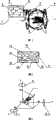
图1为本发明的电磁软跟踪无线供能装置的结构示意图;Fig. 1 is the structural representation of electromagnetic soft tracking wireless energy supply device of the present invention;
图2为本发明的能量接收器的结构示意图;Fig. 2 is a structural schematic diagram of the energy receiver of the present invention;
图3为本发明的电磁分量分解原理图。Fig. 3 is a schematic diagram of electromagnetic component decomposition of the present invention.
具体实施方式Detailed ways
下面结合附图对本发明的实施例作详细说明:本实施例在以本发明技术方案为前提下进行实施,给出了详细的实施方式和具体的操作过程,但本发明的保护范围不限于下述的实施例。The embodiments of the present invention are described in detail below in conjunction with the accompanying drawings: this embodiment is implemented on the premise of the technical solution of the present invention, and detailed implementation methods and specific operating procedures are provided, but the protection scope of the present invention is not limited to the following the described embodiment.
如图1和图2所示,本实施包括:体外无线数据收发器1、体外微处理器2、D/A转换器3、电压源4、Y向发射线圈5、X向发射线圈6、Z向发射线圈8、整流稳压电路9、姿态传感器10、A/D转换器11、钮扣电池12、体内微处理器13、常闭模拟开关14,体内无线数据收发器15、接收线圈16,其连接关系为:体外无线数据收发器1的DIN端口与体外微处理器2的TXD端口相连,体外微处理器2用户端口与D/A转换器3的数据端口相连,电压源4的固定电压输出端与体外无线数据收发器1、体外微处理器2、D/A转换器3相连,电压源4的三个可调的电压输出端分别与Y向发射线圈5、X向发射线圈6、Z向发射线圈8相连,X向发射线圈6、Y向发射线圈5、Z向发射线圈8均由两个线圈串联组成,每两组线圈的轴线互相垂直,在其间组成一个相对均匀的磁场区,钮扣电池12与常闭模拟开关14相连,常闭模拟开关14与体内无线数据收发器15的Vcc端口、体内微处理器13的Vcc端口、A/D转换器11的Vcc端口相连,姿态传感器10的模拟输出端口连接A/D转换器11的模拟输入口,A/D转换器11的数字输出端口与体内微处理器13的用户口端口相连,体内微处理器13的RXD端口和体内无线数据收发器15的DOUT端口相连,体内微处理器13的用户端口P2.0和常闭模拟开关14的控制输入端口相连,接收线圈16的输出端与整流稳压电路9相连,整流稳压电路9的电压输出端口VOUT分别与体内无线数据收发器15的Vcc端口、体内微处理器13的Vcc端口、A/D转换器11的Vcc端口相连。As shown in Figure 1 and Figure 2, this implementation includes: an in vitro
所述整流稳压电路9、钮扣电池12、体内微处理器13、常闭模拟开关14、体内无线数据收发器15、接收线圈16、姿态传感器10、A/D转换器11组成本装置的体内部分的能量接收器7。Described rectifying and stabilizing
所述体外无线数据收发器1、体外微处理器2、D/A转换器3、电压源4、Y向发射线圈5、X向发射线圈6、Z向发射线圈8为本装置的体外装置。The external
所述姿态传感器10,获取接收线圈16轴线的姿态信息,并将姿态信息传递给A/D转换器11。The
所述A/D转换器11,将姿态信息转换为数字量,并将数字量传送给体内微处理器13。The A/
所述体内无线数据收发器15,将体内微处理器13的数字量姿态信息发送至体外。The
所述体外无线数据收发器1,接收体内无线数据收发器15发送的数字量方位角信息。The in vitro
所述体外微处理器2,根据体外无线数据收发器1收到的数字量方位角信息,接收D/A转换器3模拟量姿态信息,计算磁场强度分量计算,并判断出在X轴、Y轴、Z轴三个方向上所要施加的电压值数字量,并将判断结果输出给D/A转换器3电压源4。The in vitro
所述D/A转换器3,将数字量的电压值姿态信息转换为模拟量的电压值姿态信息,该电压用于控制电压源4独立的三个电压输出并将模拟量姿态信息传送给体外微处理器2。The D/
本实施例工作时,能量接收器7固定在器件上,随器件在被检查者体内一起运动,体外安装的X向发射线圈6、Y向发射线圈5、Z向发射线圈8均由两个线圈串联组成,每两组线圈的轴线互相垂直,在其间组成一个相对均匀的磁场区,被检查者置于该区域内。能量接收器7中的纽扣电池12用于在无线供能还不能提供能量时系统的启动和管理,姿态传感器10经过A/D转换器11后将姿态信息转换为数字量传送给体内微处理器13,然后由体内无线数据收发器15发送至体外,在体外部分体外无线数据收发器1检测到数据后再回传一个握手信号,接收线圈16接收体外的三个线圈的电能,X向发射线圈6、Y向发射线圈5、Z向发射线圈8由具有多个独立通道的可调电压源4分别供电,电压源4的电压输出由体外微处理器2和D/A转换器3控制,体外微处理器2分析体外无线数据收发器1接收到的姿态数据,并计算每个线圈需要施加的电压,以合成在体内接收线圈16位置处与接收线圈16轴线平行的磁场,接收线圈16将接收到的电能传输给系统稳压电路9,此时系统稳压电路9和纽扣电池12同时供电,体内微处理器13发出信号到常闭模拟开关14断开纽扣电池12供电,供电模式切换为整流稳压电路9单独供电,并且整流稳压电路9也可以向外部负载供能。When the present embodiment works, the
如图3所示,是X向发射线圈6、Y向发射线圈5、Z向发射线圈8的供电电压的分解原理图。如果满足供能需求的接收线圈16所在处、平行于接收线圈16轴线的磁场强度为B,X向发射线圈6、Y向发射线圈5、Z向发射线圈8产生的磁场分别在X轴、Y轴、Z轴上的磁场强度是主要的,其他方向上很小可以忽略,根据姿态传感器10可以得到接收线圈16与XOY平面夹角为β,与Z轴夹角为γ,在XOY平面内投影与X轴夹角为α,则可以得到应得的X向发射线圈6、Y向发射线圈5、Z向发射线圈8的磁场分量分别为:As shown in FIG. 3 , it is an exploded principle diagram of the power supply voltage of the
Bx=B·cosβ·cosαBx = B·cosβ·cosα
By=B·cosβ·sinαBy =B·cosβ·sinα
Bz=B·sin βBz =B·sin β
最后,体外微处理器2根据螺线管磁场强度和电压的关系反推出X向发射线圈6、Y向发射线圈5、Z向发射线圈8各自应该施加的电压。Finally, the in vitro
本实施例考虑到体内空间狭小,不宜饶制复杂的线圈,因此体内使用简单紧凑的一维接收线圈,体外设计了三个正交发射线圈,利用三线圈产生的磁场合成一个与体内线圈轴线一致的磁场,磁力线最大程度的穿过线圈,从而提高了耦合效率。In this embodiment, considering the narrow space in the body, it is not suitable to make complex coils, so a simple and compact one-dimensional receiving coil is used in the body, and three orthogonal transmitting coils are designed in vitro, and the magnetic field generated by the three coils is used to synthesize a coil that is consistent with the axis of the coil in the body. The magnetic field, the magnetic field lines pass through the coil to the greatest extent, thus improving the coupling efficiency.
Claims (7)
Priority Applications (1)
| Application Number | Priority Date | Filing Date | Title |
|---|---|---|---|
| CN2007100456245ACN101141081B (en) | 2007-09-06 | 2007-09-06 | Electromagnetic soft tracking wireless energy supply device |
Applications Claiming Priority (1)
| Application Number | Priority Date | Filing Date | Title |
|---|---|---|---|
| CN2007100456245ACN101141081B (en) | 2007-09-06 | 2007-09-06 | Electromagnetic soft tracking wireless energy supply device |
Publications (2)
| Publication Number | Publication Date |
|---|---|
| CN101141081A CN101141081A (en) | 2008-03-12 |
| CN101141081Btrue CN101141081B (en) | 2010-08-18 |
Family
ID=39192874
Family Applications (1)
| Application Number | Title | Priority Date | Filing Date |
|---|---|---|---|
| CN2007100456245AExpired - Fee RelatedCN101141081B (en) | 2007-09-06 | 2007-09-06 | Electromagnetic soft tracking wireless energy supply device |
Country Status (1)
| Country | Link |
|---|---|
| CN (1) | CN101141081B (en) |
Families Citing this family (8)
| Publication number | Priority date | Publication date | Assignee | Title |
|---|---|---|---|---|
| KR101228557B1 (en)* | 2010-11-30 | 2013-01-31 | 유한회사 한림포스텍 | Coil resonant coupler for short distance wireless power transmission and apparatus for transmitting power in short distance thereof |
| CN104753184B (en) | 2013-12-31 | 2018-06-05 | 华为技术有限公司 | Transmission of electricity sending method, equipment and system |
| CN104377792B (en)* | 2014-12-01 | 2016-10-05 | 联想(北京)有限公司 | A kind of wireless charging device and method |
| CN104600877A (en)* | 2015-02-13 | 2015-05-06 | 哈尔滨工业大学 | Wireless power transmission device with sidesway adaptability and rotation adaptability |
| JP6991143B2 (en)* | 2015-09-11 | 2022-01-12 | ヤンク テクノロジーズ,インコーポレーテッド | Wireless charging platform via 3D phased coil array |
| US11183881B2 (en) | 2015-09-11 | 2021-11-23 | Yank Technologies, Inc. | Injection molding electroplating for three-dimensional antennas |
| CN109462293A (en)* | 2018-09-27 | 2019-03-12 | 深圳市华禹无线供电技术有限公司 | A kind of receiving coil location determining method of omnidirection radio energy transmission system |
| CN109617254B (en)* | 2018-12-17 | 2022-07-15 | 中国科学技术大学 | Wireless energy transmission system and method based on magnetic field focusing technology |
Citations (3)
| Publication number | Priority date | Publication date | Assignee | Title |
|---|---|---|---|---|
| US6366817B1 (en)* | 1999-05-03 | 2002-04-02 | Abiomed, Inc. | Electromagnetic field source device with detection of position of secondary coil in relation to multiple primary coils |
| CN2682716Y (en)* | 2004-03-25 | 2005-03-02 | 北京交通大学 | A non-contact charger for medical apparatus inside human body |
| CN1874048A (en)* | 2006-04-28 | 2006-12-06 | 清华大学 | Wireless charging device through skin in use for implantation type medical treatment instrument |
- 2007
- 2007-09-06CNCN2007100456245Apatent/CN101141081B/ennot_activeExpired - Fee Related
Patent Citations (3)
| Publication number | Priority date | Publication date | Assignee | Title |
|---|---|---|---|---|
| US6366817B1 (en)* | 1999-05-03 | 2002-04-02 | Abiomed, Inc. | Electromagnetic field source device with detection of position of secondary coil in relation to multiple primary coils |
| CN2682716Y (en)* | 2004-03-25 | 2005-03-02 | 北京交通大学 | A non-contact charger for medical apparatus inside human body |
| CN1874048A (en)* | 2006-04-28 | 2006-12-06 | 清华大学 | Wireless charging device through skin in use for implantation type medical treatment instrument |
Non-Patent Citations (1)
| Title |
|---|
| 马官营,颜国正,于莲芝等.人体消化道内微机电系统线圈耦合系数分析.北京生物医学工程25 5.2006,25(5),486-489.* |
Also Published As
| Publication number | Publication date |
|---|---|
| CN101141081A (en) | 2008-03-12 |
Similar Documents
| Publication | Publication Date | Title |
|---|---|---|
| CN101141081B (en) | Electromagnetic soft tracking wireless energy supply device | |
| Ma et al. | Enabling deep-tissue networking for miniature medical devices | |
| CN107924758B (en) | Cable unit for connecting devices to enable wireless exchange of data and/or power between devices | |
| Puers et al. | Wireless power and data transmission strategies for next-generation capsule endoscopes | |
| CN107920752B (en) | Battery modules for wireless exchange of data and power | |
| EP3345280B1 (en) | Device for wireless transmission of data and/or power | |
| Carta et al. | A wireless power supply system for robotic capsular endoscopes | |
| US20180262236A1 (en) | Connector and device for wireless transmission of data and power | |
| EP3345200B1 (en) | Stackable connector and device for wireless transmission of power | |
| CN103356150A (en) | Capsule endoscope magnetic field driving system under orientation tracking guide | |
| TWI235523B (en) | A radio transmitter and receiver of an implantable medical device | |
| US9973031B2 (en) | Orientation-independent wireless charging | |
| Zhang et al. | Transmitter adaptation and wireless power control for capsule endoscopy | |
| Mariello et al. | Wireless Power and Data Transfer Technologies for flexible bionic and Bioelectronic interfaces: materials and applications | |
| CN201323473Y (en) | Internal micro electro-mechanical system wireless energy transmission device | |
| Wang et al. | A body sensor networks development platform for pervasive healthcare | |
| CN115067853A (en) | Wireless charging system and method for capsule endoscope and storage medium | |
| CN102122846B (en) | Wireless energy supply device for implantable wireless telemetry | |
| Zhang et al. | Wireless power delivery for wearable sensors and implants in body sensor networks | |
| CN206910316U (en) | It is a kind of can swallowable capsule endoscope wireless charging system | |
| Guozheng et al. | Design of battery-less and real-time telemetry system for gastrointestinal applications | |
| Mohammed et al. | Charging Wearable Devices Through Natural Interactions with Instrumented Everyday Objects | |
| CN209474652U (en) | Portable probe and compuscan | |
| Mirbozorgi et al. | Multicoil resonance-based parallel array for smart wireless power delivery | |
| Yuste Muñoz | WIRELESS ENERGY TRANSFER AND WIRELESS COMMUNICATION FOR IN-BODY SENSORS |
Legal Events
| Date | Code | Title | Description |
|---|---|---|---|
| C06 | Publication | ||
| PB01 | Publication | ||
| C10 | Entry into substantive examination | ||
| SE01 | Entry into force of request for substantive examination | ||
| C14 | Grant of patent or utility model | ||
| GR01 | Patent grant | ||
| CF01 | Termination of patent right due to non-payment of annual fee | Granted publication date:20100818 Termination date:20160906 | |
| CF01 | Termination of patent right due to non-payment of annual fee |