CN101136553B - Emergent charging apparatus - Google Patents
Emergent charging apparatusDownload PDFInfo
- Publication number
- CN101136553B CN101136553BCN2006100624477ACN200610062447ACN101136553BCN 101136553 BCN101136553 BCN 101136553BCN 2006100624477 ACN2006100624477 ACN 2006100624477ACN 200610062447 ACN200610062447 ACN 200610062447ACN 101136553 BCN101136553 BCN 101136553B
- Authority
- CN
- China
- Prior art keywords
- circuit
- charging
- power
- plug
- audio
- Prior art date
- Legal status (The legal status is an assumption and is not a legal conclusion. Google has not performed a legal analysis and makes no representation as to the accuracy of the status listed.)
- Expired - Fee Related
Links
Images
Classifications
- H—ELECTRICITY
- H02—GENERATION; CONVERSION OR DISTRIBUTION OF ELECTRIC POWER
- H02J—CIRCUIT ARRANGEMENTS OR SYSTEMS FOR SUPPLYING OR DISTRIBUTING ELECTRIC POWER; SYSTEMS FOR STORING ELECTRIC ENERGY
- H02J7/00—Circuit arrangements for charging or depolarising batteries or for supplying loads from batteries
Landscapes
- Engineering & Computer Science (AREA)
- Power Engineering (AREA)
- Charge And Discharge Circuits For Batteries Or The Like (AREA)
- Secondary Cells (AREA)
Abstract
Translated fromChinese
Description
Translated fromChinese技术领域technical field
本发明涉及一种充电装置,特别涉及一应急充电装置。 The invention relates to a charging device, in particular to an emergency charging device. the
背景技术Background technique
目前,市场上销售的充电器,绝大部分是从交流电源获得充电电量;或者,使用USB(Universal Serial Bus;通用串行总线)接口为电子装置充电。由交流电源获得充电电量进行充电,必须有交流电源;而通过USB接口充电,必须有可提供USB充电的充电源,如计算机。然而,人们在使用便携式电子装置(例如手机、MP3、MD、CD等音频播放装置)时,常常会遇到不具备前述的两种充电方式条件的情况,例如,在乘坐长途客车等交通工具时,在野外露营时携带便携式电子装置,便携式电子装置的充电电池的电量通常会消耗完毕,而找不到交流电源及USB充电的充电源而无法补充电量,又无法从其他同类电子装置或其他音频播放设备获取一定的电量时,该电子装置无法继续工作,给用户带来不便。 At present, most of the chargers sold on the market obtain charging power from an AC power source; or, use a USB (Universal Serial Bus; Universal Serial Bus) interface to charge electronic devices. To charge by obtaining charging power from an AC power source, there must be an AC power source; and to charge through a USB interface, there must be a charging source that can provide USB charging, such as a computer. However, when people use portable electronic devices (such as audio playback devices such as mobile phones, MP3, MD, CD, etc.), they often encounter situations that do not possess the aforementioned two charging methods. , when carrying portable electronic devices while camping in the wild, the power of the rechargeable battery of the portable electronic device is usually exhausted, and the charging source of AC power and USB charging cannot be found to replenish the power, and it is impossible to use it from other similar electronic devices or other audio devices. When the playback device obtains a certain amount of power, the electronic device cannot continue to work, which brings inconvenience to the user. the
发明内容Contents of the invention
有鉴于此,有必要提供一种应急的充电装置,使待充电的电子装置从同类电子装置或其他音频播放设备获取一定的电量。 In view of this, it is necessary to provide an emergency charging device, so that the electronic device to be charged can obtain a certain amount of power from similar electronic devices or other audio playback devices. the
该应急充电装置,包括:一充电电路、一充电插头,所述充电插头连接一待充电的电子装置。所述充电装置还包括一音频插头、一转换开关及一耳机,所述音频插头连接一音频播放装置,所述转换开关用于转换所述耳机或充电电路与所述音频插头的电连接;当所述转换开关电连接所述耳机与音频插头时,耳机播放所述音频播放装置输出的音频信号;当所述转换开关电连接所述充电电路与音频插头时,充电电路利用该音频播放装置输出的电量经所述充电插头为所述待充电电子装置充电。 The emergency charging device includes: a charging circuit and a charging plug, and the charging plug is connected to an electronic device to be charged. The charging device also includes an audio plug, a switch and an earphone, the audio plug is connected to an audio playback device, and the switch is used to switch the electrical connection between the earphone or the charging circuit and the audio plug; When the transfer switch is electrically connected to the earphone and the audio plug, the earphone plays the audio signal output by the audio playback device; when the transfer switch is electrically connected to the charging circuit and the audio plug, the charging circuit uses the audio playback device to output The amount of electricity is used to charge the electronic device to be charged through the charging plug. the
该应急充电装置,包括一充电电路、一充电插头,所述充电插头连接一电子装置,所述充电装置还包括一音频插头,所述音频插头连接一音频播放 装置,所述充电电路包括一转换电路、一电量积分电路、一电量释放电路、一检测电路与一控制单元,所述转换电路将音频播放装置输出的音频交流电压进行升压和整流成直流电;所述电量积分电路积分所述直流电;所述电量释放电路释放电量积分电路累积的电量经过所述充电插头给所述电子装置充电;所述的检测电路检测电量积分电路积累的电压、电量并输出一检测值至所述控制单元;所述控制单元将检测值与预设的电压、电量值比较,并输出一控制信号至所述电量释放电路,该控制信号用于控制电量释放电路的工作状态。 The emergency charging device includes a charging circuit and a charging plug, the charging plug is connected to an electronic device, the charging device also includes an audio plug, the audio plug is connected to an audio playback device, and the charging circuit includes a conversion circuit, a power integration circuit, a power release circuit, a detection circuit and a control unit, the conversion circuit boosts and rectifies the audio AC voltage output by the audio playback device into direct current; the power integration circuit integrates the direct current The power release circuit releases the power accumulated by the power integration circuit to charge the electronic device through the charging plug; the detection circuit detects the voltage and power accumulated by the power integration circuit and outputs a detection value to the control unit; The control unit compares the detected value with the preset voltage and power value, and outputs a control signal to the power discharge circuit, and the control signal is used to control the working state of the power discharge circuit. the
本发明之优点在于,所述的应急充电装置,既可以为待充电的电子装置从其它具有音频接口的音频播放装置获得电量;同时,该应急充电装置,又可以用作耳机,播放音频信号。 The advantage of the present invention is that the emergency charging device can obtain electricity for the electronic device to be charged from other audio playback devices with audio interfaces; at the same time, the emergency charging device can also be used as an earphone to play audio signals. the
附图说明Description of drawings
图1为本发明应急充电装置第一实施方式硬体架构图。 Fig. 1 is a hardware architecture diagram of the first embodiment of the emergency charging device of the present invention. the
图2为图1所示应急充电装置第一实施方式的细化架构图。 Fig. 2 is a detailed structural diagram of the first embodiment of the emergency charging device shown in Fig. 1 . the
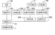
图3为本发明应急充电装置第二实施方式细化架构图。 Fig. 3 is a detailed structure diagram of the second embodiment of the emergency charging device of the present invention. the
具体实施方式Detailed ways
请参阅图1,为应急充电装置(下简称为“充电装置”)第一实施方式的硬体架构图。所述充电装置包括一音频插头10、一转换开关20、一充电电路30、一充电插头40及一耳机50。所述的音频插头10用于插接一音频播放装置1,从所述音频播放装置1的音频接口获得音频信号或电量;所述的充电插头40,用于插接于待充电的电子装置2,为所述电子装置2提供充电电量,所述的耳机50,用于播放所获得的音频信号。所述的转换开关20为一手动开关,用于选择电连接所述的耳机50或充电电路30至音频插头10。当转换开关20将耳机50连接于音频插头10时,音频播放装置输出的音频信号由耳机50播放;当转换开关20将充电电路30连接于音频插头时,音频播放装置1通过音频插头10输出的电量经充电电路30及充电插头40为电子装置2充电。 Please refer to FIG. 1 , which is a hardware architecture diagram of a first embodiment of an emergency charging device (hereinafter referred to as "charging device"). The charging device includes an
请一并参阅图2,为应急充电装置的细化架构图。在该细化架构图中, 所述充电电路30包括:一转换电路301、一电量积分电路302、一电量释放电路303、一检测电路304及一控制单元305。所述的转换电路301连接于转换开关20,用于将音频播放装置1输出的电量升压并转化为直流电;所述的电量积分电路302,用于将所述转换电路301转换后的直流微电量进行积累;所述检测电路304,用于检测电量积分电路302积累的电压及电量,并输出检测值;所述控制单元305接收所述检测值,将所述检测值与存储于控制单元305内部的预设电压值、电量值进行比较,并输出一控制信号,所述的控制信号输入至所述的电量释放电路303,控制电量释放电路303的工作状态,所述控制信号包括一电量释放信号和一电量禁止释放信号。例如,若检测电路304检测的电压值、电量值小于控制单元305预设的电压值、电量值时,控制单元305输出一电量禁止释放信号控制电量释放电路303禁止为电子装置2充电;若检测电路304检测的电压值、电量值大于或等于控制单元305内预设的电压值、电量值时,控制单元305输出一电量释放信号,控制电量释放电路303经由充电插头40为电子装置2充电。 Please also refer to FIG. 2 , which is a detailed structure diagram of the emergency charging device. In the detailed architecture diagram, the
因此,当转换开关20将耳机50连接于音频插头10时,音频播放装置1输出的音频经音频插头10由耳机50播放,此时上述应急充电装置用作耳机使用。当转换开关20将充电电路30和充电插头40连接于音频插头10时,音频播放装置1输出的电量经充电电路30及充电插头40为电子装置充电,此时,应急充电装置用作充电器,给电子装置2应急充电。 Therefore, when the
请参阅图3,为本发明应急充电装置的第二实施方式细化架构图。在该细化架构图中,所述充电装置包括一音频插头10、一充电电路30、一充电插头40。所述的音频插头10用于插接一音频播放装置1,从所述音频播放装置1的音频接口获得音频信号或电量;所述的充电插头40,用于插接于待充电的电子装置2,为所述电子装置2提供充电电量。所述充电电路30包括:一转换电路301、一电量积分电路302、一电量释放电路303、一检测电路304及一控制单元305。所述的转换电路301连接于音频插头10,用于将音频播放装置输出的电量升压并转化为直流电;所述的电量积分电路302,用于将所述转换电路301转换后的直流微电量进行积累;所述检测电路304,用于检测电量积分电路302积累的电压及电量,并输出检测值;所述控制单元305接收所述检测值,将所述检测值与存储于控制单元305内部的预设电压值、 电量值进行比较,并输出一控制信号,所述的控制信号输入至所述的电量释放电路303,控制电量释放电路303的工作状态,所述控制信号包括一电量释放信号和一电量禁止释放信号。例如,若检测电路304检测的电压值、电量值小于控制单元305预设的电压值、电量值时,控制单元305输出一电量禁止释放信号控制电量释放电路303禁止为电子装置2充电;若检测电路304检测的电压值、电量值大于或等于控制单元305内预设的电压值、电量值时,控制单元305输出一电量释放信号,控制电量释放电路303经由充电插头40为电子装置2充电。 Please refer to FIG. 3 , which is a detailed structure diagram of the second embodiment of the emergency charging device of the present invention. In the detailed architecture diagram, the charging device includes an
Claims (9)
Translated fromChinesePriority Applications (2)
| Application Number | Priority Date | Filing Date | Title |
|---|---|---|---|
| CN2006100624477ACN101136553B (en) | 2006-09-01 | 2006-09-01 | Emergent charging apparatus |
| US11/744,892US7633270B2 (en) | 2006-09-01 | 2007-05-07 | Charger |
Applications Claiming Priority (1)
| Application Number | Priority Date | Filing Date | Title |
|---|---|---|---|
| CN2006100624477ACN101136553B (en) | 2006-09-01 | 2006-09-01 | Emergent charging apparatus |
Publications (2)
| Publication Number | Publication Date |
|---|---|
| CN101136553A CN101136553A (en) | 2008-03-05 |
| CN101136553Btrue CN101136553B (en) | 2011-12-21 |
Family
ID=39150547
Family Applications (1)
| Application Number | Title | Priority Date | Filing Date |
|---|---|---|---|
| CN2006100624477AExpired - Fee RelatedCN101136553B (en) | 2006-09-01 | 2006-09-01 | Emergent charging apparatus |
Country Status (2)
| Country | Link |
|---|---|
| US (1) | US7633270B2 (en) |
| CN (1) | CN101136553B (en) |
Families Citing this family (23)
| Publication number | Priority date | Publication date | Assignee | Title |
|---|---|---|---|---|
| US20160345631A1 (en) | 2005-07-19 | 2016-12-01 | James Monsees | Portable devices for generating an inhalable vapor |
| KR100765790B1 (en)* | 2006-06-30 | 2007-10-12 | 삼성전자주식회사 | Variable power supply and method for mobile devices |
| WO2010034337A1 (en)* | 2008-09-23 | 2010-04-01 | Phonak Ag | Hearing system and method for operating such a system |
| CN102364515B (en)* | 2011-10-24 | 2014-12-17 | 深圳盒子支付信息技术有限公司 | Payment circuit of mobile payment terminal |
| KR101832832B1 (en) | 2011-12-26 | 2018-02-28 | 삼성전자주식회사 | Apparatus and method for charging battery pack in portable terminal |
| CN103855437A (en)* | 2012-11-28 | 2014-06-11 | 北京旋极信息技术股份有限公司 | Method and apparatus for charging electronic signature device |
| US10279934B2 (en) | 2013-03-15 | 2019-05-07 | Juul Labs, Inc. | Fillable vaporizer cartridge and method of filling |
| US10076139B2 (en) | 2013-12-23 | 2018-09-18 | Juul Labs, Inc. | Vaporizer apparatus |
| USD825102S1 (en) | 2016-07-28 | 2018-08-07 | Juul Labs, Inc. | Vaporizer device with cartridge |
| US20160366947A1 (en) | 2013-12-23 | 2016-12-22 | James Monsees | Vaporizer apparatus |
| US10159282B2 (en) | 2013-12-23 | 2018-12-25 | Juul Labs, Inc. | Cartridge for use with a vaporizer device |
| USD842536S1 (en) | 2016-07-28 | 2019-03-05 | Juul Labs, Inc. | Vaporizer cartridge |
| DE202014011260U1 (en) | 2013-12-23 | 2018-11-13 | Juul Labs Uk Holdco Limited | Systems for an evaporation device |
| US10058129B2 (en) | 2013-12-23 | 2018-08-28 | Juul Labs, Inc. | Vaporization device systems and methods |
| MX394125B (en) | 2014-12-05 | 2025-03-24 | Juul Labs Inc | CALIBRATED DOSE CONTROL |
| EP3413960B1 (en) | 2016-02-11 | 2021-03-31 | Juul Labs, Inc. | Fillable vaporizer cartridge and method of filling |
| CO2018009342A2 (en) | 2016-02-11 | 2018-09-20 | Juul Labs Inc | Secure fixing cartridges for vaporizing devices |
| US10405582B2 (en) | 2016-03-10 | 2019-09-10 | Pax Labs, Inc. | Vaporization device with lip sensing |
| CN205847496U (en)* | 2016-06-08 | 2016-12-28 | 中兴通讯股份有限公司 | A kind of head circuit structure and terminal unit |
| USD849996S1 (en) | 2016-06-16 | 2019-05-28 | Pax Labs, Inc. | Vaporizer cartridge |
| USD836541S1 (en) | 2016-06-23 | 2018-12-25 | Pax Labs, Inc. | Charging device |
| USD851830S1 (en) | 2016-06-23 | 2019-06-18 | Pax Labs, Inc. | Combined vaporizer tamp and pick tool |
| USD887632S1 (en) | 2017-09-14 | 2020-06-16 | Pax Labs, Inc. | Vaporizer cartridge |
Citations (4)
| Publication number | Priority date | Publication date | Assignee | Title |
|---|---|---|---|---|
| CN1406039A (en)* | 2001-09-12 | 2003-03-26 | Lg电子株式会社 | Apparatus and method for charging from one mobile apparatus to an other mobile apparatus |
| US6552512B1 (en)* | 2001-07-10 | 2003-04-22 | Scott C. Harris | Portable device charger based on audio energy power |
| CN1641923A (en)* | 2004-01-09 | 2005-07-20 | 顺德市顺达电脑厂有限公司 | Mobile phone cell charging device |
| CN2775980Y (en)* | 2005-01-10 | 2006-04-26 | 广州七喜电脑股份有限公司 | Multimedia stere active sound speaker |
Family Cites Families (3)
| Publication number | Priority date | Publication date | Assignee | Title |
|---|---|---|---|---|
| US5479479A (en)* | 1991-10-19 | 1995-12-26 | Cell Port Labs, Inc. | Method and apparatus for transmission of and receiving signals having digital information using an air link |
| JP2003079061A (en)* | 2001-08-30 | 2003-03-14 | Yamaha Corp | Charger for mobile audio device and audio system |
| US20050116684A1 (en)* | 2003-11-27 | 2005-06-02 | Kim Ju-Young | Portable charger for mobile phones |
- 2006
- 2006-09-01CNCN2006100624477Apatent/CN101136553B/ennot_activeExpired - Fee Related
- 2007
- 2007-05-07USUS11/744,892patent/US7633270B2/ennot_activeExpired - Fee Related
Patent Citations (4)
| Publication number | Priority date | Publication date | Assignee | Title |
|---|---|---|---|---|
| US6552512B1 (en)* | 2001-07-10 | 2003-04-22 | Scott C. Harris | Portable device charger based on audio energy power |
| CN1406039A (en)* | 2001-09-12 | 2003-03-26 | Lg电子株式会社 | Apparatus and method for charging from one mobile apparatus to an other mobile apparatus |
| CN1641923A (en)* | 2004-01-09 | 2005-07-20 | 顺德市顺达电脑厂有限公司 | Mobile phone cell charging device |
| CN2775980Y (en)* | 2005-01-10 | 2006-04-26 | 广州七喜电脑股份有限公司 | Multimedia stere active sound speaker |
Also Published As
| Publication number | Publication date |
|---|---|
| CN101136553A (en) | 2008-03-05 |
| US20080054854A1 (en) | 2008-03-06 |
| US7633270B2 (en) | 2009-12-15 |
Similar Documents
| Publication | Publication Date | Title |
|---|---|---|
| CN101136553B (en) | Emergent charging apparatus | |
| RU2587159C2 (en) | Mobile terminal and interface connection method therefor | |
| JP3161472U (en) | Embedded charging socket | |
| US20090309542A1 (en) | Multi-input charger | |
| TWI462426B (en) | Mobile device and method of charging | |
| CN102299532B (en) | Charging device | |
| CN102347552B (en) | Outlet combo with portable charger | |
| CN114243871B (en) | Charging and discharging circuit, electronic equipment and electronic system | |
| CN203377652U (en) | A mobile power source with a sound prompt function | |
| GB2344229A (en) | Battery charger | |
| CN211579139U (en) | Two unification charging wires and charger | |
| US8583946B2 (en) | External device charging while notebook is off | |
| US20120286731A1 (en) | Battery charger | |
| US20100001691A1 (en) | Battery assembly | |
| US20110101925A1 (en) | Feedback-adjustable charging system and method thereof | |
| CN105827010A (en) | A power supply system for audio equipment | |
| US20130300365A1 (en) | Intelligent wall-type charger | |
| CN103532173A (en) | Mobile equipment and charging system with the same | |
| TW200814488A (en) | Lash-up charger | |
| CN203522282U (en) | Mobile power source with storage device | |
| CN205647000U (en) | Audio equipment power supply system | |
| CN202205134U (en) | Plate computer | |
| CN202798056U (en) | Multifunctional charger | |
| TW201004097A (en) | Portable power supply device | |
| CN203180572U (en) | Intelligent charger with audio/video playing function |
Legal Events
| Date | Code | Title | Description |
|---|---|---|---|
| C06 | Publication | ||
| PB01 | Publication | ||
| C10 | Entry into substantive examination | ||
| SE01 | Entry into force of request for substantive examination | ||
| C14 | Grant of patent or utility model | ||
| GR01 | Patent grant | ||
| CF01 | Termination of patent right due to non-payment of annual fee | ||
| CF01 | Termination of patent right due to non-payment of annual fee | Granted publication date:20111221 Termination date:20190901 |