CN101132861A - Electrostatic coating device - Google Patents
Electrostatic coating deviceDownload PDFInfo
- Publication number
- CN101132861A CN101132861ACNA2006800068864ACN200680006886ACN101132861ACN 101132861 ACN101132861 ACN 101132861ACN A2006800068864 ACNA2006800068864 ACN A2006800068864ACN 200680006886 ACN200680006886 ACN 200680006886ACN 101132861 ACN101132861 ACN 101132861A
- Authority
- CN
- China
- Prior art keywords
- mentioned
- cover
- neck
- side cover
- paint
- Prior art date
- Legal status (The legal status is an assumption and is not a legal conclusion. Google has not performed a legal analysis and makes no representation as to the accuracy of the status listed.)
- Granted
Links
Images


Classifications
- B—PERFORMING OPERATIONS; TRANSPORTING
- B05—SPRAYING OR ATOMISING IN GENERAL; APPLYING FLUENT MATERIALS TO SURFACES, IN GENERAL
- B05B—SPRAYING APPARATUS; ATOMISING APPARATUS; NOZZLES
- B05B5/00—Electrostatic spraying apparatus; Spraying apparatus with means for charging the spray electrically; Apparatus for spraying liquids or other fluent materials by other electric means
- B05B5/025—Discharge apparatus, e.g. electrostatic spray guns
- B05B5/053—Arrangements for supplying power, e.g. charging power
- B05B5/0533—Electrodes specially adapted therefor; Arrangements of electrodes
- B—PERFORMING OPERATIONS; TRANSPORTING
- B05—SPRAYING OR ATOMISING IN GENERAL; APPLYING FLUENT MATERIALS TO SURFACES, IN GENERAL
- B05B—SPRAYING APPARATUS; ATOMISING APPARATUS; NOZZLES
- B05B15/00—Details of spraying plant or spraying apparatus not otherwise provided for; Accessories
- B05B15/50—Arrangements for cleaning; Arrangements for preventing deposits, drying-out or blockage; Arrangements for detecting improper discharge caused by the presence of foreign matter
- B—PERFORMING OPERATIONS; TRANSPORTING
- B05—SPRAYING OR ATOMISING IN GENERAL; APPLYING FLUENT MATERIALS TO SURFACES, IN GENERAL
- B05B—SPRAYING APPARATUS; ATOMISING APPARATUS; NOZZLES
- B05B5/00—Electrostatic spraying apparatus; Spraying apparatus with means for charging the spray electrically; Apparatus for spraying liquids or other fluent materials by other electric means
- B05B5/025—Discharge apparatus, e.g. electrostatic spray guns
- B05B5/04—Discharge apparatus, e.g. electrostatic spray guns characterised by having rotary outlet or deflecting elements, i.e. spraying being also effected by centrifugal forces
- B05B5/0415—Driving means; Parts thereof, e.g. turbine, shaft, bearings
- B—PERFORMING OPERATIONS; TRANSPORTING
- B05—SPRAYING OR ATOMISING IN GENERAL; APPLYING FLUENT MATERIALS TO SURFACES, IN GENERAL
- B05B—SPRAYING APPARATUS; ATOMISING APPARATUS; NOZZLES
- B05B5/00—Electrostatic spraying apparatus; Spraying apparatus with means for charging the spray electrically; Apparatus for spraying liquids or other fluent materials by other electric means
- B05B5/025—Discharge apparatus, e.g. electrostatic spray guns
- B05B5/04—Discharge apparatus, e.g. electrostatic spray guns characterised by having rotary outlet or deflecting elements, i.e. spraying being also effected by centrifugal forces
- B05B5/0426—Means for supplying shaping gas
Landscapes
- Electrostatic Spraying Apparatus (AREA)
Abstract
Description
Translated fromChinese技术领域technical field
本发明涉及做成在施加了高电压的状态下喷雾涂料的静电涂敷装置。The present invention relates to an electrostatic coating device configured to spray paint while applying a high voltage.
背景技术Background technique
一般来讲,作为静电涂敷装置已知有例如具备:由气动马达和旋转雾化头构成的喷雾器;由绝缘材料形成并保持该喷雾器的气动马达的壳体部件;包覆该壳体部件的外表面而设置成筒状的罩部件;以及使用外部电极使从喷雾器的旋转雾化头喷雾出的涂料粒子带负的高电压的高电压发生器(例如,参照日本特开2001-113207号公报)的装置。In general, as an electrostatic coating device, for example, an atomizer composed of an air motor and a rotary atomizing head is known; a casing part of the air motor that is formed of an insulating material and holds the atomizer; The outer surface is provided with a cylindrical cover member; and a high-voltage generator (for example, refer to Japanese Patent Application Laid-Open No. )installation.
在这种现有技术的静电涂敷装置中,在施加了负的高电压的外部电极和处在接地电位的旋转雾化头之间以及外部电极和被涂物之间,分别形成由电力线所引起的静电场区域。另外,在外部电极的前端附近形成负离子化集中区域。In this prior art electrostatic coating device, between the external electrode applied with the negative high voltage and the rotary atomizing head at the ground potential, and between the external electrode and the object to be coated, a circuit formed by the electric force line is respectively formed. The induced electrostatic field area. In addition, a negative ionization concentrated region is formed near the tip of the external electrode.
在该状态下,若使用高速旋转的旋转雾化头进行涂料喷雾,则从旋转雾化头呈雾状喷出的涂料粒子随通过离子化集中区域而带负的高电压,成为带电涂料粒子。由此,带电涂料粒子朝向接地的被涂物飞行,涂敷附着在该被涂物的表面上。In this state, if a high-speed rotating rotary atomizing head is used for paint spraying, the paint particles sprayed from the rotary atomizing head in mist form will be charged with a high negative voltage as they pass through the ionization concentration area and become charged paint particles. As a result, the charged paint particles fly toward the grounded object to be coated, and the coating adheres to the surface of the object to be coated.
然而,在日本特开2001-113207号公报公开的静电涂敷装置中,罩部件的外表面带所放电的负离子的负极性电。因此,处于负的相同极性的带电涂料粒子和罩部件彼此排斥,从而防止涂料粒子附着在罩部件的外表面上。另外,罩部件等通过使用绝缘材料形成,防止其外表面所带高电压的电荷向接地电位一侧漏泄。However, in the electrostatic coating device disclosed in Japanese Patent Application Laid-Open No. 2001-113207, the outer surface of the cover member is charged with the negative polarity of the discharged negative ions. Therefore, the charged paint particles and the cover member, which are in negative same polarity, repel each other, thereby preventing the paint particles from adhering to the outer surface of the cover member. In addition, the cover member and the like are formed using an insulating material to prevent leakage of high-voltage charges charged on the outer surface to the ground potential side.
但实际上,随着继续进行静电涂敷,涂料粒子渐渐附着到罩部件的外表面上,成为附着涂料。因此,存在因该附着涂料使得罩部件的外表面的绝缘度下降的问题。并且,一旦罩部件的绝缘度下降,则涂料附着急剧地进行。因此,在现有技术中,为了去除所附着的涂料,不得不频繁地中断涂敷作业。However, as the electrostatic coating is continued, the paint particles are gradually attached to the outer surface of the cover member to form adhering paint. Therefore, there is a problem that the degree of insulation of the outer surface of the cover member decreases due to the adhered paint. In addition, when the degree of insulation of the cover member decreases, paint adhesion rapidly progresses. Therefore, in the prior art, in order to remove the adhered paint, the coating operation had to be frequently interrupted.
另外,在日本特开2001-113207号公报公开的静电涂敷装置中,通过在罩部件的外表面上涂敷憎水性涂料来防止涂料粒子的附着。但由于在涂敷装置中,伴随涂敷作业结束时清洗涂敷装置的外表面,憎水性涂料的膜厚渐渐变薄,因此,有必要定期地重新涂敷憎水性涂料。另外,由于憎水性涂料的品质不稳定,因此,也存在成品率较低,而且涂层形成作业本身的成本也高的问题。In addition, in the electrostatic coating device disclosed in JP-A-2001-113207, adhesion of paint particles is prevented by applying a hydrophobic paint to the outer surface of the cover member. However, in the coating device, the film thickness of the hydrophobic paint gradually becomes thinner as the outer surface of the coating device is cleaned at the end of the coating operation. Therefore, it is necessary to periodically reapply the hydrophobic paint. In addition, since the quality of the water-repellent paint is unstable, there are also problems in that the yield is low, and the cost of the coating layer forming operation itself is also high.
发明内容Contents of the invention
本发明就是鉴于上述现有技术的问题而完成的,本发明其目的在于提供使罩部件的外表面稳定地带高电压,并能够防止涂料粒子附着的静电涂敷装置。The present invention has been made in view of the problems of the prior art described above, and an object of the present invention is to provide an electrostatic coating device capable of stably applying a high voltage to the outer surface of a cover member and preventing adhesion of paint particles.
(1)为了解决上述课题,本发明的静电涂敷装置,包括:将所供给的涂料向被涂物呈雾状喷出的涂料喷雾单元;由绝缘材料形成并保持该涂料喷雾单元的壳体部件;由绝缘材料形成并包覆该壳体部件的外表面而设置成筒状的罩部件;以及使从上述涂料喷雾单元呈雾状喷出的涂料粒子带高电压,并使带电涂料粒子涂敷附着在被涂物上的高电压施加单元;其特征是,做成在上述壳体部件和罩部件之间,沿着这些壳体部件和罩部件互相面对的部位的整个面设置空间的结构。(1) In order to solve the above-mentioned problems, the electrostatic coating device of the present invention includes: a paint spray unit that sprays the supplied paint to the object to be coated; a housing that is formed of an insulating material and holds the paint spray unit A component; a cover member formed of an insulating material and covering the outer surface of the casing member and provided in a cylindrical shape; A high-voltage application unit attached to an object to be coated; characterized in that, between the above-mentioned case member and the cover member, a space is provided along the entire surface of the portion where the case member and the cover member face each other structure.
一般来讲,与空气相比,由绝缘材料构成的壳体部件其电阻较小。于是,由于做成在壳体部件和罩部件之间,沿着这些壳体部件和罩部件互相面对的部位的整个面设置空间的结构,因此,能够减少电阻比空气低的壳体部件与罩部件接触的部位。其结果,由于能够减少带高电压的罩部件的外表面的电荷通过壳体部件漏泄,因而能够保持罩部件的带电状态,能够防止带电涂料粒子的附着。In general, housing parts made of insulating material have a lower electrical resistance than air. Therefore, since a space is provided between the case member and the cover member along the entire surface of the portion where the case member and the cover member face each other, it is possible to reduce the number of cases between the case member and the case member whose resistance is lower than that of air. The part where the cover parts come into contact. As a result, leakage of charge on the outer surface of the high-voltage cover member through the case member can be reduced, so that the charged state of the cover member can be maintained, and adhesion of charged paint particles can be prevented.
(2)在本发明中,上述罩部件使用由氟系树脂材料构成的氟系树脂膜构件或由聚乙烯树脂构成的聚乙烯树脂膜构件形成。(2) In the present invention, the cover member is formed using a fluorine-based resin film member made of a fluorine-based resin material or a polyethylene resin film member made of a polyethylene resin.
由此,使用例如像四氟乙烯等的氟系树脂膜构件或聚乙烯树脂膜构件那样的具有憎水性的材料能够形成罩部件,通过憎水作用能够防止带电涂料粒子附着在罩部件上。另外,通过使氟系树脂膜构件或聚乙烯树脂膜构件带电,能够对带电涂料粒子产生相斥力。再有,由于氟系树脂膜构件及聚乙烯树脂膜构件其吸湿性较低而体积电阻系数较大,因此,它们所带的电荷不易漏泄。因此,能够稳定地保持罩部件的带电状态。Thus, the cover member can be formed using a water-repellent material such as a fluororesin film member such as tetrafluoroethylene or a polyethylene resin film member, and the water-repellent effect can prevent charged paint particles from adhering to the cover member. In addition, by charging the fluorine-based resin film member or the polyethylene resin film member, a repulsive force can be generated for the charged paint particles. Furthermore, since the fluorine-based resin film member and the polyethylene resin film member have low hygroscopicity and high volume resistivity, the charges carried by them are less likely to leak. Therefore, the charged state of the cover member can be stably maintained.
(3)在本发明中,上述罩部件使用在具有绝缘性的两片绝缘膜之间夹着具有半导电性的半导电膜的层叠膜构件形成。(3) In the present invention, the cover member is formed using a laminated film member in which a semiconductive semiconductive film is sandwiched between two insulating insulating films.
此时,由于电荷能在半导电膜中移动,因此,半导电膜沿着整体大致处在同电位。受该半导电膜的稳定电位的影响,能够得到使包覆半导电膜表面的绝缘膜的表面更均匀地带电的效果。At this time, since charges can move in the semiconductive film, the semiconductive film is substantially at the same potential along the entirety. Affected by the stable potential of the semiconductive film, the effect of more uniformly charging the surface of the insulating film covering the surface of the semiconductive film can be obtained.
即,当绝缘膜的表面带负极性电时,绝缘膜的背面因感应带电现象而带正极性电。此时,由于在绝缘膜的背面设有半导电膜,因此,绝缘膜的背面的正极性电荷通过半导电膜移动,并沿着罩部件的整体扩散。随之,附着在绝缘膜表面上的带负极性电的离子也由与正极性电荷之间的库仑力沿着罩部件的整体均匀地扩散。That is, when the surface of the insulating film is charged with negative polarity, the back surface of the insulating film is charged with positive polarity due to the induction charging phenomenon. At this time, since the semiconductive film is provided on the back surface of the insulating film, positive charges on the back surface of the insulating film move through the semiconductive film and diffuse along the entire cover member. Along with this, the negatively charged ions adhering to the surface of the insulating film are also uniformly diffused along the entire cover member by the Coulomb force between the positive charge and the positive charge.
其结果,与不设置半导电膜的场合相比,能够使绝缘膜的表面带更均匀的负极性电。由此,能够在绝缘膜和带电涂料粒子之间产生稳当的相斥力,能够减少由附着涂料引起的偏向的污染。As a result, the surface of the insulating film can be more uniformly charged with a negative polarity than when no semiconductive film is provided. Thereby, a stable repulsive force can be generated between the insulating film and the charged paint particles, and it is possible to reduce deflection contamination due to paint adhesion.
因此,即使在例如因罩部件内的电位梯度而在罩部件中局部地存在不易带电荷的部位时,也能够使半导电膜沿着整个面处在大致相同电位,能够消除罩部件内的电位梯度对外表面一侧的绝缘膜的影响。其结果,当负离子飞来时,能够使外表面侧的绝缘膜的整个面均匀地带电。由此,能够使罩部件整体可靠地带电而防止带电涂料粒子的附着,而且能够防止因不均匀的电荷分布所引起的电场集中,还能够防止部分涂料的附着或堆积。Therefore, even when, for example, due to a potential gradient inside the cover member, there is a portion in the cover member that is not easily charged, the semiconductive film can be made to have approximately the same potential along the entire surface, and the potential inside the cover member can be eliminated. The effect of the gradient on the insulating film on the outer surface side. As a result, when negative ions fly, the entire surface of the insulating film on the outer surface side can be uniformly charged. Accordingly, it is possible to securely charge the entire cover member to prevent adhesion of charged paint particles, prevent electric field concentration due to uneven charge distribution, and prevent partial adhesion or accumulation of paint.
(4)在本发明中,上述壳体部件由安装于在前侧保持上述涂料喷雾单元而在后侧支撑该壳体部件的臂上的柱状体构成,上述罩部件做成从上述壳体部件朝向上述臂延伸,并将该臂一并包覆的结构。(4) In the present invention, the above-mentioned casing member is constituted by a columnar body attached to an arm that holds the paint spray unit on the front side and supports the casing member on the rear side, and the above-mentioned cover member is formed from the above-mentioned casing member. A structure that extends toward the above-mentioned arm and covers the arm together.
由此,由于罩部件做成从壳体部件朝向例如机器人装置等的臂延伸,并将该臂一并包覆的结构,因此,即使在臂接地的场合,也能够防止带电涂料粒子附着在处在接地电位的臂上。Thus, since the cover member is made to extend from the case member toward, for example, the arm of the robot device and covers the arm together, even if the arm is grounded, it is possible to prevent the charged paint particles from adhering to the ground. on the arm at ground potential.
另外,由于能够使罩部件的端部离开处在接地电位的臂,因此,即使罩部件的表面多少被涂料污染,在罩部件的端部和臂之间带电电荷也不会漏泄。因此,能够可靠地保持罩部件的带电状态,能够防止涂料污染的增加。In addition, since the end of the cover member can be separated from the arm at ground potential, even if the surface of the cover member is somewhat contaminated with paint, charged charges between the end of the cover member and the arm will not leak. Therefore, the charged state of the cover member can be reliably maintained, and an increase in paint contamination can be prevented.
(5)在本发明中,上述壳体部件包括在前侧保持涂料喷雾单元的躯干部和从该躯干部分支并安装在支撑该壳体部件的臂上的颈部,上述罩部件包括包覆上述壳体部件的躯干部的躯干部一侧罩和包覆上述壳体部件的颈部的颈部一侧罩。(5) In the present invention, the above-mentioned casing member includes a trunk part holding the paint spray unit on the front side and a neck branched from the trunk part and mounted on an arm supporting the casing part, and the above-mentioned cover part includes a covering The body part side cover of the trunk part of the said case member, and the neck side cover which covers the neck part of the said case part.
通过采用这样的结构,能够使用躯干部一侧罩及颈部一侧罩包覆壳体部件的外表面整体。由此,能够使躯干部一侧罩及颈部一侧罩带电从而防止带电涂料粒子的附着。By employing such a configuration, the entire outer surface of the case member can be covered with the trunk side cover and the neck side cover. Accordingly, the trunk side cover and the neck side cover can be charged to prevent adhesion of charged paint particles.
(6)在本发明中,上述躯干部一侧罩及颈部一侧罩使用由氟系树脂材料构成的氟系树脂膜构件或由聚乙烯树脂构成的聚乙烯树脂膜构件形成。(6) In the present invention, the trunk side cover and the neck side cover are formed using a fluorine resin film member made of a fluorine resin material or a polyethylene resin film member made of a polyethylene resin.
由此,使用例如像四氟乙烯等的氟系树脂膜构件或由聚乙烯树脂构成的聚乙烯树脂膜构件那样的具有憎水性的材料能够形成躯干部一侧罩等,通过憎水作用能够防止带电涂料粒子附着在躯干部一侧罩等上。另外,通过使氟系树脂膜构件或聚乙烯树脂膜构件带电,能够对带电涂料粒子产生相斥力。再有,由于氟系树脂膜构件及聚乙烯树脂膜构件其吸湿性较低而体积电阻系数较大,因此,它们所带的电荷不易漏泄。因此,能够稳定地保持躯干部一侧罩及颈部一侧罩的带电状态。Thus, the trunk side cover can be formed by using a hydrophobic material such as a fluorine-based resin film member such as tetrafluoroethylene or a polyethylene resin film member made of polyethylene resin, and the water-repellent effect can prevent The charged paint particles adhere to the trunk side cover and the like. In addition, by charging the fluorine-based resin film member or the polyethylene resin film member, a repulsive force can be generated for the charged paint particles. Furthermore, since the fluorine-based resin film member and the polyethylene resin film member have low hygroscopicity and high volume resistivity, the charges carried by them are less likely to leak. Therefore, it is possible to stably maintain the charged states of the trunk side cover and the neck side cover.
(7)在本发明中,上述躯干部一侧罩及颈部一侧罩使用在具有绝缘性的两片绝缘膜之间夹着具有半导电性的半导电膜的层叠膜构件形成。(7) In the present invention, the trunk side cover and the neck side cover are formed using a laminated film member in which a semiconductive semiconductive film is sandwiched between two insulating insulating films.
此时,由于电荷能在半导电膜中移动,因此,半导电膜沿着整体大致处在同电位。受该半导电膜的稳定电位的影响,使包覆半导电膜表面的绝缘膜的表面更均匀地带电。其结果,与不设置半导电膜的场合相比,能够使绝缘膜的表面带更均匀的负极性电。由此,能够在绝缘膜和带电涂料粒子之间产生稳定的相斥力,能够减少由附着涂料引起的偏向的污染。At this time, since charges can move in the semiconductive film, the semiconductive film is substantially at the same potential along the entirety. Affected by the stable potential of the semiconductive film, the surface of the insulating film covering the surface of the semiconductive film is charged more uniformly. As a result, the surface of the insulating film can be more uniformly charged with a negative polarity than when no semiconductive film is provided. Thereby, a stable repulsive force can be generated between the insulating film and the charged paint particles, and it is possible to reduce deflection contamination due to paint adhesion.
因此,即使例如因躯干部的电位梯度而在躯干部一侧罩中局部地存在不易带电荷的部位时,也能够使半导电膜沿着整个面处在大致相同电位,能够消除罩部件内的电位梯度对外表面侧的绝缘膜的影响。其结果,当负离子飞来时,能够使躯干部一侧罩中的外表面一侧的绝缘膜的整个面均匀地带电。同样地、能够使颈部一侧罩中的外表面一侧的绝缘膜的整个面均匀地带电。Therefore, even if, for example, due to the potential gradient of the trunk part, there are parts that are not easily charged locally in the trunk part side cover, the semiconductive film can be kept at substantially the same potential along the entire surface, and the electric potential in the cover part can be eliminated. The influence of the potential gradient on the insulating film on the outer surface side. As a result, when negative ions fly, the entire surface of the insulating film on the outer surface side of the trunk side cover can be uniformly charged. Likewise, the entire surface of the insulating film on the outer surface side of the neck side cover can be uniformly charged.
由此,由于能够使躯干部一侧罩及颈部一侧罩的整体可靠而均匀地带电,因此,能够使罩部件整体可靠地带电而防止带电涂料粒子的附着,而且能够防止因不均匀的电荷分布所引起的电场集中,还能够防止部分涂料的附着或堆积。Thus, since the whole of the trunk side cover and the neck side cover can be reliably and uniformly charged, the entire cover member can be reliably charged to prevent the adhesion of charged paint particles, and it is also possible to prevent the paint particles from being unevenly charged. The electric field concentration caused by the charge distribution can also prevent the adhesion or accumulation of parts of the paint.
(8)在本发明中,上述躯干部一侧罩使用由氟系树脂材料构成的氟系树脂膜构件或由聚乙烯树脂构成的聚乙烯树脂膜构件形成,上述颈部一侧罩使用在具有绝缘性的两片绝缘膜之间夹着具有半导电性的半导电膜的层叠膜构件形成。(8) In the present invention, the trunk side cover is formed using a fluorine resin film member made of a fluorine resin material or a polyethylene resin film member made of a polyethylene resin, and the neck side cover is used in a body with a A laminated film member is formed in which a semiconductive semiconductive film is interposed between two insulating insulating films.
这里,由于壳体部件的躯干部离开了处在接地电位的机器人装置等的臂,因此,局部性的电位偏差较小,整体上大致处在同电位。因此,当负离子飞来时,包覆躯干部的躯干部一侧罩沿着整体容易均匀地带电,能够容易地抑制涂料附着到躯干部一侧罩上。Here, since the body of the case member is separated from the arm of the robot device or the like which is at the ground potential, the local potential variation is small, and the overall potential is substantially the same. Therefore, when negative ions fly, the trunk side cover covering the trunk is easily uniformly charged along the entire body, and it is possible to easily suppress the paint from adhering to the trunk side cover.
与此相反,由于壳体部件的颈部除了安装在容纳高电压发生器之处外,还安装在例如处在接地电位的臂上,因此,在颈部的基端和前端之间产生较大的电位梯度。由于该颈部的电位梯度,颈部一侧罩具有局部不易带电的部位。In contrast, since the neck of the housing part is mounted, for example, on an arm at ground potential, in addition to where the high-voltage generator is housed, a large potential gradient. Due to the potential gradient of the neck portion, the neck side cover has a portion that is not easily charged locally.
但在本发明中,颈部一侧罩使用在两片绝缘膜之间夹着半导电膜的层叠膜构件形成。此时,由于电荷能在半导电膜中移动,因此,半导电膜沿着整体大致处在同电位。受该半导电膜的稳定电位的影响,能够得到使包覆半导电膜表面的绝缘膜的表面更均匀地带电的效果。However, in the present invention, the neck side cover is formed using a laminated film member in which a semiconductive film is sandwiched between two insulating films. At this time, since charges can move in the semiconductive film, the semiconductive film is substantially at the same potential along the entirety. Affected by the stable potential of the semiconductive film, the effect of more uniformly charging the surface of the insulating film covering the surface of the semiconductive film can be obtained.
即,当绝缘膜的表面带负极性电时,绝缘膜的背面因感应带电现象而带正极性电。此时,由于在绝缘膜的背面设有半导电膜,因此,绝缘膜的背面的正极性电荷通过半导电膜移动,并沿着颈部一侧罩的整体扩散。随之,附着在绝缘膜的表面上的带负极性电的离子也由于与正极性电荷之间的库仑力沿着颈部一侧罩的整体均匀地扩散。That is, when the surface of the insulating film is charged with negative polarity, the back surface of the insulating film is charged with positive polarity due to the induction charging phenomenon. At this time, since the semiconductive film is provided on the back surface of the insulating film, positive charges on the back surface of the insulating film move through the semiconductive film and diffuse along the entire neck side cover. Along with this, the negatively charged ions adhering to the surface of the insulating film also diffuse uniformly along the entire neck side cover due to the Coulomb force with the positive charges.
其结果,与不设置半导电膜的场合相比,能够使绝缘膜的表面更均匀地带负极性电。由此,能够在绝缘膜和带电涂料粒子之间产生稳定的相斥力,能够减少由附着涂料引起的偏向的污染。As a result, the surface of the insulating film can be more uniformly charged with negative polarity compared to the case where no semiconductive film is provided. Thereby, a stable repulsive force can be generated between the insulating film and the charged paint particles, and it is possible to reduce deflection contamination due to paint adhesion.
因此,即使因例如颈部的电位梯度而在颈部一侧罩中局部地存在不易带电的部位时,也能够使半导电膜沿着整个面处在大致相同电位。因此,通过使用半导电膜,能够消除颈部的电位梯度对外表面侧的绝缘膜的影响。其结果,当负离子飞来时,能够使颈部一侧罩中的外表面一侧的绝缘膜的整个面均匀地带电。由此,能够使颈部一侧罩整体可靠地带电而防止带电涂料粒子的附着,而且能够防止不均匀的电荷分布所引起的电场集中,也能够防止部分涂料的附着或堆积。Therefore, even if there is a part that is not easily charged locally in the neck side cover due to, for example, the potential gradient of the neck, the semiconductive film can be made to have substantially the same potential along the entire surface. Therefore, by using the semiconductive film, it is possible to eliminate the influence of the potential gradient of the neck portion on the insulating film on the outer surface side. As a result, when negative ions fly, the entire surface of the insulating film on the outer surface side of the neck side cover can be uniformly charged. Accordingly, it is possible to reliably charge the entire neck side cover to prevent adhesion of charged paint particles, prevent electric field concentration due to uneven charge distribution, and prevent partial adhesion or accumulation of paint.
(9)在本发明中,上述颈部一侧罩做成从上述壳体部件的颈部朝向上述臂延伸,并将该臂一并包覆的结构。(9) In the present invention, the neck side cover is configured to extend from the neck portion of the case member toward the arm and cover the arm together.
由此,即使在例如机器人装置等的臂接地的场合,也能够防止带电涂料粒子附着在处于接地电位的臂上。Thereby, even when the arm of a robot device or the like is grounded, it is possible to prevent charged paint particles from adhering to the arm at the ground potential.
另外,由于能够使颈部一侧罩的端部离开处在接地电位的臂,因此,即使颈部一侧罩的表面多少被涂料污染,在颈部一侧罩的端部和臂之间带电电荷也不会漏泄。因此,能够可靠地保持颈部一侧罩的带电状态,能够防止涂料污染的增加。In addition, since the end of the neck side cover can be separated from the arm at the ground potential, even if the surface of the neck side cover is somewhat contaminated with paint, there will be a charge between the end of the neck side cover and the arm. Charge will not leak either. Therefore, the charged state of the neck side cover can be reliably maintained, and an increase in paint contamination can be prevented.
(10)在本发明中,在上述罩部件的外周侧设有放出与上述带电涂料粒子相同极性的高电压的高压放电电极。(10) In the present invention, a high-voltage discharge electrode emitting a high voltage having the same polarity as that of the charged paint particles is provided on the outer peripheral side of the cover member.
由此,使用高压放电电极能够进行放电而放出与带电涂料粒子相同极性的离子,从而以该相同极性的电荷使罩部件带电。另外,利用高压放电电极能够在罩部件的外周侧形成高压静电场。因此,利用高压放电电极的静电场能够防止带电涂料粒子靠近罩部件,而且利用带高电压的罩部件能够防止带电涂料粒子的附着。Thereby, the discharge can be performed using the high-voltage discharge electrode to discharge ions of the same polarity as the charged paint particles, and the cover member can be charged with the same polarity of charges. In addition, a high-voltage electrostatic field can be formed on the outer peripheral side of the cover member by the high-voltage discharge electrode. Therefore, the charged paint particles can be prevented from approaching the cover member by the electrostatic field of the high-voltage discharge electrode, and the adhesion of the charged paint particles can be prevented by the cover member charged with high voltage.
(11)在本发明中,上述高压放电电极包括:从上述壳体部件一侧朝向罩部件的外周侧延伸的支撑臂部;设置于该支撑臂部的前端,位于上述涂料喷雾单元的周围,包围该罩部件的环部;以及从该环部朝向与上述被涂物相反的方向延伸的针状或叶片状的电极部。(11) In the present invention, the above-mentioned high-voltage discharge electrode includes: a support arm portion extending from the side of the above-mentioned case member toward the outer peripheral side of the cover member; the front end of the support arm portion is arranged around the paint spray unit, A ring portion surrounding the cover member; and a needle-shaped or blade-shaped electrode portion extending from the ring portion in a direction opposite to the object to be coated.
通过采用这样的结构,利用包围罩部件的环部能够在罩部件的周围形成高压静电场,能够使带电涂料粒子远离罩部件。另一方面,由于利用朝向背离被涂物的方向延伸的电极部放出高电压,因此,能够使罩部件中背离了被涂物的部位也带高电压。因此,能够在罩部件的较广的范围防止带电涂料粒子的附着。With such a configuration, a high-voltage electrostatic field can be formed around the cover member by the ring portion surrounding the cover member, and charged paint particles can be kept away from the cover member. On the other hand, since a high voltage is emitted from the electrode portion extending in a direction away from the object to be coated, a high voltage can also be applied to a portion of the cover member away from the object to be coated. Therefore, adhesion of charged paint particles can be prevented over a wide range of the cover member.
(12)在本发明中,上述涂料喷雾单元包括:容纳在上述壳体部件内的气动马达;以及位于该气动马达的前端一侧,并设置成可由该气动马达旋转,而且前端成为涂料喷出端缘的旋转雾化头。(12) In the present invention, the above-mentioned paint spraying unit includes: an air motor accommodated in the above-mentioned casing member; Rotary atomizing head with edge.
由此,通过利用气动马达使旋转雾化头高速旋转,能够喷雾涂料。Thereby, the paint can be sprayed by rotating the rotary atomizing head at a high speed by the air motor.
(13)在本发明中,上述高电压施加单元做成对上述旋转雾化头施加高电压,对供给到旋转雾化头上的涂料直接地施加高电压的结构。(13) In the present invention, the high voltage applying means applies a high voltage to the rotary atomizing head, and directly applies the high voltage to the paint supplied to the rotary atomizing head.
由此,能够对供给到旋转雾化头上的雾化前的涂料直接地施加高电压。另外,由于能够不仅对旋转雾化头还能对气动马达施加高电压,因此,利用该气动马达就能使罩部件的外表面稳定地带高电压,能够防止涂料粒子的附着。Thus, a high voltage can be directly applied to the paint before atomization supplied to the rotary atomizing head. In addition, since high voltage can be applied not only to the rotary atomizing head but also to the air motor, the outer surface of the cover member can be stably charged with high voltage by this air motor, and adhesion of paint particles can be prevented.
(14)在本发明中,上述高电压施加单元做成对位于上述罩部件的外侧的外部电极施加高电压,使从上述旋转雾化头呈雾状喷出的涂料粒子间接地带高电压的结构。(14) In the present invention, the above-mentioned high-voltage applying means is configured to apply a high voltage to an external electrode located outside the above-mentioned cover member, and indirectly apply a high voltage to the paint particles sprayed from the above-mentioned rotary atomizing head in a mist form. .
由此,由外部电极在旋转雾化头的周围形成离子化集中区域,能够使从旋转雾化头呈雾状喷出的涂料粒子间接地带电。另外,由施加了高电压的外部电极能够使罩部件的外表面稳定地带电,能够防止涂料粒子的附着。Thereby, an ionized concentrated region is formed around the rotary atomizing head by the external electrodes, and the paint particles sprayed in a mist form from the rotary atomizing head can be charged indirectly. In addition, the outer surface of the cover member can be stably charged by the external electrode to which a high voltage is applied, and adhesion of paint particles can be prevented.
附图说明Description of drawings
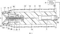
图1是表示第一实施方式的旋转雾化头型涂敷装置的纵剖视图。Fig. 1 is a longitudinal sectional view showing a rotary atomizing head type coating device according to a first embodiment.
图2是放大表示图1中的喷雾器的周围的纵剖视图。Fig. 2 is an enlarged longitudinal sectional view showing the periphery of the nebulizer in Fig. 1 .
图3是表示第一变型例的旋转雾化头型涂敷装置的纵剖视图。Fig. 3 is a longitudinal sectional view showing a rotary atomizing head type coating device according to a first modification.
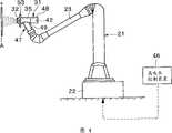
图4是表示第二实施方式的旋转雾化头型涂敷装置的正视图。Fig. 4 is a front view showing a rotary atomizing head type coating device according to a second embodiment.
图5是在破开罩部件的状态下放大表示图4中的涂敷机的正视图。Fig. 5 is an enlarged front view showing the coater in Fig. 4 with the cover member broken.
图6是表示图4中的涂敷机的纵剖视图。Fig. 6 is a longitudinal sectional view showing the coater shown in Fig. 4 .
图7是表示第二实施方式的涂敷机的图5的左侧视图。Fig. 7 is a left side view of Fig. 5 showing a coater according to a second embodiment.
图8是表示第三实施方式的旋转雾化头型涂敷装置的与图5相同的正视图。Fig. 8 is a front view similar to Fig. 5 showing a rotary atomizing head type coating device according to a third embodiment.
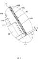
图9是放大表示图8中的a部分的主要部分放大正视图。Fig. 9 is an enlarged front view of main parts showing part a in Fig. 8 in an enlarged manner.
图10是表示第二变型例的颈部侧罩的与图9相同的主要部分放大正视图。Fig. 10 is an enlarged front view showing a neck side cover according to a second modification, the same as Fig. 9 .
图11是表示第四实施方式的旋转雾化头型涂敷装置的与图5相同的正视图。Fig. 11 is a front view similar to Fig. 5 showing a rotary atomizing head type coating device according to a fourth embodiment.
图12是表示第三变型例的旋转雾化头型涂敷装置的与图5相同的正视图。Fig. 12 is a front view similar to Fig. 5 showing a rotary atomizing head type coating device according to a third modification.
图13是表示第五实施方式的旋转雾化头型涂敷装置的与图5相同的正视图。Fig. 13 is a front view similar to Fig. 5 showing a rotary atomizing head type coating device according to a fifth embodiment.
图14是表示第六实施方式的旋转雾化头型涂敷装置的纵剖视图。Fig. 14 is a longitudinal sectional view showing a rotary atomizing head type coating device according to a sixth embodiment.
图15是从图14中的箭头XV-XV方向观察到的第六实施方式的高压放电电极的右侧视图。Fig. 15 is a right side view of the high-voltage discharge electrode of the sixth embodiment seen from the arrow XV-XV direction in Fig. 14 .
图16是表示第四变型例的旋转雾化头型涂敷装置的纵剖视图。Fig. 16 is a longitudinal sectional view showing a rotary atomizing head type coating device according to a fourth modification.
图17是从图16中的箭头XVII-XVII方向观察到的第四变型例的高压放电电极的右侧视图。FIG. 17 is a right side view of a high-voltage discharge electrode of a fourth modification seen from the direction of arrow XVII-XVII in FIG. 16 .
图18是在破开罩部件等的状态下表示第七实施方式的旋转雾化头型涂敷装置的正视图。18 is a front view showing a rotary atomizing head type coating device according to a seventh embodiment in a state where a cover member and the like are broken.
图19是在破开罩部件等的状态下表示第八实施方式的旋转雾化头型涂敷装置的正视图。Fig. 19 is a front view showing a rotary atomizing head type coating device according to an eighth embodiment in a state where a cover member and the like are broken.
图20是在破开罩部件等的状态下表示第五变型例的旋转雾化头型涂敷装置的与图19相同的正视图。Fig. 20 is a front view similar to Fig. 19 showing a rotary atomizing head type coating device according to a fifth modification with a cover member and the like broken.
具体实施方式Detailed ways
下面,作为本发明的实施方式的静电涂敷装置列举旋转雾化头型涂敷装置为例并按照附图进行详细说明。Hereinafter, as an electrostatic coating device according to an embodiment of the present invention, a rotary atomizing head type coating device will be taken as an example, and will be described in detail with reference to the drawings.
首先,图1及图2表示第一实施方式。图中,标号1是作为朝向处于接地电位的被涂物(未图示)喷雾涂料的涂料喷雾单元的喷雾器,该喷雾器1由下述的气动马达2、旋转雾化头3等构成。First, FIG. 1 and FIG. 2 show a first embodiment. In the figure,
标号2是由导电性金属材料构成的气动马达,该气动马达2由马达壳体2A和借助于静压空气轴承2B可旋转地支撑于该马达壳体2A内的中空的转轴2C以及固定于该转轴2C的基端一例的空气涡轮2D构成。并且,通过向空气涡轮2D供给驱动空气,气动马达2使转轴2C和旋转雾化头3以例如3000~100000rpm高速旋转。
标号3是安装在气动马达2的转轴2C的前端一侧的旋转雾化头,该旋转雾化头3由例如金属材料或导电性树脂材料构成。并且,旋转雾化头3在由气动马达2高速旋转的状态下,通过利用下述的供料管4供给涂料,利用离心力从前端一侧的喷出端缘3A呈雾状喷出该涂料。另外,旋转雾化头3借助于气动马达2等连接在下述的高电压发生器7上。由此,在进行静电涂敷的场合,能够对比旋转雾化头3整体施加高电压,能够使流过这些表面的涂料直接地带高电压。
标号4是穿过转轴2C内设置的供料管,该供料管4的前端一侧从转轴2C的前端突出而延伸到旋转雾化头3内。另外,在供料管4内设有涂料通道5,而且该涂料通道5借助于变色阀装置等连接在涂料供给源及清洗稀料供给源(均未图示)上。另外,在供料管的中间部位形成有下述的阀体6A离开就位的阀座4A。由此,供料管4在涂敷时通过涂料通道5朝向旋转雾化头3供给来自涂料供给源的涂料,而且在清洗时、变色时等供给来自清洗稀料供给源的清洗流体(稀料、空气等)。
此外,供料管4不限定于本实施方式,例如也可以做成内筒形成有涂料通道,外筒配置有清洗稀料通道的双层筒状。另外,涂料通道5不限定于如本实施方式那样通过供料管4内,也可以根据喷雾器1的种类采用各种通道方式。In addition, the
标号6是设置在涂料通道5的中间部位上的例如常闭型的涂料供给阀。该涂料供给阀6由:在涂料通道5内延伸且前端在阀座4A上离就位的阀体6A;位于该阀体6A的基端一侧并设置在液压缸6B内的活塞6C;将设置于液压缸6B内的阀体6A向阀关闭方向加力的阀簧6D;以及在液压缸6B内设置于与阀簧6D相反一例的受压室6E构成。并且,就涂料供给阀6而言,通过将供给阀驱动空气(控制空气)供给受压室6E,则克服阀簧6D而打开阀体6A,容许涂料在涂料通道5内流通。
标号7是作为连接在气动马达2上的高电压施加单元的高电压发生器,该高电压发生器7通过由多个电容器、二极管(均未图示)构成的多级式整流电路(所谓科克罗夫特电路)而构成。另外,高电压发生器7使从高电压控制装置8供给的直流的电源电压升压而发生例如-30~-150kV的高电压。此时,就高电压发生器7而言,由于设定了与高电压控制装置8供给的电源电压相应发生的高电压,因此,输出电压(高电压)由高电压控制装置8所控制。并且,高电压发生器7借助于高压电缆7A连接在气动马达2及旋转雾化头3上,通过该旋转雾化头3使涂料直接地带高电压。
标号9是安装有气动马达2和高电压发生器7的壳体部件。该壳体部件9利用例如POM(聚甲醛)、PET(聚对苯二甲酸乙二醇酯)、PEN(聚萘二甲酸乙烯酯)、PP(聚丙烯)、HP-PE(高压聚乙烯)、HP-PVC(高压聚氯乙烯)、PEI(聚醚亚胺)、PES(聚醚砜)、聚甲基戊烯等的绝缘树脂材料形成大致圆柱状。
并且,壳体部件9具有圆筒状的外表面9A,而且其后端9B做成较大直径的凸缘状。另外,在壳体部件9的前侧形成有容纳气动马达2的气动马达容纳孔9C,并在壳体部件9的后侧形成有容纳高电压发生器7的高电压发生器容纳孔9D。Furthermore, the
标号10是与壳体部件9的外表面9A隔着间隙设置的筒状的罩部件。并且,罩部件10作为具有高绝缘性、非吸水性的绝缘性树脂材料,使用例如PTFE(聚四氟乙烯)、POM(聚甲醛)或实施了表面憎水处理的PET(聚对苯二甲酸二乙醇酯)等形成。另外,罩部件10为了保持机械强度,例如以0.1~5mm左右厚度做成筒状。再有,在罩部件10的前端一侧设有呈环状向内圆周侧突出并封闭壳体部件9的前端一侧的前封闭部件11。
这里,就罩部件10而言,后端一侧安装在壳体部件9的较大直径的后端9B上,前端一侧安装在前封闭部件11上。但罩部件10和壳体部件9彼此在径向面对面的部位(罩部件10的轴向中间部位)大致沿着整个面与壳体部件9隔离。其结果,在罩部件10和壳体部件9之间形成横截面为环状的环状空间12。由此,环状空间12大致沿着整个面包围气动马达2及高电压发生器7的外周侧。并且,为了防止从罩部件10流向壳体部件9的漏电流,在罩部件10和壳体部件9之间以例如5mm以上的间隔尺寸形成环状空间12。Here, as for the
标号13是喷出整形空气的整形空气环,该整形空气环13以包覆旋转雾化头3的外周侧的方式借助于前封闭部件11设置在罩部件10的前端一侧。并且,整形空气环13作为与罩部件10大致相同的材料,使用例如PTFE、POM或实施了表面憎水处理的PET等做成筒状。另外,在整形空气环13上穿设有多个空气喷出孔13A,该空气喷出孔13A与设置在壳体部件9内的整形空气通道14连通。并且,通过整形空气通道14向空气喷出孔13A供给整形空气,空气喷出孔13A将该整形空气朝向从旋转雾化头3呈雾状喷出的涂料喷出。由此,整形空气对从旋转雾化头3呈雾状喷出来的涂料粒子的喷雾图形进行整形。
第一实施方式的旋转雾化头型涂敷装置具有如上所述的结构,下面对使用了该涂敷装置的涂敷动作进行说明。The rotary atomizing head type coating device according to the first embodiment has the above-mentioned configuration, and the coating operation using this coating device will be described below.
喷雾器1利用气动马达2使旋转雾化头3高速旋转,并在该状态下通过供料管4向旋转雾化头3供给涂料。由此,喷雾器1利用旋转雾化头3旋转时的离心力使涂料微粒化,并使之作为涂料粒子喷雾。另外,从整形空气环13供给整形空气,通过该整形空气控制由涂料粒子构成的喷雾图形。The
另外,在旋转雾化头3上,借助于气动马达2施加由高电压发生器7产生的高电压。由此,供给到旋转雾化头3上的涂料通过旋转雾化头3直接地带高电压,同时,成为带电涂料粒子沿着形成于旋转雾化头3和被涂物之间的静电场飞行,涂敷附着在被涂物上。In addition, on the rotary atomizing head 3 a high voltage generated by a
然而一般来讲,相对于空气的体积电阻系数可假定为无穷大,由各种绝缘性树脂材料(电介质材料)形成的壳体部件9的体积电阻系数为1012~1016Ωm程度。因此,壳体部件9的电阻低于空气的电阻。Generally, however, the volume resistivity to air can be assumed to be infinite, and the volume resistivity of the
与此相反,在第一实施方式中,由于做成在壳体部件9和罩部件10之间沿着这些壳体部件9和罩部件10互相面对面的部位的整个面设置环状空间12的结构。因此,能够减少电阻低于空气的壳体部件9与罩部件10接触的部位。由此,由于能够减少带高电压的罩部件10外表面的电荷通过壳体部件9的漏泄,因而能够保持罩部件10的带电状态,能够防止带电涂料粒子的附着。In contrast, in the first embodiment, since the
另外,在第一实施方式中,由气动马达2和旋转雾化头3构成喷雾器1。此时,带电涂料粒子有从旋转雾化头3向壳体部件9的外周侧喷出并在壳体部件9周围旋浮的倾向。另外,在对如汽车的车内那样的封闭空间进行涂敷时,有浮游的带电涂料粒子靠近壳体部件9一侧,并容易附着的倾向。与此相反,在本实施方式中,由于通过环状空间12能够保持罩部件10的带电状态,因而能够对由罩部件10的电荷所致的浮游的带电涂料粒子作用库伦排斥力,能够抑制涂料粒子附着到包覆喷雾器1的罩部件10上。In addition, in the first embodiment, the
再有,由于高电压发生器7做成对气动马达2施加高电压的结构。因此,通过气动马达2能够稳定地使罩部件10的外表面带高电压,能够防止涂料粒子的附着。Furthermore, since the
此外,在上述第一实施方式中,罩部件10和整形空气环13由不同部件形成。但本发明不限定于此,例如也可以如图3所示的第一变形例那样,将罩部件10′和整形空气环13′做成一体。Furthermore, in the first embodiment described above, the
另外,在第一实施方式中,整形空气环13使用绝缘树脂材料形成。但是,本发明不限定于此,例如也可以使用导电性金属材料形成整形空气环。在这种场合,在由金属材料构成的整形空气环上借助于气动马达施加与涂料相同极性的高电压。由此,由于整形空气环作为相斥电极起作用,因此,能够防止涂料粒子附着在整形空气环上。In addition, in the first embodiment, the shaping
下面,图4~图7表示第二实施方式的旋转雾化头型涂敷装置。第二实施方式的特征在于,壳体部件由在前后方向延伸并在前侧保持涂料喷雾单元的躯干部和由该躯干部分支了的颈部构成,而罩部件由包覆壳体部件的躯干部的躯干部一侧罩和包覆上述壳体部件的颈部的颈部侧罩构成。Next, FIGS. 4 to 7 show a rotary atomizing head type coating device according to a second embodiment. The second embodiment is characterized in that the housing part is made of a trunk part extending in the front-rear direction and holding the paint spray unit on the front side, and a neck branched from the trunk part, and the cover part consists of a trunk part covering the case part. The trunk part side cover of the upper part and the neck side cover covering the neck part of the above-mentioned case member are constituted.
图中,标号21是用于进行自动涂敷作业的机器人装置,该机器人装置21用来执行使用了下述的涂敷机31的涂敷作业。并且,机器人装置21大致由底盘22和可旋转且可摆动地设置在该底盘22上并具有多个关节的机器人臂23(手臂)构成。并且,机器人装置21使涂敷机31相对被涂物A移动,而且连接在地线上。In the figure,
标号31是安装在机器人装置21上的盒式涂敷机,该涂敷机31大致由下述的喷雾器32、壳体部件35、盒42等构成。
标号32是作为向处于接地电位的被涂物A呈雾状喷出涂料的涂料喷雾单元的喷雾器,喷雾器32由下述的气动马达33、旋转雾化头34等构成。
标号33是由导电性金属材料构成的气动马达,该气动马达33由马达壳体33A和借助于静压空气轴承33B可旋转地支撑于该马达壳体33A内的中空的转轴33C以及固定于该转轴33C的基端一侧的空气涡轮33D构成。并且,利用通过下述的空气通道39向空气涡轮33D供给驱动空气,气动马达33以例如3000~100000rpm使转轴33C和旋转雾化头34高速旋转。
标号34是安装在气动马达33的转轴33C的前端一侧的旋转雾化头,该旋转雾化头34由例如金属材料或导电性树脂材料构成。并且,旋转雾化头34在由气动马达33高速旋转的状态下,通过下述的供料管44供给涂料,利用离心力从前端一侧的喷出端缘4A呈雾状喷出该涂料。另外,在旋转雾化头34上通过气动马达33等连接有下述的高电压发生器45。由此,在进行静电涂敷的场合,能够对旋转雾化头34整体施加高电压,能够使流过这些表面的涂料直接地带高电压。
标号35是用于安装气动马达33等的壳体部件。该壳体部件35与第一实施方式的壳体部件9相同地由例如POM(聚甲醛)、PET(聚对苯二甲酸二乙醇酯)、PEN(聚萘二价酸乙烯酯)、PP(聚丙烯)、HP-PE(高压聚乙烯)、HP-PVC(高压聚氯乙烯)、PEI(聚醚亚胺)、PES(聚醚砜)、聚甲基戊烯等的绝缘树脂形成。
另外,壳体部件35由轴向(前后方向)延伸的圆筒状的躯干部36和从该躯干部36的轴向的中间位置朝向外周侧倾斜地分支的颈部37构成。In addition, the
并且,在躯干部36的前侧形成有容纳气动马达33的气动马达容纳孔36A,而且在躯干部36的后侧形成有用于安装下述的盒42的储料罐43的储料罐安装部36B。另外,在躯干部36内,沿轴向延伸地形成有通过气动马达容纳孔36A和储料罐安装部36B的中心位置的供料管贯通孔36C。Also, an air
另一方面,在颈部37内形成有容纳下述的高电压发生器45的高电压发生器容纳孔37A。并且,颈部37的前端使用由绝缘性树脂材料构成的筒状的连接部件38安装在机器人装置21的机器人臂23的前端。再有,在壳体部件35内形成有向气动马达33供给驱动空气的空气通道39,而且形成有向下述盒42供给涂料排出量控制用推压液体的推压液体通道40。On the other hand, a high voltage
标号41是以围绕旋转雾化头34的方式设置于壳体部件35的躯干部36的前端一侧的整形空气环,该整形空气环41使用例如导电性金属材料形成,并与气动马达33电连接。另外,在整形空气环41上穿设有多个空气喷出孔41A,该空气喷出孔41A向从旋转雾化头34呈雾状喷出的涂料喷出整形空气。
标号42是向旋转雾化头34供给涂料的涂敷用的盒,该盒42大致由作为沿轴向(前后方向)延伸的圆筒体(液压缸)形成的储料罐43和从该储料罐43向轴向延伸的供料管44和将上述储料罐43内分隔成涂料容纳室和推压液体容纳室的活塞(均未图示)等构成。
另外,盒42以供料管44穿过供料管贯通孔36C内的状态安装于壳体部件35的储料罐安装部36B上。并且,在进行涂敷时,通过使推压液体通过壳体部件35的推压液体通道40而供给到推压液体容纳室,从而使活塞滑动位移,通过供料管44向旋转雾化头34喷出储料罐43内的涂料。另外,在填充涂料时,将盒42从储料罐安装部36B拆卸后安装在涂料填充装置(未图示)上,并使涂料通过供料管44填充到储料罐43的涂料容纳室内。In addition, the
标号45是作为安装在壳体部件35的颈部37内部的高电压施加单元的高电压发生器,该高电压发生器45,其输入一侧借助于机器人装置21连接在外部的高电压控制装置46上,输出一侧连接在气动马达33上。并且,高电压发生器45通过由例如多个电容器、二极管(均未图示)构成的多级式整流电路(所谓科克罗夫特电路)构成。
另外,高电压发生器45对从高电压控制装置46供给的直流的电源电压进行升压而发生例如-30~-150kV的高电压。此时,就高电压发生器45而言,由于是根据高电压控制装置46控制的电源电压来设定所产生的高电压,因此,输出电压(高电压)可以由高电压控制装置46控制。并且,高电压发生器45借助于高压电缆45A并通过气动马达33及旋转雾化头34使涂料直接地带高电压。In addition, the high-
标号47是设置成包覆壳体部件35的外表面的罩部件,该罩部件47作为具有高绝缘性、非吸水性的氟系绝缘树脂,使用例如包括PTFE(聚四氟乙烯)、ETFE(乙烯与四氟乙烯的共聚物)等的氟系树脂膜构件形成。另外,罩部件47由包围躯干部36的外表面36D的躯干部一侧罩48和包围颈部37的外表面37B的颈部一侧罩49构成。并且,各个罩48、49,通过将具有例如0.1~5mm左右的厚度尺寸的树脂膜构件弄圆而分别做成筒状。
这里,躯干部一侧罩48从躯干部36的周围向后方延伸。由此,躯干部一侧罩48在包覆躯干部36的外表面36D的同时,也包覆盒42的储料罐43的外表面。另外,躯干部一侧罩48安装于设置在躯干部36的前后方向的两端侧上的圆环状的凸缘部50上。另一方面,颈部一侧罩49安装于设置在颈部37的长度方向的中部位置的圆环状的凸缘部51和设置在颈部37的前端位置的连接部件38上。Here, the trunk side cover 48 extends rearward from the periphery of the
并且,躯干部一侧罩48中与躯干部36的外表面36D互相面对的部位,除了与凸缘部50接触的少许部位以外,大致沿着整个面与躯干部36隔开。另外,罩部件47的颈部一侧罩49中与颈部37的外表面37B互相面对的部位,除了与凸缘部51、连接部件38接触的少许部位以外,大致沿着整个面与颈部37隔开。In addition, parts of the trunk side cover 48 facing the
由此,在躯干部36和躯干部一侧罩48之间形成横截面为环状的环状空间52,而且在颈部37和颈部一侧罩49之间也形成横截面为环状的环状空间52。因此,在罩部件47和壳体部件35之间大致沿着整个面形成环状空间52。其结果,环状空间52大致沿着整个面包围气动马达33及高电压发生器45的外周侧。并且,为了防止从罩部件47流向壳体部件35的漏电流,在罩部件47和壳体部件35之间以例如5mm以上的间隔尺寸形成环状空间52。Thus, an
标号53是设置于躯干部一侧罩48的外周侧的高压放电电极,该高压放电电极53使用导电性材料形成,由下述的支撑臂部54和环部55构成。
标号54是辐射状地设置于整形空气环41的周围的支撑臂部,该支撑臂部54从壳体部件35一侧向躯干部一侧罩48的外周侧沿着径向延伸。并且,在整形空气环41的周围以等间距设置有例如四条支撑臂部54,以支撑环部55。
标号55是设置于支撑臂部54的前端上的环部,该环部55使用例如金属等的导电性材料做成圆环状。另外,环部55位于气动马达33的周围,并包围躯干部一侧罩48的前侧。并且,环部55做成比躯干部一侧罩48的外经还大的圆形,配置成与气动马达33的转轴33C为同轴的大致同心圆状。由此,环部55沿其整个圆周与躯干部一侧罩48之间的距离大致一定。并且,环部55借助于支撑臂部54、整形空气环41连接在气动马达33上。由此,对环部55施加由高电压发生器45产生的高电压,环部55进行放电,释放出与带电涂料粒子相同极性的离子。
第二实施方式的旋转雾化头型涂敷装置具有如上所述的结构,下面对作为涂敷装置的动作进行说明。The rotary atomizing head type coating device according to the second embodiment has the above-mentioned configuration, and the operation as the coating device will be described below.
若使用传送装置等将被涂物A配置在机器人装置21的附近,则机器人装置21A根据预先存储的示教动作,进行示教再现动作,使涂敷机31移动到被涂物A附近。When the object A to be coated is placed near the
此时,涂敷机31利用气动马达33使旋转雾化头34高速旋转,在该状态下,通过供料管44向旋转雾化头34供给储料罐43内的涂料。由此,涂敷机31由旋转雾化头34旋转时的离心力使涂料微粒化,喷雾成作为涂料粒子。另外,从整形空气环41供给整形空气,通过该整形空气控制由涂料粒子构成的喷雾图形。At this time, the
另外,借助于气动马达33对旋转雾化头34施加由高电压发生器45产生的高电压。由此,供给到旋转雾化头34上的涂料通过旋转雾化头34直接地带高电压,同时,成为带电涂料粒子而沿着形成于旋转雾化头34和被涂物A之间的静电场飞行,涂敷附着在处于接地电位的被涂物A上。In addition, a high voltage generated by a
另外,在第二实施方式中,做成在躯干部一侧罩48的外周侧设置高压放电电极53的结构。因此,来自高电压发生器45的高电压借助于气动马达33等施加到环部55上,并从环部55放电。In addition, in the second embodiment, the high-
由此,高压放电电极53放出与带电涂料粒子相同极性的离子,并能够极力使罩部件47带具有相同极性的电荷。另外,高压放电电极53能够使通过环部55的放电而使带电量衰减的涂料粒子再次带电。其结果,能够在再次带电的涂料粒子与高压放电电极53或罩部件47之间作用相斥力,能够可靠地防止涂料粒子附着到罩部件47上。Accordingly, the high-
这样,在第二实施方式中,做成在壳体部件35和罩部件47之间沿着这些壳体部件35和罩部件47互相面对的部位的大致整个面设置环状空间52的结构。Thus, in the second embodiment, the
一般来讲,相对空气的体积电阻系数可假定为无穷大,由各种绝缘性树脂材料(电介质材料)形成的壳体部件35的体积电阻系数为1012~1016Ωm程度。因此,壳体部件35的电阻低于空气电阻。Generally, the volume resistivity to air can be assumed to be infinite, and the volume resistivity of the
与此相反,由于在壳体部件35和罩部件47之间设置环状空间52,因而,由该环状空间52能够减少壳体部件35与罩部件47接触的部位。因此,由于能够减少带高电压的罩部件47外表面的电荷通过壳体部件35漏泄,因而能够保持罩部件47的带电状态,能够防止带电涂料粒子的附着。On the other hand, since the
另外,在本实施方式中,在涂敷过程中从旋转雾化头34喷雾的一部分带电涂料粒子有在罩部件47的外周侧悬浮的倾向。但由于通过环状空间52能够保持罩部件47的带电状态,因而能够对因罩部件47的电荷而悬浮的带电涂料粒子作用库伦相斥力,能够抑制涂料粒子附着到包覆喷雾器32的罩部件47上。In addition, in the present embodiment, part of the charged paint particles sprayed from the
再有,高电压发生器45做成对气动马达33、旋转雾化头34、整形空气环41等施加高电压的结构。因此,通过气动马达35等能够稳定地使罩部件47的外表面带高电压,能够防止涂料粒子附着。Furthermore, the
尤其是在第二实施方式中,由于罩部件47由包覆壳体部件35的躯干部36的躯干部一侧罩48和包覆壳体部件35的颈部37的颈部一侧罩49构成,因此,能够使用躯干部一侧罩48及颈部一侧罩49包覆壳体部件35的外表面整体。由此,能够使躯干部一侧罩48和颈部一侧罩49带电并防止带电涂料粒子的附着。In particular, in the second embodiment, since the
另外,由于罩部件47使用氟系绝缘树脂膜构件形成,因此,能够使用例如具有憎水性的PTFE等形成罩部件47,并由于憎水作用能够防止带电涂料粒子附着到罩部件47上。另外,通过使氟系绝缘树脂膜构件带电,能够对带电涂料粒子作用相斥力。此外,氟系绝缘树脂膜构件由于吸湿性较低而体积电阻系数较大,因此,在这些部件上所带的电荷不易漏泄。因此,能够稳定地保持罩部件47的带电状态。In addition, since the
另外,在涂料附着在罩部件47上的场合,薄膜状的罩部件47能够从壳体部件35上容易地剥下并更换。由此,与清洗壳体部件35相比,能够缩短涂敷机31的维修保养时间,能够提高涂敷作业的生产效率。In addition, when paint adheres to the
另外,在第二实施方式中,由于做成在躯干部一侧罩48的外周侧设置高压放电电极53的结构,因此,来自高电压发生器45的高电压借助于气动马达33、整形空气环41等施加到环部55上并放电。因此,高压放电电极53放出与带电涂料粒子相同极性的离子,并能够极力使罩部件47带具有相同极性的电荷。另外,高压放电电极53能够使因环部55的放电而带电量衰减的涂料粒子再次带电。In addition, in the second embodiment, since the high-
其结果,能够在再次带电的涂料粒子与高压放电电极53或罩部件47之间作用相斥力。因此,由该斥力能够防止带电涂料粒子靠近罩部件47,而且通过带高电压的罩部件47能够防止带电涂料粒子附着。As a result, a repulsive force can act between the recharged paint particles and the high-
另外,由于高压放电电极53由支撑臂部54及环部55构成,因此,由包围躯干部一侧罩48的环部55能够在罩部件47的周围形成高压静电场,能够使带电涂料粒子远离罩部件47。再有,由于环部55包围躯干部一侧罩48,因而与省略了高压放电电极53的场合相比,通过环部55的高压放电,能够在较广的范围使罩部件47带高压的电荷。由此,能够在罩部件47的较广的范围防止带电涂料粒子附着。In addition, since the high-
图8及图9表示第三实施方式的旋转雾化头型涂敷装置,第三实施方式的特征在于,躯干部一侧罩使用由氟系树脂材料构成的氟系树脂膜构件形成,颈部一侧罩使用在具有绝缘性的两片绝缘膜之间夹着具有半导电性的半导电膜的层叠膜构件形成。此外,在第三实施方式中,对于与第二实施方式相同的构成要素标上相同符号并省略其说明。8 and 9 show a rotary atomizing head type coating device according to a third embodiment. The third embodiment is characterized in that the trunk side cover is formed using a fluororesin film member made of a fluororesin material, and the neck portion The one-side cover is formed using a laminated film member in which a semiconductive semiconductive film is sandwiched between two insulating films having insulating properties. In addition, in the third embodiment, the same reference numerals are attached to the same components as those in the second embodiment, and description thereof will be omitted.
标号61是设置成包覆壳体部件35的外表面的罩部件,该罩部件61由包围躯干部36的外表面36D和储料罐43的躯干部一侧罩62和包围颈部37的外表面37B的颈部一侧罩63构成。
这里,躯干部一侧罩62与第二实施方式的躯干部一侧罩48相同地使用例如包括PTFE等的氟系树脂膜构件形成。Here, the trunk side cover 62 is formed using a fluororesin film member including, for example, PTFE, as in the trunk side cover 48 of the second embodiment.
另一方面,颈部一侧罩63使用在具有绝缘性的两片绝缘膜63A、63B之间夹着具有半导电性的半导电膜63C的层叠膜构件形成。这时,绝缘膜63A、63B使用例如包括PTFE等的氟系树脂形成,其体积电阻系数设定为例如1016Ωm以上。另一方面,半导电膜63C作为电阻比绝缘膜63A、63B低的材料,使用例如体积电阻系数为1011Ωm以下的聚乙烯等树脂形成。并且,这些膜63A、63B、63C的厚度尺寸分别设定为例如0.1~1.0mm左右,优选设定为0.1~0.3mm左右。On the other hand, the
这里,躯干部一侧罩62安装于设置在躯干部36的前后方向的两端侧的凸缘部50上。另外,颈部一侧罩63安装于设置在颈部37的长度方向的中部位置的凸缘部51上和设置在颈部37的前端位置的连接部件38上。并且,躯干部一侧罩62中与躯干部36的外表面36D互相面对的部位,除了与凸缘部50接触的少许部位以外,大致沿着整个面与躯干部36隔开。Here, the trunk part side cover 62 is attached to the
另外,颈部一侧罩63中与颈部37的外表面37B互相面对的部位,除了与凸缘部51、连接部件38接触的少许部位以外,大致沿着整个面与颈部37隔开。由此,在罩部件61和壳体部件35之间,与第二实施方式的环状空间52相同地大致沿着整个面形成环状空间64。由此,环状空间64大致沿着整个面包围气动马达及高电压发生器的外周侧。In addition, the portion of the neck side cover 63 that faces the
另外,颈部一侧罩63的前端部朝向颈部37的前端延伸并与机器人臂23接触。但在颈部一侧罩63的前端部,通过去除半导电膜63C而在半导电膜63C和机器人臂23之间形成空间。即,如图9所示,相对颈部一侧罩63的绝缘膜63A、63B与机器人臂23接触,半导电膜63C以例如10mm以上的间距尺寸离开机器人臂23。由此,颈部一侧罩63防止半导电膜63C所带的电荷朝向成为接地件的机器人臂23放电。In addition, the front end of the
这样,第三实施方式也能得到与第二实施方式相同的作用效果。尤其是在第三实施方式中,躯干部一侧罩62使用氟系树脂膜构件形成,颈部一侧罩63使用层叠膜构件形成。此时,喷雾器32、整形空气环41及高压放电电极53由高电压发生器45施加高电压。因此,靠近喷雾器32等的躯干部一侧罩62容易带电,能够容易地抑制涂料附着到躯干部一侧罩62上。In this way, also in the third embodiment, the same effect as that of the second embodiment can be obtained. In particular, in the third embodiment, the trunk side cover 62 is formed using a fluororesin film member, and the
与此相反,离开喷雾器32等的颈部一侧罩63有不易带电的倾向。另外,即使使电子或负离子流均匀地撞击到罩部件61上,也不见得电荷均匀地附着在罩部件61的表面上。即,附着在罩部件61的表面上的电荷的均匀性较大地依赖于罩部件61内的电位。此时,就壳体部件35的颈部37而言,相对于基端一侧由于高电压发生器45而处在高电位,前端一侧由于机器人臂23而处在接地电位。因此,在颈部一侧罩63中,电荷的均匀性受到颈部37的电位梯度的阻碍。因此,有在颈部一侧罩63中靠近喷雾器32等的部位容易带电,而离开喷雾器32等的部位不易带电的倾向。On the contrary, the neck side cover 63 away from the
然而,在第三实施方式中,颈部一侧罩63使用在两片绝缘膜63A、63B之间夹着半导电膜63C的层叠膜构件形成。此时,半导电膜63C与绝缘膜63A、63B相比,其体积电阻系数小,电荷容易移动。在直流电场中,半导电膜63C与绝缘膜63A、63B相比,其电阻极低,沿着整个面大致处在同电位。受该半导电膜63C的稳定电位的影响,能够得到绝缘膜63A的表面更均匀地带电的效果。However, in the third embodiment, the
即,当绝缘膜63A的表面带负极性电时,绝缘膜63A的背面因感应带电现象而带正极性电。此时,由于在绝缘膜63A的背面设有半导电膜63C,因此,绝缘膜63A的背面的正极性电荷便通过半导电膜63C移动,并沿着颈部一侧罩63的整体扩散。随之,附着在绝缘膜63A的表面上的带负极性电的离子由于与正极性电荷之间的库仑力也沿着颈部一侧罩63的整体均匀地扩散。That is, when the surface of the insulating
其结果,与不设置半导电膜63C的场合相比,能够在绝缘膜63A的表面得到带更均匀的负极性电。因此,当负离子飞来时,能够使外表面一侧的绝缘膜63A的整个面带均匀的电荷。As a result, more uniform negative polarity charging can be obtained on the surface of the insulating
由此,能够使颈部一侧罩63整体可靠地带电而防止涂料粒子附着,而且能够防止因不均匀的电荷分布所引起的电场集中。因此,能够在绝缘膜63A与带电涂料粒子之间产生稳定的相斥力,能够防止局部的涂料的附着或堆积。Accordingly, it is possible to securely charge the entire neck side cover 63 to prevent adhesion of paint particles, and to prevent electric field concentration due to uneven charge distribution. Therefore, a stable repulsive force can be generated between the insulating
此外,在第三实施方式中,颈部一侧罩63的前端部做成通过去除半导电膜63C而使半导电膜63C和机器人臂23之间绝缘的结构。但本发明不限定于此,例如,如图10所示第二变型例,颈部一侧罩63′的前端部也可以做成通过使两片绝缘膜63A′、63B′熔接而使半导电膜63C′和机器人臂23之间绝缘的结构。In addition, in the third embodiment, the front end portion of the
图11表示第四实施方式的旋转雾化头型涂敷装置。第四实施方式的特征在于,颈部一侧罩做成从壳体部件的颈部向机器人臂延伸并包覆该机器人臂的结构。此外,在第四实施方式中,对于与第二实施方式相同的构成要素标上相同符号并省略其说明。Fig. 11 shows a rotary atomizing head type coating device according to a fourth embodiment. The fourth embodiment is characterized in that the neck side cover is configured to extend from the neck of the casing member toward the robot arm and to cover the robot arm. In addition, in the fourth embodiment, the same reference numerals are assigned to the same components as those in the second embodiment, and description thereof will be omitted.
标号71是设置成包覆壳体部件35的外表面的罩部件,该罩部件71由包围躯干部36的外表面36D和储料罐43的外表面的躯干部一侧罩72和包围颈部37的外表面37B的颈部一侧罩73构成。并且,躯干部一侧罩72与第二实施方式中的躯干部一侧罩48相同地使用例如包括PTFE等的氟系树脂膜构件形成。另一方面,颈部一侧罩73与第三实施方式中的颈部一侧罩63大致相同地由在具有绝缘性的两片绝缘膜之间夹着具有半导电性的半导电膜的层叠膜构件形成。
这里,躯干部一侧罩72安装于设置在躯干部36的前后方向的两端侧的凸缘部50上。另外,颈部一侧罩73安装于设置在颈部37的长度方向的中部位置的凸缘部51和设置在颈部37的前端位置的连接部件38上。并且,躯干部一侧罩72中与躯干部36的外表面36D互相面对的部位,除了与凸缘部50接触的少许部位以外,大致沿着整个面与躯干部36隔开。Here, the trunk part side cover 72 is attached to the
另外,颈部一侧罩73中与颈部37的外表面37B互相面对的部位,除了与凸缘部51、连接部件38接触的少许部位以外,大致沿着整个面与颈部37隔开。由此,在罩部件71和壳体部件35之间,与第二实施方式的环状空间52相同地大致沿着整个面形成环状空间74。由此,环状空间74大致沿着整个面包围气动马达及高电压发生器的外周侧。In addition, the portion of the neck side cover 73 that faces the
另外,颈部一侧罩73从颈部37向机器人臂23延伸并包覆机器人臂23的前端一侧。再有,颈部一侧罩73做成从基端一侧向前端一侧逐渐扩开的锥体状。即,颈部一侧罩73做成与机器人臂23的间距尺寸随着靠近处在接地电位的机器人臂23而变大的结构。由此,颈部一侧罩73充分地确保了与机器人臂23的距离,防止了朝向带了电荷的机器人臂23放电、漏泄。In addition, the
这样,第四实施方式也能得到与第二、第三实施方式相同的作用效果。尤其是在第四实施方式中,做成使颈部一侧罩73的端部从壳体部件35的颈部37朝向接地件即机器人臂23伸长,将颈部一侧罩73套在机器人臂23上的结构。因此,颈部一侧罩73的端部不是与接地件即机器人臂23接触而是隔开。In this way, the fourth embodiment can also obtain the same effects as those of the second and third embodiments. Especially in the fourth embodiment, the end portion of the
因此,即使颈部一侧罩73的表面多少被涂料污染,在颈部一侧罩73的端部和机器人臂23之间也没有带电电荷漏泄。另外,由于颈部一侧罩73包覆壳体部件35的颈部37,因此,颈部一侧罩73的里面不会直接地暴露在涂料粒子悬浮的外界。因此,颈部一侧罩73的里面不会被涂料污染,而且带电电荷也不会从颈部一侧罩73的里面漏泄。因此,能够可靠地保持颈部一侧罩73的带电状态,能够防止涂料污染的增加。Therefore, even if the surface of the
另一方面,例如,如第三实施方式,在颈部一侧罩63的端部接触了机器人臂23的场合,因附着在颈部一侧罩63的表面上的涂料,使颈部一侧罩63的表面的电阻下降。由此,通过与接地件即机器人臂23的接触部位,颈部一侧罩63的带电电荷容易漏泄,颈部一侧罩63和带电涂料之间的相斥力降低,涂料容易附着。On the other hand, for example, as in the third embodiment, when the end of the neck side cover 63 contacts the
另外,由于通过颈部一侧罩73包覆机器人臂23的外周侧,因此,即使在机器人臂23接地的场合,也能够防止带电涂料粒子附着到处在接地电位的机器人臂23上。In addition, since the outer peripheral side of the
此外,在第四实施方式中,颈部一侧罩73做成与机器人臂23的间距尺寸随着靠近机器人臂23而逐渐变大的锥体状。但本发明不限定于此,例如,如图12所示的第三变型例,颈部一侧罩73′也可以做成与机器人臂23的间距尺寸一定的筒状。In addition, in the fourth embodiment, the
下面,图13表示第五实施方式的旋转雾化头型涂敷装置。第五实施方式的特征在于,使用层叠膜形成了罩部件整体。此外,在第五实施方式中,对于与第二实施方式相同的构成要素标上相同符号并省略其说明。Next, FIG. 13 shows a rotary atomizing head type coating device according to a fifth embodiment. The fifth embodiment is characterized in that the entire cover member is formed using a laminated film. In addition, in the fifth embodiment, the same reference numerals are assigned to the same components as those in the second embodiment, and description thereof will be omitted.
标号81是设置成包覆壳体部件35的外表面的罩部件,该罩部件81与第三实施方式的颈部一侧罩63大致相同,由在具有绝缘性的两片绝缘膜之间夹着具有半导电性的半导电膜的层叠膜构件形成。另外,罩部件81由包围躯干部36的外表面36D的躯干部一侧罩82和包围颈部37的外表面37B的颈部一侧罩83构成。并且,在罩部件81和壳体部件35之间,与第二实施方式的环状空间52相同,大致沿着整个面形成有环状空间84。Reference numeral 81 is a cover member provided so as to cover the outer surface of the
这样,第五实施方式也能得到与第二、第三、第四实施方式相同的作用效果。尤其是在第五实施方式中,由于通过层叠膜构件形成了罩部件81,因此,即使由于例如壳体部件35等的电位梯度而在罩部件81中局部地存在不易带电荷的部位时,也能够使罩部件81的半导电膜沿着整个面处在大致相同电位。因此,通过使用半导电膜能够消除壳体部件35等的电位梯度的影响。In this way, the fifth embodiment can also obtain the same effects as those of the second, third, and fourth embodiments. In particular, in the fifth embodiment, since the cover member 81 is formed by laminating film members, even if there is a portion in the cover member 81 that is not easily charged due to the potential gradient of the
其结果,当负离子飞来时,能够使罩部件81中外表面一侧的绝缘膜的整体可靠而均匀地带电。由此,能够使罩部件81整体可靠地带电而防止带电涂料粒子的附着,而且能够防止因不均匀的电荷分布引起的电场集中,还能够防止部分涂料的附着或堆积。As a result, when negative ions fly, the entire insulating film on the outer surface side of the cover member 81 can be reliably and uniformly charged. Accordingly, it is possible to securely charge the entire cover member 81 to prevent adhesion of charged paint particles, prevent electric field concentration due to uneven charge distribution, and prevent partial adhesion or accumulation of paint.
下面,图14及图15表示第六实施方式的旋转雾化头型涂敷装置,第六实施方式的特征在于,做成在高压放电电极的环部设置了朝向与被涂物相反的方向延伸的针状电极部的结构。此外,在第六实施方式中,对于与第二实施方式相同的构成要素标上相同符号并省略其说明。Next, Fig. 14 and Fig. 15 show the rotary atomizing head type coating device according to the sixth embodiment. The structure of the needle electrode part. In addition, in the sixth embodiment, the same reference numerals are assigned to the same components as those in the second embodiment, and description thereof will be omitted.
标号91是设置于躯干部一侧罩48的外周侧的高压放电电极,该高压放电电极91使用导电性材料形成,由下述的支撑臂部92、环部93、电极部94构成。
标号92是辐射状地设置于整形空气环41的周围的支撑臂部,该支撑臂部92从壳体部件35一侧朝向躯干部一侧罩48的外周侧沿径向延伸。并且,在整形空气环41的周围以等间距设置有例如四条支撑臂部92,以支撑环部93。
标号93是设置于支撑臂部92的前端上的环部,该环部93使用例如金属等导电性材料做成圆环状。另外,环部93位于气动马达33的周围,包围躯干部一侧罩48的前侧。并且,环部93做成比躯干部一侧罩48的外经还大的圆形,配置成与气动马达33的转轴33C同轴的大致同心圆状。由此,环部93沿其整个圆周与躯干部一侧罩48之间的距离为大致一定。并且,环部93借助于支撑臂部92、整形空气环41连接在气动马达33上。由此,对环部93施加由高电压发生器45产生的高电压。
标号94是设置在环部93上的电极部,该电极部94由从环部93朝向与被涂物相反的方向(后侧)延伸并由金属等导电材料构成的针状电极形成。另外,沿着环部93的整个圆周以等间距排列设有多个电极部94。并且,电极部94的朝向配设为与气动马达的轴线(转轴)平行或在俯角为10°、仰角为20°的范围内。
这样,第六实施方式也能得到与第二、第三、第四、第五实施方式相同的作用效果。尤其是在第六实施方式中,由于做成在环部93上设置了针状的电极部94的结构,因而能够使电场集中在电极部94的前端,从而能够容易且稳定地进行高电压放电。另外,由于电极部94在离开被涂物的方向延伸,因此,通过在电极部94的前端进行高电压放电,从而能够使直到罩部件47的后侧都带高电压的电荷。由此,能够在罩部件47的较广的范围防止带电涂料粒子的附着。In this way, the sixth embodiment can also obtain the same effects as those of the second, third, fourth, and fifth embodiments. In particular, in the sixth embodiment, since the needle-shaped
此外,在第六实施方式中,做成由针状电极形成电极部94,在环部93上设置多个电极部94的结构。但本发明不限定于此,也可以做成例如,如图16及图17所示的第四变型例的放电环的结构。即,放电环也可以由环部93′和沿着该环部93′的整个圆周呈叶片状并向后方突出的电极部94′构成。在这种场合,只要将一片叶片弯折成环状即可。在这种场合,叶片状的电极部94′既可以做成夹着环部93′设置在接近被涂物的一侧(前侧)和背离被涂物的一侧(后侧)双方的结构,也可以做成仅设置在远离被涂物的一侧(后侧)的结构。In addition, in the sixth embodiment, the
下面,图18表示第七实施方式的旋转雾化头型涂敷装置,本实施方式的特征在于,做成将不具有分支部分的壳体部件安装在机器人臂上的结构。此外,在第七实施方式中,对于与第二实施方式相同的构成要素标上相同符号并省略其说明。Next, FIG. 18 shows a rotary atomizing head type coating device according to a seventh embodiment. The characteristic of this embodiment is that a case member having no branch portion is attached to a robot arm. In addition, in the seventh embodiment, the same reference numerals are assigned to the same components as those in the second embodiment, and description thereof will be omitted.
标号101是第七实施方式的涂敷机,该涂敷机101安装于机器人臂23的前端,大致由喷雾器32、壳体部件102等构成。
标号102是第七实施方式的壳体部件,该件壳体部件102与第一实施方式的壳体部件9大致相同地由绝缘性树脂材料做成大致圆柱形,而且安装有喷雾器32和高电压发生器45。另外,在壳体部件102的前侧形成有容纳气动马达33的气动马达容纳孔102A,而且在壳体部件102的后侧形成有容纳高电压发生器45的高电压发生器容纳孔102B。
另外,在壳体部件102的前端一侧安装有由导电性金属材料构成的整形空气环41,而且壳体部件102的后端一侧安装于机器人臂23的前端。再有,在整形空气环41的外周侧安装有由支撑臂部54和环部55构成的高压放电电极53。In addition, a shaping
标号103是包覆壳体部件102的外表面102C并设置成筒状的罩部件,该罩部件103与例如第二实施方式的罩部件47大致相同地使用氟系树脂膜构件做成筒状。并且,罩部件103沿着壳体部件102朝向机器人臂23延伸。由此,罩部件103与第四实施方式的罩部件71相同地包覆壳体部件102的外表面102C,而且也包覆机器人臂23的外表面。
另外,罩部件103安装于设置在壳体部件102的前后方向的两端侧的圆环状的凸缘部104上。并且,罩部件103中与壳体部件102的外表面102C互相面对的部位,除了与凸缘部104接触的少许部位以外,大致沿着整个面与壳体部件102隔开。由此,在罩部件103和壳体部件102之间大致沿着整个面形成横截面为环状的环状空间105。由此,环状空间105大致沿着整个面包围气动马达33及高电压发生器45的外周侧。In addition, the
这样,第七实施方式也能得到与第二、第四实施方式相同的作用效果。In this way, the seventh embodiment can also obtain the same effects as those of the second and fourth embodiments.
下面,图19表示第八实施方式的旋转雾化头型涂敷装置,本实施方式的特征在于,高电压发生器做成对位于罩部件的外侧的外部电极施加高电压的结构。此外,在第八实施方式中,对于与第二实施方式相同的构成要素标上相同符号并省略其说明。Next, FIG. 19 shows a rotary atomizing head type coating device according to an eighth embodiment. The characteristic of this embodiment is that the high voltage generator is configured to apply a high voltage to an external electrode positioned outside the cover member. In addition, in the eighth embodiment, the same reference numerals are assigned to the same constituent elements as those in the second embodiment, and description thereof will be omitted.
标号111是第八实施方式的涂敷机,该涂敷机111安装于机器人臂23的前端,大致由喷雾器32、壳体部件112等构成。
标号112是第八实施方式的壳体部件,该壳体部件112由绝缘性树脂材料做成大致圆柱形,而且安装有喷雾器32。另外,在壳体部件102的前侧形成有容纳气动马达33的气动马达容纳孔112A。再有,在壳体部件112的前端一侧安装有整形空气环41,而且壳体部件112的后端一侧安装于机器人臂23的前端。
标号113是包覆壳体部件112的外表面112B并设置成筒状的罩部件,该罩部件113与例如第二实施方式的罩部件47大致相同地使用氟系树脂膜构件做成筒状。并且,罩部件113沿着壳体部件112朝向机器人臂23延伸。由此,罩部件113包覆壳体部件112的外表面102B,而且也包覆机器人臂23的外表面。
另外,罩部件113安装于设置在壳体部件112的前后方向的两端侧上的圆环状的凸缘部114上。并且,罩部件113中与壳体部件112的外表面102B互相面对的部位,除了与凸缘部114接触的少许部位以外,大致沿着整个面与壳体部件112隔开。由此,在罩部件113和壳体部件112之间大致沿着整个面形成横截面为环状的环状空间115。由此,环状空间115大致沿着整个面包围气动马达33及高电压发生器45的外周侧。In addition, the
标号116是设置在壳体部件112的外周侧的外部电极,该外部电极116由下述的支撑臂117、电极支撑部118、针状电极119构成。
标号117是设置于壳体部件112的后侧的多条支撑臂,该支撑臂117配置成相对气动马达33的转轴33C呈辐射状,并从壳体部件112朝向径向外侧延伸。
标号118是设置于支撑臂117的前端上的电极支撑部,该电极支撑部118从支撑臂117朝向前侧延伸,其前端配置在旋转雾化头34的周围。另外,在电极支撑部118的前端突出设有针状电极119。并且,针状电极119借助于电极支撑部118、支撑臂117、机器人臂23连接在外部的高电压发生器45上,施加由高电压发生器45产生的高电压。
这样,第八实施方式也能得到与第二实施方式相同的作用效果。尤其是在第八实施方式中,高电压发生器45做成对位于罩部件113的外侧的外部电极116施加高电压的结构,因此,由外部电极116在旋转雾化头34的周围形成离子化集中区域,可以使从旋转雾化头34呈雾状喷出的涂料粒子间接地带电。另外,由施加了高电压的外部电极116能够使罩部件113的外表面稳定地带高压电,能够防止涂料粒子的附着。In this way, the eighth embodiment can also obtain the same effects as those of the second embodiment. In particular, in the eighth embodiment, the
此外,在第六~第八实施方式中,虽然罩部件47、103、113使用氟系树脂膜构件形成,但也可以由在两片绝缘膜之间夹着具有半导电性的半导电膜的层叠膜构件形成。In addition, in the sixth to eighth embodiments, although the
另外,在第二、第六~第八实施方式中,虽然罩部件47、103、113使用氟系树脂膜构件形成,但也可以使用由聚乙烯树脂构成的聚乙烯树脂膜构件形成。同样,在第三、第四实施方式中,虽然躯干部一侧罩62、72使用氟系树脂膜构件形成,但也可以使用聚乙烯树脂膜构件形成。In addition, in the second, sixth to eighth embodiments, although the
另外,在第五、第六实施方式中,虽然罩部件81、47的颈部一侧罩83、49做成仅包覆壳体部件35的颈部37的结构,但与第四实施方式相同,也可以做成还包覆机器人臂23的前端一侧的结构。In addition, in the fifth and sixth embodiments, although the neck side covers 83, 49 of the
另外,在第三~第五实施方式中,虽然颈部一侧罩63、73、罩部件81做成使用在两片绝缘膜63A、63B之间夹着半导电膜63C的层叠膜构件的结构。但本发明不限定于此,例如只要能够防止从半导电膜的放电,也可以做成使用在两片绝缘膜中省略了壳体部件一侧(内侧)的绝缘膜的层叠膜构件的结构。In addition, in the third to fifth embodiments, although the neck side covers 63, 73 and the cover member 81 are constructed using a laminated film member in which the
另外,在第二~第八实施方式中,虽然做成使用导电性的整形空气环41的结构,但也可以与第一实施方式相同,做成安装绝缘性的整形空气环的结构。In addition, in the second to eighth embodiments, although the conductive
另外,在第二~第七实施方式中,虽然做成在整形空气环41的外周侧设置高压放电电极53、91的结构,但也可以做成省略了高压放电电极的结构。In addition, in the second to seventh embodiments, although the high-
另外,在第八实施方式中,罩部件113做成包覆壳体部件112的周围及机器人臂23的结构。但是,本发明不限定于此,也可以如图20所示的第五变形例那样,罩部件113′做成除了包覆壳体部件112的周围及机器人臂23而外,还包覆外部电极116的支撑臂117及电极支撑部118的结构。由此,能够防止涂料粒子附着在外部电极116上。In addition, in the eighth embodiment, the
另外,在上述第二~第八实施方式中,涂敷机31、101、111的壳体部件35、102、112做成安装在向多个方向移动的机器人装置21的机器人臂23上的结构。但是,本发明不限定于此,也可以做成例如将壳体部件安装在沿单一方向往复运动的往复机构的臂上的结构。再有,也可以做成例如,将壳体部件安装在如涂敷支架那样不移动的固定了的臂上。In addition, in the above-mentioned second to eighth embodiments, the
再有,在上述各个实施方式中,举例说明了作为静电涂敷装置应用于使用旋转雾化头3、34喷雾涂料的旋转雾化头型涂敷装置(旋转雾化式静电涂敷装置)上的情况。但是,本发明不限定于此,也可以应用于例如空气雾化式静电涂敷装置、液压雾化式静电涂敷装置等采用了旋转雾化以外的雾化方式的静电涂敷装置上。Furthermore, in each of the above-mentioned embodiments, the application as an electrostatic coating device to a rotary atomizing head type coating device (rotary atomizing type electrostatic coating device) using the rotary atomizing heads 3 and 34 to spray paint has been described as an example. Case. However, the present invention is not limited thereto, and can also be applied to electrostatic coating devices using atomization methods other than rotary atomization, such as air atomization electrostatic coating devices and hydraulic atomization electrostatic coating devices.
1.(补正后)一种静电涂敷装置,包括:由气动马达和可旋转地设置在该气动马达的前端一侧的旋转雾化头构成,并将供给到该旋转雾化头上的涂料向被涂物呈雾状喷出的涂料喷雾单元;1. (After correction) An electrostatic coating device, comprising: an air motor and a rotary atomizing head rotatably arranged on the front end side of the air motor, and the paint supplied to the rotary atomizing head A paint spray unit that sprays the object in mist form;
由绝缘材料形成并在容纳上述气动马达的同时保持该涂料喷雾单元的壳体部件;a housing part formed of insulating material and holding the paint spray unit while housing said air motor;
由绝缘材料形成并包覆该壳体部件的外表面且设置成筒状的罩部件;以及a cover member formed of an insulating material and covering the outer surface of the housing member and provided in a cylindrical shape; and
使从上述涂料喷雾单元呈雾状喷出的涂料粒子带高压电,并使带电涂料粒子涂敷附着在被涂物上的高电压施加单元;其特征在于:A high-voltage application unit that makes the paint particles sprayed out from the above-mentioned paint spray unit mist-like charged with high voltage, and makes the charged paint particles coat and adhere to the object to be coated; it is characterized in that:
在上述壳体部件和罩部件之间,在这些壳体部件和罩部件互相面对的部位设置由两个绝缘材料所形成的横截面为环状的环状空间,Between the above-mentioned casing part and the cover part, an annular space formed by two insulating materials with an annular cross section is provided at the position where these casing parts and the cover part face each other,
该环状空间做成沿着整个面包围上述壳体部件和罩部件互相面对的部位的结构。This annular space is configured to surround the portion where the case member and the cover member face each other along the entire surface.
2.根据权利要求1所述的静电涂敷装置,其特征在于:2. The electrostatic coating device according to
上述罩部件使用由氟系树脂材料构成的氟系树脂膜构件或由聚乙烯树脂构成的聚乙烯树脂膜构件形成。The cover member is formed using a fluorine-based resin film member made of a fluorine-based resin material or a polyethylene resin film member made of a polyethylene resin.
3.根据权利要求1所述的静电涂敷装置,其特征在于:3. The electrostatic coating device according to
上述罩部件使用在具有绝缘性的两片绝缘膜之间夹着具有半导电性的半导电膜的层叠膜构件形成。The cover member is formed using a laminated film member in which a semiconductive semiconductive film is sandwiched between two insulating films having insulating properties.
4.根据权利要求1、2或3所述的静电涂敷装置,其特征在于:4. The electrostatic coating device according to
上述壳体部件由安装于在前侧保持上述涂料喷雾单元而在后侧支撑该壳体部件的臂上的柱状体构成,The housing part is composed of a columnar body mounted on an arm that holds the paint spray unit on the front side and supports the housing part on the rear side,
上述罩部件做成从上述壳体部件朝向上述臂延伸,并将该臂一并包覆的结构。The cover member is configured to extend from the case member toward the arm and cover the arm together.
5.根据权利要求1所述的静电涂敷装置,其特征在于:5. The electrostatic coating device according to
上述壳体部件包括在前侧保持涂料喷雾单元的躯干部和从该躯干部分支并安装在支撑该壳体部件的臂上的颈部,The above-mentioned casing part includes a trunk part holding the paint spray unit at the front side and a neck branched from the trunk part and mounted on an arm supporting the casing part,
上述罩部件包括包覆上述壳体部件的躯干部的躯干部一侧罩和包覆上述壳体部件的颈部的颈部一侧罩。The cover member includes a trunk side cover that covers a trunk of the case member, and a neck side cover that covers a neck portion of the case member.
6.根据权利要求5所述的静电涂敷装置,其特征在于:6. The electrostatic coating device according to
上述躯干部一侧罩及颈部一侧罩使用由氟系树脂材料构成的氟系树脂膜构件或由聚乙烯树脂构成的聚乙烯树脂膜构件形成。The trunk side cover and the neck side cover are formed using a fluorine resin film member made of a fluorine resin material or a polyethylene resin film member made of a polyethylene resin.
7.根据权利要求5所述的静电涂敷装置,其特征在于:7. The electrostatic coating device according to
上述躯干部一侧罩及颈部一侧罩使用在具有绝缘性的两片绝缘膜之间夹着具有半导电性的半导电膜的层叠膜构件形成。The trunk side cover and the neck side cover are formed using a laminated film member in which a semiconductive semiconductive film is sandwiched between two insulating insulating films.
8.根据权利要求5所述的静电涂敷装置,其特征在于:8. The electrostatic coating device according to
上述躯干部一侧罩使用由氟系树脂材料构成的氟系树脂膜构件或由聚乙烯树脂构成的聚乙烯树脂膜构件形成,The trunk side cover is formed using a fluorine resin film member made of a fluorine resin material or a polyethylene resin film member made of a polyethylene resin,
上述颈部一侧罩使用在具有绝缘性的两片绝缘膜之间夹着具有半导电性的半导电膜的层叠膜构件形成。The neck side cover is formed using a laminated film member in which a semiconductive semiconductive film is sandwiched between two insulating films having insulating properties.
9.根据权利要求5、6、7或8所述的静电涂敷装置,其特征在于:9. The electrostatic coating device according to
上述颈部一侧罩做成从上述壳体部件的颈部朝向上述臂延伸,并将该臂一并包覆的结构。The neck side cover is configured to extend from the neck portion of the case member toward the arm and cover the arm together.
10.根据权利要求1或5所述的静电涂敷装置,其特征在于:10. The electrostatic coating device according to
在上述罩部件的外周侧设有放出与上述带电涂料粒子相同极性的高电压的高压放电电极。A high-voltage discharge electrode emitting a high voltage having the same polarity as the charged paint particles is provided on the outer peripheral side of the cover member.
11.根据权利要求10所述的静电涂敷装置,其特征在于:11. The electrostatic coating device according to
上述高压放电电极包括:从上述壳体部件一侧朝向罩部件的外周侧延伸的支撑臂部;设置于该支撑臂部的前端,位于上述涂料喷雾单元的周围,包围该罩部件的环部;以及从该环部朝向与上述被涂物相反的方向延伸的针状或叶片状的电极部。The above-mentioned high-voltage discharge electrode includes: a support arm part extending from one side of the above-mentioned housing part toward the outer peripheral side of the cover part; a ring part arranged at the front end of the support arm part, located around the above-mentioned paint spray unit, and surrounding the cover part; And a needle-shaped or blade-shaped electrode portion extending from the ring portion toward the direction opposite to the object to be coated.
12.(删除)12. (deleted)
13.(补正后)根据权利要求1所述的静电涂敷装置,其特征在于:13. (After correction) The electrostatic coating device according to
上述高电压施加单元做成对上述旋转雾化头施加高电压,对供给到旋转雾化头上的涂料直接地施加高电压的结构。The high voltage applying unit is configured to apply a high voltage to the rotary atomizing head and directly apply the high voltage to the paint supplied to the rotary atomizing head.
14.(补正后)根据权利要求1所述的静电涂敷装置,其特征在于:14. (After correction) The electrostatic coating device according to
上述高电压施加单元做成对位于上述罩部件的外侧的外部电极施加高电压,使从上述旋转雾化头呈雾状喷出的涂料粒子间接地带高电压的结构。The high voltage applying means is configured to apply a high voltage to an external electrode positioned outside the cover member to indirectly apply a high voltage to the paint particles sprayed in a mist form from the rotary atomizing head.
根据PCT条约19条(1)的说明书Instructions pursuant to Article 19(1) of the PCT Treaty
本发明将原权利要求12并入到了原权利要求1中。由此,使得由绝缘材料构成的壳体部件在容纳气动马达的同时保持具备了旋转雾化头的涂料喷雾单元,在该壳体部件的外周一侧设置由绝缘材料构成的罩部件,在该壳体部件和罩部件互相面对的部位设置包围该部位的环状空间的结构更加明确。The present invention incorporates
相对于此,文献1(JP8-332418A)公开了在气动马达(2)的外周通过空间设置树脂罩(3)的结构。但在文献1中全然未公开在容纳气动马达(2)的同时保持旋转雾化头(5)的壳体部件。In contrast, Document 1 (JP8-332418A) discloses a structure in which a resin cover (3) is provided through a space around an air motor (2). However,
另外,文献2(JP10-109054A)公开了在气环(15)的外周一侧设置了合成树脂制的罩(22)的结构。但在文献2中全然未公开相当于本发明的壳体部件的结构。In addition, Document 2 (JP10-109054A) discloses a structure in which a cover (22) made of synthetic resin is provided on the outer peripheral side of the gas ring (15). However,
另外,文献3(日本国实用新型注册申请公开4-74555号公报)公开了在枪身(7)的外周一侧通过空间设置了由半导电性材料构成的罩(15)的静电涂敷喷枪(1)。但该涂敷喷枪(1)不具备旋转雾化头而且枪身(7)也未容纳气动马达。In addition, document 3 (Japanese Utility Model Registration Application Publication No. 4-74555) discloses an electrostatic coating spray gun in which a cover (15) made of a semiconductive material is provided through a space on the outer peripheral side of the gun body (7). (1). But the coating spray gun (1) does not have a rotary atomizing head and the gun body (7) does not accommodate an air motor.
另外,文献4(JP2005-125175A)由于用由氟树脂系材料构成的电极夹(27)包覆喷嘴(25),因此,全然未公开旋转雾化头及气动马达。In addition, Document 4 (JP2005-125175A) does not disclose a rotary atomizing head and an air motor at all because the nozzle (25) is covered with an electrode holder (27) made of a fluororesin material.
再有,文献5(日本国实用新型注册申请公开59-7057号公报)只不过公开了借助于臂(2)将涂敷喷枪(4)安装在机器人主体(1)上的静电涂敷用机器人而矣。Furthermore, Document 5 (Japanese Utility Model Registration Application Publication No. 59-7057) only discloses a robot for electrostatic coating in which a coating spray gun (4) is mounted on a robot body (1) by means of an arm (2). And carry on.
因此,在文献1-5中未公开如本发明的由壳体部件容纳气动马达的同时保持涂料喷雾单元的结构。除此之外,也未公开在该壳体部件的外周一侧设置罩部件,在由绝缘材料形成的这些壳体部件和罩部件之间划分形成环状空间的结构。Therefore, there is no disclosure in
Claims (14)
Applications Claiming Priority (3)
| Application Number | Priority Date | Filing Date | Title |
|---|---|---|---|
| JP2005223153 | 2005-08-01 | ||
| JP223153/2005 | 2005-08-01 | ||
| PCT/JP2006/311351WO2007015335A1 (en) | 2005-08-01 | 2006-05-31 | Electrostatic coating device |
Related Child Applications (3)
| Application Number | Title | Priority Date | Filing Date |
|---|---|---|---|
| CN2009101400161ADivisionCN101653753B (en) | 2005-08-01 | 2006-05-31 | Electrostatic coating device |
| CN200810002038ADivisionCN100594987C (en) | 2005-08-01 | 2006-05-31 | Electrostatic coating device |
| CN2009101400176ADivisionCN101590456B (en) | 2005-08-01 | 2006-05-31 | Electrostatic coating apparatus |
Publications (2)
| Publication Number | Publication Date |
|---|---|
| CN101132861Atrue CN101132861A (en) | 2008-02-27 |
| CN101132861B CN101132861B (en) | 2010-06-23 |
Family
ID=37708617
Family Applications (7)
| Application Number | Title | Priority Date | Filing Date |
|---|---|---|---|
| CN200810002038AExpired - Fee RelatedCN100594987C (en) | 2005-08-01 | 2006-05-31 | Electrostatic coating device |
| CN2006800068864AExpired - Fee RelatedCN101132861B (en) | 2005-08-01 | 2006-05-31 | Electrostatic coating device |
| CN200680006885XAExpired - Fee RelatedCN101132862B (en) | 2005-08-01 | 2006-05-31 | Electrostatic coating device |
| CNB2006800059140AExpired - Fee RelatedCN100522382C (en) | 2005-08-01 | 2006-05-31 | Electrostatic coating device |
| CN2009101400161AExpired - Fee RelatedCN101653753B (en) | 2005-08-01 | 2006-05-31 | Electrostatic coating device |
| CN2009101400176AExpired - Fee RelatedCN101590456B (en) | 2005-08-01 | 2006-05-31 | Electrostatic coating apparatus |
| CN2009101402542AExpired - Fee RelatedCN101797538B (en) | 2005-08-01 | 2006-05-31 | Electrostatic coating apparatus |
Family Applications Before (1)
| Application Number | Title | Priority Date | Filing Date |
|---|---|---|---|
| CN200810002038AExpired - Fee RelatedCN100594987C (en) | 2005-08-01 | 2006-05-31 | Electrostatic coating device |
Family Applications After (5)
| Application Number | Title | Priority Date | Filing Date |
|---|---|---|---|
| CN200680006885XAExpired - Fee RelatedCN101132862B (en) | 2005-08-01 | 2006-05-31 | Electrostatic coating device |
| CNB2006800059140AExpired - Fee RelatedCN100522382C (en) | 2005-08-01 | 2006-05-31 | Electrostatic coating device |
| CN2009101400161AExpired - Fee RelatedCN101653753B (en) | 2005-08-01 | 2006-05-31 | Electrostatic coating device |
| CN2009101400176AExpired - Fee RelatedCN101590456B (en) | 2005-08-01 | 2006-05-31 | Electrostatic coating apparatus |
| CN2009101402542AExpired - Fee RelatedCN101797538B (en) | 2005-08-01 | 2006-05-31 | Electrostatic coating apparatus |
Country Status (8)
| Country | Link |
|---|---|
| US (4) | US8002208B2 (en) |
| EP (5) | EP2055389B1 (en) |
| JP (3) | JP4733133B2 (en) |
| KR (4) | KR100904010B1 (en) |
| CN (7) | CN100594987C (en) |
| CA (3) | CA2595149A1 (en) |
| DE (4) | DE602006015323D1 (en) |
| WO (3) | WO2007015335A1 (en) |
Cited By (4)
| Publication number | Priority date | Publication date | Assignee | Title |
|---|---|---|---|---|
| CN102770215A (en)* | 2010-02-26 | 2012-11-07 | 伊利诺斯工具制品有限公司 | Electrostatic spraying system |
| CN104364016A (en)* | 2012-06-06 | 2015-02-18 | Abb株式会社 | Electrostatic painting apparatus |
| CN108348934A (en)* | 2015-11-09 | 2018-07-31 | 阿耐思特岩田株式会社 | Electrostatic atomizer |
| CN109530115A (en)* | 2019-01-10 | 2019-03-29 | 深圳浥清环保科技有限公司 | A kind of Centrifugal Electrostatic atomising device |
Families Citing this family (34)
| Publication number | Priority date | Publication date | Assignee | Title |
|---|---|---|---|---|
| JP4769762B2 (en)* | 2007-05-18 | 2011-09-07 | トヨタ自動車株式会社 | Anti-stain cover for coating machines |
| KR101120535B1 (en)* | 2007-11-30 | 2012-03-07 | 에이비비 가부시키가이샤 | Electrostatic coating device |
| JP5609007B2 (en)* | 2008-08-28 | 2014-10-22 | 日産自動車株式会社 | Painting method |
| DE102009013979A1 (en) | 2009-03-19 | 2010-09-23 | Dürr Systems GmbH | Electrode arrangement for an electrostatic atomizer |
| CN103736610B (en) | 2009-05-11 | 2016-03-23 | Abb株式会社 | Taic coating device |
| USD636844S1 (en)* | 2009-11-13 | 2011-04-26 | Duerr Systems Gmbh | Rotary atomizer component |
| USD636843S1 (en)* | 2009-11-13 | 2011-04-26 | Duerr Systems Gmbh | Rotary atomizer |
| USD643510S1 (en)* | 2009-11-13 | 2011-08-16 | Duerr Systems Gmbh | Rotary atomizer |
| USD657014S1 (en)* | 2009-11-13 | 2012-04-03 | Duerr Systems Gmbh | Rotary atomizer component |
| DE102010011064A1 (en) | 2010-03-11 | 2011-09-15 | Dürr Systems GmbH | Valve unit for a coating system |
| JP5738546B2 (en)* | 2010-06-07 | 2015-06-24 | トヨタ自動車株式会社 | Electrostatic coating apparatus and electrostatic coating method |
| US9085008B2 (en) | 2011-01-14 | 2015-07-21 | Graco Minnesota Inc. | Electrostatic discharge control and isolation system for spraying systems |
| USD692545S1 (en)* | 2011-05-10 | 2013-10-29 | Shin-Etsu Chemical Co., Ltd. | Atomizer |
| USD692544S1 (en)* | 2011-05-10 | 2013-10-29 | Shin-Etsu Chemical Co., Ltd. | Nozzle for atomizer |
| WO2013183417A1 (en) | 2012-06-06 | 2013-12-12 | Abb株式会社 | Electrostatic painting apparatus |
| FR3004661B1 (en) | 2013-04-22 | 2017-06-02 | Sames Tech | LIQUID COATING PRODUCT ELECTROSTATIC PROJECTOR AND PROJECTION INSTALLATION COMPRISING SUCH A PROJECTOR |
| KR101544855B1 (en)* | 2014-08-14 | 2015-08-17 | 플루오르테크주식회사 | Flexible sheet typed leak sensor |
| WO2016037074A1 (en) | 2014-09-04 | 2016-03-10 | Victory Innovations Company | Electrostatic fluid delivery system |
| WO2016067310A1 (en)* | 2014-10-27 | 2016-05-06 | Council Of Scientific & Industrial Research | Manually controlled variable coverage high range electrostatic sprayer |
| CN104826755B (en)* | 2015-04-08 | 2017-01-25 | 江苏大学 | An electrostatic atomizing nozzle |
| WO2016199302A1 (en)* | 2015-06-12 | 2016-12-15 | 株式会社牧野フライス製作所 | Small-hole electric discharge machining machine |
| JP6657505B2 (en)* | 2015-11-09 | 2020-03-04 | アネスト岩田株式会社 | Electrostatic spray device and electrostatic spray method |
| US10165698B2 (en) | 2015-11-12 | 2018-12-25 | Kimtron, Inc. | Anode terminal for reducing field enhancement |
| JP6975150B2 (en) | 2015-12-21 | 2021-12-01 | ビクトリー・イノベイションズ・カンパニーVictory Innovations Company | Electrostatic fluid discharge backpack system |
| WO2018195400A1 (en)* | 2017-04-20 | 2018-10-25 | Victory Innovations Company | Electrostatic stem cell fluid delivery system |
| CL2018000341A1 (en)* | 2018-02-06 | 2018-07-06 | Ingeagro Eirl | Device and method of electrostatic application. |
| JP6835805B2 (en)* | 2018-12-13 | 2021-02-24 | アーベーベー・シュバイツ・アーゲーABB Schweiz AG | Paint filling device for cartridges |
| WO2020198322A1 (en)* | 2019-03-25 | 2020-10-01 | Carlisle Fluid Technologies, Inc. | Electrostatic coating system and method |
| KR20210061802A (en) | 2019-11-20 | 2021-05-28 | 신다솔 | One Touch Tongs Ladle |
| CN112058520B (en)* | 2020-09-14 | 2022-03-18 | 明德新材料科技(浙江)股份有限公司 | Full-automatic powder spraying device for water-soluble fluorocarbon transfer printing simulation metal material |
| CN112108327B (en)* | 2020-09-23 | 2021-12-31 | 广西欣亿光电科技有限公司 | High-efficient LED packaging structure with fitting and heat dissipation functions |
| JP2022053785A (en)* | 2020-09-25 | 2022-04-06 | 株式会社明電舎 | Micro varistor paint storage device and micro varistor paint painting device |
| DE102021123081A1 (en)* | 2021-09-07 | 2023-03-09 | Dürr Systems Ag | Electrode arrangement for a rotary atomizer and associated method of operation |
| US11897242B2 (en) | 2022-01-19 | 2024-02-13 | Paper Converting Machine Company | Embosser-laminator with electrostatic adhesive application |
Family Cites Families (43)
| Publication number | Priority date | Publication date | Assignee | Title |
|---|---|---|---|---|
| JPS387477Y1 (en) | 1961-07-21 | 1963-04-24 | ||
| DE3132710C2 (en)* | 1981-08-19 | 1983-11-24 | Wolfgang Dipl.-Ing. 7500 Karlsruhe Siefert | Device for the production of layers on a planar support |
| JPS597057U (en)* | 1982-07-05 | 1984-01-18 | トヨタ自動車株式会社 | Electrostatic painting robot with dirt prevention |
| JPS597057A (en) | 1982-07-05 | 1984-01-14 | Seiko Epson Corp | Recorder |
| DE3475694D1 (en)* | 1983-08-18 | 1989-01-26 | Ici Plc | Electrostatic spraying process and apparatus |
| US4771949A (en)* | 1984-10-29 | 1988-09-20 | Hermann Behr & Sohn Gmbh & Co. | Apparatus for electrostatic coating of objects |
| DE3609240C2 (en)* | 1986-03-19 | 1996-08-01 | Behr Industrieanlagen | Device for the electrostatic coating of objects |
| ES2004334B3 (en)* | 1987-03-23 | 1992-01-16 | Behr Ind Gmbh & Co | PROCEDURE FOR ELECTROSTATIC WORKPIECE COATING |
| US5085373A (en)* | 1987-03-23 | 1992-02-04 | Behr Industrieanlagen Gmbh & Co. | Apparatus for coating workpieces electrostatically |
| DE3720201C1 (en)* | 1987-06-16 | 1988-09-08 | Ransburg Gmbh | Spray coating device with a ring-shaped electrode arrangement for electrically conductive coating liquids |
| JPH0375856A (en) | 1989-08-17 | 1991-03-29 | Nec Corp | Applied protocol machine testing system |
| JPH0641647Y2 (en)* | 1989-11-17 | 1994-11-02 | マツダ株式会社 | Rotary atomizing coating equipment |
| US5156336A (en)* | 1989-12-27 | 1992-10-20 | Xerox Corporation | Multiple fluid injection nozzle array for rotary atomizer |
| JPH0628758B2 (en) | 1990-03-09 | 1994-04-20 | 株式会社明治機械製作所 | Coating device |
| US5100057A (en)* | 1990-03-30 | 1992-03-31 | Nordson Corporation | Rotary atomizer with onboard color changer and fluid pressure regulator |
| JP2926071B2 (en)* | 1990-05-18 | 1999-07-28 | エービービー株式会社 | Electrostatic coating equipment |
| US5078321A (en)* | 1990-06-22 | 1992-01-07 | Nordson Corporation | Rotary atomizer cup |
| US5039019A (en)* | 1990-08-01 | 1991-08-13 | Illinois Tool Works, Inc. | Indirect charging electrostatic coating apparatus |
| JPH0474555U (en)* | 1990-11-05 | 1992-06-30 | ||
| CN2080001U (en)* | 1991-01-19 | 1991-07-03 | 张俊彪 | Portable static electricity paint sprayer |
| US6105571A (en)* | 1992-12-22 | 2000-08-22 | Electrosols, Ltd. | Dispensing device |
| JP3184455B2 (en)* | 1995-04-06 | 2001-07-09 | エービービー株式会社 | Rotary atomizing head type coating equipment |
| JP3322100B2 (en)* | 1995-11-09 | 2002-09-09 | 日産自動車株式会社 | Rotary atomizing electrostatic coating equipment |
| JP3747332B2 (en)* | 1995-12-07 | 2006-02-22 | 日本パーカライジング株式会社 | Electrostatic powder coating gun |
| JP3726329B2 (en)* | 1996-02-16 | 2005-12-14 | トヨタ自動車株式会社 | Bell head of rotary atomizing electrostatic coating machine and rotary atomizing electrostatic coating machine |
| US6053420A (en)* | 1996-04-10 | 2000-04-25 | Abb Research Ltd. | Dispersion apparatus and process for producing a large cloud of an electrostatically charged powder/air mixture |
| JPH1057848A (en)* | 1996-08-23 | 1998-03-03 | Toyota Motor Corp | Electrostatic coating equipment |
| JPH10109054A (en) | 1996-10-04 | 1998-04-28 | Nissan Motor Co Ltd | Electrostatic coating equipment |
| JPH10314624A (en)* | 1997-05-14 | 1998-12-02 | Nippon Parkerizing Co Ltd | Electrostatic powder coating gun |
| US6375094B1 (en)* | 1997-08-29 | 2002-04-23 | Nordson Corporation | Spray gun handle and trigger mechanism |
| JP3349076B2 (en)* | 1997-09-29 | 2002-11-20 | エービービー株式会社 | Rotary atomizing head type coating equipment |
| EP0967018B1 (en)* | 1998-01-13 | 2004-11-17 | Abb K.K. | Rotary atomizing head type coating device |
| EP1068023B1 (en)* | 1998-03-04 | 2002-03-27 | ABB PATENT GmbH | High voltage source rotary spray |
| JP2001025690A (en)* | 1999-07-13 | 2001-01-30 | Nagoya Oil Chem Co Ltd | Masking material |
| JP3648134B2 (en)* | 1999-07-13 | 2005-05-18 | Abb株式会社 | Automatic painting equipment |
| JP2001113207A (en)* | 1999-10-13 | 2001-04-24 | Abb Kk | Electrostatic coating equipment |
| US6708908B2 (en)* | 2001-06-29 | 2004-03-23 | Behr Systems, Inc. | Paint atomizer bell with ionization ring |
| DE10202711A1 (en)* | 2002-01-24 | 2003-07-31 | Duerr Systems Gmbh | Sprayer unit for electrostatic serial coating of workpieces comprises an electrode array integrated into the ring section of insulating material on the outer housing of the unit |
| DE10239517A1 (en)* | 2002-08-28 | 2004-03-11 | Dürr Systems GmbH | Coating device with a rotary atomizer and method for controlling its operation |
| JP4428973B2 (en)* | 2003-09-10 | 2010-03-10 | トヨタ自動車株式会社 | Rotating atomizing coating apparatus and coating method |
| JP2005125175A (en) | 2003-10-22 | 2005-05-19 | Minoru Industrial Co Ltd | Electrostatic sprayer |
| JP4578908B2 (en)* | 2004-09-17 | 2010-11-10 | トヨタ自動車株式会社 | Electrostatic coating equipment |
| US7703700B2 (en)* | 2005-06-02 | 2010-04-27 | Abb K.K. | Rotary atomizing-head type coating machine |
- 2006
- 2006-05-31EPEP08014065Apatent/EP2055389B1/ennot_activeCeased
- 2006-05-31USUS11/909,330patent/US8002208B2/ennot_activeExpired - Fee Related
- 2006-05-31CACA002595149Apatent/CA2595149A1/ennot_activeAbandoned
- 2006-05-31JPJP2007529189Apatent/JP4733133B2/enactiveActive
- 2006-05-31USUS11/916,499patent/US7661610B2/enactiveActive
- 2006-05-31JPJP2007529191Apatent/JP4612048B2/ennot_activeExpired - Fee Related
- 2006-05-31CNCN200810002038Apatent/CN100594987C/ennot_activeExpired - Fee Related
- 2006-05-31JPJP2007529190Apatent/JP4612047B2/enactiveActive
- 2006-05-31CNCN2006800068864Apatent/CN101132861B/ennot_activeExpired - Fee Related
- 2006-05-31CACA002595147Apatent/CA2595147A1/ennot_activeAbandoned
- 2006-05-31KRKR1020077020227Apatent/KR100904010B1/ennot_activeExpired - Fee Related
- 2006-05-31EPEP06747187Apatent/EP1911521B1/ennot_activeCeased
- 2006-05-31CNCN200680006885XApatent/CN101132862B/ennot_activeExpired - Fee Related
- 2006-05-31USUS11/908,425patent/US7837136B2/ennot_activeExpired - Fee Related
- 2006-05-31DEDE602006015323Tpatent/DE602006015323D1/enactiveActive
- 2006-05-31CNCNB2006800059140Apatent/CN100522382C/ennot_activeExpired - Fee Related
- 2006-05-31CNCN2009101400161Apatent/CN101653753B/ennot_activeExpired - Fee Related
- 2006-05-31KRKR1020077028916Apatent/KR100960584B1/ennot_activeExpired - Fee Related
- 2006-05-31WOPCT/JP2006/311351patent/WO2007015335A1/enactiveApplication Filing
- 2006-05-31DEDE602006016506Tpatent/DE602006016506D1/enactiveActive
- 2006-05-31CNCN2009101400176Apatent/CN101590456B/ennot_activeExpired - Fee Related
- 2006-05-31CACA002595863Apatent/CA2595863A1/ennot_activeAbandoned
- 2006-05-31EPEP06747192Apatent/EP1911523B1/ennot_activeCeased
- 2006-05-31WOPCT/JP2006/311366patent/WO2007015337A1/enactiveApplication Filing
- 2006-05-31CNCN2009101402542Apatent/CN101797538B/ennot_activeExpired - Fee Related
- 2006-05-31WOPCT/JP2006/311356patent/WO2007015336A1/enactiveApplication Filing
- 2006-05-31KRKR1020077020226Apatent/KR100904009B1/ennot_activeExpired - Fee Related
- 2006-05-31DEDE602006015477Tpatent/DE602006015477D1/enactiveActive
- 2006-05-31EPEP06747202Apatent/EP1911522B1/ennot_activeNot-in-force
- 2006-05-31EPEP09008816Apatent/EP2110177B1/ennot_activeCeased
- 2006-05-31KRKR1020077020225Apatent/KR100904008B1/ennot_activeExpired - Fee Related
- 2006-05-31DEDE602006015322Tpatent/DE602006015322D1/enactiveActive
- 2008
- 2008-01-14USUS12/013,827patent/US7546962B2/enactiveActive
Cited By (7)
| Publication number | Priority date | Publication date | Assignee | Title |
|---|---|---|---|---|
| CN102770215A (en)* | 2010-02-26 | 2012-11-07 | 伊利诺斯工具制品有限公司 | Electrostatic spraying system |
| CN102770215B (en)* | 2010-02-26 | 2016-03-30 | 伊利诺斯工具制品有限公司 | Electrostatic spraying system |
| CN104364016A (en)* | 2012-06-06 | 2015-02-18 | Abb株式会社 | Electrostatic painting apparatus |
| CN104364016B (en)* | 2012-06-06 | 2016-08-24 | Abb株式会社 | Taic coating device |
| CN108348934A (en)* | 2015-11-09 | 2018-07-31 | 阿耐思特岩田株式会社 | Electrostatic atomizer |
| CN108348934B (en)* | 2015-11-09 | 2020-11-06 | 阿耐思特岩田株式会社 | Electrostatic spraying device |
| CN109530115A (en)* | 2019-01-10 | 2019-03-29 | 深圳浥清环保科技有限公司 | A kind of Centrifugal Electrostatic atomising device |
Also Published As
Similar Documents
| Publication | Publication Date | Title |
|---|---|---|
| CN101590456B (en) | Electrostatic coating apparatus | |
| KR100204972B1 (en) | Rotary atomizing head type painting device | |
| KR101226587B1 (en) | Electrostatic coating device | |
| CN104364016B (en) | Taic coating device | |
| WO2006030991A1 (en) | Electrostatic coating system | |
| CN110049821B (en) | Electrostatic coating machine | |
| JP2017074568A (en) | Liquid coating method using masking jig, masking jig for the same, and electrostatic atomizer using masking jig | |
| JP4612030B2 (en) | Electrostatic coating equipment | |
| JP2017100080A (en) | Electrostatic spray method and electrostatic spray device | |
| WO2019221100A1 (en) | Masking jig |
Legal Events
| Date | Code | Title | Description |
|---|---|---|---|
| C06 | Publication | ||
| PB01 | Publication | ||
| C10 | Entry into substantive examination | ||
| SE01 | Entry into force of request for substantive examination | ||
| C14 | Grant of patent or utility model | ||
| GR01 | Patent grant | ||
| TR01 | Transfer of patent right | ||
| TR01 | Transfer of patent right | Effective date of registration:20190507 Address after:Baden, Switzerland Patentee after:ABB Switzerland Co.,Ltd. Address before:Tokyo, Japan Patentee before:ABB Kabushiki Kaisha | |
| CF01 | Termination of patent right due to non-payment of annual fee | ||
| CF01 | Termination of patent right due to non-payment of annual fee | Granted publication date:20100623 |