CN101128516A - Member for semiconductor light emitting device, method for manufacturing the same, and semiconductor light emitting device using the same - Google Patents
Member for semiconductor light emitting device, method for manufacturing the same, and semiconductor light emitting device using the sameDownload PDFInfo
- Publication number
- CN101128516A CN101128516ACNA2006800056833ACN200680005683ACN101128516ACN 101128516 ACN101128516 ACN 101128516ACN A2006800056833 ACNA2006800056833 ACN A2006800056833ACN 200680005683 ACN200680005683 ACN 200680005683ACN 101128516 ACN101128516 ACN 101128516A
- Authority
- CN
- China
- Prior art keywords
- semiconductor light
- emitting device
- light emitting
- component
- hydrolysis
- Prior art date
- Legal status (The legal status is an assumption and is not a legal conclusion. Google has not performed a legal analysis and makes no representation as to the accuracy of the status listed.)
- Granted
Links
Images


Classifications
- H—ELECTRICITY
- H10—SEMICONDUCTOR DEVICES; ELECTRIC SOLID-STATE DEVICES NOT OTHERWISE PROVIDED FOR
- H10H—INORGANIC LIGHT-EMITTING SEMICONDUCTOR DEVICES HAVING POTENTIAL BARRIERS
- H10H20/00—Individual inorganic light-emitting semiconductor devices having potential barriers, e.g. light-emitting diodes [LED]
- H10H20/80—Constructional details
- H10H20/85—Packages
- H10H20/852—Encapsulations
- H10H20/854—Encapsulations characterised by their material, e.g. epoxy or silicone resins
- C—CHEMISTRY; METALLURGY
- C08—ORGANIC MACROMOLECULAR COMPOUNDS; THEIR PREPARATION OR CHEMICAL WORKING-UP; COMPOSITIONS BASED THEREON
- C08G—MACROMOLECULAR COMPOUNDS OBTAINED OTHERWISE THAN BY REACTIONS ONLY INVOLVING UNSATURATED CARBON-TO-CARBON BONDS
- C08G77/00—Macromolecular compounds obtained by reactions forming a linkage containing silicon with or without sulfur, nitrogen, oxygen or carbon in the main chain of the macromolecule
- C08G77/04—Polysiloxanes
- H—ELECTRICITY
- H01—ELECTRIC ELEMENTS
- H01L—SEMICONDUCTOR DEVICES NOT COVERED BY CLASS H10
- H01L2224/00—Indexing scheme for arrangements for connecting or disconnecting semiconductor or solid-state bodies and methods related thereto as covered by H01L24/00
- H01L2224/01—Means for bonding being attached to, or being formed on, the surface to be connected, e.g. chip-to-package, die-attach, "first-level" interconnects; Manufacturing methods related thereto
- H01L2224/42—Wire connectors; Manufacturing methods related thereto
- H01L2224/44—Structure, shape, material or disposition of the wire connectors prior to the connecting process
- H01L2224/45—Structure, shape, material or disposition of the wire connectors prior to the connecting process of an individual wire connector
- H01L2224/45001—Core members of the connector
- H01L2224/45099—Material
- H01L2224/451—Material with a principal constituent of the material being a metal or a metalloid, e.g. boron (B), silicon (Si), germanium (Ge), arsenic (As), antimony (Sb), tellurium (Te) and polonium (Po), and alloys thereof
- H01L2224/45138—Material with a principal constituent of the material being a metal or a metalloid, e.g. boron (B), silicon (Si), germanium (Ge), arsenic (As), antimony (Sb), tellurium (Te) and polonium (Po), and alloys thereof the principal constituent melting at a temperature of greater than or equal to 950°C and less than 1550°C
- H01L2224/45144—Gold (Au) as principal constituent
- H—ELECTRICITY
- H01—ELECTRIC ELEMENTS
- H01L—SEMICONDUCTOR DEVICES NOT COVERED BY CLASS H10
- H01L2224/00—Indexing scheme for arrangements for connecting or disconnecting semiconductor or solid-state bodies and methods related thereto as covered by H01L24/00
- H01L2224/01—Means for bonding being attached to, or being formed on, the surface to be connected, e.g. chip-to-package, die-attach, "first-level" interconnects; Manufacturing methods related thereto
- H01L2224/42—Wire connectors; Manufacturing methods related thereto
- H01L2224/47—Structure, shape, material or disposition of the wire connectors after the connecting process
- H01L2224/48—Structure, shape, material or disposition of the wire connectors after the connecting process of an individual wire connector
- H01L2224/4805—Shape
- H01L2224/4809—Loop shape
- H01L2224/48091—Arched
- H—ELECTRICITY
- H01—ELECTRIC ELEMENTS
- H01L—SEMICONDUCTOR DEVICES NOT COVERED BY CLASS H10
- H01L2224/00—Indexing scheme for arrangements for connecting or disconnecting semiconductor or solid-state bodies and methods related thereto as covered by H01L24/00
- H01L2224/01—Means for bonding being attached to, or being formed on, the surface to be connected, e.g. chip-to-package, die-attach, "first-level" interconnects; Manufacturing methods related thereto
- H01L2224/42—Wire connectors; Manufacturing methods related thereto
- H01L2224/47—Structure, shape, material or disposition of the wire connectors after the connecting process
- H01L2224/49—Structure, shape, material or disposition of the wire connectors after the connecting process of a plurality of wire connectors
- H01L2224/491—Disposition
- H01L2224/49105—Connecting at different heights
- H01L2224/49107—Connecting at different heights on the semiconductor or solid-state body
Landscapes
- Chemical & Material Sciences (AREA)
- Health & Medical Sciences (AREA)
- Chemical Kinetics & Catalysis (AREA)
- Medicinal Chemistry (AREA)
- Polymers & Plastics (AREA)
- Organic Chemistry (AREA)
- Led Device Packages (AREA)
- Silicon Polymers (AREA)
- Led Devices (AREA)
Abstract
Description
Translated fromChinese技术领域technical field
本发明涉及新的半导体发光器件用部件及其制造方法、以及使用了该部件的半导体发光器件。详细地说,本发明涉及对紫外线和热具有高耐久性且透明性优异的半导体发光器件用部件及其制造方法、以及使用了该部件的半导体发光器件。The present invention relates to a novel component for a semiconductor light emitting device, a method of manufacturing the same, and a semiconductor light emitting device using the same. Specifically, the present invention relates to a component for a semiconductor light-emitting device having high durability against ultraviolet rays and heat and excellent transparency, a method for manufacturing the same, and a semiconductor light-emitting device using the same.
背景技术Background technique
在发光二极管(light emitting diode,下面适当简称为“LED”)或半导体激光器等半导体发光器件中,通常采用透明树脂等部件(半导体发光器件用部件)将半导体发光元件密封。In semiconductor light emitting devices such as light emitting diodes (light emitting diode, hereinafter appropriately referred to as "LED") or semiconductor lasers, components such as transparent resin (components for semiconductor light emitting devices) are usually used to seal the semiconductor light emitting element.
作为该半导体发光器件用部件,使用例如环氧树脂。并且已知可通过使该密封树脂中含有荧光体等颜料来对从半导体发光元件中发出的发光波长进行转换等。As the member for the semiconductor light emitting device, for example, an epoxy resin is used. It is also known that the wavelength of light emitted from a semiconductor light emitting element can be converted by adding a pigment such as a phosphor to the sealing resin.
但是,由于环氧树脂的吸湿性高,因而存在如下问题:长时间使用半导体发光器件时所产生的来自半导体发光元件的热会导致半导体发光器件产生裂纹,或者由于水分的渗入会导致荧光体或发光元件劣化。However, due to the high hygroscopicity of epoxy resin, there is a problem that cracks are generated in the semiconductor light emitting device due to the heat generated from the semiconductor light emitting device when the semiconductor light emitting device is used for a long time, or phosphor or The light emitting element is degraded.
并且,近年来,随着发光波长的短波长化,环氧树脂劣化而着色,因而在长时间亮灯以及在高功率下使用时,存在半导体发光器件的亮度明显下降的问题。In addition, in recent years, as the emission wavelength has become shorter, the epoxy resin has deteriorated and become colored. Therefore, when the light is turned on for a long time or used at high power, there is a problem that the luminance of the semiconductor light emitting device significantly decreases.
针对这些问题,有方案采用耐热性、耐紫外光性优异的硅树脂作为环氧树脂的替代品。但是,硅树脂在密合性、透明性、耐候性方面还不充分。针对于此,有方案提出了采用无机类密封材料和使用了该无机类密封材料的半导体发光器件作为耐热性、耐紫外光性优异的材料(例如参照专利文献1~5)。In response to these problems, there are plans to use silicone resins with excellent heat resistance and UV resistance as a substitute for epoxy resins. However, silicone resins are not yet sufficient in terms of adhesiveness, transparency, and weather resistance. In view of this, it has been proposed to use an inorganic sealing material and a semiconductor light emitting device using the inorganic sealing material as a material excellent in heat resistance and ultraviolet light resistance (for example, refer to
专利文献1:日本专利第3275308号公报Patent Document 1: Japanese Patent No. 3275308
专利文献2:特开2003-197976号公报Patent Document 2: JP-A-2003-197976
专利文献3:特开2004-231947号公报Patent Document 3: JP-A-2004-231947
专利文献4:特开2002-33517号公报Patent Document 4: JP-A-2002-33517
专利文献5:特开2002-203989号公报Patent Document 5: JP-A-2002-203989
但是,熔融玻璃等无机材料的处理温度较高,为350℃以上,给发光元件带来损伤,所以不能在工业上应用。However, the processing temperature of inorganic materials such as molten glass is as high as 350° C. or higher, and damages the light-emitting element, so it cannot be used industrially.
并且,对于采用溶胶-凝胶法制造的玻璃,存在因成型半导体发光器件用部件时的固化收缩而产生裂纹和剥离的问题,还未能得到在厚膜状态下长期稳定的玻璃。In addition, glass produced by the sol-gel method has problems of cracking and peeling due to curing shrinkage when molding components for semiconductor light emitting devices, and long-term stable glass in a thick film state has not yet been obtained.
例如,专利文献1或专利文献2中记载了使用4官能的烷氧基硅烷形成玻璃材料的技术。但是,对通过专利文献1或专利文献2中记载的技术而得到的无机材料来说,当将4官能的烷氧基硅烷的水解液涂布到半导体发光器件上并在不损害半导体发光器件性能的150℃左右的温和的固化温度下固化几小时左右时,所得到的玻璃材料是通常含有十几重量%以上的硅烷醇的不完整的玻璃体。因此,根据专利文献1或专利文献2中记载的技术,不能像熔融法玻璃那样得到仅由硅氧烷键构成的玻璃体。For example,
其原因推测如下:与一般的有机树脂不同,专利文献1和专利文献2中使用的无机材料具有非常多的交联点,所以结构的束缚大,反应性末端孤立而不能缩合。这样的玻璃体不致密,并且,该玻璃体的表面与硅胶同样地处于亲水性非常高的状态,所以不具有充分的密封能力。The reason for this is presumed to be as follows: Unlike general organic resins, the inorganic materials used in
并且,一般加热到250℃以上时,这类难反应的硅烷醇开始稍微减少,通常在350℃以上、优选在400℃以上的高温烧制时能够积极减少硅烷醇的量。但是,即使想要利用上述方式从专利文献1或专利文献2中记载的无机材料除去硅烷醇,也是难以实现的,这是由于半导体发光器件的耐热温度通常为260℃以下。In addition, when heating to above 250°C, such refractory silanols begin to decrease slightly, and usually the amount of silanols can be actively reduced when firing at high temperatures above 350°C, preferably above 400°C. However, it is difficult to remove silanol from the inorganic materials described in
此外,4官能的烷氧基硅烷在脱水-脱醇缩合时所脱离的成分量较多,所以在实质固化时的收缩率大。而且,4官能的烷氧基硅烷的交联度高,因此,在干燥工序中,具有从表面部分(该表面部分为稀释溶剂中的一部分发生了蒸发的表面部分)开始固化、形成包含溶剂的硬胶体、随后释放出内部溶剂的倾向,所以伴随溶剂蒸发的收缩量也变大。因此,在专利文献1或专利文献2中记载的无机材料中,具有因收缩而产生较大的内部应力且产生很多裂纹的结果。因而难以仅将4官能烷氧基硅烷作为原料来得到可用作半导体发光器件用部件的大的块状体或厚膜。In addition, tetrafunctional alkoxysilane has a large amount of components desorbed during dehydration-dealcoholization condensation, so the shrinkage rate during substantial curing is large. Furthermore, since the tetrafunctional alkoxysilane has a high degree of crosslinking, in the drying process, solidification starts from the surface portion (the surface portion is the surface portion where a part of the diluent solvent evaporates), and a solvent-containing layer is formed. Hard colloids tend to release the internal solvent subsequently, so the amount of shrinkage accompanying solvent evaporation also becomes larger. Therefore, in the inorganic material described in
并且,例如专利文献3中记载了如下技术:将含有有机基团的硅烷化合物作为原料,通过溶胶-凝胶法,以高尺寸精度制造三维状的荧光体层。但是,专利文献3中并没有针对交联度以及环状物的存在进行详细记载,并且,为了得到专利文献3所记载的无机材料,需要高浓度的荧光体颗粒,实质上它起到骨材的作用而使三维形状得到保持,因而在无机材料中不含荧光体的情况下,不能得到透明且没有裂纹的厚膜状的玻璃状涂布物。Furthermore, for example,
此外,专利文献3中所记载的技术中是将乙酸用作催化剂的,由于没有从所得到的无机材料中除去乙酸,因而乙酸给半导体发光元件带来不良影响。并且,在形成专利文献3中记载的无机材料时,固化需要400℃的高温,因而实质上不可能与半导体发光器件一起加热,而且,在高温下会发生不必要的缩合,导致其结构变形,不能抑制裂纹产生。In addition, in the technique described in
并且,例如专利文献4中记载了如下的技术:在以二氧化硅或硅氧烷为骨架的无机物溶胶中混合无机光散射剂,涂布由此得到的无机涂布剂,得到半导体发光器件用部件。但是,专利文献4所记载的无机材料中必须含有无机光散射剂,并且,专利文献4中并没有关于原料以及制造方法的详细记载,不可能准确再现其技术。Furthermore, for example, Patent Document 4 describes a technique in which an inorganic light-scattering agent is mixed with an inorganic material sol having a skeleton of silica or siloxane, and the resulting inorganic coating agent is applied to obtain a semiconductor light-emitting device. with parts. However, the inorganic light-scattering agent must be contained in the inorganic material described in Patent Document 4, and there is no detailed description of raw materials and production methods in Patent Document 4, so it is impossible to accurately reproduce the technology.
此外,例如专利文献5中记载了通过涂布溶胶-凝胶法玻璃来得到半导体发光器件用部件的技术。但是,与专利文献3相同,为了得到专利文献5中记载的无机材料,必须含有荧光体。并且,该荧光体起到骨材作用,得到的无机材料为厚膜,但膜厚不超过100μm。另外,专利文献5中没有记载原料或制法,难以使用一般的烷氧基硅烷稳定地再现所述技术。In addition, for example,
根据以上背景,需要一种半导体发光器件用部件,该部件的固化条件温和且透明性、耐光性、耐热性优异,可将半导体发光器件密封,即使长期使用也不会产生裂纹和剥离,能够保持荧光体。Based on the above background, there is a need for a component for a semiconductor light-emitting device, which has mild curing conditions, excellent transparency, light resistance, and heat resistance, can seal the semiconductor light-emitting device, and will not cause cracks and peeling even if it is used for a long time. Keep the phosphor.
发明内容Contents of the invention
本发明是鉴于上述问题而进行的。即,本发明的目的在于,提供一种新的半导体发光器件用部件,该部件的透明性、耐光性、耐热性优异,能够将半导体发光器件密封并且即使长期使用也不会产生裂纹和剥离,能够保持荧光体。The present invention has been made in view of the above problems. That is, the object of the present invention is to provide a new component for a semiconductor light-emitting device, which is excellent in transparency, light resistance, and heat resistance, can seal a semiconductor light-emitting device, and will not cause cracks or peeling even if it is used for a long time. , able to hold the phosphor.
本发明人为了达到上述目的进行了深入研究,结果发现如下知识。The inventors of the present invention conducted intensive studies to achieve the above object, and as a result found the following knowledge.
即,本发明人发现,使用在固体Si-核磁共振(nuclear magneticresonance,下面适当称为“NMR”)谱中具有特定的峰、并且硅含量为特定值以上、硅烷醇含量处于规定范围的高分子形成半导体发光器件用部件时,可实现厚膜化,即使在厚膜部上也能够抑制裂纹的产生,并且密合性、耐热性、透明性优异。That is, the inventors of the present invention found that using a polymer having a specific peak in a solid Si-NMR (nuclear magnetic resonance, hereinafter appropriately referred to as "NMR") spectrum, a silicon content of a specific value or more, and a silanol content within a predetermined range When forming a component for a semiconductor light emitting device, the thickness of the film can be increased, the occurrence of cracks can be suppressed even in the thick film portion, and the adhesiveness, heat resistance, and transparency are excellent.
并且,本发明人发现,使用在固体Si-NMR谱中具有两个以上的特定的峰、含有特定范围浓度的D2环状物、硅含量为特定值以上、并且挥发成分量为规定量以下的高分子形成半导体发光器件用部件时,可实现厚膜化,能够抑制在厚膜部产生裂纹,并且密合性、耐热性、透明性优异。In addition, the present inventors have found thatthe use of D rings having two or more specific peaks in the solid Si-NMR spectrum and containing a concentration within a specific range, the silicon content being a specific value or more, and the amount of volatile components being a predetermined amount or less When the polymer is used as a component for a semiconductor light-emitting device, the thickness of the film can be increased, the occurrence of cracks in the thick film can be suppressed, and the adhesiveness, heat resistance, and transparency are excellent.
此外,本发明人发现,使用在固体Si-NMR谱中含有经由规定的制造过程得到的特定范围的Dn化合物以及D2环状物、并且硅含量为特定值以上的高分子形成半导体发光器件用部件时,可实现厚膜化,能够抑制在厚膜部产生裂纹,并且密合性、耐热性、透明性优异。In addition, the present inventors have found that a semiconductor light-emitting device can be formed using a polymer that contains a specific range of Dn compounds andD rings obtained through a predetermined manufacturing process in the solid Si-NMR spectrum, and has a silicon content of a specific value or more. When used as a part, the film can be thickened, cracks can be suppressed in thick film parts, and it is excellent in adhesiveness, heat resistance, and transparency.
根据以上的发现,本发明人完成了本发明。Based on the above findings, the present inventors have completed the present invention.
即,本发明的要点在于提供一种半导体发光器件用部件,该半导体发光器件用部件的特征在于:That is, the gist of the present invention is to provide a component for a semiconductor light emitting device, the component for a semiconductor light emitting device is characterized in that:
(1)该部件的固体Si-核磁共振谱中具有至少一个选自由(i)和(ii)组成的组中的峰,所述(i)是峰顶的位置位于化学位移为-40ppm~0ppm的区域、半峰宽为0.3ppm~3.0ppm的峰,所述(ii)是峰顶的位置位于化学位移为-80ppm以上且小于-40ppm的区域、半峰宽为0.3ppm~5.0ppm的峰;并且(1) There is at least one peak selected from the group consisting of (i) and (ii) in the solid Si-NMR spectrum of the component, where (i) is that the position of the peak top is located at a chemical shift of -40ppm~0ppm region, peaks with a half-peak width of 0.3ppm to 3.0ppm, and (ii) is a peak whose peak position is located in a region with a chemical shift of more than -80ppm and less than -40ppm, and a half-peak width of 0.3ppm to 5.0ppm ;and
(2)该部件的硅含量为20重量%以上;(2) The silicon content of the part is more than 20% by weight;
(3)该部件的硅烷醇含量为0.1重量%~10重量%(权利要求1)。(3) The silanol content of the member is 0.1% by weight to 10% by weight (claim 1).
此时,该半导体发光器件用部件优选还具有下述(4)的特征:(4)该部件采用A型硬度计测定的肖氏A硬度的硬度值为5~90(权利要求2)。In this case, the component for a semiconductor light emitting device preferably further has the following feature (4): (4) the component has a Shore A hardness value of 5 to 90 as measured by a Type A hardness meter (claim 2).
并且,该半导体发光器件用部件优选在其固体Si-核磁共振谱中,(化学位移为-40ppm~0ppm的峰的总面积)/(化学位移小于-40ppm的峰的总面积)之比为3~200(权利要求3)。In addition, the component for semiconductor light-emitting devices preferably has a ratio of (total area of peaks with a chemical shift of -40 ppm to 0 ppm)/(total area of peaks with a chemical shift of less than -40 ppm) in its solid-state Si-NMR spectrum of 3 ~200 (claim 3).
此外,该半导体发光器件用部件优选具有多个选自由所述(i)以及(ii)组成的组中的峰(权利要求4)。Furthermore, the member for a semiconductor light emitting device preferably has a plurality of peaks selected from the group consisting of (i) and (ii) (claim 4).
本发明的另一要点在于提供一种半导体发光器件用部件,该半导体发光器件用部件的特征在于:Another gist of the present invention is to provide a component for a semiconductor light emitting device, the component for a semiconductor light emitting device is characterized in that:
(5)该部件的固体Si-核磁共振谱中(iii)具有多个峰顶的位置位于化学位移为-80ppm以上的区域的峰,并且(iv)该部件中与三聚物和四聚物的D2环状物对应的硅相对于全部硅的摩尔比为5%~30%;(5) In the solid-state Si-NMR spectrum of the part (iii) there are peaks in the region where the chemical shift is above -80ppm with a plurality of peak tops, and (iv) the trimer and the tetramer are mixed in the part The molar ratio of the silicon corresponding to theD2 ring relative to the total silicon is 5% to 30%;
(2)该部件的硅含量为20重量%以上;(2) The silicon content of the part is more than 20% by weight;
(6)该部件在达到温度为150℃、真空度为6.0Pa时的重量减少率为3%以下(权利要求7)。(6) The component has a weight loss rate of 3% or less at an attained temperature of 150°C and a degree of vacuum of 6.0 Pa (claim 7).
本发明的另一其它要点在于提供一种半导体发光器件用部件,该半导体发光器件用部件是通过对下述缩聚物进行干燥的工序得到的半导体发光器件用部件,所述缩聚物是通过对下述式(1)及下述式(2)中的至少任意一种通式所表示的化合物和/或其低聚物进行水解-缩聚而得到的;所述半导体发光器件用部件的特征在于:Another gist of the present invention is to provide a component for a semiconductor light emitting device, which is a component for a semiconductor light emitting device obtained by drying the polycondensate obtained by drying the polycondensate Formula (1) and at least one of the compounds represented by the following formula (2) and/or its oligomers are obtained by hydrolysis-polycondensation; the components for semiconductor light-emitting devices are characterized in that:
(7)该部件的固体Si-核磁共振谱中,与Dn化合物对应的硅相对于全部硅的摩尔比为30%以上;(7) In the solid Si-NMR spectrum of the component, the molar ratio of silicon corresponding to theDn compound relative to all silicon is more than 30%;
(8)该部件的固体Si-核磁共振谱中,与三聚物和四聚物的D2环状物对应的硅相对于全部硅的合计摩尔比为0.1%~15%;(8) In the solid Si-NMR spectrum of the part, the total molar ratio of the silicon corresponding to theD rings of trimers and tetramers relative to all silicon is 0.1% to 15%;
(2)该部件的硅含量为20重量%以上(权利要求10)。(2) The silicon content of the member is 20% by weight or more (claim 10).
Mm+XnY1m-n (1)Mm+ Xn Y1mn (1)
式(1)中,In formula (1),
M表示选自硅、铝、锆以及钛中的至少一种元素;M represents at least one element selected from silicon, aluminum, zirconium and titanium;
X表示水解性基团;X represents a hydrolyzable group;
Y1表示1价有机基团;Y1 represents a monovalent organic group;
m表示M的价数,为1以上的整数;m represents the valence of M, which is an integer greater than 1;
n表示X基的数目,为1以上的整数,其中m≥n;n represents the number of X bases, which is an integer greater than 1, where m≥n;
(Ms+XtY1s-t-1)uY2 (2)(Ms+ Xt Y1st-1 )u Y2 (2)
式(2)中,In formula (2),
M表示选自硅、铝、锆以及钛中的至少一种元素;M represents at least one element selected from silicon, aluminum, zirconium and titanium;
X表示水解性基团;X represents a hydrolyzable group;
Y1表示1价有机基团;Y1 represents a monovalent organic group;
Y2表示u价有机基团;Y2 represents a u-valent organic group;
s表示M的价数,为2以上的整数;s represents the valence of M, which is an integer greater than 2;
t表示1~s-1的整数;t represents an integer from 1 to s-1;
u表示2以上的整数。u represents an integer of 2 or more.
并且,该半导体发光器件用部件优选膜厚为0.5mm时在半导体发光器件的发光波长下的透光率为80%以上(权利要求5、8、11)。Furthermore, the member for a semiconductor light emitting device preferably has a light transmittance of 80% or more at the emission wavelength of the semiconductor light emitting device when the film thickness is 0.5 mm (
而且,该半导体发光器件用部件优选进一步含有无机氧化物颗粒(权利要求6、9、12)。Furthermore, the member for a semiconductor light emitting device preferably further contains inorganic oxide particles (
本发明的另一其它要点在于提供一种半导体发光器件用部件的制造方法,该制造方法的特征在于,其具有对下述缩聚物进行干燥的工序,所述缩聚物是通过对通式(1)所表示的化合物和/或其低聚物进行水解-缩聚而得到的(权利要求13、17)。Another other gist of the present invention is to provide a method of manufacturing a component for a semiconductor light-emitting device, the manufacturing method is characterized in that it has a step of drying the following polycondensate, and the polycondensate is obtained by the general formula (1 ) obtained by subjecting a compound represented by ) and/or an oligomer thereof to hydrolysis-polycondensation (claims 13 and 17).
本发明的又一其它要点在于提供所述半导体发光器件用部件的制造方法,该制造方法的特征在于,其具有对下述缩聚物进行干燥的工序,所述缩聚物是通过对通式(2)所表示的化合物和/或其低聚物进行水解-缩聚而得到的(权利要求14、18)。Still another gist of the present invention is to provide a manufacturing method for the semiconductor light-emitting device component, the manufacturing method is characterized in that it has the step of drying the following polycondensate, the polycondensate is obtained by the general formula (2 ) obtained by subjecting a compound represented by ) and/or an oligomer thereof to hydrolysis-polycondensation (claims 14 and 18).
本发明的又一其它要点在于提供所述半导体发光器件用部件的制造方法,所述半导体发光器件用部件为具有下述特征的半导体发光器件用部件:Yet another gist of the present invention is to provide a method for manufacturing the component for a semiconductor light emitting device, and the component for a semiconductor light emitting device is a component for a semiconductor light emitting device having the following characteristics:
(7)该部件的固体Si-核磁共振谱中,与Dn化合物对应的硅相对于全部硅的摩尔比为30%以上;(7) In the solid Si-NMR spectrum of the component, the molar ratio of silicon corresponding to theDn compound relative to all silicon is more than 30%;
(8)该部件的固体Si-核磁共振谱中,与三聚物和四聚物的D2环状物对应的硅相对于全部硅的合计摩尔比为0.1%~15%;(8) In the solid Si-NMR spectrum of the part, the total molar ratio of the silicon corresponding to theD rings of trimers and tetramers relative to all silicon is 0.1% to 15%;
(2)该部件的硅含量为20重量%以上,(2) The silicon content of the part is 20% by weight or more,
所述制造方法的特征在于,其具有对下述缩聚物进行干燥的工序,所述缩聚物是通过对下述式(1)以及下述式(2)中的至少任意一种通式所表示的化合物和/或其低聚物进行水解-缩聚而得到的(权利要求19)。The production method is characterized in that it has the step of drying the following polycondensate represented by at least any one of the following formula (1) and the following formula (2): Compounds and/or oligomers thereof are obtained by hydrolysis-polycondensation (claim 19).
此时,在所述制造方法中,优选在溶剂的存在下进行水解-缩聚,并且对得到的缩聚物进行干燥的工序具有下述第一干燥工序和第二干燥工序,在第一干燥工序中,在该溶剂的沸点以下的温度实质地除去溶剂,得到液态的缩聚物;在第二干燥工序中,在该溶剂的沸点以上的温度进行干燥(权利要求15)。At this time, in the production method, it is preferable to perform hydrolysis-polycondensation in the presence of a solvent, and the step of drying the obtained polycondensate has the following first drying step and second drying step. In the first drying step , The solvent is substantially removed at a temperature below the boiling point of the solvent to obtain a liquid polycondensate; in the second drying step, drying is performed at a temperature above the boiling point of the solvent (claim 15).
并且,在所述制造方法中,优选在溶剂的存在下进行水解-缩聚,并且在对所述缩聚物进行干燥之前具有从上述缩聚物中蒸馏除去上述溶剂的工序(权利要求16)。Furthermore, in the above-mentioned production method, it is preferable that the hydrolysis-polycondensation is carried out in the presence of a solvent, and there is a step of distilling off the solvent from the polycondensate before drying the polycondensate (claim 16).
而且,在所述制造方法中,优选在溶剂的存在下进行水解-缩聚,并且对得到的缩聚物进行干燥的工序具有下述第一干燥工序和第二干燥工序,在第一干燥工序中,在低于该溶剂的沸点的温度实质地除去溶剂;在第二干燥工序中,在该溶剂的沸点以上的温度进行干燥(权利要求20)。Furthermore, in the above production method, it is preferable to carry out hydrolysis-polycondensation in the presence of a solvent, and the step of drying the obtained polycondensate has the following first drying step and second drying step. In the first drying step, The solvent is substantially removed at a temperature lower than the boiling point of the solvent; in the second drying step, drying is performed at a temperature higher than the boiling point of the solvent (claim 20).
此外,优选所述制造方法中的水解率为80%~500%(权利要求21)。In addition, it is preferable that the hydrolysis rate in the production method is 80% to 500% (claim 21).
另外,优选在有机金属化合物催化剂的存在下进行水解-缩聚(权利要求22)。In addition, it is preferable to carry out the hydrolysis-polycondensation in the presence of an organometallic compound catalyst (claim 22).
本发明的另一其它要点在于提供一种半导体发光器件,所述半导体发光器件的特征在于,其至少具备所述半导体发光器件用部件(权利要求23)。Another gist of the present invention is to provide a semiconductor light emitting device characterized by including at least the member for the semiconductor light emitting device (claim 23).
本发明的又一其它要点在于提供一种半导体发光器件用部件,所述半导体发光器件用部件的特征在于:Yet another gist of the present invention is to provide a component for a semiconductor light emitting device, the component for a semiconductor light emitting device is characterized in that:
该部件具有能够与存在于陶瓷或金属的表面的羟基或金属-氧-金属(metalloxane)键中的氧形成氢键的官能团;The component has functional groups capable of forming hydrogen bonds with oxygen present in hydroxyl groups or metalloxane bonds present on the surface of ceramics or metals;
在将该部件在200℃放置500小时之前和之后,对波长为405nm的光的透过率的维持率为80%~110%;Before and after placing the part at 200°C for 500 hours, the maintenance rate of the transmittance to light with a wavelength of 405nm is 80% to 110%;
在对该部件照射72小时中心波长为380nm、辐射强度为0.4kW/m2的光之前和之后,对波长为405nm的光的透过率的维持率为80%~110%(权利要求24)。Before and after the component is irradiated with light having a center wavelength of 380 nm and a radiation intensity of 0.4 kW/m2 for 72 hours, the maintenance rate of the transmittance to light having a wavelength of 405 nm is 80% to 110% (claim 24) .
与现有的无机类的半导体发光器件用部件相比,本发明的半导体发光器件用部件可以以厚膜涂布,仅通过涂布到半导体发光器件上后进行干燥就能将半导体发光器件密封,从而保持荧光体。并且,透明性、耐光性、耐热性优异,即使长时间使用也不会产生裂纹和剥离。Compared with existing inorganic components for semiconductor light-emitting devices, the components for semiconductor light-emitting devices of the present invention can be coated with a thick film, and the semiconductor light-emitting device can be sealed only by drying after coating on the semiconductor light-emitting device. Thereby maintaining the phosphor. Furthermore, it is excellent in transparency, light resistance, and heat resistance, and does not cause cracks or peeling even if it is used for a long time.
附图说明Description of drawings
图1是表示实施方式A-1的剖面简图。FIG. 1 is a schematic sectional view showing Embodiment A-1.
图2是表示实施方式A-2的剖面简图。Fig. 2 is a schematic sectional view showing Embodiment A-2.
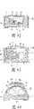
图3表示实施方式B-1,图3(a)是剖面简图,图3(b)是图3(a)的主要部分放大图。Fig. 3 shows Embodiment B-1, Fig. 3(a) is a schematic sectional view, and Fig. 3(b) is an enlarged view of main parts of Fig. 3(a).
图4是表示实施方式B-2的剖面简图。Fig. 4 is a schematic sectional view showing Embodiment B-2.
图5是表示实施方式B-3的剖面简图。Fig. 5 is a schematic sectional view showing Embodiment B-3.
图6是表示实施方式B-4的剖面简图。Fig. 6 is a schematic sectional view showing Embodiment B-4.
图7是表示实施方式B-5的剖面简图。Fig. 7 is a schematic sectional view showing Embodiment B-5.
图8是表示实施方式B-6的剖面简图。Fig. 8 is a schematic sectional view showing Embodiment B-6.
图9是表示实施方式B-7的剖面简图。Fig. 9 is a schematic sectional view showing Embodiment B-7.
图10是表示实施方式B-8的剖面简图。Fig. 10 is a schematic sectional view showing Embodiment B-8.
图11是表示实施方式B-9的剖面简图。Fig. 11 is a schematic sectional view showing Embodiment B-9.
图12是表示实施方式B-10的剖面简图。Fig. 12 is a schematic sectional view showing Embodiment B-10.
图13是表示实施方式B-11的剖面简图。Fig. 13 is a schematic sectional view showing Embodiment B-11.
图14是表示实施方式B-12的剖面简图。Fig. 14 is a schematic sectional view showing Embodiment B-12.
图15是表示实施方式B-13的剖面简图。Fig. 15 is a schematic sectional view showing Embodiment B-13.
图16是表示实施方式B-14的剖面简图。Fig. 16 is a schematic sectional view showing Embodiment B-14.
图17是表示实施方式B-15的剖面简图。Fig. 17 is a schematic sectional view showing Embodiment B-15.
图18是表示实施方式B-16的剖面简图。Fig. 18 is a schematic sectional view showing Embodiment B-16.
图19是表示实施方式B-17的剖面简图。Fig. 19 is a schematic sectional view showing Embodiment B-17.
图20是表示实施方式B-18的剖面简图。Fig. 20 is a schematic sectional view showing Embodiment B-18.
图21是表示实施方式B-19的剖面简图。Fig. 21 is a schematic sectional view showing Embodiment B-19.
图22是表示实施方式B-20的剖面简图。Fig. 22 is a schematic sectional view showing Embodiment B-20.
图23是表示实施方式B-21的剖面简图。Fig. 23 is a schematic sectional view showing Embodiment B-21.
图24是表示实施方式B-21的主要部分剖面图。Fig. 24 is a sectional view of main parts showing Embodiment B-21.
图25是表示实施方式B-22的剖面简图。Fig. 25 is a schematic sectional view showing Embodiment B-22.
图26是表示实施方式B-22的主要部分剖面图。Fig. 26 is a sectional view of main parts showing Embodiment B-22.
图27是表示实施方式B-23的剖面简图。Fig. 27 is a schematic sectional view showing Embodiment B-23.
图28是表示实施方式B-23的主要部分立体图。Fig. 28 is a perspective view of main parts showing Embodiment B-23.
图29是表示实施方式B-24的剖面简图。Fig. 29 is a schematic sectional view showing Embodiment B-24.
图30是表示实施方式B-24的主要部分剖面图。Fig. 30 is a sectional view of main parts showing Embodiment B-24.
图31是表示实施方式B-24的主要部分立体图。Fig. 31 is a perspective view of main parts showing Embodiment B-24.
图32是表示实施方式B-25的剖面简图。Fig. 32 is a schematic sectional view showing Embodiment B-25.
图33是表示实施方式B-26的剖面简图。Fig. 33 is a schematic sectional view showing Embodiment B-26.
图34是表示实施方式B-27的剖面简图。Fig. 34 is a schematic sectional view showing Embodiment B-27.
图35是表示实施方式B-28的剖面简图。Fig. 35 is a schematic sectional view showing Embodiment B-28.
图36是表示实施方式B-29的剖面简图。Fig. 36 is a schematic sectional view showing Embodiment B-29.
图37表示实施方式B-30,图37(a)是剖面简图,图37(b)是图37(a)的主要部分放大图。Fig. 37 shows Embodiment B-30, Fig. 37(a) is a schematic sectional view, and Fig. 37(b) is an enlarged view of main parts of Fig. 37(a).
图38是表示实施方式B-31的剖面简图。Fig. 38 is a schematic sectional view showing Embodiment B-31.
图39是表示实施方式B-32的剖面简图。Fig. 39 is a schematic sectional view showing Embodiment B-32.
图40是表示实施方式B-33的剖面简图。Fig. 40 is a schematic sectional view showing Embodiment B-33.
图41是表示实施方式B-34的剖面简图。Fig. 41 is a schematic sectional view showing Embodiment B-34.
图42是表示实施方式B-35的剖面简图。Fig. 42 is a schematic sectional view showing Embodiment B-35.
图43是表示实施方式B-36的剖面简图。Fig. 43 is a schematic sectional view showing Embodiment B-36.
图44是表示实施方式B-37的剖面简图。Fig. 44 is a schematic sectional view showing Embodiment B-37.
图45是表示实施方式B-38的剖面简图。Fig. 45 is a schematic sectional view showing Embodiment B-38.
图46是表示实施方式B-39的剖面简图。Fig. 46 is a schematic sectional view showing Embodiment B-39.
图47是表示实施方式B-40的剖面简图。Fig. 47 is a schematic sectional view showing Embodiment B-40.
图48是各实施方式的主要部分的其它结构例的说明图。FIG. 48 is an explanatory diagram of another structural example of the main part of each embodiment.
图49(a)、图49(b)均是各实施方式的基本概念的说明图。Fig. 49(a) and Fig. 49(b) are both explanatory diagrams of the basic concept of each embodiment.
图50是在本发明的实施例1-1中测定的个体Si-NMR谱。Fig. 50 is an individual Si-NMR spectrum measured in Example 1-1 of the present invention.
图51是在本发明的实施例2-1中测定的个体Si-NMR谱。Fig. 51 is an individual Si-NMR spectrum measured in Example 2-1 of the present invention.
图52是在本发明的实施例2-2中测定的个体Si-NMR谱。Fig. 52 is an individual Si-NMR spectrum measured in Example 2-2 of the present invention.
图53是在本发明的实施例2-3中测定的个体Si-NMR谱。Fig. 53 is an individual Si-NMR spectrum measured in Example 2-3 of the present invention.
图54是在比较例2-1中测定的个体Si-NMR谱。Fig. 54 is an individual Si-NMR spectrum measured in Comparative Example 2-1.
图55是在比较例2-2中测定的个体Si-NMR谱。Fig. 55 is an individual Si-NMR spectrum measured in Comparative Example 2-2.
图56是在比较例2-4中测定的个体Si-NMR谱。Fig. 56 is an individual Si-NMR spectrum measured in Comparative Example 2-4.
符号说明Symbol Description
1、1A、1B发光装置(半导体发光器件);1. 1A, 1B light emitting devices (semiconductor light emitting devices);
2发光元件;2 light-emitting elements;
3A透明部件(半导体器件用部件);3A transparent parts (parts for semiconductor devices);
3B荧光体部(半导体器件用部件);3B phosphor part (parts for semiconductor devices);
4a、4b从发光元件发射的光的一部分;4a, 4b a portion of the light emitted from the light-emitting element;
5荧光体部中所含有的荧光体颗粒、荧光离子、荧光染料等荧光成分所特有的波长的光;5 Light of a wavelength unique to fluorescent components such as phosphor particles, fluorescent ions, and fluorescent dyes contained in the phosphor portion;
11模制部;11 molding department;
12、13引线端子;12, 13 lead terminals;
14反射镜(杯模部);14 reflector (cup mold part);
15导电线;15 conductive wires;
16绝缘基板;16 insulating substrate;
16a凹处;16a recess;
17印刷布线;17 printed wiring;
18框材;18 frame materials;
19密封部;19 sealing part;
19a密封功能部;19a sealing function part;
19b透镜功能部;19b lens function part;
19c凹部;19c recess;
19d贯通孔;19d through hole;
21发光层部;21 light-emitting layer part;
23反射层;23 reflective layer;
24补片(bump);24 patch (bump);
33、34荧光体部;33, 34 phosphor parts;
35固体介质35 solid medium
具体实施方式Detailed ways
下面详细说明本发明,但本发明不限于以下的实施方式,可以在该要点的范围内进行各种变更后实施。The present invention will be described in detail below, but the present invention is not limited to the following embodiments, and can be implemented with various modifications within the scope of the gist.
[I.第一半导体发光器件用部件][I. Part for the first semiconductor light emitting device]
[I-1.第一半导体发光器件用部件的构成][I-1. Configuration of the first semiconductor light emitting device member]
本发明的第一半导体发光器件用部件具有以下的特征(1)~(3)。The first component for a semiconductor light emitting device of the present invention has the following features (1) to (3).
(1)该部件的固体Si-核磁共振谱中具有至少一个选自由(i)和(ii)组成的组中的峰,(1) having at least one peak selected from the group consisting of (i) and (ii) in the solid Si-NMR spectrum of the part,
所述(i)是峰顶的位置位于化学位移为-40ppm~0ppm的区域、半峰宽为0.3ppm~3.0ppm的峰,The (i) is a peak whose peak position is located in the region of -40ppm to 0ppm with a half-width of 0.3ppm to 3.0ppm in chemical shift,
所述(ii)是峰顶的位置位于化学位移为-80ppm以上且小于-40ppm的区域、半峰宽为0.3ppm~5.0ppm的峰;The above (ii) is a peak whose peak position is located in a region where the chemical shift is more than -80ppm and less than -40ppm, and the half-peak width is 0.3ppm to 5.0ppm;
(2)该部件的硅含量为20重量%以上;(2) The silicon content of the part is more than 20% by weight;
(3)该部件的硅烷醇含量为0.1重量%~10重量%。(3) The silanol content of the member is 0.1% by weight to 10% by weight.
下面,首先根据这些特征(1)~(3)进行说明。Hereinafter, first, the description will be made based on these features (1) to (3).
[I-1-1.固体Si-NMR谱][I-1-1. Solid Si-NMR spectrum]
以硅为主成分的化合物采用SiO2·nH2O的示性式表示,在该化合物的结构上,硅原子Si的四面体的各顶点上结合有氧原子O,这些氧原子O进一步与硅原子Si结合,扩展为网状。于是,下面所示的模式图中忽略上述的四面体结构来表示Si-O的网状结构,在Si-O-Si-O-的重复单元中,也存在一部分的氧原子O被其它成员(例如-H、-CH3等)取代的单元,关注于一个硅原子Si时,存在如下述式(A)所示的具有4个-OSi的硅原子Si(Q4)、如下述式(B)所示的具有3个-OSi的硅原子Si(Q3)等。而且,在固体Si-NMR谱测定中,基于上述各硅原子Si的峰依次被称为Q4峰、Q3峰、…。The compound with silicon as the main component is represented by the schematic formula of SiO2 ·nH2 O. In the structure of the compound, oxygen atoms O are bonded to each vertex of the tetrahedron of silicon atom Si, and these oxygen atoms O are further combined with silicon Atomic Si is combined and expanded into a network. Therefore, the above-mentioned tetrahedral structure is ignored in the schematic diagram shown below to represent the network structure of Si-O. In the repeating unit of Si-O-Si-O-, there are also some oxygen atoms O that are replaced by other members ( For example -H,-CH3, etc.) substituted units, when focusing on one silicon atom Si, there are silicon atoms Si(Q4 ) having four -OSi as shown in the following formula (A), such as the following formula (B ) represented by silicon atoms Si(Q3 ) having 3 -OSi, and the like. In addition, in solid Si-NMR spectrum measurement, the peaks based on the above-mentioned silicon atoms Si are called Q4 peak, Q3 peak, . . . in order.


这些结合有4个氧原子的硅原子一般统称为Q部位。本发明中,将来自Q部位的Q0~Q4的各峰称为Qn峰组。经观测,不含有有机取代基的二氧化硅膜的Qn峰组通常是在化学位移为-80ppm~-130ppm的区域连续的多峰性的峰。These silicon atoms bonded with 4 oxygen atoms are generally referred to as Q sites. In the present invention, each peak of Q0 to Q4 originating from the Q site is referred to as a Qn peak group. It has been observed that the Qn peak group of the silicon dioxide film not containing an organic substituent is generally a continuous multimodal peak in the region of the chemical shift of -80 ppm to -130 ppm.
相对于此,结合有3个氧原子、并结合有1个除此之外的原子(通常为碳)的硅原子一般总称为T部位。与Q部位的情况相同,来自T部位的峰作为T0~T3的各峰被观测到。本发明中,将来自T部位的各峰称为Tn峰组。经观测,Tn峰组一般为在比Qn峰组更靠近高磁场侧(通常化学位移为-80ppm~-40ppm)的区域连续的多峰性的峰。On the other hand, a silicon atom to which three oxygen atoms are bonded and one other atom (usually carbon) is bonded is generally referred to as a T site. As in the case of the Q site, peaks derived from the T site were observed as respective peaks from T0 to T3 . In the present invention, each peak derived from the T site is referred to as a Tn peak group. It has been observed that the Tn peak group is generally a continuous multimodal peak in a region closer to the high magnetic field side (usually a chemical shift of -80 ppm to -40 ppm) than the Qn peak group.
此外,结合有2个氧原子并且还结合有2个除此之外的原子(通常为碳)的硅原子一般统称为D部位。与来自Q部位和T部位的峰组相同,来自D部位的峰也作为D0~Dn的各峰(Dn峰组)被观测到,并且经观测其为在比Qn和Tn的峰组更靠近高磁场侧的区域(通常化学位移为0~-40ppm的区域)中的多峰性的峰。这些Dn、Tn、Qn的各峰组的面积之比分别与置于与各峰组相对应的环境中的硅原子的摩尔比相等,因此,将全部峰的面积设为全部硅原子的摩尔量时,Dn峰组以及Tn峰组的合计面积通常与直接键合于与之相对应的碳原子的全部硅的摩尔量相对应。In addition, silicon atoms to which two oxygen atoms are bonded and two other atoms (usually carbon) are also bonded are collectively referred to as D sites. Like the peak group from the Q site and the T site, the peak from the D site is also observed as each peak (Dn peak group) from D0 to Dn , and it is observed that it is in the ratio of Qn and Tn Multimodal peaks in a region where the peak group is closer to the high magnetic field side (usually a region where the chemical shift is 0 to -40 ppm). The ratio of the area of each peak group of these Dn , Tn , and Qn is equal to the molar ratio of the silicon atoms placed in the environment corresponding to each peak group, so the area of all the peaks is assumed to be all silicon atoms The total area of the Dn peak group and the Tn peak group usually corresponds to the molar amount of all silicon directly bonded to the corresponding carbon atoms.
若测定本发明的第一半导体发光器件用部件的固体Si-NMR谱,则在各个不同的区域出现来自与有机基团的碳原子直接结合的硅原子的Dn峰组和Tn峰组、以及来自未与有机基团的碳原子结合的硅原子的Qn峰组。如上所述,这些峰之中,小于-80ppm的峰相当于Qn峰,-80ppm以上的峰相当于Dn、Tn峰。本发明的第一半导体发光器件用部件中,Qn峰不是必须的,但在Dn、Tn峰区域上观测到至少1个、优选多个峰。When the solid-state Si-NMR spectrum of the first semiconductor light-emitting device member of the present invention is measured, aDn peak group anda Tn peak group derived from the silicon atom directly bonded to the carbon atom of the organic group appear in different regions, and the group of Qn peaks from silicon atoms not bonded to carbon atoms of organic groups. As mentioned above, among these peaks, the peak less than -80 ppm corresponds to the Qn peak, and the peak above -80 ppm corresponds to the Dn and Tn peaks. In the first semiconductor light-emitting device member of the present invention, theQn peak is not essential, but at least one, preferably a plurality of peaks are observed in theDn andTn peak regions.
另外,半导体发光器件用部件的化学位移值例如可采用下述方法进行固体Si-NMR谱测定并根据测定结果进行计算。并且,测定数据的解析(半值宽度或硅烷醇量解析)可以通过例如使用高斯函数或洛伦茨函数的波形分离解析等将各峰分割提取的方法来进行。In addition, the chemical shift value of the semiconductor light-emitting device member can be measured by solid Si-NMR spectrum using the following method, for example, and can be calculated from the measurement result. Furthermore, the analysis of the measurement data (half-value width or silanol amount analysis) can be performed by, for example, a method of segmenting and extracting each peak, such as waveform separation analysis using a Gaussian function or a Lorenz function.
[固体Si-NMR谱测定以及硅烷醇含量的计算][Measurement of solid Si-NMR spectrum and calculation of silanol content]
对半导体发光器件用部件测定固体Si-NMR谱时,在以下的条件下进行固体Si-NMR谱测定以及波形分离解析。并且,根据得到的波形数据,求出半导体发光器件用部件的各半峰宽。并且,根据来自硅烷醇的峰面积与全部峰面积的比例,求出成为硅烷醇的硅原子与全部硅原子的比例(%),分别与分析出的硅含量进行比较,从而求出硅烷醇含量。When measuring the solid Si-NMR spectrum of the member for a semiconductor light emitting device, the solid Si-NMR spectrum measurement and waveform separation analysis are performed under the following conditions. And, based on the obtained waveform data, each half-value width of the semiconductor light emitting device member was obtained. And, from the ratio of the peak area derived from silanol to the total peak area, the ratio (%) of silicon atoms that become silanols to all silicon atoms is obtained, and the silanol content is obtained by comparing each with the analyzed silicon content. .
<装置条件><Device Conditions>
装置:Chemagnetics公司Infinity CMX-400核磁共振分光装置Device: Infinity CMX-400 nuclear magnetic resonance spectroscopic device of Chemagnetics
29Si共振频率:79.436MHz29 Si resonance frequency: 79.436MHz
探针:7.5mmФCP/MAS用探针Probe: 7.5mmФCP/MAS probe
测定温度:室温Measurement temperature: room temperature
试样旋转数:4kHzSample rotation number: 4kHz
测定法:单脉冲法Determination method: single pulse method
1H去耦频率:50kHz1 H decoupling frequency: 50kHz
29Si触发角:90°29 Si firing angle: 90°
29Si90°脉冲宽度:5.0μs29 Si90°pulse width: 5.0μs
重复时间:600sRepeat time: 600s
累计次数:128次Cumulative times: 128 times
观测宽度:30kHzObservation width: 30kHz
展宽因子(Broadening factor):20HzBroadening factor: 20Hz
<数据处理法><Data processing method>
对于半导体发光器件用部件,读取512点作为测定数据,对8192点进行零填充(zero filling),进行傅立叶变换。For semiconductor light-emitting device components, 512 points were read as measurement data, zero filling was performed on 8192 points, and Fourier transform was performed.
<波形分离解析法><Waveform Separation Analysis Method>
对于傅立叶变换后的波谱的各峰,将通过洛伦茨波形和高斯波形或这两种波形的混合而得到的峰形状的中心位置、高度、半值宽度设为可变参数,通过非线性最小二乘法进行最佳化计算。For each peak of the spectrum after Fourier transform, the center position, height, and half-value width of the peak shape obtained by the Lorenz waveform and the Gaussian waveform or a mixture of these two waveforms are set as variable parameters, and the non-linear minimum The optimization calculation was performed by the quadratic method.
另外,峰的鉴定参考AIChE Journal,44(5),p.1141,1998年等。In addition, the identification of the peak refers to AIChE Journal, 44(5), p.1141, 1998, etc.
[I-1-2.硅含量][I-1-2. Silicon content]
本发明的第一半导体发光器件用部件中硅含量必须为20重量%以上(特征(2))。现有的半导体发光器件用部件的基本骨架是以碳-碳以及碳-氧键为基本骨架的环氧树脂等有机树脂。相对于此,本发明的第一半导体发光器件用部件的基本骨架是与玻璃(硅酸盐玻璃)等相同的无机质的硅氧烷键。如下述表1的化学键的比较表可知,该硅氧烷键具有如下的作为半导体发光器件用部件的优异特征。The silicon content in the first semiconductor light emitting device member of the present invention must be 20% by weight or more (feature (2)). The basic skeleton of existing components for semiconductor light emitting devices is organic resin such as epoxy resin with carbon-carbon and carbon-oxygen bonds as the basic skeleton. In contrast, the basic skeleton of the first semiconductor light emitting device member of the present invention is an inorganic siloxane bond similar to that of glass (silicate glass). As can be seen from the comparison table of chemical bonds in Table 1 below, this siloxane bond has the following excellent characteristics as a member for a semiconductor light emitting device.
(I)键能大,难以进行热分解/光分解,所以耐光性良好。(I) Since the bond energy is large and thermal decomposition/photolysis is difficult, light resistance is good.
(II)电气上若干分极。(II) Several poles electrically.
(III)链状结构的自由度大,可以是可挠性大的结构,可以在硅氧烷链中心自由旋转。(III) The chain structure has a large degree of freedom and can be a highly flexible structure that can freely rotate at the center of the siloxane chain.
(IV)氧化度大,不会被进一步氧化。(IV) The degree of oxidation is large and will not be further oxidized.
(V)电绝缘性强。(V) Strong electrical insulation.
表1化学键比较表Table 1 Chemical bond comparison table
根据这些特征,可以理解,与环氧树脂等现有的树脂类半导体发光器件用部件不同,硅氧烷键为三维结构,并且以高交联度结合的骨架所形成的硅酮类半导体发光器件用部件接近于玻璃或岩石等无机质,可以形成耐热性/耐光性优异的保护被膜。尤其是取代基为甲基的硅酮类半导体发光器件用部件在紫外区域不具有吸收性,因此,不易引起光分解,耐光性优异。From these characteristics, it can be understood that, unlike conventional components for resin-based semiconductor light-emitting devices such as epoxy resins, siloxane bonds have a three-dimensional structure, and a silicone-based semiconductor light-emitting device formed of a skeleton bonded with a high degree of crosslinking By using parts close to inorganic substances such as glass and rock, a protective film with excellent heat resistance and light resistance can be formed. In particular, silicone-based semiconductor light-emitting device members whose substituents are methyl groups do not have absorption in the ultraviolet region, and therefore are less prone to photodecomposition and have excellent light resistance.
本发明的第一半导体发光器件用部件的硅含量如上所述为20重量%以上,其中优选为25重量%以上,更优选为30重量%以上。另一方面,作为硅含量的上限,仅由SiO2构成的玻璃中的硅含量为47重量%,因而通常为47重量%以下的范围。The silicon content of the first member for a semiconductor light emitting device of the present invention is 20% by weight or more as described above, preferably 25% by weight or more, and more preferably 30% by weight or more. On the other hand, as the upper limit of the silicon content, the silicon content in glass consisting only of SiO2 is 47% by weight, so it is usually in the range of 47% by weight or less.
另外,例如可以使用如下方法,进行电感耦合高频等离子体分光(inductivelycoupled plasma spectrometry,下面适当简称为“ICP”)分析,根据其结果计算出半导体发光器件用部件的硅含量。In addition, for example, the following method can be used to conduct inductively coupled plasma spectrometry (hereinafter referred to as "ICP" as appropriate) analysis, and calculate the silicon content of the semiconductor light emitting device component based on the result.
[硅含量的测定][Determination of silicon content]
将单独的半导体发光器件用部件的固化物粉碎成100μm左右,在铂坩锅中于大气中、450℃下烧制1小时,接着在750℃下烧制1小时,在950℃下烧制1.5小时,除去碳成分之后,在得到的少量残渣中加入10倍量以上的碳酸钠,利用燃烧器进行加热,使混合物熔融,将混合物冷却,加入脱盐水,进一步利用盐酸将pH调整到中性左右,同时按照硅达到几ppm的程度进行定容,进行ICP分析。The cured product of individual components for semiconductor light emitting devices is pulverized to about 100 μm, fired in the air in a platinum crucible at 450°C for 1 hour, then fired at 750°C for 1 hour, and fired at 950°C for 1.5 hour, after removing the carbon component, add more than 10 times the amount of sodium carbonate to the obtained small amount of residue, heat the mixture with a burner, cool the mixture, add desalted water, and further adjust the pH to about neutral with hydrochloric acid , and at the same time carry out constant volume according to the degree of silicon reaching several ppm, and carry out ICP analysis.
[I-1-3.硅烷醇含量][I-1-3. Silanol content]
本发明的第一半导体发光器件用部件中,硅烷醇含量处于通常为0.1重量%以上、优选为0.3重量%以上、并且通常为10重量%以下、优选为8重量%以下、更优选为5重量%以下的范围(特征(3))。In the first member for a semiconductor light emitting device of the present invention, the silanol content is usually 0.1% by weight or more, preferably 0.3% by weight or more, and usually 10% by weight or less, preferably 8% by weight or less, more preferably 5% by weight The range below % (feature (3)).
通常,对于采用烷氧基硅烷作为原料通过溶胶-凝胶法所得到的玻璃体,在150℃、3小时左右的温和的固化条件下不会完全聚合成为氧化物,硅烷醇会有一定量的残留。仅由四烷氧基硅烷得到的玻璃体具有高硬度-高耐光性,但交联度高,所以分子链的自由度小,不会发生完全的缩合,因而硅烷醇的残留量多。并且,干燥固化水解-缩合液时,交联点多,所以快速变浓,干燥和固化同时进行,因此,成为具有较大应变的块状体(bulk)。若将这样的部件用作半导体发光器件用部件,则长期使用时会因残留硅烷醇的缩合而产生新的内部应力,容易发生裂纹和剥离、断线等问题。而且,部件的断裂面上硅烷醇更多,透湿性小,所以表面吸湿性高,容易招来水分的渗入。虽然可以通过400℃以上的高温烧制来降低硅烷醇含量,但半导体发光器件的耐热性大部分为260℃以下,因而该高温烧制难以实现。Usually, for the glass body obtained by the sol-gel method using alkoxysilane as a raw material, it will not be completely polymerized into oxides under the mild curing conditions of 150°C and about 3 hours, and a certain amount of silanol will remain. The glass body obtained only from tetraalkoxysilane has high hardness and high light resistance, but the degree of crosslinking is high, so the degree of freedom of the molecular chain is small, and complete condensation does not occur, so the residual amount of silanol is large. In addition, when the hydrolysis-condensation liquid is dried and solidified, there are many cross-linking points, so it quickly becomes concentrated, and drying and curing proceed simultaneously, so it becomes a bulk with a large strain. If such a member is used as a member for a semiconductor light-emitting device, new internal stress will be generated due to condensation of residual silanol during long-term use, and problems such as cracks, peeling, and disconnection will easily occur. Moreover, there are more silanols on the fractured surface of the component, and the moisture permeability is low, so the surface is highly hygroscopic and easily attracts the infiltration of moisture. Although the silanol content can be reduced by firing at a high temperature above 400°C, most of the heat resistance of semiconductor light emitting devices is below 260°C, so this high-temperature firing is difficult to achieve.
另一方面,本发明的第一半导体发光器件用部件中硅烷醇含量低,所以具有经时变化小、长期的性能稳定性优异、吸湿性和透湿性低的优异性能。但是,完全不含硅烷醇的部件与半导体发光器件的密合性差,因此,本发明的第一半导体发光器件用部件中硅烷醇含量处于如上所述的最佳范围。On the other hand, the first member for semiconductor light-emitting device of the present invention has excellent properties such as small change over time, excellent long-term performance stability, and low moisture absorption and moisture permeability because of its low silanol content. However, a member completely free of silanol has poor adhesion to a semiconductor light emitting device. Therefore, the silanol content in the first member for a semiconductor light emitting device of the present invention is within the optimum range as described above.
另外,半导体发光器件用部件的硅烷醇含量可以采用如下方式计算:使用例如[I-1-1.固体Si-NMR谱]的[固体Si-NMR谱测定以及硅烷醇含量的计算]中说明的方法,进行固体Si-NMR谱测定,根据来自硅烷醇的峰面积与全部峰面积之比求出形成为硅烷醇的硅原子在全部硅原子中的比例(%),与另外分析的硅含量进行比较,由此计算出半导体发光器件用部件的硅烷醇含量。In addition, the silanol content of the components for semiconductor light-emitting devices can be calculated as follows: using, for example, the method described in [I-1-1. Solid Si-NMR Spectrum] [Measurement of Solid Si-NMR Spectrum and Calculation of Silanol Content] Method, perform solid Si-NMR spectrum measurement, calculate the proportion (%) of silicon atoms formed as silanols in all silicon atoms according to the ratio of the peak area derived from silanol to the total peak area, and compare with the silicon content analyzed separately By comparison, the silanol content of the member for semiconductor light-emitting device was calculated from this.
[I-1-4.通过上述特征(1)~(3)得到本发明效果的理由][I-1-4. Reasons for obtaining the effects of the present invention by the above features (1) to (3)]
本发明的第一半导体发光器件用部件具备上述(1)~(3)的特征,因而即使在厚膜部分也不会产生裂纹,可致密地固化,与壳体的密合性/芯片密封特性优异,能够得到固化后对光/热的耐久性优异的固化物。其理由并不确定,推测如下。The first component for a semiconductor light-emitting device of the present invention has the above-mentioned features (1) to (3), so no cracks are generated even in the thick film portion, it can be solidified densely, and it has adhesiveness to the case/chip sealing property It is excellent and can obtain a cured product excellent in light/heat durability after curing. The reason for this is not certain, but it is presumed as follows.
作为得到含有无机玻璃的半导体发光器件用部件的方法,可以举出熔融法和溶胶-凝胶法,在所述熔融法中,将低融点玻璃熔融来进行密封,在所述溶胶-凝胶法中,在较低温度下涂布对烷氧基硅烷等进行水解-缩聚而得到的液体,进行干燥固化。其中,由熔融法得到的部件大体上仅观测到Qn峰,而熔融需要至少350℃以上的高温,致使半导体发光器件发生热劣化,所以不是现实的方法。As a method of obtaining a component for a semiconductor light-emitting device containing inorganic glass, a melting method and a sol-gel method are mentioned. In the process, the liquid obtained by hydrolyzing and polycondensing alkoxysilane etc. is applied at a relatively low temperature, and dried and solidified. Among them, only the Qn peak is generally observed in parts obtained by the melting method, but melting requires a high temperature of at least 350° C., which causes thermal degradation of the semiconductor light emitting device, so it is not a practical method.
另一方面,在溶胶-凝胶法中,由4官能的硅烷化合物得到的水解-缩聚产物形成完全无机的玻璃,耐热/耐候性极其优异,但固化反应是通过硅烷醇的缩合(脱水/脱醇)反应来进行交联,所以将伴随脱水所致的重量减少、体积收缩。因此,若仅由具有Qn峰的4官能的硅烷构成原料,则固化收缩的程度会过大,被膜上容易产生裂纹,不能进行厚膜化。在这样的体系中,尝试通过添加作为骨材的无机颗粒或通过再涂装来增加膜厚,但一般膜厚极限为10μm左右。将溶胶-凝胶玻璃用作半导体发光器件用部件时,需要在复杂形状的布线部分上制模,因此,存在必须要确保膜厚达到500μm~1000μm的问题。并且,如上所述,为了充分减少残留的硅烷醇、得到完全无机的玻璃,需要加热到400℃以上的高温,致使半导体器件热劣化,所以并不现实。On the other hand, in the sol-gel method, the hydrolysis-polycondensation product obtained from a tetrafunctional silane compound forms a completely inorganic glass, which is extremely excellent in heat resistance/weather resistance, but the curing reaction is through the condensation of silanol (dehydration/ Dealcoholation) reaction to carry out crosslinking, so it will be accompanied by weight loss and volume shrinkage caused by dehydration. Therefore, if the raw material is composed of only tetrafunctional silane having a Qn peak, the degree of curing shrinkage will be too large, cracks will easily occur in the film, and it will not be possible to increase the thickness of the film. In such a system, attempts are made to increase the film thickness by adding inorganic particles as aggregates or by recoating, but the general film thickness limit is about 10 μm. When sol-gel glass is used as a component for a semiconductor light-emitting device, it is necessary to form a mold on a wiring part having a complicated shape, so there is a problem that a film thickness of 500 μm to 1000 μm must be ensured. In addition, as described above, in order to sufficiently reduce the remaining silanol and obtain a completely inorganic glass, it is necessary to heat to a high temperature of 400° C. or higher, which causes thermal degradation of the semiconductor device, so it is not practical.
相对于此,本发明的第一半导体发光器件用部件中,为了调整交联密度、使膜具有可挠性,导入具有Tn峰的3官能硅烷和/或具有Dn峰的2官能硅烷,同时进行水解-缩聚,从而可在不对功能造成防碍的范围内适当减少脱水缩合所致的体积减少量以及交联密度,并且,通过控制水解-缩合工序以及干燥工序,能够得到膜厚达到1000μm的透明玻璃膜状或透明弹性体状的部件。因此,在本发明的第一半导体发光器件用部件中,必须具有在-80ppm以上观测到的Tn峰和/或Dn峰。On the other hand, in the first semiconductor light emitting device member of the present invention, in order to adjust the crosslink density and make the film flexible, a trifunctional silane having aTn peak and/or a bifunctional silane having aDn peak are introduced, Simultaneous hydrolysis and polycondensation can appropriately reduce volume loss and crosslinking density due to dehydration condensation within the range that does not hinder the function, and by controlling the hydrolysis-condensation process and drying process, a film thickness of 1000 μm can be obtained. Transparent glass film-like or transparent elastomer-like parts. Therefore, in the first component for a semiconductor light emitting device of the present invention, it is necessary to have a Tn peak and/or a Dn peak observed at -80 ppm or more.
作为这样的以2官能或3官能的原料为主成分进行厚膜化的方法,已知有例如眼镜等硬涂膜的技术,其膜厚为数微米以下。在这些硬涂膜中,膜厚较薄,所以溶剂容易挥发,可以均匀地固化,与基材的密合性以及线膨胀系数的差异是裂纹的主要原因。相对于此,对于本发明的第一半导体发光器件用部件,膜厚如涂料一般厚,所以膜自身具有某种程度的强度,可以吸收线膨胀系数细微的差异,但是,溶剂干燥导致体积减少,因此存在不同于薄膜情况中的产生内部应力的新问题。即,对LED的杯模等开口面积窄的深式容器进行模制时,若在膜深部的干燥不充分的状态下进行加热固化,则交联后引起溶剂挥发,体积减少,因此,产生大的裂纹或发泡。这样的膜上存在较大的内部应力,若测定该膜的固体Si-NMR谱,则与内部应力小的情况相比,检测到的Dn、Tn、Qn峰组在硅氧烷键角上出现分布,分别为更宽的峰。该情况意味着以2个-OSi所表示的键角相对于Si的应变增大。即,即使是由相同原料形成的膜,它们的半峰宽越窄,越难以产生裂纹,能够形成高质量的膜。As a method of thickening such a film using a bifunctional or trifunctional raw material as a main component, for example, a technique of a hard coat film such as eyeglasses is known, and the film thickness thereof is several micrometers or less. In these hard coating films, the film thickness is thin, so the solvent is easy to volatilize and can be cured uniformly, and the adhesion to the base material and the difference in linear expansion coefficient are the main causes of cracks. On the other hand, in the first semiconductor light emitting device member of the present invention, the film thickness is as thick as paint, so the film itself has a certain degree of strength and can absorb slight differences in the linear expansion coefficient, but the volume decreases due to the drying of the solvent. There is thus a new problem of generating internal stress different from that in the thin film case. That is, when molding a deep container with a narrow opening area such as an LED cup mold, if the deep part of the film is heated and cured without sufficient drying, the solvent will volatilize after cross-linking and the volume will decrease. cracks or blisters. There is a large internal stress on such a film. If the solid Si-NMR spectrum of the film is measured, compared with the case where the internal stress is small, the detected Dn , Tn , and Qn peak groups are at the siloxane bond. Distributions appear on the corners, respectively, as broader peaks. This means that the bond angle represented by two -OSi increases with respect to the strain of Si. That is, even for films formed of the same raw material, the narrower their half widths are, the less likely they are to be cracked, and a high-quality film can be formed.
另外,Si原子的分子运动的约束程度越大,则越容易观测到半值宽度根据应变增大的现象,其显现容易度为Dn<Tn<Qn。In addition, the greater the degree of restraint of the molecular motion of Si atoms, the easier it is to observe the phenomenon that the half-value width increases according to the strain, and the ease of expression is Dn <Tn <Qn .
本发明的第一半导体发光器件用部件的特征在于,在-80ppm以上的区域观测到的半峰宽比已知采用目前的溶胶-凝胶法的半导体发光器件用部件的半值宽度范围小(窄)。The first component for semiconductor light-emitting devices of the present invention is characterized in that the half-value width observed in the region of -80 ppm or more is smaller than the half-value range of components for semiconductor light-emitting devices using the known sol-gel method ( narrow).
若对每个化学位移进行整理,则在本发明的第一半导体发光器件用部件中,在-80ppm以上且小于-40ppm的区域观测到峰顶位置的、Tn峰组的半值宽度处于通常为5.0ppm以下、优选为4.0ppm以下、并且通常为0.3ppm以上、优选为0.4ppm以上的范围。When the individual chemical shifts are sorted out, in the first semiconductor light emitting device member of the present invention, the half value width of theTn peak group at which the peak top position is observed in the region of -80 ppm or more and less than -40 ppm is in the normal range. It is 5.0 ppm or less, preferably 4.0 ppm or less, and usually 0.3 ppm or more, preferably 0.4 ppm or more.
同样地,由于分子运动的约束减小,所以在-40ppm~0ppm的区域观测到峰顶位置的Dn峰组的半值宽度整体小于Tn峰组的情况,处于通常为3.0ppm以下、优选为2.0ppm以下、并且通常为0.3ppm以上的范围。Similarly, since the constraints of molecular motion are reduced, the half-value width of theDn peak group at the peak position observed in the region of -40ppm to 0ppm is generally smaller than the situation of theTn peak group, which is usually 3.0ppm or less, preferably The range is 2.0 ppm or less, and usually 0.3 ppm or more.
若在上述的化学位移区域中观测到的峰的半值宽度大于上述范围,则分子运动的约束增大,处于应变较大的状态,容易产生裂纹,有可能形成耐热/耐候耐久性差的部件。例如,在使用了大量的四官能硅烷的情况下或在干燥工序中进行快速干燥而处于积蓄了大的内部应力的状态下等情况中,半值宽度范围大于上述范围。If the half-value width of the peak observed in the above-mentioned chemical shift region is larger than the above-mentioned range, the constraints on molecular motion will be increased, and the state will be in a state of large strain, which will easily cause cracks and may result in parts with poor heat resistance and weather resistance. . For example, when a large amount of tetrafunctional silane is used, or when a large internal stress is accumulated due to rapid drying in a drying step, the half-value width range is larger than the above-mentioned range.
并且,当半峰宽小于上述范围时,处于该环境的Si原子不参与硅氧烷交联,三官能硅烷例如以未交联状态残留等,由硅氧烷键主体所形成的物质有可能形成耐热/耐候耐久性差的部件。In addition, when the half-peak width is less than the above-mentioned range, the Si atom in this environment does not participate in the crosslinking of siloxane, and trifunctional silane, for example, remains in an uncrosslinked state, and the substance formed by the main body of the siloxane bond may be formed. Parts with poor heat/weather durability.
此外,如上所述,在本发明的第一半导体发光器件用部件的固体Si-核磁共振谱中,Dn、Tn峰区域上观测到至少1个、优选多个峰。因此,本发明的第一半导体发光器件用部件的固体Si-核磁共振谱优选含有至少1个、优选2个以上的选自由具有上述范围的半值宽度的Dn峰组以及Tn峰组组成的组中的峰。In addition, as described above, in the solid-state Si-NMR spectrum of the first semiconductor light emitting device member of the present invention, at least one, preferably a plurality of peaks are observed in the Dn and Tn peak regions. Therefore, the solid-state Si-NMR spectrum of the first semiconductor light-emitting device component of the present invention preferably contains at least one, preferably two or more, selected from the group consisting of theDn peak group and theTn peak group having a half-value width within the above-mentioned range. peaks in the group.
另外,本发明的第一半导体发光器件用部件的组成限于体系内的交联主要是由以二氧化硅为首的无机成分所形成的情况。即,在大量的有机成分中含有少量Si成分的半导体发光器件用部件中,即使在-80ppm以上确认到上述的半值宽度范围的峰,也不能得到本发明的第一半导体发光器件用部件的说明中所规定的良好的耐热/耐光性以及涂布性能。另外,本发明的第一半导体发光器件用部件的说明中所规定的硅含量为20重量%以上的半导体发光器件用部件含有以二氧化硅(SiO2)换算为43重量%以上的SiO2。In addition, the composition of the first semiconductor light emitting device member of the present invention is limited to the case where the crosslinking in the system is mainly formed by inorganic components including silica. That is, in a component for a semiconductor light emitting device containing a small amount of Si component in a large amount of organic components, even if the above-mentioned peak in the half-value width range is confirmed at -80 ppm or more, the first component for a semiconductor light emitting device of the present invention cannot be obtained. Good heat/light resistance and coating properties as specified in the specification. Further, the semiconductor light emitting device member having a silicon content of 20% by weight or more specified in the description of the first member for semiconductor light emitting device of the present invention contains SiO2 at 43% by weight or more in terms of silicon dioxide (SiO2 ).
并且,若本发明的第一半导体发光器件用部件含有适当量的硅烷醇,则硅烷醇与存在于器件表面的极性部分形成氢键,实现密合性。作为极性部分,可以举出例如羟基或金属-氧-金属键(metalloxane bond)的氧等。Furthermore, when the first member for a semiconductor light-emitting device of the present invention contains an appropriate amount of silanol, the silanol forms a hydrogen bond with a polar moiety present on the device surface to achieve adhesion. As the polar moiety, for example, a hydroxyl group or oxygen of a metal-oxygen-metal bond (metalloxane bond), etc. can be mentioned.
而且,本发明的第一半导体发光器件用部件通过在适当的催化剂的存在下加热,从而与器件表面的羟基之间发生脱水缩合,形成共价键,能够进一步实现强固的密合性。Furthermore, the first member for a semiconductor light emitting device of the present invention can dehydrate and condense with hydroxyl groups on the surface of the device by heating in the presence of a suitable catalyst to form a covalent bond, thereby realizing further strong adhesion.
另一方面,若硅烷醇过多,则体系内增粘,难以涂布,或者活性增高,在轻沸点成分挥发之前就由于加热而固化,从而产生发泡或内部应力增大,有可能引发裂纹等。On the other hand, if there is too much silanol, the viscosity in the system will increase, it will be difficult to coat, or the activity will increase, and it will be cured by heating before the light boiling point components are volatilized, resulting in foaming or increased internal stress, which may cause cracks wait.
[I-1-5.硬度测定值][I-1-5. Hardness measured value]
本发明的第一半导体发光器件用部件优选为呈弹性体状的部件。具体地说,A型硬度计测定的硬度测定值(肖氏A)通常为5以上、优选为7以上、更优选为10以上、并且通常为90以下、优选为80以下、更优选为70以下(特征(4))。通过具有上述范围的硬度测定值,本发明的第一半导体发光器件用部件难以产生裂纹,耐回流焊接性(Reflow-Resistance)以及耐温度循环性优异。The first member for a semiconductor light emitting device of the present invention is preferably an elastic member. Specifically, the measured hardness value (Shore A) measured by a type A durometer is usually 5 or more, preferably 7 or more, more preferably 10 or more, and usually 90 or less, preferably 80 or less, more preferably 70 or less (feature (4)). With the measured hardness value in the above range, the first semiconductor light emitting device member of the present invention is less likely to be cracked and has excellent reflow-resistance and temperature cycle resistance.
另外,上述的硬度测定值(肖氏A)可以采用JIS K6253中记载的方法测定。具体地说,可以使用古里精机制作所生产的A型橡胶硬度计进行测定。In addition, the above-mentioned hardness measurement value (Shore A) can be measured by the method described in JIS K6253. Specifically, it can be measured using a rubber hardness tester type A manufactured by Furusei Seiki Seisakusho.
如上所述,本发明的第一半导体发光器件用部件优选具有规定的硬度测定值(肖氏A)。即,本发明的第一半导体发光器件用部件优选呈现为交联密度得到了调整的弹性体状。半导体发光器件中使用多个热膨胀系数不同的部件,如上所述,通过呈现为弹性体状,本发明的第一半导体发光器件用部件能够缓和由于上述各部件的伸缩而产生的应力。即,本发明的第一半导体发光器件用部件的内部应力较少。因此,使用中不易产生剥离、裂纹、断线等,能够提供耐回流焊接性以及耐温度循环性优异的半导体发光器件。As described above, the first component for a semiconductor light emitting device of the present invention preferably has a predetermined measured hardness value (Shore A). That is, the first member for a semiconductor light emitting device of the present invention preferably has an elastomeric shape with adjusted crosslinking density. A semiconductor light emitting device uses a plurality of members having different coefficients of thermal expansion. As described above, the first member for a semiconductor light emitting device of the present invention can relax stress caused by expansion and contraction of each member by being in the form of an elastic body. That is, the first component for a semiconductor light emitting device of the present invention has less internal stress. Therefore, peeling, cracks, disconnection, etc. are less likely to occur during use, and a semiconductor light emitting device excellent in reflow resistance and temperature cycle resistance can be provided.
另外,此处回流焊接(reflow)是指将焊锡膏印刷到基板,在焊锡膏上安装部件后进行加热、接合的焊接方法。而且,耐回流焊接性是指能够抵抗最高温度为260℃、时间为10秒钟的热冲击的性质。In addition, reflow soldering (reflow) here refers to the soldering method which prints solder paste on a board|substrate, mounts a component on a solder paste, and heats and joins. Furthermore, the reflow soldering resistance refers to the property of being able to resist thermal shock at a maximum temperature of 260° C. for 10 seconds.
现有的无机类密封剂非常脆,不能追随半导体发光器件中使用的热膨胀系数不同的各部件的热膨胀/热收缩,存在使用中发生很多剥离、裂纹或断线的问题,还未得到耐回流焊接性、耐温度循环性优异的密封剂。但是,根据本发明的第一半导体发光器件用部件,能够提供如上所述耐回流焊接性以及耐温度循环性优异的半导体发光器件。Existing inorganic sealants are very brittle and cannot follow the thermal expansion/contraction of components with different thermal expansion coefficients used in semiconductor light-emitting devices. There are many problems of peeling, cracking or disconnection during use, and reflow resistance has not yet been obtained. A sealant with excellent durability and temperature cycle resistance. However, according to the first component for semiconductor light emitting device of the present invention, it is possible to provide a semiconductor light emitting device excellent in reflow resistance and temperature cycle resistance as described above.
[I-1-6.峰面积比][I-1-6. Peak area ratio]
本发明的第一半导体发光器件用部件优选满足如下条件(4’)。即,本发明的第一半导体发光器件用部件优选(4’)在固体Si-核磁共振谱中(化学位移为-40ppm~0ppm的峰的总面积)/(化学位移小于-40ppm的峰的总面积)之比(下面在本发明的第一半导体发光器件用部件的说明中适当称为“本发明的峰面积比”)通常为3以上、优选为5以上、更优选为10以上、并且通常为200以下、优选为100以下、更优选为50以下。The first member for a semiconductor light emitting device of the present invention preferably satisfies the following condition (4'). That is, the first component for a semiconductor light-emitting device of the present invention is preferably (4') in the solid Si-NMR spectrum (total area of peaks with a chemical shift of -40 ppm to 0 ppm)/(total area of peaks with a chemical shift of less than -40 ppm area) ratio (hereinafter appropriately referred to as "the peak area ratio of the present invention" in the description of the first semiconductor light-emitting device member of the present invention) is usually 3 or more, preferably 5 or more, more preferably 10 or more, and usually 200 or less, preferably 100 or less, more preferably 50 or less.
本发明的峰面积比处于上述范围表示在本发明的第一半导体发光器件用部件中,所具有的2官能硅烷(D部位)要多于3官能硅烷(T部位)、4官能硅烷(Q部位)等2官能以上的硅烷。通过像这样含有大量的2官能硅烷,本发明的第一半导体发光器件用部件可以满足条件(4)(呈现为弹性体状),能够缓和应力。The peak area ratio of the present invention within the above range means that in the first semiconductor light emitting device member of the present invention, there are more bifunctional silanes (D sites) than trifunctional silanes (T sites) and tetrafunctional silanes (Q sites). ) and other 2 or more functional silanes. By containing a large amount of bifunctional silane in this way, the first member for a semiconductor light emitting device of the present invention can satisfy condition (4) (appears as an elastomer), and can relax stress.
但是,有时本发明的第一半导体发光器件用部件不满足条件(4’)也呈现出弹性体状。相当于该情况的有例如将硅以外的金属的醇盐等偶联剂用作交联剂来制作本发明的第一半导体发光器件用部件的情况等。用于使本发明的第一半导体发光器件用部件满足条件(4)的方法是任意的,不限于该条件(4’)。However, the first member for a semiconductor light emitting device of the present invention may exhibit an elastic body shape even if the condition (4') is not satisfied. Corresponding to this case is, for example, the case where the first member for a semiconductor light emitting device of the present invention is produced using a coupling agent such as an alkoxide of a metal other than silicon as a crosslinking agent. The method for making the first semiconductor light-emitting device member of the present invention satisfy the condition (4) is arbitrary and is not limited to the condition (4').
[I-1-7.UV透过率][I-1-7. UV transmittance]
本发明的第一半导体发光器件用部件在膜厚为0.5mm时于半导体发光器件的发光波长下的透光率通常为80%以上,其中优选为85%以上,更优选为90%以上。通过各种技术来提高半导体发光器件的光取出效率,但是,若用于封装芯片或保持荧光体的透光性部件的透明度低,则使用了该透光性部件的半导体发光器件的亮度降低,因此,难以得到高亮度的半导体发光器件产品。The light transmittance of the first semiconductor light emitting device member of the present invention at the light emitting wavelength of the semiconductor light emitting device is usually 80% or more, preferably 85% or more, and more preferably 90% or more when the film thickness is 0.5mm. The light extraction efficiency of semiconductor light-emitting devices is improved by various techniques, but if the transparency of the light-transmitting member used to package the chip or hold the phosphor is low, the brightness of the semiconductor light-emitting device using the light-transmitting member will decrease, Therefore, it is difficult to obtain high-brightness semiconductor light-emitting device products.
此处,“半导体发光器件的发光波长”根据半导体发光器件的种类而为不同的值,一般是指通常为300nm以上、优选为350nm以上、并且通常为900nm以下、优选为500nm以下的范围的波长。若该范围波长下的透光率低,则半导体发光器件用部件会吸收光,光取出效率下降,不能得到高亮度的器件。此外,光取出效率下降部分的能量变为热,成为器件热劣化的原因,因而不优选。Here, the "emission wavelength of a semiconductor light emitting device" has different values depending on the type of semiconductor light emitting device, and generally refers to a wavelength in the range of usually 300 nm or more, preferably 350 nm or more, and usually 900 nm or less, preferably 500 nm or less . If the light transmittance at the wavelength in this range is low, the member for semiconductor light emitting device will absorb light, the light extraction efficiency will decrease, and a high luminance device cannot be obtained. In addition, the energy in the lowered light extraction efficiency becomes heat and causes thermal degradation of the device, which is not preferable.
此外,在紫外~蓝色区域(300nm~500nm)中,密封部件容易发生光劣化,所以若在于该区域具有发光波长的半导体发光器件中使用耐久性优异的本发明的第一半导体发光器件用部件,则其效果增大,因而优选。In addition, in the ultraviolet to blue region (300nm to 500nm), the sealing member is prone to photodegradation, so if the first semiconductor light emitting device member of the present invention with excellent durability is used in a semiconductor light emitting device having an emission wavelength in this region , the effect increases, which is preferable.
另外,半导体发光器件用部件的透光率可以通过例如下述方法,使用按膜厚为0.5mm进行成型的表面平滑的单独固化物膜的样品,利用紫外分光光度计测定。In addition, the light transmittance of the semiconductor light emitting device member can be measured with an ultraviolet spectrophotometer using, for example, a sample of a single cured product film with a smooth surface and molded to a film thickness of 0.5 mm.
[透光度的测定][Measurement of light transmittance]
采用半导体发光器件用部件的、没有由损伤或凹凸所致的漫反射的厚度为约0.5mm的表面平滑的单独固化物膜,使用紫外分光光度计(岛津制作所制UV-3100),在200nm~800nm的波长下进行透光度测定。Using a component for a semiconductor light emitting device, a thickness of about 0.5 mm of an independent cured product film with a smooth surface without diffuse reflection caused by damage or unevenness, using an ultraviolet spectrophotometer (UV-3100 manufactured by Shimadzu Corporation), in Transmittance measurement is carried out at a wavelength of 200nm to 800nm.
但是,半导体器件的形状各式各样,大多数在超过0.1mm的厚膜状态下使用,但也存在以薄膜使用的用途,例如,在离开LED芯片(发光元件)的位置上设置薄膜状的荧光体层(例如含有纳米荧光体颗粒或荧光离子的厚度为数个微米的层)的情况、在LED芯片的正上方的薄膜上设置高折射光取出膜的情况等。在这样的情况下,优选在该膜厚下显示出80%以上的透过率。即使在这样的薄膜状的应用方式中,本发明的第一半导体发光器件用部件仍显示出优异的耐光性、耐热性,密封性能优异,没有裂纹等,能够稳定地成膜。However, semiconductor devices have various shapes, and most of them are used in the state of thick film exceeding 0.1mm, but there are also applications of using thin film, for example, a thin film is provided at a position away from the LED chip (light emitting element). In the case of a phosphor layer (for example, a layer containing nano-phosphor particles or fluorescent ions with a thickness of several micrometers), in the case of providing a high-refractive light extraction film on a thin film directly above the LED chip, and the like. In such a case, it is preferable to exhibit a transmittance of 80% or more at the film thickness. Even in such a thin film form of application, the first member for a semiconductor light emitting device of the present invention exhibits excellent light resistance and heat resistance, excellent sealing performance, and can be stably formed without cracks.
[I-1-8.其它][I-1-8. Others]
本发明的第一半导体发光器件用部件可以涂布成厚膜状,由于其透明性优异并且密封性、耐热性、耐紫外线性等也优异,所以能够适于用作各种形状的半导体发光器件用部件。特别是能够在发光波长位于蓝~紫外区域的半导体发光器件中用作劣化少的有用的部件。The first component for a semiconductor light emitting device of the present invention can be coated in a thick film, and since it is excellent in transparency, sealability, heat resistance, ultraviolet resistance, etc., it can be suitably used as a semiconductor light emitting device of various shapes. Device parts. In particular, it can be used as a useful member with little degradation in a semiconductor light emitting device whose emission wavelength is in the blue to ultraviolet region.
[I-2.半导体发光器件用部件的制造方法][I-2. Manufacturing method of components for semiconductor light emitting device]
制造本发明的第一半导体发光器件用部件的方法没有特别限定,例如通过对后述的通式(1)或通式(2)所表示的化合物和/或它们的低聚物进行水解-缩聚并对缩聚物(水解-缩聚物)进行干燥即能得到第一半导体发光器件用部件。其中,在本发明的第一半导体发光器件用部件中,若要得到耐久性高的弹性体状半导体发光器件用部件,则优选以硅氧烷键为主体并且降低交联密度。因此,以通式(1)所表示的化合物或低聚物为原料主体,并且优选将以2官能单元为主体的组成物质作为原料主体。并且,像这样将2官能单元作为原料主体时,体系稳定,不易发生凝胶化。因此,该情况下,水解-缩聚物含有溶剂时,在干燥之前,可以事先将溶剂蒸馏除去。The method for producing the first semiconductor light-emitting device member of the present invention is not particularly limited, for example, by performing hydrolysis-polycondensation on compounds represented by general formula (1) or general formula (2) described later and/or their oligomers And drying the polycondensate (hydrolysis-polycondensate) can obtain the first component for semiconductor light emitting device. Among them, in order to obtain a highly durable elastomeric semiconductor light-emitting device member in the first semiconductor light-emitting device member of the present invention, it is preferable to mainly have siloxane bonds and to reduce the crosslinking density. Therefore, the compound or oligomer represented by the general formula (1) is mainly used as a raw material, and preferably a constituent substance mainly composed of a bifunctional unit is used as a main raw material. In addition, when the bifunctional unit is used as the main raw material, the system is stable and gelation is less likely to occur. Therefore, in this case, when the hydrolysis-polycondensation product contains a solvent, the solvent may be distilled off before drying.
下面详细说明该制造方法(适当将其称为“本发明的第一半导体发光器件用部件的制造方法”)。This manufacturing method (it is appropriately referred to as "the first method of manufacturing a semiconductor light-emitting device member of the present invention") will be described in detail below.
[I-2-1.原料][I-2-1. Raw materials]
作为原料,可以使用下述通式(1)所表示的化合物(下面在本发明的第一半导体发光器件用部件的说明中适当称为“化合物(1)”)和/或其低聚物。As a raw material, a compound represented by the following general formula (1) (hereinafter appropriately referred to as "compound (1)" in the description of the first semiconductor light-emitting device member of the present invention) and/or an oligomer thereof can be used.
Mm+XnY1m-n (1)Mm+ Xn Y1mn (1)
通式(1)中,M是选自由硅、铝、锆以及钛组成的组中的至少一种元素。其中优选硅。In the general formula (1), M is at least one element selected from the group consisting of silicon, aluminum, zirconium and titanium. Among them, silicon is preferred.
通式(1)中,m表示M的价数,为1~4的整数。并且“m+”表示m为正价数。In general formula (1), m represents the valence of M and is an integer of 1-4. And "m+" indicates that m is a positive number.
n表示X基的数目,为1~4的整数。其中m≥n。n represents the number of X groups, and is an integer of 1-4. where m≥n.
在通式(1)中,X是可以被溶液中的水或空气中的水分等水解而生成反应性高的羟基的水解性基团,可以任意使用以往公知的基团。例如可以举出C1~C5的低级烷氧基、乙酰氧基、丁酮肟(ブタノキシム)基、氯基等。另外,此处Ci(i为自然数)的标记表示碳原子数为i个。并且,这些水解性基团可以单独使用1种,也可以以任意的组合和比例并用2种以上。In the general formula (1), X is a hydrolyzable group that can be hydrolyzed by water in a solution or moisture in the air to form a highly reactive hydroxyl group, and conventionally known groups can be used arbitrarily. For example, a C1-C5 lower alkoxy group, an acetoxy group, a butanoxime group, a chlorine group, etc. are mentioned. In addition, the notation of Ci (i is a natural number) here indicates that the number of carbon atoms is i. Moreover, these hydrolyzable groups may be used individually by 1 type, and may use 2 or more types together in arbitrary combinations and ratios.
其中,从反应后游离的成分为中性方面考虑,优选C1~C5的低级烷氧基。特别是从反应性高、游离的溶剂为轻沸溶剂的方面考虑,优选甲氧基或乙氧基。Among these, a C1-C5 lower alkoxy group is preferable from the viewpoint that the freed component after the reaction is neutral. In particular, a methoxy group or an ethoxy group is preferable because the reactivity is high and the free solvent is a light boiling solvent.
此外,在通式(1)中,X为乙酰氧基或氯基的情况下,水解反应后乙酸或盐酸游离,因此,用作要求绝缘性的半导体发光器件用部件时,优选增加除去酸成分的工序。In addition, in the general formula (1), when X is an acetoxy group or a chlorine group, acetic acid or hydrochloric acid will be released after the hydrolysis reaction. Therefore, when used as a component for a semiconductor light-emitting device requiring insulation, it is preferable to increase the removal of acid components. process.
在通式(1)中,Y1可以任意选择作为所谓硅烷偶联剂的1价有机基团公知的基团来使用。其中,在本发明的第一半导体发光器件用部件的制造方法中,作为通式(1)中的Y1特别有用的有机基团是指选自下面的Y0所表示的组(有用有机基团组)中的有机基团。此外,为了提高与构成半导体发光器件的其它材料的亲合性和密合性、以及调整半导体发光器件用部件的折射率等,可以适当选择其它有机基团。In the general formula (1), Y1 can be arbitrarily selected and used as a monovalent organic group known as a so-called silane coupling agent. Among them, in the manufacturing method of the first semiconductor light-emitting device component of the present invention, the organic group that is particularly useful as Y in the general formula (1) refers to the group selected from the group representedbyY below (useful organic group group) in the organic group. In addition, other organic groups may be appropriately selected for the purpose of improving the affinity and adhesion with other materials constituting the semiconductor light emitting device, adjusting the refractive index of the semiconductor light emitting device member, and the like.
<有用有机基团组Y0><Useful Organic Group Y0 >
Y0:衍生自脂肪族化合物、脂环式化合物、芳香族化合物、脂肪芳香族化合物的1价以上的有机基团。Y0 : a monovalent or higher organic group derived from an aliphatic compound, an alicyclic compound, an aromatic compound, or an aliphatic aromatic compound.
并且,属于组Y0的有机基团的碳原子数通常为1以上、并且通常为1000以下、优选为500以下、更优选为100以下、进一步优选为50以下。In addition, the number of carbon atoms in the organic group belonging to groupY0 is usually 1 or more, and usually 1,000 or less, preferably 500 or less, more preferably 100 or less, and still more preferably 50 or less.
而且,属于组Y0的有机基团所具有的氢原子中至少一部分可以被下面示例的原子和/或有机官能团等取代基所取代。此时,属于组Y0的有机基团所具有的氢原子之中的多个氢原子可以被下述取代基所取代,这种情况下,可以通过选自下面所示的取代基中的1种或2种以上的组合进行取代。Furthermore, at least a part of the hydrogen atoms contained in the organic group belonging to the group Y0 may be substituted with substituents such as atoms and/or organic functional groups as exemplified below. At this time, among the hydrogen atoms of the organic group belonging to group Y0 , a plurality of hydrogen atoms may be substituted by the following substituents. Substitution of one or a combination of two or more.
作为可以取代属于组Y0的有机基团中的氢原子的取代基的例子,可以举出F、Cl、Br、I等原子;乙烯基、甲基丙烯酰氧基、丙烯酰氧基、苯乙烯基、巯基、环氧基、环氧环己基、环氧丙氧基、氨基、氰基、硝基、磺酸基、羧基、羟基、酰基、烷氧基、亚氨基、苯基等有机官能团等。Examples of substituents that can replace hydrogen atoms in organic groups belonging to groupY0 include atoms such as F, Cl, Br, and I; vinyl, methacryloyloxy, acryloyloxy, benzene Vinyl, mercapto, epoxy, epoxycyclohexyl, glycidoxy, amino, cyano, nitro, sulfonic acid, carboxyl, hydroxyl, acyl, alkoxy, imino, phenyl and other organic functional groups wait.
另外,在上述全部情况下,在可以取代属于组Y0的有机基团中所具有的氢原子的取代基中,对于其中的有机官能团,该有机官能团所具有的氢原子的至少一部分可以被F、Cl、Br、I等卤原子等所取代。In addition, in all the above-mentioned cases, among the substituents that can replace the hydrogen atoms in the organic groups belonging to the group Y0 , for the organic functional groups therein, at least a part of the hydrogen atoms in the organic functional groups can be replaced by F , Cl, Br, I and other halogen atoms, etc. are substituted.
其中,作为可以取代属于组Y0的有机基团中的氢的取代基所示例的基团中,有机官能团是容易导入的基团的一例,可以根据使用目的,导入其它各种具有物理化学功能性的有机官能团。Among the groups exemplified as substituents that can replace the hydrogen in the organic group belonging to the group Y0 , the organic functional group is an example of a group that is easy to introduce, and various other physical and chemical functions can be introduced according to the purpose of use. Sexual organic functional groups.
并且,属于组Y0的有机基团也可以是在基团中具有O、N、或S等各种原子或原子团作为连接基团的有机基团。In addition, the organic group belonging to the group Y0 may be an organic group having various atoms or atomic groups such as O, N, or S as a linking group in the group.
通式(1)中,Y1可以根据其目的从上述的属于有用有机基团组Y0的有机基团等中选择各种基团,从耐紫外线性、耐热性优异的方面考虑,优选以甲基为主体。In the general formula (1),Y1 can be selected from various groups such as organic groups belonging to the above-mentioned useful organic groupY0 according to its purpose, and is preferably from the viewpoint of excellent ultraviolet resistance and heat resistance. Mainly methyl.
作为上述化合物(1)的具体例,对于M为硅的化合物来说,可以举出例如二甲基二甲氧基硅烷、二甲基二乙氧基硅烷、二苯基二甲氧基硅烷、二苯基二乙氧基硅烷、乙烯基三甲氧基硅烷、乙烯基三乙氧基硅烷、乙烯基三乙酰氧基硅烷、γ-氨丙基三甲氧基硅烷、γ-环氧丙氧基丙基三甲氧基硅烷、γ-环氧丙氧基丙基三乙氧基硅烷、β-(3,4-环氧环己基)乙基三甲氧基硅烷、γ-(3,4-环氧环己基)乙基三乙氧基硅烷、γ-(甲基)丙烯酰氧基丙基三甲氧基硅烷、苯基三甲氧基硅烷、苯基三乙酰氧基硅烷、γ-巯基丙基三甲氧基硅烷、γ-氯丙基三甲氧基硅烷、β-氰乙基三乙氧基硅烷、甲基三甲氧基硅烷、甲基三乙氧基硅烷、甲基三丙氧基硅烷、甲基三丁氧基硅烷、乙基三甲氧基硅烷、乙基三乙氧基硅烷、四甲氧基硅烷、四乙氧基硅烷、四丙氧基硅烷、四丁氧基硅烷、二甲基二氯硅烷、二苯基二氯硅烷、甲基苯基二甲氧基硅烷、三甲基甲氧基硅烷、三甲基乙氧基硅烷、三甲基氯硅烷、甲基三氯硅烷、γ-氨丙基三乙氧基硅烷、4-氨丁基三乙氧基硅烷、对氨苯基三甲氧基硅烷、N-(2-氨乙基)-3-氨丙基三甲氧基硅烷、氨乙基氨甲基苯乙基三甲氧基硅烷、3-环氧丙氧基丙基三甲氧基硅烷、2-(3,4-环氧环己基)乙基三甲氧基硅烷、3-氨丙基三甲氧基硅烷、3-氨丙基三乙氧基硅烷、4-氨丁基三乙氧基硅烷、N-(6-氨己基)氨丙基三甲氧基硅烷、3-氯丙基三甲氧基硅烷、3-氯丙基三氯硅烷、(对氯甲基)苯基三甲氧基硅烷、4-氯苯基三甲氧基硅烷、3-甲基丙烯酰氧基丙基三甲氧基硅烷、3-甲基丙烯酰氧基丙基三乙氧基硅烷、3-丙烯酰氧基丙基三甲氧基硅烷、苯乙烯基乙基三甲氧基硅烷、3-巯基丙基三甲氧基硅烷、乙烯基三氯硅烷、乙烯基三(2-甲氧基乙氧基)硅烷、三氟丙基三甲氧基硅烷等。As specific examples of the above-mentioned compound (1), for compounds in which M is silicon, for example, dimethyldimethoxysilane, dimethyldiethoxysilane, diphenyldimethoxysilane, Diphenyldiethoxysilane, Vinyltrimethoxysilane, Vinyltriethoxysilane, Vinyltriacetoxysilane, γ-Aminopropyltrimethoxysilane, γ-Glycidoxypropyl Trimethoxysilane, γ-glycidoxypropyltriethoxysilane, β-(3,4-epoxycyclohexyl)ethyltrimethoxysilane, γ-(3,4-epoxy Hexyl)ethyltriethoxysilane, γ-(meth)acryloxypropyltrimethoxysilane, phenyltrimethoxysilane, phenyltriacetoxysilane, γ-mercaptopropyltrimethoxy Silane, γ-Chloropropyltrimethoxysilane, β-Cyanoethyltriethoxysilane, Methyltrimethoxysilane, Methyltriethoxysilane, Methyltripropoxysilane, Methyltributyl Oxysilane, Ethyltrimethoxysilane, Ethyltriethoxysilane, Tetramethoxysilane, Tetraethoxysilane, Tetrapropoxysilane, Tetrabutoxysilane, Dimethyldichlorosilane, Diphenyldichlorosilane, methylphenyldimethoxysilane, trimethylmethoxysilane, trimethylethoxysilane, trimethylchlorosilane, methyltrichlorosilane, γ-aminopropyl Triethoxysilane, 4-aminobutyltriethoxysilane, p-aminophenyltrimethoxysilane, N-(2-aminoethyl)-3-aminopropyltrimethoxysilane, aminoethylammonia Methylphenethyltrimethoxysilane, 3-glycidoxypropyltrimethoxysilane, 2-(3,4-epoxycyclohexyl)ethyltrimethoxysilane, 3-aminopropyltrimethoxysilane Aminopropyltriethoxysilane, 3-aminopropyltriethoxysilane, 4-aminobutyltriethoxysilane, N-(6-aminohexyl)aminopropyltrimethoxysilane, 3-chloropropyltrimethoxysilane , 3-chloropropyltrichlorosilane, (p-chloromethyl)phenyltrimethoxysilane, 4-chlorophenyltrimethoxysilane, 3-methacryloxypropyltrimethoxysilane, 3- Methacryloxypropyltriethoxysilane, 3-acryloxypropyltrimethoxysilane, styrylethyltrimethoxysilane, 3-mercaptopropyltrimethoxysilane, vinyl trimethoxysilane Chlorosilane, vinyltris(2-methoxyethoxy)silane, trifluoropropyltrimethoxysilane and the like.
并且,化合物(1)中,作为M为铝的化合物,可以举出例如三异丙醇铝、三正丁醇铝、三叔丁醇铝、三乙醇铝等。Furthermore, in the compound (1), examples of the compound in which M is aluminum include aluminum triisopropoxide, aluminum tri-n-butoxide, aluminum tri-tert-butoxide, aluminum triethoxide, and the like.
而且,化合物(1)中,作为M为锆的化合物,可以举出例如四甲醇锆、四乙醇锆、四正丙醇锆、四异丙醇锆、四正丁醇锆、四异丁醇锆、四叔丁醇锆、二甲基丙烯酸二丁醇锆等。Furthermore, in the compound (1), examples of compounds in which M is zirconium include zirconium tetramethoxide, zirconium tetraethoxide, zirconium tetra-n-propoxide, zirconium tetraisopropoxide, zirconium tetra-n-butoxide, and zirconium tetraisobutoxide. , zirconium tetra-tert-butoxide, zirconium dibutoxide dimethacrylate, etc.
此外,化合物(1)中,作为M为钛的化合物,可以举出例如四异丙醇钛、四正丁醇钛、四异丁醇钛、甲基丙烯酸三异丙醇钛、四甲氧基丙醇钛、四正丙醇钛、四乙醇钛等。In addition, in the compound (1), examples of compounds in which M is titanium include titanium tetraisopropoxide, titanium tetra-n-butoxide, titanium tetraisobutoxide, titanium triisopropoxide methacrylate, tetramethoxy Titanium propoxide, titanium tetra-n-propoxide, titanium tetraethoxide, etc.
其中,这些具体示例的化合物是容易得到的市售的偶联剂的一部分,更详细地说,例如可以通过科学技术综合研究所发行的“カップリング剤最适利用技術”第9章的偶联剂以及相关产品一览表来表示。并且,能够在本发明的第一半导体发光器件用部件的制造方法中使用的偶联剂当然不限于这些示例。Among them, the compounds specifically exemplified are part of readily available commercially available coupling agents. More specifically, for example, coupling reagents described in Chapter 9 of "Technology for Optimum Utilization of Capping Agents" issued by the National Institute of Advanced Science and Technology can be used. Agents and a list of related products. Also, the coupling agent that can be used in the manufacturing method of the first semiconductor light emitting device member of the present invention is of course not limited to these examples.
并且,下述通式(2)所表示的化合物(下面在本发明的第一半导体发光器件用部件的说明中适当称为“化合物(2)”)和/或其低聚物也可以与上述化合物(1)和/或其低聚物同样地使用。In addition, a compound represented by the following general formula (2) (hereinafter appropriately referred to as "compound (2)" in the description of the first semiconductor light-emitting device member of the present invention) and/or an oligomer thereof may be combined with the above-mentioned Compound (1) and/or oligomers thereof are used in the same manner.
(Ms+XtY1s-t-1)uY2(2)(Ms+ Xt Y1st-1 )u Y2 (2)
在通式(2)中,M、X以及Y1分别独立地表示与通式(1)相同的基团。尤其是作为Y1,与通式(1)的情况相同,可以根据其目的从上述的属于有用有机基团组Y0的有机基团等中选择各种基团,从耐紫外线性、耐热性优异的方面考虑,优选以甲基为主体。In the general formula (2), M, X and Y1 each independently represent the same group as the general formula (1). In particular, as Y1 , as in the case of the general formula (1), various groups can be selected from among the above-mentioned organic groups belonging to the useful organic group Y0 according to the purpose, from ultraviolet resistance, heat resistance From the viewpoint of excellent properties, it is preferable to use methyl groups as the main body.
并且,通式(2)中,s表示M的价数,为2~4的整数。而且,“s+”表示s为正整数。In addition, in the general formula (2), s represents the valence of M and is an integer of 2-4. Also, "s+" indicates that s is a positive integer.
此外,通式(2)中,Y2表示u价有机基团。其中,u表示2以上的整数。因此,在通式(2)中,Y2可以任意选择作为所谓硅烷偶联剂的有机基团公知的基团中2价以上的基团来使用。In addition, in the general formula (2), Y2 represents a u-valent organic group. However, u represents an integer of 2 or more. Therefore, in the general formula (2), Y2 can arbitrarily select and use a divalent or higher group among groups known as organic groups of so-called silane coupling agents.
并且,通式(2)中,t表示1~s-1的整数。其中t≤s。Moreover, in General formula (2), t represents the integer of 1-s-1. where t≤s.
作为上述化合物(2)的例子,可以举出在各种有机聚合物或低聚物上结合有多个水解性甲硅烷基作为侧链的化合物、在分子的多个末端结合有水解性甲硅烷基的化合物等。Examples of the above compound (2) include compounds in which multiple hydrolyzable silyl groups are bonded as side chains to various organic polymers or oligomers, compounds in which hydrolyzable silyl groups are bonded to multiple terminals of the molecule, base compounds, etc.
下面举出上述化合物(2)的具体例及其产品名。Specific examples of the above-mentioned compound (2) and product names thereof are given below.
·双(三乙氧基甲硅烷基丙基)四硫化物· Bis(triethoxysilylpropyl)tetrasulfide
(信越化学制、KBE-846)(Shin-Etsu Chemical, KBE-846)
·2-二乙氧基甲基乙基甲硅烷基二甲基-2-呋喃基硅烷2-Diethoxymethylethylsilyldimethyl-2-furylsilane
(信越化学制、LS-7740)(Shin-Etsu Chemical, LS-7740)
·N,N’-双[3-(三甲氧基甲硅烷基)丙基]乙二胺·N,N'-bis[3-(trimethoxysilyl)propyl]ethylenediamine
(チッソ制、サィラェ一スXS1003)(manufactured by Chicso, Salaès XS1003)
·N-缩水甘油基-N,N-双[3-(甲基二甲氧基甲硅烷基)丙基]胺· N-glycidyl-N,N-bis[3-(methyldimethoxysilyl)propyl]amine
(东芝シリコ一ン制、TSL8227)(Toshiba Silicone, TSL8227)
·N-缩水甘油基-N,N-双[3-(三甲氧基甲硅烷基)丙基]胺·N-Glycidyl-N,N-bis[3-(trimethoxysilyl)propyl]amine
(东芝シリコ一ン制、TSL8228)(Toshiba Silicone, TSL8228)
·N,N-双[(甲基二甲氧基甲硅烷基)丙基]胺·N,N-bis[(methyldimethoxysilyl)propyl]amine
(东芝シリコ一ン制、TSL8206)(Toshiba Silicone, TSL8206)
·N,N-双[3-(甲基二甲氧基甲硅烷基)丙基]乙二胺·N,N-bis[3-(methyldimethoxysilyl)propyl]ethylenediamine
(东芝シリコ一ン制、TSL8212)(Toshiba Silicone, TSL8212)
·N,N-双[(甲基二甲氧基甲硅烷基)丙基]甲基丙烯酰胺·N,N-bis[(methyldimethoxysilyl)propyl]methacrylamide
(东芝シリコ一ン制、TSL8213)(Toshiba Silicone, TSL8213)
·N,N-双[3-(三甲氧基甲硅烷基)丙基]胺·N,N-bis[3-(trimethoxysilyl)propyl]amine
(东芝シリコ一ン制、TSL8208)(Toshiba Silicone, TSL8208)
·N,N-双[3-(三甲氧基甲硅烷基)丙基]乙二胺·N,N-bis[3-(trimethoxysilyl)propyl]ethylenediamine
(东芝シリコ一ン制、TSL8214)(Toshiba Silicone, TSL8214)
·N,N-双[3-(三甲氧基甲硅烷基)丙基]甲基丙烯酰胺·N,N-bis[3-(trimethoxysilyl)propyl]methacrylamide
(东芝シリコ一ン制、TSL8215)(Toshiba Silicone, TSL8215)
·N,N’,N”-三[3-(三甲氧基甲硅烷基)丙基]异氰尿酸酯N, N', N"-tris[3-(trimethoxysilyl)propyl]isocyanurate
(ヒドラス化学制、12267-1)(manufactured by Hidrase Chemical Co., Ltd., 12267-1)
·1,4-二羟基二甲基甲硅烷基苯· 1,4-Dihydroxydimethylsilylbenzene
(信越化学制、LS-7325)(Shin-Etsu Chemical, LS-7325)
作为原料,可以使用化合物(1)、化合物(2)和/或它们的低聚物。即,在本发明的第一半导体发光器件用部件的制造方法中,作为原料,可以使用化合物(1)、化合物(1)的低聚物、化合物(2)、化合物(2)的低聚物、以及化合物(1)和化合物(2)的低聚物的任意一种。另外,作为原料,使用化合物(1)的低聚物或化合物(2)的低聚物时,该低聚物的分子量是任意的,只要能够得到本发明的第一半导体发光器件用部件即可,通常为400以上。As a raw material, compound (1), compound (2) and/or their oligomers can be used. That is, in the manufacturing method of the first semiconductor light-emitting device member of the present invention, as a raw material, compound (1), an oligomer of compound (1), compound (2), an oligomer of compound (2) can be used , and any one of the oligomers of compound (1) and compound (2). In addition, when an oligomer of the compound (1) or an oligomer of the compound (2) is used as a raw material, the molecular weight of the oligomer is arbitrary as long as the first member for a semiconductor light emitting device of the present invention can be obtained , usually above 400.
此处,若将化合物(2)和/或其低聚物用作主原料,则体系内的主链结构为有机结合主体,耐久性有可能劣化。因此,优选使用最小限度的使用量的化合物(2),从而主要提供功能性,例如赋予密合性、调整折射率、控制反应性、赋予无机颗粒分散性等。同时使用化合物(1)和/或其低聚物(衍生自化合物(1)的成分)以及化合物(2)和/或其低聚物(衍生自化合物(2)的成分)时,原料的总重量中衍生自化合物(2)的成分的使用量的比例通常为30重量%以下、优选为20重量%以下、更优选为10重量%以下。Here, when the compound (2) and/or its oligomer is used as the main raw material, the main chain structure in the system becomes the main body of organic bonds, and the durability may deteriorate. Therefore, it is preferable to use the minimum amount of compound (2) to mainly provide functionality, such as imparting adhesiveness, adjusting refractive index, controlling reactivity, imparting dispersibility to inorganic particles, and the like. When compound (1) and/or its oligomer (component derived from compound (1)) and compound (2) and/or its oligomer (component derived from compound (2)) are used simultaneously, the total amount of raw materials The ratio of the used amount of the component derived from the compound (2) to the weight is usually 30% by weight or less, preferably 20% by weight or less, more preferably 10% by weight or less.
并且,在本发明的第一半导体发光器件用部件的制造方法中,将化合物(1)或化合物(2)的低聚物用作原料的情况下,可以预先准备低聚物,也可以在制造工序中制备低聚物。即,将化合物(1)或化合物(2)这类单体作为原料,在制造工序中暂时将该单体制备成低聚物,使该低聚物进行后面的反应。Furthermore, in the method for producing a member for a semiconductor light emitting device according to the present invention, when an oligomer of compound (1) or compound (2) is used as a raw material, the oligomer may be prepared in advance, or may be Oligomers are prepared in the procedure. That is, a monomer such as compound (1) or compound (2) is used as a raw material, the monomer is temporarily prepared as an oligomer in the production process, and the oligomer is subjected to the subsequent reaction.
而且,作为原料,可以使用这些化合物(1)、化合物(2)以及它们的低聚物中的1种,也可以以任意的组合和组成混合两种以上来使用。此外,还可以使用预先水解的(即,通式(1)、(2)中-X为OH基)化合物(1)、化合物(2)及其低聚物。Furthermore, as a raw material, one of these compounds (1), compound (2) and oligomers thereof may be used, or two or more of them may be mixed in any combination and composition and used. In addition, compounds (1), compounds (2) and oligomers thereof that have been hydrolyzed in advance (that is, -X in the general formulas (1), (2) is an OH group) can also be used.
但是,在本发明的第一半导体发光器件用部件的制造方法中,作为原料,需要使用至少一种以上含有硅作为M且至少具有一个有机基团Y1或有机基团Y2的化合物(1)、化合物(2)及其低聚物(包括经水解的低聚物)。并且,体系内的交联优选主要由以硅氧烷键为首的无机成分形成,因此,同时使用化合物(1)和化合物(2)的情况下,优选以化合物(1)为主体。However, in the manufacturing method of the first semiconductor light-emitting device component of the present invention, as a raw material, it is necessary to use at least one compound containing silicon as M and having at least one organic groupY1 or organic groupY2 (1 ), compound (2) and its oligomers (including hydrolyzed oligomers). Furthermore, since the crosslinking in the system is preferably mainly formed by inorganic components including siloxane bonds, when compound (1) and compound (2) are used together, compound (1) is preferable.
并且,为了得到以硅氧烷键为主体的半导体发光器件用部件,优选将化合物(1)和/或其低聚物用作原料的主体。而且,更优选这些化合物(1)的低聚物和/或化合物(2)的低聚物以主体为2官能的组成构成。特别优选将该化合物(1)的低聚物和/或化合物(2)的低聚物的2官能单元作为2官能低聚物使用。Furthermore, in order to obtain a member for a semiconductor light-emitting device mainly composed of siloxane bonds, it is preferable to use the compound (1) and/or its oligomer as the main material of the raw material. Furthermore, it is more preferable that these oligomers of the compound (1) and/or oligomers of the compound (2) have a composition in which the main body is bifunctional. It is particularly preferable to use the bifunctional unit of the oligomer of the compound (1) and/or the oligomer of the compound (2) as a bifunctional oligomer.
此外,将化合物(1)的低聚物和/或化合物(2)的低聚物中的2官能的低聚物(下面在本发明的第一半导体发光器件用部件的说明中适当称为“2官能成分低聚物”)作为主体使用时,这些2官能成分低聚物的使用量相对于原料的总重量(即,化合物(1)、化合物(2)、及其低聚物的重量之和)通常为50重量%以上、优选为60重量%以上、更优选为70重量%以上。另外,上述比例的上限通常为97重量%以下。这是因为,将2官能成分低聚物作为原料主体使用是能够通过本发明的第一半导体发光器件用部件的制造方法来容易地制造本发明的第一半导体发光器件用部件的要因之一。In addition, among the oligomers of the compound (1) and/or the bifunctional oligomers of the oligomers of the compound (2) (hereinafter appropriately referred to as " 2 functional component oligomers") when used as the main body, the usage amount of these 2 functional component oligomers is relative to the total weight of raw materials (that is, the weight of compound (1), compound (2), and their oligomers and) are usually 50% by weight or more, preferably 60% by weight or more, more preferably 70% by weight or more. In addition, the upper limit of the said ratio is usually 97 weight% or less. This is because one of the reasons why the first semiconductor light emitting device member of the present invention can be easily produced by the method for producing the first semiconductor light emitting device member of the present invention is to use a bifunctional component oligomer as the main raw material.
下面详细说明将2官能成分低聚物用作原料主体所产生的优点。The advantages derived from using the bifunctional component oligomer as the raw material main body will be described in detail below.
例如,在通过现有的溶胶-凝胶法制造的半导体发光器件用部件中,使原料水解以及缩聚得到的水解-缩聚物(包括涂布液(水解液)中含有的物质等)具有高反应活性。因此,若不利用醇等溶剂稀释该水解-缩聚物,则发生体系内的聚合,立即固化,因而难以进行成型或处理。例如,以往不利用溶剂进行稀释时,即使温度为40℃~50℃左右也会固化。因此,为了确保水解后得到的水解-缩聚物的处理性,必须在水解-缩聚物中共存溶剂。For example, in components for semiconductor light-emitting devices produced by the conventional sol-gel method, the hydrolyzed-polycondensate (including substances contained in the coating solution (hydrolyzed solution), etc.) obtained by hydrolyzing and polycondensing raw materials has high reactivity active. Therefore, unless the hydrolysis-polycondensation product is diluted with a solvent such as alcohol, polymerization in the system occurs and solidifies immediately, making molding or handling difficult. For example, conventionally, when diluting without a solvent, it solidifies even at a temperature of about 40°C to 50°C. Therefore, in order to secure the handleability of the hydrolysis-condensation product obtained after hydrolysis, it is necessary to coexist the solvent in the hydrolysis-condensation product.
并且,若在水解-缩聚物中共存有溶剂的状态下进行水解-缩聚物的干燥/固化,则除需要考虑固化时脱水缩合引起的收缩之外,还要考虑脱溶剂引起的收缩(脱溶剂收缩)。因此,在现有的半导体发光器件中,固化物的内部应力有可能增大,容易产生由该内部应力所致的裂纹、剥离、断线等。In addition, if the hydrolysis-condensation product is dried/cured in a state where a solvent coexists in the hydrolysis-condensation product, in addition to the shrinkage caused by dehydration condensation during curing, shrinkage caused by desolventization (desolventization) must also be considered. shrink). Therefore, in the conventional semiconductor light-emitting device, the internal stress of the cured product may increase, and cracks, peeling, disconnection, etc. due to the internal stress may easily occur.
此外,当为了缓和上述的内部应力而使半导体发光器件用部件柔软化时,若为了该目的而使用大量2官能成分单体作为原料,则缩聚物中的低沸环状物有可能增多。低沸环状物在固化时易于挥发,所以若低沸环状物增多,则重量收率下降。并且,有时低沸环状物还从固化物中挥发,成为产生应力的原因。而且,含有大量低沸环状物的半导体发光器件用部件的耐热性有可能降低。根据这些理由,以往难以获得作为性能良好的弹性体状固化体的半导体发光器件用部件。In addition, when softening the semiconductor light emitting device member in order to alleviate the above-mentioned internal stress, if a large amount of bifunctional component monomer is used as a raw material for this purpose, the number of low-boiling rings in the polycondensate may increase. Low-boiling cyclic substances tend to volatilize during solidification, so if the number of low-boiling cyclic substances increases, the weight yield will decrease. In addition, low-boiling cyclic substances may also volatilize from the cured product, causing stress. Furthermore, there is a possibility that the heat resistance of a member for a semiconductor light-emitting device containing a large amount of low-boiling cyclic substances may decrease. For these reasons, conventionally, it has been difficult to obtain components for semiconductor light-emitting devices that are elastomeric cured bodies with good performance.
相对于此,在本发明的第一半导体发光器件用部件的制造方法中,采用将2官能成分预先在其它体系中(即,不参与水解-缩聚工序的体系中)低聚物化并蒸馏除去不具有反应性末端的低沸杂质后的产物用作原料。因此,即使使用大量2官能成分(即,上述的2官能成分低聚物),这些低沸杂质也不会挥发,能够提高固化物重量收率,并且,能够得到性能优异的弹性体状固化物。On the other hand, in the first method for producing a semiconductor light-emitting device member of the present invention, the difunctional component is preliminarily oligomerized in another system (that is, in a system that does not participate in the hydrolysis-polycondensation process) and distilled off. The product after low-boiling impurities with reactive ends was used as starting material. Therefore, even if a large amount of bifunctional components (that is, the above-mentioned bifunctional component oligomers) are used, these low-boiling impurities will not volatilize, the weight yield of cured products can be improved, and an elastomer-like cured product with excellent properties can be obtained. .
此外,通过将2官能成分低聚物用作主原料,能够抑制水解-缩聚物的反应活性。其原因推测为水解-缩聚物的立体障碍和电子效果、以及与使用2官能成分低聚物相伴随的硅烷醇末端量的减少。通过抑制反应活性,即使不共存有溶剂,水解-缩聚物也不会固化,因此,能够将水解-缩聚物形成为一液型且为无溶剂类的水解-缩聚物。In addition, the reactivity of the hydrolysis-polycondensation product can be suppressed by using a bifunctional component oligomer as a main raw material. The reason for this is presumed to be the steric hindrance and electronic effect of the hydrolysis-polycondensation product, and the decrease in the amount of silanol terminals accompanying the use of the bifunctional component oligomer. By suppressing the reactivity, the hydrolysis-polycondensation product does not solidify even if no solvent coexists, and thus the hydrolysis-polycondensation product can be formed as a one-component, solvent-free hydrolysis-polycondensation product.
并且,水解-缩聚物的反应活性下降,因而与以往相比,能够增高固化起始温度。因此,在水解-缩聚物中共存有水解-缩聚物的固化起始温度以下的溶剂的情况下,干燥水解-缩聚物时,在水解-缩聚物开始固化之前,溶剂挥发。由此,即使使用了溶剂,也能够抑制因脱溶剂收缩而产生的内部应力。In addition, the reactivity of the hydrolysis-polycondensation product is lowered, so that the curing initiation temperature can be increased compared with conventional ones. Therefore, when the hydrolysis-condensation polymer coexists with a solvent below the curing start temperature of the hydrolysis-condensation polymer, when the hydrolysis-condensation polymer is dried, the solvent evaporates before the hydrolysis-condensation polymer starts to solidify. Thereby, even if a solvent is used, internal stress due to desolvation shrinkage can be suppressed.
[I-2-2.水解-缩聚工序][I-2-2. Hydrolysis-polycondensation process]
在本发明的第一半导体发光器件用部件的制造方法中,首先使上述的化合物(1)、化合物(2)、和/或它们的低聚物进行水解-缩聚反应(水解-缩聚工序)。该水解-缩聚反应可以采用公知的方法进行。另外,下面在本发明的第一半导体发光器件用部件的说明中不区分化合物(1)、化合物(2)、及其低聚物时,适当称为“原料化合物”。In the first method for producing a semiconductor light-emitting device member of the present invention, first, the above-mentioned compound (1), compound (2), and/or their oligomers are subjected to a hydrolysis-polycondensation reaction (hydrolysis-polycondensation step). This hydrolysis-polycondensation reaction can be performed by a well-known method. In addition, when not distinguishing compound (1), compound (2), and its oligomer in description of the 1st semiconductor light-emitting-device member of this invention below, it is called a "raw material compound" suitably.
根据下述式(3)所示的反应式,为进行原料化合物的水解-缩聚反应而使用的水的理论量为体系内的水解性基团的总量的1/2摩尔比。According to the reaction formula represented by the following formula (3), the theoretical amount of water used for the hydrolysis-polycondensation reaction of the raw material compound is 1/2 molar ratio of the total amount of hydrolyzable groups in the system.
2×≡Si-X+H2O→≡Si-O-Si≡+2×XH (3)2×≡Si-X+H2 O→≡Si-O-Si≡+2×XH (3)
另外,上述式(3)是以通式(1)、(2)的M为硅的情况为例表示的。并且“≡Si”以及“Si≡”是省略硅原子所具有的4个结合键之中的3个来表示的。In addition, the above-mentioned formula (3) is expressed by taking the case where M in the general formulas (1) and (2) is silicon as an example. In addition, "≡Si" and "Si≡" are shown by omitting three of the four bonds that silicon atoms have.
本发明的第一半导体发光器件用部件的制造方法的说明中,以该水解时所需的水的理论量、即相当于水解性基团的总量的1/2摩尔比的水量为基准(水解率100%),水解时使用的水量相对于该基准量的百分比表示为“水解率”。In the description of the manufacturing method of the first semiconductor light-emitting device member of the present invention, the theoretical amount of water required for this hydrolysis, that is, the amount of water corresponding to 1/2 molar ratio of the total amount of hydrolyzable groups is used as a reference (
本发明的第一半导体发光器件用部件的制造方法中,为进行水解-缩聚反应而使用的水量以上述的水解率表示时,优选通常为80%以上、优选为100%以上的范围。水解率小于该范围时,水解/聚合不充分,所以在固化时原料可能挥发、或者固化物的强度可能不充分。另一方面,水解率大于200%时,固化途中的体系内始终残留有游离的水,有时芯片或荧光体因水分而劣化,杯模部吸水,成为固化时的发泡、裂纹、剥离的原因。但是,水解反应中重要的是利用100%附近以上(例如80%以上)的水进行水解-缩聚,若在涂布前增加除去游离水的工序,则超过200%的水解率也可以应用。该情况下,若使用过多量的水,则应除去的水量和作为相溶剂使用的溶剂量增加,浓缩工序烦琐,缩聚过度,部件的涂布性能下降,因此,优选水解率的上限处于通常为500%以下、优选为300%以下、更优选为200%以下的范围。In the first method for producing a semiconductor light-emitting device member of the present invention, the amount of water used for the hydrolysis-polycondensation reaction is preferably in the range of usually 80% or more, preferably 100% or more, expressed in terms of the above-mentioned hydrolysis rate. When the hydrolysis rate is less than this range, the hydrolysis/polymerization is insufficient, so the raw material may volatilize during curing, or the strength of the cured product may be insufficient. On the other hand, if the hydrolysis rate exceeds 200%, free water will always remain in the system during curing, and chips or phosphors may deteriorate due to water, and the cup mold may absorb water, causing foaming, cracks, and peeling during curing. . However, in the hydrolysis reaction, it is important to carry out hydrolysis-polycondensation with water near 100% or more (for example, 80% or more). If a step of removing free water is added before coating, a hydrolysis rate exceeding 200% can also be applied. In this case, if an excessive amount of water is used, the amount of water to be removed and the amount of solvent used as a phase solvent will increase, the concentration process will be cumbersome, the polycondensation will be excessive, and the coating performance of parts will decrease. Therefore, it is preferable that the upper limit of the hydrolysis rate is usually 500% or less, preferably 300% or less, more preferably 200% or less.
对原料化合物进行水解-缩聚时,可以添加已知的催化剂等,促进水解-缩聚。该情况下,作为所用的催化剂,可以使用乙酸、丙酸、丁酸等有机酸;硝酸、盐酸、磷酸、硫酸等无机酸;有机金属化合物催化剂。其中,用作与半导体发光器件直接相接的部分中使用的部件时,优选使用对绝缘特性影响少的有机金属化合物催化剂。When the raw material compound is subjected to hydrolysis-polycondensation, a known catalyst or the like can be added to accelerate the hydrolysis-polycondensation. In this case, organic acids such as acetic acid, propionic acid, and butyric acid; inorganic acids such as nitric acid, hydrochloric acid, phosphoric acid, and sulfuric acid; and organometallic compound catalysts can be used as catalysts to be used. Among them, when used as a member used in a portion directly in contact with a semiconductor light emitting device, it is preferable to use an organometallic compound catalyst that has little influence on insulating properties.
上述原料化合物的水解-缩聚物(缩聚物)优选为液态。但是,即使为固态的水解-缩聚物,只要能通过使用溶剂成为液态,则也可以使用。The hydrolysis-polycondensation product (polycondensation product) of the above-mentioned raw material compound is preferably in a liquid state. However, even a solid hydrolysis-condensation product can be used as long as it can be made into a liquid state by using a solvent.
水解-缩聚反应时体系内发生分液而处于不均匀时,可以使用溶剂。作为溶剂,可以任意使用例如C1~C3的低级醇类、二甲基甲酰胺、二甲亚砜、丙酮、四氢呋喃、甲基溶纤剂、乙基溶纤剂、甲乙酮、其它能够与水均匀混合的溶剂,其中,从不会对水解-缩聚带来坏影响的方面考虑,优选不显示出强酸性或碱性的溶剂。溶剂可以单独使用1种,也可以并用2种以上。溶剂使用量可以自由选择,但由于多数情况下涂布到半导体发光器件时需要除去溶剂,因此优选为必要最低限度的量。并且,为了易于除去溶剂,优选沸点为100℃以下、更优选为80℃以下的溶剂。另外,即使不从外部添加溶剂,通过水解反应也会生成醇等溶剂,所以有时即使在反应开始时不均匀,反应中也会变均匀。When liquid separation occurs in the system during the hydrolysis-polycondensation reaction and the system becomes uneven, a solvent can be used. As a solvent, for example, lower alcohols of C1 to C3, dimethylformamide, dimethyl sulfoxide, acetone, tetrahydrofuran, methyl cellosolve, ethyl cellosolve, methyl ethyl ketone, and others that can be uniformly mixed with water can be used arbitrarily. Among them, a solvent that does not show strong acidity or alkalinity is preferable because it does not adversely affect the hydrolysis-polycondensation. A solvent may be used individually by 1 type, and may use 2 or more types together. The amount of solvent used can be freely selected, but since it is often necessary to remove the solvent when it is applied to a semiconductor light-emitting device, it is preferably the minimum amount necessary. In addition, in order to facilitate removal of the solvent, a solvent having a boiling point of 100°C or lower is preferable, more preferably 80°C or lower. In addition, even if a solvent is not added from the outside, a solvent such as alcohol is generated by the hydrolysis reaction, so even if it is not uniform at the beginning of the reaction, it may become uniform during the reaction.
在常压下实施上述原料化合物的水解-缩聚反应时,在通常15℃以上、优选20℃以上、更优选40℃以上、并且通常140℃以下、优选135℃以下、更优选130℃以下的范围进行水解-缩聚反应。通过在加压下维持液相,可以在更高温度下进行,但优选不超过150℃。When carrying out the hydrolysis-polycondensation reaction of the above-mentioned raw material compounds under normal pressure, it is usually 15°C or higher, preferably 20°C or higher, more preferably 40°C or higher, and usually 140°C or lower, preferably 135°C or lower, more preferably 130°C or lower. A hydrolysis-polycondensation reaction is carried out. Higher temperatures are possible by maintaining the liquid phase under pressure, but preferably not exceeding 150°C.
水解-缩聚反应时间根据反应温度而不同,在通常0.1小时以上、优选1小时以上、更优选3小时以上、并且通常100小时以下、优选20小时以下、更优选15小时以下的范围内实施。The hydrolysis-polycondensation reaction time varies depending on the reaction temperature, and is generally 0.1 hour or more, preferably 1 hour or more, more preferably 3 hours or more, and usually 100 hours or less, preferably 20 hours or less, more preferably 15 hours or less.
在以上的水解-缩聚条件中,若时间缩短或温度过低,则水解/聚合不充分,因此在固化时原料有可能挥发、或者固化物的强度可能不充分。并且,若时间增长或温度过高,则聚合物的分子量增大,体系内的硅烷醇量减少,涂布时产生密合性不良或过早固化,导致固化物的结构不均匀或容易产生裂纹。鉴于上述倾向,优选根据所希望的物性值来适当选择条件。Under the above hydrolysis-polycondensation conditions, if the time is shortened or the temperature is too low, the hydrolysis/polymerization will be insufficient, so the raw materials may volatilize during curing, or the strength of the cured product may be insufficient. Moreover, if the time increases or the temperature is too high, the molecular weight of the polymer increases, the amount of silanol in the system decreases, poor adhesion or premature curing occurs during coating, resulting in uneven structure of the cured product or easy cracks . In view of the above tendency, it is preferable to appropriately select conditions according to desired physical property values.
上述水解-缩聚反应结束后,若直到使用前都是将所得到的水解-缩聚物在室温以下进行保管,则在此期间水解-缩聚物也会慢慢进行缩聚,因而特别是作为厚膜状的部件使用的情况下,从由加温所致的水解-缩聚反应结束的时刻算起至供给使用这一进行室温保管的时间通常在60日以内、优选在30日以内、更优选在15日以内。可以根据需要在不冻结的范围内进行低温保管,从而可以延长保管期限。After the above-mentioned hydrolysis-polycondensation reaction is completed, if the obtained hydrolysis-polycondensation product is stored below room temperature until it is used, the hydrolysis-polycondensation product will also slowly undergo polycondensation during this period, so especially as a thick film When the parts are used, the time from the completion of the hydrolysis-polycondensation reaction by heating to the supply and use at room temperature is usually within 60 days, preferably within 30 days, and more preferably within 15 days. within. If necessary, it can be stored at a low temperature within a range that does not freeze, so that the storage period can be extended.
[I-2-3.蒸馏除去溶剂][I-2-3. Solvent removal by distillation]
在上述的水解-缩聚工序中使用溶剂的情况下,通常优选在干燥之前从水解-缩聚物中蒸馏除去溶剂(蒸馏除去溶剂工序)。由此,能够得到不含溶剂的液态的水解-缩聚物。如上所述,以往若蒸馏除去溶剂,则水解-缩聚物会固化,因此难以对水解-缩聚物进行处理。但是,在本发明的第一半导体发光器件用部件的制造方法中,若使用2官能成分低聚物,则能够抑制水解-缩聚物的反应性,因此,即使在干燥之前蒸馏除去溶剂,水解-缩聚物也不会固化,可以蒸馏除去溶剂。通过在干燥前蒸馏除去溶剂,能够防止脱溶剂收缩引起的裂纹、剥离、断线等。When a solvent is used in the above-mentioned hydrolysis-polycondensation step, it is usually preferable to distill off the solvent from the hydrolysis-polycondensation product before drying (solvent removal step). Thereby, a solvent-free liquid hydrolysis-polycondensation product can be obtained. As described above, conventionally, when the solvent is distilled off, the hydrolysis-polycondensation product solidifies, and thus it is difficult to handle the hydrolysis-polycondensation product. However, in the method for producing a member for a semiconductor light-emitting device of the present invention, if a difunctional component oligomer is used, the reactivity of the hydrolysis-condensation product can be suppressed, so even if the solvent is distilled off before drying, the hydrolysis-condensation The polycondensate does not solidify either, and the solvent can be distilled off. By distilling off the solvent before drying, it is possible to prevent cracks, peeling, disconnection, etc. caused by desolvation shrinkage.
另外,通常在蒸馏除去溶剂时,还蒸馏除去水解中使用的水。并且,蒸馏除去的溶剂中还含有通过上述通式(1)、(2)所表示的原料化合物的水解-缩聚反应而生成的以XH等表示的溶剂。In addition, usually, when distilling off the solvent, water used for hydrolysis is also distilled off. In addition, solvents represented by XH or the like produced by the hydrolysis-polycondensation reaction of the raw material compounds represented by the above-mentioned general formulas (1) and (2) are also included in the distilled off solvent.
蒸馏除去溶剂的方法是任意的,只要不显著损害本发明的效果即可。但是,要避免在水解-缩聚物的固化起始温度以上的温度进行蒸馏除去溶剂的操作。The method of distilling off the solvent is arbitrary as long as the effects of the present invention are not significantly impaired. However, the operation of distilling off the solvent at a temperature higher than the curing initiation temperature of the hydrolysis-condensation polymer should be avoided.
若举出蒸馏除去溶剂时的温度条件的具体范围,则通常为60℃以上、优选为80℃以上、更优选为100℃以上、并且通常为150℃以下、优选为130℃以下、更优选为120℃以下。若低于该范围的下限,则有可能不能充分蒸馏除去溶剂,若高于上限,则水解-缩聚物有可能凝胶化。If the specific range of the temperature condition for distilling off the solvent is mentioned, it is usually 60°C or higher, preferably 80°C or higher, more preferably 100°C or higher, and usually 150°C or lower, preferably 130°C or lower, more preferably Below 120°C. If it is less than the lower limit of this range, the solvent may not be sufficiently distilled off, and if it is higher than the upper limit, the hydrolysis-polycondensation product may be gelled.
并且,蒸馏除去溶剂时的压力条件通常为常压。此外也可以根据需要采用减压以使得蒸馏除去溶剂时的反应液沸点低于固化起始温度(通常为120℃以上)。并且,压力的下限为水解-缩聚物的主成分不馏出的程度。In addition, the pressure condition at the time of distilling off a solvent is normal pressure. In addition, reduced pressure may be used as needed so that the boiling point of the reaction liquid when the solvent is distilled off is lower than the solidification initiation temperature (usually 120° C. or higher). In addition, the lower limit of the pressure is such that the main component of the hydrolysis-polycondensation product does not distill out.
但是,蒸馏除去溶剂并不是必须的操作。尤其是使用沸点在水解-缩聚物的固化温度以下的溶剂的情况下,干燥水解-缩聚物时,溶剂在水解-缩聚物开始固化之前就会挥发。因此,即使不特别进行溶剂蒸馏除去工序,也能够防止因脱溶剂收缩而产生裂纹等。但是,溶剂的挥发有可能造成水解-缩聚物的体积变化,因此,从精密控制半导体发光器件用部件的尺寸或形状的观点出发,优选蒸馏除去溶剂。However, distilling off the solvent is not an essential operation. In particular, when a solvent having a boiling point lower than the solidification temperature of the hydrolysis-condensation polymer is used, when the hydrolysis-condensation polymer is dried, the solvent evaporates before the hydrolysis-condensation polymer starts to solidify. Therefore, it is possible to prevent cracks and the like from being generated due to desolvation shrinkage without particularly performing a solvent distillation removal step. However, volatilization of the solvent may cause a volume change of the hydrolysis-condensation product. Therefore, it is preferable to distill off the solvent from the viewpoint of precisely controlling the size and shape of the semiconductor light emitting device member.
[I-2-4.干燥][I-2-4. Drying]
通过对由上述的水解-缩聚反应所得到的水解-缩聚物进行干燥(干燥工序或固化工序)能够得到本发明的第一半导体发光器件用部件。如上所述,该水解-缩聚物通常为液态,但是,通过在将水解-缩聚物加入到目的形状的模具的状态下进行干燥,就能够形成具有目的形状的本发明的第一半导体发光器件用部件。并且,通过在将该水解-缩聚物涂布到目的部位上的状态下进行干燥,就能够在目的部位上直接形成本发明的第一半导体发光器件用部件。另外,在本发明的第一半导体发光器件用部件的制造方法的说明中,将该液态的水解-缩聚物适当称为“水解-缩聚液”或“半导体发光器件用部件形成液”。并且,干燥工序中并不必须使溶剂气化,此处,将包括使具有流动性的水解-缩聚物失去流动性而固化的现象的工序称为干燥工序。因此,在不伴随有溶剂的气化时,上述“干燥”可以解读为“固化”来理解。The first member for a semiconductor light emitting device of the present invention can be obtained by drying (drying step or curing step) the hydrolysis-polycondensation product obtained by the above-mentioned hydrolysis-polycondensation reaction. As mentioned above, this hydrolysis-condensation product is usually in a liquid state, but by drying the hydrolysis-condensation product in the state of adding the hydrolysis-condensation product to the mold of the target shape, the first semiconductor light-emitting device of the present invention having the target shape can be formed. part. Furthermore, by drying the hydrolysis-polycondensate in a state where it is applied to the target site, the first member for a semiconductor light-emitting device of the present invention can be directly formed on the target site. In addition, in the description of the first method of manufacturing a semiconductor light emitting device member of the present invention, the liquid hydrolysis-polycondensation product is appropriately called "hydrolysis-polycondensation liquid" or "semiconductor light emitting device member forming liquid". In addition, it is not necessary to vaporize the solvent in the drying step, and here, a step including a phenomenon in which a fluid hydrolyzed polycondensate loses its fluidity and solidifies is referred to as a drying step. Therefore, the above-mentioned "drying" can be interpreted as "curing" when it is not accompanied by vaporization of the solvent.
干燥工序中,通过进一步使水解-缩聚物聚合,形成金属-氧-金属键,干燥/固化聚合物,得到本发明的第一半导体发光器件用部件。In the drying step, the hydrolysis-condensation polymer is further polymerized to form a metal-oxygen-metal bond, and the polymer is dried/cured to obtain the first member for a semiconductor light emitting device of the present invention.
干燥时,将水解-缩聚物加热到规定的固化温度,使其固化。具体的温度范围是任意的,只要可以干燥水解-缩聚物即可,金属-氧-金属键通常在100℃以上可以有效地形成,因而优选在120℃以上、更优选在150℃以上实施干燥。但是,与半导体发光器件一起加热时,通常在器件构成要素的耐热温度以下的温度、优选在200℃以下实施干燥。When drying, the hydrolysis-condensation polymer is heated to a prescribed curing temperature to cure it. The specific temperature range is arbitrary as long as the hydrolysis-condensation product can be dried, and metal-oxygen-metal bonds are usually formed efficiently at 100°C or higher, so drying is preferably carried out at 120°C or higher, more preferably 150°C or higher. However, when heating together with a semiconductor light emitting device, drying is usually carried out at a temperature not higher than the heat-resistant temperature of the device constituents, preferably not higher than 200°C.
并且,为干燥水解-缩聚物而保持固化温度的时间(固化时间)根据催化剂浓度或部件的厚度等而有所不同,不能一概而定,在通常0.1小时以上、优选0.5小时以上、更优选1小时以上、并且通常10小时以下、优选5小时以下、更优选3小时以下的范围实施干燥。In addition, the time for holding the curing temperature (curing time) for drying the hydrolysis-polycondensation product varies depending on the concentration of the catalyst or the thickness of the part, etc., and cannot be determined uniformly. It is usually 0.1 hour or more, preferably 0.5 hour or more, and more preferably 1 hour. Drying is performed within a range of not less than 10 hours, usually not more than 10 hours, preferably not more than 5 hours, more preferably not more than 3 hours.
另外,干燥工序中的升温条件没有特别限定。即,干燥工序之前,可以保持恒定温度,也可以使温度连续或间歇地变化。并且,也可以进一步分多次进行干燥工序。此外,在干燥工序中,也可以使温度阶段性地变化。通过使温度阶段性地变化,能够得到可以防止残留溶剂或溶存水蒸气(dissolved steam)出现发泡的优点。In addition, the temperature raising conditions in the drying step are not particularly limited. That is, before the drying step, the temperature may be kept constant, or the temperature may be changed continuously or intermittently. In addition, the drying step may be further divided into multiple times. In addition, in a drying process, you may change temperature stepwise. By changing the temperature stepwise, it is possible to obtain an advantage that foaming of residual solvent or dissolved steam can be prevented.
在溶剂的存在下进行上述的水解-缩聚反应时,在不进行蒸馏除去溶剂工序的情况下,或者虽然进行了蒸馏除去溶剂工序但水解-缩聚物中仍残留有溶剂的情况下,优选将该干燥工序分为第一干燥工序和第二干燥工序来进行,所述第一干燥工序是在溶剂的沸点以下的温度实质地除去溶剂的工序,所述第二干燥工序是在该溶剂的沸点以上的温度进行干燥的工序。另外,此处所说的“溶剂”包括由上述的原料化合物的水解-缩聚反应而生成的以XH等所表示的溶剂。并且,本发明的第一半导体发光器件用部件的制造方法的说明中的“干燥”是指如下工序:上述原料化合物的水解-缩聚物失去溶剂,进一步聚合/固化,形成金属-氧-金属键。When the above-mentioned hydrolysis-polycondensation reaction is carried out in the presence of a solvent, if the solvent removal step is not carried out, or if the solvent removal step is carried out but the solvent still remains in the hydrolysis-polycondensation product, it is preferable to use the The drying step is divided into a first drying step in which the solvent is substantially removed at a temperature not higher than the boiling point of the solvent, and a second drying step in which the solvent is substantially removed at a temperature higher than the boiling point of the solvent. temperature for the drying process. In addition, the "solvent" mentioned here includes the solvent represented by XH etc. which generate|occur|produce by the hydrolysis-polycondensation reaction of the above-mentioned raw material compound. In addition, "drying" in the description of the first method of manufacturing a semiconductor light-emitting device member of the present invention refers to a step in which the hydrolysis-condensation product of the above-mentioned raw material compound loses a solvent, and further polymerizes/cures to form a metal-oxygen-metal bond. .
第一干燥工序中,并不积极推进原料化合物的水解-缩聚物的进一步聚合,而是在所含有的溶剂的沸点以下的温度实质地除去该溶剂。即,在该工序中得到的产物是干燥前的水解-缩聚物发生浓缩、通过氢键而处于粘稠的液体或柔软的膜状的产物,或者是除去溶剂后水解-缩聚物以液态存在的产物。In the first drying step, the further polymerization of the hydrolysis-polycondensation product of the raw material compound is not aggressively promoted, but the solvent contained is substantially removed at a temperature equal to or lower than the boiling point of the solvent. That is, the product obtained in this step is a product in which the hydrolysis-polycondensation product before drying is concentrated and is in the form of a viscous liquid or a soft film through hydrogen bonding, or a hydrolysis-polycondensation product exists in a liquid state after the solvent is removed. product.
但是,通常优选在低于溶剂沸点的温度下进行第一干燥工序。若在该溶剂的沸点以上的温度进行第一干燥,则所得到的膜中会出现因溶剂的蒸气所致的发泡,难以得到没有缺陷的均匀的膜。在部件为薄膜状的情况等溶剂的蒸发效率好的情况下,该第一干燥工序可以以单独的步骤进行,在部件为在杯模上模制的情况等蒸发效率差的情况下,该第一干燥工序可以分为多个步骤进行升温。并且,在部件为蒸发效率非常差的形状的情况下,也可以预先在其它高效率的容器中进行干燥浓缩之后,在保留有流动性的状态下涂布,进一步实施干燥。蒸发效率差的情况下,不采用大风量的通风干燥等仅使部件的表面浓缩的手段,而是优选设法使部件整体均匀干燥。However, it is generally preferred to perform the first drying step at a temperature lower than the boiling point of the solvent. If the first drying is performed at a temperature equal to or higher than the boiling point of the solvent, foaming due to vapor of the solvent occurs in the obtained film, making it difficult to obtain a uniform film without defects. When the evaporation efficiency of the solvent is good, such as when the part is in the form of a film, the first drying process can be performed in a separate step. When the evaporation efficiency is poor, such as when the part is molded on a cup mold, the second A drying process can be divided into multiple steps to raise the temperature. In addition, if the part has a shape with very low evaporation efficiency, it may be dried and concentrated in another high-efficiency container beforehand, and then applied while the fluidity remains, and further dried. When the evaporation efficiency is poor, it is preferable to try to evenly dry the entire part instead of using means such as high-volume ventilation drying to condense only the surface of the part.
第二干燥工序中,在通过第一干燥工序实质地除去了上述水解-缩聚物的溶剂的状态下,以溶剂的沸点以上的温度加热该水解-缩聚物,通过形成金属-氧-金属键而生成稳定的固化物。若在该工序中残留有大量的溶剂,则进行交联反应的同时,溶剂蒸发导致体积减少,因此,产生较大的内部应力,成为由于收缩而引起剥离或裂纹的原因。金属-氧-金属键通常在100℃以上高效形成,因而优选在100℃以上、更优选在120℃以上实施第二干燥工序。但是,与半导体发光器件一起加热的情况下,通常在器件构成要素的耐热温度以下的温度、优选在200℃以下实施干燥。第二干燥工序中的固化时间根据催化剂浓度或部件的厚度等而有所不同,不能一概而定,在通常0.1小时以上、优选0.5小时以上、更优选1小时以上、并且通常10小时以下、优选5小时以下、更优选3小时以下的范围实施。In the second drying step, in the state where the solvent of the above-mentioned hydrolysis-polycondensation product was substantially removed in the first drying step, the hydrolysis-polycondensation product is heated at a temperature equal to or higher than the boiling point of the solvent to form a metal-oxygen-metal bond. Produces a stable cured product. If a large amount of solvent remains in this step, the crosslinking reaction proceeds and the volume decreases due to evaporation of the solvent. Therefore, a large internal stress is generated, which causes peeling or cracking due to shrinkage. Metal-oxygen-metal bonds are usually formed efficiently at 100°C or higher, so the second drying step is preferably performed at 100°C or higher, more preferably 120°C or higher. However, when heating together with a semiconductor light-emitting device, drying is usually performed at a temperature not higher than the heat-resistant temperature of the device constituents, preferably not higher than 200°C. The curing time in the second drying process varies depending on the concentration of the catalyst or the thickness of the part, and cannot be determined uniformly. It is usually 0.1 hours or more, preferably 0.5 hours or more, more preferably 1 hour or more, and usually 10 hours or less. 5 hours or less, more preferably 3 hours or less.
这样通过明确分为溶剂除去工序(第一干燥工序)和固化工序(第二干燥工序),即使在不进行蒸馏除去溶剂工序的情况下,也能够得到不产生裂纹/剥离的、具有本发明的第一半导体发光器件用部件的物性的、耐光性和耐热性优异的半导体发光器件用部件。By clearly dividing the solvent removal step (first drying step) and the curing step (second drying step) in this way, even if the solvent removal step is not distilled off, it is possible to obtain the product having the present invention without cracking/peeling. A member for a semiconductor light emitting device having excellent physical properties, light resistance, and heat resistance of the first member for a semiconductor light emitting device.
不过,第一干燥工序中也有可能进行固化,第二干燥工序中也有可能进行溶剂除去。但是,第一干燥工序中的固化或第二干燥工序中的溶剂除去足够小,通常不会对本发明的效果带来影响。However, curing may be performed in the first drying step, and solvent removal may be performed in the second drying step. However, the curing in the first drying step or the removal of the solvent in the second drying step is sufficiently small and usually does not affect the effects of the present invention.
另外,各工序的升温条件没有特别限制,只要能够实质地实现上述的第一干燥工序以及第二干燥工序即可。即,各干燥工序期间可以保持恒定温度,也可以使温度连续或间歇地变化。并且,也可以进一步分为多次来进行各干燥工序。此外,即使对于在第一干燥工序期间暂时处于溶剂的沸点以上的温度、或在第二干燥工序期间存在小于溶剂沸点的温度的期间的情况,只要能够实质地独立实现如上所述的溶剂除去工序(第一干燥工序)和固化工序(第二干燥工序),则均包括在本发明的范围内。In addition, the temperature raising conditions of each step are not particularly limited, as long as the above-mentioned first drying step and second drying step can be substantially realized. That is, the temperature may be kept constant during each drying step, or the temperature may be changed continuously or intermittently. In addition, each drying step may be further divided into a plurality of times. In addition, even if the temperature is temporarily higher than the boiling point of the solvent during the first drying step, or there is a period of temperature lower than the boiling point of the solvent during the second drying step, as long as the above-mentioned solvent removal step can be realized independently (the first drying step) and the curing step (the second drying step) are all included in the scope of the present invention.
另外,使用沸点在水解-缩聚物的固化温度以下、优选小于固化温度的溶剂的情况下,不特别调整温度,将水解-缩聚物加热到固化温度时,在干燥工序的途中,在温度达到沸点的时刻可将与水解-缩聚物共存的溶剂从水解-缩聚物中蒸馏除去。即,在该情况下,在干燥工序中将水解-缩聚物升温到固化温度的过程中,在水解-缩聚物固化之前以溶剂的沸点以下的温度实施实质地除去溶剂的工序(第一干燥工序)。由此,水解-缩聚物成为不含溶剂的液态的水解-缩聚物。于是,之后以溶剂的沸点以上的温度(即,固化温度)干燥,进行使水解-缩聚物固化的工序(第二干燥工序)。因此,若使用上述的沸点在固化温度以下的溶剂,则上述的第一干燥工序和第二干燥工序即使不试图实施也能够进行。因此,若使用沸点在水解-缩聚物的固化温度以下、优选小于上述固化温度的溶剂,则实施干燥工序时,即使水解-缩聚物含有溶剂,也不会对半导体发光器件用部件的品质带来较大影响,因此是优选的。In addition, when using a solvent whose boiling point is below the curing temperature of the hydrolysis-condensation product, preferably lower than the curing temperature, the temperature is not particularly adjusted. When the hydrolysis-polycondensation product is heated to the curing temperature, in the middle of the drying process, when the temperature reaches the boiling point The solvent coexisting with the hydrolysis-polycondensation product can be distilled off from the hydrolysis-polycondensation product at the moment. That is, in this case, in the process of raising the temperature of the hydrolysis-polycondensation product to the solidification temperature in the drying step, the process of substantially removing the solvent is carried out at a temperature below the boiling point of the solvent before the hydrolysis-polycondensation product is solidified (the first drying step ). Thereby, the hydrolysis-polycondensation product becomes a solvent-free liquid hydrolysis-polycondensation product. Then, drying is performed at a temperature (ie, curing temperature) equal to or higher than the boiling point of the solvent to solidify the hydrolysis-polycondensate (second drying step). Therefore, if the above-mentioned solvent whose boiling point is not higher than the curing temperature is used, the above-mentioned first drying step and second drying step can be performed even if they are not attempted. Therefore, if a solvent having a boiling point below the curing temperature of the hydrolysis-condensation product is used, preferably less than the above-mentioned curing temperature, even if the hydrolysis-polycondensation product contains a solvent, it will not affect the quality of components for semiconductor light-emitting devices during the drying process. greater impact and is therefore preferred.
[I-2-5.制造硬的半导体发光器件用部件的情况][I-2-5. Case of producing hard semiconductor light emitting device components]
但是,在本发明的第一半导体发光器件用部件不是弹性体状的情况、即制造所谓硬的半导体发光器件用部件的情况下,在水解-缩聚通式(1)、通式(2)所表示的化合物和/或它们的低聚物、对缩聚物(水解-缩聚物)进行干燥这一方面与上述的方法相同,但对于原料或操作等,也适当存在与上述的方法不同的部分。下面,说明这种制造所谓硬的半导体发光器件用部件的情况。However, when the first semiconductor light-emitting device member of the present invention is not in the form of an elastomer, that is, when a so-called hard semiconductor light-emitting device member is produced, the hydrolysis-polycondensation formula (1) and general formula (2) The above-mentioned method is the same as that of drying the indicated compounds and/or their oligomers and polycondensate (hydrolyzed-polycondensate), but there are some parts that are different from the above-mentioned method in terms of raw materials and operations, etc. as appropriate. Next, the case of producing such a so-called hard semiconductor light emitting device member will be described.
[I-2-5-1.原料][I-2-5-1. Raw materials]
在制造硬的半导体发光器件用部件的情况下,可以使用与制造弹性体状的半导体发光器件用部件时相同的原料。但是,将化合物(1)用作原料的情况下,若要使制造出的半导体发光器件用部件的硬度硬,则优选增大原料中的3官能以上的化合物(1)(即,3官能或4官能的化合物(1))相对于2官能的化合物(1)的比例。这是因为,3官能以上的化合物可以成为交联成分,所以通过增大3官能以上的化合物的比例,能够促进半导体发光器件用部件的交联。In the case of producing a hard semiconductor light emitting device member, the same raw materials as those used for producing an elastomeric semiconductor light emitting device member can be used. However, when compound (1) is used as a raw material, if the hardness of the manufactured semiconductor light-emitting device member is to be hardened, it is preferable to increase the compound (1) having a trifunctional or higher function in the raw material (that is, a trifunctional or The ratio of the tetrafunctional compound (1)) to the bifunctional compound (1). This is because a compound having a trifunctional or higher function can serve as a crosslinking component, so increasing the ratio of the compound having a trifunctional or higher function can promote crosslinking of the semiconductor light emitting device member.
此处,将4官能以上的化合物用作交联剂的情况下,与使用3官能化合物的情况相比,优选增高2官能化合物的使用比例,调整体系内整体的交联度。使用化合物(1)的低聚物的情况包括仅为2官能的低聚物、仅为3官能的低聚物、仅为4官能的低聚物、或具有2种以上的这些单元的低聚物等。此时,在最终的半导体发光器件用部件全体中,若3官能以上的单体单元与2官能单体单元的比例增大,则能够得到与上述同样的硬的半导体发光器件用部件。Here, when a tetrafunctional or higher functional compound is used as the crosslinking agent, it is preferable to increase the usage ratio of the bifunctional compound to adjust the overall crosslinking degree in the system compared with the case of using a trifunctional compound. The case of using the oligomer of compound (1) includes only bifunctional oligomers, only trifunctional oligomers, only tetrafunctional oligomers, or oligomers having two or more of these units things etc. At this time, in the final entire semiconductor light emitting device member, if the ratio of the trifunctional or higher functional monomer unit to the bifunctional monomer unit is increased, a hard semiconductor light emitting device member similar to the above can be obtained.
并且,使用化合物(2)时,基本的思考方式也与上述的使用化合物(1)的情况相同。但是,在化合物(2)的有机基团部分的分子量较大的情况下,与分子量较小的情况相比,交联点间距离实质增大,所以具有柔软性增加的趋势。In addition, when using the compound (2), the basic way of thinking is the same as the above-mentioned case of using the compound (1). However, when the molecular weight of the organic moiety of the compound (2) is large, the distance between crosslinking points is substantially increased compared with the case where the molecular weight is small, so there is a tendency for flexibility to increase.
如上所述,对于固体Si-NMR谱的半峰宽处于本发明范围的半导体发光器件用部件来说,通过控制2官能的单体单元与3官能以上的单体单元的比例,能够调整交联度,降低应力应变,从而能够得到作为半导体发光器件用部件有用的适当的可挠性。As described above, in the case of a semiconductor light-emitting device whose half-width of the solid Si-NMR spectrum falls within the range of the present invention, crosslinking can be adjusted by controlling the ratio of difunctional monomer units to trifunctional or higher monomer units. Degree, stress strain is reduced, and appropriate flexibility useful as a component for semiconductor light emitting devices can be obtained.
[I-2-5-2.操作][I-2-5-2. Operation]
与制造弹性体状的半导体发光器件用部件的情况相同,在制造硬的半导体发光器件用部件时也进行水解-缩聚工序。但是,制造硬的半导体发光器件用部件时,优选在溶剂的存在下进行水解-缩聚反应。The hydrolysis-polycondensation step is also performed when producing a hard semiconductor light emitting device member as in the case of producing an elastomeric semiconductor light emitting device member. However, when producing a hard semiconductor light-emitting device member, it is preferable to carry out the hydrolysis-polycondensation reaction in the presence of a solvent.
并且,制造硬的半导体发光器件用部件时也进行干燥工序。但是,在制造硬的半导体发光器件用部件时,优选将干燥工序分为第一干燥工序和第二干燥工序进行,所述第一干燥工序中以溶剂的沸点以下的温度实质地除去溶剂,所述第二干燥工序中以溶剂的沸点以上的温度进行干燥。第一干燥工序的详细情况如下:第一干燥工序中得到的产物通常因氢键而处于粘稠的液体或柔软的膜状的状态下,溶剂被除去,水解-缩聚物不以液态存在,除此之外,与制作弹性体状的半导体发光器件用部件的情况相同。并且,第二干燥工序的详细情况与制造弹性体状的半导体发光器件用部件的情况相同。In addition, a drying step is also performed when producing a hard semiconductor light emitting device member. However, when producing a hard semiconductor light emitting device member, it is preferable to divide the drying step into a first drying step and a second drying step in which the solvent is substantially removed at a temperature below the boiling point of the solvent, so In the second drying step, drying is performed at a temperature equal to or higher than the boiling point of the solvent. The details of the first drying step are as follows: the product obtained in the first drying step is usually in the state of a viscous liquid or a soft film due to hydrogen bonding, the solvent is removed, and the hydrolysis-condensation product does not exist in a liquid state, except Other than that, it is the same as the case of producing an elastomer-like semiconductor light emitting device member. In addition, the details of the second drying step are the same as those in the case of producing an elastomer-like member for a semiconductor light emitting device.
另外,制造硬的半导体发光器件用部件时,通常不进行制造弹性体状的半导体发光器件用部件时所进行的蒸馏除去溶剂工序。In addition, when producing a hard semiconductor light emitting device member, the solvent distillation step that is usually performed when producing an elastomeric semiconductor light emitting device member is not performed.
这样通过明确分为溶剂除去工序(第一干燥工序)和固化工序(第二干燥工序),即使在制造硬的半导体发光器件用部件的情况下,也能够得到不产生裂纹/剥离的、具有本发明的第一半导体发光器件用部件的物性的、耐光性和耐热性优异的半导体发光器件用部件。By clearly dividing the solvent removal step (first drying step) and the curing step (second drying step) in this way, even in the case of producing hard semiconductor light-emitting device components, it is possible to obtain a product with this property that does not cause cracks or peeling. The first inventive member for a semiconductor light emitting device is a member for a semiconductor light emitting device excellent in physical properties, light resistance, and heat resistance.
[I-2-6.其它][I-2-6. Others]
在上述的干燥工序之后,可以根据需要对得到的半导体发光器件用部件实施各种后处理。作为后处理的种类,可以举出用于改善与模制部的密合性的表面处理、抗反射膜的制作、用于提高光取出效率的微细凹凸面的制作等。After the above-mentioned drying step, various post-processing may be performed on the obtained member for a semiconductor light emitting device as required. Types of post-processing include surface treatment for improving adhesion to molded parts, production of antireflection film, production of fine unevenness for improving light extraction efficiency, and the like.
[II.第二半导体发光器件用部件][II. Second semiconductor light emitting device component]
[II-1.第二半导体发光器件用部件的构成][II-1. Configuration of Second Semiconductor Light-Emitting Device Member]
本发明的第二半导体发光器件用部件具有以下的(5)、(2)以及(6)的特征。The second component for a semiconductor light emitting device of the present invention has the following features (5), (2) and (6).
(5)该部件的固体Si-核磁共振谱中(iii)具有多个峰顶位置位于化学位移为-80ppm以上的区域的峰,并且(iv)该部件中与三聚物和四聚物的D2环状物对应的硅相对于全部硅的摩尔比为5%~30%;(5) in the solid-state Si-NMR spectrum of this part (iii) there are peaks with a plurality of peak positions located in the region above the chemical shift of -80ppm, and (iv) in this part with trimers and tetramers The molar ratio of the silicon corresponding to theD2 ring relative to the total silicon is 5% to 30%;
(2)该部件的硅含量为20重量%以上;(2) The silicon content of the part is more than 20% by weight;
(6)该部件在达到温度为150℃、真空度为6.0Pa时的重量减少率为3%以下。(6) The component has a weight loss rate of 3% or less at an attained temperature of 150°C and a degree of vacuum of 6.0 Pa.
下面,首先根据这些特征(5)、(2)以及(6)进行说明。Hereinafter, first, description will be given based on these features (5), (2) and (6).
[II-1-1.固体Si-NMR谱][II-1-1. Solid Si-NMR spectrum]
·化学位移为-80ppm以上的区域中的峰的个数:- The number of peaks in the region where the chemical shift is -80 ppm or more:
本发明的第二半导体发光器件用部件的特征在于,其具有多个峰顶位置位于化学位移为-80ppm以上的区域内的峰(特征(iii))。The second member for a semiconductor light emitting device of the present invention is characterized by having a plurality of peaks whose peak top positions are located in a region of a chemical shift of -80 ppm or more (feature (iii)).
如第一半导体发光器件用部件的说明中所述,以硅为主成分的化合物采用SiO2·nH2O的示性式表示,在该化合物的结构上,硅原子Si的四面体的各顶点上结合有氧原子O,这些氧原子O进一步与硅原子Si结合,扩展为网状。于是,下面所示的模式图中忽略上述的四面体结构来表示Si-O的网状结构,在Si-O-Si-O-的重复单元中,也存在一部分的氧原子O被其它成员(例如-H、-CH3等)取代的单元,关注于一个硅原子Si时,存在如下述式(A)所示的具有4个-OSi的硅原子Si(Q4)、如下述式(B)所示的具有3个-OSi的硅原子Si(Q3)等。而且,在固体Si-NMR谱测定中,基于上述各硅原子Si的峰依次被称为Q4峰、Q3峰、…。As described in the description of the first semiconductor light-emitting device component, the compound mainly composed of silicon is represented by the schematic formula of SiO2 ·nH2 O. In the structure of the compound, each vertex of a tetrahedron of silicon atom Si Oxygen atoms O are bonded to the surface, and these oxygen atoms O are further bonded to silicon atoms Si to expand into a network. Therefore, the above-mentioned tetrahedral structure is ignored in the schematic diagram shown below to represent the network structure of Si-O. In the repeating unit of Si-O-Si-O-, there are also some oxygen atoms O that are replaced by other members ( For example -H,-CH3, etc.) substituted units, when focusing on one silicon atom Si, there are silicon atoms Si(Q4 ) having four -OSi as shown in the following formula (A), such as the following formula (B ) represented by silicon atoms Si(Q3 ) having 3 -OSi, and the like. In addition, in solid Si-NMR spectrum measurement, the peaks based on the above-mentioned silicon atoms Si are called Q4 peak, Q3 peak, . . . in order.

这些结合有4个氧原子的硅原子一般统称为Q部位。本发明中,如第一半导体发光器件用部件的说明中所述,将来自Q部位的Q0~Q4的各峰称为Qn峰组。经观测,不含有有机取代基的二氧化硅膜的Qn峰组通常是在化学位移为-80ppm~-130ppm的区域连续的多峰性的峰。These silicon atoms bonded with 4 oxygen atoms are generally referred to as Q sites. In the present invention, each peak of Q0 to Q4 originating from the Q site is referred to as a Qn peak group as described in the description of the first semiconductor light emitting device member. It has been observed that the Qn peak group of the silicon dioxide film not containing an organic substituent is generally a continuous multimodal peak in the region of the chemical shift of -80 ppm to -130 ppm.
相对于此,结合有3个氧原子、并结合有1个除此之外的原子(通常为碳)的硅原子一般总称为T部位。与Q部位的情况相同,来自T部位的峰作为T0~T3的各峰被观测到。本发明中,如第一半导体发光器件用部件的说明中所述,将来自T部位的各峰称为Tn峰组。经观测,Tn峰组一般为在比Qn峰组更靠近高磁场侧(通常化学位移为-80ppm~-40ppm)的区域连续的多峰性的峰。On the other hand, a silicon atom to which three oxygen atoms are bonded and one other atom (usually carbon) is bonded is generally referred to as a T site. As in the case of the Q site, peaks derived from the T site were observed as respective peaks from T0 to T3 . In the present invention, as described in the description of the first semiconductor light emitting device member, each peak originating from the T site is referred to as a Tn peak group. It has been observed that the Tn peak group is generally a continuous multimodal peak in a region closer to the high magnetic field side (usually a chemical shift of -80 ppm to -40 ppm) than the Qn peak group.
此外,结合有2个氧原子并且还结合有2个除此之外的原子(通常为碳)的硅原子一般统称为D部位。与来自Q部位和T部位的峰组相同,来自D部位的峰也作为D0~Dn的各峰(Dn峰组)被观测到,并且经观测其为在比Qn和Tn的峰组更靠近高磁场侧的区域(通常化学位移为0~-40ppm的区域)中的多峰性的峰。同样地,结合有1个氧原子并且还结合有3个除此以外的原子(通常为碳原子)的硅原子一般统称为M部位,经观测其为在最靠高磁场侧的区域(通常化学位移为0~30ppm)中的多峰性的峰。这些Mn、Dn、Tn、Qn的各峰组的面积之比分别与置于与各峰组对应的环境中的硅原子的摩尔比相等,因此,将全部峰的面积设为全部硅原子的摩尔量时,Mn峰组、Dn峰组以及Tn峰组的合计面积通常与直接键合于与之相对应的碳原子的全部硅的摩尔量相对应。In addition, silicon atoms to which two oxygen atoms are bonded and two other atoms (usually carbon) are also bonded are collectively referred to as D sites. Like the peak group from the Q site and the T site, the peak from the D site is also observed as each peak (Dn peak group) from D0 to Dn , and it is observed that it is in the ratio of Qn and Tn Multimodal peaks in a region where the peak group is closer to the high magnetic field side (usually a region where the chemical shift is 0 to -40 ppm). Similarly, a silicon atom bonded to one oxygen atom and three other atoms (usually carbon atoms) is generally referred to as the M site, and it is observed that it is the region closest to the high magnetic field side (usually chemical Multimodal peaks in a shift of 0 to 30 ppm). The ratio of the area of each peak group of these Mn , Dn , Tn , Qn is respectively equal to the molar ratio of silicon atoms placed in the environment corresponding to each peak group, therefore, the area of all peaks is set as the total When the molar amount of silicon atoms is used, the total area of the Mn peak group, the Dn peak group, and the Tn peak group usually corresponds to the molar amount of all silicon directly bonded to the corresponding carbon atoms.
若测定本发明的第二半导体发光器件用部件的固体Si-NMR谱,则在各个不同的区域出现来自与有机基团的碳原子直接结合的硅原子的Mn峰组、Dn峰组和Tn峰组、以及来自未与有机基团的碳原子结合的硅原子的Qn峰组。如上所述,这些峰之中,小于-80ppm的峰相当于Qn峰,-80ppm以上的峰相当于Mn、Dn、Tn峰。本发明的第二半导体发光器件用部件中,Qn峰不是必须的,但在Mn、Dn、Tn峰区域上观测到多个峰。When the solid-state Si-NMR spectrum of the second semiconductor light emitting device member of the present invention is measured, theMn peak group, the Dn peak group andthe Dn peak group from the silicon atom directly bonded to the carbon atom of the organic group appear in different regions Tn peak group, and Qn peak group from silicon atoms not bonded to carbon atoms of organic groups. As described above, among these peaks, the peaks below -80 ppm correspond to the Qn peaks, and the peaks above -80 ppm correspond to the Mn , Dn , and Tn peaks. In the second semiconductor light emitting device member of the present invention, the Qn peak is not essential, but a plurality of peaks are observed in the Mn , Dn , and Tn peak regions.
另外,半导体发光器件用部件的化学位移值例如可采用实施例的说明中的后述方法进行固体Si-NMR谱测定并根据测定结果进行计算。并且,测定数据的解析(峰分离)可以通过例如使用高斯函数或洛伦茨函数的波形分离解析等将各峰分割提取的方法来进行。In addition, the chemical shift value of the semiconductor light emitting device member can be measured by solid Si-NMR spectrum using the method described later in the description of the examples, and calculated from the measurement result, for example. Furthermore, the analysis (peak separation) of the measurement data can be performed by, for example, a method of dividing and extracting each peak by waveform separation analysis using a Gaussian function or a Lorenz function.
·有关与三聚物以及四聚物的D2环状物对应的硅相对于全部硅的摩尔比的特征:Characteristic about the molar ratio of silicon relative to the total silicon corresponding to theD2 rings of trimers and tetramers:
另外,本发明的第二半导体发光器件用部件的特征在于,与三聚物以及四聚物的D2环状物对应的硅相对于全部硅的摩尔比为5摩尔%~30摩尔%(特征(iv))。In addition, the second semiconductor light-emitting device member of the present invention is characterized in that the molar ratio of silicon corresponding toD rings of trimers and tetramers relative to the total silicon is 5 mol % to 30 mol % (characteristic (iv)).
此处,“D2”是指,在上述的Si-核磁共振谱中表示Dn峰组的2官能性硅烷的硅之中通过硅氧烷交联而聚合成直线状的(即,结合有2个-OSi的)硅。D2环状物是2官能性硅烷的环状聚合物,该环状聚合物与直链聚合物不同,无反应性末端,具有类似于极性低的硅油的性质。在固体Si-核磁共振谱中,3元环或4元环的D2峰通常分别明确地分离成直链的D2峰,但若为5元环以上,则难以分离成直链的D2峰。本发明的第二半导体发光器件用部件中,与水解液以及固化物固体的相容性高的3元环以及4元环尤为重要。Here, "D2 " means, among the silicons of the difunctional silanes showing theDn peak group in the above-mentioned Si-NMR spectrum, those that are linearly polymerized by siloxane crosslinking (that is, bonded with 2-OSi) silicon. D2 rings are cyclic polymers of difunctional silanes. Unlike linear polymers, this cyclic polymer has no reactive terminal and has properties similar to low-polarity silicone oil. In the solid Si-NMR spectrum, theD2 peak of the 3-membered ring or the 4-membered ring is usually clearly separated into a straight-chainD2 peak, but it is difficult to separate into a straight-chainD2 peak if the ring is 5 or more members peak. In the second semiconductor light-emitting device member of the present invention, three-membered rings and four-membered rings having high compatibility with hydrolyzed liquids and cured product solids are particularly important.
这些D2环状物没有反应性末端,由硅氧烷键构成,所以化学性稳定,耐热/耐光性优异,在通过溶胶-凝胶法制作的玻璃体之中,作为油起到增塑剂的作用,使得到的玻璃具有可挠性。低分子量的环状物与导入了有机基团、调整了交联度的玻璃体具有相同的有机基团的情况下,若与玻璃体的相容性高且在溶解度的范围内,则能够得到非常透明且均匀的玻璃体。通过水解聚合烷氧基硅烷来得到玻璃体的情况下,因脱水/脱醇缩合或溶剂蒸发而容易引起体积减小、产生裂纹,但这些D2环状物作为惰性/非挥发性的油,具有降低收缩量、缓和内部应力的作用。这种作为增塑剂的作用可以通过使用一般的有机高沸油成分来实现,但通常作为涂料或塑料的增塑剂使用的物质具有高分子量/高粘度,因此,在厚膜涂布中阻碍由烷氧基硅烷生成的低沸醇的扩散,成为加热时产生发泡的原因,存在耐热性/耐紫外线性不充分、吸收半导体发光器件的发光波长、或者在无机玻璃主体的组成中难以形成均匀且透明的混合体的问题。TheseD2 rings have no reactive ends and are composed of siloxane bonds, so they are chemically stable, have excellent heat resistance/light resistance, and act as oils as plasticizers in glass bodies produced by the sol-gel method The role of the resulting glass is flexible. When the low-molecular-weight cyclic substance has the same organic group as the glass body that has introduced an organic group and adjusted the degree of crosslinking, very transparent can be obtained if the compatibility with the glass body is high and the solubility is within the range. and homogeneous vitreous body. When the glass body is obtained by hydrolyzing and polymerizing alkoxysilane, it is easy to cause volume reduction and cracks due to dehydration/dealcoholization condensation or solvent evaporation, but theseD2 rings are inert/non-volatile oils and have Reduce shrinkage and ease internal stress. This role as a plasticizer can be achieved by using general organic high-boiling oil components, but substances generally used as plasticizers for coatings or plastics have high molecular weight/high viscosity, and therefore, hinder in thick film coating Diffusion of low-boiling alcohols generated from alkoxysilanes causes foaming during heating, insufficient heat resistance/ultraviolet resistance, absorption of light-emitting wavelengths of semiconductor light-emitting devices, or difficulty in the composition of inorganic glass hosts. Problems forming a homogeneous and transparent mixture.
另外,这些D2环状物可以在制造半导体发光器件用部件时通过水解聚合反应来形成,也可以从外部加入。In addition, these D2 rings may be formed by hydrolytic polymerization during the production of components for semiconductor light-emitting devices, or may be added from the outside.
本发明的第二半导体发光器件用部件中含有的D2环状物的量大于以往在溶胶-凝胶法中已知的半导体发光器件用部件中含有的量的范围。例如,上述的专利文献1以及专利文献2所记载的技术中仅使用4官能硅烷,不含D2环状物。并且,上述的专利文献3所记载的技术中没有D2环状物的记载,也并不知道通过适当含有D2环状物、控制得到的半导体发光器件用部件的可挠性,能够控制得到的部件的透明性/抗裂纹性。The amount of the D2 cyclic compound contained in the second semiconductor light emitting device member of the present invention is greater than the range contained in conventionally known semiconductor light emitting device members by the sol-gel method. For example, in the techniques described in the above-mentioned
当采用来自三聚物以及四聚物的D2环状物的硅原子在体系内的全部硅原子中的比例来表示本发明的第二半导体发光器件用部件中含有的三聚物以及四聚物的D2环状物的含量时,该含量处于通常为5%以上、优选为7%以上、更优选为10%以上、并且通常为30%以下、优选为25%以下、更优选为20%以下的范围。若三聚物以及四聚物的D2环状物的含量大于该范围,则在半导体发光器件用部件内部发生相分离,出现不透明,或D2环状物容易挥发。另一方面,若三聚物以及四聚物的D2环状物的含量小于该范围,则难以实现可挠性以及抗裂纹性。The trimer and tetramer contained in the second semiconductor light-emitting device component of the present invention are represented by the proportion of silicon atoms derived from theD rings of the trimer and tetramer in the total silicon atoms in the system. When the content of theD2 cyclic substance of the compound is present, the content is usually 5% or more, preferably 7% or more, more preferably 10% or more, and usually 30% or less, preferably 25% or less, more preferably 20% % below the range. If the content of the D2 cyclic substance in the trimer and tetramer exceeds this range, phase separation occurs inside the semiconductor light emitting device member, resulting in opacity, or the D2 cyclic substance tends to volatilize. On the other hand, if the D2 cyclic content of trimers and tetramers is less than this range, it will be difficult to achieve flexibility and crack resistance.
本发明的第二半导体发光器件用部件中含有的D2环状物的聚合度范围处于通常为三聚物以上、并且通常为十聚物以下、优选为五聚物以下、更优选为四聚物以下的范围。若聚合度大于该范围,则与在一般溶剂中的溶解性低的硅油相同,与水解聚合物或稀释溶剂的相容性变差,涂布液分层,或者透明度变差。并且,若聚合度小于该范围,则不能形成环状物。所含有的D2环状物为四聚物以下时,通过固体-核磁共振谱的测定,能够对环状物的量进行定量。包含较多的五聚物以上的成分时,可以采用例如气相色谱或凝胶渗透色谱(GPC)等对成分进行定量。The degree of polymerization of theD ring contained in the second semiconductor light-emitting device member of the present invention is generally not less than a trimer and not more than a decamer, preferably not more than a pentamer, and more preferably a tetramer. range below the object. When the degree of polymerization exceeds this range, the compatibility with the hydrolyzed polymer or the diluent solvent deteriorates, and the coating liquid separates, or the transparency deteriorates, like a silicone oil having low solubility in general solvents. In addition, if the degree of polymerization is less than this range, rings cannot be formed. When theD2 cyclic substance contained is less than a tetramer, the amount of the cyclic substance can be quantified by measuring the solid-state nuclear magnetic resonance spectrum. When many components of pentamer or more are contained, the components can be quantified using, for example, gas chromatography or gel permeation chromatography (GPC).
此外,D2环状物具有的官能团可以与半导体发光器件用部件的构成原料的偶联剂所具有的官能团相同或不同,若为相同或类似的官能团,则D2环状物与包含它的玻璃体的相容性优异,因此优选。In addition, the functional group of theD ring may be the same as or different from the functional group of the coupling agent that constitutes the raw material for the semiconductor light emitting device. A glass body is preferable because of its excellent compatibility.
·有关真空脱气时的重量减少率(D2环状物的挥发量的比例)的特征:・Characteristics of the weight loss rate (ratio of volatilization ofD2 rings) during vacuum degassing:
并且,与此相关,本发明的第二半导体发光器件用部件的特征在于,在常压、150℃下将样品恒量化(水分干燥)之后于150℃进行真空脱气的情况下,达到6.0Pa时的重量减少率与150℃下恒量时的比值通常为3%以下、优选为2%以下、更优选为1%以下(特征(6))。另外,该重量减少率是与上述的D2环状物的挥发量的比例对应的值。In addition, in connection with this, the second semiconductor light-emitting device component of the present invention is characterized in that it reaches 6.0 Pa in the case of vacuum degassing at 150°C after constant quantification of the sample at 150°C under normal pressure The ratio of the weight loss at constant temperature to 150° C. is usually 3% or less, preferably 2% or less, more preferably 1% or less (feature (6)). In addition, this weight loss rate is a value corresponding to the ratio of the volatilization amount of the above-mentionedD2 cyclic substance.
作为含有D2环状物的半导体发光器件用部件,已知有例如硅树脂。但是,硅树脂的交联点一般较少,为非常粗的网眼结构,因此,若含有微量的具有挥发性的低分子量的D2环状物,则在固化时的高温下或随时间推移D2环状物慢慢挥发,散发到半导体发光器件外。众所周知,微继电器、微动开关或微型电动机等置于密闭或半密闭状况下,含有D2环状物的硅树脂与这些器件存在于相同空间内时,从硅树脂挥发的成分在该触点部借助电能而变化为绝缘物,发生引起导通不良的现象。因此,在这样的环境下使用硅树脂时,D2环状物的含量限于减少等级,此时树脂中的允许浓度最高为1%。As a member for a semiconductor light-emitting device containing a D2 ring, for example, a silicone resin is known. However, silicone resins generally have fewer cross-linking points and have a very coarse mesh structure. Therefore, if a small amount of volatile low-molecular-weightD2 rings are contained, D2 The rings slowly volatilize and are distributed outside the semiconductor light-emitting device. As we all know, when micro-relays, micro-switches or micro-motors are placed in a closed or semi-closed state, and the silicone resin containing theD2 ring exists in the same space as these devices, the components volatilized from the silicone resin will be released on the contact. The part changes into an insulator with the help of electric energy, which causes poor conduction. Therefore, when using silicone resins in such environments, the content ofD2 rings is limited to reduced grades, where the maximum allowable concentration in the resin is 1%.
相对于此,本发明的第二半导体发光器件用部件具有高交联度,为致密的结构,因此D2环状物不易挥发,即使含有D2环状物,安装时也不会引起导通不良,能够作为增塑剂有用地使用。In contrast, the second semiconductor light-emitting device member of the present invention has a high degree of crosslinking and a dense structure, so theD2 ring is not easily volatile, and even if it contains theD2 ring, it will not cause conduction during mounting. Defective, it can be usefully used as a plasticizer.
[II-1-2.硅含量][II-1-2. Silicon content]
与本发明的第一半导体发光器件相同,本发明的第二半导体发光器件用部件也满足特征(2)。Like the first semiconductor light emitting device of the present invention, the second semiconductor light emitting device member of the present invention also satisfies feature (2).
即,本发明的第二半导体发光器件用部件中硅含量必须为20重量%以上(特征(2))。现有的半导体发光器件用部件的基本骨架是以碳-碳以及碳-氧键为基本骨架的环氧树脂等有机树脂。相对于此,本发明的第二半导体发光器件用部件的基本骨架是与玻璃(硅酸盐玻璃)等相同的无机质的硅氧烷键。如下述表2的化学键的比较表可知,该硅氧烷键具有如下的作为半导体发光器件用部件的优异特征。That is, the silicon content in the second semiconductor light emitting device member of the present invention must be 20% by weight or more (feature (2)). The basic skeleton of existing components for semiconductor light emitting devices is organic resin such as epoxy resin with carbon-carbon and carbon-oxygen bonds as the basic skeleton. On the other hand, the basic skeleton of the second semiconductor light emitting device member of the present invention is an inorganic siloxane bond similar to that of glass (silicate glass). As can be seen from the comparison table of chemical bonds in Table 2 below, this siloxane bond has the following excellent characteristics as a member for a semiconductor light emitting device.
(I)键能大,难以进行热分解/光分解,所以耐光性良好。(I) Since the bond energy is large and thermal decomposition/photolysis is difficult, light resistance is good.
(II)电气上若干分极。(II) Several poles electrically.
(III)链状结构的自由度大,可以是可挠性大的结构,可以在硅氧烷链中心自由旋转。(III) The chain structure has a large degree of freedom and can be a highly flexible structure that can freely rotate at the center of the siloxane chain.
(IV)氧化度大,不会被进一步氧化。(IV) The degree of oxidation is large and will not be further oxidized.
(V)电绝缘性强。(V) Strong electrical insulation.
表2化学键比较表Table 2 Chemical bond comparison table
根据这些特征,可以理解,与环氧树脂等现有的树脂类半导体发光器件用部件不同,硅氧烷键为三维结构,并且以高交联度结合的骨架所形成的硅酮类半导体发光器件用部件接近于玻璃或岩石等无机质,可以形成耐热性/耐光性优异的保护被膜。尤其是取代基为甲基的硅酮类半导体发光器件用部件在紫外区域不具有吸收性,因此,不易引起光分解,耐光性优异。From these characteristics, it can be understood that, unlike conventional components for resin-based semiconductor light-emitting devices such as epoxy resins, siloxane bonds have a three-dimensional structure, and a silicone-based semiconductor light-emitting device formed of a skeleton bonded with a high degree of crosslinking By using parts close to inorganic substances such as glass and rock, a protective film with excellent heat resistance and light resistance can be formed. In particular, silicone-based semiconductor light-emitting device members whose substituents are methyl groups do not have absorption in the ultraviolet region, and therefore are less prone to photodecomposition and have excellent light resistance.
本发明的第二半导体发光器件用部件的硅含量如上所述为20重量%以上,其中优选为25重量%以上,更优选为30重量%以上。另一方面,作为硅含量的上限,仅由SiO2构成的玻璃中的硅含量为47重量%,因而通常为47重量%以下的范围。The silicon content of the second semiconductor light emitting device member of the present invention is 20% by weight or more as described above, preferably 25% by weight or more, and more preferably 30% by weight or more. On the other hand, as the upper limit of the silicon content, the silicon content in glass consisting only of SiO2 is 47% by weight, so it is usually in the range of 47% by weight or less.
另外,采用例如实施例的说明中后述的方法,进行电感耦合高频等离子体分光(inductively coupled plasma spectrometry,即“ICP”)分析,根据其结果计算出半导体发光器件用部件的硅含量。In addition, for example, inductively coupled plasma spectrometry ("ICP") analysis is performed using the method described later in the description of the examples, and the silicon content of the semiconductor light emitting device components is calculated based on the results.
[II-1-3.通过上述特征(5)、(2)以及(6)得到本发明的效果的理由][II-1-3. Reasons for obtaining the effects of the present invention by the above features (5), (2) and (6)]
本发明的第二半导体发光器件用部件具备上述的(5)、(2)以及(6)的特征,因而即使在厚膜部分也不会产生裂纹,可致密地固化,与壳体的密合性/芯片密封特性优异,能够得到固化后对光/热的耐久性优异的固化物。其理由并不确定,推测如下。The second component for a semiconductor light emitting device of the present invention has the features of (5), (2) and (6) above, so that cracks do not occur even in the thick film portion, and it can be solidified densely and tightly bonded to the case. It is excellent in resistance/chip sealing properties, and can obtain a cured product excellent in durability against light/heat after curing. The reason for this is not certain, but it is presumed as follows.
作为得到含有无机玻璃的半导体发光器件用部件的方法,可以举出熔融法和溶胶-凝胶法,在所述熔融法中,将低融点玻璃熔融来进行密封,在所述溶胶-凝胶法中,在较低温度下涂布对烷氧基硅烷等进行水解-缩聚而得到的液体并进行干燥固化。其中,由熔融法得到的部件大体上仅观测到Qn峰,而熔融需要至少350℃以上的高温,致使半导体发光器件发生热劣化,所以不是现实的方法。As a method of obtaining a component for a semiconductor light-emitting device containing inorganic glass, a melting method and a sol-gel method are mentioned. In this method, a liquid obtained by hydrolyzing and polycondensing alkoxysilane or the like is applied at a relatively low temperature and dried and solidified. Among them, only the Qn peak is generally observed in parts obtained by the melting method, but melting requires a high temperature of at least 350° C., which causes thermal degradation of the semiconductor light emitting device, so it is not a practical method.
另一方面,在溶胶-凝胶法中,由4官能的硅烷化合物得到的水解-缩聚产物形成完全无机的玻璃,耐热/耐候性极其优异,但固化反应是通过硅烷醇的缩合(脱水/脱醇)反应来进行交联,所以将伴随脱水所致的重量减少、体积收缩。因此,若仅由具有Qn峰的4官能的硅烷构成原料,则固化收缩的程度会过大,被膜上容易产生裂纹,不能进行厚膜化。在这样的体系中,尝试通过添加作为骨材的无机颗粒或通过再涂装来增加膜厚,但一般膜厚极限为10μm左右。将溶胶-凝胶玻璃用作半导体发光器件用部件时,需要在复杂形状的布线部分上制模,因此,存在必须要确保膜厚达到500μm~1000μm的问题。并且,如上所述,为了充分减少残留的硅烷醇、得到完全无机的玻璃,需要加热到400℃以上的高温,致使半导体器件热劣化,所以并不现实。On the other hand, in the sol-gel method, the hydrolysis-polycondensation product obtained from a tetrafunctional silane compound forms a completely inorganic glass, which is extremely excellent in heat resistance/weather resistance, but the curing reaction is through the condensation of silanol (dehydration/ Dealcoholation) reaction to carry out crosslinking, so it will be accompanied by weight loss and volume shrinkage caused by dehydration. Therefore, if the raw material is composed of only tetrafunctional silane having a Qn peak, the degree of curing shrinkage will be too large, cracks will easily occur in the film, and it will not be possible to increase the thickness of the film. In such a system, attempts are made to increase the film thickness by adding inorganic particles as aggregates or by recoating, but the general film thickness limit is about 10 μm. When sol-gel glass is used as a component for a semiconductor light-emitting device, it is necessary to form a mold on a wiring part having a complicated shape, so there is a problem that a film thickness of 500 μm to 1000 μm must be ensured. In addition, as described above, in order to sufficiently reduce the remaining silanol and obtain a completely inorganic glass, it is necessary to heat to a high temperature of 400° C. or higher, which causes thermal degradation of the semiconductor device, so it is not practical.
相对于此,本发明的第二半导体发光器件用部件中,为了调整交联密度、使膜具有可挠性,导入具有Tn峰的3官能硅烷和/或具有Dn峰的2官能硅烷和/或具有Mn峰的1官能硅烷,同时进行水解-缩聚,从而可在不对功能造成防碍的范围内适当减少脱水缩合所致的体积减少量以及交联密度,并且,通过控制水解-缩合工序以及干燥工序,能够得到膜厚达到1000μm的透明玻璃膜状或透明弹性体状的部件。因此,在本发明的第二半导体发光器件用部件中,必须具有在-80ppm以上观测到的Tn峰和/或Dn峰和/或Mn峰。On the other hand, in the second semiconductor light-emitting device member of the present invention, in order to adjust the crosslink density and make the film flexible, a trifunctional silane having aTn peak and/or a bifunctional silane having aDn peak and / or a monofunctional silane with an Mn peak, hydrolysis-condensation is carried out at the same time, so that the volume reduction and crosslinking density caused by dehydration condensation can be appropriately reduced within the range that does not hinder the function, and, by controlling the hydrolysis-condensation process and drying process, a transparent glass film-like or transparent elastomer-like member having a film thickness of 1000 μm can be obtained. Therefore, in the second semiconductor light emitting device member of the present invention, it is necessary to have a Tn peak and/or a Dn peak and/or a Mn peak observed at -80 ppm or more.
作为这样的以2官能或3官能的原料为主成分进行厚膜化的方法,已知有例如眼镜等硬涂膜的技术,其膜厚为数微米以下。在这些硬涂膜中,膜厚较薄,所以溶剂容易挥发,可以均匀地固化,与基材的密合性以及线膨胀系数的差异是裂纹的主要原因。相对于此,对于本发明的第二半导体发光器件用部件,膜厚如涂料一般厚,所以膜自身具有某种程度的强度,可以吸收线膨胀系数细微的差异,但是,溶剂干燥导致体积减少,因此存在不同于薄膜情况中的产生内部应力的新问题。即,对LED的杯模等开口面积窄的深式容器进行模制时,若在膜深部的干燥不充分的状态下进行加热固化,则交联后引起溶剂挥发,体积减少,因此,产生大的裂纹或发泡。这样的膜上存在较大的内部应力,若测定该膜的固体Si-NMR谱,则与内部应力小的情况相比,检测到的Mn、Dn、Tn、Qn峰组在硅氧烷键角上出现分布,分别为更宽的峰。该情况意味着以2个-OSi所表示的键角相对于Si的应变增大。即,即使是由相同原料形成的膜,它们的半峰宽越窄,越难以产生裂纹,能够形成高质量的膜。As a method of thickening such a film using a bifunctional or trifunctional raw material as a main component, for example, a technique of a hard coat film such as eyeglasses is known, and the film thickness thereof is several micrometers or less. In these hard coating films, the film thickness is thin, so the solvent is easy to volatilize and can be cured uniformly, and the adhesion to the base material and the difference in linear expansion coefficient are the main causes of cracks. On the other hand, in the second semiconductor light-emitting device member of the present invention, the film thickness is as thick as paint, so the film itself has a certain degree of strength and can absorb a slight difference in the linear expansion coefficient, but the volume decreases due to the drying of the solvent. There is thus a new problem of generating internal stress different from that in the thin film case. That is, when molding a deep container with a narrow opening area such as an LED cup mold, if the deep part of the film is heated and cured without sufficient drying, the solvent will volatilize after cross-linking and the volume will decrease. cracks or blisters. There is a large internal stress on such a film. If the solid Si-NMR spectrum of the film is measured, compared with the case where the internal stress is small, the detected Mn , Dn , Tn , and Qn peak groups are in the silicon Distributions appear on the oxane bond angles, respectively, as broader peaks. This means that the bond angle represented by two -OSi increases with respect to the strain of Si. That is, even for films formed of the same raw material, the narrower their half widths are, the less likely they are to be cracked, and a high-quality film can be formed.
另外,Si原子的分子运动的约束程度越大,则越容易观测到半值宽度根据应变增大的现象,其显现容易度为Mn<Dn<Tn<Qn。In addition, the greater the degree of restraint of the molecular motion of Si atoms, the easier it is to observe the phenomenon that the half-value width increases according to the strain, and the ease of expression is Mn <Dn <Tn <Qn .
本发明的第二半导体发光器件用部件中,优选在-80ppm以上的区域观测到的半峰宽比已知采用目前的溶胶-凝胶法的半导体发光器件用部件的半值宽度范围小(窄)。In the second semiconductor light-emitting device member of the present invention, it is preferable that the half-value width observed in the region of -80 ppm or more is smaller (narrower) than the half-value width range of the known semiconductor light-emitting device member using the current sol-gel method. ).
若对每个化学位移进行整理,则在本发明的第二半导体发光器件用部件中,在-80ppm以上且小于-40ppm的区域观测到峰顶位置的Tn峰组的半值宽度处于通常为5.0ppm以下、优选为4.0ppm以下、并且通常为1.0ppm以上、其中优选为1.5ppm以上的范围。When each chemical shift is sorted, in the second semiconductor light-emitting device member of the present invention, the half-value width of the Tn peak group at the peak top position observed in the region of -80 ppm or more and less than -40 ppm is usually in the range of 5.0 ppm or less, preferably 4.0 ppm or less, and usually 1.0 ppm or more, preferably 1.5 ppm or more.
同样地,由于分子运动的约束减小,所以在-40ppm~0ppm的区域观测到峰顶位置的Dn峰组的半值宽度整体小于Tn峰组的情况,处于通常为3.0ppm以下、优选为2.0ppm以下、并且通常优选为0.5ppm以上的范围。Similarly, since the constraints of molecular motion are reduced, the half-value width of theDn peak group at the peak position observed in the region of -40ppm to 0ppm is generally smaller than the situation of theTn peak group, which is usually 3.0ppm or less, preferably It is 2.0 ppm or less, and usually preferably in the range of 0.5 ppm or more.
另外,在0ppm~30ppm观测到峰顶位置的Mn峰组通常为硅氧烷链的末端,因此,分子运动的约束非常小,应变的大小所引起的半值宽度的变动范围非常窄。In addition, theMn peak group observed at the top position of 0ppm to 30ppm is usually the end of the siloxane chain, so the restriction of molecular motion is very small, and the variation range of the half-value width due to the magnitude of the strain is very narrow.
若在上述的化学位移区域中观测到的半峰宽大于上述范围,则分子运动的约束增大,处于应变较大的状态,容易产生裂纹,有可能形成耐热/耐候耐久性差的部件。例如,在使用了大量的四官能硅烷的情况下或在干燥工序中进行快速干燥而处于积蓄了大的内部应力的状态下等情况中,半值宽度范围大于上述范围。If the half width observed in the above-mentioned chemical shift region is larger than the above-mentioned range, the constraints on molecular motion are increased, the state of strain is large, cracks are likely to occur, and there is a possibility of forming a part with poor heat resistance and weather resistance. For example, when a large amount of tetrafunctional silane is used, or when a large internal stress is accumulated due to rapid drying in a drying step, the half-value width range is larger than the above-mentioned range.
并且,当半峰宽小于上述范围时,处于该环境的Si原子不参与硅氧烷交联,三官能硅烷例如以未交联状态残留等,由硅氧烷键主体形成的物质有可能形成耐热/耐候耐久性差的部件。In addition, when the half-peak width is smaller than the above-mentioned range, the Si atoms in this environment do not participate in the crosslinking of siloxane, and trifunctional silane remains in an uncrosslinked state, for example, and the substance formed mainly of siloxane bonds may form a resistant Parts with poor thermal/weather durability.
此外,如上所述,在本发明的第二半导体发光器件用部件的固体Si-核磁共振谱中,Mn、Dn、Tn峰区域内观测到多个峰。因此,本发明的第二半导体发光器件用部件的固体Si-核磁共振谱优选具有2个以上选自由具有上述范围的半值宽度的Mn峰组、Dn峰组以及Tn峰组组成的组中的峰。In addition, as described above, in the solid-state Si-NMR spectrum of the second semiconductor light emitting device member of the present invention, a plurality of peaks are observed in the Mn , Dn , and Tn peak regions. Therefore, the solid-state Si-NMR spectrum of the second semiconductor light-emitting device member of the present invention preferably has two or more peaks selected from the group consisting of theMn peak group, theDn peak group, and theTn peak group having a half-value width within the above-mentioned range. peaks in the group.
另外,本发明的第二半导体发光器件用部件的组成限于体系内的交联主要是由以二氧化硅为首的无机成分所形成的情况。即,在大量的有机成分中含有少量Si成分的半导体发光器件用部件中,即使在(5)在固体Si-核磁共振谱中(iii)具有多个峰顶位置位于化学位移为-80ppm以上的区域的峰,同时(iv)与D2环状物对应的硅相对于全部硅的摩尔比为5%~30%,并且(6)在到达温度为150℃、真空度为6.0Pa时的重量减少率为3%以下的情况下,也不能得到本发明的第二半导体发光器件用部件的说明中所规定的良好的耐热/耐光性以及涂布性能。因此,如上述特征(2)所述,要求硅含量在规定值(20重量%)以上。另外,本发明的第二半导体发光器件用部件的说明中所规定的硅含量为20重量%以上的半导体发光器件用部件含有以二氧化硅(SiO2)换算为43重量%以上的SiO2。In addition, the composition of the second semiconductor light emitting device member of the present invention is limited to the case where the crosslinking in the system is mainly formed by inorganic components including silica. That is, in a component for a semiconductor light-emitting device containing a small amount of Si component in a large amount of organic components, even in (5) in the solid Si-NMR spectrum (iii) having a plurality of peak positions at a chemical shift of -80ppm or more The peak in the region, while (iv) the molar ratio of silicon corresponding to the Dring relative to the total silicon is 5% to 30%, and (6) the weight when the reaching temperature is 150°C and the degree of vacuum is 6.0Pa When the reduction rate is 3% or less, the favorable heat resistance/light resistance and coating performance specified in the description of the second semiconductor light emitting device member of the present invention cannot be obtained. Therefore, as described in the above feature (2), the silicon content is required to be at least a predetermined value (20% by weight). Further, the semiconductor light emitting device member having a silicon content of 20% by weight or more specified in the description of the second semiconductor light emitting device member of the present invention contains SiO2 at 43% by weight or more in terms of silicon dioxide (SiO2 ).
[II-1-4.透光率][II-1-4. Light transmittance]
本发明的第二半导体发光器件用部件在膜厚为0.5mm时于半导体发光器件的发光波长下的透光率通常为80%以上,其中优选为85%以上,更优选为90%以上。通过各种技术来提高半导体发光器件的光取出效率,但是,若用于封装芯片或保持荧光体的透光性部件的透明度低,则使用了该透光性部件的半导体发光器件的亮度降低,因此,难以得到高亮度的半导体发光器件产品。The light transmittance of the second semiconductor light emitting device member of the present invention at the light emitting wavelength of the semiconductor light emitting device is usually 80% or more, preferably 85% or more, and more preferably 90% or more when the film thickness is 0.5mm. The light extraction efficiency of semiconductor light-emitting devices is improved by various techniques, but if the transparency of the light-transmitting member used to package the chip or hold the phosphor is low, the brightness of the semiconductor light-emitting device using the light-transmitting member will decrease, Therefore, it is difficult to obtain high-brightness semiconductor light-emitting device products.
此处,“半导体发光器件的发光波长”根据半导体发光器件的种类而为不同的值,一般是指通常为300nm以上、优选为350nm以上、并且通常为900nm以下、优选为500nm以下的范围的波长。若该范围的波长下的透光率低,则半导体发光器件用部件会吸收光,光取出效率下降,不能得到高亮度的器件。此外,光取出效率下降部分的能量变为热,成为器件的热劣化的原因,因而不优选。Here, the "emission wavelength of a semiconductor light emitting device" has different values depending on the type of semiconductor light emitting device, and generally refers to a wavelength in the range of usually 300 nm or more, preferably 350 nm or more, and usually 900 nm or less, preferably 500 nm or less . When the light transmittance at the wavelength in this range is low, the member for semiconductor light emitting device absorbs light, the light extraction efficiency decreases, and a high luminance device cannot be obtained. In addition, the energy of the lowered light extraction efficiency becomes heat and causes thermal degradation of the device, which is not preferable.
此外,在近紫外~蓝色区域(350nm~500nm)中,密封部件容易发生光劣化,所以若在于该区域具有发光波长的半导体发光器件中使用耐久性优异的本发明的第二半导体发光器件用部件,则其效果增大,因而优选。In addition, in the near ultraviolet to blue region (350nm to 500nm), the sealing member is prone to photodegradation, so if the second semiconductor light emitting device of the present invention with excellent durability is used in a semiconductor light emitting device having an emission wavelength in this region If the component is used, the effect is increased, which is preferable.
另外,半导体发光器件用部件的透光率可以通过例如实施例中记载的方法,使用按膜厚为0.5mm进行成型的表面平滑的单独固化物膜的样品,利用紫外分光光度计测定。In addition, the light transmittance of the semiconductor light emitting device member can be measured with an ultraviolet spectrophotometer using, for example, a sample of a single cured product film with a smooth surface and molded to a film thickness of 0.5 mm by the method described in the Examples.
但是,半导体器件的形状各式各样,大多数在超过0.1mm的厚膜状态下使用,但也存在以薄膜使用的用途,例如,在离开LED芯片(发光部件)的位置上设置薄膜状的荧光体层(例如含有纳米荧光体颗粒或荧光离子的厚度为数个微米的层)的情况、在LED芯片的正上方的薄膜上设置高折射光取出膜的情况等。在这样的情况下,优选在该膜厚下显示出80%以上的透过率。即使在这样的薄膜状的应用方式中,本发明的第二半导体发光器件用部件仍显示出优异的耐光性、耐热性,密封性能优异,没有裂纹等,能够稳定地成膜。However, semiconductor devices have various shapes, and most of them are used in a thick film state of more than 0.1mm, but there are also applications in thin films, for example, a thin film is provided at a position away from the LED chip (light emitting part). In the case of a phosphor layer (for example, a layer containing nano-phosphor particles or fluorescent ions with a thickness of several micrometers), in the case of providing a high-refractive light extraction film on a thin film directly above the LED chip, and the like. In such a case, it is preferable to exhibit a transmittance of 80% or more at the film thickness. Even in such a thin-film application mode, the second semiconductor light-emitting device member of the present invention exhibits excellent light resistance and heat resistance, excellent sealing performance, and can be stably formed without cracks.
[II-1-5.其它][II-1-5. Others]
本发明的第二半导体发光器件用部件优选除了具备上述特性之外还具备下面说明的特性。The second semiconductor light emitting device member of the present invention preferably has the properties described below in addition to the above properties.
例如,与本发明的第一半导体发光器件用部件相同,本发明的第二半导体发光器件用部件优选还满足特征(3)。即,优选本发明的第二半导体发光器件用部件的硅烷醇含量通常为0.1重量%以上、优选为0.5重量%以上、并且通常为10重量%以下、优选为8重量%以下、更优选为5重量%以下的范围(特征(3))。For example, like the first semiconductor light emitting device member of the present invention, the second semiconductor light emitting device member of the present invention preferably also satisfies feature (3). That is, it is preferable that the silanol content of the second semiconductor light emitting device member of the present invention is usually 0.1% by weight or more, preferably 0.5% by weight or more, and usually 10% by weight or less, preferably 8% by weight or less, more preferably 5% by weight or less. The range of weight % or less (feature (3)).
通常,对于采用烷氧基硅烷作为原料通过溶胶-凝胶法得到的玻璃体,在150℃、3小时左右的温和的固化条件下不会完全聚合成为氧化物,硅烷醇会有一定量的残留。仅由四烷氧基硅烷得到的玻璃体具有高硬度/高耐光性,但交联度高,所以分子链的自由度小,不会发生完全的缩合,因而硅烷醇的残留量多。并且,干燥固化水解-缩合液时,交联点多,所以快速变浓,干燥和固化同时进行,因此,成为具有较大应变的块状体(bulk)。若将这样的部件用作半导体发光器件用部件,则长期使用时会因残留硅烷醇的缩合而产生新的内部应力,容易产生裂纹或剥离、断线等问题。而且,部件的断裂面上硅烷醇更多,透湿性小,所以表面吸湿性高,容易招来水分的渗入。虽然可以通过400℃以上的高温烧制来降低硅烷醇含量,但半导体发光器件的耐热性大部分为260℃以下,因而该高温烧制难以实现。Usually, for the glass body obtained by the sol-gel method using alkoxysilane as a raw material, it will not be completely polymerized into oxides under mild curing conditions of 150°C and about 3 hours, and a certain amount of silanol will remain. The glass body obtained only from tetraalkoxysilane has high hardness and high light resistance, but the degree of crosslinking is high, so the degree of freedom of the molecular chain is small, and complete condensation does not occur, so the residual amount of silanol is large. In addition, when the hydrolysis-condensation liquid is dried and solidified, there are many cross-linking points, so it quickly becomes concentrated, and drying and curing proceed simultaneously, so it becomes a bulk with a large strain. If such a member is used as a member for a semiconductor light-emitting device, new internal stress will be generated due to condensation of residual silanol during long-term use, and problems such as cracks, peeling, and disconnection will easily occur. Moreover, there are more silanols on the fractured surface of the component, and the moisture permeability is low, so the surface is highly hygroscopic and easily attracts the infiltration of moisture. Although the silanol content can be reduced by firing at a high temperature above 400°C, most of the heat resistance of semiconductor light emitting devices is below 260°C, so this high-temperature firing is difficult to achieve.
另一方面,本发明的第二半导体发光器件用部件中硅烷醇含量低,所以具有经时变化小、长期的性能稳定性优异、吸湿性和透湿性低的优异性能。但是,完全不含硅烷醇的部件与半导体发光器件的密合性差,因此,本发明的第二半导体发光器件用部件中硅烷醇含量处于如上所述的最佳范围。On the other hand, since the second semiconductor light emitting device member of the present invention has a low silanol content, it has excellent properties such as small change over time, excellent long-term performance stability, and low moisture absorption and moisture permeability. However, a member completely free of silanol has poor adhesion to a semiconductor light emitting device. Therefore, the silanol content in the second semiconductor light emitting device member of the present invention is in the optimum range as described above.
并且,若本发明的第二半导体发光器件用部件含有适当量的硅烷醇,硅烷醇与存在于器件表面的极性部分形成氢键,实现密合性。作为极性部分,可以举出例如羟基或金属-氧-金属键的氧等。Furthermore, when the second semiconductor light-emitting device member of the present invention contains an appropriate amount of silanol, the silanol forms a hydrogen bond with a polar moiety present on the device surface to achieve adhesion. Examples of the polar moiety include hydroxyl groups, oxygen in metal-oxygen-metal bonds, and the like.
而且,本发明的第二半导体发光器件用部件通过在适当的催化剂的存在下加热,从而与器件表面的羟基之间发生脱水缩合,形成共价键,能够进一步实现强固的密合性。Furthermore, the second semiconductor light-emitting device member of the present invention can dehydrate and condense with hydroxyl groups on the surface of the device by heating in the presence of a suitable catalyst to form a covalent bond, thereby realizing further strong adhesion.
另一方面,若硅烷醇过多,则体系内增粘,难以涂布,或者活性增高,在轻沸点部分挥发之前就由于加热而固化,从而产生发泡或内部应力增大,有可能引发裂纹等。On the other hand, if there is too much silanol, the viscosity in the system will increase, it will be difficult to coat, or the activity will increase, and it will be cured by heating before the light boiling point volatilizes, resulting in foaming or increased internal stress, which may cause cracks wait.
另外,半导体发光器件用部件的硅烷醇含量可以通过例如下述方法得出:采用例如实施例的说明中的后述方法,进行固体Si-NMR谱测定,根据来自硅烷醇的峰面积与全部峰面积之比求出成为硅烷醇的硅原子在全部硅原子中的比例(%),与另外分析的硅含量进行比较,由此计算出半导体发光器件用部件的硅烷醇含量。In addition, the silanol content of the components for semiconductor light-emitting devices can be obtained by, for example, the method described later in the description of the examples, performing solid-state Si-NMR spectrum measurement, and based on the peak area derived from silanol and all peaks From the area ratio, the ratio (%) of silicon atoms serving as silanols in all silicon atoms was obtained and compared with the separately analyzed silicon content to calculate the silanol content of the semiconductor light emitting device member.
本发明的第二半导体发光器件用部件可以涂布成厚膜状,由于其透明性优异、且密封性、耐热性、耐紫外线性等也优异,所以能够适于用作各种形状的半导体发光器件用部件。特别是能够在发光波长位于蓝~紫外区域的半导体发光器件中用作能够作为劣化少的有用的部件。The second semiconductor light-emitting device member of the present invention can be coated in a thick film form, and since it is excellent in transparency, sealability, heat resistance, ultraviolet resistance, etc., it can be suitably used as a semiconductor of various shapes. Components for light emitting devices. In particular, it can be used as a useful member with little deterioration in a semiconductor light emitting device whose emission wavelength is in the blue to ultraviolet region.
[II-2.半导体发光器件用部件的制造方法][II-2. Manufacturing method of components for semiconductor light emitting device]
制造本发明的第二半导体发光器件用部件的方法没有特别限定,例如通过对后述的通式(1)或通式(2)所表示的化合物和/或它们的低聚物进行水解-缩聚并对缩聚物进行干燥即能够得到第二半导体发光器件用部件。下面详细说明该制造方法(适当将其称为“本发明的第二半导体发光器件用部件的制造方法”)。The method for producing the second semiconductor light-emitting device member of the present invention is not particularly limited, for example, by hydrolyzing and polycondensing compounds represented by general formula (1) or general formula (2) described later and/or their oligomers And drying the polycondensate can obtain the second component for semiconductor light emitting device. This manufacturing method (it is appropriately referred to as "the second manufacturing method of a semiconductor light-emitting device member of the present invention") will be described in detail below.
[II-2-1.原料][II-2-1. Raw materials]
作为原料,可以使用下述通式(1)所表示的化合物(下面在本发明的第二半导体发光器件用部件的说明中适当称为“化合物(1)”)和/或其低聚物。As a raw material, a compound represented by the following general formula (1) (hereinafter appropriately referred to as "compound (1)" in the description of the second semiconductor light-emitting device member of the present invention) and/or an oligomer thereof can be used.
Mm+XnY1m-n (1)Mm+ Xn Y1mn (1)
通式(1)中,M是选自由硅、铝、锆以及钛组成的组中的至少一种元素。其中优选硅。In the general formula (1), M is at least one element selected from the group consisting of silicon, aluminum, zirconium and titanium. Among them, silicon is preferable.
通式(1)中,m表示M的价数,为1~4的整数。并且“m+”表示m为正价数。In general formula (1), m represents the valence of M and is an integer of 1-4. And "m+" indicates that m is a positive number.
n表示X基的数目,为1~4的整数。其中m≥n。n represents the number of X groups, and is an integer of 1-4. where m≥n.
在通式(1)中,X是可以被溶液中的水或空气中的水分等水解而生成反应性高的羟基的水解性基团,可以任意使用以往公知的基团。例如可以举出C1~C5的低级烷氧基、乙酰氧基、丁酮肟(ブタノキシム)基、氯基等。另外,此处Ci(i为自然数)的标记表示碳原子数为i个。并且,这些水解性基团可以单独使用1种,也可以以任意的组合和比例并用2种以上。In the general formula (1), X is a hydrolyzable group that can be hydrolyzed by water in a solution or moisture in the air to form a highly reactive hydroxyl group, and conventionally known groups can be used arbitrarily. For example, a C1-C5 lower alkoxy group, an acetoxy group, a butanoxime group, a chlorine group, etc. are mentioned. In addition, the notation of Ci (i is a natural number) here indicates that the number of carbon atoms is i. Moreover, these hydrolyzable groups may be used individually by 1 type, and may use 2 or more types together in arbitrary combinations and ratios.
其中,从反应后游离的成分为中性方面考虑,优选C1~C5的低级烷氧基。特别是从反应性高、游离的溶剂为轻沸溶剂的方面考虑,优选甲氧基或乙氧基。Among these, a C1-C5 lower alkoxy group is preferable from the viewpoint that the freed component after the reaction is neutral. In particular, a methoxy group or an ethoxy group is preferable because the reactivity is high and the free solvent is a light boiling solvent.
此外,在通式(1)中,X为乙酰氧基或氯基的情况下,水解反应后乙酸或盐酸游离,因此,用作要求绝缘性的半导体发光器件用部件时,优选增加除去酸成分的工序。In addition, in the general formula (1), when X is an acetoxy group or a chlorine group, acetic acid or hydrochloric acid will be released after the hydrolysis reaction. Therefore, when used as a component for a semiconductor light-emitting device requiring insulation, it is preferable to increase the removal of acid components. process.
在通式(1)中,Y1可以任意选择作为所谓硅烷偶联剂的1价有机基团公知的基团来使用。其中,在本发明的第二半导体发光器件用部件的制造方法中,作为通式(1)中的Y1特别有用的有机基团是指选自下面的Y0所表示的组(有用有机基团组)中的有机基团。此外,为了提高与构成半导体发光器件的其它材料的亲合性和密合性、以及调整半导体发光器件用部件的折射率等,可以适当选择其它有机基团。In the general formula (1), Y1 can be arbitrarily selected and used as a monovalent organic group known as a so-called silane coupling agent. Wherein, in the method for manufacturing a component for a second semiconductor light-emitting device of the present invention, the organic group that is particularly useful as Y in the general formula (1) refers to a group selected from the group representedbyY below (useful organic group group) in the organic group. In addition, other organic groups may be appropriately selected for the purpose of improving the affinity and adhesion with other materials constituting the semiconductor light emitting device, adjusting the refractive index of the semiconductor light emitting device member, and the like.
<有用有机基团组Y0><Useful Organic Group Y0 >
Y0:衍生自脂肪族化合物、脂环式化合物、芳香族化合物、脂肪芳香族化合物的1价以上的有机基团。Y0 : a monovalent or higher organic group derived from an aliphatic compound, an alicyclic compound, an aromatic compound, or an aliphatic aromatic compound.
并且,属于组Y0的有机基团的碳原子数通常为1以上、并且通常为1000以下、优选为500以下、更优选为100以下、进一步优选为50以下。In addition, the number of carbon atoms in the organic group belonging to groupY0 is usually 1 or more, and usually 1,000 or less, preferably 500 or less, more preferably 100 or less, and still more preferably 50 or less.
而且,属于组Y0的有机基团所具有的氢原子中至少一部分可以被下面示例的原子和/或有机官能团等取代基所取代。此时,属于组Y0的有机基团所具有的氢原子之中的多个氢原子可以被下述取代基所取代,这种情况下,可以通过选自下面所示的取代基中的1种或2种以上的组合进行取代。Furthermore, at least a part of the hydrogen atoms contained in the organic group belonging to the group Y0 may be substituted with substituents such as atoms and/or organic functional groups as exemplified below. At this time, among the hydrogen atoms of the organic group belonging to group Y0 , a plurality of hydrogen atoms may be substituted by the following substituents. Substitution of one or a combination of two or more.
作为可以取代属于组Y0的有机基团中的氢原子的取代基的例子,可以举出F、Cl、Br、I等原子;乙烯基、甲基丙烯酰氧基、丙烯酰氧基、苯乙烯基、巯基、环氧基、环氧环己基、环氧丙氧基、氨基、氰基、硝基、磺酸基、羧基、羟基、酰基、烷氧基、亚氨基、苯基等有机官能团等。Examples of substituents that can replace hydrogen atoms in organic groups belonging to groupY0 include atoms such as F, Cl, Br, and I; vinyl, methacryloyloxy, acryloyloxy, benzene Vinyl, mercapto, epoxy, epoxycyclohexyl, glycidoxy, amino, cyano, nitro, sulfonic acid, carboxyl, hydroxyl, acyl, alkoxy, imino, phenyl and other organic functional groups wait.
另外,在上述全部情况下,在可以取代属于组Y0的有机基团中所具有的氢原子的取代基中,对于其中的有机官能团,该有机官能团所具有的氢原子的至少一部分可以被F、Cl、Br、I等卤原子等所取代。In addition, in all the above-mentioned cases, among the substituents that can replace the hydrogen atoms in the organic groups belonging to the group Y0 , for the organic functional groups therein, at least a part of the hydrogen atoms in the organic functional groups can be replaced by F , Cl, Br, I and other halogen atoms, etc. are substituted.
其中,作为可以取代属于组Y0的有机基团中的氢的取代基所示例的基团中,有机官能团是容易导入的基团的一例,可以根据使用目的,导入其它各种具有物理化学功能性的有机官能团。Among the groups exemplified as substituents that can replace the hydrogen in the organic group belonging to the group Y0 , the organic functional group is an example of a group that is easy to introduce, and various other physical and chemical functions can be introduced according to the purpose of use. Sexual organic functional groups.
并且,属于组Y0的有机基团也可以是在基团中具有O、N、或S等各种原子或原子团作为连接基团的有机基团。In addition, the organic group belonging to the group Y0 may be an organic group having various atoms or atomic groups such as O, N, or S as a linking group in the group.
通式(1)中,Y1可以根据其目的从上述的属于有用有机基团组Y0的有机基团等中选择各种基团,从耐紫外线性、耐热性优异的方面考虑,优选以甲基为主体。In the general formula (1),Y1 can be selected from various groups such as organic groups belonging to the above-mentioned useful organic groupY0 according to its purpose, and is preferably from the viewpoint of excellent ultraviolet resistance and heat resistance. Mainly methyl.
作为上述化合物(1)的具体例,对于M为硅的化合物来说,可以举出例如二甲基二甲氧基硅烷、二甲基二乙氧基硅烷、二苯基二甲氧基硅烷、二苯基二乙氧基硅烷、乙烯基三甲氧基硅烷、乙烯基三乙氧基硅烷、乙烯基三乙酰氧基硅烷、γ-氨丙基三甲氧基硅烷、γ-环氧丙氧基丙基三甲氧基硅烷、γ-环氧丙氧基丙基三乙氧基硅烷、β-(3,4-环氧环己基)乙基三甲氧基硅烷、γ-(3,4-环氧环己基)乙基三乙氧基硅烷、γ-(甲基)丙烯酰氧基丙基三甲氧基硅烷、苯基三甲氧基硅烷、苯基三乙酰氧基硅烷、γ-巯基丙基三甲氧基硅烷、γ-氯丙基三甲氧基硅烷、β-氰乙基三乙氧基硅烷、甲基三甲氧基硅烷、甲基三乙氧基硅烷、甲基三丙氧基硅烷、甲基三丁氧基硅烷、乙基三甲氧基硅烷、乙基三乙氧基硅烷、四甲氧基硅烷、四乙氧基硅烷、四丙氧基硅烷、四丁氧基硅烷、二甲基二氯硅烷、二苯基二氯硅烷、甲基苯基二甲氧基硅烷、三甲基甲氧基硅烷、三甲基乙氧基硅烷、三甲基氯硅烷、甲基三氯硅烷、γ-氨丙基三乙氧基硅烷、4-氨丁基三乙氧基硅烷、对氨苯基三甲氧基硅烷、N-(2-氨乙基)-3-氨丙基三甲氧基硅烷、氨乙基氨甲基苯乙基三甲氧基硅烷、3-环氧丙氧基丙基三甲氧基硅烷、2-(3,4-环氧环己基)乙基三甲氧基硅烷、3-氨丙基三甲氧基硅烷、3-氨丙基三乙氧基硅烷、4-氨丁基三乙氧基硅烷、N-(6-氨己基)氨丙基三甲氧基硅烷、3-氯丙基三甲氧基硅烷、3-氯丙基三氯硅烷、(对氯甲基)苯基三甲氧基硅烷、4-氯苯基三甲氧基硅烷、3-甲基丙烯酰氧基丙基三甲氧基硅烷、3-甲基丙烯酰氧基丙基三乙氧基硅烷、3-丙烯酰氧基丙基三甲氧基硅烷、苯乙烯基乙基三甲氧基硅烷、3-巯基丙基三甲氧基硅烷、乙烯基三氯硅烷、乙烯基三(2-甲氧基乙氧基)硅烷、三氟丙基三甲氧基硅烷等。As specific examples of the above-mentioned compound (1), for compounds in which M is silicon, for example, dimethyldimethoxysilane, dimethyldiethoxysilane, diphenyldimethoxysilane, Diphenyldiethoxysilane, Vinyltrimethoxysilane, Vinyltriethoxysilane, Vinyltriacetoxysilane, γ-Aminopropyltrimethoxysilane, γ-Glycidoxypropyl Trimethoxysilane, γ-glycidoxypropyltriethoxysilane, β-(3,4-epoxycyclohexyl)ethyltrimethoxysilane, γ-(3,4-epoxy Hexyl)ethyltriethoxysilane, γ-(meth)acryloxypropyltrimethoxysilane, phenyltrimethoxysilane, phenyltriacetoxysilane, γ-mercaptopropyltrimethoxy Silane, γ-Chloropropyltrimethoxysilane, β-Cyanoethyltriethoxysilane, Methyltrimethoxysilane, Methyltriethoxysilane, Methyltripropoxysilane, Methyltributyl Oxysilane, Ethyltrimethoxysilane, Ethyltriethoxysilane, Tetramethoxysilane, Tetraethoxysilane, Tetrapropoxysilane, Tetrabutoxysilane, Dimethyldichlorosilane, Diphenyldichlorosilane, methylphenyldimethoxysilane, trimethylmethoxysilane, trimethylethoxysilane, trimethylchlorosilane, methyltrichlorosilane, γ-aminopropyl Triethoxysilane, 4-aminobutyltriethoxysilane, p-aminophenyltrimethoxysilane, N-(2-aminoethyl)-3-aminopropyltrimethoxysilane, aminoethylammonia Methylphenethyltrimethoxysilane, 3-glycidoxypropyltrimethoxysilane, 2-(3,4-epoxycyclohexyl)ethyltrimethoxysilane, 3-aminopropyltrimethoxysilane Aminopropyltriethoxysilane, 3-aminopropyltriethoxysilane, 4-aminobutyltriethoxysilane, N-(6-aminohexyl)aminopropyltrimethoxysilane, 3-chloropropyltrimethoxysilane , 3-chloropropyltrichlorosilane, (p-chloromethyl)phenyltrimethoxysilane, 4-chlorophenyltrimethoxysilane, 3-methacryloxypropyltrimethoxysilane, 3- Methacryloxypropyltriethoxysilane, 3-acryloxypropyltrimethoxysilane, styrylethyltrimethoxysilane, 3-mercaptopropyltrimethoxysilane, vinyl trimethoxysilane Chlorosilane, vinyltris(2-methoxyethoxy)silane, trifluoropropyltrimethoxysilane and the like.
并且,化合物(1)中,作为M为铝的化合物,可以举出例如三异丙醇铝、三正丁醇铝、三叔丁醇铝、三乙醇铝等。Furthermore, in the compound (1), examples of the compound in which M is aluminum include aluminum triisopropoxide, aluminum tri-n-butoxide, aluminum tri-tert-butoxide, aluminum triethoxide, and the like.
而且,化合物(1)中,作为M为锆的化合物,可以举出例如四甲醇锆、四乙醇锆、四正丙醇锆、四异丙醇锆、四正丁醇锆、四异丁醇锆、四叔丁醇锆、二甲基丙烯酸二丁醇锆等。Furthermore, in the compound (1), examples of compounds in which M is zirconium include zirconium tetramethoxide, zirconium tetraethoxide, zirconium tetra-n-propoxide, zirconium tetraisopropoxide, zirconium tetra-n-butoxide, and zirconium tetraisobutoxide. , zirconium tetra-tert-butoxide, zirconium dibutoxide dimethacrylate, etc.
此外,化合物(1)中,作为M为钛的化合物,可以举出例如四异丙醇钛、四正丁醇钛、四异丁醇钛、甲基丙烯酸三异丙醇钛、四甲氧基丙醇钛、四正丙醇钛、四乙醇钛等。In addition, in the compound (1), examples of compounds in which M is titanium include titanium tetraisopropoxide, titanium tetra-n-butoxide, titanium tetraisobutoxide, titanium triisopropoxide methacrylate, tetramethoxy Titanium propoxide, titanium tetra-n-propoxide, titanium tetraethoxide, etc.
其中,这些具体示例的化合物是容易得到的市售的偶联剂的一部分,更详细地说,例如可以通过科学技术综合研究所发行的“カップリング剤最适利用技術”第9章的偶联剂以及相关产品一览表来表示。并且,能够在本发明的第二半导体发光器件用部件的制造方法中使用的偶联剂当然不限于这些示例。Among them, the compounds specifically exemplified are part of readily available commercially available coupling agents. More specifically, for example, coupling reagents described in Chapter 9 of "Technology for Optimum Utilization of Capping Agents" issued by the National Institute of Advanced Science and Technology can be used. Agents and a list of related products. And, the coupling agent that can be used in the manufacturing method of the second semiconductor light emitting device member of the present invention is of course not limited to these examples.
并且,下述通式(2)所表示的化合物(下面在本发明的第二半导体发光器件用部件的说明中适当称为“化合物(2)”)和/或其低聚物也可以与上述化合物(1)同样地使用。In addition, a compound represented by the following general formula (2) (hereinafter appropriately referred to as "compound (2)" in the description of the second semiconductor light-emitting device member of the present invention) and/or an oligomer thereof may be combined with the above-mentioned Compound (1) was used in the same manner.
(Ms+XtY1s-t-1)uY2 (2)(Ms+ Xt Y1st-1 )u Y2 (2)
在通式(2)中,M、X以及Y1分别独立地表示与通式(1)相同的基团。尤其是作为Y1,与通式(1)的情况相同,可以根据其目的从上述的属于有用有机基团组Y0的有机基团等中选择各种基团,从耐紫外线性、耐热性优异的方面考虑,优选以甲基为主体。In the general formula (2), M, X and Y1 each independently represent the same group as the general formula (1). In particular, as Y1 , as in the case of the general formula (1), various groups can be selected from among the above-mentioned organic groups belonging to the useful organic group Y0 according to the purpose, from ultraviolet resistance, heat resistance From the viewpoint of excellent properties, it is preferable to use methyl groups as the main body.
并且,通式(2)中,s表示M的价数,为2~4的整数。而且,“s+”表示s为正整数。In addition, in the general formula (2), s represents the valence of M and is an integer of 2-4. Also, "s+" indicates that s is a positive integer.
此外,通式(2)中,Y2表示u价有机基团。其中,u表示2以上的整数。因此,在通式(2)中,Y2可以任意选择作为所谓硅烷偶联剂的有机基团公知的基团中2价以上的基团来使用。In addition, in the general formula (2), Y2 represents a u-valent organic group. However, u represents an integer of 2 or more. Therefore, in the general formula (2), Y2 can arbitrarily select and use a divalent or higher group among groups known as organic groups of so-called silane coupling agents.
并且,通式(2)中,t表示1~s-1的整数。其中,t≤s。Moreover, in General formula (2), t represents the integer of 1-s-1. Among them, t≤s.
作为上述化合物(2)的例子,可以举出在各种有机聚合物或低聚物上结合有多个水解性甲硅烷基作为侧链的化合物、在分子的多个末端结合有水解性甲硅烷基的化合物等。Examples of the above compound (2) include compounds in which multiple hydrolyzable silyl groups are bonded as side chains to various organic polymers or oligomers, compounds in which hydrolyzable silyl groups are bonded to multiple terminals of the molecule, base compounds, etc.
下面举出上述化合物(2)的具体例及其产品名。Specific examples of the above-mentioned compound (2) and product names thereof are given below.
·双(三乙氧基甲硅烷基丙基)四硫化物· Bis(triethoxysilylpropyl)tetrasulfide
(信越化学制、KBE-846)(Shin-Etsu Chemical, KBE-846)
·2-二乙氧基甲基乙基甲硅烷基二甲基-2-呋喃基硅烷2-Diethoxymethylethylsilyldimethyl-2-furylsilane
(信越化学制、LS-7740)(Shin-Etsu Chemical, LS-7740)
·N,N’-双[3-(三甲氧基甲硅烷基)丙基]乙二胺·N,N'-bis[3-(trimethoxysilyl)propyl]ethylenediamine
(チッソ制、サィラェ一スXS1003)(manufactured by Chicso, Salaès XS1003)
·N-缩水甘油基-N,N-双[3-(甲基二甲氧基甲硅烷基)丙基]胺· N-glycidyl-N,N-bis[3-(methyldimethoxysilyl)propyl]amine
(东芝シリコ一ン制、TSL8227)(Toshiba Silicone, TSL8227)
·N-缩水甘油基-N,N-双[3-(三甲氧基甲硅烷基)丙基]胺·N-Glycidyl-N,N-bis[3-(trimethoxysilyl)propyl]amine
(东芝シリコ一ン制、TSL8228)(Toshiba Silicone, TSL8228)
·N,N-双[(甲基二甲氧基甲硅烷基)丙基]胺·N,N-bis[(methyldimethoxysilyl)propyl]amine
(东芝シリコ一ン制、TSL8206)(Toshiba Silicone, TSL8206)
·N,N-双[3-(甲基二甲氧基甲硅烷基)丙基]乙二胺·N,N-bis[3-(methyldimethoxysilyl)propyl]ethylenediamine
(东芝シリコ一ン制、TSL8212)(Toshiba Silicone, TSL8212)
·N,N-双[(甲基二甲氧基甲硅烷基)丙基]甲基丙烯酰胺·N,N-bis[(methyldimethoxysilyl)propyl]methacrylamide
(东芝シリコ一ン制、TSL8213)(Toshiba Silicone, TSL8213)
·N,N-双[3-(三甲氧基甲硅烷基)丙基]胺·N,N-bis[3-(trimethoxysilyl)propyl]amine
(东芝シリコ一ン制、TSL8208)(Toshiba Silicone, TSL8208)
·N,N-双[3-(三甲氧基甲硅烷基)丙基]乙二胺·N,N-bis[3-(trimethoxysilyl)propyl]ethylenediamine
(东芝シリコ一ン制、TSL8214)(Toshiba Silicone, TSL8214)
·N,N-双[3-(三甲氧基甲硅烷基)丙基]甲基丙烯酰胺·N,N-bis[3-(trimethoxysilyl)propyl]methacrylamide
(东芝シリコ一ン制、TSL8215)(Toshiba Silicone, TSL8215)
·N,N’,N”-三[3-(三甲氧基甲硅烷基)丙基]异氰尿酸酯N, N', N"-tris[3-(trimethoxysilyl)propyl]isocyanurate
(ヒドラス化学制、12267-1)(manufactured by Hidrase Chemical Co., Ltd., 12267-1)
·1,4-二羟基二甲基甲硅烷基苯· 1,4-Dihydroxydimethylsilylbenzene
(信越化学制、LS-7325)(Shin-Etsu Chemical, LS-7325)
作为原料,可以仅使用这些化合物(1)或化合物(2)中的1种,也可以以任意的组合和组成混合两种以上来使用。并且,如上所述,也可以将这些化合物(1)或化合物(2)的低聚物用作原料。此处,若将化合物(2)和/或其低聚物用作主原料,则体系内的主链结构为有机结合主体,耐久性有可能劣化。因此,优选使用最小限度的使用量的化合物(2),从而主要提供功能性,例如赋予密合性、调整折射率、控制反应性、赋予无机颗粒分散性等。同时使用化合物(1)和/或其低聚物(衍生自化合物(1)的成分)以及化合物(2)和/或其低聚物(衍生自化合物(2)的成分)时,原料的总重量中衍生自化合物(2)的成分的使用量的比例通常为30重量%以下、优选为20重量%以下、更优选为10重量%以下。但是,在本发明的第二半导体发光器件用部件的制造方法中,作为原料,需要使用至少一种以上含有硅作为M、且至少具有一个有机基团Y1或有机基团Y2的化合物(1)或化合物(2)。As a raw material, only one of these compounds (1) and (2) may be used, or two or more of them may be mixed in any combination and composition. Furthermore, as described above, oligomers of these compounds (1) or (2) can also be used as raw materials. Here, when the compound (2) and/or its oligomer is used as the main raw material, the main chain structure in the system becomes the main body of organic bonds, and the durability may deteriorate. Therefore, it is preferable to use the minimum amount of compound (2) to mainly provide functionality, such as imparting adhesiveness, adjusting refractive index, controlling reactivity, imparting dispersibility to inorganic particles, and the like. When compound (1) and/or its oligomer (component derived from compound (1)) and compound (2) and/or its oligomer (component derived from compound (2)) are used simultaneously, the total amount of raw materials The ratio of the used amount of the component derived from the compound (2) to the weight is usually 30% by weight or less, preferably 20% by weight or less, more preferably 10% by weight or less. However, in the manufacturing method of the second semiconductor light-emitting device component of the present invention, as a raw material, it is necessary to use at least one compound containing silicon as M and having at least one organic groupY1 or organic groupY2 ( 1) or compound (2).
[II-2-2.水解-缩聚工序][II-2-2. Hydrolysis-polycondensation process]
在本发明的第二半导体发光器件用部件的制造方法中,首先使上述的化合物(1)、化合物(2)、和/或它们的低聚物进行水解-缩聚反应(水解-缩聚工序)。该水解-缩聚反应可以采用公知的方法进行。另外,下面在本发明的第二半导体发光器件用部件的说明中不区分化合物(1)和化合物(2)时,适当称为“原料化合物”。In the second method for producing a semiconductor light-emitting device member of the present invention, first, the above-mentioned compound (1), compound (2), and/or their oligomers are subjected to a hydrolysis-polycondensation reaction (hydrolysis-polycondensation step). This hydrolysis-polycondensation reaction can be performed by a well-known method. In addition, when not distinguishing between compound (1) and compound (2) in description of the 2nd semiconductor light emitting device member of this invention below, it is called a "raw material compound" suitably.
根据下述式(3)所示的反应式,为进行原料化合物的水解-缩聚反应而使用的水的理论量为体系内的水解性基团的总量的1/2摩尔比。According to the reaction formula represented by the following formula (3), the theoretical amount of water used for the hydrolysis-polycondensation reaction of the raw material compound is 1/2 molar ratio of the total amount of hydrolyzable groups in the system.
2×≡Si-X+H2O→≡Si-O-Si≡+2×XH (3)2×≡Si-X+H2 O→≡Si-O-Si≡+2×XH (3)
另外,上述式(3)是以通式(1)、(2)的M为硅的情况为例表示的。并且“≡Si”以及“Si≡”是省略硅原子所具有的4个结合键之中的3个来表示的。In addition, the above-mentioned formula (3) is expressed by taking the case where M in the general formulas (1) and (2) is silicon as an example. In addition, "≡Si" and "Si≡" are shown by omitting three of the four bonds that silicon atoms have.
本发明的第二半导体发光器件用部件的制造方法的说明中,以该水解时所需的水的理论量、即相当于水解性基团的总量的1/2摩尔比的水量为基准(水解率100%),水解时使用的水量相对于该基准量的百分比表示为“水解率”。In the description of the manufacturing method of the second semiconductor light-emitting device member of the present invention, the theoretical amount of water required for this hydrolysis, that is, the amount of water corresponding to 1/2 molar ratio of the total amount of hydrolyzable groups is used as a reference (
本发明的第二半导体发光器件用部件的制造方法中,为进行水解-缩聚反应而使用的水量以上述的水解率表示时,优选通常为80%以上、优选为100%以上的范围。水解率小于该范围时,水解/聚合不充分,所以在固化时原料可能挥发、或者固化物的强度可能不充分。另一方面,水解率大于200%时,固化途中的体系内始终残留有游离的水,有时芯片或荧光体因水分而劣化,杯模部吸水,成为固化时的发泡、裂纹、剥离的原因。但是,水解反应中重要的是利用100%附近以上(例如80%以上)的水进行水解-缩聚,若在涂布前增加除去游离水的工序,则超过200%的水解率也可以应用。该情况下,若使用过多量的水,则应除去的水量和作为相溶剂使用的溶剂量增加,浓缩工序烦琐,缩聚过度,部件的涂布性能下降,因此,优选水解率的上限处于通常为500%以下、优选为300%以下、更优选为200%以下的范围。In the second method for producing a semiconductor light-emitting device member of the present invention, the amount of water used for the hydrolysis-polycondensation reaction is preferably in the range of usually 80% or more, preferably 100% or more, expressed in terms of the above-mentioned hydrolysis rate. When the hydrolysis rate is less than this range, the hydrolysis/polymerization is insufficient, so the raw material may volatilize during curing, or the strength of the cured product may be insufficient. On the other hand, if the hydrolysis rate exceeds 200%, free water will always remain in the system during curing, and chips or phosphors may deteriorate due to water, and the cup mold may absorb water, causing foaming, cracks, and peeling during curing. . However, in the hydrolysis reaction, it is important to carry out hydrolysis-polycondensation with water near 100% or more (for example, 80% or more). If a step of removing free water is added before coating, a hydrolysis rate exceeding 200% can also be applied. In this case, if an excessive amount of water is used, the amount of water to be removed and the amount of solvent used as a phase solvent will increase, the concentration process will be cumbersome, the polycondensation will be excessive, and the coating performance of parts will decrease. Therefore, it is preferable that the upper limit of the hydrolysis rate is usually 500% or less, preferably 300% or less, more preferably 200% or less.
对原料化合物进行水解-缩聚时,可以添加已知的催化剂等,促进水解-缩聚。该情况下,作为所用的催化剂,可以使用乙酸、丙酸、丁酸等有机酸;硝酸、盐酸、磷酸、硫酸等无机酸;有机金属化合物催化剂。其中,用作与半导体发光器件直接相接的部分中使用的部件时,优选使用对绝缘特性影响少的有机金属化合物催化剂。When the raw material compound is subjected to hydrolysis-polycondensation, a known catalyst or the like can be added to accelerate the hydrolysis-polycondensation. In this case, organic acids such as acetic acid, propionic acid, and butyric acid; inorganic acids such as nitric acid, hydrochloric acid, phosphoric acid, and sulfuric acid; and organometallic compound catalysts can be used as catalysts to be used. Among them, when used as a member used in a portion directly in contact with a semiconductor light emitting device, it is preferable to use an organometallic compound catalyst that has little influence on insulating properties.
上述的原料化合物的水解-缩聚物优选为液态。但是,即使为固态的水解-缩聚物,只要能通过使用溶剂成为液态,则也可以使用。The hydrolysis-polycondensation product of the above-mentioned raw material compound is preferably in a liquid state. However, even a solid hydrolysis-condensation product can be used as long as it can be made into a liquid state by using a solvent.
水解-缩聚反应时体系内发生分液而处于不均匀时,可以使用溶剂。作为溶剂,可以任意使用例如C1~C3的低级醇类、二甲基甲酰胺、二甲亚砜、丙酮、四氢呋喃、甲基溶纤剂、乙基溶纤剂、甲乙酮、其它能够与水均匀混合的溶剂,其中,从不会对水解-缩聚带来坏影响的方面考虑,优选不显示出强酸性或碱性的溶剂。溶剂可以单独使用1种,也可以并用2种以上。溶剂使用量可以自由选择,但由于多数情况下涂布到半导体发光器件时需要除去溶剂,因此优选为必要最低限度的量。并且,为了易于除去溶剂,优选沸点为100℃以下、更优选为80℃以下的溶剂。另外,即使不从外部添加溶剂,通过水解反应也会生成醇等溶剂,所以有时即使在反应开始时不均匀,反应中也会变均匀。When liquid separation occurs in the system during the hydrolysis-polycondensation reaction and the system becomes uneven, a solvent can be used. As a solvent, for example, lower alcohols of C1 to C3, dimethylformamide, dimethyl sulfoxide, acetone, tetrahydrofuran, methyl cellosolve, ethyl cellosolve, methyl ethyl ketone, and others that can be uniformly mixed with water can be used arbitrarily. Among them, a solvent that does not show strong acidity or alkalinity is preferable because it does not adversely affect the hydrolysis-polycondensation. A solvent may be used individually by 1 type, and may use 2 or more types together. The amount of solvent used can be freely selected, but since it is often necessary to remove the solvent when it is applied to a semiconductor light-emitting device, it is preferably the minimum amount necessary. In addition, in order to facilitate removal of the solvent, a solvent having a boiling point of 100°C or lower is preferable, more preferably 80°C or lower. In addition, even if a solvent is not added from the outside, a solvent such as alcohol is generated by the hydrolysis reaction, so even if it is not uniform at the beginning of the reaction, it may become uniform during the reaction.
在常压下实施上述原料化合物的水解-缩聚反应时,在通常15℃以上、优选20℃以上、更优选40℃以上、并且通常140℃以下、优选135℃以下、更优选130℃以下的范围进行水解-缩聚反应。通过在加压下维持液相,可以在更高温度下进行,但优选不超过150℃。When carrying out the hydrolysis-polycondensation reaction of the above-mentioned raw material compounds under normal pressure, it is usually 15°C or higher, preferably 20°C or higher, more preferably 40°C or higher, and usually 140°C or lower, preferably 135°C or lower, more preferably 130°C or lower. A hydrolysis-polycondensation reaction is carried out. Higher temperatures are possible by maintaining the liquid phase under pressure, but preferably not exceeding 150°C.
水解-缩聚反应时间根据反应温度而不同,在通常0.1小时以上、优选1小时以上、更优选3小时以上、并且通常100小时以下、优选20小时以下、更优选15小时以下的范围内实施。The hydrolysis-polycondensation reaction time varies depending on the reaction temperature, and is generally 0.1 hour or more, preferably 1 hour or more, more preferably 3 hours or more, and usually 100 hours or less, preferably 20 hours or less, more preferably 15 hours or less.
在以上的水解-缩聚条件中,若时间缩短或温度过低,则水解/聚合不充分,因此在固化时原料有可能挥发、或者固化物的强度可能不充分。并且,若时间增长或温度过高,则聚合物的分子量增大,体系内的硅烷醇量减少,涂布时产生密合性不良或过早固化,导致固化物的结构不均匀或容易产生裂纹。鉴于上述倾向,优选根据所希望的物性值来适当选择条件。Under the above hydrolysis-polycondensation conditions, if the time is shortened or the temperature is too low, the hydrolysis/polymerization will be insufficient, so the raw materials may volatilize during curing, or the strength of the cured product may be insufficient. Moreover, if the time increases or the temperature is too high, the molecular weight of the polymer increases, the amount of silanol in the system decreases, poor adhesion or premature curing occurs during coating, resulting in uneven structure of the cured product or easy cracks . In view of the above tendency, it is preferable to appropriately select conditions according to desired physical property values.
上述水解-缩聚反应结束后,若直到使用前都是将所得到的水解-缩聚物在室温以下进行保管,则在此期间水解-缩聚物也会慢慢进行缩聚,因而特别是作为厚膜状的部件使用的情况下,从由加温所致的水解-缩聚反应结束的时刻算起至供给使用这一进行室温保管的时间通常在60日以内、优选在30日以内、更优选在15日以内。可以根据需要在不冻结的范围内进行低温保管,从而可以延长保管期限。After the above-mentioned hydrolysis-polycondensation reaction is completed, if the obtained hydrolysis-polycondensation product is stored below room temperature until it is used, the hydrolysis-polycondensation product will also slowly undergo polycondensation during this period, so especially as a thick film When the parts are used, the time from the completion of the hydrolysis-polycondensation reaction by heating to the supply and use at room temperature is usually within 60 days, preferably within 30 days, and more preferably within 15 days. within. If necessary, it can be stored at a low temperature within a range that does not freeze, so that the storage period can be extended.
[II-2-3.干燥][II-2-3. Drying]
通过对由上述的水解-缩聚反应所得到的水解-缩聚物进行干燥(干燥工序)能够得到本发明的第二半导体发光器件用部件。如上所述,该水解-缩聚物通常为液态,但是,通过在将水解-缩聚物加入到目的形状的模具的状态下进行干燥,就能够形成具有目的形状的本发明的第二半导体发光器件用部件。并且,通过在将该水解-缩聚物涂布到目的部位上的状态下进行干燥,就能够在目的部位上直接形成本发明的第二半导体发光器件用部件。另外,在本发明的第二半导体发光器件用部件的制造方法的说明中,将该液态的水解-缩聚物适当称为“水解-缩聚液”或“半导体发光器件用部件形成液”。The second semiconductor light-emitting device member of the present invention can be obtained by drying (drying step) the hydrolysis-polycondensation product obtained by the above-mentioned hydrolysis-polycondensation reaction. As mentioned above, the hydrolysis-condensation product is usually in liquid state, but by drying the hydrolysis-condensation product in the state of putting the hydrolysis-condensation product in the mold of the target shape, the second semiconductor light-emitting device of the present invention having the target shape can be formed. part. Furthermore, by drying the hydrolysis-polycondensate in a state where it is applied to the target site, the second semiconductor light-emitting device member of the present invention can be directly formed on the target site. In addition, in the description of the second method of manufacturing a semiconductor light-emitting device member of the present invention, the liquid hydrolysis-condensation product is appropriately referred to as "hydrolysis-polycondensation liquid" or "semiconductor light-emitting device member forming liquid".
在本发明的第二半导体发光器件用部件的制造方法中,优选在溶剂的存在下进行上述水解-缩聚反应并将该干燥工序分为第一干燥工序和第二干燥工序来进行,所述第一干燥工序是在低于该溶剂的沸点的温度实质地除去溶剂,所述第二干燥工序是在该溶剂的沸点以上的温度进行干燥。另外,此处所说的“溶剂”包括通过对以Mm+XnY1m-n或(Ms+XtY1s-t-1)uY2所表示的上述原料化合物进行水解-缩聚反应而生成的以XH等所表示的溶剂。并且,本发明的第二半导体发光器件用部件的制造方法的说明中的“干燥”是指如下工序:上述原料化合物的水解-缩聚物失去溶剂,进一步聚合/固化,形成金属-氧-金属键。In the second method of manufacturing a semiconductor light-emitting device member of the present invention, it is preferable to carry out the above-mentioned hydrolysis-polycondensation reaction in the presence of a solvent and divide the drying step into a first drying step and a second drying step. In the first drying step, the solvent is substantially removed at a temperature lower than the boiling point of the solvent, and in the second drying step, the solvent is dried at a temperature higher than the boiling point of the solvent. In addition, the "solvent" mentioned here includes the above-mentioned raw material compounds represented by Mm+ Xn Y1mn or (Ms+ Xt Y1st-1 )u Y2 by hydrolysis-polycondensation reaction. Solvents represented by XH etc. In addition, "drying" in the description of the second method of manufacturing a semiconductor light-emitting device member of the present invention refers to a step in which the hydrolysis-condensation product of the above-mentioned raw material compound loses a solvent, and further polymerizes/cures to form a metal-oxygen-metal bond. .
第一干燥工序中,并不积极推进原料化合物的水解-缩聚物的进一步聚合,而是在低于所含有的溶剂的沸点的温度实质地除去该溶剂。即,在该工序中得到的产物是干燥前的水解-缩聚物浓缩、通过氢键而处于粘稠的液体或柔软的膜状的产物。若在该溶剂的沸点以上的温度进行第一干燥,则所得到的膜中会出现因溶剂的蒸气所致的发泡,难以得到没有缺陷的均匀的膜。在部件为薄膜状的情况等溶剂的蒸发效率好的情况下,该第一干燥工序可以以单独的步骤进行,在部件为在杯模上模制的情况等蒸发效率差的情况下,该第一干燥工序可以分为多个步骤进行升温。并且,在部件为蒸发效率非常差的形状的情况下,也可以预先在其它高效率的容器中进行干燥浓缩之后,在保留有流动性的状态下涂布,进一步实施干燥。蒸发效率差的情况下,不采用大风量的通风干燥等仅使部件的表面浓缩的手段,而是优选设法使部件整体均匀干燥。In the first drying step, the further polymerization of the hydrolysis-polycondensation product of the raw material compound is not actively promoted, but the solvent is substantially removed at a temperature lower than the boiling point of the solvent contained. That is, the product obtained in this step is a product in which the hydrolysis-polycondensation product before drying is concentrated and is in the form of a viscous liquid or a soft film through hydrogen bonding. If the first drying is performed at a temperature equal to or higher than the boiling point of the solvent, foaming due to vapor of the solvent occurs in the obtained film, making it difficult to obtain a uniform film without defects. When the evaporation efficiency of the solvent is good, such as when the part is in the form of a film, the first drying process can be performed in a separate step. When the evaporation efficiency is poor, such as when the part is molded on a cup mold, the second A drying process can be divided into multiple steps to raise the temperature. In addition, if the part has a shape with very low evaporation efficiency, it may be dried and concentrated in another high-efficiency container beforehand, and then applied while the fluidity remains, and further dried. When the evaporation efficiency is poor, it is preferable to try to evenly dry the entire part instead of using means such as high-volume ventilation drying to condense only the surface of the part.
第二干燥工序中,在通过第一干燥工序实质地除去了上述水解-缩聚物的溶剂的状态下,以溶剂的沸点以上的温度加热该水解-缩聚物,通过形成金属-氧-金属键而生成稳定的固化物。若在该工序中残留有大量的溶剂,则进行交联反应的同时,溶剂蒸发导致体积减少,因此,产生较大的内部应力,成为由于收缩而引起剥离或裂纹的原因。金属-氧-金属键通常在100℃以上高效形成,因而优选在100℃以上、更优选在120℃以上实施第二干燥工序。但是,与半导体发光器件一起加热的情况下,通常在器件构成要素的耐热温度以下的温度、优选在200℃以下实施干燥。第二干燥工序中的固化时间根据催化剂浓度或部件的厚度等而有所不同,不能一概而定,在通常0.1小时以上、优选0.5小时以上、更优选1小时以上、并且通常10小时以下、优选5小时以下、更优选3小时以下的范围实施。In the second drying step, in the state where the solvent of the above-mentioned hydrolysis-polycondensation product was substantially removed in the first drying step, the hydrolysis-polycondensation product is heated at a temperature equal to or higher than the boiling point of the solvent to form a metal-oxygen-metal bond. Produces a stable cured product. If a large amount of solvent remains in this step, the crosslinking reaction proceeds and the volume decreases due to evaporation of the solvent. Therefore, a large internal stress is generated, which causes peeling or cracking due to shrinkage. Metal-oxygen-metal bonds are usually formed efficiently at 100°C or higher, so the second drying step is preferably performed at 100°C or higher, more preferably 120°C or higher. However, when heating together with a semiconductor light-emitting device, drying is usually performed at a temperature not higher than the heat-resistant temperature of the device constituents, preferably not higher than 200°C. The curing time in the second drying process varies depending on the concentration of the catalyst or the thickness of the part, and cannot be determined uniformly. It is usually 0.1 hours or more, preferably 0.5 hours or more, more preferably 1 hour or more, and usually 10 hours or less. 5 hours or less, more preferably 3 hours or less.
这样通过明确分为溶剂除去工序(第一干燥工序)和固化工序(第二干燥工序),能够得到不产生裂纹/剥离的、具有本发明的第二半导体发光器件用部件的物性的、耐光性和耐热性优异的半导体发光器件用部件。By clearly dividing the solvent removal step (first drying step) and the curing step (second drying step) in this way, it is possible to obtain the light resistance, which has the physical properties of the second semiconductor light emitting device member of the present invention without cracking or peeling. and components for semiconductor light-emitting devices excellent in heat resistance.
另外,各工序的升温条件没有特别限制,只要能够实质地实现上述的第一干燥工序以及第二干燥工序即可。即,各干燥工序期间可以保持恒定温度,也可以使温度连续或间歇地变化。并且,也可以进一步分为多次来进行各干燥工序。此外,即使对于在第一干燥工序期间暂时处于溶剂的沸点以上的温度、或在第二干燥工序期间存在小于溶剂沸点的温度的期间的情况,只要能够实质地独立实现如上所述的溶剂除去工序(第一干燥工序)和固化工序(第二干燥工序),则均包括在本发明的范围内。In addition, the temperature raising conditions of each step are not particularly limited, as long as the above-mentioned first drying step and second drying step can be substantially realized. That is, the temperature may be kept constant during each drying step, or the temperature may be changed continuously or intermittently. In addition, each drying step may be further divided into a plurality of times. In addition, even if the temperature is temporarily higher than the boiling point of the solvent during the first drying step, or there is a period of temperature lower than the boiling point of the solvent during the second drying step, as long as the above-mentioned solvent removal step can be realized independently (the first drying step) and the curing step (the second drying step) are all included in the scope of the present invention.
[II-2-4.其它][II-2-4. Others]
在上述的干燥工序之后,可以根据需要对得到的半导体发光器件用部件实施各种后处理。作为后处理的种类,可以举出用于改善与模制部的密合性的表面处理、抗反射膜的制作、用于提高光取出效率的微细凹凸面的制作等。After the above-mentioned drying step, various post-processing may be performed on the obtained member for a semiconductor light emitting device as required. Types of post-processing include surface treatment for improving adhesion to molded parts, production of antireflection film, production of fine unevenness for improving light extraction efficiency, and the like.
[III.第三半导体发光器件用部件][III. Part for the third semiconductor light emitting device]
[III-1.第三半导体发光器件用部件的构成][III-1. Configuration of the third semiconductor light emitting device member]
本发明的第三半导体发光器件用部件经由规定的制造工序进行制造,并且具有以下的(7)、(8)以及(2)的特征。The third component for a semiconductor light emitting device of the present invention is produced through predetermined production steps, and has the following features (7), (8) and (2).
(7)在固体Si-核磁共振谱中,与Dn化合物对应的硅相对于全部硅的摩尔比为30%以上。(7) In the solid Si-NMR spectrum, the molar ratio of silicon corresponding to the Dn compound to all silicon is 30% or more.
(8)在固体Si-核磁共振谱中,与三聚物和四聚物的D2环状物对应的硅相对于全部硅的合计摩尔比为0.1%~15%。(8) In the solid Si-NMR spectrum, the total molar ratio of silicon corresponding to D2 rings of trimers and tetramers to all silicon is 0.1% to 15%.
(2)硅含量为20重量%以上。(2) The silicon content is 20% by weight or more.
下面,首先根据这些特征(7)、(8)以及(2)进行说明。Hereinafter, description will be made based on these features (7), (8) and (2).
[III-1-1.特征(7)][III-1-1. Features (7)]
在固体Si-NMR谱中,本发明的第三半导体发光器件用部件的来自Dn化合物的硅与全部硅的摩尔比为30%以上(特征(7))。In the solid Si-NMR spectrum, the third semiconductor light-emitting device member of the present invention has a molar ratio of silicon derived from theDn compound to all silicon of 30% or more (feature (7)).
如第一以及第二半导体发光器件用部件的说明中所述,以硅为主成分的化合物采用SiO2·nH2O的示性式表示,在该化合物的结构上,硅原子Si的四面体的各顶点上结合有氧原子O,这些氧原子O进一步与硅原子Si结合,扩展为网状。于是,下面所示的模式图中忽略上述的四面体结构来表示Si-O的网状结构,在Si-O-Si-O-的重复单元中,也存在一部分的氧原子O被其它成员(例如-H、-CH3等)取代的单元,关注于一个硅原子Si时,存在如下述式(A)所示的具有4个-OSi的硅原子Si(Q4)、如下述式(B)所示的具有3个-OSi的硅原子Si(Q3)等。而且,在固体Si-NMR谱测定中,基于上述各硅原子Si的峰依次被称为Q4峰、Q3峰、…。As described in the description of the first and second components for semiconductor light-emitting devices, the compound mainly composed of silicon is represented by the schematic formula of SiO2 ·nH2 O, and in the structure of the compound, the tetrahedron of silicon atom Si Oxygen atoms O are bonded to each vertex of each vertex, and these oxygen atoms O are further bonded to silicon atoms Si to expand into a network. Therefore, the above-mentioned tetrahedral structure is ignored in the schematic diagram shown below to represent the network structure of Si-O. In the repeating unit of Si-O-Si-O-, there are also some oxygen atoms O that are replaced by other members ( For example -H,-CH3, etc.) substituted units, when focusing on one silicon atom Si, there are silicon atoms Si(Q4 ) having four -OSi as shown in the following formula (A), such as the following formula (B ) represented by silicon atoms Si(Q3 ) having 3 -OSi, and the like. In addition, in solid Si-NMR spectrum measurement, the peaks based on the above-mentioned silicon atoms Si are called Q4 peak, Q3 peak, . . . in order.


这些结合有4个氧原子的硅原子一般统称为Q部位。本说明书中,如本发明的第一以及第二半导体发光器件用部件的说明中所述,将来自Q部位的Q0~Q4的各峰称为Qn峰组。经观测,不含有有机取代基的二氧化硅膜的Qn峰组通常是在化学位移为-80ppm~-130ppm的区域连续的多峰性的峰。These silicon atoms bonded with 4 oxygen atoms are generally referred to as Q sites. In this specification, as described in the description of the first and second components for semiconductor light emitting devices of the present invention, each peak of Q0 to Q4 originating from the Q site is referred to as a Qn peak group. It has been observed that the Qn peak group of the silicon dioxide film not containing an organic substituent is generally a continuous multimodal peak in the region of the chemical shift of -80 ppm to -130 ppm.
相对于此,结合有3个氧原子、并结合有1个除此之外的原子(通常为碳)的硅原子一般总称为T部位。与Q部位的情况相同,来自T部位的峰作为T0~T3的各峰被观测到。本说明书中,如本发明的第一以及第二半导体发光器件用部件的说明中所述,将来自T部位的各峰称为Tn峰组。经观测,Tn峰组一般为在比Qn峰组更靠近高磁场侧(通常化学位移为-80ppm~-40ppm)的区域连续的多峰性的峰。On the other hand, a silicon atom to which three oxygen atoms are bonded and one other atom (usually carbon) is bonded is generally referred to as a T site. As in the case of the Q site, peaks derived from the T site were observed as respective peaks from T0 to T3 . In this specification, as described in the description of the first and second semiconductor light-emitting device members of the present invention, each peak originating from the T site is referred to as a Tn peak group. It has been observed that the Tn peak group is generally a continuous multimodal peak in a region closer to the high magnetic field side (usually a chemical shift of -80 ppm to -40 ppm) than the Qn peak group.
如本发明的第一以及第二半导体发光器件用部件的说明中所述,结合有2个氧原子并且还结合有2个除此之外的原子(通常为碳)的硅原子(即,与Dn化合物对应的硅)一般统称为D部位。与来自Q部位或T部位的峰组相同,来自D部位的峰也作为D0~Dn的各峰(Dn峰组)被观测到,并且经观测其为在比Qn和Tn的峰组更靠近高磁场侧的区域(通常化学位移为-3ppm~-40ppm的区域)中的多峰性的峰。As described in the description of the first and second components for semiconductor light-emitting devices of the present invention, a silicon atom to which two oxygen atoms are bonded and two other atoms (usually carbon) (that is, with The silicon corresponding to the Dn compound) is generally collectively referred to as the D site. Similar to the peak group derived from the Q site or T site, the peak derived from the D site is also observed as each peak (Dn peak group) of D0 to Dn , and it is observed that it is in the ratio of Qn and Tn Multimodal peaks in a region where the peak group is closer to the high magnetic field side (usually a region with a chemical shift of -3 ppm to -40 ppm).
同样地,结合有1个氧原子并且还结合有3个除此以外的原子(通常为碳原子)的硅原子一般统称为M部位,在最靠高磁场侧的区域(通常化学位移为0~-3ppm)观测到多峰性的峰。Similarly, a silicon atom bonded to one oxygen atom and three other atoms (usually carbon atoms) is generally referred to as the M site, and the region on the most high magnetic field side (usually a chemical shift of 0 to -3 ppm) Multimodal peaks were observed.
这些Mn、Dn、Tn、Qn的各峰组的面积之比分别与置于与各峰组相对应的环境中的硅原子的摩尔比相等,因此,将全部峰的面积设为全部硅原子的摩尔量时,Qn峰组、Mn峰组、Dn峰组以及Tn峰组的合计面积通常与直接键合于与之相对应的碳原子的全部硅的摩尔量相对应。The ratio of the area of each peak group of these Mn , Dn , Tn , Qn is respectively equal to the molar ratio of silicon atoms placed in the environment corresponding to each peak group, therefore, the area of all peaks is set as When the molar amount of all silicon atoms is used, the total area of the Qn peak group, Mn peak group, Dn peak group, and Tn peak group is usually equivalent to the molar amount of all silicon directly bonded to the corresponding carbon atoms. correspond.
而且,在固体Si-NMR谱中,本发明的第三半导体发光器件用部件的“与Dn化合物对应的硅相对于全部硅的摩尔比”通常为30%以上、优选为40%以上、更优选为50%以上、并且通常为97%以下、优选为95%以下、更优选为93%以下。此处,“来自Dn化合物的硅与全部硅的摩尔比”采用以固体Si-NMR谱测定的“Dn峰组的面积与硅的全部峰面积之比”来表示。若该摩尔比小于上述范围,则本发明的第三半导体发光器件用部件有可能难以实现可挠性。并且,若大于上述范围,则交联密度下降,本发明的第三半导体发光器件用部件的机械强度不足,有可能引起所包含的环状物的挥发或氧/水蒸气等的密封性能的下降。Furthermore, in the solid Si-NMR spectrum, the "molar ratio of silicon corresponding to theDn compound to all silicon" of the third semiconductor light-emitting device member of the present invention is usually 30% or more, preferably 40% or more, and more preferably 40% or more. It is preferably 50% or more, usually 97% or less, preferably 95% or less, more preferably 93% or less. Here, the "molar ratio of silicon derived from theDn compound to the total silicon" is represented by the "ratio of the area of theDn peak group to the total peak area of silicon" measured by solid Si-NMR spectrum. If the molar ratio is less than the above-mentioned range, it may be difficult to achieve flexibility of the third semiconductor light emitting device member of the present invention. In addition, if it exceeds the above range, the crosslinking density will decrease, and the mechanical strength of the third semiconductor light emitting device member of the present invention will be insufficient, which may cause volatilization of the contained rings or decrease in the sealing performance of oxygen/water vapor, etc. .
另外,半导体发光器件用部件的化学位移值例如采用实施例的说明中后述的方法进行固体Si-NMR谱测定并根据测定结果进行计算。并且,测定数据的解析(峰分离)可以通过例如使用高斯函数或洛伦茨函数的波形分离解析等将各峰分割提取的方法来进行。In addition, the chemical shift value of the semiconductor light-emitting device member is measured by solid Si-NMR spectrum, for example, by the method described later in the description of the examples, and calculated from the measurement result. Furthermore, the analysis (peak separation) of the measurement data can be performed by, for example, a method of dividing and extracting each peak by waveform separation analysis using a Gaussian function or a Lorenz function.
[III-1-2.特征(8)][III-1-2. Features (8)]
在固体Si-NMR谱中,本发明的第三半导体发光器件用部件的与三聚物以及四聚物的D2环状物对应的硅相对于全部硅的合计摩尔比为0.1%~15%(特征(8))。In the solid Si-NMR spectrum, the third semiconductor light-emitting device member of the present invention has a total molar ratio of silicon corresponding to D rings of trimers andtetramers to all silicon in the range of 0.1% to 15%. (feature(8)).
此处,“D2”是指,在上述的Si-NMR谱中表示Dn峰组的2官能性硅烷的硅之中通过硅氧烷交联而聚合成直线状的(即,结合有2个-OSi的)硅。D2环状物是2官能性硅烷的环状聚合物,该环状聚合物与直链聚合物不同,无反应性末端,具有类似于极性低的硅油的性质。在固体Si-NMR谱中,3元环或4元环的D2峰通常分别明确地分离成直链的D2峰,但若为5元环以上,则难以分离成直链的D2峰。本发明的第三半导体发光器件用部件中,优选具有挥发性的聚合度通常为10元环以下的环状物少。其中,特别优选沸点低且挥发性高的3元环以及4元环的含量少。Here, "D2 " means, among the silicons of difunctional silanes that represent the Dn peak group in the above-mentioned Si-NMR spectrum, those that are linearly polymerized by siloxane crosslinking (that is, 2-functional silanes are bonded) a-OSi) silicon. D2 rings are cyclic polymers of difunctional silanes. Unlike linear polymers, this cyclic polymer has no reactive terminal and has properties similar to low-polarity silicone oil. In the solid Si-NMR spectrum, theD2 peak of the 3-membered ring or the 4-membered ring is usually clearly separated into a straight-chainD2 peak, but it is difficult to separate into a straight-chainD2 peak when the ring is 5 or more members . In the third semiconductor light-emitting device member of the present invention, it is preferable that there are few volatile rings having a degree of polymerization of usually 10-membered or less. Among them, it is particularly preferable that the content of three-membered rings and four-membered rings having a low boiling point and high volatility is small.
具体地说,对于本发明的第三半导体发光器件用部件,在固体Si-NMR谱中“与三聚物和四聚物的D2环状物对应的硅相对于全部硅的合计摩尔比”通常为0.1%以上、优选为1%以上、并且通常为15%以下、优选为10%以下。此处,“与三聚物和四聚物的D2环状物对应的硅相对于全部硅的合计摩尔比”采用以固体Si-NMR谱测定的“作为三聚物的D2环状物的峰面积和作为四聚物的D2环状物的峰面积之和(即,来自作为三聚物和四聚物的D2环状物的合计峰面积)与硅的全部峰面积之比”来表示。用于表示来自D2环状物的硅的比例的该摩尔比小于上述范围时,不能实质地将Dn化合物用作原料,难以得到可挠性高的玻璃体。并且,若该摩尔比大于上述的范围,则特别是在要求高耐热性的用途中,由热冲击所致的裂纹或碎屑产生的频度增高,部分环状物挥散。另外,在具有类似结构的硅树脂中,十聚物以下的D2环状物的含量因有可能发生挥发而下降到几个百分比(%)以下,但在本发明的第三半导体发光器件用部件中,由于交联密度高、D2环状物不易挥发,因此,与硅树脂相比,可以容许的含量多。Specifically, for the third semiconductor light-emitting device member of the present invention, "the total molar ratio of silicon corresponding toD rings of trimers and tetramers to all silicon" in the solid Si-NMR spectrum It is usually 0.1% or more, preferably 1% or more, and usually 15% or less, preferably 10% or less. Here, the "total molar ratio of silicon corresponding to D rings of trimers and tetramers relative to the total silicon" refers to the "D rings as trimers" measured by solidSi -NMR spectroscopy. The ratio of the sum of the peak areas of theD2 rings as tetramers and the peak areas of the D2 rings as tetramers (i.e., the aggregate peak areas from theD2 rings as trimers and tetramers) to the total peak area of silicon "To represent. When the molar ratio representing the proportion of silicon derived from theD2 ring is less than the above range, theDn compound cannot be substantially used as a raw material, and it is difficult to obtain a highly flexible glass body. Furthermore, if the molar ratio exceeds the above-mentioned range, especially in applications requiring high heat resistance, the frequency of cracks and chipping due to thermal shock will increase, and some rings will be volatilized. In addition, in silicone resins with similar structures, the content ofD2 rings below decamers may be volatilized and dropped to below a few percent (%), but in the third semiconductor light-emitting device of the present invention In parts, since the cross-linking density is high and theD2 rings are less volatile, the allowable content is larger than that of silicone resins.
[III-1-3.特征(2)][III-1-3. Features (2)]
与本发明的第一以及第二半导体发光器件相同,本发明的第三半导体发光器件用部件也满足特征(2)。Like the first and second semiconductor light emitting devices of the present invention, the third semiconductor light emitting device member of the present invention also satisfies the feature (2).
即,本发明的第三半导体发光器件用部件的硅含量必须为20重量%以上(特征(2))。现有的半导体发光器件用部件的基本骨架是以碳-碳以及碳-氧键为基本骨架的环氧树脂等有机树脂。相对于此,本发明的第三半导体发光器件用部件的基本骨架是与玻璃(硅酸盐玻璃)等相同的无机质的硅氧烷键。如下述表3的化学键的比较表可知,该硅氧烷键具有作为半导体发光器件用部件的如下优异特征。That is, the silicon content of the third semiconductor light emitting device member of the present invention must be 20% by weight or more (feature (2)). The basic skeleton of existing components for semiconductor light emitting devices is organic resin such as epoxy resin with carbon-carbon and carbon-oxygen bonds as the basic skeleton. In contrast, the basic skeleton of the third semiconductor light emitting device member of the present invention is an inorganic siloxane bond similar to that of glass (silicate glass). As can be seen from the comparison table of chemical bonds in Table 3 below, this siloxane bond has the following excellent characteristics as a component for a semiconductor light emitting device.
(I)键能大,难以进行热分解/光分解,所以耐光性良好。(I) Since the bond energy is large and thermal decomposition/photolysis is difficult, light resistance is good.
(II)电气上若干分极。(II) Several poles electrically.
(III)链状结构的自由度大,可以是可挠性大的结构,可以在硅氧烷链中心自由旋转。(III) The chain structure has a large degree of freedom and can be a highly flexible structure that can freely rotate at the center of the siloxane chain.
(IV)氧化度大,不会被进一步氧化。(IV) The degree of oxidation is large and will not be further oxidized.
(V)电绝缘性强。(V) Strong electrical insulation.
表3化学键比较表Table 3 Chemical bond comparison table
根据这些特征,可以理解,与环氧树脂等现有的树脂类半导体发光器件用部件不同,硅氧烷键为三维结构,并且以高交联度结合的骨架所形成的硅酮类半导体发光器件用部件接近于玻璃或岩石等无机质,可以形成耐热性/耐光性优异的保护被膜。尤其是取代基为甲基的硅酮类半导体发光器件用部件在紫外区域不具有吸收性,因此,不易引起光分解,耐光性优异。From these characteristics, it can be understood that, unlike conventional components for resin-based semiconductor light-emitting devices such as epoxy resins, siloxane bonds have a three-dimensional structure, and a silicone-based semiconductor light-emitting device formed of a skeleton bonded with a high degree of crosslinking By using parts close to inorganic substances such as glass and rock, a protective film with excellent heat resistance and light resistance can be formed. In particular, silicone-based semiconductor light-emitting device members whose substituents are methyl groups do not have absorption in the ultraviolet region, and therefore are less prone to photodecomposition and have excellent light resistance.
本发明的第三半导体发光器件用部件的硅含量如上所述为20重量%以上,其中优选为25重量%以上,更优选为30重量%以上。另一方面,作为硅含量的上限,仅由SiO2构成的玻璃中的硅含量为47重量%,因而通常为47重量%以下的范围。The silicon content of the third semiconductor light emitting device member of the present invention is 20% by weight or more as described above, preferably 25% by weight or more, and more preferably 30% by weight or more. On the other hand, as the upper limit of the silicon content, the silicon content in glass consisting only of SiO2 is 47% by weight, so it is usually in the range of 47% by weight or less.
另外,采用例如实施例的说明中后述的方法,进行电感耦合高频等离子体分光(inductively coupled plasma spectrometry,即“ICP”)分析,根据其结果计算出半导体发光器件用部件的硅含量。In addition, for example, inductively coupled plasma spectrometry ("ICP") analysis is performed using the method described later in the description of the examples, and the silicon content of the semiconductor light emitting device components is calculated based on the results.
[III-1-4.通过上述特征(7)、(8)以及(2)得到本发明的效果的理由][III-1-4. Reasons for obtaining the effects of the present invention by the above features (7), (8) and (2)]
本发明的第三半导体发光器件用部件具备上述的(7)、(8)以及(2)的特征,因而即使在厚膜部分也不会产生裂纹,可致密地固化,与壳体的密合性/芯片密封特性优异,能够得到固化后对光/热的耐久性优异的固化物。其理由并不确定,推测如下。The third semiconductor light-emitting device member of the present invention has the above-mentioned features (7), (8) and (2), so that cracks will not occur even in the thick film part, and it can be solidified densely and tightly bonded to the case. It is excellent in resistance/chip sealing properties, and can obtain a cured product excellent in durability against light/heat after curing. The reason for this is not certain, but it is presumed as follows.
以往,作为得到含有无机玻璃的半导体发光器件用部件的方法,可以举出熔融法和溶胶-凝胶法,在所述熔融法中,将低融点玻璃熔融来进行密封,在所述溶胶-凝胶法中,在较低温度下涂布对烷氧基硅烷等进行水解-缩聚而得到的液体并进行干燥固化。其中,由熔融法得到的部件大体上仅观测到Qn峰,而熔融需要至少350℃以上的高温,致使半导体发光器件发生热劣化,所以不是现实的方法。Conventionally, methods for obtaining components for semiconductor light-emitting devices containing inorganic glass include a melting method and a sol-gel method. In the melting method, a low-melting glass is melted for sealing. In the glue method, a liquid obtained by hydrolyzing and polycondensing alkoxysilane or the like is applied at a relatively low temperature, and then dried and cured. Among them, only the Qn peak is generally observed in parts obtained by the melting method, but melting requires a high temperature of at least 350° C., which causes thermal degradation of the semiconductor light emitting device, so it is not a practical method.
另一方面,在溶胶-凝胶法中,由4官能的硅烷化合物得到的水解-缩聚产物形成完全无机的玻璃,耐热/耐候性极其优异,但固化反应是通过硅烷醇的缩合(脱水/脱醇)反应来进行交联,所以将伴随脱水所致的重量减少、体积收缩。因此,若仅由具有Qn峰的4官能的硅烷构成原料,则固化收缩的程度会过大,被膜上容易产生裂纹,不能进行厚膜化。在这样的体系中,尝试通过添加作为骨材的无机颗粒或通过再涂装来增加膜厚,但一般膜厚极限为10μm左右。将溶胶-凝胶玻璃用作半导体发光器件用部件时,需要在复杂形状的布线部分上制模,因此,存在必须要确保膜厚达到500μm~1000μm的问题。并且,如上所述,为了充分减少残留的硅烷醇、得到完全无机的玻璃,需要加热到400℃以上的高温,致使半导体器件热劣化,所以并不现实。On the other hand, in the sol-gel method, the hydrolysis-polycondensation product obtained from a tetrafunctional silane compound forms a completely inorganic glass, which is extremely excellent in heat resistance/weather resistance, but the curing reaction is through the condensation of silanol (dehydration/ Dealcoholation) reaction to carry out crosslinking, so it will be accompanied by weight loss and volume shrinkage caused by dehydration. Therefore, if the raw material is composed of only tetrafunctional silane having a Qn peak, the degree of curing shrinkage will be too large, cracks will easily occur in the film, and it will not be possible to increase the thickness of the film. In such a system, attempts are made to increase the film thickness by adding inorganic particles as aggregates or by recoating, but the general film thickness limit is about 10 μm. When sol-gel glass is used as a component for a semiconductor light-emitting device, it is necessary to form a mold on a wiring part having a complicated shape, so there is a problem that a film thickness of 500 μm to 1000 μm must be ensured. In addition, as described above, in order to sufficiently reduce the remaining silanol and obtain a completely inorganic glass, it is necessary to heat to a high temperature of 400° C. or higher, which causes thermal degradation of the semiconductor device, so it is not practical.
相对于此,本发明的第三半导体发光器件用部件中,为了调整交联密度、使膜具有可挠性,导入特征(7)中说明的具有Dn峰的2官能硅烷。并且适当导入具有Tn峰的3官能硅烷和/或具有Mn峰的1官能硅烷。而且,通过使它们同时进行水解-缩聚,可在不对功能造成防碍的范围内适当减少脱水缩合所致的体积减少量以及交联密度,并且,通过控制水解-缩合工序以及干燥工序,能够得到膜厚达到1000μm的透明玻璃膜状的部件。因此,在本发明的第三半导体发光器件用部件中,必须具有在-80ppm以上所观测到的Dn峰,而且与此对应的来自Dn化合物的硅的比例也需要在特征(7)中说明的范围内。并且,优选适当存在Tn峰和/或Mn峰。此外,也可以包含Qn峰。但是,即使含有Qn峰,通常也是少量的,并且Qn峰也不是必须的。On the other hand, in the third semiconductor light emitting device member of the present invention, a bifunctional silane having aDn peak described in feature (7) is introduced in order to adjust the crosslink density and impart flexibility to the film. Also, a trifunctional silane having a Tn peak and/or a monofunctional silane having an Mn peak are appropriately introduced. Furthermore, by performing hydrolysis and polycondensation simultaneously, the volume reduction due to dehydration condensation and the crosslinking density can be appropriately reduced within the range that does not hinder the function, and by controlling the hydrolysis-condensation step and the drying step, it is possible to obtain A transparent glass film-like part with a film thickness of 1000 μm. Therefore, in the component for the third semiconductor light-emitting device of the present invention, it is necessary to have aDn peak observed at -80ppm or more, and the proportion of silicon derived from theDn compound corresponding to this also needs to be within the characteristic (7). within the range described. In addition, it is preferable that a Tn peak and/or an Mn peak exist appropriately. In addition, aQn peak may also be included. However, even if a Qn peak is contained, it is usually small in amount, and the Qn peak is not essential.
下面对特征(8)进行说明。Feature (8) will be described below.
为了形成可挠性高、不易产生裂纹的玻璃体,在对2官能或3官能的偶联剂同时进行水解并导入有机基团调整交联度的情况下,若全部的原料均匀聚合并形成为网络结构,则在微观环境下,成为均匀且耐热性高的玻璃体。但是,在大多数情况下,聚合反应随原料反应性的不同而出现不均匀,反应性高的偶联剂先聚合,反应性低的偶联剂后聚合。因此,原料中含有用于产生Dn峰的2官能硅烷偶联剂时,根据反应条件,生成不包含在玻璃体的网络结构内的通过自缩合而产生的D2环状物,所得到的半导体发光器件用部件为包含液体的固液2相结构,有可能对耐热性或涂布物性带来较大影响。In order to form a glass body with high flexibility and less cracks, in the case of simultaneous hydrolysis of bifunctional or trifunctional coupling agents and introduction of organic groups to adjust the degree of crosslinking, if all the raw materials are uniformly polymerized and formed into a network structure, in the microscopic environment, it becomes a uniform and highly heat-resistant glass body. However, in most cases, the polymerization reaction is not uniform with the reactivity of the raw materials. The coupling agent with high reactivity polymerizes first, and the coupling agent with low reactivity polymerizes later. Therefore, when the raw material contains a bifunctional silane coupling agent for generating aDn peak, depending on the reaction conditions, aD2 cyclic substance generated by self-condensation that is not included in the network structure of the glass body is generated, and the obtained semiconductor Members for light-emitting devices have a solid-liquid two-phase structure including liquid, which may greatly affect heat resistance and coating properties.
并且,若在玻璃体的高交联度状态下以对体系内的高亲合性且不挥散的状态含有这些D2环状物,则对实现可挠性、防止裂纹、缓和内部应力等很有益。但是,在为了无需依赖于增塑剂就可增加可挠性从而降低交联度的情况下,D2环状物容易挥发,有可能产生固化前后的硅原料的收率减少、实际使用时二氧化硅向共存于密闭环境中的微继电器或微动开关等的电触点部析出等的影响。In addition, if theseD2 rings are contained in a state of high affinity to the system and in a non-volatile state in the state of a high degree of crosslinking of the glass body, it is very important for achieving flexibility, preventing cracks, and relieving internal stress. beneficial. However, in order to reduce the degree of crosslinking by increasing the flexibility without relying on plasticizers, theD2 ring is likely to volatilize, and the yield of silicon raw materials before and after curing may decrease. Influences such as deposition of silicon oxide on electrical contact parts such as micro-relays and micro-switches coexisting in a closed environment.
此外,在对半导体发光器件用部件实施激光加工的情况下,或者在超高亮度的大功率半导体发光器件等特别需要耐热性的用途中使用半导体发光器件用部件的情况下等,根据使用方法的不同,有可能因局部加热,而使低分子量的D2环状物急剧挥发,从而半导体发光器件用部件膨胀破损,或者产生裂纹或碎屑。In addition, when performing laser processing on components for semiconductor light-emitting devices, or when using components for semiconductor light-emitting devices in applications that require heat resistance, such as ultra-high-brightness, high-power semiconductor light-emitting devices, etc., depending on the method of use, Due to local heating, the low-molecular-weightD2 cyclic substance may be rapidly volatilized, thereby expanding and breaking the components for semiconductor light-emitting devices, or generating cracks or chips.
根据上述理由,本发明的第三半导体发光器件用部件中,D2环状物的浓度得到了降低的部件是有用的。因此,如特征(8)中所说明的,与三聚物以及四聚物的D2环状物对应的硅的合计比例需要在规定的范围内。For the reasons described above, among the third semiconductor light-emitting device members of the present invention, those in which the concentration of the D2 ring is reduced are useful. Therefore, as explained in feature (8), the total proportion of silicon corresponding to the D2 rings of trimers and tetramers needs to be within a predetermined range.
另外,本发明的第三半导体发光器件用部件的组成限于体系内的交联主要是由以二氧化硅为首的无机成分所形成的情况。即,在大量的有机成分中含有少量Si成分的半导体发光器件用部件中,即使(7)在固体Si-NMR谱中,与Dn化合物对应的硅相对于全部硅的摩尔比为30%以上,并且(8)在固体Si-NMR谱中,与三聚物和四聚物的D2环状物对应的硅相对于全部硅的合计摩尔比为0.1%~15%,也不能得到本发明的第三半导体发光器件用部件的说明中所规定的良好的耐热/耐光性以及涂布性能。因此,如上述特征(2)所述,要求硅含量为规定值(20重量%)以上的部件。另外,本发明的第三半导体发光器件用部件的说明中所规定的硅含量为20重量%以上的半导体发光器件用部件含有以二氧化硅(SiO2)换算为43重量%以上的SiO2。In addition, the composition of the third semiconductor light emitting device member of the present invention is limited to the case where the crosslinking in the system is mainly formed by inorganic components including silica. That is, in a component for a semiconductor light-emitting device containing a small amount of Si in a large amount of organic components, even if (7) in the solid Si-NMR spectrum, the molar ratio of silicon corresponding to the Dn compound to all silicon is 30% or more, And (8) in the solid Si-NMR spectrum, the total molar ratio of silicon corresponding toD rings of trimers and tetramers relative to all silicon is 0.1% to 15%, and the present invention cannot be obtained. Good heat resistance/light resistance and coating performance specified in the description of the third semiconductor light emitting device member. Therefore, as described in the above feature (2), components having a silicon content of a predetermined value (20% by weight) or more are required. In addition, the semiconductor light emitting device member having a silicon content of 20% by weight or more specified in the third description of the member for semiconductor light emitting device of the present invention contains SiO2 at 43% by weight or more in terms of silicon dioxide (SiO2 ).
[III-1-5.透光率][III-1-5. Light transmittance]
本发明的第三半导体发光器件用部件在膜厚为0.5mm时于半导体发光器件的发光波长下的透光率通常为80%以上,其中优选为85%以上,更优选为90%以上。通过各种技术来提高半导体发光器件的光取出效率,但是,若用于封装芯片或保持荧光体的透光性部件的透明度低,则使用了该透光性部件的半导体发光器件的亮度降低,因此,难以得到高亮度的半导体发光器件产品。The light transmittance of the third semiconductor light emitting device member of the present invention at the emission wavelength of the semiconductor light emitting device is usually 80% or more, preferably 85% or more, and more preferably 90% or more when the film thickness is 0.5 mm. The light extraction efficiency of semiconductor light-emitting devices is improved by various techniques, but if the transparency of the light-transmitting member used to package the chip or hold the phosphor is low, the brightness of the semiconductor light-emitting device using the light-transmitting member will decrease, Therefore, it is difficult to obtain high-brightness semiconductor light-emitting device products.
此处,“半导体发光器件的发光波长”根据半导体发光器件的种类而为不同的值,一般是指通常为300nm以上、优选为350nm以上、并且通常为900nm以下、优选为500nm以下的范围的波长。若该范围波长下的透光率低,则半导体发光器件用部件会吸收光,光取出效率下降,不能得到高亮度的器件。此外,光取出效率下降部分的能量变为热,成为器件热劣化的原因,因而不优选。Here, the "emission wavelength of a semiconductor light emitting device" has different values depending on the type of semiconductor light emitting device, and generally refers to a wavelength in the range of usually 300 nm or more, preferably 350 nm or more, and usually 900 nm or less, preferably 500 nm or less . If the light transmittance at the wavelength in this range is low, the member for semiconductor light emitting device will absorb light, the light extraction efficiency will decrease, and a high luminance device cannot be obtained. In addition, the energy in the lowered light extraction efficiency becomes heat and causes thermal degradation of the device, which is not preferable.
此外,在近紫外~蓝色区域(300nm~500nm)中,密封部件容易发生光劣化,所以若在于该区域具有发光波长的半导体发光器件中使用耐久性优异的本发明的第三半导体发光器件用部件,则其效果增大,因而优选。In addition, in the near ultraviolet to blue region (300nm to 500nm), the sealing member is prone to photodegradation, so if the third semiconductor light emitting device of the present invention with excellent durability is used in a semiconductor light emitting device having an emission wavelength in this region If the component is used, the effect is increased, which is preferable.
另外,半导体发光器件用部件的透光率可以通过例如实施例中记载的方法,使用按膜厚为0.5mm进行成型的表面平滑的单独固化物膜的样品,利用紫外分光光度计测定。In addition, the light transmittance of the semiconductor light emitting device member can be measured with an ultraviolet spectrophotometer using, for example, a sample of a single cured product film with a smooth surface and molded to a film thickness of 0.5 mm by the method described in the Examples.
但是,半导体器件的形状各式各样,大多数在超过0.1mm的厚膜状态下使用,但也存在以薄膜使用的用途,例如,在离开LED芯片(发光部件)的位置上设置薄膜状的荧光体层(例如含有纳米荧光体颗粒或荧光离子的厚度为数个微米的层)的情况、在LED芯片的正上方的薄膜上设置高折射光取出膜的情况等。在这样的情况下,优选在该膜厚下显示出80%以上的透过率。即使在这样的薄膜状的应用方式中,本发明的第三半导体发光器件用部件仍显示出优异的耐光性、耐热性,密封性能优异,没有裂纹等,能够稳定地成膜。However, semiconductor devices have various shapes, and most of them are used in a thick film state of more than 0.1mm, but there are also applications in thin films, for example, a thin film is provided at a position away from the LED chip (light emitting part). In the case of a phosphor layer (for example, a layer containing nano-phosphor particles or fluorescent ions with a thickness of several micrometers), in the case of providing a high-refractive light extraction film on a thin film directly above the LED chip, and the like. In such a case, it is preferable to exhibit a transmittance of 80% or more at the film thickness. Even in such a thin-film application form, the third semiconductor light-emitting device member of the present invention exhibits excellent light resistance and heat resistance, excellent sealing performance, no cracks, etc., and can be stably formed into a film.
[III-1-6.其它][III-1-6. Others]
本发明的第三半导体发光器件用部件优选除了上述特性之外还适当具备下面说明的特性。The third semiconductor light emitting device member of the present invention preferably has the properties described below as appropriate in addition to the above properties.
[i]有关半峰宽的特性:[i] Characteristics about half-peak width:
以往,作为这样的以2官能或3官能的原料为主成分进行厚膜化的方法,已知有例如眼镜等硬涂膜的技术,其膜厚为数微米以下。在这些硬涂膜中,膜厚较薄,所以溶剂容易挥发,可以均匀地固化,与基材的密合性以及线膨胀系数的差异是裂纹的主要原因。相对于此,对于本发明的第三半导体发光器件用部件,膜厚如涂料一般厚,所以膜自身具有某种程度的强度,可以吸收线膨胀系数微小的差异,但是,溶剂干燥导致体积减少,因此存在不同于薄膜情况中的产生内部应力的新问题。Conventionally, as a method of thickening such a bifunctional or trifunctional raw material as a main component, for example, a technique of a hard coat film such as eyeglasses is known, and the film thickness is several micrometers or less. In these hard coating films, the film thickness is thin, so the solvent is easy to volatilize and can be cured uniformly, and the adhesion to the base material and the difference in linear expansion coefficient are the main causes of cracks. On the other hand, in the third semiconductor light-emitting device member of the present invention, the film thickness is as thick as paint, so the film itself has a certain degree of strength and can absorb a slight difference in the linear expansion coefficient, but the volume decreases due to the drying of the solvent. There is thus a new problem of generating internal stress different from that in the thin film case.
即,对LED的杯模等开口面积窄的深式容器进行模制时,若在膜深部的干燥不充分的状态下进行加热固化,则交联后引起溶剂挥发,体积减少,因此,产生大的裂纹或发泡。这样的膜上通常存在较大的内部应力,若测定该膜的固体Si-NMR谱,则与内部应力小的情况相比,检测到的Dn峰组以及适当检测到的Mn峰组、Tn峰组、Qn峰组在硅氧烷键角上出现分布,分别为更宽的峰。该情况意味着以2个-OSi所表示的键角相对于Si的应变增大。即,即使是由相同原料形成的膜,它们的半峰宽越窄,越难以产生裂纹,能够形成高质量的膜。That is, when molding a deep container with a narrow opening area such as an LED cup mold, if the deep part of the film is heated and cured without sufficient drying, the solvent will volatilize after cross-linking and the volume will decrease. cracks or blisters. Such a film usually has a large internal stress, and when the solid Si-NMR spectrum of the film is measured, compared with the case where the internal stress is small, the detected Dn peak group and the appropriately detected Mn peak group, The Tn peak group and the Qn peak group are distributed on the siloxane bond angle, and they are broader peaks respectively. This means that the bond angle represented by two -OSi increases with respect to the strain of Si. That is, even for films formed of the same raw material, the narrower their half widths are, the less likely they are to be cracked, and a high-quality film can be formed.
另外,Si原子的分子运动的约束程度越大,则越容易观测到半值宽度根据应变增大的现象,其显现容易度为Mn<Dn<Tn<Qn。In addition, the greater the degree of restraint of the molecular motion of Si atoms, the easier it is to observe the phenomenon that the half-value width increases according to the strain, and the ease of expression is Mn <Dn <Tn <Qn .
因此,在本发明的第三半导体发光器件用部件中,优选在固体Si-NMR谱中观测到的半峰宽、尤其是Dn峰组的半值宽度比已知采用目前的溶胶-凝胶法的半导体发光器件用部件的半值宽度范围小(窄)。Therefore, in the third semiconductor light-emitting device member of the present invention, it is preferable that the half-value width observed in the solid Si-NMR spectrum, especially the half-value width ratio of theDn peak group, is known to be obtained by using the current sol-gel The half-value width range of the semiconductor light-emitting device member according to the method is small (narrow).
若对每个化学位移进行整理,则在本发明的第三半导体发光器件用部件中,优选在-80ppm以上且小于-40ppm的区域观测到峰顶位置的Tn峰组的半值宽度处于通常为5.0ppm以下、优选为4.0ppm以下、并且通常为0.3ppm以上、优选为0.4ppm以上的范围。When each chemical shift is sorted out, in the third semiconductor light-emitting device member of the present invention, it is preferable that the half-value width of the Tn peak group at the peak top position observed in the region of -80 ppm or more and less than -40 ppm is within a normal range. It is 5.0 ppm or less, preferably 4.0 ppm or less, and usually 0.3 ppm or more, preferably 0.4 ppm or more.
同样地,由于分子运动的约束减小,所以在-40ppm以上且小于-3ppm的区域观测到峰顶位置的Dn峰组的半值宽度整体小于Tn峰组的情况,处于通常为3.0ppm以下、优选为2.0ppm以下、并且通常为0.3ppm以上的范围。Similarly, since the restraint of molecular motion is reduced, the half-value width of theDn peak group at the peak position observed in the region of -40ppm or more and less than -3ppm is generally smaller than theTn peak group, which is usually 3.0ppm or less, preferably 2.0 ppm or less, and usually 0.3 ppm or more.
另外,对于在-3ppm~0ppm的区域观测到峰顶位置的Mn峰组,由于通常为硅氧烷链的末端,因而分子运动的约束非常小,应变的大小所致的半值宽度的变动范围非常窄。In addition, for theMn peak group whose peak position is observed in the region of -3ppm to 0ppm, since it is usually the end of the siloxane chain, the restriction of molecular motion is very small, and the variation of the half-value width due to the magnitude of the strain The range is very narrow.
若在上述的化学位移区域中观测到的半峰宽大于上述范围,则分子运动的约束增大,处于应变较大的状态,容易产生裂纹,有可能形成耐热/耐候耐久性差的部件。例如,在使用了大量的四官能硅烷的情况下或在干燥工序中进行快速干燥而处于积蓄了大的内部应力的状态下等情况中,半值宽度范围大于上述范围。If the half width observed in the above-mentioned chemical shift region is larger than the above-mentioned range, the constraints on molecular motion are increased, the state of strain is large, cracks are likely to occur, and there is a possibility of forming a part with poor heat resistance and weather resistance. For example, when a large amount of tetrafunctional silane is used, or when a large internal stress is accumulated due to rapid drying in a drying step, the half-value width range is larger than the above-mentioned range.
并且,当半峰宽小于上述范围时,处于该环境的Si原子不参与硅氧烷交联,三官能硅烷例如以未交联状态残留等,由硅氧烷键主体所形成的物质有可能形成耐热/耐候耐久性差的部件。In addition, when the half-peak width is less than the above-mentioned range, the Si atom in this environment does not participate in the crosslinking of siloxane, and trifunctional silane, for example, remains in an uncrosslinked state, and the substance formed by the main body of the siloxane bond may be formed. Parts with poor heat/weather durability.
[ii]涉及硅烷醇含量的特性:[ii] Properties related to silanol content:
本发明的第三半导体发光器件用部件中,优选硅烷醇含量处于通常为0.1重量%以上、其中优选为0.3重量%以上、并且通常为10重量%以下、其中优选为8重量%以下、更优选为5重量%以下的范围。In the third semiconductor light-emitting device member of the present invention, the silanol content is preferably at least 0.1% by weight, preferably at least 0.3% by weight, and usually at most 10% by weight, preferably at most 8% by weight, and more preferably It is in the range of 5% by weight or less.
通常,对于采用烷氧基硅烷作为原料通过溶胶-凝胶法得到的玻璃体,在150℃、3小时左右的温和的固化条件下不会完全聚合成为氧化物,硅烷醇会有一定量的残留。仅由四烷氧基硅烷得到的玻璃体具有高硬度/高耐光性,但交联度高,所以分子链的自由度小,不会发生完全的缩合,因而硅烷醇的残留量多。并且,干燥固化水解-缩合液时,交联点多,所以快速变浓,干燥和固化同时进行,因此,成为具有较大应变的块状体(bulk)。若将这样的部件用作半导体发光器件用部件,则长期使用时会因残留硅烷醇的缩合而产生新的内部应力,容易产生裂纹或剥离、断线等问题。而且,部件的断裂面上硅烷醇更多,透湿性小,所以表面吸湿性高,容易招来水分的渗入。虽然可以通过400℃以上的高温烧制来降低硅烷醇含量,但半导体发光器件的耐热性大部分为260℃以下,因而该高温烧制难以实现。Usually, for the glass body obtained by the sol-gel method using alkoxysilane as a raw material, it will not be completely polymerized into oxides under mild curing conditions of 150°C and about 3 hours, and a certain amount of silanol will remain. The glass body obtained only from tetraalkoxysilane has high hardness and high light resistance, but the degree of crosslinking is high, so the degree of freedom of the molecular chain is small, and complete condensation does not occur, so the residual amount of silanol is large. In addition, when the hydrolysis-condensation liquid is dried and solidified, there are many cross-linking points, so it quickly becomes concentrated, and drying and curing proceed simultaneously, so it becomes a bulk with a large strain. If such a member is used as a member for a semiconductor light-emitting device, new internal stress will be generated due to condensation of residual silanol during long-term use, and problems such as cracks, peeling, and disconnection will easily occur. Moreover, there are more silanols on the fractured surface of the component, and the moisture permeability is low, so the surface is highly hygroscopic and easily attracts the infiltration of moisture. Although the silanol content can be reduced by firing at a high temperature above 400°C, most of the heat resistance of semiconductor light emitting devices is below 260°C, so this high-temperature firing is difficult to achieve.
另一方面,本发明的第三半导体发光器件用部件中硅烷醇含量低,所以具有经时变化小、长期的性能稳定性优异、吸湿性和透湿性低的优异性能。但是,完全不含硅烷醇的部件与半导体发光器件的密合性差,因此,本发明的第一半导体发光器件用部件中硅烷醇含量处于如上所述的最佳范围。On the other hand, the third semiconductor light-emitting device member of the present invention has excellent properties of low silanol content, small change over time, excellent long-term performance stability, and low moisture absorption and moisture permeability. However, a member completely free of silanol has poor adhesion to a semiconductor light emitting device. Therefore, the silanol content in the first member for a semiconductor light emitting device of the present invention is within the optimum range as described above.
并且,若本发明的第三半导体发光器件用部件含有适当量的硅烷醇,则硅烷醇与存在于器件表面的极性部分形成氢键,实现密合性。作为极性部分,可以举出例如羟基或金属-氧-金属键的氧等。Furthermore, when the third semiconductor light-emitting device member of the present invention contains an appropriate amount of silanol, the silanol will form a hydrogen bond with the polar moiety present on the device surface to achieve adhesion. Examples of the polar moiety include hydroxyl groups, oxygen in metal-oxygen-metal bonds, and the like.
而且,本发明的第三半导体发光器件用部件通过在适当的催化剂的存在下加热,从而与器件表面的羟基之间发生脱水缩合,形成共价键,能够进一步实现强固的密合性。Furthermore, the third semiconductor light-emitting device member of the present invention can dehydrate and condense with hydroxyl groups on the surface of the device by heating in the presence of a suitable catalyst to form a covalent bond, thereby achieving further strong adhesion.
另一方面,若硅烷醇过多,则体系内增粘,难以涂布,或者活性增高,在轻沸点部分挥发之前就由于加热而固化,从而产生发泡或内部应力增大,有可能引发裂纹等。On the other hand, if there is too much silanol, the viscosity in the system will increase, it will be difficult to coat, or the activity will increase, and it will be cured by heating before the light boiling point volatilizes, resulting in foaming or increased internal stress, which may cause cracks wait.
另外,半导体发光器件用部件的硅烷醇含量可以按如下方式进行计算:采用例如实施例的说明中后述的方法,进行固体Si-NMR谱测定,根据来自硅烷醇的峰面积与全部峰面积之比求出形成为硅烷醇的硅原子在全部硅原子中的比例(%),与另外分析的硅含量进行比较,由此计算出半导体发光器件用部件的硅烷醇含量。In addition, the silanol content of the components for semiconductor light-emitting devices can be calculated as follows: For example, the method described later in the description of the examples is used to measure the solid Si-NMR spectrum, and the peak area derived from silanol and the total peak area are calculated. Ratio The ratio (%) of silicon atoms forming silanol in all silicon atoms was obtained and compared with the separately analyzed silicon content to calculate the silanol content of the semiconductor light emitting device member.
[iii]其它:[iii] Other:
本发明的第三半导体发光器件用部件可以涂布成厚膜状,由于其透明性优异并且密封性、耐热性、耐紫外线性等也优异,所以能够适于用作各种形状的半导体发光器件用部件。特别是能够在发光波长位于蓝~紫外区域的半导体发光器件中用作劣化少的有用的部件。The third semiconductor light-emitting device member of the present invention can be coated in a thick film form, and since it is excellent in transparency, sealability, heat resistance, ultraviolet resistance, etc., it can be suitably used as a semiconductor light-emitting device of various shapes. Device parts. In particular, it can be used as a useful member with little degradation in a semiconductor light emitting device whose emission wavelength is in the blue to ultraviolet region.
[III-2.第三半导体发光器件用部件的制造方法][III-2. Manufacturing method of the third semiconductor light emitting device member]
制造本发明的第三半导体发光器件用部件的方法(下面适当称为“本发明的第三半导体发光器件用部件的制造方法”)具有对后述的通式(1)或通式(2)所表示的化合物和/或它们的低聚物进行水解-缩聚并对缩聚物进行干燥的工序。下面详细说明该制造方法。The method for manufacturing the third semiconductor light emitting device member of the present invention (hereinafter appropriately referred to as "the third method for manufacturing the semiconductor light emitting device member of the present invention") has the following general formula (1) or general formula (2) A step of performing hydrolysis-polycondensation of the indicated compounds and/or their oligomers and drying the polycondensates. The manufacturing method will be described in detail below.
[III-2-1.原料][III-2-1. Raw materials]
作为原料,可以使用下述通式(1)所表示的化合物(下面在本发明的第三半导体发光器件用部件的说明中适当称为“化合物(1)”)和/或其低聚物。As a raw material, a compound represented by the following general formula (1) (hereinafter appropriately referred to as "compound (1)" in the description of the third semiconductor light-emitting device member of the present invention) and/or an oligomer thereof can be used.
Mm+XnY1m-n (1)Mm+ Xn Y1mn (1)
通式(1)中,M是选自由硅、铝、锆以及钛组成的组中的至少一种元素。其中优选硅。In the general formula (1), M is at least one element selected from the group consisting of silicon, aluminum, zirconium and titanium. Among them, silicon is preferred.
通式(1)中,m表示M的价数,为1~4的整数。并且“m+”表示m为正价数。In general formula (1), m represents the valence of M and is an integer of 1-4. And "m+" indicates that m is a positive number.
n表示X基的数目,为1~4的整数。其中m≥n。n represents the number of X groups, and is an integer of 1-4. where m≥n.
在通式(1)中,X是可以被溶液中的水或空气中的水分等水解而生成反应性高的羟基的水解性基团,可以任意使用以往公知的基团。例如可以举出C1~C5的低级烷氧基、乙酰氧基、丁酮肟(ブタノキシム)基、氯基等。另外,此处Ci(i为自然数)的标记表示碳原子数为i个。并且,这些水解性基团可以单独使用1种,也可以以任意的组合和比例并用2种以上。In the general formula (1), X is a hydrolyzable group that can be hydrolyzed by water in a solution or moisture in the air to form a highly reactive hydroxyl group, and conventionally known groups can be used arbitrarily. For example, a C1-C5 lower alkoxy group, an acetoxy group, a butanoxime group, a chlorine group, etc. are mentioned. In addition, the notation of Ci (i is a natural number) here indicates that the number of carbon atoms is i. Moreover, these hydrolyzable groups may be used individually by 1 type, and may use 2 or more types together in arbitrary combinations and ratios.
其中,从反应后游离的成分为中性方面考虑,优选C1~C5的低级烷氧基。特别是从反应性高、游离的溶剂为轻沸溶剂的方面考虑,优选甲氧基或乙氧基。Among these, a C1-C5 lower alkoxy group is preferable from the viewpoint that the freed component after the reaction is neutral. In particular, a methoxy group or an ethoxy group is preferable because the reactivity is high and the free solvent is a light boiling solvent.
此外,在通式(1)中,X为乙酰氧基或氯基的情况下,水解反应后乙酸或盐酸游离,因此,用作要求绝缘性的半导体发光器件用部件时,优选增加除去酸成分的工序。In addition, in the general formula (1), when X is an acetoxy group or a chlorine group, acetic acid or hydrochloric acid will be released after the hydrolysis reaction. Therefore, when used as a component for a semiconductor light-emitting device requiring insulation, it is preferable to increase the removal of acid components. process.
在通式(1)中,Y1可以任意选择作为所谓硅烷偶联剂的1价有机基团公知的基团来使用。其中,在本发明的第三半导体发光器件用部件的制造方法中,作为通式(1)中的Y1特别有用的有机基团是指选自下面的Y0所表示的组(有用有机基团组)中的有机基团。In the general formula (1), Y1 can be arbitrarily selected and used as a monovalent organic group known as a so-called silane coupling agent. Among them, in the manufacturing method of the third semiconductor light-emitting device components of the present invention, the organic group that is particularly useful as Y in the general formula (1) refers to the group selected from the group representedbyY below (useful organic group group) in the organic group.
<有用有机基团组Y0><Useful Organic Group Y0 >
Y0:衍生自脂肪族化合物、脂环式化合物、芳香族化合物、脂肪芳香族化合物的1价以上的有机基团。Y0 : a monovalent or higher organic group derived from an aliphatic compound, an alicyclic compound, an aromatic compound, or an aliphatic aromatic compound.
并且,属于组Y0的有机基团的碳原子数通常为1以上、并且通常为1000以下、优选为500以下、更优选为100以下、进一步优选为50以下。In addition, the number of carbon atoms in the organic group belonging to groupY0 is usually 1 or more, and usually 1,000 or less, preferably 500 or less, more preferably 100 or less, and still more preferably 50 or less.
而且,属于组Y0的有机基团所具有的氢原子中至少一部分可以被下面示例的原子和/或有机官能团等取代基所取代。此时,属于组Y0的有机基团所具有的氢原子之中的多个氢原子可以被下述取代基所取代,这种情况下,可以通过选自下面所示的取代基中的1种或2种以上的组合进行取代。Furthermore, at least a part of the hydrogen atoms contained in the organic group belonging to the group Y0 may be substituted with substituents such as atoms and/or organic functional groups as exemplified below. At this time, among the hydrogen atoms of the organic group belonging to group Y0 , a plurality of hydrogen atoms may be substituted by the following substituents. Substitution of one or a combination of two or more.
作为可以取代属于组Y0的有机基团中的氢原子的取代基的例子,可以举出F、Cl、Br、I等原子;乙烯基、甲基丙烯酰氧基、丙烯酰氧基、苯乙烯基、巯基、环氧基、环氧环己基、环氧丙氧基、氨基、氰基、硝基、磺酸基、羧基、羟基、酰基、烷氧基、亚氨基、苯基等有机官能团等。Examples of substituents that can replace hydrogen atoms in organic groups belonging to groupY0 include atoms such as F, Cl, Br, and I; vinyl, methacryloyloxy, acryloyloxy, benzene Vinyl, mercapto, epoxy, epoxycyclohexyl, glycidoxy, amino, cyano, nitro, sulfonic acid, carboxyl, hydroxyl, acyl, alkoxy, imino, phenyl and other organic functional groups wait.
另外,在上述全部情况下,在可以取代属于组Y0的有机基团中所具有的氢原子的取代基中,对于其中的有机官能团,该有机官能团所具有的氢原子的至少一部分可以被F、Cl、Br、I等卤原子等所取代。In addition, in all the above-mentioned cases, among the substituents that can replace the hydrogen atoms in the organic groups belonging to the group Y0 , for the organic functional groups therein, at least a part of the hydrogen atoms in the organic functional groups can be replaced by F , Cl, Br, I and other halogen atoms, etc. are substituted.
其中,作为可以取代属于组Y0的有机基团中的氢的取代基所示例的基团中,有机官能团是容易导入的基团的一例,可以根据使用目的,导入其它各种具有物理化学功能性的有机官能团。Among the groups exemplified as substituents that can replace the hydrogen in the organic group belonging to the group Y0 , the organic functional group is an example of a group that is easy to introduce, and various other physical and chemical functions can be introduced according to the purpose of use. Sexual organic functional groups.
并且,属于组Y0的有机基团也可以是在基团中具有O、N、或S等各种原子或原子团作为连接基团的有机基团。In addition, the organic group belonging to the group Y0 may be an organic group having various atoms or atomic groups such as O, N, or S as a linking group in the group.
通式(1)中,Y1可以根据其目的从上述的属于有用有机基团组Y0的有机基团等中选择各种基团,从耐紫外线性、耐热性优异的方面考虑,优选以甲基为主体。此外,为了提高与构成半导体发光器件的其它材料的亲合性和密合性、以及改变半导体发光器件用部件的折射率等,可以适当选择其它有机基团。In the general formula (1),Y1 can be selected from various groups such as organic groups belonging to the above-mentioned useful organic groupY0 according to its purpose, and is preferably from the viewpoint of excellent ultraviolet resistance and heat resistance. Mainly methyl. In addition, other organic groups may be appropriately selected for the purpose of improving the affinity and adhesion with other materials constituting the semiconductor light emitting device, changing the refractive index of the semiconductor light emitting device member, and the like.
作为上述化合物(1)的具体例,对于M为硅的化合物来说,可以举出例如二甲基二甲氧基硅烷、二甲基二乙氧基硅烷、二苯基二甲氧基硅烷、二苯基二乙氧基硅烷、乙烯基三甲氧基硅烷、乙烯基三乙氧基硅烷、乙烯基三乙酰氧基硅烷、γ-氨丙基三甲氧基硅烷、γ-环氧丙氧基丙基三甲氧基硅烷、γ-环氧丙氧基丙基三乙氧基硅烷、β-(3,4-环氧环己基)乙基三甲氧基硅烷、γ-(3,4-环氧环己基)乙基三乙氧基硅烷、γ-(甲基)丙烯酰氧基丙基三甲氧基硅烷、苯基三甲氧基硅烷、苯基三乙酰氧基硅烷、γ-巯基丙基三甲氧基硅烷、γ-氯丙基三甲氧基硅烷、β-氰乙基三乙氧基硅烷、甲基三甲氧基硅烷、甲基三乙氧基硅烷、甲基三丙氧基硅烷、甲基三丁氧基硅烷、乙基三甲氧基硅烷、乙基三乙氧基硅烷、四甲氧基硅烷、四乙氧基硅烷、四丙氧基硅烷、四丁氧基硅烷、二甲基二氯硅烷、二苯基二氯硅烷、甲基苯基二甲氧基硅烷、三甲基甲氧基硅烷、三甲基乙氧基硅烷、三甲基氯硅烷、甲基三氯硅烷、γ-氨丙基三乙氧基硅烷、4-氨丁基三乙氧基硅烷、对氨苯基三甲氧基硅烷、N-(2-氨乙基)-3-氨丙基三甲氧基硅烷、氨乙基氨甲基苯乙基三甲氧基硅烷、3-环氧丙氧基丙基三甲氧基硅烷、2-(3,4-环氧环己基)乙基三甲氧基硅烷、3-氨丙基三甲氧基硅烷、3-氨丙基三乙氧基硅烷、4-氨丁基三乙氧基硅烷、N-(6-氨己基)氨丙基三甲氧基硅烷、3-氯丙基三甲氧基硅烷、3-氯丙基三氯硅烷、(对氯甲基)苯基三甲氧基硅烷、4-氯苯基三甲氧基硅烷、3-甲基丙烯酰氧基丙基三甲氧基硅烷、3-甲基丙烯酰氧基丙基三乙氧基硅烷、3-丙烯酰氧基丙基三甲氧基硅烷、苯乙烯基乙基三甲氧基硅烷、3-巯基丙基三甲氧基硅烷、乙烯基三氯硅烷、乙烯基三(2-甲氧基乙氧基)硅烷、三氟丙基三甲氧基硅烷等。As specific examples of the above-mentioned compound (1), for compounds in which M is silicon, for example, dimethyldimethoxysilane, dimethyldiethoxysilane, diphenyldimethoxysilane, Diphenyldiethoxysilane, Vinyltrimethoxysilane, Vinyltriethoxysilane, Vinyltriacetoxysilane, γ-Aminopropyltrimethoxysilane, γ-Glycidoxypropyl Trimethoxysilane, γ-glycidoxypropyltriethoxysilane, β-(3,4-epoxycyclohexyl)ethyltrimethoxysilane, γ-(3,4-epoxy Hexyl)ethyltriethoxysilane, γ-(meth)acryloxypropyltrimethoxysilane, phenyltrimethoxysilane, phenyltriacetoxysilane, γ-mercaptopropyltrimethoxy Silane, γ-Chloropropyltrimethoxysilane, β-Cyanoethyltriethoxysilane, Methyltrimethoxysilane, Methyltriethoxysilane, Methyltripropoxysilane, Methyltributyl Oxysilane, Ethyltrimethoxysilane, Ethyltriethoxysilane, Tetramethoxysilane, Tetraethoxysilane, Tetrapropoxysilane, Tetrabutoxysilane, Dimethyldichlorosilane, Diphenyldichlorosilane, methylphenyldimethoxysilane, trimethylmethoxysilane, trimethylethoxysilane, trimethylchlorosilane, methyltrichlorosilane, γ-aminopropyl Triethoxysilane, 4-aminobutyltriethoxysilane, p-aminophenyltrimethoxysilane, N-(2-aminoethyl)-3-aminopropyltrimethoxysilane, aminoethylammonia Methylphenethyltrimethoxysilane, 3-glycidoxypropyltrimethoxysilane, 2-(3,4-epoxycyclohexyl)ethyltrimethoxysilane, 3-aminopropyltrimethoxysilane Aminopropyltriethoxysilane, 3-aminopropyltriethoxysilane, 4-aminobutyltriethoxysilane, N-(6-aminohexyl)aminopropyltrimethoxysilane, 3-chloropropyltrimethoxysilane , 3-chloropropyltrichlorosilane, (p-chloromethyl)phenyltrimethoxysilane, 4-chlorophenyltrimethoxysilane, 3-methacryloxypropyltrimethoxysilane, 3- Methacryloxypropyltriethoxysilane, 3-acryloxypropyltrimethoxysilane, styrylethyltrimethoxysilane, 3-mercaptopropyltrimethoxysilane, vinyl trimethoxysilane Chlorosilane, vinyltris(2-methoxyethoxy)silane, trifluoropropyltrimethoxysilane and the like.
并且,化合物(1)中,作为M为铝的化合物,可以举出例如三异丙醇铝、三正丁醇铝、三叔丁醇铝、三乙醇铝等。Furthermore, in the compound (1), examples of the compound in which M is aluminum include aluminum triisopropoxide, aluminum tri-n-butoxide, aluminum tri-tert-butoxide, aluminum triethoxide, and the like.
而且,化合物(1)中,作为M为锆的化合物,可以举出例如四甲醇锆、四乙醇锆、四正丙醇锆、四异丙醇锆、四正丁醇锆、四异丁醇锆、四叔丁醇锆、二甲基丙烯酸二丁醇锆等。Furthermore, in the compound (1), examples of compounds in which M is zirconium include zirconium tetramethoxide, zirconium tetraethoxide, zirconium tetra-n-propoxide, zirconium tetraisopropoxide, zirconium tetra-n-butoxide, and zirconium tetraisobutoxide. , zirconium tetra-tert-butoxide, zirconium dibutoxide dimethacrylate, etc.
此外,化合物(1)中,作为M为钛的化合物,可以举出例如四异丙醇钛、四正丁醇钛、四异丁醇钛、甲基丙烯酸三异丙醇钛、四甲氧基丙醇钛、四正丙醇钛、四乙醇钛等。In addition, in the compound (1), examples of compounds in which M is titanium include titanium tetraisopropoxide, titanium tetra-n-butoxide, titanium tetraisobutoxide, titanium triisopropoxide methacrylate, tetramethoxy Titanium propoxide, titanium tetra-n-propoxide, titanium tetraethoxide, etc.
其中,这些具体示例的化合物是容易得到的市售的偶联剂的一部分,更详细地说,例如可以通过科学技术综合研究所发行的“カップリング剤最适利用技術”第9章的偶联剂以及相关产品一览表来表示。并且,能够在本发明的第一半导体发光器件用部件的制造方法中使用的偶联剂当然不限于这些示例。Among them, the compounds specifically exemplified are part of readily available commercially available coupling agents. More specifically, for example, coupling reagents described in Chapter 9 of "Technology for Optimum Utilization of Capping Agents" issued by the National Institute of Advanced Science and Technology can be used. Agents and a list of related products. Also, the coupling agent that can be used in the manufacturing method of the first semiconductor light emitting device member of the present invention is of course not limited to these examples.
并且,下述通式(2)所表示的化合物(下面在本发明的第三半导体发光器件用部件的说明中适当称为“化合物(2)”)也可以与上述化合物(1)同样地使用。In addition, a compound represented by the following general formula (2) (hereinafter appropriately referred to as "compound (2)" in the description of the third semiconductor light-emitting device member of the present invention) can also be used in the same manner as the above-mentioned compound (1). .
(Ms+XtY1s-t-1)uY2 (2)(Ms+ Xt Y1st-1 )u Y2 (2)
在通式(2)中,M、X以及Y1分别独立地表示与通式(1)相同的基团。尤其是作为Y1,与通式(1)的情况相同,可以根据其目的从上述的属于有用有机基团组Y0的有机基团等中选择各种基团,从耐紫外线性、耐热性优异的方面考虑,优选以甲基为主体。In the general formula (2), M, X and Y1 each independently represent the same group as the general formula (1). In particular, as Y1 , as in the case of the general formula (1), various groups can be selected from among the above-mentioned organic groups belonging to the useful organic group Y0 according to the purpose, from ultraviolet resistance, heat resistance From the viewpoint of excellent properties, it is preferable to use methyl groups as the main body.
并且,通式(2)中,s表示M的价数,为2~4的整数。而且,“s+”表示s为正整数。In addition, in the general formula (2), s represents the valence of M and is an integer of 2-4. Also, "s+" indicates that s is a positive integer.
此外,通式(2)中,Y2表示u价有机基团。其中,u表示2以上的整数。因此,在通式(2)中,Y2可以任意选择作为所谓硅烷偶联剂的有机基团公知的基团中2价以上的基团来使用。In addition, in the general formula (2), Y2 represents a u-valent organic group. However, u represents an integer of 2 or more. Therefore, in the general formula (2), Y2 can arbitrarily select and use a divalent or higher group among groups known as organic groups of so-called silane coupling agents.
并且,通式(2)中,t表示1~s-1的整数。其中,t≤s。Moreover, in General formula (2), t represents the integer of 1-s-1. Among them, t≤s.
作为上述化合物(2)的例子,可以举出在各种有机聚合物或低聚物上结合有多个水解性甲硅烷基作为侧链的化合物、在分子的多个末端结合有水解性甲硅烷基的化合物等。Examples of the above compound (2) include compounds in which multiple hydrolyzable silyl groups are bonded as side chains to various organic polymers or oligomers, compounds in which hydrolyzable silyl groups are bonded to multiple terminals of the molecule, base compounds, etc.
下面举出上述化合物(2)的具体例及其产品名。Specific examples of the above-mentioned compound (2) and product names thereof are given below.
·双(三乙氧基甲硅烷基丙基)四硫化物· Bis(triethoxysilylpropyl)tetrasulfide
(信越化学制、KBE-846)(Shin-Etsu Chemical, KBE-846)
·2-二乙氧基甲基乙基甲硅烷基二甲基-2-呋喃基硅烷2-Diethoxymethylethylsilyldimethyl-2-furylsilane
(信越化学制、LS-7740)(Shin-Etsu Chemical, LS-7740)
·N,N’-双[3-(三甲氧基甲硅烷基)丙基]乙二胺·N,N'-bis[3-(trimethoxysilyl)propyl]ethylenediamine
(チッソ制、サィラェ一スXS1003)(manufactured byChicso , Salaès XS1003)
·N-缩水甘油基-N,N-双[3-(甲基二甲氧基甲硅烷基)丙基]胺· N-glycidyl-N,N-bis[3-(methyldimethoxysilyl)propyl]amine
(东芝シリコ一ン制、TSL8227)(Toshiba Silicone, TSL8227)
·N-缩水甘油基-N,N-双[3-(三甲氧基甲硅烷基)丙基]胺·N-Glycidyl-N,N-bis[3-(trimethoxysilyl)propyl]amine
(东芝シリコ一ン制、TSL8228)(Toshiba Silicone, TSL8228)
·N,N-双[(甲基二甲氧基甲硅烷基)丙基]胺·N,N-bis[(methyldimethoxysilyl)propyl]amine
(东芝シリコ一ン制、TSL8206)(Toshiba Silicone, TSL8206)
·N,N-双[3-(甲基二甲氧基甲硅烷基)丙基]乙二胺·N,N-bis[3-(methyldimethoxysilyl)propyl]ethylenediamine
(东芝シリコ一ン制、TSL8212)(Toshiba Silicone, TSL8212)
·N,N-双[(甲基二甲氧基甲硅烷基)丙基]甲基丙烯酰胺·N,N-bis[(methyldimethoxysilyl)propyl]methacrylamide
(东芝シリコ一ン制、TSL8213)(Toshiba Silicone, TSL8213)
·N,N-双[3-(三甲氧基甲硅烷基)丙基]胺·N,N-bis[3-(trimethoxysilyl)propyl]amine
(东芝シリコ一ン制、TSL8208)(Toshiba Silicone, TSL8208)
·N,N-双[3-(三甲氧基甲硅烷基)丙基]乙二胺·N,N-bis[3-(trimethoxysilyl)propyl]ethylenediamine
(东芝シリコ一ン制、TSL8214)(Toshiba Silicone, TSL8214)
·N,N-双[3-(三甲氧基甲硅烷基)丙基]甲基丙烯酰胺·N,N-bis[3-(trimethoxysilyl)propyl]methacrylamide
(东芝シリコ一ン制、TSL8215)(Toshiba Silicone, TSL8215)
·N,N’,N”-三[3-(三甲氧基甲硅烷基)丙基]异氰尿酸酯N, N', N"-tris[3-(trimethoxysilyl)propyl]isocyanurate
(ヒドラス化学制、12267-1)(manufactured by Hidrase Chemical Co., Ltd., 12267-1)
·1,4-二羟基二甲基甲硅烷基苯· 1,4-Dihydroxydimethylsilylbenzene
(信越化学制、LS-7325)(Shin-Etsu Chemical, LS-7325)
作为原料,可以仅使用这些化合物(1)或化合物(2)中的1种,也可以以任意的组合和组成混合两种以上来使用。并且,如上所述,也可以将这些化合物(1)或化合物(2)的低聚物用作原料。此处,若将化合物(2)和/或其低聚物用作主原料,则体系内的主链结构为有机结合主体,耐久性有可能劣化。因此,优选使用最小限度的使用量的化合物(2),从而主要提供功能性,例如赋予密合性、调整折射率、控制反应性、赋予无机颗粒分散性等。同时使用化合物(1)和/或其低聚物(衍生自化合物(1)的成分)以及化合物(2)和/或其低聚物(衍生自化合物(2)的成分)时,原料的总重量中衍生自化合物(2)的成分的使用量的比例通常为30重量%以下、优选为20重量%以下、更优选为10重量%以下。但是,在本发明的第三半导体发光器件用部件的制造方法中,作为原料,需要使用至少一种含有硅作为M、且至少具有一个有机基团Y1或有机基团Y2的化合物(1)或化合物(2)。并且,由于交联优选以硅氧烷键为主体,因此,一并使用化合物(1)和化合物(2)时,优选以化合物(1)为主体。As a raw material, only one of these compounds (1) and (2) may be used, or two or more of them may be mixed in any combination and composition. Furthermore, as described above, oligomers of these compounds (1) or (2) can also be used as raw materials. Here, when the compound (2) and/or its oligomer is used as the main raw material, the main chain structure in the system becomes the main body of organic bonds, and the durability may deteriorate. Therefore, it is preferable to use the minimum amount of compound (2) to mainly provide functionality, such as imparting adhesiveness, adjusting refractive index, controlling reactivity, imparting dispersibility to inorganic particles, and the like. When compound (1) and/or its oligomer (component derived from compound (1)) and compound (2) and/or its oligomer (component derived from compound (2)) are used simultaneously, the total amount of raw materials The ratio of the used amount of the component derived from the compound (2) to the weight is usually 30% by weight or less, preferably 20% by weight or less, more preferably 10% by weight or less. However, in the manufacturing method of the third semiconductor light-emitting device component of the present invention, as a raw material, it is necessary to use at leastone compound (1 ) or compound (2). Furthermore, since it is preferable that the crosslinking is mainly based on a siloxane bond, when compound (1) and compound (2) are used together, it is preferable to use compound (1) as a main component.
[III-2-2.水解-缩聚工序][III-2-2. Hydrolysis-polycondensation process]
在本发明的第三半导体发光器件用部件的制造方法中,首先使上述的化合物(1)、化合物(2)、和/或它们的低聚物中的至少任意一种进行水解-缩聚反应(水解-缩聚工序)。该水解-缩聚反应可以采用公知的方法进行。另外,下面在本发明的第三半导体发光器件用部件的说明中不区分化合物(1)、化合物(2)及其低聚物时,适当称为“原料化合物”。In the manufacturing method of the third semiconductor light-emitting device components of the present invention, at least one of the above-mentioned compound (1), compound (2), and/or their oligomers is subjected to a hydrolysis-polycondensation reaction ( hydrolysis-polycondensation process). This hydrolysis-polycondensation reaction can be performed by a well-known method. In addition, when not distinguishing compound (1), compound (2) and its oligomer in description of the 3rd semiconductor light emitting device member of this invention below, it is called "raw material compound" suitably.
根据下述式(3)所示的反应式,为进行原料化合物的水解-缩聚反应而使用的水的理论量为体系内的水解性基团的总量的1/2摩尔比。According to the reaction formula represented by the following formula (3), the theoretical amount of water used for the hydrolysis-polycondensation reaction of the raw material compound is 1/2 molar ratio of the total amount of hydrolyzable groups in the system.
2×≡Si-X+H2O→≡Si-O-Si≡+2×XH (3)2×≡Si-X+H2 O→≡Si-O-Si≡+2×XH (3)
另外,上述式(3)是以通式(1)、(2)的M为硅的情况为例表示的。并且“≡Si”以及“Si≡”是省略硅原子所具有的4个结合键之中的3个键来表示的。In addition, the above-mentioned formula (3) is expressed by taking the case where M in the general formulas (1) and (2) is silicon as an example. In addition, "≡Si" and "Si≡" are expressed by omitting three bonds among the four bonds that silicon atoms have.
本发明的第三半导体发光器件用部件的制造方法的说明中,以该水解时所需的水的理论量、即相当于水解性基团的总量的1/2摩尔比的水量为基准(水解率100%),水解时使用的水量相对于该基准量的百分比表示为“水解率”。In the description of the manufacturing method of the third semiconductor light-emitting device member of the present invention, the theoretical amount of water required for this hydrolysis, that is, the amount of water corresponding to 1/2 molar ratio of the total amount of hydrolyzable groups is used as a reference (
本发明的第三半导体发光器件用部件的制造方法中,为进行水解-缩聚反应而使用的水量以上述的水解率表示时,优选通常为80%以上、优选为100%以上的范围。水解率小于该范围时,水解/聚合不充分,所以在固化时原料可能挥发、或者固化物的强度可能不充分。另一方面,水解率大于200%时,固化途中的体系内始终残留有游离的水,有时芯片或荧光体因水分而劣化,杯模部吸水,成为固化时的发泡、裂纹、剥离的原因。但是,水解反应中重要的是利用100%附近以上(例如80%以上)的水进行水解-缩聚,若在涂布前增加除去游离水的工序,则超过200%的水解率也可以应用。该情况下,若使用过多量的水,则应除去的水量或作为相溶剂使用的溶剂量增加,浓缩工序烦琐,缩聚过度,部件的涂布性能下降,因此,优选水解率的上限处于通常为500%以下、优选为300%以下、更优选为200%以下的范围。In the third method of manufacturing a semiconductor light-emitting device member of the present invention, the amount of water used for the hydrolysis-polycondensation reaction is preferably in the range of usually 80% or more, preferably 100% or more, expressed in terms of the above-mentioned hydrolysis rate. When the hydrolysis rate is less than this range, the hydrolysis/polymerization is insufficient, so the raw material may volatilize during curing, or the strength of the cured product may be insufficient. On the other hand, if the hydrolysis rate exceeds 200%, free water will always remain in the system during curing, and chips or phosphors may deteriorate due to water, and the cup mold may absorb water, causing foaming, cracks, and peeling during curing. . However, in the hydrolysis reaction, it is important to carry out hydrolysis-polycondensation with water near 100% or more (for example, 80% or more). If a step of removing free water is added before coating, a hydrolysis rate exceeding 200% can also be applied. In this case, if too much water is used, the amount of water to be removed or the amount of solvent used as a phase solvent will increase, the concentration process will be cumbersome, the polycondensation will be excessive, and the coating performance of parts will decrease. 500% or less, preferably 300% or less, more preferably 200% or less.
对原料化合物进行水解-缩聚时,可以添加已知的催化剂等,促进水解-缩聚。该情况下,作为所用的催化剂,可以使用乙酸、丙酸、丁酸等有机酸;硝酸、盐酸、磷酸、硫酸等无机酸;有机金属化合物催化剂。其中,用作与半导体发光器件直接相接的部分中使用的部件时,优选使用对绝缘特性影响少的有机金属化合物催化剂。When the raw material compound is subjected to hydrolysis-polycondensation, a known catalyst or the like can be added to accelerate the hydrolysis-polycondensation. In this case, organic acids such as acetic acid, propionic acid, and butyric acid; inorganic acids such as nitric acid, hydrochloric acid, phosphoric acid, and sulfuric acid; and organometallic compound catalysts can be used as catalysts to be used. Among them, when used as a member used in a portion directly in contact with a semiconductor light emitting device, it is preferable to use an organometallic compound catalyst that has little influence on insulating properties.
上述的原料化合物的水解-缩聚物优选为液态。但是,即使为固态的水解-缩聚物,只要能通过使用溶剂成为液态,则也可以使用。The hydrolysis-polycondensation product of the above-mentioned raw material compound is preferably in a liquid state. However, even a solid hydrolysis-condensation product can be used as long as it can be made into a liquid state by using a solvent.
水解-缩聚反应时体系内发生分液而处于不均匀时,可以使用溶剂。作为溶剂,可以任意使用例如C1~C3的低级醇类、二甲基甲酰胺、二甲亚砜、丙酮、四氢呋喃、甲基溶纤剂、乙基溶纤剂、甲乙酮、其它能够与水均匀混合的溶剂,其中,从不会对水解-缩聚带来坏影响的方面考虑,优选不显示出强酸性或碱性的溶剂。溶剂可以单独使用1种,也可以并用2种以上。此外,也可以将上述溶剂与疏水性溶剂并用。溶剂使用量可以自由选择,但由于多数情况下涂布到半导体发光器件时需要除去溶剂,因此优选为必要最低限度的量。并且,为了易于除去溶剂,优选沸点为100℃以下、更优选为80℃以下的溶剂。另外,即使不从外部添加溶剂,通过水解反应也会生成醇等溶剂,所以有时即使在反应开始时不均匀,反应中也会变均匀。When liquid separation occurs in the system during the hydrolysis-polycondensation reaction and the system becomes uneven, a solvent can be used. As a solvent, for example, lower alcohols of C1 to C3, dimethylformamide, dimethyl sulfoxide, acetone, tetrahydrofuran, methyl cellosolve, ethyl cellosolve, methyl ethyl ketone, and others that can be uniformly mixed with water can be used arbitrarily. Among them, a solvent that does not show strong acidity or alkalinity is preferable because it does not adversely affect the hydrolysis-polycondensation. A solvent may be used individually by 1 type, and may use 2 or more types together. In addition, the above-mentioned solvents may be used in combination with a hydrophobic solvent. The amount of solvent used can be freely selected, but since it is often necessary to remove the solvent when it is applied to a semiconductor light-emitting device, it is preferably the minimum amount necessary. In addition, in order to facilitate removal of the solvent, a solvent having a boiling point of 100°C or lower is preferable, more preferably 80°C or lower. In addition, even if a solvent is not added from the outside, a solvent such as alcohol is generated by the hydrolysis reaction, so even if it is not uniform at the beginning of the reaction, it may become uniform during the reaction.
在常压下实施上述原料化合物的水解-缩聚反应时,在通常15℃以上、优选20℃以上、更优选40℃以上、并且通常140℃以下、优选135℃以下、更优选130℃以下的范围进行水解-缩聚反应。通过在加压下维持液相,可以在更高温度下进行,但优选不超过150℃。When carrying out the hydrolysis-polycondensation reaction of the above-mentioned raw material compounds under normal pressure, it is usually 15°C or higher, preferably 20°C or higher, more preferably 40°C or higher, and usually 140°C or lower, preferably 135°C or lower, more preferably 130°C or lower. A hydrolysis-polycondensation reaction is carried out. Higher temperatures are possible by maintaining the liquid phase under pressure, but preferably not exceeding 150°C.
水解-缩聚反应时间根据反应温度而不同,在通常0.1小时以上、优选1小时以上、更优选3小时以上、并且通常100小时以下、优选20小时以下、更优选15小时以下的范围内实施。The hydrolysis-polycondensation reaction time varies depending on the reaction temperature, and is generally 0.1 hour or more, preferably 1 hour or more, more preferably 3 hours or more, and usually 100 hours or less, preferably 20 hours or less, more preferably 15 hours or less.
在以上的水解-缩聚条件中,若时间缩短或温度过低,则水解/聚合不充分,因此在固化时原料有可能挥发、或者固化物的强度可能不充分。并且,若时间增长或温度过高,则聚合物的分子量增大,体系内的硅烷醇量减少,涂布时产生密合性不良或过早固化,导致固化物的结构不均匀或容易产生裂纹。鉴于上述倾向,优选根据所希望的物性值来适当选择条件。Under the above hydrolysis-polycondensation conditions, if the time is shortened or the temperature is too low, the hydrolysis/polymerization will be insufficient, so the raw materials may volatilize during curing, or the strength of the cured product may be insufficient. Moreover, if the time increases or the temperature is too high, the molecular weight of the polymer increases, the amount of silanol in the system decreases, poor adhesion or premature curing occurs during coating, resulting in uneven structure of the cured product or easy cracks . In view of the above tendency, it is preferable to appropriately select conditions according to desired physical property values.
上述水解-缩聚反应结束后,若直到使用前都是将所得到的水解-缩聚物在室温以下进行保管,则在此期间水解-缩聚物也会慢慢进行缩聚,因而特别是作为厚膜状的部件使用的情况下,从由加温所致的水解-缩聚反应结束的时刻算起至供给使用这一进行室温保管的时间通常在60日以内、优选在30日以内、更优选在15日以内。可以根据需要在不冻结的范围内进行低温保管,从而可以延长保管期限。After the above-mentioned hydrolysis-polycondensation reaction is completed, if the obtained hydrolysis-polycondensation product is stored below room temperature until it is used, the hydrolysis-polycondensation product will also slowly undergo polycondensation during this period, so especially as a thick film When the parts are used, the time from the completion of the hydrolysis-polycondensation reaction by heating to the supply and use at room temperature is usually within 60 days, preferably within 30 days, and more preferably within 15 days. within. If necessary, it can be stored at a low temperature within a range that does not freeze, so that the storage period can be extended.
[III-2-3.干燥工序][III-2-3. Drying process]
通过对由上述的水解-缩聚反应所得到的水解-缩聚物进行干燥(干燥工序)能够得到本发明的第三半导体发光器件用部件。如上所述,该水解-缩聚物通常为液态,但是,通过在将水解-缩聚物加入到目的形状的模具的状态下进行干燥,就能够形成具有目的形状的本发明的第三半导体发光器件用部件。并且,通过在将该水解-缩聚物涂布到目的部位的状态下进行干燥,就能够在目的部位上直接形成本发明的第三半导体发光器件用部件。另外,在本发明的第三半导体发光器件用部件的说明中,将该液态的水解-缩聚物适当称为“水解-缩聚液”或“半导体发光器件用部件形成液”。The third semiconductor light-emitting device member of the present invention can be obtained by drying (drying step) the hydrolysis-polycondensation product obtained by the above-mentioned hydrolysis-polycondensation reaction. As mentioned above, this hydrolysis-polycondensation product is usually in a liquid state, but by drying the hydrolysis-condensation product in the state of adding the hydrolysis-polycondensation product to the mold of the target shape, the third semiconductor light-emitting device of the present invention having the target shape can be formed. part. Furthermore, by drying the hydrolysis-polycondensate in a state where it is applied to the target site, the third semiconductor light-emitting device member of the present invention can be directly formed on the target site. In addition, in the description of the third semiconductor light-emitting device member of the present invention, the liquid hydrolysis-condensation product is appropriately referred to as "hydrolysis-polycondensation liquid" or "semiconductor light-emitting device member forming liquid".
在本发明的第三半导体发光器件用部件的制造方法中,优选在溶剂的存在下进行上述的水解-缩聚反应并将该干燥工序分为第一干燥工序和第二干燥工序来进行,所述第一干燥工序是在该溶剂的沸点以下的温度、优选在低于该溶剂的沸点的温度实质地除去溶剂,所述第二干燥工序是在该溶剂的沸点以上的温度进行干燥。另外,此处所说的“溶剂”包括通过对以Mm+XnY1m-n或(Ms+XtY1s-t-1)uY2所表示的上述原料化合物进行水解-缩聚反应生成的以XH等所表示的溶剂。并且,本发明的第三半导体发光器件用部件的制造方法的说明中的“干燥”是指如下工序:上述原料化合物的水解-缩聚物失去溶剂,进一步聚合/固化,形成金属-氧-金属键。In the third method of manufacturing a semiconductor light-emitting device member of the present invention, it is preferable to carry out the above-mentioned hydrolysis-polycondensation reaction in the presence of a solvent and divide the drying step into a first drying step and a second drying step. In the first drying step, the solvent is substantially removed at a temperature lower than the boiling point of the solvent, preferably at a temperature lower than the boiling point of the solvent, and in the second drying step, drying is performed at a temperature higher than the boiling point of the solvent. In addition, the "solvent" mentioned here includes XH, which is produced by hydrolysis-condensation reaction of the above-mentioned raw material compound represented by Mm+ Xn Y1mn or (Ms+ Xt Y1st-1 )u Y2 and so on represented the solvent. In addition, "drying" in the description of the third method of manufacturing a semiconductor light-emitting device member of the present invention refers to a step in which the hydrolysis-condensation product of the above-mentioned raw material compound loses a solvent, and further polymerizes/cures to form a metal-oxygen-metal bond. .
第一干燥工序中,并不积极推进原料化合物的水解-缩聚物的进一步聚合,而是在所含有的溶剂的沸点以下的温度、优选在低于该溶剂的沸点的温度实质地除去该溶剂。即,在该工序中得到的产物是干燥前的水解-缩聚物浓缩、通过氢键而处于粘稠的液体或柔软的膜状的产物。若在该溶剂的沸点以上的温度进行第一干燥,则所得到的膜中会出现因溶剂的蒸气所致的发泡,难以得到没有缺陷的均匀的膜。在部件为薄膜状的情况等溶剂的蒸发效率好的情况下,该第一干燥工序可以以单独的步骤进行,在部件为在杯模上模制的情况等蒸发效率差的情况下,该第一干燥工序可以分为多个步骤进行升温。并且,在部件为蒸发效率非常差的形状的情况下,也可以预先在其它高效率的容器中进行干燥浓缩之后,在保留有流动性的状态下涂布,进一步实施干燥。蒸发效率差的情况下,不采用大风量的通风干燥等仅使部件的表面浓缩的手段,而是优选设法使部件整体均匀干燥。In the first drying step, the further polymerization of the hydrolysis-condensation product of the raw material compound is not actively promoted, but the solvent is substantially removed at a temperature lower than the boiling point of the solvent contained, preferably lower than the boiling point of the solvent. That is, the product obtained in this step is a product in which the hydrolysis-polycondensation product before drying is concentrated and is in the form of a viscous liquid or a soft film through hydrogen bonding. If the first drying is performed at a temperature equal to or higher than the boiling point of the solvent, foaming due to vapor of the solvent occurs in the obtained film, making it difficult to obtain a uniform film without defects. When the evaporation efficiency of the solvent is good, such as when the part is in the form of a film, the first drying process can be performed in a separate step. When the evaporation efficiency is poor, such as when the part is molded on a cup mold, the second A drying process can be divided into multiple steps to raise the temperature. In addition, if the part has a shape with very low evaporation efficiency, it may be dried and concentrated in another high-efficiency container beforehand, and then applied while the fluidity remains, and further dried. When the evaporation efficiency is poor, it is preferable to try to evenly dry the entire part instead of using means such as high-volume ventilation drying to condense only the surface of the part.
第二干燥工序中,在通过第一干燥工序实质地除去了上述水解-缩聚物的溶剂的状态下,以溶剂的沸点以上的温度加热该水解-缩聚物,通过形成金属-氧-金属键而生成稳定的固化物。若在该工序中残留有大量的溶剂,则进行交联反应的同时,溶剂蒸发导致体积减少,因此,产生较大的内部应力,成为由于收缩而引起剥离或裂纹的原因。金属-氧-金属键通常在100℃以上高效形成,因而优选在100℃以上、更优选在120℃以上实施第二干燥工序。但是,与半导体发光器件一起加热的情况下,通常在器件构成要素的耐热温度以下的温度、优选在200℃以下实施干燥。第二干燥工序中的固化时间根据催化剂浓度或部件的厚度等而有所不同,不能一概而定,在通常0.1小时以上、优选0.5小时以上、更优选1小时以上、并且通常10小时以下、优选5小时以下、更优选3小时以下的范围实施。In the second drying step, in the state where the solvent of the above-mentioned hydrolysis-polycondensation product was substantially removed in the first drying step, the hydrolysis-polycondensation product is heated at a temperature equal to or higher than the boiling point of the solvent to form a metal-oxygen-metal bond. Produces a stable cured product. If a large amount of solvent remains in this step, the crosslinking reaction proceeds and the volume decreases due to evaporation of the solvent. Therefore, a large internal stress is generated, which causes peeling or cracking due to shrinkage. Metal-oxygen-metal bonds are usually formed efficiently at 100°C or higher, so the second drying step is preferably performed at 100°C or higher, more preferably 120°C or higher. However, when heating together with a semiconductor light-emitting device, drying is usually performed at a temperature not higher than the heat-resistant temperature of the device constituents, preferably not higher than 200°C. The curing time in the second drying process varies depending on the concentration of the catalyst or the thickness of the part, and cannot be determined uniformly. It is usually 0.1 hours or more, preferably 0.5 hours or more, more preferably 1 hour or more, and usually 10 hours or less. 5 hours or less, more preferably 3 hours or less.
通过像这样明确分为溶剂除去工序(第一干燥工序)和固化工序(第二干燥工序),能够得到不产生裂纹/剥离的、具有本发明的第三半导体发光器件用部件的物性的、耐光性和耐热性优异的半导体发光器件用部件。By clearly dividing the solvent removal step (first drying step) and the curing step (second drying step) in this way, it is possible to obtain a light-resistant product having the physical properties of the third semiconductor light emitting device member of the present invention without cracking or peeling. Parts for semiconductor light emitting devices with excellent properties and heat resistance.
另外,各工序的升温条件没有特别限制,只要能够实质地实现上述的第一干燥工序以及第二干燥工序即可。即,各干燥工序期间可以保持恒定温度,也可以使温度连续或间歇地变化。并且,也可以进一步分为多次来进行各干燥工序。此外,即使对于在第一干燥工序期间暂时处于溶剂的沸点以上的温度、或在第二干燥工序期间存在小于溶剂沸点的温度的期间的情况,只要能够实质地独立实现如上所述的溶剂除去工序(第一干燥工序)和固化工序(第二干燥工序),则均包括在本发明的范围内。In addition, the temperature raising conditions of each step are not particularly limited, as long as the above-mentioned first drying step and second drying step can be substantially realized. That is, the temperature may be kept constant during each drying step, or the temperature may be changed continuously or intermittently. In addition, each drying step may be further divided into a plurality of times. In addition, even if the temperature is temporarily higher than the boiling point of the solvent during the first drying step, or there is a period of temperature lower than the boiling point of the solvent during the second drying step, as long as the above-mentioned solvent removal step can be realized independently (the first drying step) and the curing step (the second drying step) are all included in the scope of the present invention.
[III-2-4.D2环状物的减少][III-2-4.D2 ring reduction]
本发明的第三半导体发光器件用部件的制造方法中,除了上述的水解-缩聚工序以及干燥工序之外,通常还进行D2环状物的减少。另外,可以在上述的水解-缩聚工序或干燥工序之前或之后设置其它工序来减少D2环状物,也可以在水解-缩聚工序或干燥工序的工序中进行某种操作来减少D2环状物。In the third method of manufacturing a semiconductor light-emitting device member of the present invention, in addition to the above-mentioned hydrolysis-polycondensation step and drying step, the reduction of D2 rings is usually performed. In addition, other processes can be installed before or after the above-mentioned hydrolysis-polycondensation process or drying process to reduceD2 rings, and some kind of operation can be performed in the process of hydrolysis-polycondensation process or drying process to reduceD2 rings. thing.
并且,只要在能够满足上述本发明的第三半导体发光器件用部件的物性的条件下同时减少D2环状物即可,D2环状物的减少可以使用任意的方法。而且,也可以将2种以上的方法组合使用。In addition, as long as the physical properties of the third semiconductor light-emitting device member of the present invention are satisfied, the D2 rings can be reduced simultaneously, and any method can be used for reducing the D2 rings. Furthermore, two or more methods may be used in combination.
作为优选的方法,可以举出例如As a preferred method, for example,
1)用不含D2环状物的硅氧烷聚合物进行稀释的方法;1) a method of diluting with a siloxane polymer that does not contain a Dring ;
2)基于对水解反应进行控制的方法;2) methods based on controlling the hydrolysis reaction;
3)在水解反应后进行去除的方法;3) A method of removing after the hydrolysis reaction;
等各种方法。其中,上述的方法1)以及方法2)容易实施、效果好。而且,对于方法3),能够应用的体系有限,但能够使D2环状物浓度非常低。and other methods. Among them, the above method 1) and method 2) are easy to implement and have good effect. Also, for method 3), the applicable system is limited, but theD2 ring concentration can be made very low.
下面对各方法进行说明。Each method will be described below.
1)用不含D2环状物的硅氧烷聚合物进行稀释的方法:1) Dilution method withD2 ring-free siloxane polymer:
对于不含D2环状物的硅氧烷聚合物没有特别限制,可以在不损害本发明效果的范围内使用任意的硅氧烷聚合物,但作为有用的硅氧烷聚合物,可以举出例如纳米尺寸的二氧化硅颗粒、以倍半硅氧烷(シルセスォキサン)化合物为首的笼形聚合物或多面体簇;来自1官能和/或3官能和/或4官能的硅烷偶联剂的Si原子五聚物以上的低聚物;等等。另外,不含D2环状物的硅氧烷聚合物可以单独使用1种,也可以以任意的组合和比例并用2种以上。There is no particular limitation on the siloxane polymer that does not contain a Dring , and any siloxane polymer can be used within the range that does not impair the effect of the present invention, but useful siloxane polymers include For example, nano-sized silica particles, clathrate polymers or polyhedral clusters headed by silsesquioxane (silsesquioxane) compounds; Si atoms derived from monofunctional and/or trifunctional and/or tetrafunctional silane coupling agents Oligomers above pentamers; etc. In addition, the siloxane polymer not containing aD2 ring may be used alone or in combination of two or more in any desired ratio.
而且,进行稀释时,将这些硅氧烷聚合物均匀地分散在所导入的半导体发光器件用部件的水解液中,或使这些硅氧烷聚合物相容于所导入的半导体发光器件用部件的水解液中。此外,为了不损害所得到的半导体发光器件用部件的透明性,若上述硅氧烷聚合物的粒径或分子尺寸小,则优选直径小于或等于半导体发光器件用部件的发光波长的硅氧烷聚合物,若粒径大,则优选折射率接近于半导体发光器件用部件的硅氧烷聚合物。Furthermore, when diluting, these siloxane polymers are uniformly dispersed in the hydrolyzed solution of the imported semiconductor light emitting device member, or these siloxane polymers are made compatible with the introduced semiconductor light emitting device member. in the hydrolyzate. In addition, in order not to impair the transparency of the obtained member for semiconductor light emitting device, if the particle diameter or molecular size of the above-mentioned siloxane polymer is small, it is preferably a siloxane having a diameter smaller than or equal to the emission wavelength of the member for semiconductor light emitting device. As the polymer, if the particle size is large, a siloxane polymer having a refractive index close to that of the semiconductor light emitting device member is preferable.
2)基于对水解反应进行控制的方法:2) Based on the method of controlling the hydrolysis reaction:
通过对水解反应进行控制来减少D2环状物的情况下,优选例如催化剂的种类不是酸而是有机金属化合物催化剂。使包含2官能硅烷偶联剂的多种硅烷偶联剂同时进行水解时,酸性的催化剂容易助长体系内的不均匀反应,生成很多与体系内的相容性差的环状物或直链状物等均聚物,极端的情况下,水解液分液。When reducing theD2 cyclic substance by controlling the hydrolysis reaction, for example, it is preferable that the type of catalyst is not an acid but an organometallic compound catalyst. When multiple silane coupling agents including bifunctional silane coupling agents are hydrolyzed at the same time, the acidic catalyst tends to promote the heterogeneous reaction in the system, and produces many cyclic or linear substances with poor compatibility with the system Such as homopolymers, in extreme cases, the hydrolyzate separates.
因此,使用这些酸催化剂时,单独使用的情况下,优选考虑催化剂的导入顺序或使用量,或者考虑与有机金属化合物催化剂的并用体系等。此外,根据所使用的多种硅烷偶联剂的反应性,调整各个硅烷偶联剂的水解顺序或混合时机,或者将原料的一部分分批混合等都是很有效的。另外,通过使作为Dn化合物的硅烷偶联剂的有机基团形成为高容积而使得低分子量的环状物不易生成的方法也很有效。Therefore, when these acid catalysts are used alone, it is preferable to consider the introduction order and usage amount of the catalysts, or consider the combined use system with an organometallic compound catalyst, etc. when using them alone. In addition, it is effective to adjust the order of hydrolysis or mixing timing of each silane coupling agent, or batch-mix a part of the raw materials according to the reactivity of the plurality of silane coupling agents used. In addition, it is also effective to make the organic group of the silane coupling agent which is theDn compound high-volume so that low-molecular-weight rings are not easily generated.
3)在水解反应后进行去除的方法3) Method of removing after hydrolysis reaction
在水解反应后进行去除的方法可以举出如下方法:例如,在水解液中混合少量的高沸溶剂,采用减压蒸馏等将低分子量的环状物与高沸溶剂一同蒸馏去除,并且根据需要再次利用高沸溶剂等进行稀释。另外,此处所说的高沸溶剂是指沸点大于环状物沸点的溶剂。并且,对于即使除去溶剂也很稳定的体系,则不混合高沸溶剂,可以直接将低沸环状物与低沸溶剂一起蒸馏除去。The method of removing after the hydrolysis reaction can include the following methods: for example, mixing a small amount of high-boiling solvent in the hydrolyzed solution, using vacuum distillation or the like to distill and remove the low-molecular-weight rings together with the high-boiling solvent, and if necessary Dilute again with a high-boiling solvent or the like. In addition, the high-boiling solvent mentioned here refers to a solvent having a boiling point higher than that of the cyclic substance. Furthermore, for a system that is stable even when the solvent is removed, the low-boiling cyclic substance can be directly distilled off together with the low-boiling solvent without mixing the high-boiling solvent.
[III-2-5.其它][III-2-5. Others]
上述的干燥工序之后,也可以根据需要对得到的半导体发光器件用部件实施各种后处理。作为后处理的种类,可以举出用于改善与模制部的密合性的表面处理、抗反射膜的制作、用于提高光取出效率的微细凹凸面的制作等。After the above-mentioned drying step, various post-processing may be performed on the obtained member for a semiconductor light emitting device as necessary. Types of post-processing include surface treatment for improving adhesion to molded parts, production of antireflection film, production of fine unevenness for improving light extraction efficiency, and the like.
[IV.第一~第三半导体发光器件用部件所具有的有利特性][IV. Advantageous Properties of the First to Third Semiconductor Light-Emitting Device Components]
本发明的第一~第三半导体发光器件用部件(下面不区分本发明的第一~第三半导体发光器件用部件时,适当简称为“本发明的半导体发光器件用部件”)均具有优异的与容器的密合性、耐热性、以及耐UV性。由于本发明的半导体发光器件用部件具有这样的有利特性,因而均适合作为半导体发光器件的密封剂等使用。The first to third components for semiconductor light emitting devices of the present invention (hereinafter, when the first to third components for semiconductor light emitting devices of the present invention are not distinguished, are appropriately abbreviated as "the components for semiconductor light emitting devices of the present invention") all have excellent Adhesion to containers, heat resistance, and UV resistance. Since the components for semiconductor light-emitting devices of the present invention have such advantageous properties, they are all suitably used as sealants and the like for semiconductor light-emitting devices.
下面分别进行说明。Each will be described below.
[IV-1.密合性][IV-1. Adhesiveness]
本发明的半导体发光器件用部件具有能够与聚邻苯二甲酰胺等树脂、陶瓷或金属表面存在的规定的官能团(例如羟基、金属-氧-金属键中的氧等)形成氢键的官能团。半导体发光器件用的容器(后述的杯模等)通常采用陶瓷或金属形成。并且,陶瓷或金属的表面通常存在羟基。另一方面,本发明的半导体发光器件用部件通常具有能够与该羟基形成氢键的官能团。因此,本发明的第一~第三半导体发光器件用部件借助于所述氢键与半导体发光器件用容器具有优异的密合性。The component for a semiconductor light emitting device of the present invention has a functional group capable of forming a hydrogen bond with a predetermined functional group (for example, hydroxyl group, oxygen in a metal-oxygen-metal bond, etc.) present on a resin such as polyphthalamide, ceramics, or a metal surface. Containers for semiconductor light emitting devices (cup molds and the like described later) are usually formed of ceramics or metals. Also, hydroxyl groups usually exist on the surface of ceramics or metals. On the other hand, the member for a semiconductor light emitting device of the present invention usually has a functional group capable of forming a hydrogen bond with the hydroxyl group. Therefore, the first to third components for a semiconductor light emitting device of the present invention have excellent adhesion to the container for a semiconductor light emitting device via the hydrogen bond.
作为本发明的半导体发光器件用部件所具有的可以与羟基形成氢键的所述官能团,可以举出例如硅烷醇或烷氧基等。另外,所述官能团可以是1种,也可以是2种以上。Examples of the functional group capable of forming a hydrogen bond with a hydroxyl group included in the member for a semiconductor light emitting device of the present invention include silanol and alkoxy groups. In addition, the said functional group may be 1 type, and may be 2 or more types.
另外,如上所述,可以通过固体Si-NMR谱、固体1H-NMR、红外线吸收光谱(IR)、拉曼光谱等分光学方法,确认本发明的半导体发光器件用部件是否具有可以与羟基形成氢键的官能团。In addition, as mentioned above, it can be confirmed whether the component for semiconductor light-emitting device of the present invention has the ability to form a compound with a hydroxyl group by spectroscopic methods such as solid Si-NMR spectrum, solid1 H-NMR spectrum, infrared absorption spectrum (IR), and Raman spectrum. Functional groups for hydrogen bonding.
[IV-2.耐热性][IV-2. Heat resistance]
本发明的半导体发光器件用部件具有优异的耐热性。即具有即使在高温条件下放置,具有规定波长的光的透过率也不易变动的性质。具体地说,本发明的半导体发光器件用部件于200℃放置500小时之前和之后,对波长为405nm的光的透过率的维持率通常为80%以上、优选为90%以上、更优选为95%以上、并且通常为110%以下、优选为105%以下、更优选为100%以下。The member for a semiconductor light emitting device of the present invention has excellent heat resistance. That is, it has the property that the transmittance of light having a predetermined wavelength does not easily change even if it is left under high temperature conditions. Specifically, before and after the component for a semiconductor light emitting device of the present invention is left at 200°C for 500 hours, the maintenance rate of the transmittance of light having a wavelength of 405 nm is usually 80% or more, preferably 90% or more, more preferably 95% or more, usually 110% or less, preferably 105% or less, more preferably 100% or less.
另外,可以通过采用紫外/可见分光光度计的透过率测定,利用与上述的[透光度的测定]相同的方式,测定所述的变动比。In addition, the above-mentioned variation ratio can be measured by a transmittance measurement using an ultraviolet/visible spectrophotometer in the same manner as in the aforementioned [Measurement of light transmittance].
[IV-3.耐UV性][IV-3. UV resistance]
本发明的半导体发光器件用部件具有优异的耐光性。即具有即使照射UV(紫外光),对具有规定波长的光的透过率也难以变动的性质。具体地说,本发明的半导体发光器件用部件在以中心波长为380nm、辐射强度为0.4kW/m2的光照射72小时之前和之后,波长为405nm的光的透过率的维持率通常为80%以上、优选为90%以上、更优选为95%以上、并且通常为110%以下、优选为105%以下、更优选为100%以下。The member for a semiconductor light emitting device of the present invention has excellent light resistance. That is, even when UV (ultraviolet light) is irradiated, the transmittance to light having a predetermined wavelength hardly changes. Specifically, before and after the component for semiconductor light-emitting device of the present invention is irradiated with light having a central wavelength of 380 nm and a radiation intensity of 0.4 kW/m for72 hours, the maintenance rate of the transmittance of light with a wavelength of 405 nm is usually 80% or more, preferably 90% or more, more preferably 95% or more, and usually 110% or less, preferably 105% or less, more preferably 100% or less.
另外,可以通过采用紫外/可见分光光度计的透过率测定,利用与上述的[透光度的测定]相同的方式,测定所述的变动比。In addition, the above-mentioned variation ratio can be measured by a transmittance measurement using an ultraviolet/visible spectrophotometer in the same manner as in the aforementioned [Measurement of light transmittance].
[V.半导体发光器件用部件的用途][V. Applications of components for semiconductor light emitting devices]
本发明的半导体发光器件用部件的用途没有特别限制,可以在以用于密封半导体发光元件等的部件(密封剂)为代表的各种用途中使用。其中,通过并用后述的荧光体颗粒和/或无机氧化物颗粒,可以根据特定用途适当使用。下面对这些荧光体颗粒以及无机氧化物颗粒进行说明。The application of the member for semiconductor light emitting device of the present invention is not particularly limited, and it can be used in various applications represented by a member (sealant) for sealing a semiconductor light emitting element or the like. Among these, phosphor particles and/or inorganic oxide particles described later can be used appropriately according to specific applications. These phosphor particles and inorganic oxide particles will be described below.
[V-1.荧光体的并用][V-1. Combined use of phosphors]
对于本发明的半导体发光器件用部件来说,例如通过将荧光体分散在半导体发光器件用部件中并在半导体发光器件的杯模内进行模制或者以薄层状涂布到适当的透明支撑体上,可以将其用作波长变换用部件。另外,荧光体可以单独使用1种,也可以以任意的组合和比例并用2种以上。For the component for semiconductor light emitting device of the present invention, for example, by dispersing the phosphor in the component for semiconductor light emitting device and molding it in the cup mold of the semiconductor light emitting device or coating it in a thin layer on a suitable transparent support On the other hand, it can be used as a component for wavelength conversion. In addition, one type of phosphor may be used alone, or two or more types may be used in combination in any combination and ratio.
[荧光体][phosphor]
荧光体的组成没有特别限定,优选为在作为结晶母体的以Y2O3、Zn2SiO4等为代表的金属氧化物、以Ca5(PO4)3Cl等为代表的磷酸盐以及以ZnS、SrS、CaS等为代表的硫化物中组合作为活化剂或共活化剂的Ce、Pr、Nd、Pm、Sm、Eu、Tb、Dy、Ho、Er、Tm、Yb等稀土金属的离子或Ag、Cu、Au、Al、Mn、Sb等金属的离子的组成。The composition of the phosphor is not particularly limited, but it is preferably composed of metal oxides represented by Y2 O3 , Zn2 SiO4 , etc., phosphates represented by Ca5 (PO4 )3 Cl, etc. Combining ions of rare earth metals such as Ce, Pr, Nd, Pm, Sm, Eu, Tb, Dy, Ho, Er, Tm, Yb as activators or co-activators in sulfides represented by ZnS, SrS, CaS, etc. or Composition of metal ions such as Ag, Cu, Au, Al, Mn, Sb, etc.
作为结晶母体的优选例子,可以举出例如(Zn,Cd)S、SrGa2S4、SrS、ZnS等硫化物;Y2O2S等氧硫化物;(Y,Gd)3Al5O12、YAlO3、BaMgAl10O17、(Ba,Sr)(Mg,Mn)Al10O17、(Ba,Sr,Ca)(Mg,Zn,Mn)Al10O17、BaAl12O19、CeMgAl11O19、(Ba,Sr,Mg)O·Al2O3、BaAl2Si2O8、SrAl2O4、Sr4Al14O25、Y3Al5O12等铝酸盐;Y2SiO5、Zn2SiO4等硅酸盐;SnO2、Y2O3等氧化物;GdMgB5O10、(Y,Gd)BO3等硼酸盐;Ca10(PO4)6(F,Cl)2、(Sr,Ca,Ba,Mg)10(PO4)6Cl2等卤磷酸盐;以及Sr2P2O7、(La,Ce)PO4等磷酸盐等。Preferred examples of crystal hosts include sulfides such as (Zn, Cd)S, SrGa2 S4 , SrS, and ZnS; oxysulfides such as Y2 O2 S; (Y, Gd)3 Al5 O12 , YAlO3 , BaMgAl10 O17 , (Ba, Sr) (Mg, Mn) Al10 O17 , (Ba, Sr, Ca) (Mg, Zn, Mn) Al10 O17 , BaAl12 O19 , CeMgAl11 O19 , (Ba, Sr, Mg)O·Al2 O3 , BaAl2 Si2 O8 , SrAl2 O4 , Sr4 Al14 O25 , Y3 Al5 O12 and other aluminates; Y2 SiO5. Silicates such as Zn2 SiO4 ; oxides such as SnO2 , Y2 O3 ; borates such as GdMgB5 O10 , (Y, Gd)BO3 ; Ca10 (PO4 )6 (F, Cl )2 , (Sr, Ca, Ba, Mg)10 (PO4 )6 Cl2 and other halophosphates; and Sr2 P2 O7 , (La, Ce)PO4 and other phosphates.
其中,上述的结晶母体以及活化剂或共活化剂在元素组成上没有特别限制,可以部分被同族的元素取代,所得到的荧光体只要能够吸收从近紫外到可见区域的光并发出可见光即可。Among them, the above-mentioned crystalline matrix and activator or co-activator are not particularly limited in terms of element composition, and can be partially replaced by elements of the same group, and the obtained phosphor can absorb light from the near ultraviolet to the visible region and emit visible light. .
具体地说,作为荧光体可以使用下面举出的物质,但这些只不过是示例,本发明中可以使用的荧光体不限于此。另外,以下的示例中,适当省略表示仅有部分结构不同的荧光体。例如,将“Y2SiO5:Ce3+”、“Y2SiO5:Tb3+”以及“Y2SiO5:Ce3+,Tb3+”总结表示为“Y2SiO5:Ce3+,Tb3+”;将“La2O2S:Eu”、“Y2O2S:Eu”以及“(La,Y)2O2S:Eu”总结表示为“(La,Y)2O2S:Eu”。省略处用逗号(,)区分表示。Specifically, the substances listed below can be used as phosphors, but these are merely examples, and phosphors that can be used in the present invention are not limited thereto. In addition, in the following examples, phosphors that are only partly different in structure are appropriately omitted. For example, "Y2 SiO5 :Ce3+ ", "Y2 SiO5 :Tb3+ ", and "Y2 SiO5 :Ce3+ , Tb3+ " are collectively expressed as "Y2 SiO5 :Ce3+ + , Tb3+ ”; summarize “La2 O2 S:Eu”, “Y2 O2 S:Eu” and “(La, Y)2 O2 S:Eu” as “(La, Y)2 O2 S:Eu". Use a comma (,) to distinguish between omissions.
·红色荧光体:·Red Phosphor:
若示例发出红色荧光的荧光体(以下适当称为“红色荧光体”)所发出的荧光的具体波长范围,则优选峰波长通常为570nm以上、优选为580nm以上、并且通常为700nm以下、优选为680nm以下。If the specific wavelength range of the fluorescence emitted by a phosphor that emits red fluorescence (hereinafter referred to as "red phosphor" as appropriate) is exemplified, the preferred peak wavelength is usually 570 nm or more, preferably 580 nm or more, and usually 700 nm or less, preferably Below 680nm.
作为这样的红色荧光体,可以举出例如下述的荧光体:由具有红色断裂面的断裂颗粒所构成的在红色区域进行发光的以(Mg,Ca,Sr,Ba)2Si5N8:Eu所表示的铕活化碱土硅氮化物类荧光体;由具有作为规则的结晶成长形状的大致为球状的成长颗粒所构成的在红色区域进行发光的以(Y,La,Gd,Lu)2O2S:Eu所表示的铕活化稀土氧代硫化物类荧光体等。Examples of such red phosphors include (Mg, Ca, Sr, Ba)2 Si5 N8:Eu phosphors that emit light in the red region and are composed of fractured particles having red fractured surfaces. Europium-activated alkaline earth silicon nitride-based phosphors; (Y, La, Gd, Lu)2 O2 phosphors that emit light in the red region and are composed of roughly spherical growth particles having a regular crystal growth shape. S: Europium activated rare earth oxosulfide phosphor represented by Eu, etc.
此外,日本特开2004-300247号公报中记载了下述的荧光体:该荧光体含有氧氮化物和/或氧硫化物,所述氧氮化物和/或氧硫化物含有选自由Ti、Zr、Hf、Nb、Ta、W以及Mo组成的组中的至少1种元素,并且,所述荧光体含有Al元素的一部分或全部被Ga元素取代的具有α赛隆(α-sialon)结构的氧氮化物;这类荧光体也能够在本实施方式中使用。另外,它们是含有氧氮化物和/或氧硫化物的荧光体。In addition, Japanese Patent Laid-Open No. 2004-300247 describes the following phosphor: the phosphor contains oxynitride and/or oxysulfide, and the oxynitride and/or oxysulfide contains , Hf, Nb, Ta, W, and Mo at least one element in the group consisting of, and the phosphor contains oxygen having an α-sialon structure in which a part or all of the Al element is substituted by the Ga element Nitride; such phosphors can also be used in this embodiment mode. In addition, they are phosphors containing oxynitride and/or oxysulfide.
并且,除此之外,作为红色荧光体,可以举出(La,Y)2O2S:Eu等Eu活化氧硫化物荧光体;Y(V,P)O4:Eu、Y2O3:Eu等Eu活化氧化物荧光体;(Ba,Sr,Ca,Mg)2SiO4:Eu,Mn、(Ba,Mg)2SiO4:Eu,Mn等Eu,Mn活化硅酸盐荧光体;(Ca,Sr)S:Eu等Eu活化硫化物荧光体;YAlO3:Eu等Eu活化铝酸盐荧光体;LiY9(SiO4)6O2:Eu、Ca2Y8(SiO4)6O2:Eu、(Sr,Ba,Ca)3SiO5:Eu、Sr2BaSiO5:Eu等Eu活化硅酸盐荧光体;(Y,Gd)3Al5O12:Ce、(Tb,Gd)3Al5O12:Ce等Ce活化铝酸盐荧光体;(Ca,Sr,Ba)2Si5N8:Eu、(Mg,Ca,Sr,Ba)SiN2:Eu、(Mg,Ca,Sr,Ba)AlSiN3:Eu等Eu活化氮化物荧光体;(Mg,Ca,Sr,Ba)AlSiN3:Ce等Ce活化氮化物荧光体;(Sr,Ca,Ba,Mg)10(PO4)6Cl2:Eu,Mn等Eu,Mn活化卤磷酸盐荧光体;(Ba3Mg)Si2O8:Eu,Mn、(Ba,Sr,Ca,Mg)3(Zn,Mg)Si2O8:Eu,Mn等Eu,Mn活化硅酸盐荧光体;3.5MgO·0.5MgF2·GeO2:Mn等Mn活化锗酸盐荧光体;Eu活化α赛隆等Eu活化氧氮化物荧光体;(Gd,Y,Lu,La)2O3:Eu,Bi等Eu,Bi活化氧化物荧光体;(Gd,Y,Lu,La)2O2S:Eu,Bi等Eu,Bi活化氧硫化物荧光体;(Gd,Y,Lu,La)VO4:Eu,Bi等Eu,Bi活化钒酸盐荧光体;SrY2S4:Eu,Ce等Eu,Ce活化硫化物荧光体;CaLa2S4:Ce等Ce活化硫化物荧光体;(Ba,Sr,Ca)MgP2O7:Eu,Mn、(Sr,Ca,Ba,Mg,Zn)2P2O7:Eu,Mn等Eu,Mn活化磷酸盐荧光体;(Y,Lu)2WO6:Eu,Mo等Eu,Mo活化钨酸盐荧光体;(Ba,Sr,Ca)xSiyNz:Eu,Ce(其中,x、y、z为1以上的整数)等Eu,Ce活化氮化物荧光体;(Ca,Sr,Ba,Mg)10(PO4)6(F,Cl,Br,OH):Eu,Mn等Eu,Mn活化卤磷酸盐荧光体;((Y,Lu,Gd,Tb)1-xScxCey)2(Ca,Mg)1-r(Mg,Zn)2+rSiz-qGeqO12+δ等Ce活化硅酸盐荧光体;等等。In addition, examples of red phosphors include Eu-activated oxysulfide phosphors such as (La, Y)2 O2 S:Eu; Y(V, P)O4 :Eu, Y2 O3 : Eu activated oxide phosphors such as Eu; (Ba, Sr, Ca, Mg)2 SiO4 : Eu, Mn, (Ba, Mg)2 SiO4 : Eu, Mn, etc. Eu, Mn activated silicate phosphors; (Ca, Sr)S: Eu activated sulfide phosphors such as Eu; YAlO3 : Eu activated aluminate phosphors such as Eu; LiY9 (SiO4 )6 O2 : Eu, Ca2 Y8 (SiO4 )6 O2 : Eu, (Sr, Ba, Ca)3 SiO5 : Eu, Sr2 BaSiO5 : Eu activated silicate phosphor such as Eu; (Y, Gd)3 Al5 O12 : Ce, (Tb, Gd )3 Al5 O12 : Ce and other Ce-activated aluminate phosphors; (Ca, Sr, Ba)2 Si5 N8 : Eu, (Mg, Ca, Sr, Ba)SiN2 : Eu, (Mg, Ca , Sr, Ba) AlSiN3 : Eu activated nitride phosphors such as Eu; (Mg, Ca, Sr, Ba) AlSiN3 : Ce activated nitride phosphors such as Ce; (Sr, Ca, Ba, Mg)10 (PO4 )6 Cl2 : Eu, Mn etc. Eu, Mn activated halophosphate phosphor; (Ba3 Mg)Si2 O8 : Eu, Mn, (Ba, Sr, Ca, Mg)3 (Zn, Mg) Si2 O8 : Eu, Mn etc. Eu, Mn activated silicate phosphors; 3.5MgO·0.5MgF2 ·GeO2 : Mn etc. Mn activated germanate phosphors; Eu activated α-sialon etc. Eu activated oxynitride phosphors Phosphors; (Gd, Y, Lu, La)2 O3 : Eu, Bi, etc. Eu, Bi activated oxide phosphors; (Gd, Y, Lu, La)2 O2 S: Eu, Bi, etc. Eu, Bi activated Oxysulfide phosphors; (Gd, Y, Lu, La)VO4 : Eu, Bi, etc. Eu, Bi activated vanadate phosphors; SrY2 S4 : Eu, Ce, etc. Eu, Ce activated sulfide phosphors; CaLa2 S4 : Ce and other Ce-activated sulfide phosphors; (Ba, Sr, Ca)MgP2 O7 :Eu, Mn, (Sr, Ca, Ba, Mg, Zn)2 P2 O7 :Eu, Mn Etc. Eu, Mn activate phosphate phosphor; (Y, Lu)2 WO6 : Eu, Mo etc. Eu, Mo activate tungstate phosphor; (Ba, Sr, Ca)x Siy Nz : Eu, Ce( Among them, x, y, z are integers of 1 or more) such as Eu, Ce activated nitride phosphor; (Ca, Sr, Ba, Mg)10 (PO4 )6 (F, Cl, Br, OH):Eu, Mn etc. Eu, Mn activate halophosphate phosphor; ((Y, Lu, Gd, Tb)1-x Scx Cey )2 (Ca, Mg)1-r (Mg, Zn)2+r Siz-q Geq O12+δ and other Ce activated silicate phosphors; and so on.
作为红色荧光体,可以使用含有以β-二酮配合物(diketonate)、β-二酮、芳香族羧酸或不朗斯台德酸等阴离子为配体的稀土元素离子配合物的红色有机荧光体、二萘嵌苯类颜料(例如二苯并{[f,f’]-4,4’,7,7’-四苯基}二茚并[1,2,3-cd:1’,2’,3’-lm]二萘嵌苯)、蒽醌类颜料、色淀类颜料、偶氮类颜料、喹吖啶酮类颜料、蒽类颜料、异吲哚啉类颜料、异吲哚啉酮类颜料、酞菁类颜料、三苯甲烷类碱性染料、阴丹酮类颜料、靛酚类颜料、花青类颜料、二噁嗪类颜料。As a red phosphor, a red organic phosphor containing a rare earth element ion complex with an anion such as a β-diketonate, β-diketone, aromatic carboxylic acid, or Bronsted acid as a ligand can be used. body, perylene pigments (such as dibenzo{[f,f']-4,4',7,7'-tetraphenyl}bisindeno[1,2,3-cd:1', 2',3'-lm] perylene), anthraquinone pigments, lake pigments, azo pigments, quinacridone pigments, anthracene pigments, isoindoline pigments, isoindole Phenone pigments, phthalocyanine pigments, triphenylmethane basic dyes, indanthrone pigments, indophenol pigments, cyanine pigments, and dioxazine pigments.
并且,红色荧光体之中,处于峰波长为580nm以上、优选为590nm以上、并且为620nm以下、优选为610nm以下的范围内的荧光体适合作为橙色荧光体使用。作为这类橙色荧光体的例子,可以举出(Sr,Ba)3SiO5:Eu、(Sr,Mg)3(PO4)2:Sn2+、SrCaAlSiN3:Eu等。Furthermore, among the red phosphors, phosphors having a peak wavelength in the range of 580 nm or more, preferably 590 nm or more, and 620 nm or less, preferably 610 nm or less are suitable for use as orange phosphors. Examples of such orange phosphors include (Sr, Ba)3 SiO5 :Eu, (Sr, Mg)3 (PO4 )2 :Sn2+ , SrCaAlSiN3 :Eu, and the like.
·绿色荧光体:·Green Phosphor:
若示例发出绿色荧光的荧光体(以下适当称为“绿色荧光体”)所发出的荧光的具体波长范围,则优选峰波长通常为490nm以上、优选为500nm以上、并且通常为570nm以下、优选为550nm以下。If the specific wavelength range of fluorescence emitted by a phosphor emitting green fluorescence (hereinafter appropriately referred to as "green phosphor") is exemplified, the preferred peak wavelength is usually 490 nm or more, preferably 500 nm or more, and usually 570 nm or less, preferably 570 nm or less. Below 550nm.
作为这类绿色荧光体,可以举出例如下述的荧光体:由具有断裂面的断裂颗粒所构成的在绿色区域进行发光的以(Mg,Ca,Sr,Ba)Si2O2N2:Eu所表示的铕活化碱土硅氧氮化物类荧光体;由具有断裂面的断裂颗粒构成的在绿色区域进行发光的以(Ba,Ca,Sr,Mg)2SiO4:Eu所表示的铕活化碱土硅酸盐类荧光体;等等。As such a green phosphor, for example, the following phosphors can be mentioned: (Mg, Ca, Sr, Ba) Si2 O2 N2 that emit light in the green region and are composed of fractured particles having fractured surfaces: Europium-activated alkaline earth silicon oxynitride phosphor represented by Eu; Europium-activated phosphor represented by (Ba, Ca, Sr, Mg)2 SiO4 :Eu that emits light in the green region and consists of broken particles with fractured surfaces Alkaline-earth silicate-based phosphors; and the like.
并且,除此之外,作为绿色荧光体,可以举出Sr4Al14O25:Eu、(Ba,Sr,Ca)Al2O4:Eu等Eu活化铝酸盐荧光体;(Sr,Ba)Al2Si2O8:Eu、(Ba,Mg)2SiO4:Eu、(Ba,Sr,Ca,Mg)2SiO4:Eu、(Ba,Sr,Ca)2(Mg,Zn)Si2O7:Eu等Eu活化硅酸盐荧光体;Y2SiO5:Ce,Tb等Ce,Tb活化硅酸盐荧光体;Sr2P2O7-Sr2B2O5:Eu等Eu活化硼酸磷酸盐荧光体;Sr2Si3O8-2SrCl2:Eu等Eu活化卤硅酸盐荧光体;Zn2SiO4:Mn等Mn活化硅酸盐荧光体;CeMgAl11O19:Tb、Y3Al5O12:Tb等Tb活化铝酸盐荧光体;Ca2Y8(SiO4)6O2:Tb、La3Ga5SiO14:Tb等Tb活化硅酸盐荧光体;(Sr,Ba,Ca)Ga2S4:Eu,Tb,Sm等Eu,Tb,Sm活化硫代镓酸盐荧光体;Y3(Al,Ga)5O12:Ce、(Y,Ga,Tb,La,Sm,Pr,Lu)3(Al,Ga)5O12:Ce等Ce活化铝酸盐荧光体;Ca3Sc2Si3O12:Ce、Ca3(Sc,Mg,Na,Li)2Si3O12:Ce等Ce活化硅酸盐荧光体;CaSc2O4:Ce等Ce活化氧化物荧光体;SrSi2O2N2:Eu、(Sr,Ba,Ca)Si2O2N2:Eu、Eu活化β赛隆、Eu活化α赛隆等Eu活化氧氮化物荧光体;BaMgAl10O17:Eu,Mn等Eu,Mn活化铝酸盐荧光体;SrAl2O4:Eu等Eu活化铝酸盐荧光体;(La,Gd,Y)2O2S:Tb等Tb活化氧硫化物荧光体;LaPO4:Ce,Tb等Ce,Tb活化磷酸盐荧光体;ZnS:Cu,Al、ZnS:Cu,Au,Al等硫化物荧光体;(Y,Ga,Lu,Sc,La)BO3:Ce,Tb、Na2Gd2B2O7:Ce,Tb、(Ba,Sr)2(Ca,Mg,Zn)B2O6:K,Ce,Tb等Ce,Tb活化硼酸盐荧光体;Ca8Mg(SiO4)4Cl2:Eu,Mn等Eu,Mn活化卤硅酸盐荧光体;(Sr,Ca,Ba)(Al,Ga,In)2S4:Eu等Eu活化硫代铝酸盐荧光体或硫代镓酸盐荧光体;(Ca,Sr)8(Mg,Zn)(SiO4)4Cl2:Eu,Mn等Eu,Mn活化卤硅酸盐荧光体;等等。In addition, as green phosphors, Eu-activated aluminate phosphors such as Sr4 Al14 O25 :Eu, (Ba, Sr, Ca)Al2 O4 :Eu; (Sr, Ba )Al2 Si2 O8 :Eu, (Ba,Mg)2 SiO4 :Eu, (Ba,Sr,Ca,Mg)2 SiO4 :Eu, (Ba,Sr,Ca)2 (Mg,Zn)Si2 O7 : Eu activated silicate phosphor such as Eu; Y2 SiO5 : Ce, such as Tb, Ce, Tb activated silicate phosphor; Sr2 P2 O7 -Sr2 B2 O5 : Eu such as Eu Activated boric acid phosphate phosphor; Sr2 Si3 O8 -2SrCl2 : Eu activated halosilicate phosphor such as Eu; Zn2 SiO4 : Mn activated silicate phosphor such as Mn; CeMgAl11 O19 : Tb, Y3 Al5 O12 : Tb activated aluminate phosphors such as Tb; Ca2 Y8 (SiO4 )6 O2 : Tb, La3 Ga5 SiO14 : Tb activated silicate phosphors such as Tb; (Sr , Ba, Ca) Ga2 S4 : Eu, Tb, Sm etc. Eu, Tb, Sm activated thiogallate phosphor; Y3 (Al, Ga)5 O12 : Ce, (Y, Ga, Tb, La, Sm, Pr, Lu)3 (Al, Ga)5 O12 : Ce and other Ce activated aluminate phosphors; Ca3 Sc2 Si3 O12 : Ce, Ca3 (Sc, Mg, Na, Li)2 Si3 O12 : Ce and other Ce-activated silicate phosphors; CaSc2 O4 : Ce and other Ce-activated oxide phosphors; SrSi2 O2 N2 : Eu, (Sr, Ba, Ca) Si2 O2 N2 : Eu, Eu activated β-sialon, Eu activated α-sialon and other Eu-activated oxynitride phosphors; BaMgAl10 O17 : Eu, Mn and other Eu, Mn activated aluminate phosphors; SrAl2 O4 : Eu Eu activated aluminate phosphors; (La, Gd, Y)2 O2 S:Tb and other Tb activated oxysulfide phosphors; LaPO4 : Ce, Tb and other Ce, Tb activated phosphate phosphors; ZnS:Cu , Al, ZnS: Cu, Au, Al and other sulfide phosphors; (Y, Ga, Lu, Sc, La)BO3 : Ce, Tb, Na2 Gd2 B2 O7 : Ce, Tb, (Ba, Sr)2 (Ca, Mg, Zn)B2 O6 : K, Ce, Tb, etc. Ce, Tb activated borate phosphor; Ca8 Mg(SiO4 )4 Cl2 : Eu, Mn, etc. Eu, Mn activated Halosilicate phosphors; (Sr, Ca, Ba) (Al, Ga, In)2 S4 : Eu activated thioaluminate phosphors or thiogallate phosphors such as Eu; (Ca, Sr)8 (Mg, Zn)(SiO4 )4 Cl2 :Eu, Mn, etc. Eu, Mn activate halosilicate phosphors; and so on.
并且,作为绿色荧光体,可以使用吡啶-邻苯二甲酰亚胺缩合衍生物、苯并噁嗪酮、喹唑啉酮类、香豆素类、喹酞酮类、萘二甲酰亚胺类等荧光色素、具有水杨酸己酯作为配体的铽配合物等有机荧光体。In addition, as the green phosphor, pyridine-phthalimide condensation derivatives, benzoxazinones, quinazolinones, coumarins, quinophthalones, naphthalimides, etc. can be used. Fluorescent pigments such as fluoresceins, organic phosphors such as terbium complexes with hexyl salicylate as a ligand.
·蓝色荧光体:·Blue Phosphor:
若示例发出蓝色荧光的荧光体(下面适当称为“蓝色荧光体”)发出的荧光的具体波长范围,则优选峰波长通常为420nm以上、优选为440nm以上、并且通常为480nm以下、优选为470nm以下。If the specific wavelength range of the fluorescence emitted by a phosphor that emits blue fluorescence (hereinafter appropriately referred to as "blue phosphor") is given, the preferred peak wavelength is usually 420 nm or more, preferably 440 nm or more, and usually 480 nm or less, preferably 480 nm or less. below 470nm.
作为这类蓝色荧光体,可以举出例如下述的荧光体:由具有作为规则的结晶成长形状的大致为六边形的成长颗粒构成的在蓝色区域进行发光的以BaMgAl10O17:Eu所表示的铕活化铝酸钡镁类荧光体;由具有作为规则的结晶成长形状的大致为球形的成长颗粒构成的在蓝色区域进行发光的以(Ca,Sr,Ba)5(PO4)3Cl:Eu所表示的铕活化卤磷酸钙类荧光体;由具有作为规则的结晶成长形状的大致为立方体形的成长颗粒构成的在蓝色区域进行发光的以(Ca,Sr,Ba)2B5O9Cl:Eu所表示的铕活化碱土卤硼酸盐类荧光体;由具有断裂面的断裂颗粒构成的在蓝绿色区域进行发光以的(Sr,Ca,Ba)Al2O4:Eu或(Sr,Ca,Ba)4Al14O25:Eu所表示的铕活化碱土铝酸盐类荧光体等。Examples of such blue phosphors include the following phosphors: BaMgAl10 O17 that emits light in the blue region and is composed of approximately hexagonal growth particles having a regular crystal growth shape: Europium-activated barium magnesium aluminate phosphor represented by Eu; (Ca, Sr, Ba)5 (PO4 )3 Cl: Europium-activated calcium halophosphate-based phosphor represented by Eu; (Ca, Sr, Ba) that emits light in the blue region and consists of approximately cubic growth particles having a regular crystal growth shape2 B5 O9 Cl: Europium-activated alkaline earth halide borate phosphor represented by Eu; (Sr, Ca, Ba) Al2 O4 that emits light in the blue-green region and consists of fractured particles with fractured surfaces: Eu or (Sr, Ca, Ba)4 Al14 O25 : Europium activated alkaline earth aluminate phosphor represented by Eu, etc.
并且,除此之外,作为蓝色荧光体还可以举出:Sr2P2O7:Sn等Sn活化磷酸盐荧光体;Sr4Al14O25:Eu、BaMgAl10O17:Eu、BaAl8O13:Eu等Eu活化铝酸盐荧光体;SrGa2S4:Ce、CaGa2S4:Ce等Ce活化硫代镓酸盐荧光体;(Ba,Sr,Ca)MgAl10O17:Eu、BaMgAl10O17:Eu,Tb,Sm等Eu活化铝酸盐荧光体;(Ba,Sr,Ca)MgAl10O17:Eu,Mn等Eu,Mn活化铝酸盐荧光体;(Sr,Ca,Ba,Mg)10(PO4)6Cl2:Eu、(Ba,Sr,Ca)5(PO4)3(Cl,F,Br,OH):Eu,Mn,Sb等Eu活化卤磷酸盐荧光体;BaAl2Si2O8:Eu、(Sr,Ba)3MgSi2O8:Eu等Eu活化硅酸盐荧光体;Sr2P2O7:Eu等Eu活化磷酸盐荧光体;ZnS:Ag、ZnS:Ag,Al等硫化物荧光体;Y2SiO5:Ce等Ce活化硅酸盐荧光体;CaWO4等钨酸盐荧光体;(Ba,Sr,Ca)BPO5:Eu,Mn、(Sr,Ca)10(PO4)6·nB2O3:Eu、2SrO·0.84P2O5·0.16B2O3:Eu等Eu,Mn活化硼酸磷酸盐荧光体;Sr2Si3O8·2SrCl2:Eu等Eu活化卤硅酸盐荧光体等。In addition, examples of blue phosphors include: Sn-activated phosphate phosphors such as Sr2 P2 O7 :Sn; Sr4 Al14 O25 :Eu, BaMgAl10 O17 :Eu, BaAl8 O13 : Eu activated aluminate phosphors such as Eu; SrGa2 S4 : Ce, CaGa2 S4 : Ce activated thiogallate phosphors such as Ce; (Ba, Sr, Ca)MgAl10 O17 : Eu, BaMgAl10 O17 : Eu, Tb, Sm and other Eu activated aluminate phosphors; (Ba, Sr, Ca) MgAl10 O17 : Eu, Mn and other Eu, Mn activated aluminate phosphors; (Sr, Ca, Ba, Mg)10 (PO4 )6 Cl2 : Eu, (Ba, Sr, Ca)5 (PO4 )3 (Cl, F, Br, OH): Eu, Mn, Sb, etc. Eu activated halophosphoric acid Salt phosphors; BaAl2 Si2 O8 : Eu, (Sr, Ba)3 MgSi2 O8 : Eu activated silicate phosphors such as Eu; Sr2 P2 O7 : Eu activated phosphate phosphors such as Eu; ZnS:Ag, ZnS:Ag, Al and other sulfide phosphors; Y2 SiO5 : Ce and other Ce activated silicate phosphors; CaWO4 and other tungstate phosphors; (Ba, Sr, Ca)BPO5 :Eu , Mn, (Sr, Ca)10 (PO4 )6 nB2 O3 : Eu, 2SrO 0.84P2 O5 0.16B2 O3 : Eu, Mn activated boric acid phosphate phosphor; Sr2 Si3 O8 ·2SrCl2 : Eu activated halosilicate phosphors such as Eu, etc.
而且,作为蓝色荧光体,可以使用例如:萘二甲酰亚胺类、苯并噁唑系、苯乙烯基类、香豆素类、吡唑啉(ピラリゾン)类、三唑类化合物的荧光色素、铥配合物等有机荧光体等。In addition, as blue phosphors, for example, fluorescent phosphors of naphthalimide-based, benzoxazole-based, styryl-based, coumarin-based, pyrazoline-based, and triazole-based compounds can be used. Organic phosphors such as pigments and thulium complexes, etc.
另外,荧光体可以单独使用1种,也可以以任意的组合和比例并用2种以上。In addition, one type of phosphor may be used alone, or two or more types may be used in combination in any combination and ratio.
这些荧光体颗粒的中值粒径没有特别限定,通常为100nm以上、优选为2μm以上、特别优选为5μm以上、并且通常为100μm以下、优选为50μm以下、特别优选为20μm以下。并且,只要不对半导体发光器件用部件的形成带来影响,例如只要不影响荧光体部形成液(在上述的半导体发光器件用部件形成液中加入荧光体而得到的液体)的流动性等,则荧光体颗粒的形状也没有特别限制。The median particle size of these phosphor particles is not particularly limited, but is usually 100 nm or more, preferably 2 μm or more, particularly preferably 5 μm or more, and usually 100 μm or less, preferably 50 μm or less, particularly preferably 20 μm or less. In addition, as long as it does not affect the formation of the semiconductor light emitting device member, for example, as long as it does not affect the fluidity of the phosphor portion forming liquid (a liquid obtained by adding a phosphor to the above-mentioned semiconductor light emitting device member forming liquid), then The shape of the phosphor particles is also not particularly limited.
本发明中,加入荧光体颗粒的方法也没有特别限制。若荧光体颗粒的分散状态良好,则可以后混合到上述的半导体发光器件用部件形成液中。荧光体颗粒易发生凝聚的情况下,若先在含有水解前的原料化合物的反应用溶液(下面适当称为“水解前溶液”)中混入荧光体颗粒,在荧光体颗粒的存在下进行水解-缩聚,则颗粒的表面被部分硅烷偶联剂处理,荧光体颗粒的分散状态得到改善。In the present invention, the method of adding phosphor particles is also not particularly limited. If the dispersion state of the phosphor particles is good, they may be post-mixed into the above-mentioned member-forming liquid for a semiconductor light-emitting device. When the phosphor particles are prone to aggregation, if the phosphor particles are first mixed into the reaction solution containing the raw material compound before hydrolysis (hereinafter appropriately referred to as "pre-hydrolysis solution"), hydrolysis is carried out in the presence of the phosphor particles- In polycondensation, the surface of the particles is partially treated with a silane coupling agent, and the dispersion state of the phosphor particles is improved.
另外,若荧光体中还含有水解性物质,则本发明的半导体发光器件用部件在涂布前的液态(半导体发光器件用部件形成液)中,水分作为硅烷醇体潜在地存在,几乎不存在游离的水分,因而这样的荧光体不会发生水解,可以使用。并且该荧光体还具有如下优点:若对水解-缩聚后的半导体发光器件用部件形成液进行脱水/脱醇处理后使用,则与这类荧光体的并用易于进行。In addition, if the phosphor further contains a hydrolyzable substance, the component for a semiconductor light emitting device of the present invention is in the liquid state (formation liquid for a component for a semiconductor light emitting device) before coating, and moisture potentially exists as a silanol body, and hardly exists. Free moisture, so that such phosphors do not undergo hydrolysis, can be used. In addition, this phosphor has an advantage that it can be easily used in combination with such a phosphor if the hydrolyzed and polycondensed semiconductor light emitting device member forming liquid is used after dehydration/dealcoholization treatment.
此外,本发明的半导体发光器件用部件可以形成均匀/透明地溶解/分散有离子状的荧光物质或有机/无机的荧光成分的荧光玻璃。In addition, the member for a semiconductor light emitting device of the present invention can form a fluorescent glass in which an ionic fluorescent substance or an organic/inorganic fluorescent component is uniformly/transparently dissolved/dispersed.
[V-2.无机氧化物颗粒的并用][V-2. Combined use of inorganic oxide particles]
并且,本发明的半导体发光器件用部件中可以进一步含有无机氧化物颗粒,从而提高光学特性或作业性,并且可得到下述<1>~<5>中的任意效果。In addition, the component for a semiconductor light emitting device of the present invention may further contain inorganic oxide particles to improve optical characteristics or workability, and to obtain any of the effects in the following <1> to <5>.
<1>通过将作为光散射物质的无机氧化物颗粒混入到半导体发光器件用部件中,使半导体发光器件的光发生散射,可以增加照射到荧光体的半导体发光元件的光量,提高波长变换效率,同时扩大从半导体发光器件向外部射出的光的指向角。<1> By mixing inorganic oxide particles as a light-scattering substance into the components for semiconductor light-emitting devices, the light of the semiconductor light-emitting device is scattered, and the amount of light irradiated to the semiconductor light-emitting device of the phosphor can be increased, and the wavelength conversion efficiency can be improved. At the same time, the directivity angle of the light emitted from the semiconductor light emitting device to the outside is enlarged.
<2>通过将作为粘合剂的无机氧化物颗粒混入到半导体发光器件用部件中,可以防止产生裂纹。<2> By mixing inorganic oxide particles as a binder into the member for a semiconductor light emitting device, generation of cracks can be prevented.
<3>通过将作为粘度调节剂的无机氧化物颗粒混入到半导体发光器件用部件形成液中,可以提高该形成液的粘度。<3> The viscosity of the forming liquid can be increased by mixing the inorganic oxide particles as a viscosity modifier into the liquid for forming a member for a semiconductor light emitting device.
<4>通过将无机氧化物颗粒混入到半导体发光器件用部件中,可以减少部件的收缩。<4> By mixing inorganic oxide particles into a member for a semiconductor light emitting device, shrinkage of the member can be reduced.
<5>通过将无机氧化物颗粒混入到半导体发光器件用部件中,可以调整部件的折射率,提高光取出效率。<5> By mixing inorganic oxide particles into a member for a semiconductor light-emitting device, the refractive index of the member can be adjusted to improve light extraction efficiency.
该情况下,可以根据目的将无机氧化物颗粒与荧光体粉末一起适量混合到半导体发光器件用部件形成液中。该情况下,根据所混合的无机氧化物颗粒的种类和量,所得到的效果有所不同。In this case, an appropriate amount of inorganic oxide particles may be mixed with the phosphor powder into the semiconductor light emitting device member forming liquid according to the purpose. In this case, the effect obtained varies depending on the type and amount of the inorganic oxide particles to be mixed.
例如,若无机氧化物颗粒是粒径为约10nm的超微颗粒状二氧化硅(日本Aerosil株式会社制,商品名:AEROSIL#200),则半导体发光器件用部件形成液的触变性增大,因而上述<3>的效果大。For example, if the inorganic oxide particles are ultrafine granular silica (manufactured by Japan Aerosil Co., Ltd., trade name: AEROSIL#200) with a particle diameter of about 10 nm, the thixotropy of the component-forming liquid for semiconductor light-emitting devices increases, Therefore, the effect of the above <3> is large.
并且,无机氧化物颗粒是粒径为约数微米的破碎二氧化硅或正球状二氧化硅的情况下,该无机氧化物颗粒发挥作为半导体发光器件用部件的骨架的作用成为中心而几乎不增加触变性,因而上述<2>和<4>的效果大。In addition, when the inorganic oxide particles are crushed silica or spherical silica having a particle diameter of about several micrometers, the inorganic oxide particles serve as the skeleton of components for semiconductor light-emitting devices as the center and hardly increase. Thixotropic, so the effects of <2> and <4> above are large.
而且,若使用折射率不同于半导体发光器件用部件的粒径为约1μm的无机氧化物颗粒,则半导体发光器件用部件与无机氧化物颗粒之间的界面上的光散射增大,因而上述<1>的效果大。Furthermore, if inorganic oxide particles having a particle diameter of about 1 μm different from the components for semiconductor light emitting devices are used, light scattering at the interface between the components for semiconductor light emitting devices and the inorganic oxide particles increases, so the above < 1> has a large effect.
此外,若使用折射率大于半导体发光器件用部件的粒径为3~5nm(具体地说粒径小于或等于发光波长)的无机氧化物颗粒,则能够在保持半导体发光器件用部件的透明性的同时提高折射率,因而上述<5>的效果大。In addition, if inorganic oxide particles having a refractive index larger than the particle size of the semiconductor light-emitting device member and having a particle size of 3 to 5 nm (specifically, the particle size is smaller than or equal to the emission wavelength) can be used while maintaining the transparency of the semiconductor light-emitting device member. At the same time, the refractive index is increased, so the effect of the above <5> is large.
因此,可以根据目的选择所混合的无机氧化物颗粒的种类。并且,该种类可以是单一的,也可以组合多种使用。并且,为了改善分散性,可以利用硅烷偶联剂等表面处理剂进行表面处理。Therefore, the kind of inorganic oxide particles to be mixed can be selected according to the purpose. In addition, this type may be used alone or in combination of multiple types. In addition, in order to improve dispersibility, surface treatment may be performed with a surface treatment agent such as a silane coupling agent.
作为所使用的无机氧化物颗粒的种类,可以举出二氧化硅、钛酸钡、氧化钛、氧化锆、氧化铌、氧化铝、氧化铈、氧化钇等,还可以根据目的来选择其它物质,并不限于这些物质。As the kind of inorganic oxide particles used, silica, barium titanate, titania, zirconia, niobium oxide, alumina, cerium oxide, yttrium oxide, etc. can be mentioned, and other substances can also be selected according to the purpose. It is not limited to these substances.
无机氧化物颗粒的形态可以根据目的为粉体状、浆料状等任意形态,在需要保持透明性时,优选折射率与本发明的半导体发光器件用部件相同,或者在半导体发光器件用部件形成液中加入作为水系/溶剂系的透明溶胶的无机氧化物颗粒。The shape of the inorganic oxide particles can be in any form such as powder or slurry according to the purpose. When it is necessary to maintain transparency, it is preferable that the refractive index is the same as that of the semiconductor light-emitting device member of the present invention, or it is formed in a semiconductor light-emitting device member. Inorganic oxide particles are added to the solution as a water-based/solvent-based transparent sol.
[VI.半导体发光器件][VI. Semiconductor light emitting device]
下面举出实施方式对使用了本发明的半导体发光器件用部件的半导体发光器件(本发明的半导体发光器件)进行说明。另外,下面的各实施方式中将半导体发光器件适当简称为“发光装置”。并且,对于在哪个部位使用本发明的半导体发光器件用部件,在全部的实施方式的说明之后总结说明。但是,这些实施方式只不过是为便于说明的例子,应用了本发明的半导体发光器件用部件的发光装置(半导体发光器件)的例子不限于这些实施方式。A semiconductor light emitting device (semiconductor light emitting device of the present invention) using the member for a semiconductor light emitting device of the present invention will be described below with reference to embodiments. In addition, in the following embodiments, the semiconductor light emitting device is appropriately abbreviated as "light emitting device". In addition, where the semiconductor light emitting device member of the present invention is used will be summed up after the description of all the embodiments. However, these embodiments are merely examples for convenience of description, and examples of light-emitting devices (semiconductor light-emitting devices) to which the component for semiconductor light-emitting devices of the present invention is applied are not limited to these embodiments.
[基本概念][basic concept]
使用了本发明的半导体发光器件用部件的半导体发光器件有例如以下的A)、B)的应用例。与现有的半导体发光器件用部件相比,本发明的半导体发光器件用部件在任一应用例中均显示出了优异的光耐久性和热耐久性,不易产生裂纹或剥离,亮度的下降少。因此,根据本发明的半导体发光器件用部件,能够提供长期具有高可靠性的部件。A semiconductor light emitting device using the semiconductor light emitting device member of the present invention includes, for example, the following application examples of A) and B). Compared with conventional semiconductor light-emitting device components, the semiconductor light-emitting device component of the present invention exhibits excellent light durability and thermal durability in any application example, is less prone to cracking or peeling, and has less decrease in luminance. Therefore, according to the component for a semiconductor light emitting device of the present invention, a component having high reliability over a long period of time can be provided.
A)直接利用发光元件的发光色的半导体发光器件。A) A semiconductor light-emitting device that directly utilizes the light-emitting color of a light-emitting element.
B)具有下述特征的半导体发光器件:在发光元件的附近配设荧光体部,利用从发光元件发出的光激发荧光体部中的荧光体或荧光体成分,利用荧光发出希望波长的光。B) A semiconductor light-emitting device characterized by disposing a phosphor portion near a light-emitting element, exciting phosphors or phosphor components in the phosphor portion by light emitted from the light-emitting element, and emitting light of a desired wavelength by fluorescence.
在A)的应用例中,本发明的半导体发光器件用部件的高耐久性、透明性以及密封剂性能得到保持,在单独使用时,能够用作高耐久密封剂、光取出膜、各种功能性成分保持剂。特别是在将本发明的半导体发光器件用部件用作保持上述无机氧化物颗粒等的功能性成分保持剂,使本发明的半导体发光器件用部件保持透明高折射成分的情况下,若按照将本发明的半导体发光器件用部件与发光元件的出光面相密合的方式来使用且使得折射率接近于发光元件,则能够减少在发光元件的出光面上的反射,能得到更高的光取出效率。In the application example of A), the high durability, transparency, and sealant performance of the semiconductor light emitting device member of the present invention are maintained, and when used alone, it can be used as a highly durable sealant, a light extraction film, various functions Sexual ingredient retention agent. In particular, when the member for a semiconductor light-emitting device of the present invention is used as a functional component retaining agent for retaining the above-mentioned inorganic oxide particles, and the member for a semiconductor light-emitting device of the present invention retains a transparent high-refractive component, if according to this The semiconductor light-emitting device of the invention is used in such a way that the components are in close contact with the light-emitting surface of the light-emitting element and the refractive index is close to that of the light-emitting element, which can reduce reflection on the light-emitting surface of the light-emitting element and obtain higher light extraction efficiency.
并且,在B)的应用例中,本发明的半导体发光器件用部件能够发挥与上述A)的应用例相同的优异性能,并且能够通过保持荧光体或荧光体成分来形成高耐久性且光取出效率高的荧光体部。此外,若本发明的半导体发光器件用部件中除了保持荧光体或荧光体成分之外还一并保持透明高折射成分,则通过使本发明的半导体发光器件用部件的折射率位于发光元件或荧光体的折射率附近,能够降低界面反射,得到更高的光取出效率。In addition, in the application example of B), the component for semiconductor light-emitting device of the present invention can exhibit the same excellent performance as the application example of A) above, and can form a highly durable and light-extracting component by retaining the phosphor or the phosphor component. Efficient phosphor part. In addition, if the member for a semiconductor light emitting device of the present invention also holds a transparent high-refractive component in addition to the phosphor or the phosphor component, by setting the refractive index of the member for a semiconductor light emitting device of the present invention at the level of the light emitting element or phosphor Near the refractive index of the body, the interface reflection can be reduced, and higher light extraction efficiency can be obtained.
下面参照图49(a)、图49(b)来说明应用了本发明的半导体发光器件用部件的各实施方式的基本概念。另外,图49(a)和图49(b)是各实施方式的基本概念的说明图,图49(a)与上述A)的应用例对应,图49(b)与上述B)的应用例对应。Next, the basic concept of each embodiment of the semiconductor light emitting device member to which the present invention is applied will be described with reference to FIGS. 49( a ) and 49 ( b ). In addition, FIG. 49(a) and FIG. 49(b) are explanatory diagrams of the basic concept of each embodiment, FIG. 49(a) corresponds to the application example of the above-mentioned A), and FIG. 49(b) corresponds to the application example of the above-mentioned B). correspond.
如图49(a)、图49(b)所示,各实施方式的发光装置(半导体发光器件)1A,1B具备发光元件2以及本发明的半导体发光器件用部件3A,3B,所述发光元件2由LED芯片构成,所述半导体发光器件用部件3A,3B配设于发光元件2的附近。As shown in Fig. 49(a) and Fig. 49(b), light-emitting devices (semiconductor light-emitting devices) 1A and 1B of the respective embodiments include light-emitting
但是,在图49(a)所示的与上述A)的应用例对应的实施方式(实施方式A-1,A-2)中,发光装置1A的半导体发光器件用部件3A不含荧光体或荧光体成分。该情况下,半导体发光器件用部件3A发挥发光元件2的密封功能、光取出功能、功能性成分保持等各功能。另外,在下面的说明中,将不含荧光体或荧光体成分的半导体器件用部件3A适当称为“透明部件”。However, in the embodiments (Embodiments A-1, A-2) corresponding to the application examples of the above-mentioned A) shown in FIG. Phosphor composition. In this case, the
另一方面,在图49(b)所示的与上述B)的应用例对应的实施方式(实施方式B-1~B-40)中,发光装置1B的半导体发光器件用部件3B含有荧光体或荧光体成分。该情况下,半导体器件用部件3B除了可发挥图49(a)的半导体器件用部件3A所发挥的诸多功能之外还能够发挥波长变换功能。另外,在下面的说明中,将含有荧光体或荧光体成分的半导体器件用部件3B适当称为“荧光体部”。并且,根据荧光体部的形状或功能等,有时适当以符号33,34等表示荧光体部。On the other hand, in the embodiments (embodiments B-1 to B-40) corresponding to the application examples of B) shown in FIG. or phosphor components. In this case, the
发光元件2由可以例如发射蓝色光~紫外光的LED芯片构成,也可以由具有除蓝色光~紫外光以外的发光色的LED芯片构成。The light-emitting
并且,透明部件3A发挥发光元件2的高耐久性密封剂、光取出膜、诸功能附加膜等的功能。透明部件3A可以单独使用,在不显著损害本发明效果的范围内,可以含有除荧光体或荧光体成分之外的任意添加剂。Furthermore, the
另一方面,荧光体部3B发挥发光元件2的高耐久性密封剂、光取出膜、诸功能附加膜等的功能,并且还发挥被来自发光元件2的光所激发而发出希望波长的光的波长变换功能。荧光体部3B至少含有荧光物质,该荧光物质被来自发光元件2的光所激发,发出希望波长的光。作为这类荧光物质的例子,可以举出上面示例的各种荧光体。作为荧光体部3B的发光色,除了红色(R)、绿色(G)、蓝色(B)的3原色之外,还可以有荧光灯等的白色或灯泡等的黄色。总而言之,荧光体部3B具有发射出与激发光不同的希望波长的光的波长变换功能。On the other hand, the
在图49(a)所示的上述发光装置1A中,从发光元件2发射的光4透过透明部件3A,发射到发光装置1A的外部。因此,在发光装置1A中,在保持从发光元件2发射时的发光色的状态下对从发光元件2发射的光4进行利用。In the above-mentioned light-emitting
另一方面,在图49(b)所示的发光装置1B中,从发光元件2发射的光的一部分4a直接透过荧光体部3B,发射到发光装置1B的外部。并且,发光装置1B中,从发光元件2发射的光的其它部分4b被荧光体部3B吸收,激发荧光体部3B,荧光体部3B中所含有的荧光体颗粒、荧光离子、荧光染料等荧光成分所特有的波长的光5发射到发光装置1B的外部。On the other hand, in the light-emitting
因此,发光装置1B将从发光元件2发光并透过了荧光体部3B的光4a与从荧光体部3B发出的光5的合成光6作为波长变换的光进行发射,由发光元件2的发光色和荧光体部3B的发光色来确定作为发光装置1B整体的发光色。另外,从发光元件2发光并透过荧光体部3B的光4a不是必须的。Therefore, the light-emitting
[A.不利用荧光的实施方式][A. Embodiments that do not use fluorescence]
[实施方式A-1][Embodiment A-1]
本实施方式的发光装置1A如图1所示,在施有印刷布线17的绝缘基板16上表面安装发光元件2。该发光元件2中,发光层部21的p形半导体层(未图示)和n形半导体层(未图示)分别经由导电线15,15与印刷布线17,17电气连接。另外,为了不防碍从发光元件2发射的光,导电线15,15使用截面积小的电线(wire)。As shown in FIG. 1 , a light-emitting
此处,作为发光元件2,可以使用发出紫外~红外区域的任意波长的光的元件,在这里使用氮化镓类的LED芯片。并且,该发光元件2在图1的下表面侧形成有n形半导体层(未图示)、在上表面侧形成有p形半导体层(未图示),由于是从p形半导体层侧取出光输出,因此将图1的上方作为前方进行说明。Here, as the light-emitting
并且,绝缘基板16上固定有包围发光元件2的框状的框材18,框材18的内侧设置有用于密封/保护发光元件2的密封部19。该密封部19是采用本发明的半导体发光器件用部件、即透明部件3A来形成的,其可以使用上述的半导体发光器件用部件形成液进行浇灌来形成。Furthermore, a frame-shaped
但是,本实施方式的发光装置1A具有发光元件2和透明部件3A,因此能够提高发光装置1A的光耐久性、热耐久性。并且,密封部3A不易产生裂纹或剥离,所以能够提高密封部3A的透明性。However, since the
此外,与以往相比,能够减少光色斑或光色不均,并且能够提高光向外部的取出效率。即,能够将密封部3A形成为没有污斑或混浊的高透明性的部件,因此光色的均匀性优异,几乎没有发光装置1A之间的光色不均,与以往相比,能够提高发光元件2的光向外部的取出效率。并且能够提高发光物质的耐候性,与以往相比,能够实现发光装置1A的长寿命化。In addition, it is possible to reduce light color unevenness and light color unevenness, and to improve light extraction efficiency to the outside, compared with conventional ones. That is, the sealing
[实施方式A-2][Embodiment A-2]
如图2所示,在本实施方式的发光装置1A中,透明部件3A覆盖发光元件2的前表面,并且采用不同于透明部件3A的材料在该透明部件上形成密封部19,除此之外,采用与上述的实施方式A-1相同的方式构成。并且,发光元件2表面的透明部件3A是起到光取出膜、密封膜的作用的透明薄膜,其例如是通过在形成发光元件2的芯片时利用旋涂机等涂布上述的半导体发光器件用部件形成液来形成的。另外,对与实施方式A-1相同的构成要素赋予相同符号,省略说明。As shown in FIG. 2, in the light-emitting
而且,与实施方式A-1相同,本实施方式的发光装置1A也具有发光元件2和透明部件3A,因此,能够提高发光装置1A的光耐久性、热耐久性,密封部3A上不易产生裂纹或剥离,所以能够提高密封部3A的透明性。Furthermore, as in Embodiment A-1, the light-emitting
此外,还能够得到与实施方式A-1相同的优点。In addition, the same advantages as those of Embodiment A-1 can be obtained.
[B.利用了荧光的实施方式][B. Embodiment using fluorescence]
[实施方式B-1][Embodiment B-1]
如图3(a)所示,本实施方式的发光装置1B具备:发光元件2,其由LED芯片构成;以及模制部11,其采用透光性的透明材料成型为炮弹形。模制部11覆盖发光元件2,发光元件2与采用导电性材料形成的引线端子12,13电气连接。引线端子12,13由引线框形成。As shown in FIG. 3( a ), the light-emitting
发光元件2是氮化镓类的LED芯片,在图3(a)中的下表面侧形成有n形半导体层(未图示)、在上表面侧形成有p形半导体层(未图示),由于从p形半导体层侧取出光输出,因此将图3(a)和图3(b)的上方作为前方进行说明。发光元件2的后表面通过管芯焊接与反射镜(杯模部)14接合,该反射镜14安装在引线端子13的前端部。并且,发光元件2中,上述的p形半导体层和n形半导体层分别通过焊接连接有导电线(例如金属线)15,15,发光元件2与引线端子12,13经由导电线15,15电气连接。另外,为了不防碍从发光元件2发射的光,导电线15,15使用截面积小的电线。The light-emitting
反射镜14具有将从发光元件2的侧表面和后表面发射的光反射到前方的功能,从LED芯片发射的光和被反射镜14反射到前方的光通过起到透镜作用的模制部11的前端部,从模制部11向前方发射。模制部11覆盖反射镜14、导电线15,15、引线端子12,13的一部分并同时覆盖发光元件2,从而防止发光元件2与大气中的水分等反应所致的特性劣化。各引线端子12,13的后端部分别从模制部11的后表面向外部突出。The
但是,如图3(b)所示,发光元件2具有如下结构:在荧光体部3B上利用半导体工艺形成有由氮化镓类半导体构成的发光层部21,在荧光体部3B的后表面形成有反射层23。来自发光层部21的发光所产生的光向全方位发射,被荧光体部3B吸收的一部分光激发荧光体部3B,使荧光体部3B发射上述荧光成分所特有的波长的光。该荧光体部3B发出的光被反射层3反射,向前方发射。因此,发光装置1B能够得到从发光层部21发射的光与从荧光体部3B发射的光的合成光。However, as shown in FIG. 3( b ), the light-emitting
而且,本实施方式的发光装置1B具备发光元件2和荧光体部3B,该荧光体部3B被来自发光元件2的光激发,发出希望波长的光。此处,作为荧光体部3B,只要使用透光性优异的材料即可,从发光元件2发射的光的一部分直接向外部发射,并且从发光元件2发射的光的其它部分激发成为发光中心的荧光成分,该荧光成分所特有的发光所产生的光向外部发射,因此能够得到从发光元件2发射的光与从荧光体部3B的荧光成分发射的光的合成光,并且与以往相比,能够减少光色斑或光色不均,同时能够提高光向外部的取出效率。即,作为荧光体部3B,若使用没有污斑或混浊的透明性高的材料,则光色的均匀性优异,发光装置1B间几乎没有光色不均,与以往相比,能够提高发光元件2的光向外部的取出效率。此外还能够提高发光物质的耐候性,与以往相比,能够实现发光装置1B的长寿命化。Furthermore, the light-emitting
并且,本实施方式的发光装置1B中,荧光体部3B兼用作形成发光元件2的基板,因此,能够利用从发光元件2发出的光的一部分有效激发荧光体部中成为发光中心的荧光体,能够提高该荧光成分特有的发光所产生的光的亮度。In addition, in the light-emitting
[实施方式B-2][Embodiment B-2]
本实施方式的发光装置1B如图4所示,在施有印刷布线17的绝缘基板16上表面安装有发光元件2。在这里,发光元件2具有与实施方式B-1相同的构成,荧光体部3B上形成有由氮化镓类半导体构成的发光层部21,荧光体部3B的后表面形成有反射层23。并且,发光元件2中,发光层部21的p形半导体层(未图示)和n形半导体层(未图示)分别经由导电线15,15与印刷布线17,17电气连接。As shown in FIG. 4 , a
并且,绝缘基板16上固定有包围发光元件2的框状的框材18,框材18的内侧设置有用于密封/保护发光元件2的密封部19。Furthermore, a frame-shaped
而且,与实施方式B-1相同,本实施方式的发光装置1B也具有发光元件2和荧光体部3B,该荧光体部3B被来自发光元件2的光激发,发出希望波长的光。因此,发光装置1B能够得到从发光元件2发出的光与从荧光体发出的光的合成光。此外,与实施方式B-1相同,与以往相比,能够减少光色斑或光色不均,同时能够提高光向外部的取出效率,可以实现长寿命化。Also, like Embodiment B-1, light emitting
[实施方式B-3][Embodiment B-3]
本实施方式的发光装置1B的基本结构与实施方式B-2大致相同,但不使用实施方式B-2中说明的框材18(参照图4),并且如图5所示,密封部19的形状不同。另外,对与实施方式B-2相同的构成要素赋予相同符号,省略说明。The basic structure of the light-emitting
本实施方式中的密封部19由圆锥台状的密封功能部19a和透镜状的透镜功能部19b构成,所述密封功能部19a用于密封发光元件2,所述透镜功能部19b在密封部19的前端部起到透镜作用。The sealing
而且,与实施方式B-2相比,本实施方式的发光装置1B中可以减少部件数量,能够实现小型化以及轻量化。另外,在密封部19的一部分设置起到透镜作用的透镜功能部19b,从而能够得到指向性优异的配光。Furthermore, compared with Embodiment B-2, the number of components can be reduced in the light-emitting
[实施方式B-4][Embodiment B-4]
本实施方式的发光装置1B的基本结构与实施方式B-2大致相同,其特征在于,如图6所示,在绝缘基板16的一面(图6中的上表面)设置有用于收纳发光元件2的凹处16a,凹处16a的底部安装有发光元件2,凹处16a内设置有密封部19。在这里,形成于绝缘基板16上的印刷布线17,17延伸到凹处16a的底部,经由导电线15,15与发光元件2的由氮化镓类半导体构成的发光层部21电气连接。另外,对与实施方式B-2相同的构成要素赋予相同符号,省略说明。The basic structure of the light-emitting
而且,本实施方式的发光装置1B中,密封部19按照对形成于绝缘基板16上表面的凹处16a进行填充的方式来形成,因此,无需使用实施方式B-2中说明的框材18(参照图5)或实施方式B-3中说明的成型用模具就能够形成密封部19,因而与实施方式B-2、B-3相比,具有能够简单进行发光元件2的密封工序的优点。Furthermore, in the light-emitting
[实施方式B-5][Embodiment B-5]
本实施方式的发光装置1B的基本结构与实施方式B-4大致相同,其特征在于,如图7所示,发光元件2在绝缘基板16上进行所谓的倒装式(flip-tip)安装。即,发光元件2的结构如下:在发光层部21的p形半导体层(未图示)和n形半导体层(未图示)的各表面侧设置有由导电性材料形成的补片24,24,发光层部21采用面朝下(face down)的方式经由补片24,24与绝缘基板16的印刷布线17,17电气连接。因此,本实施方式中的发光元件2在最靠近绝缘基板16一侧配设发光层部21,在最远离绝缘基板16的一侧配设反射层23,在发光层部21和反射层23之间存在有荧光体部3B。另外,对与实施方式B-4相同的构成要素赋予相同符号,省略说明。The basic structure of the
本实施方式的发光装置1B中,被反射层23反射到图7中的下方(后方)的光被凹处16a的内周面反射,向图7中的上方(前方)发射。在这里,优选在处于凹处16a的内周面的印刷布线17,17以外的部位上另外设置由高反射率材料构成的反射层。In the light-emitting
而且,在本实施方式的发光装置1B中,无需为了使设置于绝缘基板16的印刷布线17,17与发光元件2相连接而设置实施方式B-4那样的导电线15,15,因此,与实施方式B-4相比,能够提高机械强度以及可靠性。Furthermore, in the
[实施方式B-6][Embodiment B-6]
本实施方式的发光装置1B的基本结构与实施方式B-5大致相同,不同之处在于,如图8所示,其结构中没有设置实施方式B-5中说明的反射层23。概括地说,本实施方式的发光装置1B中,发光层部21发出的光以及荧光体部3B发出的光透过密封部19后,直接向前方发射。另外,对与实施方式B-5相同的构成要素赋予相同符号,省略说明。The basic structure of the
而且,与实施方式B-5相比,本实施方式的发光装置1B中,能够削减部件数量,容易制造。Furthermore, compared with Embodiment B-5, in the light-emitting
[实施方式B-7][Embodiment B-7]
本实施方式的发光装置1B的基本结构与实施方式B-1大致相同,其特征在于,如图9所示,该发光装置1B具有覆盖发光元件2的模制部11,模制部11与荧光体部一体形成。另外,对与实施方式B-1相同的构成要素赋予相同符号,省略说明。The basic structure of the light-emitting
制造本实施方式的发光装置1B时,采用如下方法等形成模制部11:将未设置模制部11的半成品浸渍到储存有荧光体部形成液的成型模具中,使荧光体部形成液(缩聚物)固化,形成模制部11。When manufacturing the light-emitting
而且,本实施方式中,模制部11与荧光体部形成为一体,因此,通过将后述的本发明的半导体发光器件用部件用作荧光体部,能够提高模制部11的密封性、透明性、耐光性、耐热性等,可以抑制长期使用时产生的裂纹或剥离。Furthermore, in the present embodiment, since the
[实施方式B-8][Embodiment B-8]
本实施方式的发光装置1B的基本结构与实施方式B-1大致相同,其特征在于,如图10所示,在模制部11的外表面安装有后表面开口的杯模状的荧光体部3B。即,本实施方式中,不像实施方式B-1那样在发光元件2上设置荧光体部3B,而设置沿模制部11外周的形状的荧光体部3B。另外,对与实施方式B-1相同的构成要素赋予相同符号,省略说明。The basic structure of the light-emitting
本实施方式中的荧光体部3B可以采用实施方式B-7中说明的使荧光体部形成液(缩聚物)固化的方法形成为薄膜,或者,也可以预先将固态荧光体部成型加工成杯模状的部件,将所述部件安装到模制部11上。The
而且,与实施方式B-7的发光装置1B那样的将模制部11整体与荧光体部形成为一体的情况相比,本实施方式的发光装置1B能够削减荧光体部的材料使用量,能够实现低成本化。Furthermore, compared with the case where the
[实施方式B-9][Embodiment B-9]
本实施方式的发光装置1B的基本结构与实施方式B-2大致相同,其特征在于,如图11所示,该发光装置1B具备以包围发光元件2的方式配设在绝缘基板16的一面(图11的上表面)侧的框状的框材18,利用与实施方式B-2中说明的荧光体部3B相同的荧光体部形成框材18内侧的密封部19。另外,对与实施方式B-2相同的构成要素赋予相同符号,省略说明。The basic structure of the
而且,本实施方式中,利用荧光体部形成密封部19,因此,通过将后述的本发明的半导体发光器件用部件用作荧光体部,能够提高模制部11的密封性、透明性、耐光性、耐热性等,可以抑制长期使用时产生的裂纹或剥离。Furthermore, in the present embodiment, since the sealing
[实施方式B-10][Embodiment B-10]
本实施方式的发光装置1B的基本结构与实施方式B-2大致相同,其特征在于,如图12所示,该发光装置1B具备以包围发光元件2的方式配设在绝缘基板16的一面(图12的上表面)侧的框状的框材18,利用与实施方式B-2中说明的荧光体部3B相同的荧光体部形成框材18内侧的密封部19。另外,对与实施方式B-2相同的构成要素赋予相同符号,省略说明。The basic structure of the
而且,本实施方式中,利用荧光体部形成密封部19,因此,通过将后述的本发明的半导体发光器件用部件用作荧光体部,能够提高模制部11的密封性、透明性、耐光性、耐热性等,可以抑制长期使用时产生的裂纹或剥离。Furthermore, in the present embodiment, since the sealing
并且,本实施方式中,在发光元件2的发光层部21的后表面形成有荧光体部3B,利用荧光体部形成用于覆盖发光元件2的密封部19,因此,荧光体部全方位存在于发光元件2的发光层部21,与实施方式B-9相比具有更有效进行荧光体部的激发和发光的优点。In addition, in this embodiment, the
[实施方式B-11][Embodiment B-11]
本实施方式的发光装置1B的基本结构与实施方式B-2大致相同,其特征在于,如图13所示,在由透光性材料形成的密封部19的上表面配设预先成型为透镜状的荧光体部33。在这里,荧光体部33采用与实施方式B-2中说明的荧光体部3B相同的材质形成,荧光体部33被来自发光元件2的光所激发,发出希望波长的光。另外,对与实施方式B-2相同的构成要素赋予相同符号,省略说明。The basic structure of the light-emitting
而且,本实施方式的发光装置1B中,荧光体部33不仅具有波长变换功能,还具有作为透镜的功能,能够通过透镜效果来控制发光的指向性。Furthermore, in the light-emitting
[实施方式B-12][Embodiment B-12]
本实施方式的发光装置1B的基本结构与实施方式B-2大致相同,其特征在于,如图14所示,在由透光性材料形成的密封部19的上表面配设预先成型为透镜状的荧光体部33。在这里,荧光体部33采用与实施方式B-2中说明的荧光体部3B相同的材质形成,荧光体部33被来自发光元件2的光所激发,发出希望波长的光。另外,对与实施方式B-2相同的构成要素赋予相同符号,省略说明。The basic structure of the light-emitting
而且,本实施方式的发光装置1B中,荧光体部33不仅具有波长变换功能,还具有作为透镜的功能,能够通过透镜效果来控制发光的指向性。此外,本实施方式中,在发光元件2的发光层部21的后表面形成有荧光体部3B,因此,与实施方式B-11相比具有更有效进行荧光体部的激发和发光的优点。Furthermore, in the light-emitting
[实施方式B-13][Embodiment B-13]
本实施方式的发光装置1B的基本结构与实施方式B-3大致相同,其特征在于,如图15所示,在绝缘基板16的上表面侧具备覆盖发光元件2的密封部19,密封部19由荧光体部形成。此处,与实施方式B-3相同,密封部19由圆锥台状的密封功能部19a和透镜状的透镜功能部19b构成,所述密封功能部19a用于密封发光元件2,所述透镜功能部19b在密封部19的前端部起到透镜作用。另外,对与实施方式B-3相同的构成要素赋予相同符号,省略说明。The basic structure of the light-emitting
而且,本实施方式的发光装置1B中,密封部19不仅具有密封/保护发光元件2的功能,还具有将来自发光元件2的光进行波长变换的波长变换功能、对发光的指向性进行控制的透镜功能。此外还能够提高密封部19的耐候性,实现长寿命化。另外,本实施方式中,发光元件2的发光层部21的后表面形成有荧光体部3B,覆盖发光元件2的密封部19由荧光体部形成,所以荧光体部全方位存在于发光元件2的发光层部21,因而与实施方式B-12相比具有更有效进行荧光体部的激发和发光的优点。Furthermore, in the light-emitting
[实施方式B-14][Embodiment B-14]
本实施方式的发光装置1B的基本结构与实施方式B-3大致相同,其特征在于,如图16所示,在绝缘基板16的一面(图16的上表面)侧具备覆盖发光元件2的密封部19,密封部19由荧光体部3B形成。此处,与实施方式B-3相同,密封部19由圆锥台状的密封功能部19a和透镜状的透镜功能部19b构成,所述密封功能部19a用于密封发光元件2,所述透镜功能部19b在密封部19的前端部起到透镜作用。另外,对与实施方式B-3相同的构成要素赋予相同符号,省略说明。The basic structure of the light-emitting
而且,本实施方式的发光装置1B中,密封部19不仅具有密封/保护发光元件2的功能,还具有将来自发光元件2的光进行波长变换的波长变换功能、对发光的指向性进行控制的透镜功能。此外还能够提高密封部19的耐候性,实现长寿命化。Furthermore, in the light-emitting
[实施方式B-15][Embodiment B-15]
本实施方式的发光装置1B的基本结构与实施方式B-3大致相同,其特征在于,图17所示,在在绝缘基板16的上表面侧配设用于覆盖发光元件2的圆顶状的荧光体部34,在荧光体部34的外表面侧形成密封部19,该密封部19由透光性树脂构成。此处,与实施方式B-3相同,密封部19由密封功能部19a和透镜状的透镜功能部19b构成,所述密封功能部19a用于密封发光元件2,所述透镜功能部19b在密封部19的前端部起到透镜作用。另外,对与实施方式B-3相同的构成要素赋予相同符号,省略说明。The basic structure of the light-emitting
而且,与实施方式B-13、B-14相比,本实施方式的发光装置1B能够减少荧光体部34的材料使用量。此外,本实施方式中配设有用于覆盖发光元件2的圆顶状的荧光体部34,因而通过采用如后所述的本发明的半导体发光器件用部件作为荧光体部,能够进一步可靠地防止来自外部的水分等所引起的发光元件2的劣化,能够实现长寿命化。Furthermore, the light-emitting
[实施方式B-16][Embodiment B-16]
本实施方式的发光装置1B的基本结构与实施方式B-3大致相同,其特征在于,如图18所示,在绝缘基板16的上表面侧配设用于覆盖发光元件2的圆顶状的荧光体部34,在荧光体部34的外表面侧形成有密封部19。此处,与实施方式B-3相同,密封部19由密封功能部19a和透镜状的透镜功能部19b构成,所述密封功能部19a用于密封发光元件2,所述透镜功能部19b在密封部19的前端部起到透镜作用。另外,对与实施方式B-3相同的构成要素赋予相同符号,省略说明。The basic structure of the light-emitting
而且,与实施方式B-13、B-14相比,本实施方式的发光装置1B能够减少荧光体部34的材料使用量。此外,本实施方式中配设有用于覆盖发光元件2的圆顶状的荧光体部34,因而通过采用如后所述的本发明的半导体发光器件用部件作为荧光体部,能够进一步可靠地防止来自外部的水分等所引起的发光元件2的劣化,能够实现长寿命化。另外,本实施方式中,发光元件2的发光层部21的后表面形成有荧光体部3B,覆盖发光元件2的密封部19由荧光体部形成,因此,荧光体部全方位存在于发光元件2的发光层部21,因而与实施方式B-15相比具有更有效进行荧光体部的激发和发光的优点。Furthermore, the light-emitting
[实施方式B-17][Embodiment B-17]
本实施方式的发光装置1B的基本结构与实施方式B-4大致相同,其特征在于,如图19所示,该发光装置1B具备用于密封发光元件2的密封部19,该发光元件2配设在设置于绝缘基板16的一面(图19中的上表面)的凹处16a的底部,该密封部19由荧光体部形成。在这里,与实施方式B-1中说明的荧光体部3B相同,荧光体部被来自发光元件2的光所激发,发出希望波长的光。另外,对与实施方式B-4相同的构成要素赋予相同符号,省略说明。The basic structure of the
而且,本实施方式的发光装置1B中,密封部19由荧光体部形成,因而通过采用如后所述的本发明的半导体发光器件用部件作为荧光体部,能够提高密封部19的密封性、透明性、耐光性、耐热性等,可以抑制长期使用引起的裂纹或剥离。并且,本实施方式中,发光元件2的发光层部21的后表面形成有荧光体部3B,用于覆盖发光元件2的密封部19由荧光体部3B形成,因此,荧光体部全方位存在于发光元件2的发光层部21,与实施方式B-15相比具有更有效进行荧光体部的激发和发光的优点。Furthermore, in the light-emitting
[实施方式B-18][Embodiment B-18]
本实施方式的发光装置1B的基本结构与实施方式B-4大致相同,其特征在于,如图20所示,该发光装置1B具备用于密封发光元件2的密封部19,该发光元件2配设在设置于绝缘基板16的一面(图20中的上表面)的凹处16a的底部,该密封部19由荧光体部3B形成。在这里,与实施方式B-1中说明的荧光体部3B相同,荧光体部3B被来自发光元件2的光所激发,发出希望波长的光。另外,对与实施方式B-4相同的构成要素赋予相同符号,省略说明。The basic structure of the
而且,本实施方式的发光装置1B中,密封部19由荧光体部形成,因此,因而通过采用如后所述的本发明的半导体发光器件用部件作为荧光体部,能够提高密封部19的密封性、透明性、耐光性、耐热性等,可以抑制长期使用引起的裂纹或剥离。Furthermore, in the light-emitting
[实施方式B-19][Embodiment B-19]
本实施方式的发光装置1B的基本结构与实施方式B-4大致相同,其特征在于,如图21所示,密封部19的上表面(光取出面)配设有预先成型为透镜状的荧光体部33。在这里,与实施方式B-1中说明的荧光体部3B相同,荧光体部33被来自发光元件2的光所激发,发出希望波长的光。另外,对与实施方式B-4相同的构成要素赋予相同符号,省略说明。The basic structure of the light-emitting
而且,本实施方式的发光装置1B中,荧光体部33不仅具有波长变换功能,还具有作为透镜的功能,因而能够由透镜效果来控制发光的指向性。Furthermore, in the light-emitting
[实施方式B-20][Embodiment B-20]
本实施方式的发光装置1B的基本结构与实施方式B-4大致相同,其特征在于,如图22所示,密封部19的上表面(光取出面)配设有预先成型为透镜状的荧光体部33。在这里,与实施方式B-1中说明的荧光体部3B相同,荧光体部33被来自发光元件2的光所激发,发出希望波长的光。另外,对与实施方式B-4相同的构成要素赋予相同符号,省略说明。The basic structure of the light-emitting
而且,本实施方式的发光装置1B中,荧光体部33不仅具有波长变换功能,还具有作为透镜的功能,从而能够由透镜效果来控制发光的指向性。此外,本实施方式中,发光元件2的发光层部21的后表面还配设有荧光体部3B,因此,与实施方式B-19相比具有更有效进行荧光体部的激发和发光的优点。Furthermore, in the light-emitting
[实施方式B-21][Embodiment B-21]
本实施方式的发光装置1B的基本结构与实施方式B-5大致相同,其特征在于,如图23所示,该发光装置1B具备用于密封发光元件2的密封部19,该发光元件2配设在设置于绝缘基板16的一面(图23中的上表面)的凹处16a的底部,该密封部19由荧光体部3B形成。在这里,预先将密封部19加工成如图24所示的外周形状与凹处16a相对应的形状,即,预先将密封部19加工成在与发光元件2相对应的部位具有用于收容发光元件2的凹部19c的形状,将加工成上述形状的密封部19安装到装配有发光元件2的绝缘基板16的凹处16a,因而能够简化密封工序。而且,与实施方式B-1中说明的荧光体部3B相同,形成密封部19的荧光体部3B被来自发光元件2的光所激发,发出希望波长的光。另外,对与实施方式B-5相同的构成要素赋予相同符号,省略说明。The basic structure of the
而且,本实施方式的发光装置1B中,密封部19由荧光体部形成,因而通过采用如后所述的本发明的半导体发光器件用部件作为荧光体部3B,能够提高密封部19的密封性、透明性、耐光性、耐热性等,可以提高长期使用引起的裂纹或剥离。此外,本实施方式中,从发光元件2的发光层部21向前方发射的光被反射层23暂时反射到凹处16a的内底面侧,因此,若在凹处16a的内底面以及内周面设置反射层,则进一步被凹处16a的内底面以及内周面反射,向前方发射,从而光路长度增长,因而具有能够通过荧光体部3B有效激发并进行发光的优点。Furthermore, in the light-emitting
[实施方式B-22][Embodiment B-22]
本实施方式的发光装置1B的基本结构与实施方式B-5大致相同,其特征在于,如图25所示,该发光装置1B具备用于密封发光元件2的密封部19,该发光元件2配设在设置于绝缘基板16的一面(图25中的上表面)的凹处16a的底部,该密封部19由荧光体部3B形成。在这里,预先将密封部19加工成如图26所示的外周形状与凹处16a相对应的形状,即,预先将密封部19加工成在与发光元件2相对应的部位具有用于收容发光元件2的凹部19c的形状,将加工成上述形状的密封部19安装到装配有发光元件2的绝缘基板16的凹处16a,因而能够简化密封工序。此外,与实施方式B-1中说明的荧光体部3B相同,形成密封部19的荧光体部3B被来自发光元件2的光所激发,发出希望波长的光。另外,对与实施方式B-5相同的构成要素赋予相同符号,省略说明。The basic structure of the
而且,本实施方式的发光装置1B中,密封部19由荧光体部3B形成,因而通过采用如后所述的本发明的半导体发光器件用部件作为荧光体部3B,能够提高密封部19的密封性、透明性、耐光性、耐热性等,可以提高长期使用引起的裂纹或剥离。Furthermore, in the light-emitting
[实施方式B-23][Embodiment B-23]
本实施方式的发光装置1B的基本结构与实施方式B-6大致相同,其特征在于,如图27所示,在发光元件2的上表面配设预先加工成杆状的荧光体部3B。在这里,发光元件2以及荧光体部3B的周围形成有密封部19,该密封部19由透光性材料形成,荧光体部3B的一端面(图27中的下端面)与发光元件2的发光层部21相密合,另一端面(图27中的上端面)露出。另外,对与实施方式B-6相同的构成要素赋予相同符号,省略说明。The basic structure of the
而且,本实施方式的发光装置1B中,上述一端面与发光元件2的发光层部21相密合的荧光体部3B形成为杆状,因此,能够有效将发光层部21发出的光经由荧光体部3B的上述一端面取出到荧光体部3B,将被取出的光所激发的荧光体部3B的发光经由荧光体部3B的上述另一端面有效向外部发射。另外,本实施方式中,将荧光体部3B形成为较大直径的杆状,并仅使用1个,但也可以如图28所示,将荧光体部3B形成为较小直径的纤维状,将多根荧光体部3B并列配设。此外,荧光体部3B的截面形状不限于圆形,可以形成为例如四边形,当然也可以形成为其它形状。In addition, in the light-emitting
[实施方式B-24][Embodiment B-24]
本实施方式的发光装置1B的基本结构与实施方式B-23大致相同,其特征在于,如图29所示,该发光装置1B具备设置于绝缘基板16的凹处16a内的密封部19,密封部19由荧光体部3B形成。在这里,预先将密封部19加工成如图30所示的外周形状与凹处16a相对应的形状,即,预先将密封部19加工成在与发光元件2相对应的部位具有用于收容发光元件2的贯通孔19d的形状,将加工成上述形状的密封部19安装到装配有发光元件2的绝缘基板16的凹处16a上,由此能够简化密封工序。此外,与实施方式B-1中说明的荧光体部3B相同,形成密封部19的荧光体部3B被来自发光元件2的光所激发,发出希望波长的光。另外,对与实施方式B-23相同的构成要素赋予相同符号,省略说明。The basic structure of the light-emitting
而且,本实施方式的发光装置1B中,密封部19也由荧光体部3B形成,因而能够实现长寿命化以及发光的高效率化。另外,本实施方式中,将荧光体部3B形成为较大直径的杆状,并仅使用1个,但也可以如图31所示,将荧光体部3B形成为较小直径的纤维状,将多根荧光体部3B并列配设。此外,荧光体部3B的截面形状不限于圆形,可以形成为例如四边形,当然也可以形成为其它形状。Furthermore, in the light-emitting
[实施方式B-25][Embodiment B-25]
本实施方式的发光装置1B的基本结构与实施方式B-2大致相同,其特征在于,如图32所示,该发光装置1B具备配设于绝缘基板16的一面(图32中的上表面)侧的框材18,发光元件2的发光层部21为AlGaN系,发出近紫外光,在用作框材18内侧的密封部19的透光性材料中分散有荧光体粉末(例如,被近紫外光所激发而发出黄色光的YAG:Ce3+荧光体的粉末)。并且,本实施方式中,作为荧光体部3B使用氟磷酸盐类玻璃(例如,被近紫外光激发而发出蓝色光的P2O5·AlF3·MgF·CaF2·SrF2·BaCl2:Eu2+)。另外,对与实施方式B-2相同的构成要素赋予相同符号,省略说明。The basic structure of the
而且,本实施方式的发光装置1B中,被来自发光元件2的光激发而发光的荧光体粉末分散在密封部19中,因而能够得到含有下述合成光的光输出,所述合成光为从发光元件2发射的光、从荧光体部3B发射的光以及从荧光体粉末发射的光的合成光。Furthermore, in the light-emitting
因此,若将发出近紫外光的材料选作发光元件2的发光层部21的材料,则利用从发光元件2发射的光来对荧光体部3B和密封部19中的荧光体粉末这两者进行激发,使它们分别发出固有的光,得到其合成光。本实施方式中,从荧光体部3B发射蓝色光,并且从荧光体粉末发射黄色光,能够得到与任何发光色都不相同的白色光。Therefore, if a material that emits near-ultraviolet light is selected as the material of the light-emitting
另外,现有的荧光体粉末或荧光体部的荧光体颗粒中分别具有的可发光材料是有限的,有时不能仅靠某一方来得到希望的光色,在这样的情况下,本实施方式非常有效。即,在仅靠荧光体部3B不能得到所希望的光色特性的情况下,通过并用具有荧光体部3B所欠缺的适当光色特性的荧光体粉末来进行补充,就能够实现所希望的光色特性的发光装置1B。并且,本实施方式中,荧光体粉末的发光色与荧光体部3B的发光色并不相同,但是,若使荧光体粉末的发光色与荧光体部3B的发光色相一致,则荧光体粉末的发光与发光体部3B的发光相重叠,能够增加光输出,能够提高发光效率。此处,使荧光体部3B和荧光体粉末的发光色大致同色的情况下,例如将发出红色光的P2O5·SrF2·BaF2:Eu3+用作荧光体部3B的荧光体颗粒,同时将发出红色光的Y2O2S:Eu3+用作发荧光体粉末,则能够实现红色发光的高效率化。该荧光体部3B和荧光体粉末的组合为一种示例,当然可以采用其它组合。In addition, the luminescent materials contained in the existing phosphor powder or phosphor particles of the phosphor part are limited, and sometimes the desired light color cannot be obtained by only one of them. efficient. That is, in the case where the desired light-color characteristics cannot be obtained only by the
[实施方式B-26][Embodiment B-26]
本实施方式的发光装置1B的基本结构与实施方式B-3大致相同,其特征在于,如图33所示,绝缘基板16的一面(图33的上表面)侧具备用于密封发光元件2的密封部19,发光元件2的发光层部21为AlGaN系,发出近紫外光,用作密封部19的透光性材料中分散有荧光体粉末(例如,被近紫外光激发而发出黄色光的YAG:Ce3+荧光体的粉末),密封部19起到荧光体部的作用。并且,本实施方式中,使用氟磷酸盐类玻璃(例如,被近紫外光激发而发出蓝色光的P2O5·AlF3·MgF·CaF2·SrF2·BaCl2:Eu2+)作为荧光体部3B的荧光体颗粒。另外,对与实施方式B-3相同的构成要素赋予相同符号,省略说明。The basic structure of the light-emitting
而且,与实施方式B-25相同,本实施方式的发光装置1B中,被来自发光元件2的光激发而发光的荧光体粉末分散在密封部19中,因而能够得到含有下述合成光的光输出,所述合成光为从发光元件2发射的光、从荧光体部3B发射的光以及从荧光体粉末发射的光的合成光。即,与实施方式B-25相同,若将发出近紫外光的材料选作发光元件2的发光层部21的材料,则利用从发光元件2发射的光来对荧光体部3B和密封部19中的荧光体粉末这两者进行激发,使它们分别发出固有的光,得到其合成光。此外,本实施方式中,荧光体粉末的发光色与荧光体部3B的发光色并不相同,但是,若使荧光体粉末的发光色与荧光体部3B的发光色相一致,则荧光体粉末的发光与发光体部3B的发光相重叠,能够增加光输出,能够提高发光效率。Furthermore, as in Embodiment B-25, in the light-emitting
[实施方式B-27][Embodiment B-27]
本实施方式的发光装置1B的基本结构与实施方式B-4大致相同,其特征在于,如图34所示,该发光装置1B具备用于密封发光元件2的密封部19,该密封部19填充在形成于绝缘基板16上表面的凹处16a中,发光元件2的发光层部21为AlGaN系,发出近紫外光,用作密封部19的透光性材料中分散有荧光体粉末(例如,被近紫外光激发而发出黄色光的YAG:Ce3+荧光体的粉末),密封部19起到荧光体部的作用。并且,本实施方式中,使用氟磷酸盐类玻璃(例如,被近紫外光激发而发出蓝色光的P2O5·AlF3·MgF·CaF2·SrF2·BaCl2:Eu2+)作为荧光体部3B的荧光体颗粒。另外,对与实施方式B-4相同的构成要素赋予相同符号,省略说明。The basic structure of the
而且,与实施方式B-25相同,本实施方式的发光装置1B中,被来自发光元件2的光激发而发光的荧光体粉末分散在密封部19中,因而能够得到含有下述合成光的光输出,所述合成光为从发光元件2发射的光、从荧光体部3B发射的光以及从荧光体粉末发射的光的合成光。即,与实施方式B-25相同,若将发出近紫外光的材料选作发光元件2的发光层部21的材料,则利用从发光元件2发射的光来对荧光体部3B和密封部19中的荧光体粉末这两者进行激发,使它们分别发出固有的光,得到其合成光。此外,本实施方式中,荧光体粉末的发光色与荧光体部3B的发光色并不相同,但是,若使荧光体粉末的发光色与荧光体部3B的发光色相一致,则荧光体粉末的发光与发光体部3B的发光相重叠,能够增加光输出,能够提高发光效率。Furthermore, as in Embodiment B-25, in the light-emitting
[实施方式B-28][Embodiment B-28]
本实施方式的发光装置1B的基本结构与实施方式B-5大致相同,其特征在于,如图35所示,该发光装置1B具备用于密封发光元件2的密封部19,该密封部19填充在形成于绝缘基板16的一面(图35中的上表面)的凹处16a中,发光元件2的发光层部21为AlGaN系,发出近紫外光,用作密封部19的透光性材料中分散有荧光体粉末(例如,被近紫外光激发而发出黄色光的YAG:Ce3+荧光体的粉末),密封部19起到荧光体部的作用。并且,本实施方式中,使用氟磷酸盐类玻璃(例如,被近紫外光激发而发出蓝色光的P2O5·AlF3·MgF·CaF2·SrF2·BaCl2:Eu2+)作为荧光体部3B的荧光体颗粒。另外,对与实施方式B-5相同的构成要素赋予相同符号,省略说明。The basic structure of the
而且,与实施方式B-25相同,本实施方式的发光装置1B中,被来自发光元件2的光激发而发光的荧光体粉末分散在密封部19中,因而能够得到含有下述合成光的光输出,所述合成光为从发光元件2发射的光、从荧光体部3B发射的光以及从荧光体粉末发射的光的合成光。即,与实施方式B-25相同,若将发出近紫外光的材料选作发光元件2的发光层部21的材料,则利用从发光元件2发射的光来对荧光体部3B和密封部19中的荧光体粉末这两者进行激发,使它们分别发出固有的光,得到其合成光。此外,本实施方式中,荧光体粉末的发光色与荧光体部3B的发光色并不相同,但是,若使荧光体粉末的发光色与荧光体部3B的发光色相一致,则荧光体粉末的发光与发光体部3B的发光相重叠,能够增加光输出,能够提高发光效率。Furthermore, as in Embodiment B-25, in the light-emitting
[实施方式B-29][Embodiment B-29]
本实施方式的发光装置1B的基本结构与实施方式B-6大致相同,其特征在于,如图36所示,发光装置1B具备用于密封发光元件2的密封部19,该密封部19填充在形成于绝缘基板16的一面(图36中的上表面)的凹处16a中,发光元件2的发光层部21为AlGaN系,发出近紫外光,用作密封部19的透光性材料中分散有荧光体粉末(例如,被近紫外光激发而发出黄色光的YAG:Ce3+荧光体的粉末),密封部19起到荧光体部的作用。并且,本实施方式中,使用氟磷酸盐类玻璃(例如,被近紫外光激发而发出蓝色光的P2O5·AlF3·MgF·CaF2·SrF2·BaCl2:Eu2+)作为荧光体部3B的荧光体颗粒。另外,对与实施方式B-6相同的构成要素赋予相同符号,省略说明。The basic structure of the
而且,与实施方式B-25相同,本实施方式的发光装置1B中,被来自发光元件2的光激发而发光的荧光体粉末分散在密封部19中,因而能够得到含有下述合成光的光输出,所述合成光为从发光元件2发射的光、从荧光体部3B发射的光以及从荧光体粉末发射的光的合成光。即,与实施方式B-25相同,若将发出近紫外光的材料选作发光元件2的发光层部21的材料,则利用从发光元件2发射的光来对荧光体部3B和密封部19中的荧光体粉末这两者进行激发,使它们分别发出固有的光,得到其合成光。此外,本实施方式中,荧光体粉末的发光色与荧光体部3B的发光色并不相同,但是,若使荧光体粉末的发光色与荧光体部3B的发光色相一致,则荧光体粉末的发光与发光体部3B的发光相重叠,能够增加光输出,能够提高发光效率。Furthermore, as in Embodiment B-25, in the light-emitting
[实施方式B-30][Embodiment B-30]
本实施方式的发光装置1B的基本结构与实施方式B-1大致相同,其特征在于,如图37(a)、图37(b)所示,该发光装置1B具备炮弹形的模制部11,发光元件2的发光层部21为AlGaN系,发出近紫外光,用作模制部11的透光性材料中分散有荧光体粉末(例如被近紫外光激发而发出黄色光的YAG:Ce3+荧光体的粉末),模制部11起到荧光体部的作用。并且,本实施方式中,使用氟磷酸盐类玻璃(例如,被近紫外光激发而发出蓝色光的P2O5·AlF3·MgF·CaF2·SrF2·BaCl2:Eu2+)作为荧光体部3B的荧光体颗粒。另外,对与实施方式B-1相同的构成要素赋予相同符号,省略说明。The basic structure of the light-emitting
而且,本实施方式的发光装置1B中,与实施方式B-25相同,被来自发光元件2的光激发而发光的荧光体粉末分散在模制部11中,因而能够得到含有下述合成光的光输出,所述合成光为从发光元件2发射的光、从荧光体部3B发射的光以及从荧光体粉末发射的光的合成光。即,与实施方式B-25相同,若将发出近紫外光的材料选作发光元件2的发光层部21的材料,则利用从发光元件2发射的光来对荧光体部3B和模制部11中的荧光体粉末这两者进行激发,使它们分别发出固有的光,得到其合成光。此外,本实施方式中,荧光体粉末的发光色与荧光体部3B的发光色并不相同,但是,若使荧光体粉末的发光色与荧光体部3B的发光色相一致,则荧光体粉末的发光与发光体部3B的发光相重叠,能够增加光输出,能够提高发光效率。Furthermore, in the light-emitting
[实施方式B-31][Embodiment B-31]
本实施方式的发光装置1B的基本结构与实施方式B-8大致相同,其特征在于,如图38所示,该发光装置1B具备炮弹形的模制部11,发光元件2的发光层部21(图38中省略图示。)为AlGaN系,发出近紫外光,用作模制部11的透光性材料中分散有荧光体粉末(例如被近紫外光激发而发出黄色光的YAG:Ce3+荧光体的粉末),模制部11起到荧光体部的作用。并且,本实施方式中,使用氟磷酸盐类玻璃(例如,被近紫外光激发而发出蓝色光的P2O5·AlF3·MgF·CaF2·SrF2·BaCl2:Eu2+)作为荧光体部3B的荧光体颗粒。另外,对与实施方式B-8相同的构成要素赋予相同符号,省略说明。The basic structure of the
而且,本实施方式的发光装置1B中,与实施方式B-25相同,被来自发光元件2的光激发而发光的荧光体粉末分散在模制部11中,因而能够得到含有下述合成光的光输出,所述合成光为从发光元件2发射的光、从荧光体部3B发射的光以及从荧光体粉末发射的光的合成光。即,与实施方式B-25相同,若将发出近紫外光的材料选作发光元件2的发光层部21的材料,则利用从发光元件2发射的光来对荧光体部3B和模制部11中的荧光体粉末这两者进行激发,使它们分别发出固有的光,得到其合成光。此外,本实施方式中,荧光体粉末的发光色与荧光体部3B的发光色并不相同,但是,若使荧光体粉末的发光色与荧光体部3B的发光色相一致,则荧光体粉末的发光与发光体部3B的发光相重叠,能够增加光输出,能够提高发光效率。Furthermore, in the light-emitting
[实施方式B-32][Embodiment B-32]
本实施方式的发光装置1B的基本结构与实施方式B-11大致相同,其特征在于,如图39所示,绝缘基板16的一面(图39的上表面)侧具备用于密封发光元件2的密封部19,发光元件2的发光层部21为AlGaN系,发出近紫外光,用作密封部19的透光性材料中分散有荧光体粉末(例如被近紫外光激发而发出黄色光的YAG:Ce3+荧光体的粉末),密封部19起到荧光体部的作用。并且,本实施方式中,使用氟磷酸盐类玻璃(例如,被近紫外光激发而发出蓝色光的P2O5·AlF3·MgF·CaF2·SrF2·BaCl2:Eu2+)作为荧光体部3B的荧光体颗粒。另外,对与实施方式B-11相同的构成要素赋予相同符号,省略说明。The basic structure of the light-emitting
而且,与实施方式B-25相同,本实施方式的发光装置1B中,被来自发光元件2的光激发而发光的荧光体粉末分散在密封部19中,因而能够得到含有下述合成光的光输出,所述合成光为从发光元件2发射的光、从荧光体部3B发射的光以及从荧光体粉末发射的光的合成光。即,与实施方式B-25相同,若将发出近紫外光的材料选作发光元件2的发光层部21的材料,则利用从发光元件2发射的光来对荧光体部3B和密封部19中的荧光体粉末这两者进行激发,使它们分别发出固有的光,得到其合成光。此外,本实施方式中,荧光体粉末的发光色与荧光体部3B的发光色并不相同,但是,若使荧光体粉末的发光色与荧光体部3B的发光色相一致,则荧光体粉末的发光与发光体部3B的发光相重叠,能够增加光输出,能够提高发光效率。Furthermore, as in Embodiment B-25, in the light-emitting
[实施方式B-33][Embodiment B-33]
本实施方式的发光装置1B的基本结构与实施方式B-15大致相同,其特征在于,如图40所示,绝缘基板16的一面(图40的上表面)侧具备用于密封发光元件2的密封部19,发光元件2的发光层部21为AlGaN系,发出近紫外光,用作密封部19的透光性材料中分散有荧光体粉末(例如被近紫外光激发而发出黄色光的YAG:Ce3+荧光体的粉末),密封部19起到荧光体部的作用。并且,本实施方式中,使用氟磷酸盐类玻璃(例如,被近紫外光激发而发出蓝色光的P2O5·AlF3·MgF·CaF2·SrF2·BaCl2:Eu2+)作为荧光体部3B的荧光体颗粒。另外,对与实施方式B-15相同的构成要素赋予相同符号,省略说明。The basic structure of the light-emitting
而且,与实施方式B-25相同,本实施方式的发光装置1B中,被来自发光元件2的光激发而发光的荧光体粉末分散在密封部19中,因而能够得到含有下述合成光的光输出,所述合成光为从发光元件2发射的光、从荧光体部3B发射的光以及从荧光体粉末发射的光的合成光。即,与实施方式B-25相同,若将发出近紫外光的材料选作发光元件2的发光层部21的材料,则利用从发光元件2发射的光来对荧光体部3B和密封部19中的荧光体粉末这两者进行激发,使它们分别发出固有的光,得到其合成光。此外,本实施方式中,荧光体粉末的发光色与荧光体部3B的发光色并不相同,但是,若使荧光体粉末的发光色与荧光体部3B的发光色相一致,则荧光体粉末的发光与发光体部3B的发光相重叠,能够增加光输出,能够提高发光效率。Furthermore, as in Embodiment B-25, in the light-emitting
[实施方式B-34][Embodiment B-34]
本实施方式的发光装置1B的基本结构与实施方式B-19大致相同,其特征在于,如图41所示,该发光装置1B具备用于密封发光元件2的密封部19,该密封部19填充在形成于绝缘基板16的一面(图41中的上表面)的凹处16a,发光元件2的发光层部21为AlGaN系,发出近紫外光,用作密封部19的透光性材料中分散有荧光体粉末(例如被近紫外光激发而发出黄色光的YAG:Ce3+荧光体的粉末),密封部19起到荧光体部的作用。并且,本实施方式中,使用氟磷酸盐类玻璃(例如,被近紫外光激发而发出蓝色光的P2O5·AlF3·MgF·CaF2·SrF2·BaCl2:Eu2+)作为荧光体部3B的荧光体颗粒。另外,对与实施方式B-19相同的构成要素赋予相同符号,省略说明。The basic structure of the light-emitting
而且,与实施方式B-25相同,本实施方式的发光装置1B中,被来自发光元件2的光激发而发光的荧光体粉末分散在密封部19中,因而能够得到含有下述合成光的光输出,所述合成光为从发光元件2发射的光、从荧光体部3B发射的光以及从荧光体粉末发射的光的合成光。即,与实施方式B-25相同,若将发出近紫外光的材料选作发光元件2的发光层部21的材料,则利用从发光元件2发射的光来对荧光体部3B和密封部19中的荧光体粉末这两者进行激发,使它们分别发出固有的光,得到其合成光。此外,本实施方式中,荧光体粉末的发光色与荧光体部3B的发光色并不相同,但是,若使荧光体粉末的发光色与荧光体部3B的发光色相一致,则荧光体粉末的发光与发光体部3B的发光相重叠,能够增加光输出,能够提高发光效率。Furthermore, as in Embodiment B-25, in the light-emitting
[实施方式B-35][Embodiment B-35]
本实施方式的发光装置1B的基本结构与实施方式B-12、B-22大致相同,其特征在于,如图42所示,该发光装置1B具备用于密封发光元件2的密封部19,该密封部19填充在形成于绝缘基板16的一面(图42中的上表面)的凹处16a,发光元件2的发光层部21为AlGaN系,发出近紫外光,用作密封部19的透光性材料中分散有荧光体粉末(例如被近紫外光激发而发出黄色光的YAG:Ce3+荧光体的粉末),密封部19起到荧光体部的作用。并且,本实施方式中,使用氟磷酸盐类玻璃(例如,被近紫外光激发而发出蓝色光的P2O5·AlF3·MgF·CaF2·SrF2·BaCl2:Eu2+)作为荧光体部3B的荧光体颗粒。另外,对与实施方式B-12、B-22相同的构成要素赋予相同符号,省略说明。The basic structure of the
而且,与实施方式B-25相同,本实施方式的发光装置1B中,被来自发光元件2的光激发而发光的荧光体粉末分散在密封部19中,因而能够得到含有下述合成光的光输出,所述合成光为从发光元件2发射的光、从荧光体部3B发射的光以及从荧光体粉末发射的光的合成光。即,与实施方式B-25相同,若将发出近紫外光的材料选作发光元件2的发光层部21的材料,则利用从发光元件2发射的光来对荧光体部3B和密封部19中的荧光体粉末这两者进行激发,使它们分别发出固有的光,得到其合成光。此外,本实施方式中,荧光体粉末的发光色与荧光体部3B的发光色并不相同,但是,若使荧光体粉末的发光色与荧光体部3B的发光色相一致,则荧光体粉末的发光与发光体部3B的发光相重叠,能够增加光输出,能够提高发光效率。Furthermore, as in Embodiment B-25, in the light-emitting
[实施方式B-36][Embodiment B-36]
本实施方式的发光装置1B的基本结构与实施方式B-12大致相同,其特征在于,如图43所示,绝缘基板16的上表面侧具备用于密封发光元件2的密封部19。发光元件2的发光层部21为AlGaN系,发出近紫外光,用作密封部19的透光性材料中分散有荧光体粉末(例如被近紫外光激发而发出黄色光的YAG:Ce3+荧光体的粉末),密封部19起到荧光体部的作用。并且,本实施方式中,使用氟磷酸盐类玻璃(例如,被近紫外光激发而发出蓝色光的P2O5·AlF3·MgF·CaF2·SrF2·BaCl2:Eu2+)作为荧光体部3B的荧光体颗粒。另外,对与实施方式B-12相同的构成要素赋予相同符号,省略说明。The basic structure of light emitting
而且,与实施方式B-25相同,本实施方式的发光装置1B中,被来自发光元件2的光激发而发光的荧光体粉末分散在密封部19中,因而能够得到含有下述合成光的光输出,所述合成光为从发光元件2发射的光、从荧光体部3B发射的光以及从荧光体粉末发射的光的合成光。即,与实施方式B-25相同,若将发出近紫外光的材料选作发光元件2的发光层部21的材料,则利用从发光元件2发射的光来对荧光体部3B和密封部19中的荧光体粉末这两者进行激发,使它们分别发出固有的光,得到其合成光。此外,本实施方式中,荧光体粉末的发光色与荧光体部3B的发光色并不相同,但是,若使荧光体粉末的发光色与荧光体部3B的发光色相一致,则荧光体粉末的发光与发光体部3B的发光相重叠,能够增加光输出,能够提高发光效率。Furthermore, as in Embodiment B-25, in the light-emitting
[实施方式B-37][Embodiment B-37]
本实施方式的发光装置1B的基本结构与实施方式B-16大致相同,其特征在于,如图44所示,绝缘基板16的一面(图44的上表面)侧具备用于密封发光元件2的密封部19,发光元件2的发光层部21为AlGaN系,发出近紫外光,用作密封部19的透光性材料中分散有荧光体粉末(例如被近紫外光激发而发出黄色光的YAG:Ce3+荧光体的粉末),密封部19起到荧光体部的作用。并且,本实施方式中,使用氟磷酸盐类玻璃(例如,被近紫外光激发而发出蓝色光的P2O5·AlF3·MgF·CaF2·SrF2·BaCl2:Eu2+)作为荧光体部3B的荧光体颗粒。另外,对与实施方式B-16相同的构成要素赋予相同符号,省略说明。The basic structure of the light-emitting
而且,与实施方式B-25相同,本实施方式的发光装置1B中,被来自发光元件2的光激发而发光的荧光体粉末分散在密封部19中,因而能够得到含有下述合成光的光输出,所述合成光为从发光元件2发射的光、从荧光体部3B发射的光以及从荧光体粉末发射的光的合成光。即,与实施方式B-25相同,若将发出近紫外光的材料选作发光元件2的发光层部21的材料,则利用从发光元件2发射的光来对荧光体部3B和密封部19中的荧光体粉末这两者进行激发,使它们分别发出固有的光,得到其合成光。此外,本实施方式中,荧光体粉末的发光色与荧光体部3B的发光色并不相同,但是,若使荧光体粉末的发光色与荧光体部3B的发光色相一致,则荧光体粉末的发光与发光体部3B的发光相重叠,能够增加光输出,能够提高发光效率。Furthermore, as in Embodiment B-25, in the light-emitting
[实施方式B-38][Embodiment B-38]
本实施方式的发光装置1B的基本结构与实施方式B-20大致相同,其特征在于,如图45所示,该发光装置1B具备用于密封发光元件2的密封部19,该密封部19填充在形成于绝缘基板16的一面(图45中的上表面)的凹处16a中,发光元件2的发光层部21为AlGaN系,发出近紫外光,用作密封部19的透光性材料中分散有荧光体粉末(例如被近紫外光激发而发出黄色光的YAG:Ce3+荧光体的粉末),密封部19起到荧光体部的作用。并且,本实施方式中,使用氟磷酸盐类玻璃(例如,被近紫外光激发而发出蓝色光的P2O5·AlF3·MgF·CaF2·SrF2·BaCl2:Eu2+)作为荧光体部3B的荧光体颗粒。另外,对与实施方式B-20相同的构成要素赋予相同符号,省略说明。The basic structure of the light-emitting
而且,与实施方式B-25相同,本实施方式的发光装置1B中,被来自发光元件2的光激发而发光的荧光体粉末分散在密封部19中,因而能够得到含有下述合成光的光输出,所述合成光为从发光元件2发射的光、从荧光体部3B发射的光以及从荧光体粉末发射的光的合成光。即,与实施方式B-25相同,若将发出近紫外光的材料选作发光元件2的发光层部21的材料,则利用从发光元件2发射的光来对荧光体部3B和密封部19中的荧光体粉末这两者进行激发,使它们分别发出固有的光,得到其合成光。此外,本实施方式中,荧光体粉末的发光色与荧光体部3B的发光色并不相同,但是,若使荧光体粉末的发光色与荧光体部3B的发光色相一致,则荧光体粉末的发光与发光体部3B的发光相重叠,能够增加光输出,能够提高发光效率。Furthermore, as in Embodiment B-25, in the light-emitting
[实施方式B-39][Embodiment B-39]
本实施方式的发光装置1B的基本结构与实施方式B-5、B-12大致相同,其特征在于,如图46所示,该发光装置1B具备用于密封发光元件2的密封部19,该密封部19填充在形成于绝缘基板16的一面(图46中的上表面)的凹处16a中,发光元件2的发光层部21为AlGaN系,发出近紫外光,用作密封部19的透光性材料中分散有荧光体粉末(例如被近紫外光激发而发出黄色光的YAG:Ce3+荧光体的粉末),密封部19起到荧光体部的作用。并且,本实施方式中,使用氟磷酸盐类玻璃(例如,被近紫外光激发而发出蓝色光的P2O5·AlF3·MgF·CaF2·SrF2·BaCl2:Eu2+)作为荧光体部3B的荧光体颗粒。另外,对与实施方式B-5、B-12相同的构成要素赋予相同符号,省略说明。The basic structure of the
而且,与实施方式B-25相同,本实施方式的发光装置1B中,被来自发光元件2的光激发而发光的荧光体粉末分散在密封部19中,因而能够得到含有下述合成光的光输出,所述合成光为从发光元件2发射的光、从荧光体部3B发射的光以及从荧光体粉末发射的光的合成光。即,与实施方式B-25相同,若将发出近紫外光的材料选作发光元件2的发光层部21的材料,则利用从发光元件2发射的光来对荧光体部3B和密封部19中的荧光体粉末这两者进行激发,使它们分别发出固有的光,得到其合成光。此外,本实施方式中,荧光体粉末的发光色与荧光体部3B的发光色并不相同,但是,若使荧光体粉末的发光色与荧光体部3B的发光色相一致,则荧光体粉末的发光与发光体部3B的发光相重叠,能够增加光输出,能够提高发光效率。Furthermore, as in Embodiment B-25, in the light-emitting
[实施方式B-40][Embodiment B-40]
本实施方式的发光装置1B的基本结构与实施方式B-20、B-21大致相同,其特征在于,如图47所示,该发光装置1B具备用于密封发光元件2的密封部19,该密封部19填充在形成于绝缘基板16的一面(图47中的上表面)的凹处16a中,发光元件2的发光层部21为AlGaN系,发出近紫外光,用作密封部19的透光性材料中分散有荧光体粉末(例如被近紫外光激发而发出黄色光的YAG:Ce3+荧光体的粉末),密封部19起到荧光体部的作用。并且,本实施方式中,使用氟磷酸盐类玻璃(例如,被近紫外光激发而发出蓝色光的P2O5·AlF3·MgF·CaF2·SrF2·BaCl2:Eu2+)作为荧光体部3B的荧光体颗粒。另外,对与实施方式B-20、B-21相同的构成要素赋予相同符号,省略说明。The basic structure of the
而且,与实施方式B-25相同,本实施方式的发光装置1B中,被来自发光元件2的光激发而发光的荧光体粉末分散在密封部19中,因而能够得到含有下述合成光的光输出,所述合成光为从发光元件2发射的光、从荧光体部3B发射的光以及从荧光体粉末发射的光的合成光。即,与实施方式B-25相同,若将发出近紫外光的材料选作发光元件2的发光层部21的材料,则利用从发光元件2发射的光来对荧光体部3B和密封部19中的荧光体粉末这两者进行激发,使它们分别发出固有的光,得到其合成光。此外,本实施方式中,荧光体粉末的发光色与荧光体部3B的发光色并不相同,但是,若使荧光体粉末的发光色与荧光体部3B的发光色相一致,则荧光体粉末的发光与发光体部3B的发光相重叠,能够增加光输出,能够提高发光效率。Furthermore, as in Embodiment B-25, in the light-emitting
但是,上述各实施方式中,将荧光体部3B加工成希望形状,或采用溶胶-凝胶法形成,但是,如图48所示,若不使用上述各实施方式中的荧光体部,而将荧光体部3B形成为直径比可见波长稍大的球状并将多个荧光体部3B分散到由透光性材料形成的固体介质35中,则能够维持荧光体部在可见波长区域的透明性,同时能够减少荧光体部的材料使用量,实现低成本化。However, in each of the above-mentioned embodiments, the
并且,上述各实施方式的发光装置1B仅具备1个发光元件2,但是也当然可以由多个发光元件2构成1个单元的模块,并使作为发光物质的荧光体部与模块的至少一部分相邻接来进行配置。另外,例如在实施方式B-1中说明的具备炮弹形的模制部11的发光装置的情况下,也可以将多个发光装置安装到同一印刷基板上,构成1个单元的模块。而且,例如对于实施方式B-2中所说明的表面安装型的发光装置,也可以将多个发光元件2配设在同一绝缘基板16上,构成1个单元的模块。In addition, the light-emitting
[半导体发光器件用部件的应用][Application of components for semiconductor light emitting devices]
在以上说明的各实施方式A-1、A-2、B-1~B-40的发光装置(半导体发光器件)1A、1B中,应用本发明的半导体发光器件用部件的部位没有特别限制。上述的各实施方式中,示出了应用本发明的半导体发光器件用部件作为形成透明部件3A或荧光体部3B、33、34等的部件的例子,但是,除此之外,也可以用作例如形成上述的模制部11、框材18、密封部19等的部件。通过将本发明的半导体发光器件用部件用作这些部件,可以得到如上所述的优异的密封性、透明性、耐光性、耐热性、抑制长期使用引起的裂纹或剥离等的各种效果。In the light-emitting devices (semiconductor light-emitting devices) 1A and 1B of Embodiments A-1, A-2, B-1 to B-40 described above, the location where the semiconductor light-emitting device member of the present invention is applied is not particularly limited. In each of the above-mentioned embodiments, an example is shown in which the member for semiconductor light emitting device of the present invention is applied as a member forming the
并且,应用本发明的半导体发光器件用部件时,优选根据应用本发明的部位,适当进行变形。例如,将本发明应用于荧光体部3B、33、34时,只要将上述的荧光体颗粒或荧光体离子或荧光染料等荧光成分混合到本发明的半导体发光器件用部件中即可。由此,除了可获得上述举出的各种效果之外,还能够获得提高荧光体的保持性的效果。Furthermore, when the member for a semiconductor light emitting device of the present invention is applied, it is preferable to appropriately deform it according to the site to which the present invention is applied. For example, when the present invention is applied to the
而且,本发明的半导体发光器件用部件耐久性优异,因此,即使不含荧光体而单独使用,也可以作为光耐久性(紫外线耐久性)或热耐久性优异的密封材料(无机类粘合剂用途)来密封发光元件(LED芯片等)。Moreover, since the semiconductor light emitting device member of the present invention has excellent durability, it can be used as a sealing material (inorganic binder) with excellent light durability (ultraviolet durability) or thermal durability even if it is used alone without phosphor. Uses) to seal light-emitting elements (LED chips, etc.).
此外,若将上述的无机氧化物颗粒混合到本发明的半导体发光器件用部件中进行使用,则除了可获得上述举出的各种效果之外,还可以获得并用无机氧化物颗粒的说明中所叙述的效果。尤其是,通过并用无机氧化物颗粒而将折射率调整为与发光元件的折射率接近的半导体发光器件用部件可以适当起到光取出膜的作用。In addition, if the above-mentioned inorganic oxide particles are mixed and used in the member for a semiconductor light-emitting device of the present invention, in addition to obtaining the various effects mentioned above, it is also possible to obtain the effects described in the description of the combined use of inorganic oxide particles. narrative effect. In particular, a member for a semiconductor light-emitting device whose refractive index is adjusted to be close to that of a light-emitting element by using together inorganic oxide particles can properly function as a light extraction film.
[半导体发光器件的用途等][Applications of semiconductor light emitting devices, etc.]
半导体发光器件例如可用于发光装置。将半导体发光器件用于发光装置的情况下,该发光装置可以将含有红色荧光体、蓝色荧光体以及绿色荧光体的混合物的含荧光体层配置在光源上。该情况下,红色荧光体可以不必一定与蓝色荧光体和绿色荧光体混合在同一层中,例如可以在含有蓝色荧光体和绿色荧光体的层上层叠含有红色荧光体的层。Semiconductor light emitting devices can be used, for example, in light emitting devices. When the semiconductor light-emitting device is used in a light-emitting device, the light-emitting device may have a phosphor-containing layer containing a mixture of red phosphor, blue phosphor, and green phosphor disposed on a light source. In this case, the red phosphor does not have to be mixed with the blue phosphor and the green phosphor in the same layer, for example, a layer containing the red phosphor may be laminated on a layer containing the blue phosphor and the green phosphor.
发光装置中,含荧光体层可以设置于光源的上部。含荧光体层可以作为光源和密封树脂部之间的接触层、或作为密封树脂部外侧的涂布层、或作为外部罩内侧的涂层来提供。并且,也可以采用在密封树脂内含有荧光体的方式。In the light-emitting device, the phosphor-containing layer may be provided on top of the light source. The phosphor-containing layer may be provided as a contact layer between the light source and the sealing resin part, or as a coating layer on the outside of the sealing resin part, or as a coating layer on the inside of the outer cover. In addition, a method in which phosphors are contained in the sealing resin may also be adopted.
作为所使用的密封树脂,可以使用本发明的半导体发光器件用部件。并且,也可以使用其它树脂。作为这类树脂,通常可以举出热塑性树脂、热固性树脂、光固化树脂等。具体地说,可以举出例如:聚甲基丙烯酸甲酯等甲基丙烯酸树脂;聚苯乙烯、苯乙烯-丙烯腈共聚物等苯乙烯树脂;聚碳酸酯树脂;聚酯树脂;苯氧树脂;丁缩醛树脂;聚乙烯醇;乙基纤维素、纤维素乙酸酯、乙酸丁酸纤维素酯等纤维素类树脂;环氧树脂;酚醛树脂;硅树脂等。而且,可以使用无机系材料,例如可以使用通过溶胶-凝胶法将金属醇盐、陶瓷前体聚合物或含有金属醇盐的溶液水解聚合而成的溶液,或者可以使用将这些溶液进行组合并固化的无机系材料,例如具有硅氧烷键的无机系材料。As the sealing resin used, the member for semiconductor light emitting device of the present invention can be used. Also, other resins may also be used. Such resins generally include thermoplastic resins, thermosetting resins, photocurable resins, and the like. Specifically, examples include: methacrylic resins such as polymethyl methacrylate; styrene resins such as polystyrene and styrene-acrylonitrile copolymers; polycarbonate resins; polyester resins; phenoxy resins; Butyral resin; polyvinyl alcohol; ethyl cellulose, cellulose acetate, cellulose acetate butyrate and other cellulose resins; epoxy resin; phenolic resin; silicone resin, etc. Furthermore, inorganic materials can be used, for example, a solution obtained by hydrolyzing and polymerizing a metal alkoxide, a ceramic precursor polymer, or a solution containing a metal alkoxide by a sol-gel method, or a combination of these solutions can be used. A cured inorganic-based material, such as an inorganic-based material having a siloxane bond.
荧光体相对于粘合剂树脂的使用量没有特别限定,通常,相对于100重量份粘合剂树脂,荧光体的使用量为0.01重量份~100重量份、优选为0.1重量份~80重量份、更优选为1重量份~60重量份。The amount of the phosphor used with respect to the binder resin is not particularly limited, but generally, the amount of the phosphor used is 0.01 to 100 parts by weight, preferably 0.1 to 80 parts by weight, per 100 parts by weight of the binder resin. , More preferably 1 to 60 parts by weight.
此外,密封树脂中可以含有用于校正色调的色素、抗氧化剂、磷类加工稳定剂等加工/氧化及热稳定化剂、紫外线吸收剂等耐光性稳定剂及硅烷偶联剂。In addition, the sealing resin may contain pigments for color correction, antioxidants, processing/oxidation and heat stabilizers such as phosphorus-based processing stabilizers, light resistance stabilizers such as ultraviolet absorbers, and silane coupling agents.
作为光源只要能够发出具有峰波长范围在350nm~500nm的光即可,没有特别限定,作为具体例,可以举出发光二极管(LED)或激光二极管(LD)等。其中优选使用了GaN系化合物半导体的GaN系LED或LD。这是因为,与发出该区域光的SiC系LED等相比,GaN系LED或LD的发光输出或外部量子效率要大很多,通过与所述荧光体组合,能够得到功耗非常低且非常亮的发光。例如,相对于20mA的电流负载,通常GaN系LED或LD具有SiC系的100倍以上的发光强度。优选GaN系LED或LD中具有AlXGaYN发光层、GaN发光层、或InXGaYN发光层。GaN系LED中,具有其中的InXGaYN发光层的LED的发光强度非常强,因而特别优选,GaN系LD中,具有InXGaYN层和GaN层的多量子阱结构的LD的发光强度非常强,因而特别优选。The light source is not particularly limited as long as it can emit light having a peak wavelength in the range of 350 nm to 500 nm. Specific examples include light emitting diodes (LEDs) and laser diodes (LDs). Among them, a GaN-based LED or LD using a GaN-based compound semiconductor is preferable. This is because GaN-based LEDs or LDs have much higher luminous output or external quantum efficiency than SiC-based LEDs that emit light in this region, and by combining with the above-mentioned phosphors, very low power consumption and very bright LEDs can be obtained. glowing. For example, with respect to a current load of 20 mA, GaN-based LEDs or LDs generally have
另外,上述的X+Y的值通常为0.8~1.2范围的值。从调节发光特性方面考虑,优选在GaN系LED的这些发光层上掺杂了Zn或Si的LED或不含掺杂剂的LED。In addition, the above-mentioned value of X+Y is usually a value in the range of 0.8 to 1.2. From the viewpoint of adjusting light emitting characteristics, those light emitting layers of GaN-based LEDs are preferably doped with Zn or Si or LEDs that do not contain a dopant.
GaN系LED将这些发光层、p层、n层、电极、以及基板作为基本构成要素,具有异质结构的LED的发光效率高,因而优选,所述异质结构是指利用n型和p型的AlXGaYN层、GaN层、或InXGaYN层等将发光层夹在中间,此外,异质结构为量子阱结构的LED的发光效率更高,因而更优选。GaN-based LEDs use these light-emitting layers, p-layers, n-layers, electrodes, and substrates as basic components. LEDs with a heterostructure have high luminous efficiency and are therefore preferred. The heterostructure refers to the use of n-type and p-type TheAlXGaYN layer, GaN layer, orInXGaYN layer, etc. sandwich the light- emitting layer. In addition, LEDs with a quantum well structure have higher luminous efficiencyand are therefore more preferred.
发光装置发出白色光,装置的发光效率为20 lm/W以上、优选为22 lm/W以上、更优选为25 lm/W以上、特别优选为28 lm/W以上,平均显色评价指数Ra为80以上、优选为85以上、更优选为88以上。The light-emitting device emits white light, the luminous efficiency of the device is more than 20 lm/W, preferably more than 22 lm/W, more preferably more than 25 lm/W, especially preferably more than 28 lm/W, and the average color rendering index Ra is 80 or more, preferably 85 or more, more preferably 88 or more.
通过单独使用发光装置、或者将多个发光装置组合使用,能够用作例如照明灯、液晶面板用等背光灯、超薄型照明等各种照明装置、图像显示装置。By using the light-emitting device alone or in combination, it can be used as various lighting devices such as lighting lamps, backlights for liquid crystal panels, ultra-thin lighting, and image display devices.
实施例Example
下面举出实施例进一步具体说明本发明,但这些实施例仅用于对本发明进行说明,并不意味将本发明限定在这些方式中。The following examples are given to further describe the present invention in detail, but these examples are only for illustration of the present invention and are not intended to limit the present invention to these embodiments.
[1.关于第一半导体发光器件用部件(弹性体状的部件)的实施例][1. Example of the first semiconductor light-emitting device member (elastomer-like member)]
[分析方法][Analytical method]
按照下述步骤对后述的各实施例以及各比较例的半导体发光器件用部件进行分析。The components for semiconductor light-emitting devices of the examples and comparative examples described later were analyzed in the following procedure.
[亮度提高率][brightness improvement rate]
在实施例以及比较例中得到的各半导体发光器件中,分别对半导体发光器件用部件形成之前和之后在405nm波长下的亮度进行比较。In each of the semiconductor light emitting devices obtained in Examples and Comparative Examples, the luminance at a wavelength of 405 nm was compared before and after formation of the semiconductor light emitting device member.
[固体Si-NMR谱测定以及硅烷醇含量的计算][Measurement of solid Si-NMR spectrum and calculation of silanol content]
在以下的条件下,对各实施例以及各比较例的半导体发光器件用部件进行固体Si-NMR谱测定以及波形分离解析。根据得到的波形数据,对各实施例以及各比较例的半导体发光器件用部件求出各峰的半峰宽。并且,根据来自硅烷醇的峰面积与全部峰面积的比例,求出形成为硅烷醇的硅原子在全部硅原子中的比例(%),与另外分析的硅含量进行比较,由此求出硅烷醇含量。Under the following conditions, solid-state Si-NMR spectrum measurement and waveform separation analysis were performed on the semiconductor light-emitting device members of each Example and each Comparative Example. From the obtained waveform data, the half-value width of each peak was calculated|required about the components for semiconductor light emitting devices of each Example and each comparative example. In addition, from the ratio of the peak area derived from silanol to the total peak area, the ratio (%) of silicon atoms forming silanol to all silicon atoms was obtained, and compared with the separately analyzed silicon content, thereby obtaining the silane Alcohol content.
<装置条件><Device Conditions>
装置:Chemagnetics公司Infinity CMX-400核磁共振分光装置Device: Infinity CMX-400 nuclear magnetic resonance spectroscopic device of Chemagnetics
29Si共振频率:79.436MHz29 Si resonance frequency: 79.436MHz
探针:7.5mmФCP/MAS用探针Probe: 7.5mmФCP/MAS probe
测定温度:室温Measurement temperature: room temperature
试样旋转数:4kHzSample rotation number: 4kHz
测定法:单脉冲法Determination method: single pulse method
1H去耦频率:50kHz1 H decoupling frequency: 50kHz
29Si触发角:90°29 Si firing angle: 90°
29Si90°脉冲宽度:5.0μs29 Si90°pulse width: 5.0μs
重复时间:600sRepeat time: 600s
累计次数:128次Cumulative times: 128 times
观测宽度:30kHzObservation width: 30kHz
展宽因子:20HzStretching factor: 20Hz
<数据处理法><Data processing method>
对于实施例1-1以及比较例1-1、1-3、1-4的半导体发光器件用部件,将512点作为测定数据取得,对8192点进行零填充,进行傅立叶变换。另一方面,对于由硅树脂形成的比较例1-2的半导体发光器件用部件,由于峰非常窄,因此,将2048点作为测定数据取得,对8192点进行零填充,进行傅立叶变换。For the semiconductor light emitting device members of Example 1-1 and Comparative Examples 1-1, 1-3, and 1-4, 512 points were obtained as measurement data, 8192 points were zero-filled, and Fourier transform was performed. On the other hand, since the semiconductor light emitting device member of Comparative Example 1-2 made of silicone resin had a very narrow peak, 2048 points were obtained as measurement data, 8192 points were zero-filled, and Fourier transform was performed.
<波形分离解析法><Waveform Separation Analysis Method>
将通过洛伦茨波形以及高斯波形或这两种波形的混合而得到的峰形状的中心位置、高度、半值宽度作为可变参数,采用非线性最小二乘法对傅立叶变换后的光谱的各峰进行最适化计算。The center position, height, and half-value width of the peak shape obtained by the Lorenz waveform, the Gaussian waveform, or a mixture of these two waveforms are used as variable parameters, and each peak of the Fourier-transformed spectrum is analyzed using the nonlinear least square method. Perform optimization calculations.
另外,峰的鉴定参考AIChE Journal,44(5),p.1141,1998年等来进行。In addition, identification of the peaks was carried out with reference to AIChE Journal, 44(5), p.1141, 1998 and the like.
[硬度测定][Hardness measurement]
使用古里精机制作所制A型(A型硬度计)橡胶硬度计,以JIS K6253为基准,对实施例以及比较例的半导体发光器件用部件进行硬度(肖氏A)测定。The hardness (Shore A) of the components for semiconductor light-emitting devices of Examples and Comparative Examples was measured using a Type A (Type A durometer) rubber hardness tester manufactured by Kouri Seiki Seisakusho, based on JIS K6253.
[透过率的测定][Measurement of transmittance]
采用实施例以及比较例的半导体发光器件用部件的、没有由损伤或凹凸所致的散射的厚度为约0.5mm的表面平滑的单独固化物膜,使用紫外分光光度计(岛津制作所制UV-3100),在200nm~800nm的波长下进行透过率测定。另外,表4中表示405nm波长下的透过率。A single cured product film with a thickness of about 0.5 mm and a smooth surface without scattering due to damage or unevenness of the semiconductor light-emitting device members of Examples and Comparative Examples was used with an ultraviolet spectrophotometer (Shimadzu Corporation UV -3100), the transmittance was measured at a wavelength of 200nm to 800nm. In addition, Table 4 shows the transmittance at a wavelength of 405 nm.
[耐紫外光性试验][UV resistance test]
使用特氟隆(注册商标)皿将各实施例以及比较例的半导体发光器件用部件制作成直径为5cm、膜厚为约0.5mm的样品,在下述条件下对样品照射紫外光,比较照射前后的膜的状况。Using a Teflon (registered trademark) dish, the components for semiconductor light-emitting devices of each example and comparative example were fabricated into samples with a diameter of 5 cm and a film thickness of about 0.5 mm. The samples were irradiated with ultraviolet light under the following conditions, and compared before and after irradiation. condition of the membrane.
照射装置:スガ試験機株式会社制加速耐光试验机メタリングゥェザ一メ一タ一MV30Irradiation device: Accelerated Lightfastness Tester Metering ゥ ェ ザ メ ェ ェ MV30 manufactured by Suga Test Machine Co., Ltd.
照射波长:255nm或更长。主波长为300nm~450nm(在480nm~580nm有亮线)Irradiation wavelength: 255nm or longer. The dominant wavelength is 300nm~450nm (with bright lines at 480nm~580nm)
照射时间:72小时Irradiation time: 72 hours
[耐热试验][Heat resistance test]
使用特氟隆(注册商标)皿将实施例以及比较例的半导体发光器件用部件制作成直径为5cm、膜厚为约0.5mm的样品,将样品放于温度250℃的通风干燥机中保持5天。比较试验前后该样品在405nm下的透过率的变化。Use Teflon (registered trademark) dishes to make the semiconductor light-emitting device components of Examples and Comparative Examples into samples with a diameter of 5 cm and a film thickness of about 0.5 mm, and the samples are kept in a ventilated dryer at a temperature of 250° C. sky. The change in the transmittance of the sample at 405 nm was compared before and after the test.
[耐回流焊接性试验][Reflow resistance test]
(1)将7μL实施例以及比较例的半导体发光器件用部件的固化前的水解-缩聚液滴加到开口径为4mm、凹部的深度为1mm的陶瓷制杯模上,在防爆炉中在微风条件下于50℃保持30分钟,接着于120℃保持1小时,进一步于150℃保持3小时,制备测定用样品。(1) Add 7 μL of the hydrolysis-polycondensation solution before curing of the components for semiconductor light-emitting devices of Examples and Comparative Examples dropwise on a cup mold made of ceramics with an opening diameter of 4 mm and a depth of the concave portion of 1 mm, and heat the mixture in an explosion-proof furnace in a breeze. Under these conditions, it was kept at 50°C for 30 minutes, then kept at 120°C for 1 hour, and further kept at 150°C for 3 hours to prepare a measurement sample.
(2)将得到的测定用样品于温度为85℃、湿度为95%的气氛下吸湿6小时。(2) The obtained measurement sample was subjected to moisture absorption for 6 hours in an atmosphere having a temperature of 85° C. and a humidity of 95%.
(3)将吸湿后的测定用样品在表面温度为280℃的铁板上放置90秒钟。该条件下,测定用样品达到的最高温度为260℃,该温度下的测定样品的保持时间为30秒。(3) The measurement sample after moisture absorption was left for 90 seconds on an iron plate with a surface temperature of 280°C. Under these conditions, the highest temperature reached by the measurement sample was 260° C., and the retention time of the measurement sample at this temperature was 30 seconds.
(4)接着,将测定用样品放置于冷却板(室温;厚度为1cm的不锈钢制)上,冷却30秒钟。(4) Next, the sample for measurement was placed on a cooling plate (room temperature; made of stainless steel with a thickness of 1 cm), and cooled for 30 seconds.
(5)用镊子夹住冷却后的测定用样品,用镊子中部附近轻轻敲打冷却板的角(边)60次,间接给予样品冲击。(5) Hold the cooled measurement sample with tweezers, and lightly tap the corner (side) of the cooling plate 60 times near the center of the tweezers to indirectly impact the sample.
(6)重复6次上述(1)~(5)的步骤,确认半导体发光器件用部件有无剥离。(6) The above steps (1) to (5) were repeated 6 times, and the presence or absence of peeling of the semiconductor light emitting device member was confirmed.
[连续亮灯试验][Continuous lighting test]
对实施例以及比较例中得到的半导体发光器件通电20mA的驱动电流,在温度为85℃、相对湿度为85%的条件下进行连续亮灯。测定经过150小时后的亮度,与亮灯试验前的亮度进行比较。A driving current of 20 mA was applied to the semiconductor light-emitting devices obtained in Examples and Comparative Examples, and continuous lighting was performed under conditions of a temperature of 85° C. and a relative humidity of 85%. The luminance after 150 hours was measured and compared with the luminance before the lighting test.
[硅含量的测定][Determination of silicon content]
将各实施例以及各比较例的半导体发光器件用部件的单独固化物粉碎成100μm左右,利用铂坩锅在大气条件下于450℃保持1小时、接着于750℃保持1小时、于950℃保持1.5小时进行烧制,除去碳成分之后,在得到的少量残渣中加入10倍量以上的碳酸钠,利用燃烧器加热,使其熔融,冷却后加入脱盐水,进一步利用盐酸将pH调整到中性程度,同时按照硅达到几ppm的程度进行定容,进行ICP分析。The individual cured products of semiconductor light-emitting device components of each example and each comparative example were pulverized to about 100 μm, and kept at 450° C. for 1 hour under atmospheric conditions in a platinum crucible, followed by 1 hour at 750° C., and then kept at 950° C. After firing for 1.5 hours to remove the carbon component, add 10 times the amount of sodium carbonate to the obtained small residue, heat it with a burner to melt it, add desalted water after cooling, and adjust the pH to neutral with hydrochloric acid At the same time, according to the level of silicon reaching several ppm, constant volume is carried out, and ICP analysis is carried out.
[实施例1-1][Example 1-1]
在安装有搅拌翼和冷凝器的三口烧瓶中量取698.3g东芝シリコ一ン社制的两末端硅烷醇二甲基硅油XC96-723(低聚物)、69.8g苯基三甲氧基硅烷、153.4g作为催化剂的5重量%乙酰丙酮铝盐甲醇溶液、以及18.3g水,在室温于大气压下搅拌15分钟,进行初步水解之后,在约75℃下搅拌4小时并同时进行回流。Measure 698.3 g of two-terminal silanol dimethicone oil XC96-723 (oligomer) manufactured by Toshiba Silicone Co., Ltd., 69.8 g of phenyltrimethoxysilane, 153.4 5% by weight methanol solution of aluminum acetylacetonate as a catalyst, and 18.3 g of water were stirred at room temperature under atmospheric pressure for 15 minutes to perform preliminary hydrolysis, and then refluxed while stirring at about 75° C. for 4 hours.
然后,在烧瓶内温度达到100℃之前,蒸馏除去甲醇以及低沸硅成分,进一步在100℃搅拌4小时并同时进行回流。将反应液冷却到室温,制备水解-缩聚液。该液体的水解率相对于苯基三甲氧基硅烷为192%。另外,原料XC96-723相当于200%水解品。Then, before the temperature in the flask reached 100°C, methanol and low-boiling silicon components were distilled off, and the mixture was further refluxed while stirring at 100°C for 4 hours. The reaction solution was cooled to room temperature to prepare a hydrolysis-polycondensation solution. The hydrolysis rate of this liquid was 192% with respect to phenyltrimethoxysilane. In addition, the raw material XC96-723 is equivalent to 200% hydrolyzate.
使用微量吸液管将该水解-缩聚液分2次以4.5μL的总量滴加到发光波长为405nm的GaN系的半导体发光器件上。Using a micropipette, the hydrolysis-polycondensation solution was added dropwise to a GaN-based semiconductor light-emitting device with an emission wavelength of 405 nm in a total amount of 4.5 μL in two portions.
接着,于50℃保持30分钟,进行第一干燥,然后,于120℃保持1小时、继续于150℃保持3小时,进行第二干燥,其结果,形成了没有裂纹的透明的弹性体状的密封部件。对所得到的半导体发光器件进行20mA的通电,测定亮度。由此进行[亮度提高率]和[连续亮灯试验]的测定。Next, hold at 50°C for 30 minutes to carry out the first drying, then hold at 120°C for 1 hour and continue to hold at 150°C for 3 hours to perform the second drying. As a result, a transparent elastic body without cracks is formed. Sealing parts. A current of 20 mA was applied to the obtained semiconductor light emitting device, and the luminance was measured. In this manner, the measurement of the "brightness improvement rate" and the "continuous lighting test" was performed.
并且,将3g上述的水解缩聚液放入直径为5cm的特氟隆(注册商标)皿中,在防爆炉中在微风条件下于50℃保持30分钟,进行第一干燥,然后于120℃保持1小时、继续于150℃保持3小时,进行第二干燥,其结果,得到厚度为约0.5mm的独立的圆形透明弹性体状膜。使用该圆形透明弹性体状膜,进行[固体Si-NMR谱测定以及硅烷醇含量的计算]、[硬度测定]、[透过率的测定]、[耐紫外光性试验]、[耐热试验]、[硅含量的测定]。And, put 3 g of the above-mentioned hydrolysis polycondensation solution into a Teflon (registered trademark) dish with a diameter of 5 cm, keep it at 50° C. for 30 minutes under a breeze condition in an explosion-proof furnace, perform first drying, and then keep it at 120° C. The second drying was carried out by maintaining at 150° C. for 1 hour and then for 3 hours. As a result, an independent circular transparent elastomeric film having a thickness of about 0.5 mm was obtained. Using this circular transparent elastomeric film, [measurement of solid Si-NMR spectrum and calculation of silanol content], [measurement of hardness], [measurement of transmittance], [ultraviolet light resistance test], [heat resistance Test], [Determination of Silicon Content].
此外,使用上述的水解缩聚液,进行了[耐回流焊接性试验]。另外,本实施例的固体Si-NMR谱示于图50。In addition, the [reflow soldering resistance test] was performed using the above-mentioned hydrolysis polycondensation solution. In addition, the solid Si-NMR spectrum of this example is shown in FIG. 50 .
[比较例1-1][Comparative Example 1-1]
将27.4g二甲基二甲氧基硅烷、1.6g甲基三甲氧基硅烷、5.8g作为催化剂的5%乙酰丙酮铝盐甲醇溶液、以及5.3g水加入到能够密闭的容器中进行混合,以栓塞密封之后利用搅拌器进行搅拌并同时在50℃的温水浴中加热8小时,之后返回到室温,制备水解-缩聚液。该溶液的水解率为120%。27.4g of dimethyldimethoxysilane, 1.6g of methyltrimethoxysilane, 5.8g of 5% methanol solution of aluminum acetylacetonate as a catalyst, and 5.3g of water were added to a container capable of sealing and mixed to After the plug was sealed, it was stirred with a stirrer while heating in a warm water bath at 50° C. for 8 hours, and then returned to room temperature to prepare a hydrolysis-polycondensation liquid. The hydrolysis rate of this solution was 120%.
使用微量吸液管将该水解-缩聚液分5次以20μL的总量滴加到发光波长为405nm的GAN系的半导体发光器件上。每次滴加后,在室温下暂时放置,待溶剂挥发,能够加入下一次的1次量(约2μL)时,进行下一次滴加。The hydrolysis-polycondensation solution was added dropwise to a GAN-based semiconductor light-emitting device with an emission wavelength of 405 nm in a total amount of 20 μL in five portions using a micropipette. After each dropwise addition, it was temporarily left at room temperature, and the next dropwise addition was performed when the solvent evaporated and the next one amount (about 2 μL) could be added.
然后,于35℃保持30分钟、接着于50℃保持1小时,进行第一干燥,之后于150℃保持3小时,进行第二干燥,其结果,水解缩聚液的大部分挥发,虽能密封芯片,但电线露出。并且,使用该芯片测定[亮度提高率]。另外,未能测定[连续亮灯试验]。Then, hold at 35°C for 30 minutes, then hold at 50°C for 1 hour to perform the first drying, and then hold at 150°C for 3 hours to perform the second drying. , but the wires are exposed. And, the [brightness improvement rate] was measured using this chip. In addition, the [continuous lighting test] could not be measured.
并且,将8g上述的水解缩聚液加入到直径为5cm的特氟隆(注册商标)皿中,在防爆炉中在微风条件下于40℃保持4小时,接着利用3小时的时间从40℃升温到65℃进行第一干燥,之后于150℃保持3小时进行第二干燥,其结果,得到厚度为约0.2mm的独立的圆形透明弹性体状膜。该膜非常柔软,发粘,取出时破损,因此,未能用于[透过率的测定]、[耐紫外光性试验]、[耐热试验]、[耐回流焊接性试验]。但是,使用该膜进行了[固体Si-NMR谱测定以及硅烷醇含量的计算]、[硬度测定]、[硅含量的测定]。In addition, 8 g of the above-mentioned hydrolysis polycondensation solution was added to a Teflon (registered trademark) dish with a diameter of 5 cm, kept in an explosion-proof furnace at 40° C. under a breeze condition for 4 hours, and then raised from 40° C. over a period of 3 hours. The first drying was carried out at 65° C., and the second drying was carried out at 150° C. for 3 hours. As a result, an independent circular transparent elastomer-like film having a thickness of about 0.2 mm was obtained. This film was very soft and sticky, and was broken when taken out, so it could not be used for [measurement of transmittance], [ultraviolet light resistance test], [heat resistance test], [reflow soldering resistance test]. However, [measurement of solid Si-NMR spectrum and calculation of silanol content], [measurement of hardness], and [measurement of silicon content] were performed using this film.
[比较例1-2][Comparative example 1-2]
利用微量吸液管将用作半导体发光器件用模制剂的市售的硅树脂(東レダゥコ一ニング社制JCR6101UP)一滴滴地滴加到发光波长为405nm的GaN系半导体发光器件上,于150℃加热2小时进行干燥,其结果,形成弹性体状的密封部件(半导体发光器件用部件:样品A)。对得到的半导体发光器件进行20mA的通电,测定亮度。由此,进行[亮度提高率]和[连续亮灯试验]的测定。Using a micropipette, commercially available silicone resin (JCR6101UP manufactured by Toray Dazukoning Co., Ltd.) used as a molding agent for semiconductor light-emitting devices was dropped dropwise on a GaN-based semiconductor light-emitting device with an emission wavelength of 405 nm, and heated at 150° C. It dried by heating for 2 hours, and as a result, an elastomer-like sealing member (member for semiconductor light-emitting device: sample A) was formed. A current of 20 mA was applied to the obtained semiconductor light emitting device, and the luminance was measured. Thereby, the measurement of [brightness improvement rate] and [continuous lighting test] was performed.
并且,利用敷贴器(applicator)将上述的硅树脂涂敷到特氟隆(注册商标)板上,于25℃真空脱气1小时之后,于150℃加热2小时进行干燥,然后剥下膜,得到厚度为约0.5mm的弹性体状膜。使用该弹性体状膜进行[固体Si-NMR谱测定以及硅烷醇含量的计算]、[硬度测定]、[透过率的测定]、[耐紫外光性试验]、[耐热试验]、[硅含量的测定]。Then, apply the above-mentioned silicone resin on a Teflon (registered trademark) plate with an applicator, degas it in vacuum at 25° C. for 1 hour, then heat and dry it at 150° C. for 2 hours, and then peel off the film. , resulting in an elastomer-like film with a thickness of about 0.5 mm. [Measurement of solid Si-NMR spectrum and calculation of silanol content], [measurement of hardness], [measurement of transmittance], [ultraviolet light resistance test], [heat resistance test], [ Determination of silicon content].
此外,使用上述的硅树脂进行[耐回流焊接性试验]。In addition, the [reflow soldering resistance test] was performed using the above-mentioned silicone resin.
[比较例1-3][Comparative example 1-3]
利用微量吸液管将用作半导体发光器件用模制剂的市售的2液固化型芳香族环氧树脂一滴滴地滴加到发光波长为405nm的GaN系半导体发光器件上,于120℃加热4小时进行干燥,其结果,形成硬的透明的密封部件(半导体发光器件用部件)。对得到的半导体发光器件进行20mA的通电,测定亮度。由此进行[亮度提高率]和[连续亮灯试验]的测定。A commercially available two-component curable aromatic epoxy resin used as a molding agent for semiconductor light-emitting devices was dropped dropwise onto a GaN-based semiconductor light-emitting device with an emission wavelength of 405 nm using a micropipette, and heated at 120° C. for 4 hours. Drying is carried out for several hours, and as a result, a hard transparent sealing member (member for a semiconductor light emitting device) is formed. A current of 20 mA was applied to the obtained semiconductor light emitting device, and the luminance was measured. In this manner, the measurement of the "brightness improvement rate" and the "continuous lighting test" was performed.
并且,将上述的环氧树脂放入到直径为5cm的特氟隆(注册商标)皿中,于25℃真空脱气1小时之后,于120℃加热4小时,进行干燥,其结果,作为独立膜得到厚度为约1mm以及0.5mm的发青的圆形透明树脂膜。使用该圆形透明树脂膜进行[固体Si-NMR谱测定以及硅烷醇含量的计算]、[硬度测定]、[透过率的测定]、[耐紫外光性试验]、[耐热试验]、[硅含量的测定]。Furthermore, the above-mentioned epoxy resin was put into a Teflon (registered trademark) dish with a diameter of 5 cm, and after vacuum degassing at 25° C. for 1 hour, it was heated at 120° C. for 4 hours and dried. As a result, as an independent Films A bluish, circular, transparent resin film with a thickness of about 1 mm and 0.5 mm was obtained. [Measurement of solid Si-NMR spectrum and calculation of silanol content], [Measurement of hardness], [Measurement of transmittance], [UV resistance test], [Heat resistance test], [Determination of silicon content].
此外,使用上述的环氧树脂,进行[耐回流焊接性试验]。In addition, the above-mentioned epoxy resin was used to conduct a [soldering reflow resistance test].
[比较例1-4][Comparative example 1-4]
在能够密闭的容器中混合30.80g硅酸甲酯(三菱化学社制MKCシリケ一トMS51)、56.53g甲醇、6.51g水、以及6.16g作为催化剂的5%乙酰丙酮铝盐甲醇溶液,以栓塞密封之后利用搅拌器进行搅拌并同时于50度的温水浴中加热8小时,之后返回到室温,制备水解-缩聚液。该溶液的水解率为113%。Mix 30.80 g of methyl silicate (MKC シリケート MS51 manufactured by Mitsubishi Chemical Corporation), 56.53 g of methanol, 6.51 g of water, and 6.16 g of a 5% methanol solution of aluminum acetylacetonate as a catalyst in a container that can be sealed to form a plug. After sealing, stir with a stirrer and heat in a warm water bath at 50° C. for 8 hours, then return to room temperature to prepare a hydrolysis-condensation solution. The hydrolysis rate of this solution was 113%.
利用微量吸液管将该水解-缩聚液一滴滴地滴加到发光波长为405nm的GaN系半导体发光器件上,于35℃保持30分钟、接着于50℃保持1小时,进行第一干燥,之后于150℃保持3小时,进行第二干燥,其结果,产生大量的裂纹,不能用作密封部件(半导体发光器件用部件)。The hydrolysis-polycondensation solution was added drop by drop to a GaN-based semiconductor light-emitting device with an emission wavelength of 405 nm using a micropipette, kept at 35°C for 30 minutes, and then kept at 50°C for 1 hour to perform first drying, and then After holding at 150° C. for 3 hours and performing the second drying, a large number of cracks were generated, and it could not be used as a sealing member (semiconductor light emitting device member).
并且,将10ml上述的水解-缩聚液加入到直径为5cm的特氟隆(注册商标)皿中,在与实施例1-1相同的条件下进行干燥,其结果,得到厚度为约0.3mm的玻璃膜,但是,在干燥途中的阶段中产生大量裂纹而成为粉末,未能作为独立的圆形透明玻璃膜取出。但是,使用该粉末进行了[硅含量的测定]。And, 10 ml of the above-mentioned hydrolysis-polycondensation solution was added to a Teflon (registered trademark) dish with a diameter of 5 cm, and dried under the same conditions as in Example 1-1. As a result, a glass with a thickness of about 0.3 mm was obtained. However, the glass film was powdered due to a large number of cracks during drying, and could not be taken out as an independent circular transparent glass film. However, [Measurement of Silicon Content] was performed using this powder.
[分析结果][analysis results]
表4表示在上述的实施例以及比较例中制造的样品的分析结果。Table 4 shows the analysis results of the samples produced in the above-mentioned Examples and Comparative Examples.
表4Table 4

(※)挥发量多,电线露出。(※) There is a lot of volatilization, and wires are exposed.
(※※)不可测定。(※※) cannot be measured.
(※※※)由于产生裂纹,不可测定。(※※※) Unable to measure due to cracks.
[2.关于第一半导体发光器件用部件(硬的部件)的实施例][2. Embodiment of the first semiconductor light-emitting device member (hard member)]
[2-I.分析方法][2-I. Analysis method]
按照下面的步骤对后述的各实施例以及各比较例的半导体发光器件用部件进行分析。The components for semiconductor light-emitting devices of the examples and comparative examples described later were analyzed in the following procedure.
[2-I-1.固体Si-NMR谱测定以及硅烷醇含量的计算][2-I-1. Measurement of solid Si-NMR spectrum and calculation of silanol content]
在以下的条件下,对各实施例以及各比较例的半导体发光器件用部件进行固体Si-NMR谱测定以及波形分离解析。根据得到的波形数据,对各实施例以及各比较例的半导体发光器件用部件求出各峰的半峰宽。并且,根据来自硅烷醇的峰面积与全部峰面积的比例,求出形成为硅烷醇的硅原子在全部硅原子中的比例(%),与另外分析的硅含量进行比较,由此求出硅烷醇含量。Under the following conditions, solid-state Si-NMR spectrum measurement and waveform separation analysis were performed on the semiconductor light-emitting device members of each Example and each Comparative Example. From the obtained waveform data, the half-value width of each peak was calculated|required about the components for semiconductor light emitting devices of each Example and each comparative example. In addition, from the ratio of the peak area derived from silanol to the total peak area, the ratio (%) of silicon atoms forming silanol to all silicon atoms was obtained, and compared with the separately analyzed silicon content, thereby obtaining the silane Alcohol content.
<装置条件><Device Conditions>
装置:Chemagnetics公司Infinity CMX-400核磁共振分光装置Device: Infinity CMX-400 nuclear magnetic resonance spectroscopic device of Chemagnetics
29Si共振频率:79.436MHz29 Si resonance frequency: 79.436MHz
探针:7.5mmФCP/MAS用探针Probe: 7.5mmФCP/MAS probe
测定温度:室温Measurement temperature: room temperature
试样旋转数:4kHzSample rotation number: 4kHz
测定法:单脉冲法Determination method: single pulse method
1H去耦频率:50kHz1 H decoupling frequency: 50kHz
29Si触发角:90°29 Si firing angle: 90°
29Si90°脉冲宽度:5.0μs29 Si90°pulse width: 5.0μs
重复时间:600sRepeat time: 600s
累计次数:128次Cumulative times: 128 times
观测宽度:30kHzObservation width: 30kHz
展宽因子:20HzStretching factor: 20Hz
<数据处理法><Data processing method>
对于实施例2-1~2-3以及比较例2-1、2-3的半导体发光器件用部件,将512点作为测定数据取得,对8192点进行零填充,进行傅立叶变换。另一方面,对于由硅树脂形成的比较例2-2的半导体发光器件用部件,由于峰非常窄,因此,将2048点作为测定数据取得,对8192点进行零填充,进行傅立叶变换。For the semiconductor light emitting device members of Examples 2-1 to 2-3 and Comparative Examples 2-1 and 2-3, 512 points were obtained as measurement data, 8192 points were zero-filled, and Fourier transform was performed. On the other hand, for the semiconductor light emitting device member of Comparative Example 2-2 made of silicone resin, since the peak was very narrow, 2048 points were obtained as measurement data, 8192 points were zero-filled, and Fourier transform was performed.
<波形分离解析法><Waveform Separation Analysis Method>
将通过洛伦茨波形以及高斯波形或这两种波形的混合而得到的峰形状的中心位置、高度、半值宽度作为可变参数,采用非线性最小二乘法对傅立叶变换后的光谱的各峰进行最适化计算。The center position, height, and half-value width of the peak shape obtained by the Lorenz waveform, the Gaussian waveform, or a mixture of these two waveforms are used as variable parameters, and each peak of the Fourier-transformed spectrum is analyzed using the nonlinear least square method. Perform optimization calculations.
另外,峰的鉴定参考AIChE Journal,44(5),p.1141,1998年等来进行。In addition, identification of the peaks was carried out with reference to AIChE Journal, 44(5), p.1141, 1998 and the like.
[2-I-2.硅含量的测定][2-I-2. Determination of silicon content]
将各实施例以及各比较例的半导体发光器件用部件的单独固化物粉碎成100μm左右,利用铂坩锅在大气条件下于450℃保持1小时、接着于750℃保持1小时、于950℃保持1.5小时进行烧制,除去碳成分之后,在得到的少量残渣中加入10倍量以上的碳酸钠,利用燃烧器加热,使其熔融,冷却后加入脱盐水,进一步利用盐酸将pH调整到中性程度,同时按照硅达到几ppm的程度进行定容,进行ICP分析。The individual cured products of semiconductor light-emitting device components of each example and each comparative example were pulverized to about 100 μm, and kept at 450° C. for 1 hour under atmospheric conditions in a platinum crucible, followed by 1 hour at 750° C., and then kept at 950° C. After firing for 1.5 hours to remove the carbon component, add 10 times the amount of sodium carbonate to the obtained small residue, heat it with a burner to melt it, add desalted water after cooling, and further adjust the pH to neutral with hydrochloric acid At the same time, according to the level of silicon reaching several ppm, constant volume is carried out, and ICP analysis is carried out.
[2-I-3.透光度的测定][2-I-3. Measurement of light transmittance]
采用各实施例以及各比较例的半导体发光器件用部件的、没有由损伤或凹凸所致的散射的厚度为约0.5mm的平滑表面的单独固化物膜,使用紫外分光光度计(岛津制作所制UV-3100),在200nm~800nm的波长下进行透过率的测定。A separate cured product film with a thickness of about 0.5 mm and a smooth surface without scattering caused by damage or unevenness of the semiconductor light-emitting device components of each Example and each Comparative Example was used with an ultraviolet spectrophotometer (Shimadzu Corporation) UV-3100), the transmittance was measured at a wavelength of 200nm to 800nm.
[2-I-4.TG-DTA的测定][2-I-4. Determination of TG-DTA]
使用10mg左右的各实施例以及各比较例的半导体发光器件用部件的破碎片,通过热重量/示差热(thermogravimetry-differential thermalanalysis,以下适当简称为“TG-DTA”)测定装置(Seiko Instruments公司制TG/DTA6200),在使得空气以20ml/min进行流通的条件下以20℃/min的升温速度从35℃加热到500℃,测定加热重量减少率。Using about 10 mg of fragments of semiconductor light-emitting device components of each of the Examples and Comparative Examples, they were measured by a thermogravimetry-differential thermal analysis (thermogravimetry-differential thermal analysis, hereinafter referred to as "TG-DTA") measuring device (manufactured by Seiko Instruments Co., Ltd.). TG/DTA6200), heated from 35° C. to 500° C. at a temperature increase rate of 20° C./min under the condition that air is circulated at 20 ml/min, and the heating weight loss rate was measured.
[2-I-5.吸湿率的测定][2-I-5. Measurement of moisture absorption rate]
将各实施例以及各比较例的半导体发光器件用部件的单独固化物粗粉碎成1mm的方形,于150℃保持3小时进行干燥后,在秤量瓶中称取1g,于25℃、70RH%下进行吸湿率试验,确认吸湿达到恒量后通过下面的数学式计算出吸湿率。The individual cured products of the components for semiconductor light emitting devices of each example and each comparative example were coarsely pulverized into a square of 1 mm, kept at 150° C. for 3 hours for drying, weighed 1 g in a weighing bottle, and placed at 25° C. and 70 RH%. Carry out the moisture absorption rate test, and after confirming that the moisture absorption has reached a constant amount, calculate the moisture absorption rate by the following mathematical formula.

[2-I-6.耐紫外光性试验][2-I-6. UV resistance test]
使用特氟隆(注册商标)皿将各实施例以及各比较例的半导体发光器件用部件制作成直径为5cm、膜厚为约1mm的样品,在下述条件下对样品照射紫外光,比较照射前后的膜的情况。Using a Teflon (registered trademark) dish, the components for semiconductor light-emitting devices of each example and each comparative example were fabricated into samples with a diameter of 5 cm and a film thickness of about 1 mm. The samples were irradiated with ultraviolet light under the following conditions, and compared before and after irradiation. condition of the membrane.
照射装置:スガ試験機株式会社制加速耐光试验机メタリングゥェザ一メ一タ一MV3000Irradiation device: Accelerated Lightfastness Tester Metering ゥ ェ ザ メ ェ ザ MV3000 manufactured by Suga Test Equipment Co., Ltd.
照射波长:255nm或更长。主波长为300nm~450nm(在480nm~580nm有亮线)Irradiation wavelength: 255nm or longer. The dominant wavelength is 300nm~450nm (with bright lines at 480nm~580nm)
照射时间:72小时Irradiation time: 72 hours
[2-II.半导体发光器件用部件的制造][2-II. Manufacture of components for semiconductor light emitting device]
[实施例2-1][Example 2-1]
将12.7g甲基三甲氧基硅烷、11.2g二甲基二甲氧基硅烷、3.3g甲醇、8.1g水、以及4.8g作为催化剂的5%乙酰丙酮铝盐甲醇溶液加入到能够密闭的容器中进行混合,以栓塞密封之后利用搅拌器进行搅拌并同时于50℃的温水浴中加热8小时,之后返回到室温,制备水解-缩聚液。该溶液的水解率为192%。Add 12.7g of methyltrimethoxysilane, 11.2g of dimethyldimethoxysilane, 3.3g of methanol, 8.1g of water, and 4.8g of 5% methanolic solution of aluminum acetylacetonate as a catalyst into a container that can be closed After mixing and sealing with a plug, the mixture was stirred with a stirrer while heating in a warm water bath at 50° C. for 8 hours, and then returned to room temperature to prepare a hydrolysis-polycondensation liquid. The hydrolysis rate of this solution was 192%.
使用微量吸液管将水解-缩聚液分4、5次以11μl的总量滴加到发光波长为405nm的GaN系半导体发光器件上。每次滴加之后,在室温下暂时放置,待溶剂挥发,能够加入下一次的1次量(约2μl)时,进行下一次滴加。然后,于35℃保持30分钟、接着于50℃保持1小时,进行第一干燥,之后于150℃保持3小时,进行第二干燥,其结果,形成了没有裂纹的透明的密封部件(半导体发光器件用部件:样品A)。对得到的半导体发光器件进行20mA的通电,测定亮度。Using a micropipette, the hydrolysis-polycondensation solution was added dropwise in 4 or 5 times in a total amount of 11 μl to the GaN-based semiconductor light-emitting device with an emission wavelength of 405 nm. After each dropwise addition, it was temporarily left at room temperature, and the next dropwise addition was performed when the solvent evaporated and the next one amount (about 2 μl) could be added. Then, hold at 35° C. for 30 minutes, then hold at 50° C. for 1 hour to perform first drying, then hold at 150° C. for 3 hours to perform second drying. As a result, a transparent sealing member (semiconductor light emitting diode) without cracks is formed Component for device: sample A). A current of 20 mA was applied to the obtained semiconductor light emitting device, and the luminance was measured.
并且,将8.1ml上述的水解-缩聚液加入到直径为5cm的特氟隆(注册商标)皿中,在防爆炉中在微风条件下于40℃保持4小时,接着利用3小时从40℃升温到65℃进行第一干燥,之后于150℃保持3小时进行第二干燥,其结果,得到厚度为约1mm的独立的圆形透明玻璃膜(半导体发光器件用部件:样品B)。该样品B供于上述的[2-I-6.耐紫外光性试验]。Then, 8.1 ml of the above-mentioned hydrolysis-polycondensation solution was added to a Teflon (registered trademark) dish with a diameter of 5 cm, kept in an explosion-proof furnace at 40° C. under a breeze condition for 4 hours, and then raised from 40° C. over 3 hours. The first drying was performed at 65° C., and the second drying was performed at 150° C. for 3 hours. As a result, an independent circular transparent glass film (component for semiconductor light emitting device: sample B) having a thickness of about 1 mm was obtained. This sample B was subjected to the above-mentioned [2-I-6. Ultraviolet light resistance test].
而且,将水解-缩聚液的液量减少到4.1ml,进行相同的操作,从而得到厚度为约0.5mm的独立的圆形透明玻璃膜(半导体发光器件用部件:样品C)。该样品C供于上述的[2-I-3.透光度的测定]。此外,将该样品C以乳钵粉碎,采用所得到的微粉进行上述的[2-I-1.固体Si-NMR谱测定以及硅烷醇含量的计算]、[2-I-2.硅含量的测定]、[2-I-4.TG-DTA]、[2-I-5.吸湿率的测定]。另外,将本实施例的固体Si-NMR谱示于图51。Furthermore, the liquid volume of the hydrolysis-polycondensation liquid was reduced to 4.1 ml, and the same operation was performed to obtain an independent circular transparent glass film (component for semiconductor light emitting device: sample C) having a thickness of about 0.5 mm. This sample C was used for the above-mentioned [2-I-3. Measurement of light transmittance]. In addition, this sample C was pulverized with a mortar, and the above-mentioned [2-I-1. Measurement of solid Si-NMR spectrum and calculation of silanol content], [2-I-2. Calculation of silicon content] were performed using the obtained fine powder. Determination], [2-I-4.TG-DTA], [2-I-5. Determination of moisture absorption rate]. In addition, the solid Si-NMR spectrum of this example is shown in FIG. 51 .
[实施例2-2][Example 2-2]
将9.03g甲基三甲氧基硅烷、7.97g二甲基二甲氧基硅烷、5.73g水、作为折射率调整剂的粒径为5nm的涂覆有二氧化硅的二氧化钛溶胶(13.9g固体成分为20重量%的甲醇分散液)、以及3.40g作为催化剂的5%乙酰丙酮铝盐甲醇溶液加入到能够密闭的容器中进行混合,以栓塞密封后利用搅拌器进行搅拌并同时于50℃的温水浴中加热8小时,之后返回到室温,制备水解-缩聚液。该溶液的水解率为192%。9.03g of methyltrimethoxysilane, 7.97g of dimethyldimethoxysilane, 5.73g of water, and a titanium dioxide sol (13.9g of solid content) coated with silica of 5 nm in particle size as a refractive index modifier 20% by weight of methanol dispersion), and 3.40 g of methanol solution of 5% aluminum acetylacetonate as a catalyst were added into a container that could be closed and mixed, sealed with a plug, and stirred with a stirrer while simultaneously in warm water at 50° C. After heating in a bath for 8 hours, it returned to room temperature to prepare a hydrolysis-condensation solution. The hydrolysis rate of this solution was 192%.
采用与实施例2-1相同的步骤,利用微量吸液管将13μl该水解-缩聚液滴加到发光波长为405nm的GaN系半导体发光器件上,于35℃保持30分钟、接着于50℃保持1小时,进行第一干燥,之后于150℃保持3小时,进行第二干燥,其结果,形成了没有裂纹的透明的密封部件(半导体发光器件用部件:样品A)。对得到的半导体发光器件进行20mA的通电,测定亮度。Using the same procedure as in Example 2-1, 13 μl of the hydrolysis-polycondensation solution was dropped onto a GaN-based semiconductor light-emitting device with a light emission wavelength of 405 nm using a micropipette, and kept at 35° C. for 30 minutes, and then kept at 50° C. The first drying was performed for 1 hour, and the second drying was performed by holding at 150° C. for 3 hours. As a result, a transparent sealing member (semiconductor light emitting device member: sample A) without cracks was formed. A current of 20 mA was applied to the obtained semiconductor light emitting device, and the luminance was measured.
并且,将7.9ml上述的水解-缩聚液加入到直径为5cm的特氟隆(注册商标)皿中,在与实施例2-1相同的条件下进行干燥,其结果得到厚度为约1mm的独立的圆形透明玻璃膜(半导体发光器件用部件:样品B)。该样品B供于上述的[2-I-6.耐紫外光性试验]。In addition, 7.9 ml of the above-mentioned hydrolysis-polycondensation solution was added to a Teflon (registered trademark) dish with a diameter of 5 cm, and dried under the same conditions as in Example 2-1. A circular transparent glass film (part for a semiconductor light emitting device: sample B). This sample B was subjected to the above-mentioned [2-I-6. Ultraviolet light resistance test].
而且,将水解-缩聚液的液量减少到4.0ml,进行相同的操作,从而得到厚度为约0.5mm的独立的圆形透明玻璃膜(半导体发光器件用部件:样品C)。该样品C供于上述的[2-I-3.透光度的测定]。此外,将该样品C以乳钵粉碎,采用所得到的粉碎物进行上述的[2-I-1.固体Si-NMR谱测定以及硅烷醇含量的计算]、[2-I-2.硅含量的测定]、[2-I-4.TG-DTA]、[2-I-5.吸湿率的测定]。另外,将本实施例的固体Si-NMR谱示于图52。并且,采用将样品C以乳钵粉碎而得到的微粉,通过液浸法来测定折射率,其结果,折射率为1.48。Furthermore, the liquid volume of the hydrolysis-polycondensation liquid was reduced to 4.0 ml, and the same operation was performed to obtain an independent circular transparent glass film having a thickness of about 0.5 mm (component for semiconductor light emitting device: sample C). This sample C was used for the above-mentioned [2-I-3. Measurement of light transmittance]. In addition, this sample C was pulverized in a mortar, and the above-mentioned [2-I-1. Measurement of solid Si-NMR spectrum and calculation of silanol content], [2-I-2. Silicon content Determination of], [2-I-4.TG-DTA], [2-I-5. Determination of moisture absorption]. In addition, the solid Si-NMR spectrum of this example is shown in FIG. 52 . Furthermore, when the refractive index was measured by the liquid immersion method using the fine powder obtained by pulverizing the sample C with a mortar, the refractive index was 1.48.
[实施例2-3][Example 2-3]
将11.4g甲基三甲氧基硅烷、10.0g二甲基二甲氧基硅烷、4.5g水、9.8g日产化学制的甲醇二氧化硅溶胶(30重量%)、以及4.3g作为催化剂的5%乙酰丙酮铝盐甲醇溶液在能够密闭的容器中进行混合,以栓塞密封之后利用搅拌器进行搅拌并同时于50℃的温水浴中加热8小时,之后返回到室温,制备水解-缩聚液。该溶液的水解率为120%。11.4 g of methyltrimethoxysilane, 10.0 g of dimethyldimethoxysilane, 4.5 g of water, 9.8 g of methanol silica sol (30% by weight) manufactured by Nissan Chemical, and 4.3 g of 5% The methanol solution of aluminum acetylacetonate was mixed in a sealable container, sealed with a plug, stirred with a stirrer and heated in a warm water bath at 50° C. for 8 hours, and then returned to room temperature to prepare a hydrolysis-polycondensation solution. The hydrolysis rate of this solution was 120%.
利用微量吸液管将10μl该水解-缩聚液一滴滴地滴加到发光波长为405nm的GaN系半导体发光器件上,于35℃保持30分钟、接着于50℃保持1小时,进行第一干燥,之后于150℃保持3小时,进行第二干燥,其结果,得到没有裂纹的透明的密封部件(半导体发光器件用部件:样品A)。对得到的半导体发光器件进行20mA的通电,测定亮度。Using a micropipette, 10 μl of the hydrolysis-polycondensation solution was dropped dropwise onto a GaN-based semiconductor light-emitting device with an emission wavelength of 405 nm, and kept at 35° C. for 30 minutes, and then kept at 50° C. for 1 hour to perform the first drying. After that, it was kept at 150° C. for 3 hours, and the second drying was performed. As a result, a transparent sealing member (member for semiconductor light emitting device: sample A) without cracks was obtained. A current of 20 mA was applied to the obtained semiconductor light emitting device, and the luminance was measured.
并且,将7.2ml上述的水解-缩聚液加入到直径为5cm的特氟隆(注册商标)皿中,在与实施例2-1相同的条件下进行干燥,其结果,得到厚度为约1mm的独立的圆形透明玻璃膜(半导体发光器件用部件:样品B)。该样品B供于上述的[2-I-6.耐紫外光性试验]。And, 7.2 ml of the above-mentioned hydrolysis-polycondensation solution was added to a Teflon (registered trademark) dish with a diameter of 5 cm, and dried under the same conditions as in Example 2-1. As a result, a glass with a thickness of about 1 mm was obtained Freestanding circular transparent glass film (component for semiconductor light emitting device: sample B). This sample B was subjected to the above-mentioned [2-I-6. Ultraviolet light resistance test].
而且,将水解-缩聚液的液量减少到3.6ml,进行相同的操作,得到厚度为约0.5mm的独立的圆形透明玻璃膜(半导体发光器件用部件:样品C)。该样品C供于上述的[2-I-3.透光度的测定]。此外,将该样品C以乳钵粉碎,采用所得到的微粉进行上述的[2-I-1.固体Si-NMR谱测定以及硅烷醇含量的计算]、[2-I-2.硅含量的测定]、[2-I-4.TG-DTA]、[2-I-5.吸湿率的测定]。另外,将本实施例的固体Si-NMR谱示于图53。Furthermore, the liquid volume of the hydrolysis-polycondensation liquid was reduced to 3.6 ml, and the same operation was performed to obtain an independent circular transparent glass film (component for semiconductor light emitting device: sample C) having a thickness of about 0.5 mm. This sample C was used for the above-mentioned [2-I-3. Measurement of light transmittance]. In addition, this sample C was pulverized with a mortar, and the above-mentioned [2-I-1. Measurement of solid Si-NMR spectrum and calculation of silanol content], [2-I-2. Calculation of silicon content] were performed using the obtained fine powder. Determination], [2-I-4.TG-DTA], [2-I-5. Determination of moisture absorption rate]. In addition, the solid Si-NMR spectrum of this example is shown in FIG. 53 .
[比较例2-1][Comparative Example 2-1]
将30.80g硅酸甲酯(三菱化学社制MKC硅酸酯MS51)、56.53g甲醇、6.51g水、以及6.16g作为催化剂的5%乙酰丙酮铝盐甲醇溶液在能够密闭的容器中进行混合,以栓塞密封之后利用搅拌器进行搅拌并同时于50度的温水浴中加热8小时,之后返回到室温,制备水解-缩聚液。该溶液的水解率为113%。30.80 g of methyl silicate (MKC Silicate MS51 manufactured by Mitsubishi Chemical Corporation), 56.53 g of methanol, 6.51 g of water, and 6.16 g of a 5% methanol solution of aluminum acetylacetonate as a catalyst were mixed in an airtight container, After sealing with a stopper, stir with a stirrer while heating in a warm water bath at 50°C for 8 hours, and then return to room temperature to prepare a hydrolysis-condensation solution. The hydrolysis rate of this solution was 113%.
利用微量吸液管将该水解-缩聚液一滴滴地滴加到发光波长为405nm的GaN系半导体发光器件上,于35℃保持30分钟、接着于50℃保持1小时,进行第一干燥,之后于150℃保持3小时,进行第二干燥,其结果,产生大量的裂纹,不能用作密封部件(半导体发光器件用部件)。The hydrolysis-polycondensation solution was added drop by drop to a GaN-based semiconductor light-emitting device with an emission wavelength of 405 nm using a micropipette, kept at 35°C for 30 minutes, and then kept at 50°C for 1 hour to perform first drying, and then The second drying was carried out by holding at 150° C. for 3 hours. As a result, a large number of cracks were generated, and it could not be used as a sealing member (semiconductor light emitting device member).
并且,将10ml上述的水解-缩聚液加入到直径为5cm的特氟隆(注册商标)皿中,在与实施例2-1相同的条件下进行干燥,其结果,得到厚度为约0.3mm的玻璃膜,但是,在干燥途中的阶段中产生大量裂纹而成为粉末,未能作为独立的圆形透明玻璃膜取出。And, 10 ml of the above-mentioned hydrolysis-polycondensation solution was added to a Teflon (registered trademark) dish with a diameter of 5 cm, and dried under the same conditions as in Example 2-1. As a result, a glass with a thickness of about 0.3 mm was obtained. However, the glass film was powdered due to a large number of cracks during drying, and could not be taken out as an independent circular transparent glass film.
而且,使用上述的玻璃粉进行上述的[2-I-1.固体Si-NMR谱测定以及硅烷醇含量的计算]、[2-I-2.硅含量的测定]、[2-I-4.TG-DTA]、[2-I-5.吸湿率的测定]。另外,将本比较例的固体Si-NMR谱示于图54。Furthermore, the aforementioned [2-I-1. Measurement of solid Si-NMR spectrum and calculation of silanol content], [2-I-2. Measurement of silicon content], [2-I-4 .TG-DTA], [2-1-5. Determination of moisture absorption rate]. In addition, the solid Si-NMR spectrum of this comparative example is shown in FIG. 54 .
[比较例2-2][Comparative Example 2-2]
利用微量吸液管将用作半导体发光器件用模制剂的市售的硅树脂(東レダゥコ一ニング社制JCR6101UP)一滴滴地滴加到发光波长为405nm的GaN系半导体发光器件上,于150℃加热2小时使其固化,其结果,形成弹性体状的密封部件(半导体发光器件用部件:样品A)。对得到的半导体发光器件进行20mA的通电,测定亮度。Using a micropipette, commercially available silicone resin (JCR6101UP manufactured by Toray Dazukoning Co., Ltd.) used as a molding agent for semiconductor light-emitting devices was dropped dropwise on a GaN-based semiconductor light-emitting device with an emission wavelength of 405 nm, and heated at 150° C. It was heated for 2 hours to be cured, and as a result, an elastomer-like sealing member (member for a semiconductor light emitting device: sample A) was formed. A current of 20 mA was applied to the obtained semiconductor light emitting device, and the luminance was measured.
并且,利用敷贴器将上述的硅树脂涂敷到特氟隆(注册商标)板上,于25℃真空脱气1小时之后,于150℃加热2小时使其固化,然后,将其剥离,得到厚度为约1mm和0.5mm的弹性体状膜(半导体发光器件用部件:样品B以及样品C)。样品B供于上述的[2-I-6.耐紫外光性试验]。样品C供于上述的[2-I-3.透光度的测定]。此外,使用冷冻粉碎机将该样品C粉碎成粉末,采用该粉末进行上述的[2-I-1.固体Si-NMR谱测定以及硅烷醇含量的计算]、[2-I-2.硅含量的测定]、[2-I-4.TG-DTA]、[2-I-5.吸湿率的测定]。另外,将本比较例的固体Si-NMR谱示于图55。Then, the above-mentioned silicone resin was applied to a Teflon (registered trademark) plate with an applicator, and after vacuum degassing at 25° C. for 1 hour, it was cured by heating at 150° C. for 2 hours, and then peeled off. Elastomeric films (members for semiconductor light emitting devices: sample B and sample C) having thicknesses of about 1 mm and 0.5 mm were obtained. Sample B was subjected to the above-mentioned [2-I-6. Ultraviolet light resistance test]. Sample C was subjected to the above-mentioned [2-I-3. Measurement of light transmittance]. In addition, this sample C was pulverized into a powder using a freeze pulverizer, and the above-mentioned [2-I-1. Measurement of solid Si-NMR spectrum and calculation of silanol content], [2-I-2. Silicon content Determination of], [2-I-4.TG-DTA], [2-I-5. Determination of moisture absorption]. In addition, the solid Si-NMR spectrum of this comparative example is shown in FIG. 55 .
[比较例2-3][Comparative example 2-3]
利用微量吸液管将用作半导体发光器件用模制剂的市售的2液固化型芳香族环氧树脂一滴滴地滴加到发光波长为405nm的GaN系半导体发光器件上,于120℃加热4小时使其固化,其结果,形成硬的透明的密封部件(半导体发光器件用部件)。对得到的半导体发光器件进行20mA的通电,测定亮度。A commercially available two-component curable aromatic epoxy resin used as a molding agent for semiconductor light-emitting devices was dropped dropwise onto a GaN-based semiconductor light-emitting device with an emission wavelength of 405 nm using a micropipette, and heated at 120° C. for 4 hours. It is cured for a few hours, and as a result, a hard transparent sealing member (member for a semiconductor light emitting device) is formed. A current of 20 mA was applied to the obtained semiconductor light emitting device, and the luminance was measured.
并且,将上述的环氧树脂加入到直径为5cm的特氟隆(注册商标)皿中,于25℃真空脱气1小时之后,于120℃加热4小时使其固化,其结果,作为独立膜得到厚度为约1mm和0.5mm的发青的圆形透明树脂膜(半导体发光器件用部件:样品B以及样品C)。样品B供于上述的[2-I-6.耐紫外光性试验]。样品C供于上述的[2-I-3.透光度的测定]。此外,使用冷冻粉碎机将该样品C粉碎成粉末,采用该粉末进行上述的[2-I-1.固体Si-NMR谱测定以及硅烷醇含量的计算]、[2-I-2.硅含量的测定]、[2-I-4.TG-DTA]、[2-I-5.吸湿率的测定]。Furthermore, the above-mentioned epoxy resin was added to a Teflon (registered trademark) dish with a diameter of 5 cm, and after vacuum degassing at 25° C. for 1 hour, it was cured by heating at 120° C. for 4 hours. As a result, as an independent film Bluish circular transparent resin films (members for semiconductor light emitting devices: sample B and sample C) having a thickness of about 1 mm and 0.5 mm were obtained. Sample B was subjected to the above-mentioned [2-I-6. Ultraviolet light resistance test]. Sample C was subjected to the above-mentioned [2-I-3. Measurement of light transmittance]. In addition, this sample C was pulverized into a powder using a freeze pulverizer, and the above-mentioned [2-I-1. Measurement of solid Si-NMR spectrum and calculation of silanol content], [2-I-2. Silicon content Determination of], [2-I-4.TG-DTA], [2-I-5. Determination of moisture absorption].
[比较例2-4][Comparative example 2-4]
将13.6g甲基三甲氧基硅烷、5.2g水、以及2.7g作为催化剂的5%乙酰丙酮铝盐甲醇溶液加入到能够密闭的容器中进行混合,以栓塞密封之后利用搅拌器进行搅拌并同时于50℃的温水浴中加热8小时,之后返回到室温,制备水解-缩聚液。该溶液的水解率为192%。使用微量吸液管将该水解-缩聚液分4、5次以11μl的总量滴加到发光波长为405nm的GaN系半导体发光器件上。每次滴加之后,在室温下暂时放置,待溶剂挥发,能够加入下一次的1次量(约2μl)时,进行下一次滴加。然后于35℃保持1小时、接着于50℃保持1小时,进行第一干燥,之后于150℃保持3小时,进行第二干燥,其结果,形成了透明的密封部件,但是,发生较大的裂纹以及剥离,不能用作密封部件(半导体发光器件用部件)。Add 13.6g of methyltrimethoxysilane, 5.2g of water, and 2.7g of 5% methanol solution of aluminum acetylacetonate as a catalyst into an airtight container for mixing, and after sealing with a plug, stir with a stirrer and at the same time After heating in a warm water bath at 50° C. for 8 hours, the mixture was returned to room temperature to prepare a hydrolysis-polycondensation solution. The hydrolysis rate of this solution was 192%. Using a micropipette, the hydrolysis-polycondensation solution was dropped in 4 or 5 times in a total amount of 11 μl onto a GaN-based semiconductor light-emitting device with an emission wavelength of 405 nm. After each dropwise addition, it was temporarily left at room temperature, and the next dropwise addition was performed when the solvent evaporated and the next one amount (about 2 μl) could be added. Then keep at 35°C for 1 hour, then keep at 50°C for 1 hour, perform the first drying, then keep at 150°C for 3 hours, and carry out the second drying. As a result, a transparent sealing member is formed, but a large Cracks and peeling make it unusable as a sealing member (member for a semiconductor light emitting device).
并且,将8.0ml上述的水解-缩聚液加入到直径为5cm的特氟隆(注册商标)皿中,在防爆炉中在微风条件下于40℃保持4小时,接着利用3小时从40℃升温到65℃进行第一干燥,之后于150℃保持3小时进行第二干燥,其结果,得到厚度为约1mm的弯曲以及发泡明显的不定形的玻璃膜(半导体发光器件用部件:样品B)。该样品B供于上述的[2-I-5.耐紫外光性试验]。In addition, 8.0 ml of the above-mentioned hydrolysis-polycondensation solution was added to a Teflon (registered trademark) dish with a diameter of 5 cm, kept in an explosion-proof furnace at 40° C. for 4 hours under breeze conditions, and then raised from 40° C. over 3 hours. The first drying was carried out at 65°C, and then the second drying was carried out at 150°C for 3 hours. As a result, an amorphous glass film with a thickness of about 1 mm and a bend and obvious foaming was obtained (component for semiconductor light emitting device: sample B) . This sample B was subjected to the above-mentioned [2-I-5. Ultraviolet light resistance test].
而且,将水解-缩聚液的液量减少到4.0ml,进行相同的操作,从而得到厚度为约0.5mm的弯曲以及发泡明显的不定形的玻璃膜(半导体发光器件用部件:样品C)。该样品C供于上述的[2-I-3.透光度的测定]。并且,将该样品C以乳钵粉碎,采用所得到的粉碎物进行上述的[2-I-1.固体Si-NMR谱测定]、[2-I-2.硅含量的测定]、[2-I-4.TG-DTA的测定]、[2-I-6.真空脱气时的重量减少率的定量]。另外,将本实施例的固体Si-NMR谱示于图56。Then, the liquid volume of the hydrolysis-polycondensation solution was reduced to 4.0 ml, and the same operation was performed to obtain an amorphous glass film having a thickness of about 0.5 mm and an amorphous glass film (component for a semiconductor light emitting device: sample C) with significant bending and foaming. This sample C was used for the above-mentioned [2-I-3. Measurement of light transmittance]. Then, this sample C was pulverized with a mortar, and the above-mentioned [2-1-1. Measurement of solid Si-NMR spectrum], [2-1-2. Measurement of silicon content], [2 -I-4. Measurement of TG-DTA], [2-I-6. Quantification of weight loss rate during vacuum degassing]. In addition, the solid Si-NMR spectrum of this example is shown in FIG. 56 .
[2-III.半导体发光器件用部件的评价][2-III. Evaluation of components for semiconductor light emitting devices]
采用上述[2-I.分析方法]的步骤,对通过上述[2-II.半导体发光器件用部件的制造]的步骤得到的各实施例以及各比较例的半导体发光器件以及半导体发光器件用部件进行分析。将分析结果示于下述表5。Using the procedure of the above-mentioned [2-I. Analytical method], the semiconductor light-emitting devices and components for semiconductor light-emitting devices obtained by the steps of the above-mentioned [2-II. Manufacturing of components for semiconductor light-emitting devices] in Examples and Comparative Examples for analysis. The analysis results are shown in Table 5 below.
如下述表5所示,除了因产生裂纹而未能形成密封部件的实施例2-1外,各实施例以及各比较例中得到的半导体发光器件的亮度与形成有密封部件(半导体发光器件用部件)前相比均有所提高。As shown in the following Table 5, except for Example 2-1 in which the sealing member could not be formed due to cracks, the brightness of the semiconductor light-emitting devices obtained in each Example and each comparative example was significantly different from that formed with the sealing member (for semiconductor light-emitting devices). Components) have improved compared to before.
并且,如下述表5所示,满足本发明规定的实施例2-1~2-3的半导体发光器件用部件不仅耐热性/耐紫外光性优异,而且与仅由四烷氧基硅烷形成的比较例2-1的半导体发光器件用部件相比,与水分的亲合性减小,不易发生由吸湿引起的劣化。而且,发现适当残留的少量硅烷醇具有粘合性,与芯片等无机素材的密合性良好。此外,由于通过采用硅氧烷结构来形成部件的骨架以及交联点,因而能够提供长期稳定的没有物性变化的半导体发光器件用部件。And, as shown in the following Table 5, the components for semiconductor light-emitting devices of Examples 2-1 to 2-3 satisfying the provisions of the present invention are not only excellent in heat resistance/ultraviolet light resistance, but also compatible with those formed only from tetraalkoxysilane. Compared with the semiconductor light-emitting device member of Comparative Example 2-1, the affinity with moisture was reduced, and deterioration due to moisture absorption was less likely to occur. Furthermore, it was found that a small amount of silanol remaining appropriately has adhesiveness, and the adhesiveness with inorganic materials such as chips is good. In addition, since the skeleton and crosslinking points of the member are formed by adopting the siloxane structure, it is possible to provide a member for a semiconductor light-emitting device that is stable over a long period of time without changes in physical properties.
表5table 5
(※)由于产生裂纹,不可测定。(※) Unable to measure due to cracks.
(※※)由于样品弯曲、发泡,不可测定。(※※) Measurement is not possible due to bending and foaming of the sample.
[3.关于第二半导体发光器件用部件的实施例][3. Regarding the embodiment of the second semiconductor light emitting device member]
[3-I.分析方法][3-I. Analysis method]
按照下面的步骤对后述的各实施例以及各比较例的半导体发光器件用部件进行分析。The components for semiconductor light-emitting devices of the examples and comparative examples described later were analyzed in the following procedure.
[3-I-1.固体Si-NMR谱测定][3-I-1. Solid Si-NMR spectrum measurement]
在以下的条件下,对各实施例以及各比较例的半导体发光器件用部件进行固体Si-NMR谱测定。根据得到的波形数据求得来自作为三聚物以及四聚物的D2环状物的峰的面积相对于全部峰面积的比,由该比例求出形成为D2环状物的硅原子在全部硅原子中的比例(%)。The solid-state Si-NMR spectrum measurement was performed on the semiconductor light-emitting device members of each Example and each Comparative Example under the following conditions. From the obtained waveform data, the ratio of the area of the peak derived from theD2 ring as the trimer and the tetramer to the total peak area was obtained, and the silicon atom forming theD2 ring was obtained from this ratio. Proportion (%) in all silicon atoms.
<装置条件><Device Conditions>
装置:Chemagnetics公司Infinity CMX-400核磁共振分光装置Device: Infinity CMX-400 nuclear magnetic resonance spectroscopic device of Chemagnetics
29Si共振频率:79.436MHz29 Si resonance frequency: 79.436MHz
探针:7.5mmФCP/MAS用探针Probe: 7.5mmФCP/MAS probe
测定温度:室温Measurement temperature: room temperature
试样旋转数:4kHzSample rotation number: 4kHz
测定法:单脉冲法Determination method: single pulse method
1H去耦频率:50kHz1 H decoupling frequency: 50kHz
29Si触发角:90°29 Si firing angle: 90°
29Si90°脉冲宽度:5.0μs29 Si90°pulse width: 5.0μs
重复时间:600sRepeat time: 600s
累计次数:128次Cumulative times: 128 times
观测宽度:30kHzObservation width: 30kHz
展宽因子:20HzStretching factor: 20Hz
<数据处理法><Data processing method>
对于实施例3-1~3-3以及比较例3-1、3-3的半导体发光器件用部件,将512点作为测定数据取得,对8192点进行零填充,进行傅立叶变换。另一方面,对于由硅树脂形成的比较例3-2的半导体发光器件用部件,由于峰非常窄,因此,将2048点作为测定数据取得,对8192点进行零填充,进行傅立叶变换。For the semiconductor light emitting device members of Examples 3-1 to 3-3 and Comparative Examples 3-1 and 3-3, 512 points were obtained as measurement data, 8192 points were zero-filled, and Fourier transform was performed. On the other hand, for the semiconductor light emitting device member of Comparative Example 3-2 made of silicone resin, since the peak was very narrow, 2048 points were obtained as measurement data, 8192 points were zero-filled, and Fourier transform was performed.
<波形分离解析法><Waveform Separation Analysis Method>
将通过洛伦茨波形以及高斯波形或这两种波形的混合而得到的峰形状的中心位置、高度、半值宽度作为可变参数,采用非线性最小二乘法对傅立叶变换后的光谱的各峰进行最适化计算。The center position, height, and half-value width of the peak shape obtained by the Lorenz waveform, the Gaussian waveform, or a mixture of these two waveforms are used as variable parameters, and each peak of the Fourier-transformed spectrum is analyzed using the nonlinear least square method. Perform optimization calculations.
另外,峰的鉴定采用AIChE Journal,44(5),p.1141,1998年等来进行。In addition, identification of peaks was carried out using AIChE Journal, 44(5), p.1141, 1998 and the like.
[3-I-2.硅含量的测定][3-I-2. Determination of silicon content]
将各实施例以及各比较例的半导体发光器件用部件的单独固化物粉碎成100μm左右,利用铂坩锅在大气条件下于450℃保持1小时、接着于750℃保持1小时、于950℃保持1.5小时进行烧制,除去碳成分之后,在得到少量的残渣中加入10倍量以上的碳酸钠,利用燃烧器加热,使其熔融,冷却后加入脱盐水,进一步利用盐酸将pH调整到中性程度,并且按照硅达到几ppm的程度进行定容,进行ICP分析。The individual cured products of semiconductor light-emitting device components of each example and each comparative example were pulverized to about 100 μm, and kept at 450° C. for 1 hour under atmospheric conditions in a platinum crucible, followed by 1 hour at 750° C., and then kept at 950° C. After firing for 1.5 hours to remove carbon components, add sodium carbonate in an amount more than 10 times to the obtained small amount of residue, heat it with a burner to melt it, add desalted water after cooling, and further adjust the pH to neutral with hydrochloric acid Level, and according to the level of silicon reached several ppm to constant volume, ICP analysis.
[3-I-3.透光度的测定][3-I-3. Measurement of light transmittance]
采用各实施例以及各比较例的半导体发光器件用部件的没有由损伤或凹凸所致的散射的厚度为约0.5mm的平滑表面的单独固化物膜,使用紫外分光光度计(岛津制作所制UV-3100),在200nm~800nm的波长下进行透过率测定。A separate cured product film with a thickness of about 0.5 mm and a smooth surface without scattering caused by damage or unevenness of the components for semiconductor light-emitting devices of each Example and each Comparative Example was used, and an ultraviolet spectrophotometer (manufactured by Shimadzu Corporation) was used. UV-3100), the transmittance was measured at a wavelength of 200nm to 800nm.
[3-I-4.TG-DTA的测定][3-I-4. Determination of TG-DTA]
使用10mg左右的各实施例以及各比较例的半导体发光器件用部件的破碎片,通过热重量/示差热(thermogravimetry-differentialthermal analysis,以下适当简称为“TG-DTA”)测定装置(SeikoInstruments公司公司制TG/DTA6200),在使得空气以20ml/min进行流通的条件下以20℃/min的升温速度从35℃加热到500℃,测定加热重量减少率。Using about 10 mg of the broken pieces of semiconductor light-emitting device components of each of the Examples and Comparative Examples, a thermogravimetry-differential thermal analysis (thermogravimetry-differentialthermal analysis, hereinafter appropriately referred to as "TG-DTA") measuring device (manufactured by Seiko Instruments Co., Ltd.) TG/DTA6200), heated from 35° C. to 500° C. at a temperature increase rate of 20° C./min under the condition that air is circulated at 20 ml/min, and the heating weight loss rate was measured.
[3-I-5.耐紫外光性试验][3-I-5. UV resistance test]
使用特氟隆(注册商标)皿将各实施例以及各比较例的半导体发光器件用部件制作成直径为5cm、膜厚为约1mm的样品,在下述条件下对样品照射紫外光,比较照射前后的膜的情况。Using a Teflon (registered trademark) dish, the components for semiconductor light-emitting devices of each example and each comparative example were fabricated into samples with a diameter of 5 cm and a film thickness of about 1 mm. The samples were irradiated with ultraviolet light under the following conditions, and compared before and after irradiation. condition of the membrane.
照射装置:スガ試験機株式会社制加速耐光试验机メタリングゥェザ一メ一タ一MV3000Irradiation device: Accelerated Lightfastness Tester Metering ゥ ェ ザ メ ェ ザ MV3000 manufactured by Suga Test Equipment Co., Ltd.
照射波长:255nm或更长。主波长为300nm~450nm(在480nm~580nm有亮线)Irradiation wavelength: 255nm or longer. The dominant wavelength is 300nm~450nm (with bright lines at 480nm~580nm)
照射时间:72小时Irradiation time: 72 hours
[3-I-6.真空脱气时的重量减少率的定量][3-I-6. Quantification of weight loss rate during vacuum degassing]
挥发量的定量中使用Quantachrome公司制真空脱气装置AUTOSORB DEGASSER。在玻璃池中称取2g~3g预先在通风干燥机中于150℃、常压下除去水分而达到恒量的粉碎样品(样品C),于150℃进行真空脱气,将真空度达到6.0Pa(45mTorr)时的重量减少量与脱气前的干燥重量相比较,求出重量减少率(%)。如上所述,该重量减少率可以认为是与D2环状物的挥发量的比例相对应的值。另外,对于比较例3-3的环氧树脂,由于其耐热性低,固化温度为120℃,因此,将除去水分时以及真空脱气时的温度均设为120℃。Quantachrome's vacuum degasser AUTOSORB DEGASSER was used for quantification of the volatile amount. Weigh 2g to 3g of the pulverized sample (sample C) that has been removed in a ventilated drier at 150°C and normal pressure in advance to achieve a constant amount in a glass cell, and vacuum degassing at 150°C until the vacuum degree reaches 6.0Pa ( The weight loss at 45 mTorr) was compared with the dry weight before degassing to obtain the weight loss rate (%). As described above, this weight loss rate can be considered to be a value corresponding to the ratio of the volatilized amount of theD2 ring. In addition, since the epoxy resin of Comparative Example 3-3 has low heat resistance and the curing temperature is 120°C, the temperatures at the time of removing moisture and at the time of vacuum degassing were both set at 120°C.
[3-II.半导体发光器件用部件的制造][3-II. Manufacture of components for semiconductor light emitting device]
[实施例3-1][Example 3-1]
将11.2g二甲基二甲氧基硅烷、3.3g甲醇、3.2g水、以及4.8g作为催化剂的5%乙酰丙酮铝盐甲醇溶液加入到能够密闭的容器中进行混合,以栓塞密封之后利用搅拌器进行搅拌并同时于50℃的温水浴中加热8小时,之后追加12.7g甲基三甲氧基硅烷以及4.8g水,以栓塞密封之后利用搅拌器进行搅拌并同时于50℃的温水浴中进一步加热8小时,之后返回到室温,制备水解-缩聚液。该溶液的水解率为192%。Add 11.2g of dimethyldimethoxysilane, 3.3g of methanol, 3.2g of water, and 4.8g of a 5% methanol solution of aluminum acetylacetonate as a catalyst into an airtight container for mixing, and then use stirring after sealing with a plug Stir the device and heat it in a warm water bath at 50°C for 8 hours, then add 12.7g of methyltrimethoxysilane and 4.8g of water, seal it with a plug, and stir it with a stirrer while heating it in a warm water bath at 50°C. After heating for 8 hours, it returned to room temperature to prepare a hydrolysis-polycondensation liquid. The hydrolysis rate of this solution was 192%.
使用微量吸液管将该水解-缩聚液分4、5次以11μl的总量滴加到发光波长为405nm的GaN系半导体发光器件上。每次滴加之后,在室温下暂时放置,待溶剂挥发,能够加入下一次的1次量(约2μl)时,进行下一次滴加。然后,于35℃保持30分钟、接着于50℃保持1小时,进行第一干燥,之后150℃保持3小时,进行第二干燥,其结果,形成了没有裂纹的透明的密封部件(半导体发光器件用部件:样品A)。对得到的半导体发光器件进行20mA的通电,测定亮度。Using a micropipette, the hydrolysis-polycondensation solution was dropped in 4 or 5 times in a total amount of 11 μl onto a GaN-based semiconductor light-emitting device with an emission wavelength of 405 nm. After each dropwise addition, it was temporarily left at room temperature, and the next dropwise addition was performed when the solvent evaporated and the next one amount (about 2 μl) could be added. Then, hold at 35°C for 30 minutes, then hold at 50°C for 1 hour, perform first drying, then hold at 150°C for 3 hours, carry out second drying, as a result, a transparent sealing member (semiconductor light emitting device) without cracks is formed. Parts used: sample A). A current of 20 mA was applied to the obtained semiconductor light emitting device, and the luminance was measured.
并且,将8.1ml上述的水解-缩聚液加入到直径为5cm的特氟隆(注册商标)皿中,在防爆炉中在微风条件下于40℃保持4小时,接着利用3小时从40℃升温到65℃进行第一干燥,之后于150℃保持3小时进行第二干燥,其结果,得到厚度为约1mm的独立的圆形透明玻璃膜(半导体发光器件用部件:样品B)。该样品B供于上述的[3-I-5.耐紫外光性试验]。Then, 8.1 ml of the above-mentioned hydrolysis-polycondensation solution was added to a Teflon (registered trademark) dish with a diameter of 5 cm, kept in an explosion-proof furnace at 40° C. under a breeze condition for 4 hours, and then raised from 40° C. over 3 hours. The first drying was performed at 65° C., and the second drying was performed at 150° C. for 3 hours. As a result, an independent circular transparent glass film (component for semiconductor light emitting device: sample B) having a thickness of about 1 mm was obtained. This sample B was subjected to the above-mentioned [3-I-5. Ultraviolet light resistance test].
而且,将水解-缩聚液的液量减少到4.1ml,进行相同的操作,从而得到厚度为约0.5mm的独立的圆形透明玻璃膜(半导体发光器件用部件:样品C)。该样品C供于上述的[3-I-3.透光度的测定]。此外,将该样品C以乳钵粉碎,采用所得到的微粉进行上述的[3-I-1.固体Si-NMR谱测定]、[3-I-2.硅含量的测定]、[3-I-4.TG-DTA的测定]、[3-I-6.真空脱气时的重量减少率的定量]。Furthermore, the liquid volume of the hydrolysis-polycondensation liquid was reduced to 4.1 ml, and the same operation was performed to obtain an independent circular transparent glass film (component for semiconductor light emitting device: sample C) having a thickness of about 0.5 mm. This sample C was used for the above-mentioned [3-I-3. Measurement of light transmittance]. In addition, this sample C was pulverized with a mortar, and the above-mentioned [3-I-1. Solid Si-NMR spectrum measurement], [3-I-2. Measurement of silicon content], [3-I-2. I-4. Measurement of TG-DTA], [3-I-6. Quantification of weight loss rate during vacuum degassing].
[实施例3-2][Example 3-2]
在9.8g实施例3-1的水解-缩聚液中追加0.2g作为D2环状物的八甲基环四硅氧烷,在室温下搅拌3分钟,直到溶液成均匀,采用与实施例3-1相同的方式制备样品A、样品B以及样品C,进行评价。In the hydrolysis-polycondensation liquid of 9.8g embodiment 3-1, add 0.2g as the octamethylcyclotetrasiloxane of D2 ring, stir at room temperature for 3 minutes, until the solution becomes uniform, adopt and embodiment 3 -1 Sample A, sample B, and sample C were prepared in the same manner and evaluated.
[比较例3-1][Comparative Example 3-1]
将30.80g硅酸甲酯(三菱化学社制MKC硅酸酯MS51)、56.53g甲醇、6.51g水、以及6.16g作为催化剂的5%乙酰丙酮铝盐甲醇溶液加入到能够密闭的容器中进行混合,以栓塞密封之后利用搅拌器进行搅拌并同时于50℃的温水浴中加热8小时,之后返回到室温,制备水解-缩聚液。该溶液的水解率为113%。30.80 g of methyl silicate (MKC Silicate MS51 manufactured by Mitsubishi Chemical Corporation), 56.53 g of methanol, 6.51 g of water, and 6.16 g of a 5% methanol solution of aluminum acetylacetonate as a catalyst were added to an airtight container and mixed , sealed with a plug, stirred with a stirrer and heated in a warm water bath at 50° C. for 8 hours, and then returned to room temperature to prepare a hydrolysis-condensation solution. The hydrolysis rate of this solution was 113%.
利用微量吸液管将该水解-缩聚液一滴滴地滴加到发光波长为405nm的GaN系半导体发光器件上,于35℃保持30分钟、接着于50℃保持1小时,进行第一干燥,之后于150℃保持3小时,进行第二干燥,其结果,产生大量的裂纹,不能用作密封部件(半导体发光器件用部件)。The hydrolysis-polycondensation solution was added drop by drop to a GaN-based semiconductor light-emitting device with an emission wavelength of 405 nm using a micropipette, kept at 35°C for 30 minutes, and then kept at 50°C for 1 hour to perform first drying, and then The second drying was carried out by holding at 150° C. for 3 hours. As a result, a large number of cracks were generated, and it could not be used as a sealing member (semiconductor light emitting device member).
并且,将10ml上述的水解-缩聚液加入到直径为5cm的特氟隆(注册商标)皿中,在与实施例3-1相同的条件下进行干燥,其结果,得到厚度为约0.3mm的玻璃膜,但是,在干燥途中的阶段中产生大量裂纹而形成粉末,未能够作为独立的圆形透明玻璃膜取出。And, 10 ml of the above-mentioned hydrolysis-polycondensation solution was added to a Teflon (registered trademark) dish with a diameter of 5 cm, and dried under the same conditions as in Example 3-1. As a result, a glass with a thickness of about 0.3 mm was obtained However, the glass film was powdered due to a large number of cracks during drying, and could not be taken out as an independent circular transparent glass film.
[比较例3-2][Comparative Example 3-2]
利用微量吸液管将用作半导体发光器件用模制剂的市售的硅树脂(東レダゥコ一ニング社制JCR6101UP)一滴滴地滴加到发光波长为405nm的GaN系半导体发光器件上,于150℃加热2小时使其固化,其结果,形成弹性体状的密封部件(半导体发光器件用部件:样品A)。对得到的半导体发光器件进行20mA的通电,测定亮度。Using a micropipette, commercially available silicone resin (JCR6101UP manufactured by Toray Dazukoning Co., Ltd.) used as a molding agent for semiconductor light-emitting devices was dropped dropwise on a GaN-based semiconductor light-emitting device with an emission wavelength of 405 nm, and heated at 150° C. It was heated for 2 hours to be cured, and as a result, an elastomer-like sealing member (member for a semiconductor light emitting device: sample A) was formed. A current of 20 mA was applied to the obtained semiconductor light emitting device, and the luminance was measured.
并且,利用敷贴器将上述的硅树脂涂敷到特氟隆(注册商标)板上,于25℃真空脱气1小时之后,于150℃加热2小时使其固化,然后将其剥离,得到厚度为约1mm和0.5mm的弹性体状膜(半导体发光器件用部件:样品B以及样品C)。样品B供于上述的[3-I-5.耐紫外光性试验]。样品C供于上述的[3-I-3.透光度的测定]。此外,使用冷冻粉碎机将该样品C粉碎成粉末,采用该粉末进行上述的[3-I-1.固体Si-NMR谱测定]、[3-I-2.硅含量的测定]、[3-I-4.TG-DTA的测定]、[3-I-6.真空脱气时的重量减少率的定量]。Furthermore, the above-mentioned silicone resin was applied to a Teflon (registered trademark) plate using an applicator, and after vacuum degassing at 25° C. for 1 hour, it was cured by heating at 150° C. for 2 hours, and then peeled off to obtain Elastomer-like films with thicknesses of about 1 mm and 0.5 mm (members for semiconductor light emitting devices: sample B and sample C). Sample B was subjected to the above-mentioned [3-I-5. Ultraviolet light resistance test]. Sample C was subjected to the aforementioned [3-I-3. Measurement of light transmittance]. In addition, this sample C was pulverized into a powder using a freeze pulverizer, and the above-mentioned [3-I-1. Measurement of solid Si-NMR spectrum], [3-I-2. Measurement of silicon content], [3 -I-4. Measurement of TG-DTA], [3-I-6. Quantification of weight loss rate during vacuum degassing].
[比较例3-3][Comparative Example 3-3]
利用微量吸液管将用作半导体发光器件用模制剂的市售的2液固化型芳香族环氧树脂一滴滴地滴加到发光波长为405nm的GaN系半导体发光器件上,于120℃加热4小时使其固化,其结果,形成硬的透明的密封部件(半导体发光器件用部件)。对得到的半导体发光器件进行20mA的通电,测定亮度。A commercially available two-component curable aromatic epoxy resin used as a molding agent for semiconductor light-emitting devices was dropped dropwise onto a GaN-based semiconductor light-emitting device with an emission wavelength of 405 nm using a micropipette, and heated at 120° C. for 4 hours. It is cured for a few hours, and as a result, a hard transparent sealing member (member for a semiconductor light emitting device) is formed. A current of 20 mA was applied to the obtained semiconductor light emitting device, and the luminance was measured.
并且,将上述的环氧树脂加入到直径为5cm特氟隆(注册商标)皿中,于25℃真空脱气1小时之后,于120℃加热4小时使其固化,其结果,作为独立膜得到厚度为约1mm和0.5mm的发青的圆形透明树脂膜(半导体发光器件用部件:样品B以及样品C)。样品B供于上述的[3-I-5.耐紫外光性试验]。样品C供于上述的[3-I-3.透光度的测定]。此外,使用冷冻粉碎机将该样品C粉碎成粉末,采用该粉末进行上述的[3-I-1.固体Si-NMR谱测定]、[3-I-2.硅含量的测定]、[3-I-4.TG-DTA的测定]、[3-I-6.真空脱气时的重量减少率的定量]。Furthermore, the above-mentioned epoxy resin was added to a Teflon (registered trademark) dish with a diameter of 5 cm, and after vacuum degassing at 25° C. for 1 hour, it was cured by heating at 120° C. for 4 hours. As a result, an independent film was obtained Bluish circular transparent resin films with a thickness of about 1 mm and 0.5 mm (components for semiconductor light emitting devices: sample B and sample C). Sample B was subjected to the above-mentioned [3-I-5. Ultraviolet light resistance test]. Sample C was subjected to the aforementioned [3-I-3. Measurement of light transmittance]. In addition, this sample C was pulverized into a powder using a freeze pulverizer, and the above-mentioned [3-I-1. Measurement of solid Si-NMR spectrum], [3-I-2. Measurement of silicon content], [3 -I-4. Measurement of TG-DTA], [3-I-6. Quantification of weight loss rate during vacuum degassing].
[比较例3-4][Comparative example 3-4]
将13.6g甲基三甲氧基硅烷、5.2g水、以及2.7g作为催化剂的5%乙酰丙酮铝盐甲醇溶液加入到能够密闭的容器中进行混合,以栓塞密封之后利用搅拌器进行搅拌并同时于50℃的温水浴中加热8小时,之后返回到室温,制备水解-缩聚液。该溶液的水解率为192%。使用微量吸液管将该水解-缩聚液分4、5次以11μl的总量滴加到发光波长为405nm的GaN系半导体发光器件上。每次滴加之后,在室温下暂时放置,待溶剂挥发,能够加入下一次的1次量(约2μl)时,进行下一次滴加。之后,于35℃保持1小时、接着于50℃保持1小时,进行第一干燥,然后于150℃保持3小时,进行第二干燥,其结果,形成了透明的密封部件,但是,产生较大的裂纹和剥离,不能用作密封部件(半导体发光器件用部件)。Add 13.6g of methyltrimethoxysilane, 5.2g of water, and 2.7g of 5% methanol solution of aluminum acetylacetonate as a catalyst into an airtight container for mixing, and after sealing with a plug, stir with a stirrer and at the same time After heating in a warm water bath at 50° C. for 8 hours, the mixture was returned to room temperature to prepare a hydrolysis-polycondensation liquid. The hydrolysis rate of this solution was 192%. Using a micropipette, the hydrolysis-polycondensation solution was dropped in 4 or 5 times in a total amount of 11 μl onto a GaN-based semiconductor light-emitting device with an emission wavelength of 405 nm. After each dropwise addition, it was temporarily left at room temperature, and the next dropwise addition was performed when the solvent evaporated and the next one amount (about 2 μl) could be added. After that, it was kept at 35° C. for 1 hour, followed by 1 hour at 50° C. for the first drying, and then at 150° C. for 3 hours for the second drying. As a result, a transparent sealing member was formed, but a large Cracks and peeling, cannot be used as sealing parts (parts for semiconductor light emitting devices).
并且,将8.0ml上述的水解-缩聚液加入到直径为5cm的特氟隆(注册商标)皿中,在防爆炉中在微风条件下于40℃保持4小时,接着利用3小时从40℃升温到65℃进行第一干燥,之后于150℃保持3小时进行第二干燥,其结果,得到厚度为约1mm的弯曲及发泡明显的不定形的玻璃膜(半导体发光器件用部件:样品B)。该样品B供于上述的[3-I-5.耐紫外光性试验]。In addition, 8.0 ml of the above-mentioned hydrolysis-polycondensation solution was added to a Teflon (registered trademark) dish with a diameter of 5 cm, kept in an explosion-proof furnace at 40° C. for 4 hours under breeze conditions, and then raised from 40° C. over 3 hours. The first drying was carried out at 65°C, and then the second drying was carried out at 150°C for 3 hours. As a result, an amorphous glass film with a thickness of about 1 mm and significant bending and foaming was obtained (component for semiconductor light-emitting device: sample B) . This sample B was subjected to the above-mentioned [3-I-5. Ultraviolet light resistance test].
而且,将水解-缩聚液的液量减少到4.0ml,进行相同的操作,从而得到厚度为约0.5mm的弯曲及发泡明显的不定形的玻璃膜(半导体发光器件用部件:样品C)。该样品C供于上述的[3-I-3.透光度的测定]。并且,将该样品C以乳钵粉碎,采用所得到的微粉进行上述的[3-I-1.固体Si-NMR谱测定]、[3-I-2.硅含量的测定]、[3-I-4.TG-DTA的测定]、[3-I-6.真空脱气时的重量减少率的定量]。Then, the liquid volume of the hydrolysis-polycondensation solution was reduced to 4.0 ml, and the same operation was performed to obtain an amorphous glass film (component for semiconductor light emitting device: sample C) having a thickness of about 0.5 mm with significant bending and foaming. This sample C was used for the above-mentioned [3-I-3. Measurement of light transmittance]. And, this sample C was pulverized with a mortar, and the above-mentioned [3-I-1. Solid Si-NMR spectrum measurement], [3-I-2. Measurement of silicon content], [3-I-2. I-4. Measurement of TG-DTA], [3-I-6. Quantification of weight loss rate during vacuum degassing].
[3-III.半导体发光器件用部件的评价][3-III. Evaluation of components for semiconductor light emitting devices]
采用上述[3-I.分析方法]的步骤,对通过上述[3-II.半导体发光器件用部件的制造]的步骤得到的各实施例以及各比较例的半导体发光器件以及半导体发光器件用部件进行分析。将分析结果示于下述表6。Using the procedure of the above-mentioned [3-I. Analysis method], the semiconductor light-emitting devices and components for semiconductor light-emitting devices obtained by the steps of the above-mentioned [3-II. Manufacturing of components for semiconductor light-emitting devices] in Examples and Comparative Examples for analysis. The analysis results are shown in Table 6 below.
如下述表6所示,除了因产生裂纹而未能形成密封部件的实施例3-1以外,各实施例以及各比较例中得到的半导体发光器件的亮度与形成有密封部件(半导体发光器件用部件)前相比均有所提高。As shown in the following Table 6, except for Example 3-1 in which the sealing member could not be formed due to cracks, the luminance of the semiconductor light-emitting devices obtained in each Example and each comparative example was significantly different from that formed with the sealing member (for semiconductor light-emitting devices). Parts) have been improved compared to the former.
并且,如下述表6所示,对于满足本发明规定的实施例3-1以及3-2的半导体发光器件用部件来说,其不仅耐热性/耐紫外光性优异,而且与完全不含D2环状物的比较例3-1(MSH4)以及比较例3-4(仅有3官能)的半导体发光器件用部件相比,不易产生裂纹,并且被认为与所含有的环状物(低分子环状硅氧烷)的挥发量相对应的重量减少率的值也低于硅树脂,除此之外,与具有电触点的元件一起安装时,不易引起触点不良,因此能够作为可靠性优异的半导体发光器件用部件使用。And, as shown in the following Table 6, for the components for semiconductor light-emitting devices of Examples 3-1 and 3-2 satisfying the provisions of the present invention, not only are they excellent in heat resistance/ultraviolet light resistance, but also completely free of Compared with the components for semiconductor light-emitting devices of Comparative Example 3-1 (MSH4) and Comparative Example 3-4 (only trifunctional) of theD2 cyclic substance, cracks are less likely to occur, and it is considered that the cyclic substance contained ( Low-molecular-weight cyclic siloxane) has a lower weight loss rate than silicone resin. In addition, when mounted together with components with electrical contacts, contact failure is less likely to occur, so it can be used as It is used in components for semiconductor light emitting devices with excellent reliability.
表6Table 6
(※)由于产生裂纹,不可测定。(※) Unable to measure due to cracks.
(※※)水分除去温度以及真空脱气温度均为120℃。(※※) Moisture removal temperature and vacuum degassing temperature are both 120°C.
(※※※)由于样品的弯曲以及发泡,不可测定。(※※※) Measurement is not possible due to bending and foaming of the sample.
[4.关于第三半导体发光器件用部件的实施例][4. Regarding the embodiment of the third semiconductor light emitting device member]
[4-I.分析方法][4-I. Analysis method]
按照下面的步骤对后述的各实施例以及各比较例的半导体发光器件用部件进行分析。The components for semiconductor light-emitting devices of the examples and comparative examples described later were analyzed in the following procedure.
[4-I-1.固体Si-NMR谱测定][4-I-1. Solid Si-NMR spectrum measurement]
在以下的条件下,对各实施例以及各比较例的半导体发光器件用部件进行固体Si-NMR谱测定以及波形分离解析。利用得到的波形数据,对各实施例以及各比较例的半导体发光器件用部件由Dn峰组的面积与全部峰面积的比例求出与Dn化合物对应的硅原子相对于全部硅原子的摩尔比(%)。并且,同样地,利用得到的波形数据,由来自作为三聚物以及四聚物的D2环状物的峰面积与全部峰面积的比例求出与三聚物以及四聚物的D2环状物对应的硅原子的摩尔比的合计比例(%)。Under the following conditions, solid-state Si-NMR spectrum measurement and waveform separation analysis were performed on the semiconductor light-emitting device members of each Example and each Comparative Example. Using the obtained waveform data, the mole of silicon atoms corresponding to theDn compound relative to the total silicon atoms was obtained fromthe ratio of the area of the Dn peak group to the total peak area for the semiconductor light-emitting device members of each Example and each Comparative Example. Compare(%). And, similarly, using the obtained waveform data, the ratio of the peak area derived from the D ring of the trimer and thetetramer to the total peak area was obtained to determine the D ring of the trimer and thetetramer . The total ratio (%) of the molar ratio of silicon atoms corresponding to the solids.
<装置条件><Device Conditions>
装置:Chemagnetics公司Infinity CMX-400核磁共振分光装置Device: Infinity CMX-400 nuclear magnetic resonance spectroscopic device of Chemagnetics
29Si共振频率:79.436MHz29 Si resonance frequency: 79.436MHz
探针:7.5mmФCP/MAS用探针Probe: 7.5mmФCP/MAS probe
测定温度:室温Measurement temperature: room temperature
试样旋转数:4kHzSample rotation number: 4kHz
测定法:单脉冲法Determination method: single pulse method
1H去耦频率:50kHz1 H decoupling frequency: 50kHz
29Si触发角:90°29 Si firing angle: 90°
29Si90°脉冲宽度:5.0μs29 Si90°pulse width: 5.0μs
重复时间:600sRepeat time: 600s
累计次数:128次Cumulative times: 128 times
观测宽度:30kHzObservation width: 30kHz
展宽因子:20HzStretching factor: 20Hz
<数据处理法><Data processing method>
对于实施例4-1~4-3以及比较例4-1~4-3、4-5的半导体发光器件用部件,将512点作为测定数据取得,对8192点进行零填充,进行傅立叶变换。另一方面,对于由硅树脂形成的比较例4-4的半导体发光器件用部件,由于峰非常窄,因此,将2048点作为测定数据取得,对8192点进行零填充,进行傅立叶变换。For the semiconductor light emitting device members of Examples 4-1 to 4-3 and Comparative Examples 4-1 to 4-3, and 4-5, 512 points were obtained as measurement data, 8192 points were zero-filled, and Fourier transform was performed. On the other hand, for the semiconductor light emitting device member of Comparative Example 4-4 made of silicone resin, since the peak was very narrow, 2048 points were obtained as measurement data, 8192 points were zero-filled, and Fourier transform was performed.
<波形分离解析法><Waveform Separation Analysis Method>
将通过洛伦茨波形以及高斯波形或这两种波形的混合而得到的峰形状的中心位置、高度、半值宽度作为可变参数,采用非线性最小二乘法对傅立叶变换后的光谱的各峰进行最适化计算。The center position, height, and half-value width of the peak shape obtained by the Lorenz waveform, the Gaussian waveform, or a mixture of these two waveforms are used as variable parameters, and each peak of the Fourier-transformed spectrum is analyzed using the nonlinear least square method. Perform optimization calculations.
另外,峰的鉴定参考AIChE Journal,44(5),p.1141,1998年等来进行。In addition, identification of the peaks was carried out with reference to AIChE Journal, 44(5), p.1141, 1998 and the like.
[4-I-2.硅含量的测定][4-I-2. Determination of silicon content]
将各实施例以及各比较例的半导体发光器件用部件的单独固化物粉碎成100μm左右,利用铂坩锅在大气条件下于450℃保持1小时、接着于750℃保持1小时、于950℃保持1.5小时进行烧制,除去碳成分之后,在得到的少量残渣中加入10倍量以上的碳酸钠,利用燃烧器加热,使其熔融,冷却后加入脱盐水,进一步利用盐酸将pH调整到中性程度,同时按照硅达到几ppm的程度进行定容,进行ICP分析。The individual cured products of semiconductor light-emitting device components of each example and each comparative example were pulverized to about 100 μm, and kept at 450° C. for 1 hour under atmospheric conditions in a platinum crucible, followed by 1 hour at 750° C., and then kept at 950° C. After firing for 1.5 hours to remove the carbon component, add 10 times the amount of sodium carbonate to the obtained small residue, heat it with a burner to melt it, add desalted water after cooling, and further adjust the pH to neutral with hydrochloric acid At the same time, according to the level of silicon reaching several ppm, constant volume is carried out, and ICP analysis is carried out.
[4-I-3.透光度的测定][4-I-3. Measurement of light transmittance]
采用各实施例以及各比较例的半导体发光器件用部件的没有由损伤或凹凸所致的散射的厚度为约0.5mm的平滑表面的单独固化物膜,使用紫外分光光度计(岛津制作所制UV-3100),在200nm~800nm的波长下进行透过率测定。A separate cured product film with a thickness of about 0.5 mm and a smooth surface without scattering caused by damage or unevenness of the components for semiconductor light-emitting devices of each Example and each Comparative Example was used, and an ultraviolet spectrophotometer (manufactured by Shimadzu Corporation) was used. UV-3100), the transmittance was measured at a wavelength of 200nm to 800nm.
[4-I-4.耐紫外光性试验][4-I-4. UV resistance test]
使用特氟隆(注册商标)皿将各实施例以及各比较例的半导体发光器件用部件制作成直径为5cm、膜厚为约1mm的样品,在下述条件下对样品照射紫外光,比较照射前后的膜的情况。Using a Teflon (registered trademark) dish, the components for semiconductor light-emitting devices of each example and each comparative example were fabricated into samples with a diameter of 5 cm and a film thickness of about 1 mm. The samples were irradiated with ultraviolet light under the following conditions, and compared before and after irradiation. condition of the membrane.
照射装置:スガ試験機株式会社制加速耐光试验机メタリングゥェザ一メ一タ一MV3000Irradiation device: Accelerated Lightfastness Tester Metering ゥ ェ ザ メ ェ ザ MV3000 manufactured by Suga Test Equipment Co., Ltd.
照射波长:255nm或更长。主波长为300nm~450nm(在480nm~580nm有亮线)Irradiation wavelength: 255nm or longer. The dominant wavelength is 300nm~450nm (with bright lines at 480nm~580nm)
照射时间:72小时Irradiation time: 72 hours
[4-I-5.耐热性试验][4-I-5. Heat resistance test]
将各实施例以及各比较例的半导体发光器件用部件的各样品B(后述)的大致为1cm的方形的破碎片放入到铂坩锅中,将坩锅投入到加热至400℃的电炉中,加热1小时之后取出冷却,确认加热前后的重量变化以及通过目视确认的外观变化。A roughly 1 cm square broken piece of each sample B (described later) of the semiconductor light emitting device components of each Example and each comparative example was put into a platinum crucible, and the crucible was put into an electric furnace heated to 400° C. In , after heating for 1 hour, it was taken out and cooled, and the change in weight before and after heating and the change in appearance confirmed visually were confirmed.
[4-II.半导体发光器件用部件的制造][4-II. Manufacture of Components for Semiconductor Light-Emitting Devices]
[实施例4-1][Example 4-1]
将9.7g甲基三甲氧基硅烷、8.5g二甲基二甲氧基硅烷、3.8g水、14.3g不含D2环状物的作为硅氧烷聚合物的日产化学制甲醇二氧化硅溶胶、以及3.6g作为催化剂的5%乙酰丙酮铝盐甲醇溶液加入到能够密闭的容器中进行混合,以栓塞密封之后利用搅拌器进行搅拌并同时于50℃的温水浴中加热8小时,之后返回到室温,制备水解-缩聚液。该溶液的水解率为120%。9.7 g of methyltrimethoxysilane, 8.5 g of dimethyldimethoxysilane, 3.8 g of water, and 14.3 g ofmethanol silica sol produced by Nissan Chemical Co., Ltd. , and 3.6g of 5% acetylacetonate aluminum salt methanol solution as a catalyst were added to an airtight container for mixing, and after sealing with a plug, they were stirred with a stirrer and simultaneously heated in a warm water bath at 50°C for 8 hours, and then returned to At room temperature, prepare the hydrolysis-condensation solution. The hydrolysis rate of this solution was 120%.
使用微量吸液管将该水解-缩聚液分4、5次以11μl的总量滴加到发光波长为405nm的GaN系的半导体发光器件上。每次滴加之后,在室温下暂时放置,待溶剂挥发,能够加入下一次的1次量(约2μl)时,进行下一次滴加。然后,于35℃保持30分钟、接着于50℃保持1小时保持,进行第一干燥,之后于150℃保持3小时,进行第二干燥,其结果,形成了没有裂纹的透明的密封部件(半导体发光器件用部件:样品A)。对得到的半导体发光器件进行20mA的通电,测定亮度。Using a micropipette, the hydrolysis-polycondensation solution was dropped onto a GaN-based semiconductor light-emitting device with a light emission wavelength of 405 nm in 4 or 5 drops in a total amount of 11 µl. After each dropwise addition, it was temporarily left at room temperature, and the next dropwise addition was performed when the solvent evaporated and the next one amount (about 2 μl) could be added. Then, hold at 35°C for 30 minutes, then hold at 50°C for 1 hour to perform first drying, and then hold at 150°C for 3 hours to perform second drying. As a result, a transparent sealing member (semiconductor sealant) without cracks was formed. Component for light emitting device: sample A). A current of 20 mA was applied to the obtained semiconductor light emitting device, and the luminance was measured.
并且,将7.4mL上述的水解-缩聚液加入到直径为5cm的特氟隆(注册商标)皿中,在防爆炉中在微风条件下于40℃保持4小时,接着利用3小时从40℃升温到65℃进行第一干燥,之后于150℃保持3小时进行第二干燥,其结果,得到厚度为约1mm的独立的圆形透明玻璃膜(半导体发光器件用部件:样品B)。该样品B供于上述的[4-I-4.耐紫外光性试验]。Then, 7.4 mL of the above-mentioned hydrolysis-polycondensation solution was put into a Teflon (registered trademark) dish with a diameter of 5 cm, kept in an explosion-proof furnace at 40° C. under a breeze condition for 4 hours, and then the temperature was raised from 40° C. over 3 hours. The first drying was performed at 65° C., and the second drying was performed at 150° C. for 3 hours. As a result, an independent circular transparent glass film (component for semiconductor light emitting device: sample B) having a thickness of about 1 mm was obtained. This sample B was subjected to the above-mentioned [4-I-4. Ultraviolet light resistance test].
而且,将水解-缩聚液的液量缩减少到3.7mL,进行相同的操作,从而得到厚度为约0.5mm的独立的圆形透明玻璃膜(半导体发光器件用部件:样品C)。该样品C供于上述的[4-I-3.透光度的测定]。此外,将该样品C以乳钵粉碎,采用所得到的微粉进行上述的[4-I-1.固体Si-NMR谱测定]、[4-I-2.硅含量的测定]。Then, the liquid volume of the hydrolysis-polycondensation liquid was reduced to 3.7 mL, and the same operation was performed to obtain an independent circular transparent glass film (component for semiconductor light emitting device: sample C) having a thickness of about 0.5 mm. This sample C was used for the above-mentioned [4-I-3. Measurement of light transmittance]. In addition, this sample C was pulverized in a mortar, and the above-mentioned [4-I-1. Measurement of solid Si-NMR spectrum] and [4-I-2. Measurement of silicon content] were performed using the obtained fine powder.
[实施例4-2][Example 4-2]
将15.1g甲基三甲氧基硅烷、13.3g二甲基二甲氧基硅烷、6.0g水、以及5.7g作为催化剂的5%乙酰丙酮铝盐甲醇溶液加入到能够密闭的容器中进行混合,以栓塞密封之后利用搅拌器进行搅拌并同时于50℃的温水浴中加热8小时,之后返回到室温,制备水解-缩聚液。该溶液的水解率为120%。15.1 g of methyltrimethoxysilane, 13.3 g of dimethyldimethoxysilane, 6.0 g of water, and 5.7 g of methanol solution of 5% aluminum acetylacetonate as a catalyst were added to an airtight container and mixed to After the plug was sealed, it was stirred with a stirrer while heating in a warm water bath at 50° C. for 8 hours, and then returned to room temperature to prepare a hydrolysis-polycondensation solution. The hydrolysis rate of this solution was 120%.
在9.0g该水解-缩聚液中追加1.0g作为D2环状物的八甲基环四硅氧烷,在室温下搅拌3分钟,直到溶液成均匀。1.0 g of octamethylcyclotetrasiloxane as aD2 ring was added to 9.0 g of this hydrolysis-polycondensation solution, and stirred at room temperature for 3 minutes until the solution became uniform.
使用该搅拌后的水解-缩聚液,采用如下方式,制作样品A、样品B、以及样品C,进行评价。Using this stirred hydrolysis-polycondensation solution, sample A, sample B, and sample C were produced and evaluated as follows.
即,将滴加到GaN系半导体发光器件上的水解-缩聚液的总量设为9μL,除此之外,采用与实施例4-1相同的方式,制作样品A,测定亮度。That is, except that the total amount of the hydrolysis-condensation solution dropped onto the GaN-based semiconductor light-emitting device was 9 μL, Sample A was produced in the same manner as in Example 4-1, and the brightness was measured.
并且,将水解-缩聚液的使用量设为7.9mL,除此之外,采用与实施例4-1相同的方式,制作样品B,供于[4-I-4.耐紫外光性试验]。And, the usage-amount of hydrolysis-polycondensation solution is set as 7.9mL, except that, adopt the same manner as embodiment 4-1, make sample B, for [4-1-4. ultraviolet light resistance test] .
此外,将水解-缩聚液的使用量设为3.8mL,除此之外,采用与实施例4-1相同的方式,制作样品C,供于[4-I-3.透光度的测定]。另外,使用冷冻粉碎机将该样品C粉碎成粉末,采用该粉末进行上述的[4-I-1.固体Si-NMR谱测定]、[4-I-2.硅含量的测定]。In addition, except that the usage-amount of the hydrolysis-polycondensation solution was set to 3.8 mL, Sample C was produced in the same manner as in Example 4-1, and was used for [4-I-3. Measurement of light transmittance] . In addition, this sample C was pulverized into a powder using a freeze pulverizer, and the above-mentioned [4-I-1. Measurement of solid Si-NMR spectrum] and [4-I-2. Measurement of silicon content] were performed using the powder.
[实施例4-3][Example 4-3]
在安装有搅拌翼和冷凝器的三口烧瓶中称取50g东芝シリコ一ン社制的两末端硅烷醇二甲基硅油(XC96-723)、5g甲基三甲氧基硅烷、11g作为催化剂的5%乙酰丙酮铝盐甲醇溶液、以及1.90g水,在室温于大气压下搅拌15分钟,进行初步水解之后,在约80℃下搅拌4小时并同时进行回流。In a three-necked flask equipped with a stirring blade and a condenser, weigh 50 g of two-terminal silanol dimethicone (XC96-723) manufactured by Toshiba Silicone Co., Ltd., 5 g of methyltrimethoxysilane, and 11 g of 5% of the catalyst. The methanol solution of aluminum acetylacetonate and 1.90 g of water were stirred at room temperature under atmospheric pressure for 15 minutes, and after preliminary hydrolysis, they were stirred at about 80° C. for 4 hours while refluxing.
然后,在烧瓶内温度达到120℃之前,蒸馏除去甲醇以及低沸硅成分,进一步在120℃搅拌4小时并同时进行回流。将反应液冷却到室温,制备水解-缩聚液。该溶液的水解率相对于甲基三甲氧基硅烷为192%。另外,原料XC96-723相当于200%水解品。Then, before the temperature in the flask reached 120° C., methanol and low-boiling silicon components were distilled off, and the mixture was further refluxed while stirring at 120° C. for 4 hours. The reaction solution was cooled to room temperature to prepare a hydrolysis-polycondensation solution. The hydrolysis rate of this solution was 192% with respect to methyltrimethoxysilane. In addition, the raw material XC96-723 is equivalent to 200% hydrolyzate.
使用微量吸液管将该水解-缩聚液分2次以4.5μL的总量滴加到发光波长为405nm的GaN系半导体发光器件上。然后于50℃保持30分钟,进行第一干燥,接着于130℃保持1小时、继续于150℃保持3小时,进行第二干燥,其结果,形成了没有裂纹的透明的弹性体状的密封部件。对得到的半导体发光器件进行20mA的通电,测定亮度。The hydrolysis-polycondensation solution was added dropwise in a total amount of 4.5 μL in two portions using a micropipette to a GaN-based semiconductor light-emitting device with an emission wavelength of 405 nm. Then hold at 50°C for 30 minutes to perform the first drying, then hold at 130°C for 1 hour, and then hold at 150°C for 3 hours to perform the second drying. As a result, a transparent elastomer-like sealing member without cracks was formed. . A current of 20 mA was applied to the obtained semiconductor light emitting device, and the luminance was measured.
并且,将3g上述的水解缩聚液加入到直径为5cm的特氟隆(注册商标)皿中,在防爆炉中在微风条件下于50℃保持30分钟,进行第一干燥,接着于130℃保持1小时、继续于150℃保持3小时,进行第二干燥,其结果,得到厚度为约0.5mm的独立的圆形透明弹性体状膜。And, 3 g of the above-mentioned hydrolysis polycondensation solution was added to a Teflon (registered trademark) dish with a diameter of 5 cm, kept in an explosion-proof furnace at 50° C. for 30 minutes under a breeze condition, performed first drying, and then kept at 130° C. The second drying was carried out by maintaining at 150° C. for 1 hour and then for 3 hours. As a result, an independent circular transparent elastomeric film having a thickness of about 0.5 mm was obtained.
该圆形透明弹性体状膜供于上述的[4-I-3.透光度的测定]以及[4-I-4.耐紫外光性试验]。并且,利用剪刀将该圆形透明弹性体状膜剪成小片,所得小片供于上述的[4-I-1.固体Si-NMR谱测定]、[4-I-2.硅含量的测定]。The circular transparent elastomer-like film was subjected to the aforementioned [4-I-3. Measurement of light transmittance] and [4-I-4. Ultraviolet light resistance test]. And, use scissors to cut this circular transparent elastomeric film into small pieces, and the obtained small pieces are used for the above-mentioned [4-I-1. Solid Si-NMR spectrum measurement], [4-I-2. Measurement of silicon content] .
[比较例4-1][Comparative Example 4-1]
将30.80g硅酸甲酯(三菱化学社制MKC硅酸酯MS51)、56.53g甲醇、6.51g水、以及6.16g作为催化剂的5%乙酰丙酮铝盐甲醇溶液加入到能够密闭的容器中进行混合,以栓塞密封之后利用搅拌器进行搅拌并同时于50度的温水浴中加热8小时,之后返回到室温,制备水解-缩聚液。该溶液的水解率为113%。30.80 g of methyl silicate (MKC Silicate MS51 manufactured by Mitsubishi Chemical Corporation), 56.53 g of methanol, 6.51 g of water, and 6.16 g of a 5% methanol solution of aluminum acetylacetonate as a catalyst were added to an airtight container and mixed , after sealing with a plug, stir with a stirrer and heat in a warm water bath at 50 degrees for 8 hours, and then return to room temperature to prepare a hydrolysis-polycondensation solution. The hydrolysis rate of this solution was 113%.
利用微量吸液管将该水解-缩聚液一滴滴地滴加到发光波长为405nm的GaN系半导体发光器件,于35℃保持30分钟、接着于50℃保持1小时保持,进行第一干燥,之后于150℃保持3小时,进行第二干燥,其结果,产生大量的裂纹,未能用作密封部件(半导体发光器件用部件)。The hydrolysis-polycondensation solution was added drop by drop to a GaN-based semiconductor light-emitting device with a light emission wavelength of 405 nm using a micropipette, kept at 35°C for 30 minutes, and then kept at 50°C for 1 hour to perform first drying, and then It held at 150 degreeC for 3 hours, and performed the 2nd drying, As a result, many cracks were produced, and it could not be used as a sealing member (semiconductor light emitting device member).
并且,将10mL上述的水解-缩聚液加入到直径为5cm的特氟隆(注册商标)皿中,在与实施例4-1相同的条件下进行干燥,其结果,得到厚度为约0.3mm的玻璃膜,但是,在干燥途中的阶段中产生大量裂纹而成为粉末,未能作为独立的圆形透明玻璃膜取出。In addition, 10 mL of the above-mentioned hydrolysis-polycondensation solution was added to a Teflon (registered trademark) dish with a diameter of 5 cm, and dried under the same conditions as in Example 4-1. However, the glass film was powdered due to a large number of cracks during drying, and could not be taken out as an independent circular transparent glass film.
[比较例4-2][Comparative Example 4-2]
将31.79g甲基三甲氧基硅烷、28.05g二甲基二甲氧基硅烷、15.50g水、以及4.67g作为催化剂的0.01摩尔/升的盐酸水加入到能够密闭的容器中进行混合,以栓塞密封之后利用搅拌器进行搅拌并同时于50℃的温水浴中加热8小时,之后返回到室温,制备水解-缩聚液。该溶液的水解率为120%。Add 31.79g of methyltrimethoxysilane, 28.05g of dimethyldimethoxysilane, 15.50g of water, and 4.67g of 0.01 mol/liter of hydrochloric acid as a catalyst into an airtight container and mix to stop the After sealing, it was heated in a warm water bath at 50° C. for 8 hours while stirring with a stirrer, and then returned to room temperature to prepare a hydrolysis-polycondensation solution. The hydrolysis rate of this solution was 120%.
将4mL该水解-缩聚液加入到直径为5cm的特氟隆(注册商标)皿中,在与实施例4-1相同的条件下进行干燥,其结果,成为淀粉糖浆样的液体,不能得到固化体。并且,将上述加热到50℃后呈均匀透明的水解-缩聚液进一步在室温下保管20小时,其结果,液体分为2层,不能作为均匀的溶液涂布。4 mL of this hydrolysis-polycondensation solution was added to a Teflon (registered trademark) dish with a diameter of 5 cm, and dried under the same conditions as in Example 4-1. As a result, it became a starch syrup-like liquid and could not be solidified. body. Furthermore, the hydrolysis-polycondensation solution which was uniform and transparent after being heated to 50° C. was further stored at room temperature for 20 hours. As a result, the liquid separated into two layers and could not be applied as a uniform solution.
[比较例4-3][Comparative Example 4-3]
在9.0g实施例4-2的水解-缩聚液中追加1.0g作为D2环状物的八甲基环四硅氧烷,在室温下搅拌3分钟,直到溶液呈均匀,采样与实施例4-2相同的方式制作样品A、样品B、以及样品C,进行评价。In the hydrolysis-polycondensation liquid of 9.0g embodiment 4-2, add 1.0g as the octamethylcyclotetrasiloxane ofD2 ring, stir at room temperature for 3 minutes, until the solution is uniform, sampling and embodiment 4 -2 In the same manner, sample A, sample B, and sample C were prepared and evaluated.
[比较例4-4][Comparative Example 4-4]
利用微量吸液管将用作半导体发光器件用模制剂的市售的硅树脂(東レダゥコ一ニング社制JCR6101UP)一滴滴地滴加到发光波长为405nm的GaN系半导体发光器件上,于150℃加热2小时使其固化,其结果,形成弹性体状的密封部件(半导体发光器件用部件:样品A)。对得到的半导体发光器件进行20mA的通电,测定亮度。Using a micropipette, commercially available silicone resin (JCR6101UP manufactured by Toray Dazukoning Co., Ltd.) used as a molding agent for semiconductor light-emitting devices was dropped dropwise on a GaN-based semiconductor light-emitting device with an emission wavelength of 405 nm, and heated at 150° C. It was heated for 2 hours to be cured, and as a result, an elastomer-like sealing member (member for a semiconductor light emitting device: sample A) was formed. A current of 20 mA was applied to the obtained semiconductor light emitting device, and the luminance was measured.
并且,利用敷贴器将上述的硅树脂涂敷到特氟隆(注册商标)板上,于25℃真空脱气1小时之后,于150℃加热2小时使其固化,然后将其剥离,得到厚度为约1mm以及0.5mm的弹性体状膜(半导体发光器件用部件:样品B以及样品C)。样品B供于上述的[4-I-4.耐紫外光性试验]。样品C供于上述的[4-I-3.透光度的测定]。此外,使用冷冻粉碎机将该样品C粉碎成粉末,采用该粉末进行上述的[4-I-1.固体Si-NMR谱测定]、[4-I-2.硅含量的测定]。Furthermore, the above-mentioned silicone resin was applied to a Teflon (registered trademark) plate using an applicator, and after vacuum degassing at 25° C. for 1 hour, it was cured by heating at 150° C. for 2 hours, and then peeled off to obtain Elastomer-like films with a thickness of about 1 mm and 0.5 mm (members for semiconductor light emitting devices: sample B and sample C). Sample B was subjected to the above-mentioned [4-I-4. Ultraviolet light resistance test]. Sample C was subjected to the above-mentioned [4-I-3. Measurement of light transmittance]. In addition, this sample C was pulverized into a powder using a freeze pulverizer, and the above-mentioned [4-I-1. Measurement of solid Si-NMR spectrum] and [4-I-2. Measurement of silicon content] were performed using the powder.
[比较例4-5][Comparative example 4-5]
利用微量吸液管将用作半导体发光器件用模制剂的市售的2液固化型芳香族环氧树脂一滴滴地滴加到发光波长为405nm的GaN系半导体发光器件上,于120℃加热4小时使其固化,其结果,形成硬的透明的密封部件(半导体发光器件用部件)。对得到的半导体发光器件进行20mA的通电,测定亮度。A commercially available two-component curable aromatic epoxy resin used as a molding agent for semiconductor light-emitting devices was dropped dropwise onto a GaN-based semiconductor light-emitting device with an emission wavelength of 405 nm using a micropipette, and heated at 120° C. for 4 hours. It is cured for a few hours, and as a result, a hard transparent sealing member (member for a semiconductor light emitting device) is formed. A current of 20 mA was applied to the obtained semiconductor light emitting device, and the luminance was measured.
并且,将上述的环氧树脂加入到直径为5cm特氟隆(注册商标)皿中,于25℃真空脱气1小时之后,于120℃加热4小时使其固化,其结果,作为独立膜得到厚度为约1mm和0.5mm的发青的圆形透明树脂膜(半导体发光器件用部件:样品B以及样品C)。样品B供于上述的[4-I-4.耐紫外光性试验]。样品C供于上述的[4-I-3.透光度的测定]。此外,使用冷冻粉碎机将该样品C粉碎成粉末,采用该粉末进行上述的[4-I-1.固体Si-NMR谱测定]、[4-I-2.硅含量的测定]。Furthermore, the above-mentioned epoxy resin was added to a Teflon (registered trademark) dish with a diameter of 5 cm, and after vacuum degassing at 25° C. for 1 hour, it was cured by heating at 120° C. for 4 hours. As a result, an independent film was obtained Bluish circular transparent resin films with a thickness of about 1 mm and 0.5 mm (components for semiconductor light emitting devices: sample B and sample C). Sample B was subjected to the above-mentioned [4-I-4. Ultraviolet light resistance test]. Sample C was subjected to the above-mentioned [4-I-3. Measurement of light transmittance]. In addition, this sample C was pulverized into a powder using a freeze pulverizer, and the above-mentioned [4-I-1. Measurement of solid Si-NMR spectrum] and [4-I-2. Measurement of silicon content] were performed using the powder.
[4-III.半导体发光器件用部件的评价][4-III. Evaluation of components for semiconductor light emitting devices]
采用上述[4-I.分析方法]的步骤,对通过上述[4-II.半导体发光器件用部件的制造]的步骤得到的各实施例以及各比较例的半导体发光器件以及半导体发光器件用部件进行分析。将分析结果示于下述表7。另外,表7中耐热性试验一行中,括号内的记载表示外观的变化。Using the procedure of the above-mentioned [4-I. Analysis method], the semiconductor light-emitting devices and components for semiconductor light-emitting devices obtained by the steps of the above-mentioned [4-II. Manufacturing of components for semiconductor light-emitting devices] in Examples and Comparative Examples for analysis. The analysis results are shown in Table 7 below. In addition, in the row of the heat resistance test in Table 7, descriptions in parentheses indicate changes in appearance.
如下述表7所示,除了产生裂纹、或因固化不良而未能形成密封部件的比较例4-1、4-2以外,在各实施例以及各比较例中得到的半导体发光器件的亮度与形成有密封部件(半导体发光器件用部件)前相比均有所提高。As shown in the following Table 7, except for Comparative Examples 4-1 and 4-2 in which cracks occurred or the sealing member could not be formed due to poor curing, the luminance of the semiconductor light-emitting devices obtained in each Example and each Comparative Example was compared with All were improved compared to before the sealing member (semiconductor light emitting device member) was formed.
并且,如下述表7所示,与不含D2环状物且未调整交联度的比较例4-1的半导体发光器件用部件、含有大量环状物的比较例4-2和比较例4-3的半导体发光器件用部件、以及作为市售的半导体发光器件用部件的比较例4-4和比较例4-5的半导体发光器件用部件相比,满足本发明规定的实施例4-1~4-3的半导体发光器件用部件在快速加热时的重量减少的量较小,不易产生裂纹等,并且所含有的环状物的挥散量也小。因此,根据本发明,能够提供耐热性高、耐紫外光性优异、与具有电触点的部件一起安装时也不易引起触点不良、具有可靠性的半导体发光器件用部件。And, as shown in the following Table 7, compared with the components for semiconductor light-emitting devices of Comparative Example 4-1 that did not containD rings and did not adjust the degree of crosslinking, Comparative Example 4-2 and Comparative Examples that contained a large amount of rings, Compared with the components for semiconductor light emitting devices of 4-3 and the components for semiconductor light emitting devices of Comparative Example 4-4, which is a commercially available component for semiconductor light emitting devices, and the components for semiconductor light emitting devices of Comparative Example 4-5, the embodiment 4-4 that satisfies the provisions of the present invention The components for semiconductor light emitting devices of 1 to 4-3 have a small amount of weight loss during rapid heating, are less likely to generate cracks, and also have a small volatilization amount of rings contained therein. Therefore, according to the present invention, it is possible to provide a component for a semiconductor light-emitting device that has high heat resistance, excellent ultraviolet light resistance, and is less likely to cause contact failure when mounted together with a component having electrical contacts, and is reliable.
表7Table 7
(※)由于产生大量的裂纹,不可测定。(※) Unable to measure due to a large number of cracks.
(※※)液相分液成2层,不均匀。在150℃下不固化,不可测定。(※※) The liquid phase is separated into 2 layers, which is uneven. It does not cure at 150°C and cannot be measured.
(※※※)发泡多,未能得到透明的固化体。(※※※) There was much foaming, and a transparent cured body could not be obtained.
产业上的可利用性Industrial availability
本发明的半导体发光器件用部件的用途没有特别限制,可以适用在以用于密封半导体发光元件的部件(密封剂)为代表的各种用途中。其中,可特别优选用作蓝色LED或近紫外光LED用的密封剂或光取出膜、以及将蓝色LED或近紫外光LED等发光元件用作光源的高输出白色LED用荧光体保持剂。The use of the member for a semiconductor light emitting device of the present invention is not particularly limited, and it can be applied to various uses represented by a member (sealant) for sealing a semiconductor light emitting element. Among them, it can be used particularly preferably as a sealant or light extraction film for blue LEDs or near-ultraviolet LEDs, and as a phosphor retaining agent for high-output white LEDs using light-emitting elements such as blue LEDs or near-ultraviolet LEDs as light sources. .
以上虽采用特定的方式对本发明进行了详细说明,但本领域的技术人员应当知晓,在不脱离本发明的意图和范围内,可以进行各种变更。Although the present invention has been described in detail in a specific manner above, it should be understood by those skilled in the art that various changes can be made without departing from the intent and scope of the present invention.
另外,本申请以2005年2月23日提出的日本专利申请(特愿2005-047742)、2005年3月24日提出的日本专利申请(特愿2005-086305)、2005年6月6日提出的日本专利申请(特愿2005-165921)、2005年9月22日提出的日本专利申请(特愿2005-276754)、2005年9月22日提出的日本专利申请(特愿2005-276755)、以及2005年9月22日提出的日本专利申请(特愿2005-276783)为基础,将其全部内容以引用的方式援引至本文中。In addition, this application is based on Japanese patent application filed on February 23, 2005 (Japanese Patent Application No. 2005-047742), Japanese patent application filed on March 24, 2005 (Japanese Patent Application No. 2005-086305), and June 6, 2005. Japanese patent application filed on September 22, 2005 (Japanese patent application No. 2005-165921), Japanese patent application filed on September 22, 2005 (Japanese patent application No. 2005-276754), Japanese patent application filed on September 22, 2005 (Japanese patent application No. 2005-276755), and Japanese Patent Application (Japanese Patent Application No. 2005-276783) filed on September 22, 2005, the entire contents of which are incorporated herein by reference.
Claims (24)
Translated fromChineseApplications Claiming Priority (13)
| Application Number | Priority Date | Filing Date | Title |
|---|---|---|---|
| JP2005047742 | 2005-02-23 | ||
| JP047742/2005 | 2005-02-23 | ||
| JP086305/2005 | 2005-03-24 | ||
| JP2005086305 | 2005-03-24 | ||
| JP2005165921 | 2005-06-06 | ||
| JP165921/2005 | 2005-06-06 | ||
| JP276783/2005 | 2005-09-22 | ||
| JP2005276755 | 2005-09-22 | ||
| JP2005276754 | 2005-09-22 | ||
| JP276755/2005 | 2005-09-22 | ||
| JP276754/2005 | 2005-09-22 | ||
| JP2005276783 | 2005-09-22 | ||
| PCT/JP2006/303328WO2006090804A1 (en) | 2005-02-23 | 2006-02-23 | Semiconductor light emitting device member, method for manufacturing such semiconductor light emitting device member and semiconductor light emitting device using such semiconductor light emitting device member |
Publications (2)
| Publication Number | Publication Date |
|---|---|
| CN101128516Atrue CN101128516A (en) | 2008-02-20 |
| CN101128516B CN101128516B (en) | 2012-03-21 |
Family
ID=36927440
Family Applications (1)
| Application Number | Title | Priority Date | Filing Date |
|---|---|---|---|
| CN2006800056833AActiveCN101128516B (en) | 2005-02-23 | 2006-02-23 | Component for semiconductor light-emitting device, manufacturing method thereof, and semiconductor light-emitting device using the same |
Country Status (6)
| Country | Link |
|---|---|
| US (2) | US7859006B2 (en) |
| EP (1) | EP1854831A4 (en) |
| KR (2) | KR101131410B1 (en) |
| CN (1) | CN101128516B (en) |
| TW (1) | TWI382077B (en) |
| WO (1) | WO2006090804A1 (en) |
Cited By (6)
| Publication number | Priority date | Publication date | Assignee | Title |
|---|---|---|---|---|
| CN102361953A (en)* | 2009-03-27 | 2012-02-22 | 柯尼卡美能达精密光学株式会社 | Phosphor member, method of manufacturing phosphor member, and lighting device |
| CN102007195B (en)* | 2008-03-19 | 2013-07-31 | 国立大学法人新泻大学 | Phosphor |
| CN101789485B (en)* | 2009-01-26 | 2014-09-03 | 迪睿合电子材料有限公司 | Color converting member, method of manufacturing the same, light emitting device, and display device |
| CN107615498A (en)* | 2015-05-28 | 2018-01-19 | 住友化学株式会社 | LED device, LED component and ultraviolet light emitting device |
| CN111365641A (en)* | 2020-04-14 | 2020-07-03 | 杭州亿奥光电有限公司 | Micro LED Lamps, Lamp Arrays, Series and Parallel Micro LED Lamp Arrays |
| CN113337167A (en)* | 2020-02-18 | 2021-09-03 | 赢创运营有限公司 | Composition for producing coatings with antimicrobial properties |
Families Citing this family (74)
| Publication number | Priority date | Publication date | Assignee | Title |
|---|---|---|---|---|
| EP1854831A4 (en)* | 2005-02-23 | 2014-11-19 | Mitsubishi Chem Corp | SEMICONDUCTOR ELECTROLUMINESCENT COMPONENT ELEMENT, MANUFACTURING METHOD THEREOF, AND LIGHT EMITTING COMPONENT USING THE SAME |
| JP2007116139A (en)* | 2005-09-22 | 2007-05-10 | Mitsubishi Chemicals Corp | SEMICONDUCTOR LIGHT EMITTING DEVICE MEMBER, ITS MANUFACTURING METHOD, AND SEMICONDUCTOR LIGHT EMITTING DEVICE USING THE SAME |
| EP2682446A3 (en) | 2006-06-27 | 2014-03-26 | Mitsubishi Chemical Corporation | Illuminating device |
| JP5145900B2 (en)* | 2006-11-22 | 2013-02-20 | 三菱化学株式会社 | Light guide member, light guide and light guide plate |
| JP2008276175A (en)* | 2006-11-22 | 2008-11-13 | Alps Electric Co Ltd | Optical member, optical waveguide and light guide plate |
| WO2008062870A1 (en)* | 2006-11-22 | 2008-05-29 | Alps Electric Co., Ltd | Optical guiding member, process for producing the same, optical waveguide and light guide plate |
| JP5286969B2 (en)* | 2007-06-22 | 2013-09-11 | 三菱化学株式会社 | Member forming liquid for semiconductor light emitting device, member for semiconductor light emitting device, member for aerospace industry, semiconductor light emitting device, and phosphor composition |
| US20090023234A1 (en)* | 2007-07-17 | 2009-01-22 | Hung-Tsung Hsu | Method for manufacturing light emitting diode package |
| JP5228441B2 (en)* | 2007-10-29 | 2013-07-03 | 三菱化学株式会社 | Integrated light source and method for manufacturing the same |
| JP5228442B2 (en)* | 2007-10-29 | 2013-07-03 | 三菱化学株式会社 | Integrated light source and method for manufacturing the same |
| JP2009111100A (en)* | 2007-10-29 | 2009-05-21 | Mitsubishi Chemicals Corp | Integrated light source and method for manufacturing the same |
| TWI355412B (en)* | 2007-12-20 | 2012-01-01 | Univ Nat Chiao Tung | Phosphors and lighting apparatus |
| DE102008014121A1 (en)* | 2007-12-20 | 2009-06-25 | Osram Opto Semiconductors Gmbh | Method for producing semiconductor chips and semiconductor chip |
| EP2075277A3 (en)* | 2007-12-25 | 2012-11-07 | Nitto Denko Corporation | Silicone resin composition |
| DE102008026841A1 (en)* | 2008-02-22 | 2009-08-27 | Osram Opto Semiconductors Gmbh | Optoelectronic component |
| US7732553B2 (en) | 2008-02-28 | 2010-06-08 | The Regents Of The University Of California | Method of producing encapsulation resins |
| US7943719B2 (en) | 2008-02-28 | 2011-05-17 | The Regents of the University of California; | Encapsulation resins |
| US20110124812A1 (en)* | 2008-03-26 | 2011-05-26 | Lintec Corporation | Fixing material comprising silane compound polymer and photonic device sealed body |
| US8629222B2 (en) | 2008-03-28 | 2014-01-14 | Mitsubishi Chemical Corporation | Curable polysiloxane composition, and polysiloxane cured product, optical member, member for aerospace industry, semiconductor light-emitting device, illuminating device and image display device using the same |
| US7868340B2 (en)* | 2008-05-30 | 2011-01-11 | Bridgelux, Inc. | Method and apparatus for generating white light from solid state light emitting devices |
| DE102008050643B4 (en)* | 2008-10-07 | 2022-11-03 | OSRAM Opto Semiconductors Gesellschaft mit beschränkter Haftung | bulbs |
| JP5274211B2 (en)* | 2008-11-13 | 2013-08-28 | スタンレー電気株式会社 | Color conversion light emitting device |
| JP5325560B2 (en)* | 2008-12-18 | 2013-10-23 | スタンレー電気株式会社 | Light emitting device and method for manufacturing light emitting device |
| TWI426206B (en)* | 2008-12-25 | 2014-02-11 | Au Optronics Corp | Light-emitting diode device |
| WO2011111293A1 (en) | 2010-03-10 | 2011-09-15 | パナソニック株式会社 | Led-packaging resin body, led device, and method for manufacturing led device |
| DE102010003321A1 (en)* | 2010-03-26 | 2011-09-29 | Osram Opto Semiconductors Gmbh | Optoelectronic component |
| WO2011125646A1 (en)* | 2010-03-31 | 2011-10-13 | Jsr株式会社 | Curable resin composition and light emitting device |
| WO2011125753A1 (en) | 2010-04-02 | 2011-10-13 | 株式会社カネカ | Curable resin composition, curable resin composition tablet, molded body, semiconductor package, semiconductor component and light emitting diode |
| WO2011136302A1 (en)* | 2010-04-28 | 2011-11-03 | 三菱化学株式会社 | Package for semiconductor light emitting device, and light emitting device |
| KR20120024104A (en)* | 2010-09-06 | 2012-03-14 | 서울옵토디바이스주식회사 | Light emitting element |
| US8573804B2 (en)* | 2010-10-08 | 2013-11-05 | Guardian Industries Corp. | Light source, device including light source, and/or methods of making the same |
| JP5450559B2 (en)* | 2010-11-25 | 2014-03-26 | シャープ株式会社 | LED light source for plant cultivation, plant factory and light emitting device |
| KR20120091839A (en)* | 2011-02-10 | 2012-08-20 | 삼성전자주식회사 | Flip chip light emitting device package and manufaturing method thereof |
| CN102738373B (en)* | 2011-04-11 | 2014-11-05 | 展晶科技(深圳)有限公司 | Encapsulation structure of a light-emitting diode and method for manufacturing the same |
| JP2012253343A (en)* | 2011-06-02 | 2012-12-20 | Tokyo Ohka Kogyo Co Ltd | Substrate processing apparatus and substrate processing method |
| KR101237566B1 (en) | 2011-07-20 | 2013-02-26 | 삼성전기주식회사 | Power module package and manufacturing method thereof |
| KR101824011B1 (en)* | 2011-07-29 | 2018-01-31 | 엘지이노텍 주식회사 | Light-emitting device |
| DE102011118290A1 (en)* | 2011-11-10 | 2013-05-16 | Osram Opto Semiconductors Gmbh | Radiation-emitting component |
| US8531098B2 (en) | 2011-11-29 | 2013-09-10 | General Electric Company | Phosphor blends for fluorescent lamps |
| JP5962043B2 (en) | 2012-02-10 | 2016-08-03 | 豊田合成株式会社 | Light emitting device |
| TW201338219A (en)* | 2012-03-12 | 2013-09-16 | Lextar Electronics Corp | Light-emitting diode component |
| JPWO2013180259A1 (en) | 2012-05-31 | 2016-01-21 | コニカミノルタ株式会社 | Sealing material for light emitting device, light emitting device using the same, and method for manufacturing light emitting device |
| MY171727A (en) | 2012-10-30 | 2019-10-25 | Lintec Corp | Curable polysilsesquioxane compound, method for producing same, curable composition, cured product, and method for using curable composition or the like |
| WO2014100652A1 (en) | 2012-12-21 | 2014-06-26 | Dow Corning Corporation | Layered polymer structures and methods |
| JP6608359B2 (en)* | 2013-07-19 | 2019-11-20 | ルミレッズ ホールディング ベーフェー | PCLED with optical element without substrate carrier |
| KR102096053B1 (en)* | 2013-07-25 | 2020-04-02 | 삼성디스플레이 주식회사 | Method for manufacturing organic luminescence emitting display device |
| JP2015065236A (en)* | 2013-09-24 | 2015-04-09 | 東芝ライテック株式会社 | Light emitting module and lighting device |
| JP6500888B2 (en) | 2014-02-18 | 2019-04-17 | 住友化学株式会社 | Semiconductor light emitting device manufacturing method |
| EP3113199B1 (en)* | 2014-02-26 | 2018-11-21 | Sumitomo Osaka Cement Co., Ltd. | Porous semiconductor layer, porous-semiconductor-layer paste, and dye-sensitized solar cell |
| CN103980592B (en)* | 2014-04-30 | 2016-02-24 | 中国科学院化学研究所 | A kind of high filler loading capacity micro nano powder/polymer composites for 3D printing and preparation method thereof and goods |
| TWI575778B (en)* | 2014-05-07 | 2017-03-21 | 新世紀光電股份有限公司 | Light emitting diode package structure |
| TWI700314B (en) | 2014-05-07 | 2020-08-01 | 日商琳得科股份有限公司 | Curable polysilsesquioxane compound, its manufacturing method, curing composition, curing product, curing composition, etc. use method |
| TWI700313B (en) | 2014-05-07 | 2020-08-01 | 日商琳得科股份有限公司 | Curable polysilsesquioxane compound, its manufacturing method, curable composition, curing object and use method of curable composition |
| JP2016009761A (en)* | 2014-06-24 | 2016-01-18 | 株式会社小糸製作所 | Light emitting module |
| KR102338448B1 (en) | 2014-07-23 | 2021-12-10 | 린텍 가부시키가이샤 | Curable composition, method for manufacturing curable composition, cured product, method for using curable composition, and optical device |
| TWI696662B (en) | 2014-08-26 | 2020-06-21 | 日商琳得科股份有限公司 | Curable composition, cured product, method of using curable composition, and optical device |
| TWI690564B (en) | 2014-08-26 | 2020-04-11 | 日商琳得科股份有限公司 | Curable composition, method for producing curable composition, method for using cured material, curable composition, and optical device |
| TWI660008B (en) | 2014-08-26 | 2019-05-21 | 日商琳得科股份有限公司 | Curable composition, method for producing curable composition, cured product, method for using curable composition, and optical device |
| TWI678387B (en) | 2014-08-26 | 2019-12-01 | 日商琳得科股份有限公司 | Curable composition, method for producing curable composition, cured product, method for using curable composition, and optical device |
| CN104157640A (en)* | 2014-08-29 | 2014-11-19 | 王维昀 | Full circle light LED light source |
| US9920907B2 (en) | 2015-11-04 | 2018-03-20 | Nichia Corporation | Light emitting device |
| ITUB20155681A1 (en)* | 2015-11-18 | 2017-05-18 | St Microelectronics Srl | RADIATION-RESISTANT ELECTRONIC DEVICE AND METHOD TO PROTECT AN ELECTRONIC DEVICE FROM IONIZING RADIATION |
| CN105449082A (en)* | 2015-11-18 | 2016-03-30 | 深圳市鸿兆实业发展有限公司 | Manufacturing method of 360 degree luminescence LED light source |
| JP2017118111A (en)* | 2015-12-21 | 2017-06-29 | 住友化学株式会社 | Silicone-based cured product, composition for silicone-based cured product, and semiconductor light-emitting device |
| JP6821600B2 (en) | 2015-12-22 | 2021-01-27 | リンテック株式会社 | Curable composition, method for producing curable composition, cured product, and method for using curable composition |
| TWI751997B (en) | 2015-12-22 | 2022-01-11 | 日商琳得科股份有限公司 | Curable composition, method for producing curable composition, cured product, method for using curable composition, and optical device |
| EP3407396B1 (en) | 2016-01-19 | 2020-03-11 | Mitsubishi Electric Corporation | Method for manufacturing led display panel |
| CN105670615B (en)* | 2016-03-08 | 2017-09-01 | 浙江大学 | A divalent europium ion-doped strontium aluminate cage microsphere luminescent material and preparation method thereof |
| JP2017188592A (en)* | 2016-04-06 | 2017-10-12 | 日亜化学工業株式会社 | Light emitting device |
| JP7284366B2 (en)* | 2017-08-29 | 2023-05-31 | 日亜化学工業株式会社 | light emitting device |
| US10879431B2 (en) | 2017-12-22 | 2020-12-29 | Lumileds Llc | Wavelength converting layer patterning for LED arrays |
| DE102018116327A1 (en) | 2018-07-05 | 2020-01-09 | Osram Opto Semiconductors Gmbh | Radiation-emitting component and method for producing a radiation-emitting component |
| TW202210605A (en)* | 2020-09-14 | 2022-03-16 | 李崇華 | White light emitting diode and backlight module and display device comprising the same |
| JP7739229B2 (en)* | 2022-06-17 | 2025-09-16 | 株式会社Screenホールディングス | Monitoring method and manufacturing device |
Family Cites Families (31)
| Publication number | Priority date | Publication date | Assignee | Title |
|---|---|---|---|---|
| US145152A (en)* | 1873-12-02 | Improvement in burnishers for photographs | ||
| JPH0815731B2 (en) | 1990-03-27 | 1996-02-21 | 成雄 安藤 | Processing equipment for molded products |
| JPH0489871A (en) | 1990-08-01 | 1992-03-24 | Toray Ind Inc | Silica coating film |
| JP3648756B2 (en)* | 1994-03-22 | 2005-05-18 | Jsr株式会社 | Coating material for semiconductor devices |
| JP3703116B2 (en) | 1995-07-05 | 2005-10-05 | 信越化学工業株式会社 | Method for producing organopolysiloxane resin |
| JP3275308B2 (en) | 1999-04-13 | 2002-04-15 | サンケン電気株式会社 | Semiconductor light emitting device and manufacturing method thereof |
| JP2000302869A (en)* | 1999-04-23 | 2000-10-31 | Jsr Corp | Method for producing film-forming composition |
| JP2001279178A (en)* | 2000-03-31 | 2001-10-10 | Jsr Corp | Coating composition and cured body |
| JP3685018B2 (en) | 2000-05-09 | 2005-08-17 | 日亜化学工業株式会社 | Light emitting device and manufacturing method thereof |
| JP5110744B2 (en) | 2000-12-21 | 2012-12-26 | フィリップス ルミレッズ ライティング カンパニー リミテッド ライアビリティ カンパニー | Light emitting device and manufacturing method thereof |
| JP2002314139A (en) | 2001-04-09 | 2002-10-25 | Toshiba Corp | Light emitting device |
| US6632892B2 (en) | 2001-08-21 | 2003-10-14 | General Electric Company | Composition comprising silicone epoxy resin, hydroxyl compound, anhydride and curing catalyst |
| EP2017901A1 (en)* | 2001-09-03 | 2009-01-21 | Panasonic Corporation | Semiconductor light emitting device, light emitting apparatus and production method for semiconductor light emitting DEV |
| JP2003197976A (en) | 2001-12-27 | 2003-07-11 | Okaya Electric Ind Co Ltd | Light emitting diode |
| GB0208263D0 (en) | 2002-04-10 | 2002-05-22 | Dow Corning | Protective coating composition |
| JP2004071908A (en) | 2002-08-07 | 2004-03-04 | Matsushita Electric Works Ltd | Light emitting device |
| JP4477335B2 (en) | 2002-10-22 | 2010-06-09 | 有限会社ソフィアプロダクト | SEALING MATERIAL COMPOSITION FOR OPTICAL DEVICE, SEALING STRUCTURE AND OPTICAL DEVICE |
| KR101001121B1 (en) | 2002-10-22 | 2010-12-14 | 유겡가이샤 소피아 프로덕트 | Sealing material composition, sealing structure and optical device for optical device |
| JP4529349B2 (en) | 2002-11-08 | 2010-08-25 | 日亜化学工業株式会社 | Nitride-based phosphor and light emitting device |
| JP2004231947A (en) | 2003-01-10 | 2004-08-19 | Tsuchiya Co Ltd | Phosphor layer-forming solution |
| JP2004221186A (en)* | 2003-01-10 | 2004-08-05 | Nanotemu:Kk | Semiconductor light emitting device |
| US7160972B2 (en) | 2003-02-19 | 2007-01-09 | Nusil Technology Llc | Optically clear high temperature resistant silicone polymers of high refractive index |
| JP2004288827A (en) | 2003-03-20 | 2004-10-14 | Toyoda Gosei Co Ltd | Led lamp |
| JP2004359756A (en) | 2003-06-03 | 2004-12-24 | Wacker Asahikasei Silicone Co Ltd | Sealant composition for LED |
| JP2005022899A (en) | 2003-06-30 | 2005-01-27 | Mitsubishi Chemicals Corp | Organic group supported silica gel |
| US7393469B2 (en)* | 2003-07-31 | 2008-07-01 | Ramazan Benrashid | High performance sol-gel spin-on glass materials |
| JP2005150484A (en) | 2003-11-18 | 2005-06-09 | Nichia Chem Ind Ltd | Coating for semiconductor light emitting element, method for manufacturing the same, and semiconductor light emitting device |
| US6992440B2 (en) | 2004-02-26 | 2006-01-31 | Asahi Glass Company, Limited | Light-emitting device and process for its production |
| EP1854831A4 (en)* | 2005-02-23 | 2014-11-19 | Mitsubishi Chem Corp | SEMICONDUCTOR ELECTROLUMINESCENT COMPONENT ELEMENT, MANUFACTURING METHOD THEREOF, AND LIGHT EMITTING COMPONENT USING THE SAME |
| EP1935921B1 (en) | 2005-09-22 | 2017-01-04 | Mitsubishi Chemical Corporation | Sealant for semiconductor light emitting device and method for manufacturing such sealant, and semiconductor light emitting device using such sealant |
| US8502364B2 (en) | 2006-08-22 | 2013-08-06 | Mitsubishi Chemical Corporation | Semiconductor device member, production method of semiconductor-device-member formation liquid and semiconductor device member, and semiconductor-device-member formation liquid, phosphor composition, semiconductor light-emitting device, lighting system and image display system using the same |
- 2006
- 2006-02-23EPEP06714468.3Apatent/EP1854831A4/ennot_activeWithdrawn
- 2006-02-23KRKR1020097003682Apatent/KR101131410B1/enactiveActive
- 2006-02-23KRKR1020077019410Apatent/KR100922488B1/enactiveActive
- 2006-02-23WOPCT/JP2006/303328patent/WO2006090804A1/enactiveApplication Filing
- 2006-02-23TWTW095106065Apatent/TWI382077B/enactive
- 2006-02-23CNCN2006800056833Apatent/CN101128516B/enactiveActive
- 2006-02-23USUS11/816,640patent/US7859006B2/enactiveActive
- 2010
- 2010-11-19USUS12/950,128patent/US8759840B2/enactiveActive
Cited By (7)
| Publication number | Priority date | Publication date | Assignee | Title |
|---|---|---|---|---|
| CN102007195B (en)* | 2008-03-19 | 2013-07-31 | 国立大学法人新泻大学 | Phosphor |
| CN101789485B (en)* | 2009-01-26 | 2014-09-03 | 迪睿合电子材料有限公司 | Color converting member, method of manufacturing the same, light emitting device, and display device |
| CN102361953A (en)* | 2009-03-27 | 2012-02-22 | 柯尼卡美能达精密光学株式会社 | Phosphor member, method of manufacturing phosphor member, and lighting device |
| CN107615498A (en)* | 2015-05-28 | 2018-01-19 | 住友化学株式会社 | LED device, LED component and ultraviolet light emitting device |
| CN113337167A (en)* | 2020-02-18 | 2021-09-03 | 赢创运营有限公司 | Composition for producing coatings with antimicrobial properties |
| CN113337167B (en)* | 2020-02-18 | 2024-02-06 | 赢创运营有限公司 | Compositions for the production of coatings with antimicrobial properties |
| CN111365641A (en)* | 2020-04-14 | 2020-07-03 | 杭州亿奥光电有限公司 | Micro LED Lamps, Lamp Arrays, Series and Parallel Micro LED Lamp Arrays |
Also Published As
| Publication number | Publication date |
|---|---|
| US8759840B2 (en) | 2014-06-24 |
| KR101131410B1 (en) | 2012-04-13 |
| TW200730603A (en) | 2007-08-16 |
| EP1854831A1 (en) | 2007-11-14 |
| US7859006B2 (en) | 2010-12-28 |
| WO2006090804A1 (en) | 2006-08-31 |
| EP1854831A4 (en) | 2014-11-19 |
| US20090008673A1 (en) | 2009-01-08 |
| KR100922488B1 (en) | 2009-10-20 |
| TWI382077B (en) | 2013-01-11 |
| US20110121321A1 (en) | 2011-05-26 |
| KR20070095448A (en) | 2007-09-28 |
| CN101128516B (en) | 2012-03-21 |
| KR20090028840A (en) | 2009-03-19 |
Similar Documents
| Publication | Publication Date | Title |
|---|---|---|
| CN101128516B (en) | Component for semiconductor light-emitting device, manufacturing method thereof, and semiconductor light-emitting device using the same | |
| JP4882413B2 (en) | SEMICONDUCTOR LIGHT EMITTING DEVICE MEMBER, ITS MANUFACTURING METHOD, AND SEMICONDUCTOR LIGHT EMITTING DEVICE USING THE SAME | |
| US7928457B2 (en) | Member for semiconductor light emitting device and method for manufacturing such member, and semiconductor light emitting device using such member | |
| JP4967370B2 (en) | SEMICONDUCTOR LIGHT EMITTING DEVICE MEMBER, ITS MANUFACTURING METHOD, AND SEMICONDUCTOR LIGHT EMITTING DEVICE USING THE SAME | |
| JP6213585B2 (en) | Semiconductor device member and semiconductor light emitting device | |
| JP4876626B2 (en) | SEMICONDUCTOR LIGHT EMITTING DEVICE MEMBER, ITS MANUFACTURING METHOD, AND SEMICONDUCTOR LIGHT EMITTING DEVICE USING THE SAME | |
| JP2007116139A (en) | SEMICONDUCTOR LIGHT EMITTING DEVICE MEMBER, ITS MANUFACTURING METHOD, AND SEMICONDUCTOR LIGHT EMITTING DEVICE USING THE SAME | |
| JP5446078B2 (en) | SEMICONDUCTOR DEVICE MEMBER, SEMICONDUCTOR DEVICE MEMBER FORMING METHOD AND SEMICONDUCTOR DEVICE MEMBER MANUFACTURING METHOD, SEMICONDUCTOR LIGHT EMITTING DEVICE USING THE SAME, SEMICONDUCTOR DEVICE MEMBER FORMING SOLUTION, AND PHOSPHOR COMPOSITION | |
| JP4835199B2 (en) | SEMICONDUCTOR LIGHT EMITTING DEVICE MEMBER, ITS MANUFACTURING METHOD, AND SEMICONDUCTOR LIGHT EMITTING DEVICE USING THE SAME | |
| JP4119940B2 (en) | SEMICONDUCTOR LIGHT EMITTING DEVICE MEMBER, ITS MANUFACTURING METHOD, AND SEMICONDUCTOR LIGHT EMITTING DEVICE USING THE SAME | |
| JP4615625B2 (en) | SEMICONDUCTOR LIGHT EMITTING DEVICE MEMBER, ITS MANUFACTURING METHOD, AND SEMICONDUCTOR LIGHT EMITTING DEVICE USING THE SAME | |
| JP4119939B2 (en) | SEMICONDUCTOR LIGHT EMITTING DEVICE MEMBER, ITS MANUFACTURING METHOD, AND SEMICONDUCTOR LIGHT EMITTING DEVICE USING THE SAME | |
| JP4119938B2 (en) | SEMICONDUCTOR LIGHT EMITTING DEVICE MEMBER, ITS MANUFACTURING METHOD, AND SEMICONDUCTOR LIGHT EMITTING DEVICE USING THE SAME | |
| JP5694875B2 (en) | SEMICONDUCTOR LIGHT EMITTING DEVICE MEMBER, ITS MANUFACTURING METHOD, AND SEMICONDUCTOR LIGHT EMITTING DEVICE USING THE SAME |
Legal Events
| Date | Code | Title | Description |
|---|---|---|---|
| C06 | Publication | ||
| PB01 | Publication | ||
| C10 | Entry into substantive examination | ||
| SE01 | Entry into force of request for substantive examination | ||
| C14 | Grant of patent or utility model | ||
| GR01 | Patent grant | ||
| CP01 | Change in the name or title of a patent holder | ||
| CP01 | Change in the name or title of a patent holder | Address after:Tokyo, Japan Patentee after:MITSUBISHI CHEMICAL Corp. Address before:Tokyo, Japan Patentee before:MITSUBISHI RAYON Co.,Ltd. | |
| TR01 | Transfer of patent right | ||
| TR01 | Transfer of patent right | Effective date of registration:20170929 Address after:Tokyo, Japan Patentee after:MITSUBISHI RAYON Co.,Ltd. Address before:Tokyo, Japan Patentee before:MITSUBISHI CHEMICAL Corp. |