CN101124803B - WTRU for mitigation of wireless transmit/receive unit (WTRU) to WTRU interference and method therefor - Google Patents
WTRU for mitigation of wireless transmit/receive unit (WTRU) to WTRU interference and method thereforDownload PDFInfo
- Publication number
- CN101124803B CN101124803BCN2005800102288ACN200580010228ACN101124803BCN 101124803 BCN101124803 BCN 101124803BCN 2005800102288 ACN2005800102288 ACN 2005800102288ACN 200580010228 ACN200580010228 ACN 200580010228ACN 101124803 BCN101124803 BCN 101124803B
- Authority
- CN
- China
- Prior art keywords
- receive unit
- wireless transmission
- antenna
- signal
- calculated
- Prior art date
- Legal status (The legal status is an assumption and is not a legal conclusion. Google has not performed a legal analysis and makes no representation as to the accuracy of the status listed.)
- Expired - Fee Related
Links
Images


Classifications
- H—ELECTRICITY
- H04—ELECTRIC COMMUNICATION TECHNIQUE
- H04B—TRANSMISSION
- H04B7/00—Radio transmission systems, i.e. using radiation field
- H04B7/02—Diversity systems; Multi-antenna system, i.e. transmission or reception using multiple antennas
- H04B7/04—Diversity systems; Multi-antenna system, i.e. transmission or reception using multiple antennas using two or more spaced independent antennas
- H04B7/0408—Diversity systems; Multi-antenna system, i.e. transmission or reception using multiple antennas using two or more spaced independent antennas using two or more beams, i.e. beam diversity
- H—ELECTRICITY
- H04—ELECTRIC COMMUNICATION TECHNIQUE
- H04B—TRANSMISSION
- H04B7/00—Radio transmission systems, i.e. using radiation field
- H04B7/02—Diversity systems; Multi-antenna system, i.e. transmission or reception using multiple antennas
- H04B7/04—Diversity systems; Multi-antenna system, i.e. transmission or reception using multiple antennas using two or more spaced independent antennas
- H04B7/06—Diversity systems; Multi-antenna system, i.e. transmission or reception using multiple antennas using two or more spaced independent antennas at the transmitting station
- H04B7/0613—Diversity systems; Multi-antenna system, i.e. transmission or reception using multiple antennas using two or more spaced independent antennas at the transmitting station using simultaneous transmission
- H04B7/0615—Diversity systems; Multi-antenna system, i.e. transmission or reception using multiple antennas using two or more spaced independent antennas at the transmitting station using simultaneous transmission of weighted versions of same signal
- H04B7/0617—Diversity systems; Multi-antenna system, i.e. transmission or reception using multiple antennas using two or more spaced independent antennas at the transmitting station using simultaneous transmission of weighted versions of same signal for beam forming
- H—ELECTRICITY
- H04—ELECTRIC COMMUNICATION TECHNIQUE
- H04B—TRANSMISSION
- H04B7/00—Radio transmission systems, i.e. using radiation field
- H04B7/02—Diversity systems; Multi-antenna system, i.e. transmission or reception using multiple antennas
- H04B7/04—Diversity systems; Multi-antenna system, i.e. transmission or reception using multiple antennas using two or more spaced independent antennas
- H04B7/06—Diversity systems; Multi-antenna system, i.e. transmission or reception using multiple antennas using two or more spaced independent antennas at the transmitting station
- H04B7/0686—Hybrid systems, i.e. switching and simultaneous transmission
- H04B7/0695—Hybrid systems, i.e. switching and simultaneous transmission using beam selection
- H—ELECTRICITY
- H04—ELECTRIC COMMUNICATION TECHNIQUE
- H04B—TRANSMISSION
- H04B7/00—Radio transmission systems, i.e. using radiation field
- H04B7/02—Diversity systems; Multi-antenna system, i.e. transmission or reception using multiple antennas
- H04B7/04—Diversity systems; Multi-antenna system, i.e. transmission or reception using multiple antennas using two or more spaced independent antennas
- H04B7/08—Diversity systems; Multi-antenna system, i.e. transmission or reception using multiple antennas using two or more spaced independent antennas at the receiving station
- H04B7/0868—Hybrid systems, i.e. switching and combining
- H04B7/088—Hybrid systems, i.e. switching and combining using beam selection
- Y—GENERAL TAGGING OF NEW TECHNOLOGICAL DEVELOPMENTS; GENERAL TAGGING OF CROSS-SECTIONAL TECHNOLOGIES SPANNING OVER SEVERAL SECTIONS OF THE IPC; TECHNICAL SUBJECTS COVERED BY FORMER USPC CROSS-REFERENCE ART COLLECTIONS [XRACs] AND DIGESTS
- Y02—TECHNOLOGIES OR APPLICATIONS FOR MITIGATION OR ADAPTATION AGAINST CLIMATE CHANGE
- Y02D—CLIMATE CHANGE MITIGATION TECHNOLOGIES IN INFORMATION AND COMMUNICATION TECHNOLOGIES [ICT], I.E. INFORMATION AND COMMUNICATION TECHNOLOGIES AIMING AT THE REDUCTION OF THEIR OWN ENERGY USE
- Y02D30/00—Reducing energy consumption in communication networks
- Y02D30/70—Reducing energy consumption in communication networks in wireless communication networks
Landscapes
- Engineering & Computer Science (AREA)
- Computer Networks & Wireless Communication (AREA)
- Signal Processing (AREA)
- Mobile Radio Communication Systems (AREA)
- Radio Transmission System (AREA)
- Variable-Direction Aerials And Aerial Arrays (AREA)
Abstract
Translated fromChinese
Description
Technical field
The present invention relates to wireless communication system.More especially, the present invention relates to mitigation of wireless transmit/receive unit in the wireless communication system (WTRU) to the interference of wireless transmission/receive unit.
Background technology
Conventional wireless transmission/reception unit (WTRU) generally includes the in all directions impartial single omnidirectional antenna that transmits and receive.Yet, because the energy of most of wireless transmission/receive units is for transmitting and receive in all directions except desired orientation, so utilize this nature obviously to waste the resource of wireless transmission/receive unit.More significantly, the noise like of wireless transmission/receive unit disturbs near the energy experience that is wasted.This interference is obvious especially in up link (UL) frequency of a wireless transmission/receive unit and the identical or approaching situation of down link (DL) frequency of another wireless transmission/receive unit.This concept is depicted in Fig. 1.
Fig. 1 shows the wireless transmission/receive unit 102 that transmits in omnirange.Wireless transmission/receive unit 104 has omnirange received beam 112.When these two wireless transmission/receive units physics and frequency spectrum near the time, the wireless transmission/receive unit 104 obvious interference level of experience and mis-behaves then.Disturb the interference radius 110 of wireless transmission/receive unit 102 to be determined by susceptibility, the antenna patterns illustrated (pattern) of wireless transmission/receive unit 104 and the desired signal level of wireless transmission/receive unit 104 of its own transmission level, reception wireless transmission/receive unit 104.The mis-behave that wireless transmission/receive unit 104 experiences has reduced signal-to-jamming ratio (SIR) and the signal interference plus noise ratio of the signal that receives.If obviously sufficient, then the disturbed one 20 that produces of wireless transmission/receive unit 102 can cause data rate to reduce, connect and lose and/or bad signal quality.This phenomenon is called as wireless transmission/receive unit wireless transmission/receive unit (mobile radio station (MS)-mobile radio station) is disturbed.
As mentioned above, use the wireless transmission/receive unit shortage of omnidirectional antenna to gain to minimize unexpected signal near the technology of the transmission of wireless transmission/receive unit for preferred control antenna.Similarly, use this antenna to avoid the wireless transmission/receive unit refusal to disturb from comprising near the signal of the unexpected source emission of wireless transmission/receive unit other.Usually, only the base station be equipped with for maximization on the desired orientation antenna gain and simultaneously assembly and the technology of the reception of the signal on the direction of limit interferences device.
Therefore, expectation has the antenna gain on the maximizing desired orientation and/or optionally receives the wireless transmission/receive unit that disturbs to minimize MS-MS from the signal on the desired orientation.
Summary of the invention
The present invention relates to mitigation of wireless transmit/receive unit disturbs wireless transmission/receive unit in the wireless communication system method and device.A plurality of antenna elements of wireless transmission/receive unit are used to control the receiving gain of the antenna of this wireless transmission/receive unit.Similar control is applied to transmit antenna and reduces emission towards near wireless transmission/receive unit.
In the alternate embodiment, a plurality of antenna elements are used to form a plurality of fixing predetermined antenna beams.Wireless transmission/receive unit is then selected and is switched to for reducing near one of predetermined beams of the interference of wireless transmission/receive unit.When transmitting to reduce the interference that is produced near wireless transmission/receive unit, same beam pattern is used.
In the alternate embodiment, wireless transmission/receive unit comprises aerial array and received spectrum arrangement information.By using this spectrum information, wireless transmission/receive unit transmits to avoid at the contiguous wireless transmission/receive unit of frequency spectrum.Alternately, wireless transmission/receive unit scans transmission frequencies when the search high energy source.Wireless transmission/receive unit is then determined near the transmission direction in any high-energy (reaching) source and sends the direction of avoiding in high energy source at its antenna to transmit.
Description of drawings
The present invention can obtain more detailed understanding by following example and accompanying drawing, wherein:
Fig. 1 shows the wireless transmission/receive unit that is used near wireless transmission/receive unit omnirange transmits and disturbs;
Fig. 2 describes to comprise the receiver section of the wireless transmission/receive unit of adaptive antenna array;
Fig. 3 describes to utilize the wireless transmission/receive unit of adaptive antenna array;
Fig. 4 describes to be in each other two wireless transmission/receive units of mutual interference state;
What Fig. 5 described to have formed predetermined beams is switched the beam antenna array;
Fig. 6 describes to utilize the wireless transmission/receive unit that is switched the beam antenna array; And
Fig. 7 describes to be in two goose wireless transmission/receive units in the disturbance state asymmetrical relative to one another.
Embodiment
After this, term " wireless transmission/receive unit " includes but not limited to that subscriber equipment, travelling carriage, fixing or moving user unit, calling set maybe can operate in any other type component in the wireless environment.After this, when being mentioned, term " base station " includes but not limited to the interface arrangement of any other type in Node B, site controller, access point or the wireless environment.
Although following examples have been described the interference of wireless transmission/receive unit to wireless transmission/receive unit, also can be applied to the base station in this revealed technology scene is disturbed in the base station.For example, wherein the access point of the up link of dl interference second access point of the first access point (AP) can relax by using in this revealed technology the access point interference level.
In addition, although hereinafter mainly described wave beam in two dimension, some wave beams with different orientations also can be raised.
In the first preferred embodiment, adaptive antenna, near the interference of wireless transmission/receive unit namely adaptive antenna array is applied to protect in the receiver of wireless transmission/receive unit and is not subject to.Unlike by the employed individual antenna of conventional wireless transmission/reception unit (it approximately has omnidirectional antenna field pattern (seeing Fig. 1)), adaptive antenna array can produce and dynamically be adjusted to adapt to the antenna patterns illustrated of present radio condition in real time.The aerial array that is used in wireless transmission/receive unit is monitored its radio frequency (RF) environment constantly, and special monitoring is received from signal and any interference that receives of serving BS.
The signal processing unit that also is arranged in this wireless transmission/receive unit is used for calculating the antenna weight that the signal that receives at each antenna element multiply by.These antenna weight is used to form the beam pattern of wireless transmission/receive unit.Because the frequent monitoring radio of aerial array changes, so signal processing unit calculates antenna weight continuously again to optimize the antenna patterns illustrated of wireless transmission/receive unit.Antenna weight calculated with: 1) maximum signal noise ratio (SNR) or signal noise add interference ratio (SNIR); Or 2) minimize the interference signal that receives; Or 3) minimize the interference that receives, simultaneously the signal level that receives is maintained acceptable constant.Hereinafter, optimize alternative will jointly being called " these three optimizations substitute " for these three.The embodiment of the receiver section of above-mentioned wireless transmission/receive unit is shown among Fig. 2.
Antenna element 202 among Fig. 21, 2022And 202NBe arranged to formaerial array 208 with linear configurations.Should be appreciated that linearity, circle, plane and any other 2 or 3 dimension antenna alignment can be used to form aerial array.The signal that receives inaerial array 208 depends on antenna element 2021, 2022And 202NThe position and be applied to the heavy w of self adaptation restore one's right of this signal that receives1, w2And wNAlternately, adaptive delay and gain combination can be used for substituting these restore one's rights heavily.Be used for adjusting these weights w1, w2And wNAny method can be used to all realize that above-mentioned three optimize to substitute.For example, the group that the quilt of weight appropriately quantizes can be attempted one by one, until suitable group is found.Signal processor 220 sends determined antenna weight w1, w2And wNTo signal weighting unit 230.Insignal weighting unit 230, thesignal 230 that is received at first1, 2302And 230NRespectively by with the Determining Weights w of institute1, w2And wNCombination, and then be combined to formsignal 231 after the single weighting.
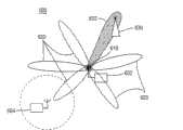
Use in this way adaptive antenna to allow wireless transmission/receive unit to form the directional beam field pattern to realize above-mentioned three any one that optimize in substituting.When creating the directional beam field pattern, adaptive antenna also creates null value.Null value is only for hanging down the direction of antenna gain.Fig. 3 has described this concept.Wireless transmission/receiveunit 302 is shown have for leadbeam field pattern 320 to thebase station 330 aerial array 310.Aerial array 310 also guides nullvalue 321 approximately towards wireless transmission/receiveunit 304, and namely wireless transmission/receive unit is near the source of wireless transmission/receive unit (MS-MS) interference.In this example, nullvalue wave beam 321 has " making no signal " or minimizes by the effect that is transmitted at uplink direction from the caused interference of signal of wireless transmission/receiveunit 304.
In the second preferred embodiment, adaptive antenna array is used to select antenna weight one of to substitute to realize above-mentioned three optimizations.Wireless transmission/receive unit then uses the antenna weight of deriving from selected weight to transmit to the base station.Importantly, notice that institute's transmit weights that derives is selected so that be held for critical positions and the shape of the wave beam of receiver establishment.For example, the transmission antenna weights that derives can be identical with the antenna weight that is selected for the reception signal.
When transmitting wireless transmission/receive unit and be in the mutual interference state with near wireless transmission/receive unit, above-described to use the antenna weight of deriving to transmit be useful especially.For example, when the uplink frequency of the first wireless transmission/receive unit approaches or identical with the down-link frequencies of the second wireless transmission/receive unit and down-link frequencies the first wireless transmission/receive unit approaches or when identical with the uplink frequency of the second wireless transmission/receive unit, wireless transmission/receive unit is described to be in the mutual interference state.In order to illustrate, Fig. 4 shows two wireless transmission/receive units 402 and 404 that are in each other the mutual interference state.TheUL frequency f 1 of WTRU 404 is in close proximity to the DL frequency f 1 ' of WTRU 402.Similarly, the uplink frequency f3 of wireless transmission/receive unit 402 is very near the DL frequency f 3' of wireless transmission/receive unit 404.Therefore, wireless transmission/receive unit 402 and 404 is to be in the mutual interference state each other, and wherein these two wireless transmission/receive units can experience the MS-MS interference when another WTRU is transmitting.
Divide in use in the communication system of duplex (TDD), wireless transmission/receive unit all transmits and receives signal with same frequency.Lacking on time, this wireless transmission/receive unit can experience mutual interference.For example, very approaching or their sequential is not appropriately aimed at genetic system if two time division duplex wireless transmission/reception units are assigned with different time slots or frequency and they frequency separately, and then these wireless transmission/receive units can experience mutual interference.
In the mode identical with mode described in above-mentioned the first preferred embodiment, substitute one of the signal quality of optimizing desired signal with antenna weight to optimize according to above-mentioned three according to the wireless transmission/receive unit of present embodiment.Yet in the present embodiment, wireless transmission/receive unit is derived antenna weight to transmit at uplink direction from selected reception antenna weight.By forming the directional transmissions wave beam with this antenna weight of deriving, the energy of directed contiguous wireless transmission/receive unit will be lowered, and not experience MS-MS with near wireless transmission/receive unit protecting and disturb.
In the 3rd preferred embodiment, switched-beam/switched antenna array (SBSA) is applied to protect in the wireless transmission/receive unit receiver interference that is not subject near wireless transmission/receive unit.Switched-beam/switched antenna array or form a plurality of predetermined beams, the subset of these a plurality of predetermined beams is selected to be used locating at any given time, and perhaps SBSA forms one group of wave beam of larger group from the predetermined beams position.It should be noted that these one of beam pattern that form can be isotropic directivity directional beam field pattern.The example of these predetermined beam patterns is depicted among Fig. 5.Switched-beam/switchedantenna array 510 is shown has its 12predetermined antenna beams 520 and 522.Wave beam 520 is emphasized to be depicted as the wave beam that highest signal quality is provided, may points to base station direction (not shown).
Should be appreciated that Fig. 5 only is intended to be provided as the example of switched-beam/switched antenna array concept.Can have littlely of two predetermined antenna beams according to the switched-beam/switched antenna array system of present embodiment, may comprise one with omnirange orientation response.Quantity by the formed antenna beam of switched-beam/switched antenna array is fewer, and each wave beam will need wider.Beamwidth and number of beams are considered to determine by type of device and size usually.
According to present embodiment, measuring-signal in the predetermined beams of each wireless transmission/receive unit.A wave beam of these wave beams then selected so that: 1) the maximization signal noise that receives signal adds interference ratio (SNIR); Or 2) minimize the energy that is received near wireless transmission/receive unit; Or 3) minimize the signal level that the energy that is received near wireless transmission/receive unit is kept enough expectations simultaneously.The selected beam pattern that handoff functionality then switches to these fixed beam field patterns upwards receives desired signal at downlink side.In some examples, selected wave beam can be the omnirange directional beam.The continuous reduction of the interfering energy of wireless transmission/receive unit is kept by means of frequently switching between the predetermined beam patterns in response to the signal environment of wireless transmission/receive unit near being received from.This concept is depicted in Fig. 6.
Theaerial array 610 of wireless transmission/receiveunit 602 has formed a plurality ofpredetermined beams 620 and 622.Wave beam 622 emphasized to be depicted as initiatively and be guided to base station 630.Therefore, it has reduced the gain towards near wireless transmission/receiveunit 604.
Use in the above described manner switched beam antenna to allow wireless transmission/receive unit from a plurality of predetermined antenna beams, to select.When selecting one of these wave beams, the interference of wireless transmission/receive unit is lowered as shown in Figure 6 near being received from.The attendant advantages of this execution mode is in its simultaneous minimization band and band is outer disturbs.
In the 4th preferred embodiment, switched-beam antenna array is used in the wireless transmission/receive unit to minimize near wireless transmission/receive unit, if the MS-MS that experiences when particularly wireless transmission/receive unit is in the mutual interference state disturbs.As mentioned above, for example when the down-link frequencies of the first wireless transmission/receive unit near the uplink frequency of the second wireless transmission/receive unit and the down-link frequencies of the second wireless transmission/receive unit during near the uplink frequency of the first wireless transmission/receive unit, wireless transmission/receive unit is in mutual interference (seeing Fig. 4).Do not having in the appropriate situation of aiming at, the wireless transmission/receive unit in the tdd communication systems also can experience mutual interference.
In the mode identical with the mode of above-mentioned the 3rd preferred embodiment, wireless transmission/receive unit optionally switches between a plurality of predetermined fixed antenna beams and comes the maximum signal noise plus interference ratio, minimize near the energy of wireless transmission/receive unit being received from, or minimize the signal level that the energy that is received near wireless transmission/receive unit is kept enough expectations simultaneously.Yet in the present embodiment, wireless transmission/receive unit transmits at uplink direction with identical selected antenna beam.Because selected beam minimizes is from the interfering energy of not expecting the source, thus the transmission on the same beam will minimize towards near the transmission of not expecting energy in source.Therefore, by transmitting at selected beam direction, be minimized towards near the interference of wireless transmission/receive unit.
In the 5th preferred embodiment, intelligent antenna array is used to minimize in the wireless transmission/receive unit near wireless transmission/receive unit, and the MS-MS that particularly experiences when wireless transmission/receive unit is in asymmetric disturbance state disturbs.Hereinafter, phrase " smart antenna " is used for describing adaptive antenna array or switched-beam/switched antenna array.For present embodiment, when the down link of the second contiguous wireless transmission/receive unit of the first wireless transmission/receive unit interference spectrum received, wireless transmission/receive unit was in asymmetric disturbance state.Yet the ul transmissions of the second wireless transmission/receive unit does not disturb the down link of the first wireless transmission/receive unit to receive.This concept is depicted in Fig. 7.
Describe such as Fig. 7, can disturb asymmetrically near wireless transmission/receive unit such as the wireless transmission/receive unit of timedivision duplex device 702, and not recognize that this interference occurs.This is unconscious to be to be produced away from the uplink frequency of the wireless transmission/receive unit of being injured on frequency spectrum because of the receive frequency that disturbs wireless transmission/receive unit.Present embodiment proposes by providing extraneous information to disturbing wireless transmission/receive unit to minimize this asymmetric interference.The notified frequency spectrum arrangement that is arranged in its signal environment of asymmetric interference wireless transmission/receive unit (such as the time division duplex wireless transmission/reception unit 702 of Fig. 7).Especially, the uplink frequency of the wireless transmission/receive unit of contiguous its uplink frequency of its notified down-link frequencies.This info alert disturbs relevant this of wireless transmission/receive unit to disturb WTRU may produce to it existence of other wireless transmission/receive unit that disturbs.Disturb wireless transmission/receive unit then to scan the physical location that these uplink frequency are determined these wireless transmission/receive units.For example, disturb wireless transmission/receive unit can determine by the search high energy signals position of these wireless transmission/receive units.Sufficiently high energy level on the uplink direction means wireless transmission/receive unit may be nearby and may be disturbed.Therefore, disturb wireless transmission/receive unit then by adjusting its uplink transmission direction with for example any embodiment described herein, come near the wireless transmission/receive unit of minimise interference.
Alternately, wireless transmission/receive unit can scan all possible frequency, but not notice is disturbed the frequency spectrum arrangement in relevant its signal environment of wireless transmission/receive unit and therefore limited the wireless transmission/receive unit search.Come into question although the assembly of each embodiment is the form with stand-alone assembly, should be appreciated that it can be positioned on the signal integrated circuit (IC), such as the combination of application-specific integrated circuit (ASIC) (ASIC), a plurality of IC, discrete component or discrete component and IC.
Similarly, although characteristic of the present invention and element are described in the preferred embodiment in particular combinations, but each feature or element all can be used alone (in the situation of the further feature that does not have preferred embodiment or element), or have or without the situation of further feature of the present invention and element under be used with various combinations.
Claims (14)
1. one kind is used at the wireless transmission/receive unit of radio communication mitigation of wireless transmit/receive unit to the wireless transmission/receive unit interference, and this wireless transmission/receive unit comprises:
Signal processing unit is configured to measure the signal quality of the signal that receives and calculates antenna weight based on mass measurement;
Aerial array is configured to come the receiving downlink signal based on antenna weight formation direct antenna beam as calculated, and this antenna weight is as calculated calculated the energy minimization receiving at least one contiguous wireless transmission/receive unit place;
Described signal processing unit also is configured to derive transmission antenna weights from described antenna weight as calculated; And
Described aerial array also is configured to form direct antenna beam based on the transmission antenna weights that derives and transmits uplink signal.
2. wireless transmission/receive unit as claimed in claim 1 wherein is exported with identical with the antenna weight that is calculated to be used for the reception signal for the antenna weight that transmits signal.
3. wireless transmission/receive unit as claimed in claim 1, wherein said aerial array also is configured to make reception and the present radio condition of transmit antenna wave beam dynamically adapting of formation.
4. wireless transmission/receive unit as claimed in claim 1 is wherein calculated to add interference ratio for the antenna weight that receives signal for optimizing signal noise ratio or signal noise.
5. wireless transmission/receive unit as claimed in claim 1 is wherein calculated to be used for receiving the antenna weight of signal for minimizing the interference that receives.
6. wireless transmission/receive unit as claimed in claim 1 is wherein calculated to be used for receiving the antenna weight of signal for the minimum interference that receives is kept the fixing signal level that receives simultaneously.
7. wireless transmission/receive unit as claimed in claim 1, wherein said aerial array also are configured to guide null value in the direction that is being formed with beyond the direction of the wave beam that is used for receiving signal.
8. one kind is used in the method for radio communication mitigation of wireless transmit/receive unit to the wireless transmission/receive unit interference, and the method comprises:
The signal quality of the signal that measurement receives;
Calculate antenna weight based on mass measurement, this antenna weight is calculated the energy minimization receiving at least one contiguous wireless transmission/receive unit place;
Come the receiving downlink signal based on antenna weight formation direct antenna beam as calculated;
From this antenna weight as calculated, derive transmission antenna weights; And
Form direct antenna beam based on the transmission antenna weights that derives and transmit uplink signal.
9. method as claimed in claim 8, the antenna weight of wherein deriving equates with antenna weight as calculated.
10. method as claimed in claim 8, the method further comprises makes formed reception and the present radio condition of transmit antenna wave beam dynamically adapting.
11. method as claimed in claim 8, wherein as calculated antenna weight is calculated to optimize signal noise ratio or signal noise adds interference ratio.
12. method as claimed in claim 8, wherein as calculated antenna weight is calculated to minimize the interference that receives.
13. method as claimed in claim 8, wherein as calculated antenna weight is calculated to minimize the interference that receives and is kept simultaneously the fixing signal level that receives.
14. further being included in, method as claimed in claim 8, the method be formed to guide null value on the direction beyond the wave beam that is used for the reception signal.
Applications Claiming Priority (5)
| Application Number | Priority Date | Filing Date | Title |
|---|---|---|---|
| US55796704P | 2004-03-31 | 2004-03-31 | |
| US60/557,967 | 2004-03-31 | ||
| US11/025,252 | 2004-12-29 | ||
| US11/025,252US7630688B2 (en) | 2004-03-31 | 2004-12-29 | Mitigation of wireless transmit/receive unit (WTRU) to WTRU interference using multiple antennas or beams |
| PCT/US2005/008023WO2005104503A2 (en) | 2004-03-31 | 2005-03-10 | Mitigation of wireless transmit/receive unit (wtru) to wtru interference using multiple antennas or beams |
Publications (2)
| Publication Number | Publication Date |
|---|---|
| CN101124803A CN101124803A (en) | 2008-02-13 |
| CN101124803Btrue CN101124803B (en) | 2013-01-23 |
Family
ID=35055056
Family Applications (1)
| Application Number | Title | Priority Date | Filing Date |
|---|---|---|---|
| CN2005800102288AExpired - Fee RelatedCN101124803B (en) | 2004-03-31 | 2005-03-10 | WTRU for mitigation of wireless transmit/receive unit (WTRU) to WTRU interference and method therefor |
Country Status (10)
| Country | Link |
|---|---|
| US (2) | US7630688B2 (en) |
| EP (2) | EP1738564A4 (en) |
| JP (6) | JP2007532059A (en) |
| KR (3) | KR20060131993A (en) |
| CN (1) | CN101124803B (en) |
| AR (2) | AR048352A1 (en) |
| CA (1) | CA2561713C (en) |
| NO (1) | NO340372B1 (en) |
| TW (5) | TWI260933B (en) |
| WO (1) | WO2005104503A2 (en) |
Families Citing this family (41)
| Publication number | Priority date | Publication date | Assignee | Title |
|---|---|---|---|---|
| US7630688B2 (en)* | 2004-03-31 | 2009-12-08 | Interdigital Technology Corporation | Mitigation of wireless transmit/receive unit (WTRU) to WTRU interference using multiple antennas or beams |
| KR100706620B1 (en)* | 2005-05-17 | 2007-04-11 | 한국전자통신연구원 | Beam Selection Method for Initial Synchronization Using Switch Beam |
| US20080056201A1 (en)* | 2006-03-22 | 2008-03-06 | Broadcom Corporation, A California Corporation | Interference parameter reporting from client devices to access point for use in modifying wireless operations |
| EP1843485B1 (en) | 2006-03-30 | 2016-06-08 | Sony Deutschland Gmbh | Multiple-input multiple-output (MIMO) spatial multiplexing system with dynamic antenna beam combination selection capability |
| EP2022180B1 (en)* | 2006-05-29 | 2016-02-03 | Telefonaktiebolaget LM Ericsson (publ) | Channel quality prediction in hsdpa systems |
| JP4972370B2 (en)* | 2006-09-21 | 2012-07-11 | 京セラ株式会社 | Wireless communication apparatus and wireless communication method |
| US20080102768A1 (en)* | 2006-10-25 | 2008-05-01 | Navini Networks, Inc. | Method for Obtaining a Covariance Matrix of a Transmitting Channel in a Wireless Network |
| US7995973B2 (en)* | 2008-12-19 | 2011-08-09 | Telefonaktiebolaget Lm Ericsson (Publ) | Own transmitter interference tolerant transceiver and receiving methods |
| US8855580B2 (en)* | 2008-06-27 | 2014-10-07 | Telefonaktiebolaget L M Ericsson (Publ) | Methods and apparatus for reducing own-transmitter interference in low-IF and zero-IF receivers |
| CN102187725B (en)* | 2008-10-20 | 2014-12-31 | 交互数字专利控股公司 | Carrier aggregation |
| KR101303709B1 (en)* | 2008-10-31 | 2013-09-03 | 인터디지탈 패튼 홀딩스, 인크 | Method and apparatus for utilizing multiple carriers in high speed packet access communications |
| US8385281B2 (en) | 2009-01-30 | 2013-02-26 | Interdigital Patent Holdings, Inc. | Method and apparatus for component carrier aggregation in wireless communications |
| US8023915B2 (en)* | 2009-03-30 | 2011-09-20 | Mitsubishi Electric Research Laboratories, Inc. | Beamforming in wireless vehicular networks |
| PH12012500961A1 (en)* | 2009-11-30 | 2021-06-23 | Ericsson Telefon Ab L M | Interference mitigation in downlink signal communication to a mobile terminal |
| EP2517376B1 (en)* | 2009-12-21 | 2016-11-02 | Telefonaktiebolaget LM Ericsson (publ) | Method for suppressing opposite direction interference |
| US20140160968A1 (en)* | 2011-07-04 | 2014-06-12 | Telefonaktiebolaget L M Ericsson (Publ) | Enhanced Use of Frequency Spectrum in a Wireless Communication Network |
| KR101800221B1 (en) | 2011-08-11 | 2017-11-22 | 삼성전자주식회사 | Method and apparatus for beam tracking in wireless communication system |
| KR101839808B1 (en)* | 2011-08-24 | 2018-04-26 | 삼성전자주식회사 | Mobile Terminal and Communication Method, Base Station Control Apparatus and Method, and Multi-Point Transmission System and Method using the Same |
| EP2769485A1 (en)* | 2011-10-19 | 2014-08-27 | Marvell World Trade Ltd. | Systems and methods for suppressing interference in a signal received by a device having two or more antennas |
| US9054765B2 (en) | 2011-10-20 | 2015-06-09 | Marvell World Trade Ltd. | Systems and methods for suppressing interference in a wireless communication system |
| WO2014003499A1 (en)* | 2012-06-29 | 2014-01-03 | Samsung Electronics Co., Ltd. | Method and apparatus for beamforming |
| CN104335508B (en)* | 2012-07-02 | 2017-09-12 | 英特尔公司 | Launch simultaneously and receive |
| JP2014114006A (en)* | 2012-11-16 | 2014-06-26 | Tokai Rika Co Ltd | Tire position determination device |
| CN103856306B (en)* | 2012-12-05 | 2017-10-17 | 华为技术有限公司 | Handle the method and device of interference |
| US9071474B1 (en) | 2013-07-25 | 2015-06-30 | Marvell International Ltd. | Systems and methods for suppressing interference in a wireless communication system |
| US9806827B2 (en)* | 2013-09-13 | 2017-10-31 | Samsung Electronics Co., Ltd. | Computing system with interference cancellation mechanism and method of operation thereof |
| EP2930994B1 (en)* | 2014-04-07 | 2016-05-18 | Alcatel Lucent | Mitigating UL-to-DL interference |
| US9960828B2 (en)* | 2014-05-08 | 2018-05-01 | Telefonaktiebolaget Lm Ericsson (Publ) | Beam forming using an antenna arrangement |
| US9578644B2 (en) | 2014-09-26 | 2017-02-21 | Mediatek Inc. | Beam misalignment detection for wireless communication system with beamforming |
| CN107251618B (en)* | 2015-01-16 | 2021-05-14 | 梁平 | Beamforming in a multi-user multiple-input multiple-output wireless communication system with repeaters |
| US9806781B2 (en)* | 2015-04-29 | 2017-10-31 | Samsung Electronics Co., Ltd. | Codebook design and structure for advanced wireless communication systems |
| JP2017059933A (en)* | 2015-09-15 | 2017-03-23 | 日本電気株式会社 | Communication system, base station, and antenna control method |
| US20170303328A1 (en)* | 2016-04-15 | 2017-10-19 | Intel IP Corporation | Antenna weight vector group identification for wireless communication |
| US10833832B2 (en) | 2016-06-22 | 2020-11-10 | Intel Corporation | Communication device and a method for full duplex scheduling |
| US10333599B2 (en)* | 2016-09-13 | 2019-06-25 | Corning Optical Communications LLC | Antenna array beamforming in a remote unit(s) in a wireless distribution system (WDS) |
| KR102470863B1 (en) | 2018-03-09 | 2022-11-28 | 삼성전자주식회사 | Method and appatus of interference measurement |
| CN112205043A (en)* | 2018-05-30 | 2021-01-08 | 株式会社Ntt都科摩 | communication device |
| KR102018254B1 (en)* | 2018-09-10 | 2019-09-04 | 에스케이텔레콤 주식회사 | Signal transmitting apparatus and signal transmitting method |
| CN114008857B (en)* | 2020-03-30 | 2023-10-10 | 华为技术有限公司 | Antenna system, control method, processor and image pickup system |
| WO2022137493A1 (en)* | 2020-12-25 | 2022-06-30 | 日本電信電話株式会社 | Signal processing device, wireless communication system, and signal processing method |
| WO2024077211A1 (en)* | 2022-10-07 | 2024-04-11 | Interdigital Patent Holdings, Inc. | Methods, procedures, and devices to improve beam resilience in multi-antenna systems with hybrid beamforming |
Citations (6)
| Publication number | Priority date | Publication date | Assignee | Title |
|---|---|---|---|---|
| US5574983A (en)* | 1993-09-29 | 1996-11-12 | Ntt Mobile Communications Network Inc. | Base station device and mobile station device in mobile communication system utilizing the site diversity effect in soft handover state |
| US5631898A (en)* | 1994-01-11 | 1997-05-20 | Ericsson Inc. | Cellular/satellite communications system with improved frequency re-use |
| CN1235389A (en)* | 1998-04-03 | 1999-11-17 | 朗迅科技公司 | Adaptive antenna |
| CN1336046A (en)* | 1999-11-10 | 2002-02-13 | 三菱电机株式会社 | Adaptive arry communication system and receiver |
| WO2003075396A2 (en)* | 2002-03-01 | 2003-09-12 | Cognio Inc | System and method for antenna diversity using joint maximal ratio combining |
| WO2004023665A2 (en)* | 2002-09-09 | 2004-03-18 | Interdigital Technology Corporation | Vertical dynamic beam-forming |
Family Cites Families (42)
| Publication number | Priority date | Publication date | Assignee | Title |
|---|---|---|---|---|
| JP3497672B2 (en)* | 1996-09-18 | 2004-02-16 | 株式会社東芝 | Adaptive antenna and multi-carrier wireless communication system |
| JP3464606B2 (en)* | 1998-03-31 | 2003-11-10 | 松下電器産業株式会社 | Wireless communication device and wireless communication method |
| US6188915B1 (en)* | 1998-05-19 | 2001-02-13 | Harris Corporation | Bootstrapped, piecewise-asymptotic directivity pattern control mechanism setting weighting coefficients of phased array antenna |
| KR100272565B1 (en)* | 1998-06-16 | 2000-11-15 | 서평원 | Method for allocating Optimal Orthogonal Code of Reverse Link |
| US6229486B1 (en)* | 1998-09-10 | 2001-05-08 | David James Krile | Subscriber based smart antenna |
| US6314305B1 (en)* | 1998-12-10 | 2001-11-06 | Lucent Technologies Inc. | Transmitter/receiver for combined adaptive array processing and fixed beam switching |
| GB2349045A (en) | 1999-04-16 | 2000-10-18 | Fujitsu Ltd | Base station transmission beam pattern forming; interference reduction |
| EP1172956B1 (en)* | 1999-04-22 | 2008-08-13 | Nippon Telegraph and Telephone Corporation | OFDM packet communication receiver |
| US6661832B1 (en)* | 1999-05-11 | 2003-12-09 | Qualcomm Incorporated | System and method for providing an accurate estimation of received signal interference for use in wireless communications systems |
| JP3387459B2 (en)* | 1999-09-30 | 2003-03-17 | 日本電気株式会社 | Radio monitoring system and radio monitoring method |
| US7046678B2 (en)* | 2000-02-18 | 2006-05-16 | At & T Corp. | Channel efficiency based packet scheduling for interactive data in cellular networks |
| JP2001237756A (en)* | 2000-02-25 | 2001-08-31 | Matsushita Electric Ind Co Ltd | Array antenna wireless communication device and array antenna wireless communication method |
| US6940845B2 (en)* | 2000-03-23 | 2005-09-06 | At & T, Corp. | Asymmetric measurement-based dynamic packet assignment system and method for wireless data services |
| WO2002007342A1 (en)* | 2000-07-14 | 2002-01-24 | Sanyo Electric Co., Ltd. | Mobile communication terminal, communication method, and program |
| EP1309104B1 (en)* | 2000-07-14 | 2011-06-08 | Sanyo Electric Co., Ltd. | Calibration device, adaptive array device, calibration method, program recording medium and program |
| US6400315B1 (en)* | 2000-07-20 | 2002-06-04 | The Boeing Company | Control system for electronically scanned phased array antennas with a mechanically steered axis |
| DE60008930T2 (en)* | 2000-12-04 | 2005-01-27 | Mitsubishi Denki K.K. | SYNTHESIS RECEIVING METHOD AND SYNTHESIS RECEIVER |
| JP4282227B2 (en)* | 2000-12-28 | 2009-06-17 | 日本電気株式会社 | Noise removal method and apparatus |
| US20020146044A1 (en)* | 2001-04-09 | 2002-10-10 | Riaz Esmailzadeh | Hybrid single/multiuser interference reduction detector |
| JP2002325062A (en) | 2001-04-25 | 2002-11-08 | Mitsubishi Electric Corp | Mobile communication system and mobile communication terminal device |
| US6621454B1 (en)* | 2001-05-10 | 2003-09-16 | Vectrad Networks Corporation | Adaptive beam pattern antennas system and method for interference mitigation in point to multipoint RF data transmissions |
| JP2003018074A (en)* | 2001-06-29 | 2003-01-17 | Toshiba Corp | Radio base station and beam control method |
| EP1667341B1 (en)* | 2001-07-11 | 2011-03-02 | Sony Deutschland GmbH | Method for calculating a weighting vector for an antenna array |
| US7031702B2 (en)* | 2001-09-14 | 2006-04-18 | Atc Technologies, Llc | Additional systems and methods for monitoring terrestrially reused satellite frequencies to reduce potential interference |
| KR100566241B1 (en)* | 2001-11-19 | 2006-03-29 | 삼성전자주식회사 | Apparatus and method for combining soft symbols in mobile communication system |
| CA2415170C (en)* | 2001-12-28 | 2008-07-15 | Ntt Docomo, Inc. | Receiver, transmitter, communication system, and method of communication |
| JP3866118B2 (en) | 2002-02-27 | 2007-01-10 | 日本電信電話株式会社 | Space division multiple access apparatus, adaptive array antenna base station, terminal and control method thereof |
| JP3600218B2 (en)* | 2002-03-20 | 2004-12-15 | 三洋電機株式会社 | Wireless terminal device, transmission directivity control method, and transmission directivity control program |
| US7424268B2 (en)* | 2002-04-22 | 2008-09-09 | Cisco Technology, Inc. | System and method for management of a shared frequency band |
| CN100481988C (en) | 2002-05-13 | 2009-04-22 | 美商内数位科技公司 | Allocating resources to users in a slotted CDMA system using beams |
| KR100689399B1 (en)* | 2002-05-17 | 2007-03-08 | 삼성전자주식회사 | Apparatus and method for forward transmission beam forming of smart antenna in mobile communication system |
| EP1369954A3 (en)* | 2002-06-05 | 2004-10-20 | Fujitsu Limited | Adaptive antenna unit for mobile terminal |
| US7339981B2 (en)* | 2002-07-09 | 2008-03-04 | Arraycomm, Llc. | Shifted training sequences in a communications system |
| GB2393077A (en) | 2002-09-14 | 2004-03-17 | Roke Manor Research | Aligning a directional antenna towards an access point using location information |
| US7412212B2 (en)* | 2002-10-07 | 2008-08-12 | Nokia Corporation | Communication system |
| JP2004180038A (en)* | 2002-11-28 | 2004-06-24 | Nec Infrontia Corp | Wireless lan access point, wireless lan system, and method of preventing interference between wireless lan access points |
| JP3930456B2 (en) | 2003-05-29 | 2007-06-13 | 日本無線株式会社 | Array antenna communication device |
| US6879829B2 (en)* | 2003-05-16 | 2005-04-12 | Mobile Satellite Ventures, Lp | Systems and methods for handover between space based and terrestrial radioterminal communications, and for monitoring terrestrially reused satellite frequencies at a radioterminal to reduce potential interference |
| US7295831B2 (en)* | 2003-08-12 | 2007-11-13 | 3E Technologies International, Inc. | Method and system for wireless intrusion detection prevention and security management |
| US7457590B2 (en)* | 2003-12-23 | 2008-11-25 | Motorola, Inc. | Method, apparatus and system for use in the transmission of wireless communications using multiple antennas |
| US7782987B2 (en)* | 2004-03-12 | 2010-08-24 | Telefonaktiebolaget Lm Ericsson (Publ) | Method and apparatus for received signal quality estimation |
| US7630688B2 (en)* | 2004-03-31 | 2009-12-08 | Interdigital Technology Corporation | Mitigation of wireless transmit/receive unit (WTRU) to WTRU interference using multiple antennas or beams |
- 2004
- 2004-12-29USUS11/025,252patent/US7630688B2/ennot_activeExpired - Fee Related
- 2005
- 2005-03-10EPEP05725282Apatent/EP1738564A4/ennot_activeWithdrawn
- 2005-03-10TWTW094107353Apatent/TWI260933B/ennot_activeIP Right Cessation
- 2005-03-10KRKR1020067021409Apatent/KR20060131993A/ennot_activeCeased
- 2005-03-10WOPCT/US2005/008023patent/WO2005104503A2/enactiveSearch and Examination
- 2005-03-10TWTW097108405Apatent/TWI377800B/ennot_activeIP Right Cessation
- 2005-03-10TWTW101118078Apatent/TWI454081B/ennot_activeIP Right Cessation
- 2005-03-10CACA2561713Apatent/CA2561713C/ennot_activeExpired - Fee Related
- 2005-03-10TWTW103115738Apatent/TWI533638B/ennot_activeIP Right Cessation
- 2005-03-10EPEP11187124Apatent/EP2413515A3/ennot_activeWithdrawn
- 2005-03-10KRKR1020067022591Apatent/KR20060130770A/ennot_activeCeased
- 2005-03-10KRKR1020107008981Apatent/KR20100054876A/ennot_activeCeased
- 2005-03-10JPJP2007506203Apatent/JP2007532059A/enactivePending
- 2005-03-10CNCN2005800102288Apatent/CN101124803B/ennot_activeExpired - Fee Related
- 2005-03-10TWTW094131743Apatent/TWI350076B/ennot_activeIP Right Cessation
- 2005-03-30ARARP050101246Apatent/AR048352A1/enactiveIP Right Grant
- 2006
- 2006-10-25NONO20064846Apatent/NO340372B1/ennot_activeIP Right Cessation
- 2009
- 2009-01-09ARARP090100059Apatent/AR070131A2/enunknown
- 2009-02-26JPJP2009044792Apatent/JP2009135963A/enactivePending
- 2009-12-07USUS12/632,420patent/US7835700B2/ennot_activeExpired - Fee Related
- 2012
- 2012-07-30JPJP2012168710Apatent/JP2012217212A/enactivePending
- 2013
- 2013-06-03JPJP2013117217Apatent/JP6026958B2/ennot_activeExpired - Fee Related
- 2014
- 2014-12-24JPJP2014261288Apatent/JP6027085B2/ennot_activeExpired - Fee Related
- 2016
- 2016-02-29JPJP2016037907Apatent/JP6368729B2/ennot_activeExpired - Fee Related
Patent Citations (6)
| Publication number | Priority date | Publication date | Assignee | Title |
|---|---|---|---|---|
| US5574983A (en)* | 1993-09-29 | 1996-11-12 | Ntt Mobile Communications Network Inc. | Base station device and mobile station device in mobile communication system utilizing the site diversity effect in soft handover state |
| US5631898A (en)* | 1994-01-11 | 1997-05-20 | Ericsson Inc. | Cellular/satellite communications system with improved frequency re-use |
| CN1235389A (en)* | 1998-04-03 | 1999-11-17 | 朗迅科技公司 | Adaptive antenna |
| CN1336046A (en)* | 1999-11-10 | 2002-02-13 | 三菱电机株式会社 | Adaptive arry communication system and receiver |
| WO2003075396A2 (en)* | 2002-03-01 | 2003-09-12 | Cognio Inc | System and method for antenna diversity using joint maximal ratio combining |
| WO2004023665A2 (en)* | 2002-09-09 | 2004-03-18 | Interdigital Technology Corporation | Vertical dynamic beam-forming |
Also Published As
Similar Documents
| Publication | Publication Date | Title |
|---|---|---|
| CN101124803B (en) | WTRU for mitigation of wireless transmit/receive unit (WTRU) to WTRU interference and method therefor | |
| US10951272B2 (en) | Systems, methods and devices for beam selection in a wireless communication system | |
| KR100817620B1 (en) | Method and apparatus for adapting antenna array using received predetermined signal | |
| KR101839808B1 (en) | Mobile Terminal and Communication Method, Base Station Control Apparatus and Method, and Multi-Point Transmission System and Method using the Same | |
| KR101910852B1 (en) | Method and apparatus for trnasmitting and receiving random access information in a wireless communication system | |
| US9252864B2 (en) | Method and apparatus for fast beam-link construction in mobile communication system | |
| KR101791270B1 (en) | Method and apparatus for jointly transmitting/receiving a signal in a mobile communication system | |
| US8374607B2 (en) | Data processing in intra-site handover | |
| US20170181193A1 (en) | Method and apparatus for receiving uplink signal | |
| JP2009159585A (en) | Interference suppression method between different types of wireless communication systems, base station cooperation interference suppression system, and mobile communication system | |
| US20230209510A1 (en) | Radio communication method, radio communication system, radio base station, and repeater | |
| JP3832083B2 (en) | Base station antenna device | |
| US10128926B2 (en) | Method and device for transmitting signal | |
| US20060084387A1 (en) | Method and system for suppressing unwanted responses in wireless communication systems | |
| HK1109272B (en) | Wtru and method for mitigating wtru to wtru interference in wireless communications | |
| MXPA06011246A (en) | Mitigation of wireless transmit/receive unit (wtru) to wtru interference using multiple antennas or beams |
Legal Events
| Date | Code | Title | Description |
|---|---|---|---|
| C06 | Publication | ||
| PB01 | Publication | ||
| C10 | Entry into substantive examination | ||
| SE01 | Entry into force of request for substantive examination | ||
| REG | Reference to a national code | Ref country code:HK Ref legal event code:DE Ref document number:1109272 Country of ref document:HK | |
| C14 | Grant of patent or utility model | ||
| GR01 | Patent grant | ||
| REG | Reference to a national code | Ref country code:HK Ref legal event code:GR Ref document number:1109272 Country of ref document:HK | |
| CF01 | Termination of patent right due to non-payment of annual fee | Granted publication date:20130123 Termination date:20200310 | |
| CF01 | Termination of patent right due to non-payment of annual fee |