CN101123863A - Wind scooper - Google Patents
Wind scooperDownload PDFInfo
- Publication number
- CN101123863A CN101123863ACNA2006101154286ACN200610115428ACN101123863ACN 101123863 ACN101123863 ACN 101123863ACN A2006101154286 ACNA2006101154286 ACN A2006101154286ACN 200610115428 ACN200610115428 ACN 200610115428ACN 101123863 ACN101123863 ACN 101123863A
- Authority
- CN
- China
- Prior art keywords
- wind scooper
- electro
- heat
- air
- heat equipment
- Prior art date
- Legal status (The legal status is an assumption and is not a legal conclusion. Google has not performed a legal analysis and makes no representation as to the accuracy of the status listed.)
- Pending
Links
- 230000005855radiationEffects0.000claimsabstractdescription6
- 238000009423ventilationMethods0.000claimsdescription13
- 239000002390adhesive tapeSubstances0.000claims1
- 238000010438heat treatmentMethods0.000abstractdescription42
- 238000001816coolingMethods0.000description25
- 230000017525heat dissipationEffects0.000description19
- 230000000694effectsEffects0.000description9
- 238000010586diagramMethods0.000description2
- 238000005516engineering processMethods0.000description2
- 238000013021overheatingMethods0.000description2
- 238000009825accumulationMethods0.000description1
- 238000007664blowingMethods0.000description1
- 239000012141concentrateSubstances0.000description1
- 230000009977dual effectEffects0.000description1
- 230000006870functionEffects0.000description1
- 230000020169heat generationEffects0.000description1
- 230000007774longtermEffects0.000description1
- 238000000034methodMethods0.000description1
Images

Landscapes
- Cooling Or The Like Of Electrical Apparatus (AREA)
Abstract
Description
Translated fromChinese技术领域technical field
本发明涉及一种导风罩,更详言之,涉及一种用以将散热风扇的气流导引至发热装置的导风罩。The present invention relates to an air guide cover, and more specifically, relates to an air guide cover for guiding the airflow of a cooling fan to a heating device.
背景技术Background technique
随着电子科技不断的进步与发展,电子设备已成为人类生活中不可或缺的一部份,然而电子设备中又以电脑的应用最为广泛,且电脑中有许多主要电子元件,而众多电子元件中又以主机板设置的电子元件是最多的,随着电子设备的功能不断地增加及提升,其所装设的电子元件亦越来越多,然而,当该电子设备运行时,该电子元件及元件亦会产生热能,故,如何使该电子元件及元件在运行时所产生的热能能够充分散热,而使该电子元件及元件不会因产生过热而造成该电子设备运行不稳,是目前电子设备所面临的棘手问题。With the continuous progress and development of electronic technology, electronic equipment has become an indispensable part of human life. However, among electronic equipment, computers are the most widely used, and there are many main electronic components in computers, and many electronic components Among them, the main board has the most electronic components. With the continuous increase and improvement of the functions of electronic equipment, more and more electronic components are installed. However, when the electronic equipment is running, the electronic components And components will also generate heat energy, so how to make the heat energy generated by the electronic components and components during operation can be fully dissipated, so that the electronic components and components will not cause the electronic equipment to run unstable due to overheating. Difficult problems facing electronic devices.
应用于电子设备的散热装置绝大部份是装设多个风扇来对电子设备内部的电子元件及元件提供热对流的散热效果,而电子设备的内部空间有限,亦无法装设过多的风扇进行热对流,且电子设备内部各元件及元件配置相当密集,该对流空气难以通过所有电子元件及元件,或是通过各元件及元件的流量不一,导致部份元件及元件的散热效果不彰,特别是中央处理器及存储器等高发热元件。当电子设备全时工作下若未能提供足够且连续的对流冷空气对高热元件进行热对流,易因上述高发热元件过热而造成内部零元件烧毁或者当机的情形。Most of the cooling devices used in electronic equipment are equipped with multiple fans to provide heat convection cooling effect for the electronic components and components inside the electronic equipment, and the internal space of electronic equipment is limited, and it is impossible to install too many fans Heat convection is carried out, and the components and components inside the electronic equipment are arranged quite densely. It is difficult for the convective air to pass through all the electronic components and components, or the flow rate of each component and components is different, resulting in poor heat dissipation effect of some components and components. , especially high heating components such as central processing unit and memory. When electronic equipment is working full-time, if sufficient and continuous convective cold air is not provided for heat convection of high-heat components, it is easy to cause internal components to burn out or crash due to overheating of the above-mentioned high-heat components.
请参阅图1,服务器1中具有接置于中央处理单元(图未示)的散热块体10及存储器单元11,而为了散逸中央处理单元及存储器单元11因运行而产生的热能,该服务器1中并具有散热风扇12其所产生的气流直接吹往该散热块体10,而剩余的气流则越过该散热块体10流动至该存储器单元11。Referring to Fig. 1, there is a cooling block 10 and a memory unit 11 connected to the central processing unit (not shown) in the server 1, and in order to dissipate the heat energy generated by the central processing unit and the memory unit 11 due to operation, the server 1 There is a heat dissipation fan 12 in the middle, and the airflow generated by it is directly blown to the heat dissipation block 10 , while the rest of the airflow passes over the heat dissipation block 10 to the memory unit 11 .
中央处理单元及存储器单元11在服务器1中配置的考量主要在于中央处理器为主要发热装置而该存储器单元11则为次发热装置,因此必须将主要发热装置设于最接近散热风扇12之处以直接接收风力最强且最低温的散热气流。The consideration of central processing unit and memory unit 11 disposing in server 1 mainly is that central processing unit is main heating device and this memory unit 11 is then secondary heat generating device, therefore must be located at the place of main heat generating device closest to cooling fan 12 to directly Receives the strongest and coldest cooling airflow.
但是,存储器单元11的发热量虽不及在该中央处理单元,然而长期运行下所产生的热能亦十分可观,当服务器1具有宽阔的内部空间时,存储器单元11所产生的热能可通过自然的热对流而降温,然而当服务器1为厚度单位为1U的服务器时,存储器单元11将会有热对流不及的现象,而散热气流亦因服务器1内部空间的狭小而难以流动至存储器单元11,因而容易使存储器单元11过热。However, although the heat generation of the memory unit 11 is not as high as that of the central processing unit, the heat energy generated under long-term operation is also very considerable. However, when the server 1 is a server whose thickness unit is 1U, the memory unit 11 will have insufficient heat convection, and the heat dissipation airflow is also difficult to flow to the memory unit 11 due to the small internal space of the server 1, so it is easy The memory cell 11 is overheated.
后来有人提出一种罩覆该散热块体10的导风罩以将散热风扇12的气流导引至该存储器单元11,然而当服务器1为1U服务器时,中央处理单元上的散热块体10已接近于该服务器1的顶面而阻挡了大部份的气流,而所能流动至存储器单元11的气流均为先行与该散热块体10上的散热鳍片热对流过后的高温气流,因此该导风罩仅能略为加强并集中散热风扇的气流而对于提升存储器单元11的散热效果并无明显功效。Later, someone proposed a wind guide covering the cooling block 10 to guide the air flow of the cooling fan 12 to the memory unit 11. However, when the server 1 is a 1U server, the cooling block 10 on the central processing unit has been Close to the top surface of the server 1 blocks most of the airflow, and the airflow that can flow to the memory unit 11 is the high-temperature airflow that first convects with the heat dissipation fins on the heat dissipation block 10, so the The air guide cover can only slightly strengthen and concentrate the airflow of the cooling fan but has no obvious effect on improving the cooling effect of the memory unit 11 .
另外,服务器1中的存储器单元11为多条并列,而导致位于中央区域的存储器容易产生聚热的现象,即使散热气流可流动至该存储器单元11,亦不易将存储器单元11中央区域的热能散逸。In addition, a plurality of memory units 11 in the server 1 are arranged side by side, so that the memory located in the central area is prone to heat accumulation. Even if the cooling air flow can flow to the memory unit 11, it is not easy to dissipate the heat energy in the central area of the memory unit 11. .
因此,如何研发一种新的技术以改善上述缺点,实为业界亟待克服的课题。Therefore, how to develop a new technology to improve the above shortcomings is an urgent task to be overcome in the industry.
发明内容Contents of the invention
鉴于以上所述现有技术的缺点,本发明目的之一在于提供一种导风罩,从而使受主发热装置阻挡的次发热装置可具有良好的散热效果。In view of the above-mentioned shortcomings of the prior art, one object of the present invention is to provide an air guide cover, so that the secondary heat-generating device blocked by the main heat-generating device can have a good heat dissipation effect.
本发明的次一目的在于提供一种导风罩,从而散逸存储器单元中央区域的热能。A second object of the present invention is to provide a wind deflector so as to dissipate heat energy in the central area of the memory unit.
为达上述及其它目的,本发明提供一种导风罩,应用于一内部至少具有呈纵向依序设置的散热风扇、第一发热装置以及第二发热装置的电子设备,其中该电子设备具有一上盖,该导风罩包括:一盖板,至少盖覆于该第一发热装置,并在对应该第一发热装置的位置设有一导风开口;以及多个侧板,接置于该盖板的相对两侧,该些侧板与该盖板构成一第一通道,该导风开口与该上盖构成一第二通道,该散热风扇的气流经由该第一通道而散逸该第一发热装置的热能,该散热风扇的气流并可经由该第二通道导引至该第二发热装置,从而散逸该第二发热装置的热能。In order to achieve the above and other purposes, the present invention provides an air guide cover, which is applied to an electronic device that has at least a heat dissipation fan, a first heating device, and a second heating device arranged vertically in sequence, wherein the electronic device has a The upper cover, the wind guide cover includes: a cover plate, at least covering the first heat generating device, and having an air guide opening at a position corresponding to the first heat generating device; and a plurality of side plates connected to the cover On the opposite sides of the plate, the side plates and the cover plate form a first channel, the air guide opening and the upper cover form a second channel, and the air flow of the heat dissipation fan dissipates the first heat through the first channel The heat energy of the device and the airflow of the cooling fan can be guided to the second heat generating device through the second channel, thereby dissipating the heat energy of the second heat generating device.
该电子设备可为厚度单位为1U的服务器。该第一发热装置可为接置于中央处理器(CPU)上的散热块体,而该第二发热装置则可为存储器单元(RAM)。该导风罩在相对两端分别构成一入风口及一第一出风口,该入风口及该第一出风口分别与该第一通道连通,从而使该导风罩以该入风口将气流导入该第一通道,并以该第一出风口将气流导出。The electronic device may be a server whose thickness unit is 1U. The first heat generating device can be a cooling block connected to a central processing unit (CPU), and the second heat generating device can be a memory unit (RAM). The air guide cover forms an air inlet and a first air outlet at opposite ends respectively, and the air inlet and the first air outlet are respectively communicated with the first passage, so that the air guide cover uses the air inlet to guide the airflow The first channel is used to guide the airflow out through the first air outlet.
相比于现有技术中存储器单元受到CPU的散热块体阻挡散热气流而有散热效能不佳的缺点,本发明的导风罩因具有导风开口而使得散热气流得以由该第二通道导引至该第二发热单元,使该第二发热装置因接收到足量且低温的气流而可迅速地散逸热量。Compared with the memory unit in the prior art, which is blocked by the heat dissipation block of the CPU and has the disadvantage of poor heat dissipation performance, the air guide cover of the present invention has the air guide opening so that the heat dissipation airflow can be guided by the second channel To the second heating unit, the second heating device can quickly dissipate heat due to receiving sufficient and low-temperature airflow.
该导风罩是罩覆该第一发热装置及部份的第二发热装置,而该导风开口至少涵盖该第一发热装置,较佳地该导风开口延伸至该第二发热装置上方。该盖板还可以设有一连通于该第一出风口的通风缺口,该通风缺口至少涵盖该第二发热装置的中央区域以减少该中央区域的风阻,从而使集中于该中央区域的热能可迅速地散逸而出,一般而言,该第一出风口接近电子设备后方的通风开口,因此亦可通过外部的冷空气流入该通风缺口而进一步地散逸该第二发热装置中央区域的热能。相比于现有技术存储器单元的中央区域容易积热的现象,本发明的导风罩因具有通风缺口而可快速地将第二发热装置(存储器单元)中央区域的热能散逸而出。The wind guide cover covers the first heat generating device and part of the second heat generating device, and the air guide opening at least covers the first heat generating device, preferably the air guide opening extends above the second heat generating device. The cover plate can also be provided with a ventilation gap connected to the first air outlet, the ventilation gap at least covers the central area of the second heating device to reduce the wind resistance of the central area, so that the heat energy concentrated in the central area can be quickly Generally speaking, the first air outlet is close to the ventilation opening at the rear of the electronic equipment, so the external cold air can also flow into the ventilation gap to further dissipate the heat energy in the central area of the second heat generating device. Compared with the phenomenon that the central area of the memory unit in the prior art is easy to accumulate heat, the air guide cover of the present invention can quickly dissipate the heat energy in the central area of the second heat generating device (memory unit) due to the ventilation gap.
另外,该导风罩复具有一相对于该入风口且导通该第一通道的第二出风口,且该电子设备在该第一发热装置(散热块体)旁还可以设有一第三发热装置其亦可为接置于一中央处理单元(CPU)上的散热块体。In addition, the air guide cover has a second air outlet opposite to the air inlet and leading to the first channel, and the electronic equipment can also be provided with a third heat generating device (radiating block) beside the first heat generating device (radiation block). The device can also be a cooling block connected to a central processing unit (CPU).
由上可知,本发明的导风罩可改善现有缺点,因此具有高度产业利用价值。From the above, it can be seen that the air guide cover of the present invention can improve the existing disadvantages, so it has high industrial application value.
附图说明Description of drawings
图1是显示一服务器中关于散热风扇以及各主要发热装置的示意图;FIG. 1 is a schematic diagram showing a cooling fan and main heating devices in a server;
图2A至图2C是显示本发明的导风罩的一较佳具体实施例;以及2A to 2C show a preferred embodiment of the wind deflector of the present invention; and
图3是显示本发明的导风罩的另一较佳具体实施例。FIG. 3 shows another preferred embodiment of the wind deflector of the present invention.
主要元件符号说明Description of main component symbols
1服务器1 server
10散热块体10 cooling blocks
11存储器单元11 memory cells
12散热风扇12 cooling fan
2电子设备2 electronic equipment
20散热风扇20 cooling fan
21第一发热装置21 The first heating device
22第二发热装置22 second heating device
23第三发热装置23 The third heating device
24上盖24 cover
3导风罩3 wind hood
30盖板30 cover
301通风开口301 ventilation opening
302气密胶条302 airtight strip
303导流板303 deflector
304遮挡板304 shielding plate
31入风口31 air inlet
32第一出风口32 The first air outlet
33侧板33 side panels
34第一通道34 first channel
35第二出风口35 second air outlet
36第二通道36 second channel
37通风缺口37 ventilation gaps
A 气流A Airflow
A1气流A1 Airflow
A2气流A2 Airflow
实施方式Implementation
以下通过特定的具体实例说明本发明的实施方式,熟悉此技艺的人士可由本说明书所揭示的内容轻易地了解本发明的其他优点与功效。Embodiments of the present invention are described below through specific examples, and those skilled in the art can easily understand other advantages and effects of the present invention from the content disclosed in this specification.
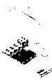
以下图2A至图2C是说明本发明的导风罩的一较佳具体实施例。FIG. 2A to FIG. 2C below illustrate a preferred embodiment of the wind deflector of the present invention.
请参阅图2A,本发明所提供的导风罩3应用于至少具有呈纵向依序设置的散热风扇20、第一发热装置21及第二发热装置22的电子设备2,其中,该散热风扇20用以散逸该第一、二发热装置所产生的热能,本发明的导风罩3包括:盖板30,至少盖覆于该第一发热装置21,并在对应该第一发热装置21的位置设有一导风开口301;以及多个侧板33,接置于该盖板30的相对两侧,该些侧板33与该盖板30并构成一第一通道34。该导风罩3在相对两端分别具有一入风口31及一第一出风口32,该入风口31及该第一出风口32分别与该第一通道34连通,从而使该导风罩3以该入风口31将气流导入该第一通道35,并由该第一出风口32将气流导出,以散逸该第一发热装置21的热能。此外,该盖板30在上方靠近该导风开口301的边缘设有气密胶条302。Please refer to FIG. 2A , the
该电子设备2可为厚度单位为1U的服务器,该第一发热装置21可为接置在中央处理单元(CPU)上的散热块体,而该第二发热装置22则可为多并列的存储器存储器单元(RAM)。然而该电子设备2、第一发热装置21、以及第二发热装置22并非以上所述者为限,而可加以变化,而所述变化为熟悉本发明领域者所能思及并加以应用,例如该电子设备2可为刀锋服务器的刀锋托架,该第一发热装置21可为硬盘模块,而该第二发热装置22可为工作晶片等。The
此外,该电子设备2在该第一发热装置21(散热块体)旁还可以设有一第三发热装置23其亦可为接置于一中央处理单元(CPU,图未示)上的散热块体,即该电子设备2可为一具有双中央处理单元的1U服务器,因此该导风罩3还可以设有另一相对于该入风口31且导通该第一通道34的第二出风口35,并使该第三发热装置23容纳于该入风口31及该第二出风口35之间,从而使散热风扇20的气流亦可用于散逸该第三发热装置23运转时所产生的热能。In addition, the
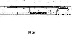
请配合参阅图2B,该电子设备2具有一上盖24,该第一发热装置21通过该导风开口301与该上盖24构成一第二通道36,使该散热风扇20运转所形成的气流A由该入风口31进入第一通道34后分为吹拂于该第一发热装置21的气流A1及经由该第二通道36而导引至该第二发热装置22的气流A2。Please refer to FIG. 2B, the
相比于现有技术中存储器存储器单元受到CPU的散热块体阻挡散热气流而有散热效能不佳的缺点,本发明的导风罩3因具有导风开口301而使得气流A2得以由该第二通道36导引至该第二发热装置22以迅速散逸其产生的热能。Compared with the memory unit in the prior art, which is blocked by the heat dissipation block of the CPU and has poor heat dissipation performance, the
该盖板30盖覆该第一发热装置21并盖覆部份的该第二发热装置,且该导风开口301至少涵盖该第一发热装置21,较佳地该导风开口301可延伸至该第二发热装置22上方,以利于将气流A2导引至该第二发热装置22。The
此外,设于该盖板30上的气密胶条302密接于该电子设备2的上盖24而使气流A2集中导引至该第二发热装置22,以避免气流A2散逸至电子设备2中而影响对于该第二发热装置22的散热效果。In addition, the
覆请配合参阅图2C,由前述可知该电子设备2可具有一设于该第一发热装置21旁的第三发热装置23其亦仰赖该散热风扇20进行散热,但是该第一发热装置21后方设有第二发热装置22,因此散热风扇20所产生的气流A必须有较多的比例导引至该第一发热装置21,是以可在该盖板30下方靠近该入风口31处设有可将大部份散热气流A导引至该第一发热装置21的导流板303,而当电子设备2未增设有第三发热装置23时,可在该盖板30下方接置一遮挡板304,该遮挡板304用以遮挡第二出风口35以使气流A集中流向该第一发热装置21,该遮挡板304与散热气流A的行进方向可呈一斜角以具有将散热气流A往该第一发热装置21方向导引的功效。但是该遮挡板304并未完全将该第二出风口35遮挡住,而是留有空隙以供部份的气流A由该第二出风口35流动至位于该第二出风口35外的工作晶片(图未示)。Referring again to FIG. 2C , it can be seen from the above that the
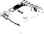
请参阅图3,是本发明的另一较佳具体实施例示意图,本实施例与前述实施例大致相同,而不同之处在于本实施例的盖板30设有连通于该第一出风口32的通风缺口37。通风缺口37至少涵盖该第二发热装置22的中央区域以减少该中央区域的风阻,从而使集中于该中央区域的热能可迅速地散逸而出,一般而言,该第一出风口32接近电子设备2后方的通风开口,因此亦可通过外部的冷空气流入该通风缺口37而进一步地散逸该第二发热装置22中央区域的热能。相比于现有技术存储器单元的中央区域容易积热的现象,本发明的导风罩3因具有通风缺口37而可将第二发热装置22(存储器单元)中央区域的热能迅速散逸。Please refer to FIG. 3 , which is a schematic diagram of another preferred embodiment of the present invention. This embodiment is substantially the same as the previous embodiment, but the difference is that the
由上可知,本发明的导风罩可改善现有缺点,因此具有高度产业利用价值。From the above, it can be seen that the air guide cover of the present invention can improve the existing disadvantages, so it has high industrial application value.
上述的实施例仅为例示性说明本发明的原理及其功效,而非用于限制本发明。任何本领域技术人员均可在不违背本发明的精神及范畴下,对上述实施例进行修饰与变化。因此,本发明的权利保护范围,应如申请专利书列。The above-mentioned embodiments are only for illustrating the principles and effects of the present invention, but not for limiting the present invention. Any person skilled in the art can modify and change the above-mentioned embodiments without departing from the spirit and scope of the present invention. Therefore, the scope of protection of the rights of the present invention should be listed in the patent application.
Claims (12)
Priority Applications (1)
| Application Number | Priority Date | Filing Date | Title |
|---|---|---|---|
| CNA2006101154286ACN101123863A (en) | 2006-08-09 | 2006-08-09 | Wind scooper |
Applications Claiming Priority (1)
| Application Number | Priority Date | Filing Date | Title |
|---|---|---|---|
| CNA2006101154286ACN101123863A (en) | 2006-08-09 | 2006-08-09 | Wind scooper |
Publications (1)
| Publication Number | Publication Date |
|---|---|
| CN101123863Atrue CN101123863A (en) | 2008-02-13 |
Family
ID=39085964
Family Applications (1)
| Application Number | Title | Priority Date | Filing Date |
|---|---|---|---|
| CNA2006101154286APendingCN101123863A (en) | 2006-08-09 | 2006-08-09 | Wind scooper |
Country Status (1)
| Country | Link |
|---|---|
| CN (1) | CN101123863A (en) |
Cited By (11)
| Publication number | Priority date | Publication date | Assignee | Title |
|---|---|---|---|---|
| CN102536852A (en)* | 2010-12-31 | 2012-07-04 | 台达电子工业股份有限公司 | heat sink |
| CN102573399A (en)* | 2010-12-28 | 2012-07-11 | 鸿富锦精密工业(深圳)有限公司 | Electronic device |
| CN103108527A (en)* | 2011-11-15 | 2013-05-15 | 技嘉科技股份有限公司 | Wind scooper and electronic device |
| US8721275B2 (en) | 2010-12-31 | 2014-05-13 | Delta Electronics, Inc. | Heat dissipation device |
| CN103809711A (en)* | 2012-11-12 | 2014-05-21 | 英业达科技有限公司 | Electronic device |
| CN103984396A (en)* | 2014-03-21 | 2014-08-13 | 苏州佳世达光电有限公司 | Electronic device |
| CN105843348A (en)* | 2016-05-19 | 2016-08-10 | 浪潮电子信息产业股份有限公司 | Design method of air guide cover for heat dissipation of board card |
| CN111328227A (en)* | 2020-02-27 | 2020-06-23 | 苏州浪潮智能科技有限公司 | Power supply wind scooper structure capable of realizing optional matching |
| CN111413840A (en)* | 2018-12-18 | 2020-07-14 | 卡西欧计算机株式会社 | Heating device, light source device and projection device |
| CN114126320A (en)* | 2020-08-26 | 2022-03-01 | 鸿富锦精密工业(武汉)有限公司 | Air hood and cooling device |
| CN116266982A (en)* | 2021-12-16 | 2023-06-20 | 台达电子企业管理(上海)有限公司 | Power supply device |
- 2006
- 2006-08-09CNCNA2006101154286Apatent/CN101123863A/enactivePending
Cited By (13)
| Publication number | Priority date | Publication date | Assignee | Title |
|---|---|---|---|---|
| CN102573399A (en)* | 2010-12-28 | 2012-07-11 | 鸿富锦精密工业(深圳)有限公司 | Electronic device |
| CN102536852B (en)* | 2010-12-31 | 2015-04-01 | 台达电子工业股份有限公司 | heat sink |
| US8721275B2 (en) | 2010-12-31 | 2014-05-13 | Delta Electronics, Inc. | Heat dissipation device |
| CN102536852A (en)* | 2010-12-31 | 2012-07-04 | 台达电子工业股份有限公司 | heat sink |
| CN103108527A (en)* | 2011-11-15 | 2013-05-15 | 技嘉科技股份有限公司 | Wind scooper and electronic device |
| CN103809711A (en)* | 2012-11-12 | 2014-05-21 | 英业达科技有限公司 | Electronic device |
| CN103984396A (en)* | 2014-03-21 | 2014-08-13 | 苏州佳世达光电有限公司 | Electronic device |
| CN105843348A (en)* | 2016-05-19 | 2016-08-10 | 浪潮电子信息产业股份有限公司 | Design method of air guide cover for heat dissipation of board card |
| CN111413840A (en)* | 2018-12-18 | 2020-07-14 | 卡西欧计算机株式会社 | Heating device, light source device and projection device |
| CN111413840B (en)* | 2018-12-18 | 2021-12-31 | 卡西欧计算机株式会社 | Heat generating device, light source device, and projection device |
| CN111328227A (en)* | 2020-02-27 | 2020-06-23 | 苏州浪潮智能科技有限公司 | Power supply wind scooper structure capable of realizing optional matching |
| CN114126320A (en)* | 2020-08-26 | 2022-03-01 | 鸿富锦精密工业(武汉)有限公司 | Air hood and cooling device |
| CN116266982A (en)* | 2021-12-16 | 2023-06-20 | 台达电子企业管理(上海)有限公司 | Power supply device |
Similar Documents
| Publication | Publication Date | Title |
|---|---|---|
| CN101123863A (en) | Wind scooper | |
| CN201138463Y (en) | Computer system with wind deflector | |
| CN102763496B (en) | The cooling structure of electronic equipment | |
| CN102573383B (en) | Wind scooper and use the heat abstractor of this wind scooper | |
| CN101998812B (en) | Cooling module | |
| CN103108527B (en) | Wind scooper and electronic device | |
| US20080113607A1 (en) | Wind-guiding cover | |
| CN113031273B (en) | Head-mounted display device and heat dissipation mechanism thereof | |
| CN102387693A (en) | Radiating device and electronic device using same | |
| CN102262428A (en) | Flow dividing type air guide cover | |
| CN102573392A (en) | Air guiding cover and heat dissipation system with same | |
| CN101466240A (en) | Radiating device | |
| CN102279639A (en) | Radiating device and centrifugal fan thereof | |
| CN102854945A (en) | Electronic device | |
| CN102467199A (en) | Electronic device | |
| TWI291321B (en) | Wind-guiding cover | |
| TWI344814B (en) | Case of electronic device | |
| TW201422135A (en) | Electronic device | |
| TW201248371A (en) | Heat dissipating system for computer | |
| CN104105379B (en) | Heat radiation assembly and display card module | |
| CN112462900B (en) | Wind scooper structure, heat dissipation device with same and server | |
| CN101907912B (en) | Electronic equipment | |
| CN209028558U (en) | A cooling device in a computer case | |
| CN102279629A (en) | Computer shell | |
| CN102568760B (en) | Fin-inserting type radiator and heat radiating device with same |
Legal Events
| Date | Code | Title | Description |
|---|---|---|---|
| C06 | Publication | ||
| PB01 | Publication | ||
| C10 | Entry into substantive examination | ||
| SE01 | Entry into force of request for substantive examination | ||
| C02 | Deemed withdrawal of patent application after publication (patent law 2001) | ||
| WD01 | Invention patent application deemed withdrawn after publication |