CN101123341A - Laser light source device and projector equipped with same - Google Patents
Laser light source device and projector equipped with sameDownload PDFInfo
- Publication number
- CN101123341A CN101123341ACNA2007101418058ACN200710141805ACN101123341ACN 101123341 ACN101123341 ACN 101123341ACN A2007101418058 ACNA2007101418058 ACN A2007101418058ACN 200710141805 ACN200710141805 ACN 200710141805ACN 101123341 ACN101123341 ACN 101123341A
- Authority
- CN
- China
- Prior art keywords
- laser light
- wavelength
- aforementioned
- laser
- light source
- Prior art date
- Legal status (The legal status is an assumption and is not a legal conclusion. Google has not performed a legal analysis and makes no representation as to the accuracy of the status listed.)
- Granted
Links
- 238000006243chemical reactionMethods0.000claimsabstractdescription232
- 230000005284excitationEffects0.000claimsabstractdescription151
- 230000003287optical effectEffects0.000claimsdescription34
- 239000004065semiconductorSubstances0.000claimsdescription24
- 230000005540biological transmissionEffects0.000claimsdescription13
- 239000000463materialSubstances0.000claimsdescription13
- 238000003475laminationMethods0.000claimsdescription3
- 230000000737periodic effectEffects0.000claimsdescription2
- 239000007787solidSubstances0.000claimsdescription2
- 239000010408filmSubstances0.000description144
- 238000002834transmittanceMethods0.000description25
- 239000000758substrateSubstances0.000description23
- 239000004973liquid crystal related substanceSubstances0.000description18
- 238000010586diagramMethods0.000description14
- 239000011521glassSubstances0.000description11
- 230000004048modificationEffects0.000description9
- 238000012986modificationMethods0.000description9
- 239000000284extractSubstances0.000description8
- 230000006872improvementEffects0.000description8
- 230000000694effectsEffects0.000description6
- 230000008859changeEffects0.000description5
- 238000004519manufacturing processMethods0.000description5
- 230000010287polarizationEffects0.000description5
- 230000009467reductionEffects0.000description4
- 238000005229chemical vapour depositionMethods0.000description3
- 238000000926separation methodMethods0.000description3
- 239000010409thin filmSubstances0.000description3
- 229910013641LiNbO 3Inorganic materials0.000description2
- 239000003086colorantSubstances0.000description2
- 239000000470constituentSubstances0.000description2
- 238000001816coolingMethods0.000description2
- 239000013078crystalSubstances0.000description2
- 238000001514detection methodMethods0.000description2
- 238000000034methodMethods0.000description2
- 239000012788optical filmSubstances0.000description2
- 238000012545processingMethods0.000description2
- 230000003595spectral effectEffects0.000description2
- 230000007704transitionEffects0.000description2
- YCZZNGRKFVBLDL-UHFFFAOYSA-N2-[(2-methoxyphenyl)methylidene]propanedinitrileChemical compoundCOC1=CC=CC=C1C=C(C#N)C#NYCZZNGRKFVBLDL-UHFFFAOYSA-N0.000description1
- XTTIQGSLJBWVIV-UHFFFAOYSA-N2-methyl-4-nitroanilineChemical compoundCC1=CC([N+]([O-])=O)=CC=C1NXTTIQGSLJBWVIV-UHFFFAOYSA-N0.000description1
- XJCVRTZCHMZPBD-UHFFFAOYSA-N3-nitroanilineChemical compoundNC1=CC=CC([N+]([O-])=O)=C1XJCVRTZCHMZPBD-UHFFFAOYSA-N0.000description1
- WSMQKESQZFQMFW-UHFFFAOYSA-N5-methyl-pyrazole-3-carboxylic acidChemical compoundCC1=CC(C(O)=O)=NN1WSMQKESQZFQMFW-UHFFFAOYSA-N0.000description1
- DQFBYFPFKXHELB-UHFFFAOYSA-NChalconeNatural productsC=1C=CC=CC=1C(=O)C=CC1=CC=CC=C1DQFBYFPFKXHELB-UHFFFAOYSA-N0.000description1
- WTKZEGDFNFYCGP-UHFFFAOYSA-NPyrazoleChemical compoundC=1C=NNC=1WTKZEGDFNFYCGP-UHFFFAOYSA-N0.000description1
- 229910004298SiO 2Inorganic materials0.000description1
- PPBRXRYQALVLMV-UHFFFAOYSA-NStyreneNatural productsC=CC1=CC=CC=C1PPBRXRYQALVLMV-UHFFFAOYSA-N0.000description1
- 229910010413TiO 2Inorganic materials0.000description1
- 230000003667anti-reflective effectEffects0.000description1
- -1chalcone styrene ketoneChemical class0.000description1
- 235000005513chalconesNutrition0.000description1
- 238000004891communicationMethods0.000description1
- 239000006185dispersionSubstances0.000description1
- GQYHUHYESMUTHG-UHFFFAOYSA-Nlithium niobateChemical compound[Li+].[O-][Nb](=O)=OGQYHUHYESMUTHG-UHFFFAOYSA-N0.000description1
- 238000005259measurementMethods0.000description1
- 230000007246mechanismEffects0.000description1
- 239000000203mixtureSubstances0.000description1
- NXIHUWPAXYATMI-UHFFFAOYSA-Nn-(methoxymethyl)-4-nitroanilineChemical compoundCOCNC1=CC=C([N+]([O-])=O)C=C1NXIHUWPAXYATMI-UHFFFAOYSA-N0.000description1
- 125000006501nitrophenyl groupChemical group0.000description1
- 230000005693optoelectronicsEffects0.000description1
- 239000011368organic materialSubstances0.000description1
- 230000010355oscillationEffects0.000description1
- 229910021420polycrystalline siliconInorganic materials0.000description1
- 229920000642polymerPolymers0.000description1
- 229920005591polysiliconPolymers0.000description1
- 239000011347resinSubstances0.000description1
- 229920005989resinPolymers0.000description1
- 229910052594sapphireInorganic materials0.000description1
- 239000010980sapphireSubstances0.000description1
- 230000005236sound signalEffects0.000description1
Images


Landscapes
- Optical Modulation, Optical Deflection, Nonlinear Optics, Optical Demodulation, Optical Logic Elements (AREA)
- Projection Apparatus (AREA)
- Semiconductor Lasers (AREA)
Abstract
Translated fromChinese
Description
Translated fromChinese技术领域technical field
本发明,涉及射出激光的激光光源装置,及具备有该激光光源装置的投影机。The present invention relates to a laser light source device that emits laser light, and a projector including the laser light source device.
背景技术Background technique
近年来,在光通信,光应用测定,光显示等的光电子领域中,广泛使用对半导体激光光源的激发(oscillation)光进行波长变换而采用的激光光源装置。作为如此的激光光源装置,已知如下二次谐波光发生装置,该装置:具备在单端面形成镜体结构及在其对向面形成无反射结构的半导体激光光源,和在其光激发面形成镜体结构及在其对向面形成无反射结构的非线性光学构件;并以激光光源装置和非线性光学构件的镜体结构间形成谐振器结构,可以发生绿光、蓝光(例如,参照专利文献1)。In recent years, in optoelectronic fields such as optical communication, optical application measurement, and optical display, laser light source devices employing wavelength conversion of excitation (oscillation) light of a semiconductor laser light source have been widely used. As such a laser light source device, there is known a second harmonic light generating device having a semiconductor laser light source with a mirror body structure formed on a single end surface and a non-reflective structure formed on its opposite surface, and Form a mirror body structure and form a non-reflective nonlinear optical member on its opposite surface; and form a resonator structure between the laser light source device and the mirror body structure of the nonlinear optical member, green light and blue light can be generated (for example, refer to Patent Document 1).
并且,为了使波长幅度窄的激光束稳定而进行供给,提出了如下外部谐振型激光器,该激光器:具备射出预定的波长的激光的半导体激光激发器,和使从激光激发器所射出的激光进行谐振的外部谐振器;在外部谐振器内具备光聚合物体积全息图,光聚合物体积全息图使从激光激发器所射出的激光发生衍射而入射于谐振器内的光学系统,并使预定的波长的激光选择性地进行透射而射出于外部(例如,参照专利文献2)。In addition, in order to stably supply a laser beam with a narrow wavelength width, an external resonance type laser has been proposed which includes a semiconductor laser exciter that emits laser light of a predetermined wavelength, and that makes the laser beam emitted from the laser exciter A resonant external resonator; a photopolymer volume hologram is provided in the external resonator, and the photopolymer volume hologram diffracts the laser light emitted from the laser exciter and enters the optical system in the resonator, and makes the predetermined Laser light of a wavelength is selectively transmitted and emitted to the outside (for example, refer to Patent Document 2).
【专利文献1】特许第3300429号公报[Patent Document 1] Patent No. 3300429
【专利文献2】特开2001-284718号公报[Patent Document 2] JP-A-2001-284718
但是,如记载于专利文献1的现有的二次谐波光发生装置,因为不使激光窄频带化,所以存在如下问题:由于温度变化而半导体激光光源的激发波长发生变动,或者相对于波长变换元件(与前述非线性光学构件相同)的变换波长的允许幅度,从光源所激发的激光的激发波长幅度宽,不能进行波长变换的波段的光多,变换效率低。However, since the conventional second harmonic light generator described in Patent Document 1 does not narrow the frequency band of the laser light, there is a problem that the excitation wavelength of the semiconductor laser light source fluctuates due to temperature changes, or the excitation wavelength of the semiconductor laser light source varies with the wavelength. The permissible range of the conversion wavelength of the conversion element (the same as the aforementioned nonlinear optical member) is wider than the excitation wavelength range of the laser light excited from the light source, and there are many wavelengths of light that cannot be converted into wavelengths, and the conversion efficiency is low.
另一方面,用于记载于专利文献2的外部谐振型激光器中的光聚合物体积全息图,例如,为在树脂中层状地形成多个折射率不同的干涉图形,使激发波长的激光窄频带化而进行反射的元件,可谓能够简单地构成外部谐振型激光器,为高价的元件。由此,有制造成本升高的问题。On the other hand, in the photopolymer volume hologram used in the external resonance type laser described in
发明内容Contents of the invention
本发明,鉴于如此的情况所作出,目的在于提供能良好地射出激光,并能低成本化及小型化的激光光源装置,及具备有该激光光源装置的投影机。The present invention has been made in view of such circumstances, and an object of the present invention is to provide a laser light source device that can emit laser light well, and that can be reduced in cost and size, and a projector including the laser light source device.
本发明中的激光光源装置,具备:激发预定的波长的激光的激光光源,对从前述激光光源所射出的激光进行反射而形成谐振器的镜体,和配设于前述激光光源与前述镜体之间、对从前述激光光源所射出的激发波长的激光进行变换而射出变换波长的激光的波长变换元件;其特征在于:前述镜体,包括形成于前述波长变换元件的射出侧的表面的、具有对前述激发波长的激光进行反射而使前述变换波长的激光进行透射的特性的电介质多层膜;在前述波长变换元件的入射侧的表面,形成有至少在前述激发波长附近具有带通特性的带通滤波器多层膜。The laser light source device in the present invention comprises: a laser light source that excites laser light of a predetermined wavelength, a mirror that reflects laser light emitted from the laser light source to form a resonator, and a mirror body that is arranged between the laser light source and the mirror body. Among them, a wavelength conversion element that converts the laser light of the excitation wavelength emitted from the aforementioned laser light source and emits the laser light of the converted wavelength; it is characterized in that the aforementioned mirror body includes a surface formed on the emission side of the aforementioned wavelength conversion element, A dielectric multilayer film having the characteristics of reflecting the laser light of the excitation wavelength and transmitting the laser light of the converted wavelength; on the surface of the incident side of the wavelength conversion element, a film having a band-pass characteristic at least in the vicinity of the excitation wavelength is formed. Bandpass filter multilayer film.
若依照于该构成,则在形成于波长变换元件的带通滤波器多层膜中从激光光源所射出的激光的激发波长可窄频带化为半值幅度1nm以下。由此,波长变换元件中的波长变换的变换效率提高,并且即使由于使用环境的温度变化等而在激光光源的激发波长中发生了变动,也能够总是使一定波长的激光,从激光光源装置射出。According to this configuration, the excitation wavelength of the laser light emitted from the laser light source in the bandpass filter multilayer film formed on the wavelength conversion element can be narrowed to a half-value width of 1 nm or less. As a result, the conversion efficiency of the wavelength conversion in the wavelength conversion element is improved, and even if the excitation wavelength of the laser light source fluctuates due to temperature changes in the use environment, etc., it is always possible to use laser light with a certain wavelength from the laser light source device. shoot out.
并且,因为镜体具有对激发波长的激光进行反射,并使变换波长的激光进行透射的特性,所以能够一边将激光光源的激发光封闭在谐振器的内部,一边高效地取出通过波长变换元件进行了波长变换的激光。进而,通过将带通滤波器多层膜及镜体,形成于波长变换元件的入射侧的表面及射出侧的表面,可得到减少了构成部件个数、并且低成本化及小型化了的激光光源装置。In addition, since the mirror body has the characteristics of reflecting the laser light of the excitation wavelength and transmitting the laser light of the converted wavelength, the excitation light of the laser light source can be efficiently taken out through the wavelength conversion element while confining it inside the resonator. wavelength-converted laser light. Furthermore, by forming the multilayer film of the bandpass filter and the mirror body on the incident side surface and the exiting side surface of the wavelength conversion element, it is possible to obtain a laser beam with a reduced number of components and a reduced cost and size. light source device.
并且,本发明中的激光光源装置,具备:激发预定的波长的激光的激光光源,对从前述激光光源所射出的激光进行反射而形成谐振器的镜体,和配设于前述激光光源与前述镜体之间、对从前述激光光源所射出的激发波长的激光进行变换而射出变换波长的激光的波长变换元件;其特征在于:在前述激光光源与前述波长变换元件之间,还具备形成有至少在前述激发波长附近具有带通特性的带通滤波器多层膜的带通滤波器;前述镜体,包括形成于前述波长变换元件的射出侧的表面的、具有对前述激发波长的激光进行反射并使前述变换波长的激光进行透射的特性的电介质多层膜。And, the laser light source device among the present invention, has: the laser light source that excites the laser light of predetermined wavelength, reflects the laser light emitted from the aforementioned laser light source to form a resonator mirror body, and is arranged between the aforementioned laser light source and the aforementioned Between the mirror bodies, the wavelength conversion element for converting the laser light of the excitation wavelength emitted from the aforementioned laser light source to emit the laser light of the converted wavelength; it is characterized in that: between the aforementioned laser light source and the aforementioned wavelength conversion element, there is also a wavelength conversion element formed with A band-pass filter of a band-pass filter multilayer film having a band-pass characteristic at least near the excitation wavelength; A dielectric multilayer film that reflects and transmits the wavelength-converted laser light.
若依照于该构成,则因为在激发预定的波长的激光的激光光源,和在射出侧的表面形成有包括具有对激发波长的激光进行反射并使变换波长的激光进行透射的特性的电介质多层膜的镜体、对从激光光源所射出的激光的激发波长进行变换而射出变换波长的激光的波长变换元件之间,具备形成有在前述激发波长附近具有带通特性的带通滤波器多层膜的带通滤波器,所以可以对波长变换元件和带通滤波器独立地进行各种特性的调整,能够期待激发效率及成品率的提高。According to this structure, since the laser light source that excites laser light of a predetermined wavelength and the surface on the exit side are formed with a dielectric multilayer having the characteristics of reflecting the laser light of the excitation wavelength and transmitting the laser light of the converted wavelength Between the mirror body of the film and the wavelength conversion element that converts the excitation wavelength of the laser light emitted from the laser light source and emits the laser light with the converted wavelength, there is a multilayer band-pass filter formed with band-pass characteristics near the excitation wavelength. Since it is a band-pass filter of a film, various characteristics can be independently adjusted for the wavelength conversion element and the band-pass filter, and improvements in excitation efficiency and yield can be expected.
进而,因为通过使镜体具有对激发波长进行反射并使变换波长进行透射的特性,一边将激光光源的激发光封闭在谐振器的内部,一边使通过波长变换元件进行了波长变换的激光高效地取出,所以可得到变换效率提高了的激光光源装置。Furthermore, because the mirror body has the characteristics of reflecting the excitation wavelength and transmitting the converted wavelength, while confining the excitation light of the laser light source inside the resonator, the laser light whose wavelength has been converted by the wavelength conversion element is efficiently Therefore, a laser light source device with improved conversion efficiency can be obtained.
并且,本发明中的激光光源装置,具备:激发预定的波长的激光的激光光源,对从前述激光光源所射出的激光进行反射而形成谐振器的镜体,和配设于前述激光光源与前述镜体之间、对从前述激光光源所射出的激发波长的激光进行变换而射出变换波长的激光的波长变换元件;其特征在于:前述镜体,包括形成有具有对前述激发波长的激光进行反射并使前述变换波长的激光进行透射的特性的电介质多层膜的透明构件,配设于前述波长变换元件的射出侧;在前述波长变换元件的入射侧的表面,形成有至少在前述激发波长附近具有带通特性的带通滤波器多层膜。And, the laser light source device among the present invention, has: the laser light source that excites the laser light of predetermined wavelength, reflects the laser light emitted from the aforementioned laser light source to form a resonator mirror body, and is arranged between the aforementioned laser light source and the aforementioned Between the mirror bodies, the wavelength conversion element for converting the laser light of the excitation wavelength emitted from the aforementioned laser light source to emit the laser light of the converted wavelength; it is characterized in that: the aforementioned mirror body includes a laser beam having a reflective function for the aforementioned excitation wavelength laser light. The transparent member of the dielectric multilayer film having the characteristic of transmitting the laser light of the above-mentioned wavelength conversion is arranged on the output side of the above-mentioned wavelength conversion element; Bandpass filter multilayer film with bandpass characteristics.
若依照于该构成,则因为在激发预定的波长的激光的激光光源,和对从激光光源所射出的激发波长的激光进行变换而射出变换波长的激光的波长变换元件之间,具备形成有带通滤波器多层膜的带通滤波器,所以可以对波长变换元件和带通滤波器独立地进行各种特性的调整,能够期待激发效率及成品率的提高。According to this configuration, a band is formed between the laser light source that excites laser light of a predetermined wavelength and the wavelength conversion element that converts the laser light of the excitation wavelength emitted from the laser light source to emit laser light with a converted wavelength. Since the pass filter is a multilayer bandpass filter, various characteristics can be adjusted independently of the wavelength conversion element and the bandpass filter, and improvements in excitation efficiency and yield can be expected.
进而,因为通过镜体具有对激发波长的激光进行反射、并使变换波长的激光进行透射的特性,一边将激光光源的激发光封闭在谐振器的内部,一边使通过波长变换元件进行了波长变换的激光高效地取出,所以可得到变换效率提高了的激光光源装置。Furthermore, because the pass mirror body has the characteristics of reflecting the laser light of the excitation wavelength and transmitting the laser light of the converted wavelength, while confining the excitation light of the laser light source inside the resonator, the wavelength conversion is performed by the pass wavelength conversion element. The laser light is extracted efficiently, so a laser light source device with improved conversion efficiency can be obtained.
并且,本发明中的激光光源装置,具备:激发预定的波长的激光的激光光源,对从前述激光光源所射出的激光进行反射而形成谐振器的镜体,和配设于前述激光光源与前述镜体之间、对从前述激光光源所射出的激发波长的激光进行变换而射出变换波长的激光的波长变换元件;其特征在于:前述镜体,包括形成有具有对前述激发波长的激光进行反射并使前述变换波长的激光进行透射的特性的电介质多层膜的透明构件,配设于前述波长变换元件的射出侧;在前述激光光源与前述波长变换元件之间,还具备形成有至少在前述激发波长附近具有带通特性的带通滤波器多层膜的带通滤波器。And, the laser light source device among the present invention, has: the laser light source that excites the laser light of predetermined wavelength, reflects the laser light emitted from the aforementioned laser light source to form a resonator mirror body, and is arranged between the aforementioned laser light source and the aforementioned Between the mirror bodies, the wavelength conversion element for converting the laser light of the excitation wavelength emitted from the aforementioned laser light source to emit the laser light of the converted wavelength; it is characterized in that: the aforementioned mirror body includes a laser beam having a reflective function for the aforementioned excitation wavelength laser light. The transparent member of the dielectric multilayer film having the characteristic of transmitting the wavelength-converted laser light is disposed on the emission side of the wavelength conversion element; between the laser light source and the wavelength conversion element, at least the aforementioned A bandpass filter with a bandpass characteristic near the excitation wavelength Multilayer film bandpass filter.
若依照于该构成,则因为具备激发预定的波长的激光的激光光源,对从激光光源所射出的激发波长的激光进行变换而射出变换波长的激光的波长变换元件,和配设于波长变换元件的射出侧的、包括形成有具有对激发波长的激光进行反射并使变换波长的激光进行透射的特性的电介质多层膜的透明构件的镜体,并在激光光源与波长变换元件之间,或镜体与波长变换元件之间具备形成有带通滤波器多层膜的带通滤波器,所以可以对波长变换元件,镜体,带通滤波器独立地进行各种特性的调整,能够期待激发效率及成品率的提高。According to this structure, since it is equipped with a laser light source that excites laser light with a predetermined wavelength, a wavelength conversion element that converts laser light with an excitation wavelength emitted from the laser light source to emit laser light with a converted wavelength, and a wavelength conversion element disposed on the wavelength conversion element On the emission side, a mirror body including a transparent member formed with a dielectric multilayer film having the characteristics of reflecting the laser light of the excitation wavelength and transmitting the laser light of the converted wavelength, and between the laser light source and the wavelength conversion element, or There is a band-pass filter with a band-pass filter multilayer film formed between the mirror body and the wavelength conversion element, so that various characteristics can be independently adjusted for the wavelength conversion element, mirror body, and band-pass filter, and excitation can be expected. Improvement in efficiency and yield.
进而,因为通过使镜体具有对激发波长的激光进行反射,并使变换波长的激光进行透射的特性,一边将激光光源的激发光封闭在谐振器的内部,一边使通过波长变换元件进行了波长变换的激光高效地取出,所以可得到变换效率提高了的激光光源装置。Furthermore, because the mirror body has the characteristics of reflecting the laser light of the excitation wavelength and transmitting the laser light of the converted wavelength, while the excitation light of the laser light source is enclosed in the resonator, the wavelength of the laser light passing through the wavelength conversion element is made Since the converted laser light is efficiently extracted, a laser light source device with improved conversion efficiency can be obtained.
并且,本发明中的激光光源装置,具备:激发预定的波长的激光的激光光源,对从前述激光光源所射出的激光进行反射而形成谐振器的镜体,和配设于前述激光光源与前述镜体之间、对从前述激光光源所射出的激发波长的激光进行变换而射出变换波长的激光的波长变换元件;其特征在于:前述镜体,包括形成有具有对前述激发波长进行反射并使前述变换波长进行透射的特性的电介质多层膜的透明构件,配设于前述波长变换元件的射出侧;在前述镜体与前述波长变换元件之间,还具备形成有至少在前述激发波长附近具有带通特性的带通滤波器多层膜的带通滤波器。And, the laser light source device among the present invention, has: the laser light source that excites the laser light of predetermined wavelength, reflects the laser light emitted from the aforementioned laser light source to form a resonator mirror body, and is arranged between the aforementioned laser light source and the aforementioned Between the mirror bodies, a wavelength conversion element that converts the laser light of the excitation wavelength emitted from the aforementioned laser light source and emits the laser light of the converted wavelength; it is characterized in that: the aforementioned mirror body includes a structure that reflects the aforementioned excitation wavelength and enables The transparent member of the dielectric multilayer film with the characteristic of converting the wavelength to transmit is arranged on the output side of the wavelength conversion element; Band-pass filter with band-pass characteristics Multilayer film band-pass filter.
若依照于该构成,则因为具备激发预定的波长的激光的激光光源,对从激光光源所射出的激发波长的激光进行变换而射出变换波长的激光的波长变换元件,和配设于波长变换元件的射出侧的、包括形成有具有对激发波长的激光进行反射并使变换波长的激光进行透射的特性的电介质多层膜的透明构件的镜体,并在激光光源与波长变换元件之间,或镜体与波长变换元件之间具备形成有带通滤波器多层膜的带通滤波器,所以可以对波长变换元件,镜体,带通滤波器独立地进行各种特性的调整,能够期待激发效率及成品率的提高。According to this structure, since it is equipped with a laser light source that excites laser light with a predetermined wavelength, a wavelength conversion element that converts laser light with an excitation wavelength emitted from the laser light source to emit laser light with a converted wavelength, and a wavelength conversion element disposed on the wavelength conversion element On the emission side, a mirror body including a transparent member formed with a dielectric multilayer film having the characteristics of reflecting the laser light of the excitation wavelength and transmitting the laser light of the converted wavelength, and between the laser light source and the wavelength conversion element, or There is a band-pass filter with a band-pass filter multilayer film formed between the mirror body and the wavelength conversion element, so that various characteristics can be independently adjusted for the wavelength conversion element, mirror body, and band-pass filter, and excitation can be expected. Improvement in efficiency and yield.
进而,因为通过使镜体具有对激发波长的激光进行反射,并使变换波长的激光进行透射的特性,一边将激光光源的激发光封闭在谐振器的内部,一边使通过波长变换元件进行了波长变换的激光高效地取出,所以可得到变换效率提高了的激光光源装置。Furthermore, because the mirror body has the characteristics of reflecting the laser light of the excitation wavelength and transmitting the laser light of the converted wavelength, while the excitation light of the laser light source is enclosed in the resonator, the wavelength of the laser light passing through the wavelength conversion element is made Since the converted laser light is efficiently extracted, a laser light source device with improved conversion efficiency can be obtained.
并且,本发明中的激光光源装置,优选:带通滤波器,能相对于从前述激光光源所射出的激光倾斜。Furthermore, in the laser light source device of the present invention, it is preferable that the bandpass filter is tiltable with respect to the laser light emitted from the laser light source.
若依照于该构成,则因为使激发波长的激光窄频带化的带通滤波器,能相对于激光光源的激光射出面倾斜地构成,所以通过改变激光与带通滤波器的中心轴的角度,即入射于带通滤波器的激光相对于带通滤波器的中心轴的入射角度,能够改变对带通滤波器进行透射的激光的波长。由此,即使由于带通滤波器的制造误差等而在透射光的波长中产生偏差,也可以进行微调整,使之与波长变换元件的变换波长相对应,使激光的激发效率及波长变换效率进一步提高,能够从激光光源装置,射出更加良好的激光。According to this structure, since the band-pass filter for narrowing the frequency band of the laser light of the excitation wavelength can be configured obliquely with respect to the laser light emitting surface of the laser light source, by changing the angle of the central axis of the laser light and the band-pass filter, That is, the incident angle of the laser beam incident on the band-pass filter with respect to the central axis of the band-pass filter can change the wavelength of the laser beam passing through the band-pass filter. In this way, even if there is a deviation in the wavelength of the transmitted light due to manufacturing errors of the band-pass filter, etc., it can be finely adjusted to correspond to the converted wavelength of the wavelength conversion element, and the excitation efficiency and wavelength conversion efficiency of the laser light can be improved. With further improvement, better laser light can be emitted from the laser light source device.
并且,本发明中的激光光源装置,优选:前述带通滤波器多层膜,还具有对前述变换波长的激光进行反射的特性。In addition, in the laser light source device of the present invention, it is preferable that the bandpass filter multilayer film further has a property of reflecting the wavelength-converted laser light.
若依照于该构成,则因为带通滤波器多层膜,具有对变换波长的激光进行反射的特性,所以由镜体的电介质多层膜所反射的、由反馈入射于波长变换元件的激发波长的激光通过波长变换元件所生成的变换光,在带通滤波器多层膜中被反射,通过波长变换元件而从激光光源装置所射出。由此,由返回于激光光源的反馈光所生成的变换光也能够有效地从激光光源装置取出,能够使变换光的输出提高。According to this structure, since the multilayer film of the bandpass filter has the characteristic of reflecting the laser light of the converted wavelength, the excitation wavelength reflected by the dielectric multilayer film of the mirror body and incident on the wavelength conversion element by feedback The converted light generated by the laser light passing through the wavelength conversion element is reflected by the band-pass filter multilayer film, passes through the wavelength conversion element, and is emitted from the laser light source device. Accordingly, the converted light generated by the feedback light returned to the laser light source can also be efficiently extracted from the laser light source device, and the output of the converted light can be improved.
并且,本发明中的激光光源装置,优选:前述带通滤波器多层膜,还具有使前述变换波长的激光进行透射的特性。In addition, in the laser light source device of the present invention, it is preferable that the bandpass filter multilayer film further has a property of transmitting the wavelength-converted laser light.
若依照于该构成,则因为带通滤波器多层膜,具有使变换波长的激光进行透射的特性,所以通过波长变换元件所生成的变换光,在带通滤波器多层膜中可透射,从激光光源装置射出。由此,能够有效地将变换光从激光光源装置取出,能够使变换光的输出提高。According to this configuration, since the band-pass filter multilayer film has the property of transmitting the wavelength-converted laser light, the converted light generated by the wavelength conversion element can be transmitted through the band-pass filter multilayer film, Emitted from the laser light source device. Thereby, the converted light can be efficiently extracted from the laser light source device, and the output of the converted light can be improved.
并且,本发明中的激光光源装置,优选:前述带通滤波器多层膜,交替地叠层高折射率层H与低折射率层L,以前述激发波长为λ,光学膜厚从前述波长变换元件侧按顺序为:0.236λH,0.355λL,0.207λH,0.203λL,(0.25λH,0.25λL)n,0.5λH,(0.25λL,0.25λH)n,0.266λL,0.255λH,0.248λL,0.301λH,0.631λL。其中,n为3~10的范围的值,表示将括弧内的层重复进行叠层的重复次数。In addition, in the laser light source device of the present invention, it is preferable that the band-pass filter multilayer film alternately laminates high-refractive-index layers H and low-refractive-index layers L, with the aforementioned excitation wavelength as λ, and the optical film thickness from the aforementioned wavelength to λ. The conversion element side is in order: 0.236λH, 0.355λL, 0.207λH, 0.203λL, (0.25λH, 0.25λL)n, 0.5λH, (0.25λL, 0.25λH)n, 0.266λL, 0.255λH, 0.248λL, 0.301 λH, 0.631λL. However, n is a value in the range of 3 to 10, and represents the number of repetitions of lamination of layers enclosed in parentheses.
若依照于该构成,则由于带通滤波器多层膜,如前述地交替叠层高折射率层H与低折射率层L所形成,在激发波长附近具有带通特性,能使从激光光源所射出的激光的激发波长窄频带化为半值幅度1nm以下。由此,波长变换元件中的波长变换的变换效率提高,并且即使由于使用环境的温度变化等而在激光光源的激发波长中发生了变动,也能够总是使一定波长的激光,从激光光源装置射出。还有,形成有带通滤波器多层膜的带通滤波器中,构成带通滤波器的透明基板相对于透射波长的透射率越高则透射波长的损失就越少,激光光源装置的变换效率越发提高。According to this constitution, since the bandpass filter multilayer film is formed by alternately stacking the high refractive index layer H and the low refractive index layer L as described above, it has a bandpass characteristic near the excitation wavelength, and can make the laser light source The excitation wavelength of the emitted laser light is narrowed to a half-value width of 1 nm or less. As a result, the conversion efficiency of the wavelength conversion in the wavelength conversion element is improved, and even if the excitation wavelength of the laser light source fluctuates due to temperature changes in the use environment, etc., it is always possible to use laser light with a certain wavelength from the laser light source device. shoot out. In addition, in the band-pass filter formed with the band-pass filter multilayer film, the higher the transmittance of the transparent substrate constituting the band-pass filter with respect to the transmission wavelength, the less the loss of the transmission wavelength, and the conversion of the laser light source device Efficiency is increasing.
并且,本发明中的激光光源装置,优选:形成前述镜体的透明构件,由对于前述变换波长具有80%以上的透射率、并且对于前述激发波长具有20%以下的透射率的材料构成。In addition, in the laser light source device of the present invention, it is preferable that the transparent member forming the mirror body is made of a material having a transmittance of 80% or more for the conversion wavelength and a transmittance of 20% or less for the excitation wavelength.
若依照于该构成,则形成有电介质多层膜的镜体,由于构成镜体的透明构件,由对于变换波长具有80%以上的透射率并且对于激发波长具有20%以下的透射率的材料构成,通过对未以镜体部反射完全的激发光由构件内部进行吸收,能够防止从激光光源装置向外部射出激发光。由此,可得到安全性进一步提高了的激光光源装置。According to this configuration, the mirror body on which the dielectric multilayer film is formed is made of a material having a transmittance of 80% or more with respect to the conversion wavelength and a transmittance of 20% or less with respect to the excitation wavelength because of the transparent member constituting the mirror body. Therefore, by absorbing the excitation light not completely reflected by the mirror body inside the member, it is possible to prevent the excitation light from being emitted from the laser light source device to the outside. Thereby, a laser light source device with further improved safety can be obtained.
并且,本发明中的激光光源装置,优选:在前述波长变换元件的入射侧表面,具有使前述激发波长的激光进行透射并对前述变换波长的激光进行反射的特性的电介质多层膜。In addition, in the laser light source device of the present invention, it is preferable that a dielectric multilayer film has a characteristic of transmitting laser light of the excitation wavelength and reflecting laser light of the converted wavelength on the incident side surface of the wavelength conversion element.
若依照于该构成,则因为形成于波长变换元件的激光光源侧的入射面的电介质多层膜,具有对变换波长的激光进行反射的特性,所以由镜体的电介质多层膜所反射的、由反馈入射于波长变换元件的变换波长的激光通过波长变换元件所生成的变换光,在波长变换元件的电介质多层膜中被反射,通过波长变换元件而从激光光源装置所射出。由此,由返回于激光光源的反馈光所生成的变换光也能够有效地从激光光源装置取出,能够使变换光的输出提高。According to this structure, since the dielectric multilayer film formed on the incident surface of the laser light source side of the wavelength conversion element has the characteristic of reflecting the laser light of the converted wavelength, the reflected by the dielectric multilayer film of the mirror body, The converted light generated by the wavelength-converted laser light incident on the wavelength conversion element in feedback passes through the wavelength conversion element, is reflected by the dielectric multilayer film of the wavelength conversion element, passes through the wavelength conversion element, and is emitted from the laser light source device. Accordingly, the converted light generated by the feedback light returned to the laser light source can also be efficiently extracted from the laser light source device, and the output of the converted light can be improved.
本发明中的激光光源装置,优选:前述激光光源,为端面发光型半导体激光器,面发光型半导体激光器或半导体受激固体激光器之中的任何类型。The laser light source device in the present invention is preferably: the aforementioned laser light source is any type of end-emitting semiconductor laser, surface-emitting semiconductor laser or semiconductor excited solid-state laser.
若依照于该构成,则通过使激光光源,为端面发光型半导体激光器,面发光型半导体激光器或半导体受激固体激光器之中的任何类型,可得到小型而高效的激光光源装置。According to this configuration, a small and efficient laser light source device can be obtained by using any type of end surface emitting semiconductor laser, surface emitting semiconductor laser or semiconductor excited solid state laser as the laser light source.
并且,本发明中的激光光源装置,优选:前述波长变换元件,是具有周期性极化反相结构的二次谐波发生元件。Furthermore, in the laser light source device of the present invention, it is preferable that the aforementioned wavelength converting element is a second harmonic generating element having a periodically polarized anti-phase structure.
若依照于该构成,则由于构成激光光源装置的波长变换元件是二次谐波发生元件,能够由从激光光源所射出的近红外区域的激光生成被窄频带化了的激光(单色可见光)。尤其是,能够容易地得到以激光二极管所难以得到的绿色激光。According to this configuration, since the wavelength conversion element constituting the laser light source device is a second harmonic wave generating element, it is possible to generate narrow-band laser light (monochromatic visible light) from the laser light in the near-infrared region emitted from the laser light source. . In particular, green laser light, which is difficult to obtain with laser diodes, can be easily obtained.
本发明中的投影机,具备:射出激光的激光光源装置,相应于图像信息对从前述激光光源装置所射出的激光进行调制的光调制元件,和射出前述调制了的激光的投影光学系统;其特征在于:前述激光光源装置,是如上述的激光光源装置。The projector in the present invention includes: a laser light source device for emitting laser light, a light modulation element for modulating the laser light emitted from the laser light source device according to image information, and a projection optical system for emitting the modulated laser light; It is characterized in that the aforementioned laser light source device is the above-mentioned laser light source device.
若依照于该构成,则采用了如上述的激光光源装置的投影机,因为红绿蓝的三原色的激光光源装置独立,所以不需要色分离等的滤色器,因为从激光光源装置所射出的激光为直线偏振光故偏振变换元件变得不需要,所以可得到简化了的光学机构。由此,可得到能低成本化及小型化的投影机。并且,因为从激光光源装置可射出激发效率及波长变换效率提高了的激光,所以能够提供具有宽的色再现范围的投影机。According to this structure, the projector employing the above-mentioned laser light source device, since the laser light source devices of the three primary colors of red, green and blue are independent, color filters such as color separation are not needed, because the laser light emitted from the laser light source device Since laser light is linearly polarized light, a polarization conversion element is unnecessary, so a simplified optical mechanism can be obtained. Thereby, a projector capable of cost reduction and miniaturization can be obtained. Furthermore, since laser light with improved excitation efficiency and wavelength conversion efficiency can be emitted from the laser light source device, a projector having a wide color reproduction range can be provided.
附图说明Description of drawings
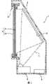
图1是本发明中的背投型投影机的侧剖面图。FIG. 1 is a side sectional view of a rear projection type projector in the present invention.
图2是表示构成于投影单元的内部的光学系统的概略的模式图。FIG. 2 is a schematic diagram showing the outline of an optical system configured inside the projection unit.
图3是表示第1实施方式中的激光光源装置的概略构成的模式图。3 is a schematic diagram showing a schematic configuration of a laser light source device in the first embodiment.
图4是模式性地表示激光光源的概略的剖面图。FIG. 4 is a cross-sectional view schematically showing a laser light source.
图5是模式性地表示波长变换元件的概略的剖面图。Fig. 5 is a cross-sectional view schematically showing a wavelength conversion element.
图6是表示带通滤波器多层膜的分光透射率特性的一例的曲线图。Fig. 6 is a graph showing an example of the spectral transmittance characteristic of a bandpass filter multilayer film.
图7是表示第2实施方式中的激光光源装置的概略构成的模式图。7 is a schematic diagram showing a schematic configuration of a laser light source device in a second embodiment.
图8是表示由带通滤波器的倾斜角度引起的透射波长的转变特性的曲线图。Fig. 8 is a graph showing the transition characteristics of the transmission wavelength depending on the inclination angle of the bandpass filter.
图9是表示第3实施方式中的激光光源装置的概略构成的模式图。9 is a schematic diagram showing a schematic configuration of a laser light source device in a third embodiment.
图10是表示第4实施方式中的激光光源装置的概略构成的模式图。10 is a schematic diagram showing a schematic configuration of a laser light source device in a fourth embodiment.
图11是表示第5实施方式中的激光光源装置的概略构成的模式图。11 is a schematic diagram showing a schematic configuration of a laser light source device in a fifth embodiment.
图12是表示作为变形例的激光光源装置的部分构成的模式图。FIG. 12 is a schematic diagram showing a partial configuration of a laser light source device as a modified example.
符号说明Symbol Description
1...作为投影机的背投型投影机,2...壳体,3...投影单元,4...控制单元,5...反射镜,9...透射型屏幕,31、41、51、61、71、81...激光光源装置,31B...蓝色光用光源装置,31G...绿色光用光源装置,31R...红色光用光源装置,32...液晶面板,33...偏振板,34...十字分色棱镜,35...作为投影光学系统的投影透镜,311、811...激光光源,311A...镜层,311B...作为激光射出面的激光媒介物,400...基板,312、414、514、614...波长变换元件,312A、414A、514A、614A...波长变换元件部,412、512...带通滤波器,312B、412B、512B、614B...带通滤波器多层膜,312C、414C、515B...电介质多层膜,412C、414B、512C、514B、514C、515C、614C...反射防止膜,515...多层膜镜体,812...平行化透镜。1...rear projection type projector as a projector, 2...casing, 3...projection unit, 4...control unit, 5...mirror, 9...transmission type screen, 31, 41, 51, 61, 71, 81... laser light source device, 31B... light source device for blue light, 31G... light source device for green light, 31R... light source device for red light, 32. ..LCD panel, 33...Polarizing plate, 34...Cross dichroic prism, 35...Projection lens as projection optical system, 311, 811...Laser light source, 311A...Mirror layer, 311B ...Laser medium as a laser emission surface, 400...Substrate, 312, 414, 514, 614...Wavelength conversion element, 312A, 414A, 514A, 614A...Wavelength conversion element part, 412, 512 ...bandpass filter, 312B, 412B, 512B, 614B...bandpass filter multilayer film, 312C, 414C, 515B...dielectric multilayer film, 412C, 414B, 512C, 514B, 514C, 515C , 614C...anti-reflection film, 515...multilayer film mirror body, 812...parallelized lens.
具体实施方式Detailed ways
以下,对本发明中的实施方式基于附图而进行说明。Embodiments in the present invention will be described below based on the drawings.
第1实施方式first embodiment
(背投型投影机的主要的构成)(main constitution of rear projection type projector)
图1,是作为本发明中的投影机的背投型投影机的侧剖面图。在图1中,背投型投影机1,包括壳体2,投影单元3,控制单元4,反射镜5,透射型屏幕9所构成。FIG. 1 is a side sectional view of a rear projection projector as a projector in the present invention. In FIG. 1 , a rear-projection projector 1 includes a
壳体2,构成为背面侧(图1中为右侧)倾斜了的箱形,在内部收置配置投影单元3,控制单元4及反射镜5。还有,具体的图示进行省略,在壳体2内部,除了投影单元3,控制单元4,及反射镜5之外,还配设向背投型投影机1的各构成构件供给电力的电源单元,及对背投型投影机1内部进行冷却的冷却单元,以及输出声音的声音输出部等。The
并且,在该壳体2的前面侧(图1中为左侧),形成俯视矩形状的开口部21,在开口部21周缘支持固定透射型屏幕9。In addition, on the front side (left side in FIG. 1 ) of the
投影单元3,配设于壳体2内的底面,基于从控制单元4所输出的图像信号形成图像光L而朝向反射镜5进行射出,并放大投影于反射镜5的镜面上。该投影单元3的具体的构成后述。The
控制单元4,具体的图示进行省略,具备例如调谐器,IF电路,声音检波电路,图像检波电路,放大电路,CPU(Central Processing Unit,中央处理单元)等所构成,对投影单元3统一地进行控制。并且,控制单元4,例如,提取对应于通过遥控器(未进行图示)的操作所选择了的频道的频率的广播信号,将该图像信号输出到投影单元3并将声音信号输出到声音输出部(未进行图示)。The
反射镜5,配设于壳体2内的上部的背面侧,将从投影单元3所射出的图像光L朝向透射型屏幕9的背面侧进行反射。The
透射型屏幕9,具有矩形形状,并支持固定于壳体2的开口部21周缘。该透射型屏幕9,通过配设于背面侧的菲涅耳透镜片91,和配设于前面侧的柱面透镜(lenticular lens)片92所构成。而且,透射型屏幕9,将通过反射镜5进行了入射的图像光L以菲涅耳透镜片91变换为平行光,并将该平行光以柱面透镜片92变换为放大(扩散)光,将图像光从背面侧投影于前面侧而对投影图像进行显示。The
(投影单元的构成)(Configuration of projection unit)
其次关于投影单元3的构成而进行说明。图2,是表示构成于投影单元的内部的光学系统的概略的模式图。Next, the configuration of the
在图2中,投影单元3,具备:激光光源装置31,液晶面板32,偏振板33,十字分色棱镜34,投影透镜35等。还有,以液晶面板32,偏振板33,及十字分色棱镜34而构成光调制元件。In FIG. 2, the
激光光源装置31,具备:射出红色激光的红色光用光源装置31R,射出蓝色激光的蓝色光用光源装置31B,和射出绿色激光的绿色光用光源装置31G;基于从控制单元4所输入的控制信号而进行点亮,并朝向液晶面板32射出激光。这些激光光源装置31,分别对向于十字分色棱镜34的侧面三方的各个地配设。此时,夹着十字分色棱镜34,使红色光用光源装置31R与蓝色光用光源装置31B互相对向,并且使投影透镜35与绿色光用光源装置31G互相对向地,配设各激光光源装置31(31R、31B、31G)。还有,这些激光光源装置31的详细的说明后述。The laser
液晶面板32,例如,将多晶硅TFT(Thin Film Transistor,薄膜晶体管)用作开关元件,从各激光光源装置31所射出的色光,通过这3块液晶面板32和处于这些光束入射侧及射出侧的偏振板33,相应于图像信息被调制而形成光学像。The liquid crystal panel 32, for example, uses a polysilicon TFT (Thin Film Transistor, thin film transistor) as a switching element, and the colored light emitted from each laser
偏振板33,具备:配置于液晶面板32的光路前级侧的入射侧偏振板331,和配置于光路后级侧的射出侧偏振板332。The polarizing plate 33 includes an incident-side polarizing plate 331 disposed on the preceding side of the optical path of the liquid crystal panel 32 , and an exiting-side polarizing plate 332 disposed on the downstream side of the optical path.
入射侧偏振板331,在由水晶或蓝宝石等构成的基板上设置有偏振膜,在从各激光光源装置31所射出的色光之中,仅使一定方向的偏振光进行透射,对其他的光束进行吸收。射出侧偏振板332,也与入射侧偏振板331大致同样地所构成,在从液晶面板32所射出的光束之中,仅使预定方向的偏振光进行透射,对其他的光束进行吸收。这些入射侧偏振板331及射出侧偏振板332,设定为:互相的偏振轴的方向相正交。The incident-side polarizing plate 331 is provided with a polarizing film on a substrate made of crystal or sapphire, and among the colored lights emitted from each laser
还有,入射侧偏振板331及射出侧偏振板332,既可以不用基板,将偏振膜设置于十字分色棱镜34的入射面,又可以将基板粘贴于十字分色棱镜34。In addition, the incident-side polarizing plate 331 and the exit-side polarizing plate 332 may not use a substrate, and a polarizing film may be provided on the incident surface of the cross dichroic prism 34 , or a substrate may be attached to the cross dichroic prism 34 .
十字分色棱镜34,为将从各液晶面板32所射出的按每种色光所调制了的光学像进行合成而形成彩色图像的光学元件。该十字分色棱镜34,呈使4个直角棱镜贴合了的俯视大致正方形状,并在使直角棱镜之间贴合了的界面处,形成2个电介质多层膜。这些电介质多层膜,对从互相对向的各液晶面板32所射出的各色光进行反射,并使从对向于投影透镜35的液晶面板32所射出的色光进行透射。如此一来,合成以各液晶面板32所调制了的各色光而形成彩色图像。The cross dichroic prism 34 is an optical element that combines the optical images modulated for each color light emitted from the liquid crystal panels 32 to form a color image. The cross dichroic prism 34 has a substantially square shape in plan view in which four rectangular prisms are laminated, and two dielectric multilayer films are formed at the interface between the laminated rectangular prisms. These dielectric multilayer films reflect the respective colored lights emitted from the liquid crystal panels 32 facing each other, and transmit the colored lights emitted from the liquid crystal panels 32 facing the projection lens 35 . In this way, the light of each color modulated by each liquid crystal panel 32 is synthesized to form a color image.
作为投影光学系统的投影透镜35,作为组合了多个透镜的透组镜所构成。而且,该投影透镜35,形成基于以十字分色棱镜34所形成了的彩色图像的图像光L而将其朝向反射镜5进行放大投影(参照图1)。The projection lens 35 as the projection optical system is constituted as a lens group combining a plurality of lenses. And this projection lens 35 forms image light L based on the color image formed by the cross dichroic prism 34, and enlarges and projects it toward the reflection mirror 5 (refer FIG. 1).
(激光光源装置的构成)(Structure of laser light source device)
其次,关于激光光源装置31的构成而进行说明。还有,激光光源装置31中,激光光源装置31的红色光用光源装置31R,蓝色光用光源装置31B,绿色光用光源装置31G,全都具有同样的基本结构。Next, the configuration of the laser
图3,是表示第1实施方式中的激光光源装置的概略构成的模式图。图4是模式性地表示激光光源的概略的剖面图,图5是模式性地表示波长变换元件的概略的剖面图。FIG. 3 is a schematic diagram showing a schematic configuration of the laser light source device in the first embodiment. FIG. 4 is a schematic cross-sectional view schematically showing a laser light source, and FIG. 5 is a schematic cross-sectional view schematically showing a wavelength conversion element.
在图3中,激光光源装置31,具备:激发激光的激光光源311,波长变换元件312。In FIG. 3 , a laser
激光光源311,为所谓的面发光半导体激光器,如示于图4中地,形成于为半导体晶片的基板400上,具有:具有作为反射镜的功能的镜层311A,和叠层于镜层311A的表面的激光媒介物311B。The
镜层311A,直接形成于基板400上。即,镜层311A,在基板400的晶片制造阶段中,通过CVD(Chemical Vapor Deposition,化学气相淀积)等的方法层状地叠层高折射率的电介质层与低折射率的电介质层所形成。各层的厚度,根据激光的波长与各层的折射率,按反射光相互加强干涉的条件设定。The mirror layer 311A is directly formed on the substrate 400 . That is, the mirror layer 311A is formed by stacking a high-refractive-index dielectric layer and a low-refractive-index dielectric layer in layers by a method such as CVD (Chemical Vapor Deposition, chemical vapor deposition) during the wafer manufacturing stage of the substrate 400. . The thickness of each layer is set according to the wavelength of the laser light and the refractive index of each layer, and under the condition that the reflected light strengthens the interference with each other.
激光媒介物311B,形成于镜层311A的上表面。该激光媒介物311B,连接未进行图示的通电单元,若从通电单元流出预定量的电流,则激发预定波长的激光。并且,激光媒介物311B,使通过的激发波长的激光进行放大。即,通过镜层311A、后述的波长变换元件312所反射了的激光,与通过激光媒介物所新激发的激光谐振被放大,从激光媒介物311B(激光射出面)沿大致正交于镜层311A(基板400)的方向射出。The laser medium 311B is formed on the upper surface of the mirror layer 311A. The laser medium 311B is connected to a energization unit (not shown), and when a predetermined amount of current flows from the energization unit, laser light of a predetermined wavelength is excited. Furthermore, the laser medium 311B amplifies the passing laser light of the excitation wavelength. That is, the laser light reflected by the mirror layer 311A and the
以后,将从激光媒介物311B所射出的激光的波长,表示为激发波长。将该激发波长的大概状态,在图3中以双点划线表示,并在此以后的各实施方式中的图中,也同样地以双点划线表示。Hereinafter, the wavelength of the laser light emitted from the laser medium 311B is expressed as an excitation wavelength. The approximate states of the excitation wavelengths are shown by dashed-two dotted lines in FIG. 3 , and are similarly shown by dashed-two-dotted lines in the drawings in the following embodiments.
波长变换元件312,在从激光光源311所射出的激光的光路上,对向于激光光源311的激光射出面(激光媒介物311B)地所配设。The
该波长变换元件312,如示于图5中地,具备:波长变换元件部312A,形成于波长变换元件312(波长变换元件部312A)的激光光源311侧的面(以后,表示为入射面)的带通滤波器多层膜312B,以及作为形成于对向于波长变换元件312(波长变换元件部312A)的入射面的面(以后,表示为射出面)的镜体的电介质多层膜312C。This
带通滤波器多层膜312B的膜构成,交替地叠层高折射率层H与低折射率层L,以激发波长为λ,光学膜厚从前述波长变换元件侧按顺序为:0.236λH,0.355λL,0.207λH,0.203λL,(0.25λH,0.25λL)n,0.5λH,(0.25λL,0.25λH)n,0.266λL,0.255λH,0.248λL,0.301λH,0.631λL。其中,n为3~10的范围的值,表示将括弧内的层重复进行叠层的重复数。The film composition of the band-pass
作为高折射率层H的材料,从在使用波长区域中透明,适于环境的Ta2O5,Nb2O5,TiO2,ZrO2等的物质之中选择1种;作为低折射率层L的材料,同样地,从适于环境的SiO2,MgF2等的物质之中选择1种。As the material of the high refractive index layer H, one is selected from materials such as Ta2 O5 , Nb2 O5 , TiO2 , and ZrO2 that are transparent in the wavelength region used and suitable for the environment; as the low refractive index layer The material of L is similarly selected from materials such as SiO2 and MgF2 suitable for the environment.
图6,是表示如此地所形成了的带通滤波器多层膜312B的分光透射率特性的一例的曲线图。曲线图的横轴表示波长(nm),纵轴表示透射率(%)。FIG. 6 is a graph showing an example of the spectral transmittance characteristic of the bandpass
如此的带通滤波器多层膜312B,在激发波长附近具有带通特性。该特性,通过由所形成了的薄膜引起的光的干涉现象,在从激光光源311所射出的激发波长的激光之中,仅使所设定了的特定波长的激光选择性地进行透射,并对其以外的激发波长的激光进行反射。即,具有使激发波长的激光窄频带化的功能。对带通滤波器多层膜312B选择性地进行透射的激光的特定波长,为设定波长中的半值幅度大致0.5nm的激光。Such a bandpass
并且,带通滤波器多层膜312B,具有对在后述的波长变换元件312(波长变换元件部312A)中所变换了的变换波长的光进行反射的特性。在此,为了将变换光有效地从激光光源装置取出,带通滤波器多层膜312B,优选相对于变换波长而具有高的反射率,需要80%以上的反射率。In addition, the bandpass
波长变换元件部312A,是生成激发波长的激光的二次谐波(SHG:Second Harmonic Generation,二次谐波产生)的二次谐波发生元件,是形成周期性的极化反相结构而进行通过准相位匹配(QPM:Quasi PhaseMatching,准相位匹配)产生的波长变换,生成激发波长的一半的波长的二次谐波的体芯片(bulk chip)。The wavelength
波长变换元件部312A,在例如铌酸锂(LN:LiNbO3)或者钽酸锂(LT:LiTaO3)等的无机非线性光学材料的晶体基板内部,在相对于从激光光源311所射出的激光的光轴大致正交的方向上,通过使极化方向相互反相了的2个区域312Aa及区域312Ab,每隔预定间隔交替地形成多个,而形成极化反相结构。该交替地所形成的2个区域312Aa与区域312Ab的预定间隔,由以激光光源311所激发的激光的激发波长与波长变换元件部312A的折射率离散所适当确定。The wavelength converting
该波长变换元件部312A,对透射带通滤波器多层膜312B所窄频带化了的激发波长的激光进行波长变换,生成激发波长的一半的波长的二次谐波。以后,将以波长变换元件312进行了波长变换的波长,表示为变换波长。将该变换波长的大概状态,在图3中以实线表示,并在此以后的各实施方式中的图中,也同样地以实线表示。The wavelength
二次谐波的生成,例如,由从激光光源311所激发的激发波长为1064nm的近红外激光,生成一半的波长532nm的绿色激光(可见光)。还有,在波长变换元件部312A中进行了波长变换的激发波长,波长允许幅度为0.3nm程度,相对于使用环境温度的变化,按0.1nm/℃程度进行变动。To generate the second harmonic, for example, a near-infrared laser beam having an excitation wavelength of 1064 nm excited from the
电介质多层膜312C,具有使在波长变换元件部312A中变换为一半的波长的变换波长的激光(二次谐波)选择性地进行透射,并对其以外的变换波长的激光进行反射的功能。例如,在绿色光用光源装置31G中,使变换波长为532nm的绿色激光进行透射,并对绿色激光以外的激发波长的激光进行反射。此时,为了使激发效率提高,电介质多层膜312C,优选相对于激发波长的激光而具有高的反射率,需要80%以上的反射率。另一方面,为了将变换光有效地从激光光源装置取出,电介质多层膜312C,优选相对于变换波长的激光而具有高的透射率,需要80%以上的透射率。还有,在电介质多层膜312C中所反射的激光,包括在波长变换元件部312A中未被变换的激发波长的激光,或者应当对电介质多层膜312C进行透射的一部分的变换波长的激光。The
(激光光源装置的工作)(Operation of laser light source device)
关于激光光源装置31的工作,参照图3~图6而进行说明。The operation of the laser
激光光源装置31,通过控制单元4(参照图1)的控制,若在激光光源311的激光媒介物311B中流过电流,则激发预定波长的激光。例如,在绿色光用光源装置31G中,激发波长为1064nm的近红外激光。在此,在所激发的激光之中,行进于相对于基板400大致正交的方向上的激光,从激光媒介物311B的波长变换元件312侧的端面(激光射出面)射出。并且,行进于基板400侧的激光,也以镜层311A所反射,再次通过激光媒介物311B,向波长变换元件312侧射出。The laser
然后,从激光光源装置31所射出的激发波长的激光,入射于波长变换元件312。Then, the laser light of the excitation wavelength emitted from the laser
入射于波长变换元件312的激发波长的激光,首先,入射于形成于波长变换元件部312A的入射面的带通滤波器多层膜312B,并使激发波长中的半值幅度为大致0.5nm的激光进行透射,并对其以外的激发波长的激光进行反射。即,进行激发波长的窄频带化。The laser light of the excitation wavelength incident on the
另一方面,对波长变换元件312的带通滤波器多层膜312B进行了透射的激发波长的激光,入射于波长变换元件部312A。On the other hand, the laser light of the excitation wavelength that has passed through the bandpass
入射于波长变换元件部312A的激发波长的激光的一部分被进行波长变换,生成变换为一半的波长的二次谐波(变换波长)的激光。Part of the laser light of the excitation wavelength incident on the wavelength
然后,在波长变换元件部312A中进行了波长变换的变换波长和未被进行波长变换的激发波长的激光,入射于形成于波长变换元件部312A的射出面的电介质多层膜312C。Then, the laser beams of the converted wavelength and the excitation wavelength not converted by the wavelength converting
在电介质多层膜312C中,在波长变换元件部312A中变换为一半的波长的变换波长的激光得到透射,并且其以外的激光(在波长变换元件部312A中未被变换的激发波长的激光,及一部分变换波长的激光)被反射。In the
对电介质多层膜312C进行了透射的变换波长的激光,为单色光的可见光,从波长变换元件312(激光光源装置31)向液晶面板32射出。以电介质多层膜312C所反射了的、在波长变换元件部312A中未被变换的激发波长的激光及一部分变换波长的激光,反馈入射于波长变换元件部312A被进行波长变换。此时,入射于波长变换元件部312A的激发波长的激光,因为已经使波长窄频带化了,所以波长变换元件部312A中的变换效率提高。The wavelength-converted laser light transmitted through the
然后对波长变换元件部312A进行了透射的激光,入射于带通滤波器多层膜312B。Then, the laser light transmitted through the wavelength
在带通滤波器多层膜312B中,以电介质多层膜312C所反射的反馈入射于波长变换元件部312A的激光之中的、变换波长的激光被反射,其以外的激光得到透射。以带通滤波器多层膜312B所反射了的变换波长的激光,再次入射于波长变换元件部312A,并从电介质多层膜312C(激光光源装置31)射出。In the bandpass
然后,入射于激光光源311的激发波长的激光,与以激光媒介物311B所新激发的激光进行谐振。Then, the laser light of the excitation wavelength incident on the
从激光光源装置31所射出的图像光L(激发波长的激光)的强度,大致正比于从激光光源311入射于波长变换元件312的激发波长的激光的强度的平方。因此,为了使变换效率提高,重要的是增大激光光源311中的激发波长的激光的强度。The intensity of image light L (laser light of excitation wavelength) emitted from laser
作为用于此的一种手段,激光光源311,可以在一个半导体晶片的基板400内使多个激光元件(镜层311A及激光媒介物311B)相接近而形成,此时,所射出的激光互相平行地射出。由此,不会因使形成的激光元件的个数增加而使激光光源装置31大型化,能够增加所输出的激光的输出。并且,在此时,能够对于多个激光元件共用一个波长变换元件312而进行使用。As a means for this, the
在以上进行了说明的激光光源装置31,以形成于波长变换元件312(波长变换元件部312A的入射面)的带通滤波器多层膜312B,使从激光光源311所射出的激光窄频带化。由此,进一步放大激光的输出,能够使激光光源311的激发效率提高,并使波长变换元件312的波长变换效率提高。In the laser
并且,因为以带通滤波器多层膜312B所窄频带化了的激光,入射于波长变换元件部312A,在波长变换元件部312A中生成二次谐波,所以即使由于使用环境温度的变动等而在激光的激发波长中产生偏差,也能够总是使一定波长的激光,从激光光源装置31射出。Furthermore, since the laser beam narrowed by the band-pass
并且,因为带通滤波器多层膜312B,具有对变换波长的光进行反射的特性,所以以作为镜体的电介质多层膜312C所反射、反馈入射于波长变换元件部312A的变换波长的激光,在带通滤波器多层膜312B中被反射,从激光光源装置31射出。由此,变换波长的激光不会行进于无用的光路上,能够抑制从激光光源装置31所射出的激光的输出降低。在此,为了将变换光有效地从激光光源装置取出,带通滤波器多层膜312B,优选对于变换波长而具有高的反射率,需要80%以上。In addition, since the band-pass
并且,由于激光光源装置31,在生成二次谐波的波长变换元件部312A的入射面形成具有带通滤波器功能的带通滤波器多层膜312B,在反射侧的面形成具有分色滤波器功能的电介质多层膜312C,因此构成部件个数减少,其结果,能够谋求低成本化及小型化。Furthermore, due to the laser
并且,因为采用了激光光源装置31的背投型投影机1,红绿蓝的三原色的激光光源装置(31R、31B、31G)相独立,所以不需要色分离等的滤色器,因为从激光光源装置31所射出的激光为直线偏振光所以偏振变换元件变得不需要,可得到简化了的构成的投影单元3。由此,可得到可以低成本化及小型化(薄型化)的背投型投影机1。并且,因为从激光光源装置31射出窄频带化了的激发效率及波长变换效率提高了的激光,所以能够提供具有宽的色再现范围的背投型投影机1。And, because adopt the rear projection type projector 1 of laser
第2实施方式2nd embodiment
图7,是表示第2实施方式中的激光光源装置的概略构成的模式图。第2实施方式,与第1实施方式中的激光光源装置31的构成不同,除了代替形成于波长变换元件312的入射面的带通滤波器多层膜312B,而配设了带通滤波器412之外,具有与前述第1实施方式同样的基本构成。从而,对与第1实施方式相同构件附加相同符号,其说明进行省略或简略化。并且,关于各构成要件的工作也同样,其详细说明也进行省略或简略化。FIG. 7 is a schematic diagram showing a schematic configuration of a laser light source device in a second embodiment. The second embodiment is different from the configuration of the laser
(光源装置的构成)(Structure of light source device)
在图7中,激光光源装置41,具备:激发激光的激光光源311,带通滤波器412,和波长变换元件414。这些构成要件,在从激光光源311所射出的激光的光路上,从激光光源311侧按顺序,配设带通滤波器412,波长变换元件414。In FIG. 7 , a laser
带通滤波器412,在玻璃基板412A的一方的面上形成带通滤波器多层膜412B,在另一方的面上形成用于防止光的反射的反射防止(AR:anti-reflective,防止反射)膜412C,在从激光光源311所射出的激光的光路上的激光光源311与波长变换元件414之间,使形成有带通滤波器多层膜412B的面为激光光源311侧,相对于激光光源311的激光射出面(大致垂直于从激光光源311所射出的激光的光轴的面)按大致5°的角度,进行倾斜所配设。For the band-
还有,形成于带通滤波器412的形成有带通滤波器多层膜412B或者反射防止膜412C的面,也可以为朝向激光光源311或者波长变换元件414的任一侧而进行配设的情况。并且,对于激光光源311的激光射出面倾斜所配设的带通滤波器412,也可以为对于激光射出面右倾斜或者左倾斜的任一种情况。In addition, the surface of the band-
带通滤波器多层膜412B的膜构成,从玻璃基板412A侧按顺序交替地叠层高折射率层H与低折射率层L。详细的膜构成,与前述第1实施方式中的形成于波长变换元件312的入射面的带通滤波器多层膜312B相同。从而膜构成的说明进行省略。The film configuration of the bandpass
如此地所构成了的带通滤波器412,在从激光光源311所射出的激发波长的激光之中,仅使所设定了的特定波长的激光选择性地进行透射,并对其以外的激发波长的激光进行反射。即,具有使激发波长的激光窄频带化的功能。并且,带通滤波器412,能够通过调节相对于激光光源311的激光射出面的倾斜角度而对透射带通滤波器412的激光的设定波长进行微调整。还有,透射带通滤波器412的激光的特定波长,为设定波长中的波长幅度大致0.5nm程度的激光。The band-
波长变换元件414,具备:波长变换元件部414A,形成于波长变换元件414(波长变换元件部414A)的入射面的反射防止膜414B,和形成于波长变换元件414(波长变换元件部414A)的射出面的电介质多层膜414C。该波长变换元件414,具有生成在带通滤波器412中所窄频带化的激发波长的激光的二次谐波的功能。The
波长变换元件部414A及电介质多层膜414C,具有与前述第1实施方式中的波长变换元件部312A及电介质多层膜312C相同的构成及功能。波长变换元件部414A,对入射于波长变换元件414的激发波长的激光进行波长变换,生成一半的波长的二次谐波。电介质多层膜414C,使在波长变换元件部414A中变换为一半的波长的变换波长的激光(二次谐波)选择性地进行透射,并对其以外的变换波长的激光进行反射。The wavelength
(光源装置的工作)(operation of the light source device)
对如以上地所构成了的激光光源装置41的工作,参照图7而进行说明。The operation of the laser
激光光源装置41,通过控制单元4的控制,若在激光光源311的激光媒介物311B中流过电流,则激发预定波长的激光。The laser
然后,从激光光源311所射出的激发波长的激光,入射于带通滤波器412。入射于带通滤波器412的激发波长的激光,以带通滤波器多层膜412B进行激发波长的窄频带化,透射激发波长的波长幅度大致0.5nm程度的激光,并且反射其以外的激发波长的激光。Then, the laser light of the excitation wavelength emitted from the
在此,在带通滤波器412,相对于激光光源311的激光射出面而倾斜,并使形成有带通滤波器多层膜412B的面为激光光源311侧所配设的情况下,以带通滤波器多层膜412B所反射了的激光不入射于激光光源311。由此,可以防止在带通滤波器412与激光光源311之间产生不需要的谐振结构。Here, when the band-
对带通滤波器412(带通滤波器多层膜412B,玻璃基板412A及反射防止膜412C)进行了透射的激发波长的激光,入射于波长变换元件414。The laser light of the excitation wavelength that has passed through the bandpass filter 412 (bandpass
入射于波长变换元件414的激发波长的激光,在对反射防止膜414B进行了透射之后,在波长变换元件部414A中一部分被进行波长变换,生成变换为一半的波长的二次谐波(变换波长)的激光。The laser light of the excitation wavelength that is incident on the
然后,以波长变换元件部414A所进行了波长变换的变换波长的激光和未进行波长变换的激发波长的激光,入射于形成于波长变换元件414的射出面的电介质多层膜414C。Then, the wavelength-converted laser light converted by the wavelength
在电介质多层膜414C中,选择性地透射变换为激发波长的一半的波长的变换波长的激光(二次谐波),并反射其以外的变换波长的激光。The
对电介质多层膜414C进行了透射的变换波长的激光,从波长变换元件414(激光光源装置41)向液晶面板32所射出。The wavelength-converted laser light transmitted through the
以电介质多层膜414C所反射了的、在波长变换元件部414A中未被变换的激发波长的激光,反馈入射于波长变换元件部414A而被进行波长变换。然后,以波长变换元件部414A进行了波长变换的激光,入射于带通滤波器412。The laser light having an excitation wavelength that has not been converted in the wavelength
然后,在带通滤波器412中,在形成于玻璃基板412A的带通滤波器多层膜412B中,反射进行了波长变换的变换波长的激光,透射其以外的激光。以带通滤波器多层膜412B所反射了的变换波长的激光,再次入射于波长变换元件414,从激光光源装置41(电介质多层膜414C)所射出。Then, in the band-
然后,入射于激光光源311的激发波长的激光,与以激光媒介物311B所新激发的激光进行谐振(参照图4)。Then, the laser light of the excitation wavelength incident on the
其次,关于对带通滤波器412进行透射的激光的波长的调整而进行说明。Next, the adjustment of the wavelength of the laser light passing through the
对带通滤波器412进行透射的激光的波长,能够通过对配设于激光的光路上的、相对于激光光源311的激光射出面可以倾斜地所构成了的带通滤波器412的倾斜角度进行调节,即改变入射于带通滤波器412的激光相对于带通滤波器412的入射角度,而进行微调整。The wavelength of the laser light transmitted through the band-
图8,是表示由带通滤波器的倾斜角度引起的透射波长的转变特性的曲线图。曲线图的横轴表示透射波长(nm),并在纵轴表示透射率(%)。还有,从激光光源311所射出的激光的设定波长为1064nm。Fig. 8 is a graph showing the transition characteristics of the transmission wavelength depending on the inclination angle of the bandpass filter. The horizontal axis of the graph represents the transmission wavelength (nm), and the vertical axis represents the transmittance (%). In addition, the set wavelength of the laser light emitted from the
示于图8中的曲线a,是带通滤波器412相对于激光光源311的激光射出面的倾斜角度为0°时的透射率曲线,同样地曲线b是倾斜角度为1°、曲线c是倾斜角度为2°、曲线d是倾斜角度为3°、曲线e是倾斜角度为4°、曲线f是倾斜角度为5°时的透射率曲线。Curve a shown in FIG. 8 is the transmittance curve when the inclination angle of the
在图8中,伴随于带通滤波器412相对于激光光源311的激光射出面的倾斜角度从0°向5°变大,对带通滤波器412进行透射的激光的波长向变小(使频率变高)的方向转变(移动)。由此,即使由于带通滤波器412的制造误差等而在透射光的波长中产生偏差,也能够对带通滤波器412的倾斜角度进行调节,对进行透射的激光的波长进行微调整,使之与波长变换元件414的变换波长相对应。In FIG. 8 , as the inclination angle of the band-
并且,因为带通滤波器412,预先倾斜角度为5°程度地配设,所以在倾斜角度大致0°~大致5°的范围,可以进行使进行透射的激光的波长变大的调整。In addition, since the
若依照于以上的第2实施方式的激光光源装置,则除了第1实施方式的效果之外,还能够起到以下的效果。According to the laser light source device of the above-mentioned second embodiment, in addition to the effects of the first embodiment, the following effects can be obtained.
由于形成有带通滤波器多层膜412B的带通滤波器412,相对于激光光源311的激光射出面可以倾斜地所构成,通过改变从激光光源311所射出的激光与带通滤波器412的中心轴的角度,能够改变对带通滤波器多层膜412B进行透射的激光的波长。Since the band-
由此,即使由于带通滤波器412的制造误差等而在透射光的波长中产生偏差,也可以进行微调整,使之与波长变换元件414的变换波长相对应,使激光的激发效率及波长变换效率进一步提高,从激光光源装置41,能够射出更加良好的激光。Thus, even if there is a deviation in the wavelength of the transmitted light due to manufacturing errors of the
进而,可以对波长变换元件414和带通滤波器412独立地进行各种特性的调整,能够期待激发效率及成品率的提高。Furthermore, various characteristics can be independently adjusted for the
第3实施方式third embodiment
图9,是表示第3实施方式中的激光光源装置的概略构成的模式图。第3实施方式的激光光源装置51,与第2实施方式中的激光光源装置41构成不相同,除了代替形成于波长变换元件414的电介质多层膜414C而配设了多层膜镜体515之外,具有与前述第1实施方式及第2实施方式同样的基本构成。从而,对与第1实施方式及第2实施方式相同构件附加相同符号,其说明进行省略或简略化。并且,关于各构成要件的工作也同样,其详细说明也进行省略或简略化。FIG. 9 is a schematic diagram showing a schematic configuration of a laser light source device in a third embodiment. The laser
在图9中,激光光源装置51,具备:激发激光的激光光源311,波长变换元件514,带通滤波器412,和作为镜体的多层膜镜体515。这些构成要件,在从激光光源311所射出的激光的光路上,从激光光源311侧按顺序,配设带通滤波器412,波长变换元件514,多层膜镜体515。In FIG. 9, a laser
带通滤波器412,与第2实施方式中的带通滤波器412相同,具有相同的构成、功能,进行同样的工作。从而将说明进行省略。波长变换元件514,具备:波长变换元件部514A,和形成于波长变换元件部514A的入射面及射出面的反射防止膜514B、514C;具有对从激光光源311所射出的激发波长的激光进行波长变换,生成一半的波长的二次谐波的功能。The band-
波长变换元件部514A,具有与前述第1实施方式中的波长变换元件部312A,及第2实施方式中的波长变换元件部414A相同的构成及功能。The wavelength
多层膜镜体515,在作为透明构件的玻璃基板515A的一方的面形成电介质多层膜515B,在另一方的面形成用于防止光的反射的反射防止膜515C,使电介质多层膜515B朝波长变换元件514侧所配设。该多层膜镜体515的电介质多层膜515B,使在波长变换元件部414A中变换为一半的波长的变换波长的激光(二次谐波)进行透射,并对其以外的变换波长的激光进行反射。此时,为了使激发效率提高,电介质多层膜515B,优选相对于激发波长的激光而具有高的反射率,需要80%以上的反射率。另一方面,为了使变换光有效地从激光光源装置取出,电介质多层膜515B,优选相对于变换波长的激光而具有高的透射率,需要80%以上的透射率。In the
并且,作为透明构件的玻璃基板515A,为了使变换光有效地从激光光源装置取出,优选相对于对玻璃基板515A进行透射的变换波长而具有高的透射率,在本实施方式中具有80%以上的透射率。另一方面,作为透明构件的玻璃基板515A,为了使激发效率提高,优选相对于激发波长而具有高的反射率,在本实施方式中由具有20%以下的透射率的材料构成。由此,对多层膜镜体515进行透射的变换波长的激光的损耗变少,可得到变换效率进一步提高了的激光光源装置51。In addition, the
(光源装置的工作)(operation of the light source device)
如以上地所构成了的激光光源装置51的工作,除了代替第2实施方式中的形成于波长变换元件414的电介质多层膜414C、使配设于波长变换元件414的射出侧的多层膜镜体515的电介质多层膜515B同样地起作用之外,与第2实施方式相同,将说明进行省略。The operation of the laser
若依照于以上的第3实施方式的激光光源装置,则除了第2实施方式的效果之外,还能够起到以下的效果。According to the laser light source device of the above-mentioned third embodiment, in addition to the effects of the second embodiment, the following effects can be obtained.
激光光源装置51,通过配设形成有电介质多层膜515B的多层膜镜体515,可以对波长变换元件514、带通滤波器412及多层膜镜体515独立地进行各种特性的调整,能够期待激发效率及成品率的提高。The laser
第4实施方式4th embodiment
图10,是表示第4实施方式中的激光光源装置的概略构成的模式图。第4实施方式的激光光源装置61,与第3实施方式中的激光光源装置51一部分构成不相同,除了代替配设于激光光源装置51的激光光源311与波长变换元件514之间的带通滤波器412,配设了在入射面形成有在激发波长附近具有带通特性的带通滤波器多层膜614B的波长变换元件614之外,具有与第3实施方式同样的基本构成。FIG. 10 is a schematic diagram showing a schematic configuration of a laser light source device in a fourth embodiment. The laser light source device 61 of the fourth embodiment differs from the laser
还有,在波长变换元件614的波长变换元件部614 A的射出面,具有反射防止膜614C。并且,带通滤波器多层膜614B的膜构成,与第1实施方式中的形成于波长变换元件312的波长变换元件部312A的入射面的带通滤波器多层膜312B相同。In addition, an anti-reflection film 614C is provided on the emission surface of the wavelength conversion element portion 614A of the wavelength conversion element 614. Furthermore, the film configuration of the bandpass filter multilayer film 614B is the same as that of the bandpass
从而,关于激光光源装置61的工作,与第3实施方式中的激光光源装置51同样,将其详细说明进行省略。Therefore, the operation of the laser light source device 61 is the same as that of the laser
第5实施方式fifth embodiment
图11,是表示第5实施方式中的激光光源装置的概略构成的模式图。第5实施方式的激光光源装置71,与第3实施方式中的激光光源装置51构成不相同,除了配设于激光光源311与波长变换元件514之间的带通滤波器512配设于波长变换元件514与多层膜镜体515之间之外,具有与第3实施方式同样的基本构成。从而,对与第3实施方式相同构件附加相同符号,其说明进行省略或简略化。并且,关于各构成要件的工作也同样,其详细说明也进行省略或简略化。FIG. 11 is a schematic diagram showing a schematic configuration of a laser light source device in a fifth embodiment. The laser light source device 71 of the fifth embodiment is different from the laser
在图11中,激光光源装置71,在从激光光源311所射出的激光的光路上,从激光光源311侧按顺序,配设波长变换元件514,带通滤波器512,多层膜镜体515。还有,配设于波长变换元件514与多层膜镜体515之间的带通滤波器512,与第3实施方式中的激光光源装置51同样地,在玻璃基板512A的一方的面形成带通滤波器多层膜512B,在另一方的面形成用于防止光的反射的反射防止膜512C,相对于激光光源311的激光射出面而按大致5°的角度,进行倾斜所配设。In Fig. 11, the laser light source device 71, on the optical path of the laser light emitted from the
(光源装置的工作)(operation of the light source device)
从激光光源装置71的激光光源311所射出的激发波长的激光,入射于波长变换元件514。The laser light of the excitation wavelength emitted from the
入射于波长变换元件514的激发波长的激光,首先,在波长变换元件部514 A中对一部分进行波长变换,生成变换为激发波长的一半的波长的二次谐波(变换波长)的激光。The laser light of the excitation wavelength incident on the
然后,以波长变换元件部514A进行了波长变换的变换波长的激光和未进行波长变换的激发波长的光,入射于带通滤波器512。Then, the wavelength-converted laser light converted by the wavelength
在带通滤波器512中,在形成于玻璃基板的一方的面的带通滤波器多层膜512B中,在进行了入射的激发波长的激光之中,透射波长幅度大致为0.5nm程度的激光,进行激发波长的激光的窄频带化。在此,本实施方式的带通滤波器多层膜512B,具有使变换波长的光进行透射的特性。为了使变换光有效地从激光光源装置取出,带通滤波器多层膜512B,优选相对于变换波长而具有高的透射率,需要80%以上的透射率。In the band-pass filter 512, the band-pass filter multilayer film 512B formed on one surface of the glass substrate transmits laser light having a wavelength width of about 0.5 nm among the incident laser light of the excitation wavelength. , to narrow the frequency band of the laser light of the excitation wavelength. Here, the bandpass filter multilayer film 512B of the present embodiment has a characteristic of transmitting light having a converted wavelength. In order to efficiently extract the converted light from the laser light source device, the bandpass filter multilayer film 512B preferably has a high transmittance with respect to the converted wavelength, and requires a transmittance of 80% or more.
以带通滤波器512所窄频带化的、对带通滤波器512进行了透射的激发波长的激光,入射于多层膜镜体515。在多层膜镜体515中,在形成于玻璃基板的一方的面的电介质多层膜515B中,使变换波长的激光选择性地进行透射,并反射其以外的激光。此时,为了使激发效率提高,电介质多层膜515B,优选相对于激发波长的激光而具有高的反射率,在本实施方式中具有80%以上的反射率。另一方面,为了使变换光有效地从激光光源装置取出,电介质多层膜515B,优选相对于变换波长的激光而具有高的透射率,需要80%以上的透射率。The laser light of the excitation wavelength narrowed by the band-pass filter 512 and transmitted through the band-pass filter 512 enters the
然后,对多层膜镜体515进行了透射的变换波长的激光,朝向液晶面板32所射出。Then, the wavelength-converted laser light transmitted through the
另一方面,以多层膜镜体515所反射了的激发波长的激光,再次入射于波长变换元件514。以波长变换元件514进行了波长变换的变换波长的激光以激光光源311(镜层311A)所反射而再次入射于多层膜镜体515,并从激光光源装置71所射出。On the other hand, the laser light having the excitation wavelength reflected by the
若依照于以上的第5实施方式的激光光源装置,则能够起到与第3实施方式同样的效果。According to the laser light source device of the fifth embodiment described above, the same effect as that of the third embodiment can be achieved.
实施方式的变形例Modification of Embodiment
本发明并非限定于前述的实施方式,在能够达到本发明的目的的范围的变形、改良等包括在本发明中。即使是如在以下作为变形例所举的方式,也能够得到与前述的实施方式同样的效果。The present invention is not limited to the above-described embodiments, and modifications, improvements, and the like within the scope of achieving the object of the present invention are included in the present invention. The same effects as those of the above-mentioned embodiment can be obtained even in the form described below as a modified example.
(变形例1)(Modification 1)
在从第1实施方式到第5实施方式中,作为收置于投影单元3内部的激光光源装置31、41、51、61、71,虽然以采用了面发光型半导体激光器的激光光源311的情况而进行了说明,但是能够代替面发光型半导体激光器,采用所谓的端面发光型半导体激光器或半导体受激固体激光器。In the first to fifth embodiments, as the laser
图11,是作为变形例的表示其他的激光光源装置的部分构成的模式图,表示作为激光光源采用了端面发光型半导体激光器的激光光源装置的局部构成。还有,示于图11中的构成部分,代替从第1实施方式到第5实施方式中的激光光源311所配设。11 is a schematic diagram showing a partial configuration of another laser light source device as a modified example, showing a partial configuration of a laser light source device using an end-emitting semiconductor laser as a laser light source. In addition, the components shown in FIG. 11 are arranged instead of the
在图12中,激光光源装置81,具备:长方形状的激光光源811,和平行透镜812。从激光光源811所射出的激光,在对平行透镜812进行了透射之后,入射于从第1实施方式到第5实施方式中的配设于激光光源311的射出侧的各构成部件(未进行图示)。In FIG. 12 , the laser
激光光源811,是长方形状的激光媒介物811A夹层于包覆层811B间的、所谓的端面发光型半导体激光器。The
在激光媒介物811A的长度方向的两端面,形成具有作为反射镜的功能的镜层811C。在该激光媒介物811A,设置未进行图示的通电单元,若通过控制单元4的控制而从通电单元通电预定量的电流,则激发预定的激发波长的激光。然后,所激发的激光,通过以形成于激光媒介物811A的两端面的镜层811C间进行反射,使激光进行谐振而使输出放大。Mirror layers 811C that function as reflection mirrors are formed on both ends in the longitudinal direction of the
在镜层811C,对向于作为光平行化单元的平行透镜812而形成射出部811D,从该射出部811D射出所激发的激光。平行透镜812,将从激光光源811的射出部811D所射出的激发波长的激光变换为平行光束。In the
然后,在平行透镜812中变换为平行光束的激发波长的激光,朝向波长变换元件侧前进,在通过了各构成部件之后,变换波长的激光,从激光光源装置81朝向液晶面板32所射出。Then, the laser light with the excitation wavelength converted into a parallel beam by the
(变形例2)(Modification 2)
在从第1实施方式到第5实施方式中,构成投影单元3的激光光源装置31,虽然以红色光用光源装置31R、蓝色光用光源装置31B及绿色光用光源装置31G全都具有同样的基本结构的情况而进行了说明,但是并不限于此。即,红色激光及蓝色激光,通过作为是激光媒介物的半导体激光元件而选择合适的,能够从激光光源直接使之激发。从而,也可以为下述构成:在红色光用光源装置31R及蓝色光用光源装置31B,配设现有的面发光型半导体激光激发器或端面发光型半导体激光激发器;并仅在绿色光用光源装置31G,利用示于各实施方式中的激光光源装置。In the first to fifth embodiments, the laser
(变形例3)(Modification 3)
在从第1实施方式到第5实施方式中,作为构成波长变换元件312、414、514、614的非线性光学材料,虽然例示了LN(LiNbO3)、LT(LiTaO3),但是也可以在此以外利用KNbO3,BNN(Ba2NaNb5O15),KTP(KTiOPO4),KTA(KTiOAsO4),BBO(β-BaB2O4),LBO(LiB3O7)等的无机非线性光学材料。并且,也可以采用间硝基苯胺,2-甲基-4-硝基苯胺,查尔酮苯乙烯酮,二氰基乙烯基苯甲醚,3、5-二甲基-1-(4-硝基苯基)吡唑,N-甲氧甲基-4-硝基苯胺等的低分子有机材料、极化聚合物等的有机非线性光学材料。In the first to fifth embodiments, LN (LiNbO3 ) and LT (LiTaO3 ) were exemplified as nonlinear optical materials constituting the
(变形例4)(Modification 4)
在第2,第3,第5各实施方式中,也可以将波长变换元件的入射侧表面的反射防止膜414B、514B,替换为具有使激发波长的激光进行透射并对变换波长的激光进行反射的特性的电介质多层膜。在该情况下,以多层膜镜体所反射的变换波长的激光及以多层膜镜体所反射的激发波长的激光由波长变换元件所变换而生成的变换波长的激光,以波长变换元件的入射侧表面的电介质多层膜所反射,从多层膜镜体朝向液晶面板所射出。还有,该电介质多层膜,优选相对于激发波长的激光具有高的透射率,优选80%以上的透射率。另一方面,该电介质多层膜,优选相对于变换波长的激光具有高的反射率,优选80%以上的反射率。In the second, third, and fifth embodiments, the
(变形例5)(Modification 5)
在从第1实施方式到第5实施方式中,虽然以波长变换元件(312、414、514),采用了生成以激光光源311所激发的激光的激发波长的一半的波长的二次谐波的二次谐波产生元件的情况而进行了说明,但是也可以是代替二次谐波产生元件,采用三次谐波产生元件的情况。In the first to fifth embodiments, although the wavelength conversion elements ( 312 , 414 , 514 ) are used to generate the second harmonic of the wavelength half of the excitation wavelength of the laser light excited by the
(变形例6)(Modification 6)
在从第1实施方式到第5实施方式,及变形例1中,虽然例示了构成投影单元3的激光光源装置31、41、51、61、71、81搭载于背投型投影机1的情况,但是并非限定于此,能够利用于前投型投影机等的其他类型的投影机。并且,作为构成投影单元3的光调制元件,例如,在透射型的液晶光阀、反射型的液晶光阀之外,也可以采用数字微镜器件。In the first to fifth embodiments, and Modification 1, the case where the laser
Claims (14)
Applications Claiming Priority (4)
| Application Number | Priority Date | Filing Date | Title |
|---|---|---|---|
| JP219345/2006 | 2006-08-11 | ||
| JP2006219345 | 2006-08-11 | ||
| JP2007147741AJP2008066705A (en) | 2006-08-11 | 2007-06-04 | LASER LIGHT SOURCE DEVICE AND PROJECTOR HAVING THE LASER LIGHT SOURCE DEVICE |
| JP147741/2007 | 2007-06-04 |
Publications (2)
| Publication Number | Publication Date |
|---|---|
| CN101123341Atrue CN101123341A (en) | 2008-02-13 |
| CN101123341B CN101123341B (en) | 2010-11-03 |
Family
ID=39085560
Family Applications (1)
| Application Number | Title | Priority Date | Filing Date |
|---|---|---|---|
| CN2007101418058AExpired - Fee RelatedCN101123341B (en) | 2006-08-11 | 2007-08-10 | Laser light-source device and projector with the same |
Country Status (2)
| Country | Link |
|---|---|
| JP (1) | JP2008304932A (en) |
| CN (1) | CN101123341B (en) |
Cited By (4)
| Publication number | Priority date | Publication date | Assignee | Title |
|---|---|---|---|---|
| CN104654168A (en)* | 2013-11-21 | 2015-05-27 | 现代摩比斯株式会社 | Laser Optic Module |
| CN110212404A (en)* | 2019-04-17 | 2019-09-06 | 深港产学研基地(北京大学香港科技大学深圳研修院) | The automobile-used mixing Fresnel Lenses interferometric filter semiconductor laser of intelligence |
| CN112513684A (en)* | 2018-11-13 | 2021-03-16 | 株式会社大赛璐 | Optical member, laser module including the same, and laser apparatus |
| US11862936B2 (en) | 2018-11-13 | 2024-01-02 | Daicel Corporation | Optical member, laser module including said optical member, and laser device |
Families Citing this family (6)
| Publication number | Priority date | Publication date | Assignee | Title |
|---|---|---|---|---|
| KR101778298B1 (en)* | 2010-10-13 | 2017-09-13 | 엘지전자 주식회사 | 3 dimensional image system |
| WO2013105733A1 (en)* | 2012-01-13 | 2013-07-18 | 주식회사 포벨 | Wavelength-tunable laser apparatus having wavelength measuring function |
| KR101943050B1 (en) | 2012-01-13 | 2019-01-28 | 주식회사 포벨 | Tunable laser with wavelength monitoring method |
| JP6884849B2 (en)* | 2017-03-03 | 2021-06-09 | 日本化薬株式会社 | Image display device |
| KR102503576B1 (en)* | 2020-01-08 | 2023-02-24 | 주식회사 레티널 | Optical device for augmented reality using total internal reflection |
| CN111965664B (en)* | 2020-08-19 | 2024-01-23 | 深圳元戎启行科技有限公司 | Light emitting device, imaging system, and emission light modulation method |
Family Cites Families (6)
| Publication number | Priority date | Publication date | Assignee | Title |
|---|---|---|---|---|
| JP3111786B2 (en)* | 1993-12-28 | 2000-11-27 | 松下電器産業株式会社 | Short wavelength laser light source |
| JPH1084155A (en)* | 1996-09-06 | 1998-03-31 | Ricoh Co Ltd | Solid-state laser device |
| JP2004253782A (en)* | 2003-01-30 | 2004-09-09 | Sun Tec Kk | External resonator type laser module |
| US7426223B2 (en)* | 2004-04-09 | 2008-09-16 | Matsushita Electric Industrial, Co., Ltd. | Coherent light source and optical device |
| JP4271704B2 (en)* | 2004-04-09 | 2009-06-03 | パナソニック株式会社 | Coherent light source and optical device |
| JP2006019603A (en)* | 2004-07-05 | 2006-01-19 | Matsushita Electric Ind Co Ltd | Coherent light source and optical device |
- 2007
- 2007-08-10CNCN2007101418058Apatent/CN101123341B/ennot_activeExpired - Fee Related
- 2008
- 2008-07-18JPJP2008186819Apatent/JP2008304932A/ennot_activeWithdrawn
Cited By (6)
| Publication number | Priority date | Publication date | Assignee | Title |
|---|---|---|---|---|
| CN104654168A (en)* | 2013-11-21 | 2015-05-27 | 现代摩比斯株式会社 | Laser Optic Module |
| CN104654168B (en)* | 2013-11-21 | 2017-10-24 | 现代摩比斯株式会社 | Laser optics module |
| CN112513684A (en)* | 2018-11-13 | 2021-03-16 | 株式会社大赛璐 | Optical member, laser module including the same, and laser apparatus |
| US11404847B2 (en) | 2018-11-13 | 2022-08-02 | Daicel Corporation | Optical member, laser module including said optical member, and laser device |
| US11862936B2 (en) | 2018-11-13 | 2024-01-02 | Daicel Corporation | Optical member, laser module including said optical member, and laser device |
| CN110212404A (en)* | 2019-04-17 | 2019-09-06 | 深港产学研基地(北京大学香港科技大学深圳研修院) | The automobile-used mixing Fresnel Lenses interferometric filter semiconductor laser of intelligence |
Also Published As
| Publication number | Publication date |
|---|---|
| CN101123341B (en) | 2010-11-03 |
| JP2008304932A (en) | 2008-12-18 |
Similar Documents
| Publication | Publication Date | Title |
|---|---|---|
| KR100893451B1 (en) | Light source device and projector including light source device | |
| CN101123341A (en) | Laser light source device and projector equipped with same | |
| US7583431B2 (en) | Wavelength conversion optical device, laser light source, and image display optical device | |
| US7899094B2 (en) | Laser light source device, illumination device, image display device, and monitor device | |
| US7679817B2 (en) | Laser light source device, illumination device, image display device, and monitor | |
| US8328393B2 (en) | Light source device having wavelength conversion and separation means, and projector | |
| JP4187030B2 (en) | LASER LIGHT SOURCE DEVICE, IMAGE DISPLAY DEVICE AND MONITOR DEVICE HAVING THE LASER LIGHT SOURCE DEVICE | |
| US7639717B2 (en) | Laser source device and projector equipped with the laser source device | |
| US7561612B2 (en) | Laser source device, image display device equipped with the laser source device, and monitor device | |
| US20080101426A1 (en) | Laser beam source device and image display apparatus including the laser beam source device | |
| JP4930036B2 (en) | External resonant laser light source device, monitor device using the same, and image display device | |
| US7817334B2 (en) | Wavelength conversion element, light source device, image display device, and monitor device | |
| CN101174751A (en) | Laser light source device and image display device including the laser light source device | |
| JP2008172148A (en) | Laser light source device, illumination device, image display device, and monitor device | |
| JP2008118074A (en) | LASER LIGHT SOURCE DEVICE AND IMAGE DISPLAY DEVICE EQUIPPED WITH THE LASER LIGHT SOURCE DEVICE | |
| JP2008129232A (en) | LASER LIGHT SOURCE DEVICE, IMAGE DISPLAY DEVICE AND MONITOR DEVICE HAVING THE LASER LIGHT SOURCE DEVICE | |
| JP2007171533A (en) | LIGHT SOURCE DEVICE, LIGHT SOURCE MANUFACTURING METHOD, AND PROJECTOR | |
| JP2007173491A (en) | Light source device and projector | |
| JP2009251005A (en) | Light source device and projector | |
| JP2009025470A (en) | Light source device and image display device | |
| JP2008103525A (en) | LASER LIGHT SOURCE DEVICE AND IMAGE DISPLAY DEVICE EQUIPPED WITH THE LASER LIGHT SOURCE DEVICE | |
| JP2008124178A (en) | LASER LIGHT SOURCE DEVICE AND IMAGE DISPLAY DEVICE EQUIPPED WITH THE LASER LIGHT SOURCE DEVICE | |
| JP2008181073A (en) | Light source device, illumination device, monitor device, and projector |
Legal Events
| Date | Code | Title | Description |
|---|---|---|---|
| C06 | Publication | ||
| PB01 | Publication | ||
| C10 | Entry into substantive examination | ||
| SE01 | Entry into force of request for substantive examination | ||
| C14 | Grant of patent or utility model | ||
| GR01 | Patent grant | ||
| CF01 | Termination of patent right due to non-payment of annual fee | Granted publication date:20101103 Termination date:20200810 | |
| CF01 | Termination of patent right due to non-payment of annual fee |