CN101116628A - Pneumatic surgical cutting and fastening instrument with replaceable energy source - Google Patents
Pneumatic surgical cutting and fastening instrument with replaceable energy sourceDownload PDFInfo
- Publication number
- CN101116628A CN101116628ACNA2007101398001ACN200710139800ACN101116628ACN 101116628 ACN101116628 ACN 101116628ACN A2007101398001 ACNA2007101398001 ACN A2007101398001ACN 200710139800 ACN200710139800 ACN 200710139800ACN 101116628 ACN101116628 ACN 101116628A
- Authority
- CN
- China
- Prior art keywords
- assembly
- proximal
- distal
- cylinder
- supply line
- Prior art date
- Legal status (The legal status is an assumption and is not a legal conclusion. Google has not performed a legal analysis and makes no representation as to the accuracy of the status listed.)
- Granted
Links
Images


Classifications
- A—HUMAN NECESSITIES
- A61—MEDICAL OR VETERINARY SCIENCE; HYGIENE
- A61B—DIAGNOSIS; SURGERY; IDENTIFICATION
- A61B17/00—Surgical instruments, devices or methods
- A61B17/068—Surgical staplers, e.g. containing multiple staples or clamps
- A—HUMAN NECESSITIES
- A61—MEDICAL OR VETERINARY SCIENCE; HYGIENE
- A61B—DIAGNOSIS; SURGERY; IDENTIFICATION
- A61B17/00—Surgical instruments, devices or methods
- A—HUMAN NECESSITIES
- A61—MEDICAL OR VETERINARY SCIENCE; HYGIENE
- A61B—DIAGNOSIS; SURGERY; IDENTIFICATION
- A61B17/00—Surgical instruments, devices or methods
- A61B17/068—Surgical staplers, e.g. containing multiple staples or clamps
- A61B17/072—Surgical staplers, e.g. containing multiple staples or clamps for applying a row of staples in a single action, e.g. the staples being applied simultaneously
- A61B17/07207—Surgical staplers, e.g. containing multiple staples or clamps for applying a row of staples in a single action, e.g. the staples being applied simultaneously the staples being applied sequentially
- A—HUMAN NECESSITIES
- A61—MEDICAL OR VETERINARY SCIENCE; HYGIENE
- A61B—DIAGNOSIS; SURGERY; IDENTIFICATION
- A61B17/00—Surgical instruments, devices or methods
- A61B17/10—Surgical instruments, devices or methods for applying or removing wound clamps, e.g. containing only one clamp or staple; Wound clamp magazines
- A—HUMAN NECESSITIES
- A61—MEDICAL OR VETERINARY SCIENCE; HYGIENE
- A61B—DIAGNOSIS; SURGERY; IDENTIFICATION
- A61B17/00—Surgical instruments, devices or methods
- A61B17/12—Surgical instruments, devices or methods for ligaturing or otherwise compressing tubular parts of the body, e.g. blood vessels or umbilical cord
- A61B17/122—Clamps or clips, e.g. for the umbilical cord
- A—HUMAN NECESSITIES
- A61—MEDICAL OR VETERINARY SCIENCE; HYGIENE
- A61B—DIAGNOSIS; SURGERY; IDENTIFICATION
- A61B17/00—Surgical instruments, devices or methods
- A61B17/00234—Surgical instruments, devices or methods for minimally invasive surgery
- A61B2017/00292—Surgical instruments, devices or methods for minimally invasive surgery mounted on or guided by flexible, e.g. catheter-like, means
- A61B2017/003—Steerable
- A—HUMAN NECESSITIES
- A61—MEDICAL OR VETERINARY SCIENCE; HYGIENE
- A61B—DIAGNOSIS; SURGERY; IDENTIFICATION
- A61B17/00—Surgical instruments, devices or methods
- A61B2017/00367—Details of actuation of instruments, e.g. relations between pushing buttons, or the like, and activation of the tool, working tip, or the like
- A61B2017/00398—Details of actuation of instruments, e.g. relations between pushing buttons, or the like, and activation of the tool, working tip, or the like using powered actuators, e.g. stepper motors, solenoids
- A—HUMAN NECESSITIES
- A61—MEDICAL OR VETERINARY SCIENCE; HYGIENE
- A61B—DIAGNOSIS; SURGERY; IDENTIFICATION
- A61B17/00—Surgical instruments, devices or methods
- A61B2017/00535—Surgical instruments, devices or methods pneumatically or hydraulically operated
- A61B2017/00544—Surgical instruments, devices or methods pneumatically or hydraulically operated pneumatically
- A61B2017/00548—Gas cartridges therefor
- A—HUMAN NECESSITIES
- A61—MEDICAL OR VETERINARY SCIENCE; HYGIENE
- A61B—DIAGNOSIS; SURGERY; IDENTIFICATION
- A61B17/00—Surgical instruments, devices or methods
- A61B17/28—Surgical forceps
- A61B17/29—Forceps for use in minimally invasive surgery
- A61B2017/2901—Details of shaft
- A61B2017/2902—Details of shaft characterized by features of the actuating rod
- A—HUMAN NECESSITIES
- A61—MEDICAL OR VETERINARY SCIENCE; HYGIENE
- A61B—DIAGNOSIS; SURGERY; IDENTIFICATION
- A61B17/00—Surgical instruments, devices or methods
- A61B17/28—Surgical forceps
- A61B17/29—Forceps for use in minimally invasive surgery
- A61B17/2909—Handles
- A61B2017/2925—Pistol grips
- A—HUMAN NECESSITIES
- A61—MEDICAL OR VETERINARY SCIENCE; HYGIENE
- A61B—DIAGNOSIS; SURGERY; IDENTIFICATION
- A61B17/00—Surgical instruments, devices or methods
- A61B17/28—Surgical forceps
- A61B17/29—Forceps for use in minimally invasive surgery
- A61B2017/2926—Details of heads or jaws
- A61B2017/2927—Details of heads or jaws the angular position of the head being adjustable with respect to the shaft
- A61B2017/2929—Details of heads or jaws the angular position of the head being adjustable with respect to the shaft with a head rotatable about the longitudinal axis of the shaft
- A—HUMAN NECESSITIES
- A61—MEDICAL OR VETERINARY SCIENCE; HYGIENE
- A61B—DIAGNOSIS; SURGERY; IDENTIFICATION
- A61B17/00—Surgical instruments, devices or methods
- A61B17/28—Surgical forceps
- A61B17/29—Forceps for use in minimally invasive surgery
- A61B2017/2946—Locking means
- A—HUMAN NECESSITIES
- A61—MEDICAL OR VETERINARY SCIENCE; HYGIENE
- A61B—DIAGNOSIS; SURGERY; IDENTIFICATION
- A61B90/00—Instruments, implements or accessories specially adapted for surgery or diagnosis and not covered by any of the groups A61B1/00 - A61B50/00, e.g. for luxation treatment or for protecting wound edges
- A61B90/03—Automatic limiting or abutting means, e.g. for safety
- A61B2090/037—Automatic limiting or abutting means, e.g. for safety with a frangible part, e.g. by reduced diameter
- A—HUMAN NECESSITIES
- A61—MEDICAL OR VETERINARY SCIENCE; HYGIENE
- A61B—DIAGNOSIS; SURGERY; IDENTIFICATION
- A61B90/00—Instruments, implements or accessories specially adapted for surgery or diagnosis and not covered by any of the groups A61B1/00 - A61B50/00, e.g. for luxation treatment or for protecting wound edges
- A61B90/06—Measuring instruments not otherwise provided for
- A61B2090/064—Measuring instruments not otherwise provided for for measuring force, pressure or mechanical tension
- A—HUMAN NECESSITIES
- A61—MEDICAL OR VETERINARY SCIENCE; HYGIENE
- A61B—DIAGNOSIS; SURGERY; IDENTIFICATION
- A61B90/00—Instruments, implements or accessories specially adapted for surgery or diagnosis and not covered by any of the groups A61B1/00 - A61B50/00, e.g. for luxation treatment or for protecting wound edges
- A61B90/08—Accessories or related features not otherwise provided for
- A61B2090/0803—Counting the number of times an instrument is used
- A—HUMAN NECESSITIES
- A61—MEDICAL OR VETERINARY SCIENCE; HYGIENE
- A61B—DIAGNOSIS; SURGERY; IDENTIFICATION
- A61B90/00—Instruments, implements or accessories specially adapted for surgery or diagnosis and not covered by any of the groups A61B1/00 - A61B50/00, e.g. for luxation treatment or for protecting wound edges
- A61B90/08—Accessories or related features not otherwise provided for
- A61B2090/0807—Indication means
- A61B2090/0811—Indication means for the position of a particular part of an instrument with respect to the rest of the instrument, e.g. position of the anvil of a stapling instrument
- A—HUMAN NECESSITIES
- A61—MEDICAL OR VETERINARY SCIENCE; HYGIENE
- A61B—DIAGNOSIS; SURGERY; IDENTIFICATION
- A61B90/00—Instruments, implements or accessories specially adapted for surgery or diagnosis and not covered by any of the groups A61B1/00 - A61B50/00, e.g. for luxation treatment or for protecting wound edges
- A61B90/08—Accessories or related features not otherwise provided for
- A61B2090/0814—Preventing re-use
- F—MECHANICAL ENGINEERING; LIGHTING; HEATING; WEAPONS; BLASTING
- F17—STORING OR DISTRIBUTING GASES OR LIQUIDS
- F17C—VESSELS FOR CONTAINING OR STORING COMPRESSED, LIQUEFIED OR SOLIDIFIED GASES; FIXED-CAPACITY GAS-HOLDERS; FILLING VESSELS WITH, OR DISCHARGING FROM VESSELS, COMPRESSED, LIQUEFIED, OR SOLIDIFIED GASES
- F17C2270/00—Applications
- F17C2270/05—Applications for industrial use
- F17C2270/0545—Tools
Landscapes
- Health & Medical Sciences (AREA)
- Life Sciences & Earth Sciences (AREA)
- Surgery (AREA)
- Molecular Biology (AREA)
- Engineering & Computer Science (AREA)
- Biomedical Technology (AREA)
- Heart & Thoracic Surgery (AREA)
- Medical Informatics (AREA)
- Nuclear Medicine, Radiotherapy & Molecular Imaging (AREA)
- Animal Behavior & Ethology (AREA)
- General Health & Medical Sciences (AREA)
- Public Health (AREA)
- Veterinary Medicine (AREA)
- Reproductive Health (AREA)
- Vascular Medicine (AREA)
- Surgical Instruments (AREA)
Abstract
Description
Translated fromChinese相关申请的交叉引用Cross References to Related Applications
本申请与下面同时提交的美国专利申请相关,这些申请通过引用并入本文:This application is related to the following concurrently filed U.S. patent applications, which are incorporated herein by reference:
(1)发明名称为“具有机械连杆连接的端部执行器并且扳机能够运动的气动外科切割和紧固器械”(PNEUMATICALLY POWEREDSURGICAL CUTTING AND FASTENING INSTRUMENT WITH MECHANICALLINKAGE COUPLING END EFFECTOR AND TRIGGER MOTION),发明人为Frederick E.Shelton,IV,Jerome R.Morgan,Eugene L.Timperman和Leslsie M.Fugikawa的申请(K & LNG060346/END5912USNP);(1) The name of the invention is "Pneumatic Surgical Cutting and Fastening Instrument with Mechanical Linkage COUPLING END EFFECTOR AND TRIGGER MOTION" (PNEUMATICALLY POWEREDSURGICAL CUTTING AND FASTENING INSTRUMENT WITH MECHANICALLINKAGE COUPLING END EFFECTOR AND TRIGGER MOTION), and the inventor is Frederick Application by E. Shelton, IV, Jerome R. Morgan, Eugene L. Timperman, and Leslsie M. Fugikawa (K &LNG060346/END5912USNP);
(2)发明名称为“远端具有致动器的气动外科切割和紧固器械”(PNEUMATICALLY POWERED SURGICAL CUTTING AND FASTENINGINSTRUMENT WITH ACTUATOR AT DISTAL END),发明人为FrederickE.Shelton,IV,Jerome R.Morgan,Eugene L.Timperman和LeslieM.Fugikawa的申请(K & LNG 060344/END5911USNP);(2) The name of the invention is "Pneumatic surgical cutting and fastening instrument with an actuator at the distal end" (PNEUMATICALLY POWERED SURGICAL CUTTING AND FASTENING INSTRUMENT WITH ACTUATOR AT DISTAL END), and the inventors are Frederick E. Shelton, IV, Jerome R. Morgan, Eugene Application by L. Timperman and Leslie M. Fugikawa (K & LNG 060344/END5911USNP);
(3)发明名称为“具有视听反馈构件的气动外科切割和紧固器械”(PNEUMATICALLY POWERED SURGICAL CUTTING AND FASTENINGINSTRUMENT WITH AUDIBLE AND VISUAL FEEDBACK FEATURES),发明人为Frederick E.Shelton,IV,Jerome R.Morgan,Eugene L.Timperman和Leslie M.Fugikawa的申请(K & LNG060345/END5914USNP);(3) The name of the invention is "Pneumatic Surgical Cutting and Fastening Instrument with Audio-Visual Feedback Components" (PNEUMATICALLY POWERED SURGICAL CUTTING AND FASTENING INSTRUMENT WITH AUDIBLE AND VISUAL FEEDBACK FEATURES), and the inventors are Frederick E. Shelton, IV, Jerome R. Morgan, Eugene Application by L. Timperman and Leslie M. Fugikawa (K &LNG060345/END5914USNP);
(4)发明名称为“击发致动速率能够通过机械能量辅助进行可变控制的气动外科切割和紧固器械”(PNEUMATICALLY POWEREDSURGICAL CUTTING AND FASTENING INSTRUMENT WITH A VARIABLECONTROL OF THE ACTUATING RATE OF FIRING WITH MECHANICAL POWERASSIST),发明人为Frederick E.Shelton,IV,Jerome R.Morgan,Eugene L.Timperman和Leslie M.Fugikawa的申请(K & LNG060323/END5913USNP);(4) The name of the invention is "Pneumatically Powered Surgical Cutting and Fastening Instrument With A VARIABLE CONTROL OF THE ACTUATING RATE OF FIRING WITH MECHANICAL POWERASSIST", Application by Frederick E. Shelton, IV, Jerome R. Morgan, Eugene L. Timperman, and Leslie M. Fugikawa as inventors (K &LNG060323/END5913USNP);
(5)发明名称为“具有改进的容积存储功能的气动外科切割和紧固器械”(PNEUMATICALLY POWERED SURGICAL CUTTING ANDFASTENING INSTRUMENT WITH IMPROVED VOLUME STORAGE),发明人为Frederick E.Shelton,IV和Jerome R.Morgan的申请(K & LNG060327/END5956USNP);(5) The title of the invention is "Pneumatic Surgical Cutting and Fastening Instrument with Improved Volume Storage Function" (PNEUMATICALLY POWERED SURGICAL CUTTING AND FASTENING INSTRUMENT WITH IMPROVED VOLUME STORAGE), and the inventors are Frederick E. Shelton, IV and Jerome R. Morgan. (K &LNG060327/END5956USNP);
(6)发明名称为“具有手动操作的回缩装置的气动外科切割和紧固器械”(PNEUMATICALLY POWERED SURGICAL CUTTING ANDFASTENING INSTRUMENT WITH MANUALLY OPERATED RETRACTIONAPPARATUS),发明人为Frederick E.Shelton,IV,Jerome R.Morgan,Eugene L.Timperman和Leslie M.Fugikawa的申请(K & LNG060328/END5957USNP);以及(6) The name of the invention is "Pneumatic Surgical Cutting and Fastening Instrument with Manually Operated Retraction Device" (PNEUMATICALLY POWERED SURGICAL CUTTING AND FASTENING INSTRUMENT WITH MANUALLY OPERATED RETRACTION APPPARATUS), the inventor is Frederick E. Shelton, IV, Jerome R. Morgan, Application by Eugene L. Timperman and Leslie M. Fugikawa (K &LNG060328/END5957USNP); and
(7)发明名称为“远侧安装有气动旋转驱动构件的外科切割和紧固器械”(SURGICAL CUTTING AND FASTENING INSTRUMENT WITHDISTALLY MOUNTED PNUEMATICALLY POWERED ROTARY DRIVE MEMBER),发明人为Frederick E.Shelton,IV,Jerome R.Morgan,Eugene L.Timperman和Leslie M.Fugikawa的申请(K & LNG060329/END5958USNP)。(7) The name of the invention is "SURGICAL CUTTING AND FASTENING INSTRUMENT WITH DISTALLY MOUNTED PNUEMATICALLY POWERED ROTARY DRIVE MEMBER", and the inventors are Frederick E. Shelton, IV, Jerome R. Application by Morgan, Eugene L. Timperman and Leslie M. Fugikawa (K & LNG060329/END5958USNP).
背景技术Background technique
本发明整体上涉及外科器械,更具体而言,涉及气动外科切割和紧固器械。本发明可在常规内窥镜和打开式外科器械中进行应用并且可应用于机器人辅助手术中。The present invention relates generally to surgical instruments and, more particularly, to pneumatic surgical cutting and fastening instruments. The present invention finds application in conventional endoscopic and open surgical instruments and in robot-assisted surgery.
外科切割和紧固器械(缝合器)已经用于已有技术中来同步进行组织的纵向切开并将成排的缝钉应用到切口的相对两侧。这类器械一般包括一对协作钳构件,如果该器械试图用于内窥镜或腹腔镜应用中,则这对协作钳构件能够穿过管状通道。其中一个钳构件接收具有至少两个横向间隔的缝钉排的钉仓。另一个钳构件限定钉砧,钉砧具有与钉仓内的缝钉排对齐的缝钉成形窝。该器械包括多个往复式楔块,所述楔块在向远侧驱动时穿过钉仓上的开口并接合支撑缝钉的驱动器,从而实现将缝钉朝钉砧击发。Surgical cutting and fastening instruments (staplers) have been used in the prior art to simultaneously make a longitudinal incision of tissue and apply rows of staples to opposite sides of the incision. Such instruments typically include a pair of cooperating jaw members that can be passed through the tubular passageway if the instrument is intended for use in endoscopic or laparoscopic applications. One of the jaws receives a staple cartridge having at least two laterally spaced rows of staples. The other jaw defines an anvil having staple forming pockets aligned with rows of staples within the staple cartridge. The instrument includes a plurality of reciprocating wedges that, when driven distally, pass through openings in the staple cartridge and engage drivers supporting staples to effect firing of the staples toward the anvil.
近年来,已经研发了各种用于启动切割和缝钉展开部件的不同方法。例如,授予Shelton,IV等人的美国专利No.6,978,921公开了一种采用组织切断的外科缝合器械和通过手动致动手柄上的各种扳机机构进行驱动的缝钉展开部件。已经研发出采用电池供电马达的其他外科缝合设备。在授予Viola等人的美国专利No.5,954,259中公开了这些设备。In recent years, various different methods for actuating the cutting and staple deployment components have been developed. For example, US Patent No. 6,978,921 to Shelton, IV et al. discloses a surgical stapling instrument employing tissue severing and a staple deploying member actuated by manual actuation of various trigger mechanisms on the handle. Other surgical stapling devices have been developed that employ battery powered motors. These devices are disclosed in US Patent No. 5,954,259 to Viola et al.
还有其他外科缝合器由压缩气体源进行致动。例如,授予Green等人的美国专利NO.6,619,529中公开了一种采用手柄内的压缩气体源的外科缝合器,该压缩气体也用于给同样位于该手柄内的气缸供能。该气缸容纳一个由进入气缸内的压缩气体进行致动的活塞组件。该活塞被构造成与位于细长管部分和手柄构件内的部件共同合作,以促使展开在远侧装配的端部执行器内的缝钉和手术刀。然而,这种设计采用复杂的部件集,来将装配于手柄上的活塞的运动传递给位于装置端部执行器部分上的部件。另外,当使用这类装置时,在手术操作期间存在能源耗尽的风险,因为没有办法监视气体仓中剩余气体的量。如果在击发或回缩循环期间发生这样的情况,那么这类装置缺乏用于用新的容器或备用能源来轻松替换用完的容器的部件。Still other surgical staplers are actuated by a source of compressed gas. For example, US Patent No. 6,619,529 to Green et al. discloses a surgical stapler utilizing a source of compressed gas within the handle that is also used to power a cylinder also located within the handle. The cylinder houses a piston assembly that is actuated by compressed gas entering the cylinder. The piston is configured to cooperate with components located within the elongated tube portion and the handle member to facilitate deployment of the staples and scalpel within the distally assembled end effector. However, this design employs a complex set of components to transmit the motion of the handle mounted piston to the components located on the end effector portion of the device. In addition, when using such devices, there is a risk of running out of energy during surgical procedures, since there is no way to monitor the amount of gas remaining in the gas cartridge. Such devices lack the means to easily replace a spent container with a new container or a backup power source if such a situation occurs during a firing or retracting cycle.
在Roy的美国专利公开No.US2006/0151567中公开了另一种气动外科缝合设备。该设备采用支撑在设备手柄内的气动马达或活塞系统来产生用来致动端部执行器的运动。该设备由可拆除的仓或来自外部的能源诸如医院现有的气动空气或气体供应进行供能。Another pneumatic surgical stapling device is disclosed in US Patent Publication No. US2006/0151567 to Roy. The device employs an air motor or piston system supported within the handle of the device to generate the motion used to actuate the end effector. The device is powered by a removable capsule or from an external source of energy such as the hospital's existing pneumatic air or gas supply.
这种应用设备手柄部分中的仓或容器的气动设备同样受到气缸大小的约束,该气缸需要存储足够体积的压缩气体以方便在最小可用压力下致动设备达所需的次数。在过去,设计用于施加/操作很多次的设备或者需要使用大的气缸或者如果要使用小气缸,则这种气缸具有不希望的压力。另外,对采用可无限次使用的可拆卸的仓的设备必须进行重新处理和重新消毒。这种设置显著地改变了性能,因而是不希望的。Such pneumatic devices employing a cartridge or container in the handle portion of the device are also constrained by the size of the cylinder which needs to store a sufficient volume of compressed gas to facilitate actuating the device the desired number of times at the minimum available pressure. In the past, devices designed to be applied/operated many times either required the use of large cylinders or, if small cylinders were to be used, such cylinders had undesired pressure. Additionally, devices employing detachable cartridges that can be used indefinitely must be reprocessed and resterilized. This setup significantly changes performance and is therefore undesirable.
已有的气动内镜切割器(endocutters)存在其他的问题。例如,一旦外科医生通过单一开关或致动扳机来致动该器械,该器械完成击发循环或至少试图完成击发循环。其后,击发部件可由驱动系统回缩。虽然外科医生应用在美国专利公开US2006/0151567中公开的设备可中止击发循环和/或通过扳机组件来调整给设备的气流,但是没有监视设备运行的部件。另外,如果在手术期间停止或中断操作压力,则这种已有设备缺乏手动回缩刀和击发杆机构的部件。此外,该设备缺乏使临床医生能手动地将附加的力施加到驱动系统上以辅助击发机构前进或减缓其前进的部件。Other problems exist with existing pneumatic endoscopic cutters (endocutters). For example, once the surgeon actuates the instrument by a single switch or actuation of the trigger, the instrument completes a firing cycle or at least attempts to complete a firing cycle. Thereafter, the firing member may be retracted by the drive system. While a surgeon using the device disclosed in US Patent Publication US2006/0151567 can abort the firing cycle and/or adjust the air flow to the device through the trigger assembly, there is no component to monitor the operation of the device. Additionally, such prior devices lack the means to manually retract the knife and firing lever mechanism if the operating pressure is stopped or interrupted during the procedure. Additionally, the device lacks features that would allow a clinician to manually apply additional force to the drive system to assist or slow the advancement of the firing mechanism.
因此需要一种无需使用大量部件的组合就能将气动产生的缝合和击发运动传递给端部执行器部件的气动外科缝合设备。There is therefore a need for a pneumatic surgical stapling device that transfers the pneumatically generated suturing and firing motions to the end effector components without using a combination of numerous components.
另外需要一种气动外科缝合设备,其为外科医生提供当设备在整个击发和回缩循环中进行运动时控制和监视设备进展的手段。There is also a need for a pneumatic surgical stapling device that provides a means for the surgeon to control and monitor the progress of the device as it moves through the firing and retracting cycle.
另外需要一种气动外科缝合设备,其在击发期间给外科医生提供有关遇到的力的触觉和其他反馈,并且还在设备已经到达其致动位置时提供通知并准备回缩。There is also a need for a pneumatic surgical stapling device that provides the surgeon with tactile and other feedback regarding the force encountered during firing and also provides notification when the device has reached its actuated position and is ready to retract.
需要一种气动外科缝合设备,其即经济又具有易于互换能源的能力,同时限制这种能源被互换的次数。There is a need for a pneumatic surgical suturing device that is economical and has the ability to easily interchange energy sources while limiting the number of times such energy sources are interchanged.
另外需要能更有效地将气体储存在气缸中用于给外科缝合设备供能的方法和装置,使得用单个气缸为更多的使用供能。There is also a need for methods and apparatus that more efficiently store gas in cylinders for powering surgical stapling equipment so that more uses can be powered with a single cylinder.
还需要一种气动缝合设备,其具有在气动失效或中止时能够手动回缩刀和击发杆组件的部件。There is also a need for a pneumatic suturing device that has features that enable manual retraction of the knife and firing bar assembly in the event of pneumatic failure or abort.
还需要具有一个或多个上述特征并且同样具有端部执行器的设备,该端部执行器可选择性地相对于手柄组件和/或与之相连的细长轴组件的一部分进行关节运动。There is also a need for a device having one or more of the above features and also having an end effector that is selectively articulable relative to a portion of a handle assembly and/or an elongate shaft assembly associated therewith.
还需要一种具有一个或多个上述特征的设备,其同样能够容纳可拆卸地连接的端部执行器以方便使用与一次性端部执行器布置有关的设备。There is also a need for an apparatus having one or more of the above features that is also capable of receiving a removably attached end effector to facilitate use of the apparatus in connection with disposable end effector arrangements.
发明内容Contents of the invention
在一个总的方面,本发明涉及一种外科器械,其包括手柄组件和气动源,气动源能够可移除地连接到手柄组件的主部上。气动驱动系统可以由所述外壳器械可操作地支撑并能够流体连接到气动源上。与手柄组件相联的锁止系统能够在气动源与手柄组件的主部和气动驱动系统断开预定次数之后,阻止气动源与手柄组件的主部和气动驱动系统的连接。In one general aspect, the present invention relates to a surgical instrument that includes a handle assembly and a pneumatic source removably connectable to a main portion of the handle assembly. A pneumatic drive system may be operably supported by the housing instrument and fluidly connectable to a pneumatic source. A locking system associated with the handle assembly prevents connection of the pneumatic source to the main portion of the handle assembly and the pneumatic drive system after the pneumatic source has been disconnected from the main portion of the handle assembly and the pneumatic drive system a predetermined number of times.
在另一总的方面,本发明涉及一种外科器械,其可以包括手柄组件,手柄组件具有其中容纳了头顶区域的主部。头顶区域可以具有穿过其形成的访问端口;阻挡构件可以覆盖所述访问端口。手柄组件还可以包括握持部分,其可释放地连接到所述主部上。气动驱动系统可以至少部分可操作地支撑在手柄组件的主部中的。气动驱动系统可以与所述主部中的头顶区域流体连通。气动源可以被支撑在所述握持部分中。供应管路可以流体连接到气动源并能够在所述握持部分连接到所述主部上时被接收在所述访问端口中。计数器可以由所述手柄组件支撑,用于计数所述握持部分连接到所述主部上的次数。可以设置连接阻挡装置以与计数器协作,以在握持部分已经连接到所述主部上预定次数之后防止握持部分与主部再连接。In another general aspect, the present invention is directed to a surgical instrument that may include a handle assembly having a main portion in which a vertex region is received. The crown region may have an access port formed therethrough; the blocking member may cover the access port. The handle assembly may also include a grip portion releasably connected to the main portion. The pneumatic drive system may be at least partially operably supported within the main portion of the handle assembly. A pneumatic drive system may be in fluid communication with the overhead region in the main section. A pneumatic source may be supported in the grip portion. A supply line may be fluidly connected to a pneumatic source and receivable in the access port when the grip portion is connected to the main portion. A counter may be supported by the handle assembly for counting the number of times the grip portion is attached to the main portion. Connection blocking means may be provided to cooperate with a counter to prevent reconnection of the grip part to the main part after the grip part has been connected to said main part a predetermined number of times.
具体而言,本发明涉及如下内容:Specifically, the present invention relates to the following:
(1).一种外科器械,包括:(1). A surgical instrument, comprising:
手柄组件;handle assembly;
气动源,其能够可移除地连接到手柄组件的主部上;a pneumatic source removably connectable to the main portion of the handle assembly;
气动驱动系统,其由所述外科器械可操作地支撑并能够流体连接到气动源上;和a pneumatic drive system operably supported by the surgical instrument and fluidly connectable to a pneumatic source; and
锁止系统,其与手柄组件相联,并能够在气动源与手柄组件的主部和气动驱动系统断开预定次数之后,阻止气动源与手柄组件的主部和气动驱动系统的连接。A locking system associated with the handle assembly and capable of preventing connection of the pneumatic source to the main portion of the handle assembly and the pneumatic drive system after the pneumatic source has been disconnected from the main portion of the handle assembly and the pneumatic drive system a predetermined number of times.
(2).如第(1)项所述的外科器械,其中,所述气动源被支撑在握持部分中,所述握持部分可移除地连接到所述手柄组件的主部上。(2). The surgical instrument of item (1), wherein the pneumatic source is supported in a grip portion removably connected to the main portion of the handle assembly.
(3).如第(2)项所述的外科器械,其中,所述气动源可以从所述握持部分移除。(3). The surgical instrument according to item (2), wherein the pneumatic source is removable from the grip portion.
(4).如第(1)项所述的外科器械,其中,所述气动源包括可再充的仓。(4). The surgical instrument of item (1), wherein the pneumatic source comprises a refillable cartridge.
(5).如第(1)项所述的外科器械,其中,所述锁止系统包括所述手柄组件的连接部分,在气动源断开预定次数之后所述连接部分失效。(5). The surgical instrument of item (1), wherein the locking system includes a connection portion of the handle assembly that fails after a predetermined number of disconnections of the pneumatic source.
(6).如第(2)项所述的外科器械,其中,所述锁止系统包括计数器,所述计数器在所述握持部分从所述手柄组件的主部断开时计数。(6). The surgical instrument according to item (2), wherein the locking system includes a counter that counts when the grip portion is disconnected from the main portion of the handle assembly.
(7).如第(6)项所述的外科器械,其中,所述计数器包括:(7). The surgical instrument as described in item (6), wherein the counter comprises:
分度轮;和indexing wheel; and
连接到所述分度轮上的偏压构件。A biasing member connected to the index wheel.
(8).如第(6)项所述的外科器械,其中,所述锁止系统还包括连接到所述计数器上的阻挡组件,其中,所述阻挡组件的结构和布置能够在握持部分从所述主部断开预定次数之后阻挡握持部分与所述主部的连接。(8). The surgical instrument according to item (6), wherein the locking system further includes a blocking assembly connected to the counter, wherein the structure and arrangement of the blocking assembly can be removed from the gripping portion The connection of the grip part to the main part is blocked after the main part is disconnected a predetermined number of times.
(9).如第(6)项所述的外科器械,其中,所述计数器是可复位的计数器。(9). The surgical instrument according to item (6), wherein the counter is a resettable counter.
(10).如第(1)项所述的外科器械,其中,所述气动驱动系统流体连接到所述手柄组件的主部中的头顶区域,所述头顶区域中形成有访问端口,所述访问端口由可刺穿的阻挡层覆盖,用于在气动源从其分离时保持气动驱动系统的无菌状态,并且气动源具有从其突出的供应管路,所述供应管路能够在气动源连接到手柄组件的所述主部时刺穿所述可刺穿的阻挡层。(10). The surgical instrument of clause (1), wherein the pneumatic drive system is fluidly connected to a crown region in the main portion of the handle assembly, the crown region having an access port formed therein, the The access port is covered by a pierceable barrier for maintaining the sterility of the pneumatic drive system when the pneumatic source is detached therefrom, and the pneumatic source has a supply line protruding therefrom capable of The pierceable barrier is pierced when attached to the main portion of the handle assembly.
(11).一种用于处理外科器械的方法,所述方法包括如下步骤:(11). A method for processing surgical instruments, said method comprising the steps of:
获得权利要求1的外科器械;obtaining the surgical instrument of claim 1;
对所述外科器械进行消毒;并且sterilizing the surgical instrument; and
将所述器械储存在无菌容器中。Store the instrument in a sterile container.
(12).一种外科器械,包括:(12). A surgical instrument, comprising:
手柄组件,其包括:A handle assembly comprising:
主部,其上具有第一连接装置;和a main part having a first connection means thereon; and
握持部分,其上具有第二连接装置,用于与第一连接装置配合以将握持部分可移除地连接到所述主部上,并且所述第一和第二连接装置中的至少一个能够在握持部分从主部分离时失效,以防止握持部分重新连接到主部上;a grip portion having second attachment means thereon for cooperating with the first attachment means to removably attach the grip portion to said main portion, and at least one of said first and second attachment means One capable of disabling when the grip part is detached from the main part to prevent the grip part from being reattached to the main part;
位于所述握持部分中的气动源;和a pneumatic source located in the grip portion; and
气动驱动构件,其在所述握持部分连接到所述手柄组件的主部上时与所述气动源流体连通。A pneumatic drive member in fluid communication with the pneumatic source when the grip portion is connected to the main portion of the handle assembly.
(13).如第(12)项所述的外科器械,其中,所述气动源可以从所述握持部分移除。(13). The surgical instrument of item (12), wherein the pneumatic source is removable from the grip portion.
(14).如第(12)项所述的外科器械,其中,所述气动源是可再充缸。(14). The surgical instrument of item (12), wherein the pneumatic source is a refillable cylinder.
(15).一种外科器械,包括:(15). A surgical instrument, comprising:
手柄组件,其包括:A handle assembly comprising:
主部,其上具有头顶区域,所述头顶区域具有访问端口;覆盖所述访问端口的阻挡构件;和a main portion having a crown region thereon with an access port; a blocking member covering the access port; and
握持部分,其可释放地连接到所述主部上;a grip portion releasably connected to said main portion;
气动驱动系统,其至少部分可操作地支撑在手柄组件的主部中,所述气动驱动系统与所述主部中的头顶区域流体连通;a pneumatic drive system at least partially operatively supported in the main portion of the handle assembly, the pneumatic drive system being in fluid communication with the crown region in the main portion;
位于所述握持部分中的气动源;a pneumatic source located in said grip portion;
供应管路,其流体连接到气动源并能够在所述握持部分连接到所述主部上时被接收在所述访问端口中;a supply line fluidly connected to a pneumatic source and capable of being received in the access port when the grip portion is connected to the main portion;
由所述手柄组件支撑的计数器,用于对所述握持部分连接到所述主部上的次数进行计数;和a counter supported by the handle assembly for counting the number of times the grip portion is attached to the main portion; and
连接阻挡装置,其与计数器协作,以在握持部分已经连接到所述主部上预定次数之后防止握持部分与主部再连接。connection blocking means cooperating with a counter to prevent reconnection of the grip part to the main part after the grip part has been connected to said main part a predetermined number of times.
(16).如第(15)项所述的外科器械,其中,所述连接阻挡装置能够在所述握持部分中的任意一个连接到所述主部预定次数之后,防止将气动源支撑在其中的多个握持部分中的所述任意一个连接到手柄组件的主部上。(16). The surgical instrument according to item (15), wherein said connection blocking means is capable of preventing a pneumatic source from being supported on said main part after any one of said gripping parts is connected to said main part a predetermined number of times. The any one of the plurality of gripping portions is connected to the main portion of the handle assembly.
(17).如第(15)项所述的外科器械,其中,所述外科器械基本上无菌,并且在握持部分连接到所述主部时,所述供应管路刺穿所述阻挡层并在穿过的位置形成访问孔,阻挡层构件由自封闭材料制成,使得在供应管路从访问孔移除时,访问孔封闭以在握持部分从主部分离时保持头顶区域无菌。(17). The surgical instrument of item (15), wherein the surgical instrument is substantially sterile and the supply line pierces the barrier when the grip portion is connected to the main portion And forming an access hole where it passes through, the barrier member is made of a self-closing material such that when the supply line is removed from the access hole, the access hole closes to keep the crown area sterile when the grip portion is detached from the main portion.
(18).如第(15)项所述的外科器械,其中,所述计数器是可复位的计数器。(18). The surgical instrument according to item (15), wherein the counter is a resettable counter.
(19).如第(15)项所述的外科器械,其中,所述气动源可以从所述握持部分移除。(19). The surgical instrument of item (15), wherein the pneumatic source is removable from the grip portion.
(20).如第(15)项所述的外科器械,其中,所述气动源包括可再充的仓。(20). The surgical instrument of item (15), wherein the pneumatic source comprises a refillable cartridge.
附图说明Description of drawings
通过结合附图的示例,在此描述了本发明的各个实施例,其中相同的附图标记用于描述相同的构件,其中:Various embodiments of the invention are herein described by way of example with reference to the accompanying drawings, wherein like reference numerals are used to describe like components, wherein:
图1是本发明切割和紧固器械的实施例的透视图;Figure 1 is a perspective view of an embodiment of the cutting and fastening instrument of the present invention;
图2是可与本发明各个实施例结合应用的端部执行器布置的分解组装视图;Figure 2 is an exploded assembly view of an end effector arrangement that may be used in conjunction with various embodiments of the present invention;
图3是图1和2的端部执行器的俯视图,其中去除了钉砧部分,并以虚线示出闭合管组件;Figure 3 is a top view of the end effector of Figures 1 and 2 with the anvil portion removed and the closure tube assembly shown in phantom;
图4是图3的端部执行器布置的剖面侧视图,具有其上连接的钉砧部分并显示为打开位置;Figure 4 is a cross-sectional side view of the end effector arrangement of Figure 3 with the anvil portion attached thereto and shown in an open position;
图5是可应用于本发明各个实施例的一部分关节运动控制器的剖面俯视图;Fig. 5 is a cross-sectional top view of a portion of an articulation controller applicable to various embodiments of the present invention;
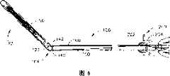
图6是示出了图1所示的端部执行器的关节运动的顶部剖面图;Figure 6 is a top cross-sectional view illustrating articulation of the end effector shown in Figure 1;
图7是示出了闭合管组件和支撑在手柄组件内的梭子布置的实施例的分解组装图,为了清楚省略了外壳组件内的其他部件;Figure 7 is an exploded assembly view showing an embodiment of the closure tube assembly and shuttle arrangement supported within the handle assembly, with other components within the housing assembly omitted for clarity;
图8是本发明各个实施例的外壳组件布置的剖面图;Figure 8 is a cross-sectional view of the housing assembly arrangement of various embodiments of the invention;
图8A是可与本发明各个实施例结合应用的一部分闭合扳机锁定系统的局部剖面图;Figure 8A is a partial cross-sectional view of a portion of a closure trigger locking system that may be used in conjunction with various embodiments of the present invention;
图8B是本发明另一手柄组件实施例的剖面图,其中压缩气体源在手柄组件外部;Figure 8B is a cross-sectional view of another handle assembly embodiment of the present invention, wherein the source of compressed gas is external to the handle assembly;
图8C是本发明另一手柄组件实施例的剖面图;Fig. 8C is a sectional view of another handle assembly embodiment of the present invention;
图9是图8手柄组件的另一剖面图;Fig. 9 is another sectional view of the handle assembly of Fig. 8;
图10是刀杆布置和击发驱动构件的侧视图,该击发驱动构件包含本发明各个实施例的两级气缸组件,气缸组件以剖面图示出;Figure 10 is a side view of a knife bar arrangement and firing drive member comprising a two-stage cylinder assembly of various embodiments of the present invention, shown in cross-section;
图11是图10所示的刀杆和两级气缸布置的另一侧视图,其中刀杆在伸出位置;Figure 11 is another side view of the knife bar and two-stage cylinder arrangement shown in Figure 10, with the knife bar in the extended position;
图12是本发明另一刀杆和击发驱动构件布置的侧视图,其中刀杆被回缩到以剖面图示出的气缸组件中;Figure 12 is a side view of another knife bar and firing drive member arrangement of the present invention, wherein the knife bar is retracted into the air cylinder assembly shown in cross-section;
图13是图12所示的刀杆和气缸布置的另一侧视图,其中刀杆在伸出位置;Figure 13 is another side view of the knife bar and cylinder arrangement shown in Figure 12, with the knife bar in the extended position;
图14是容纳图12和13中所示的气缸和刀杆布置的端部执行器和脊组件布置的俯视图;Figure 14 is a top view of the end effector and spine assembly arrangement housing the cylinder and knife bar arrangement shown in Figures 12 and 13;
图15是图14所示的端部执行器和脊组件布置的剖面侧视图,其中钉砧部分连接于其上并处于打开位置;15 is a cross-sectional side view of the end effector and spine assembly arrangement shown in FIG. 14 with the anvil portion attached thereto and in an open position;
图16是与图12-15所示的实施例结合使用的手柄组件的剖面图;Figure 16 is a cross-sectional view of a handle assembly for use with the embodiment shown in Figures 12-15;
图16A是与图12-15所示的实施例结合使用的手柄组件的另一剖面图,其中压缩气体源在手柄组件的外部;Figure 16A is another cross-sectional view of a handle assembly for use with the embodiment shown in Figures 12-15, wherein the source of compressed gas is external to the handle assembly;
图16B是本发明另一手柄组件实施例的剖面图;Figure 16B is a cross-sectional view of another handle assembly embodiment of the present invention;
图17是支撑本发明另一实施例的另一击发驱动构件的另一刀杆和脊组件布置的俯视图,所述另一击发驱动构件是波纹管组件的形式;17 is a top view of another knife bar and spine assembly arrangement supporting another firing drive member in the form of a bellows assembly in accordance with another embodiment of the present invention;
图18是图17所示的实施例的端部执行器和脊组件布置的剖面侧视图;Figure 18 is a cross-sectional side view of the end effector and spine assembly arrangement of the embodiment shown in Figure 17;
图19是图17和18所示的实施例的波纹管组件的局部剖面组装视图;Figure 19 is a partially cutaway assembled view of the bellows assembly of the embodiment shown in Figures 17 and 18;
图20是图19波纹管组件一部分的放大视图;Figure 20 is an enlarged view of a portion of the bellows assembly of Figure 19;
图21是与图17-20中所示的实施例结合使用的手柄组件实施例的剖面图;Figure 21 is a cross-sectional view of an embodiment of a handle assembly for use with the embodiment shown in Figures 17-20;
图21A是与图17-20中所示的实施例结合使用的另一手柄组件实施例的剖面图,其中压缩气体源在手柄组件的外部;Figure 21A is a cross-sectional view of another handle assembly embodiment for use with the embodiment shown in Figures 17-20, wherein the source of compressed gas is external to the handle assembly;
图21B是本发明另一手柄组件实施例的剖面图;Figure 21B is a cross-sectional view of another handle assembly embodiment of the present invention;
图22是根据本发明其他实施例的另一外科切割和紧固器械的透视图;Figure 22 is a perspective view of another surgical cutting and fastening instrument according to other embodiments of the present invention;
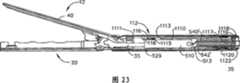
图23是图22所示的实施例的端部执行器和脊组件的剖面侧视图;Figure 23 is a cutaway side view of the end effector and spine assembly of the embodiment shown in Figure 22;
图24是在将远侧轴组件连接到近侧轴组件之前图22和23的实施例的快速脱离接头布置的剖面图;24 is a cross-sectional view of the quick disconnect joint arrangement of the embodiment of FIGS. 22 and 23 prior to connecting the distal shaft assembly to the proximal shaft assembly;
图25是图24中沿线25-25截取的近侧轴组件的剖面图;25 is a cross-sectional view of the proximal shaft assembly of FIG. 24 taken along line 25-25;
图26是连接近侧轴组件的远侧轴组件的局部透视图,其中为了清楚省略了一部分远侧轴组件;26 is a partial perspective view of the distal shaft assembly coupled to the proximal shaft assembly, with a portion of the distal shaft assembly omitted for clarity;
图27是图24-26的实施例的接头组件的剖面侧视图,其中远侧轴组件连接到近侧轴组件上;27 is a cross-sectional side view of the joint assembly of the embodiment of FIGS. 24-26 with the distal shaft assembly connected to the proximal shaft assembly;
图28是在连接到近侧轴组件之前一部分远侧轴组件的透视图;Figure 28 is a perspective view of a portion of the distal shaft assembly prior to connection to the proximal shaft assembly;
图29是可用于图12-16A所示的实施例的另一快速脱离接头布置的局部剖面图;Figure 29 is a partial cross-sectional view of another quick disconnect arrangement that may be used with the embodiment shown in Figures 12-16A;
图30是图29中沿线30-30截取的近侧轴组件的剖面图;30 is a cross-sectional view of the proximal shaft assembly of FIG. 29 taken along line 30-30;
图31是与图22-30所示的实施例结合使用的一部分近侧轴组件的透视图;Figure 31 is a perspective view of a portion of a proximal shaft assembly for use with the embodiment shown in Figures 22-30;
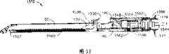
图32是本发明另一外科切割和紧固器械的透视图,其应用了本发明各个实施例的气动致动关节运动接头;Figure 32 is a perspective view of another surgical cutting and fastening instrument of the present invention employing pneumatically actuated articulation joints of various embodiments of the present invention;
图33是将远侧脊段连接到图32所示的实施例的近侧脊段上的一部分关节运动接头的局部透视图;Figure 33 is a partial perspective view of a portion of the articulation joint connecting the distal spine segment to the proximal spine segment of the embodiment shown in Figure 32;
图34是图33的关节运动接头布置的另一透视图,其中从其上去除封盖,且示出了相对于近侧脊段关节运动的远侧脊段;34 is another perspective view of the articulation joint arrangement of FIG. 33 with the cover removed therefrom and showing the distal spine segment articulated relative to the proximal spine segment;
图35是图33和34的关节运动接头布置的分解组装视图;Figure 35 is an exploded assembly view of the articulation joint arrangement of Figures 33 and 34;
图36是图33-35的接头组件的剖面侧视图;Figure 36 is a cutaway side view of the connector assembly of Figures 33-35;
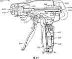
图37是本发明开关组件的实施例的透视图;Figure 37 is a perspective view of an embodiment of a switch assembly of the present invention;
图38是图37开关组件的侧视图;Figure 38 is a side view of the switch assembly of Figure 37;
图39是图37中沿线39-39截取的图37和38的开关组件的剖面图;Figure 39 is a cross-sectional view of the switch assembly of Figures 37 and 38 taken along line 39-39 of Figure 37;
图40是图38中沿线40-40截取的在脱开位置上的开关组件的剖面图;Figure 40 is a cross-sectional view of the switch assembly in the disengaged position taken along line 40-40 of Figure 38;
图41是处于致动位置上的图37-40的开关组件的另一剖面图;41 is another cross-sectional view of the switch assembly of FIGS. 37-40 in an actuated position;
图42是图41中沿线42-42截取的图41的开关组件的剖面图;42 is a cross-sectional view of the switch assembly of FIG. 41 taken along line 42-42 of FIG. 41;
图43是图37-42的开关组件的仰视图;Figure 43 is a bottom view of the switch assembly of Figures 37-42;
图44是在其内具有图37-43的开关组件并容纳压缩气体源的手柄组件的剖面图;44 is a cross-sectional view of the handle assembly having the switch assembly of FIGS. 37-43 therein and housing a source of compressed gas;
图45是在其内具有图37-43的开关组件的手柄组件的剖面图,其中压缩气体源在手柄组件的外部;Fig. 45 is a cross-sectional view of a handle assembly having the switch assembly of Figs. 37-43 therein, wherein the source of compressed gas is external to the handle assembly;
图46是本发明另一外科缝合和切割器械的透视图,其应用了图33-36中所示的关节运动接头的实施例以及图23-31中所示的快速脱离接头的实施例;Figure 46 is a perspective view of another surgical stapling and cutting instrument of the present invention employing the embodiment of the articulation joint shown in Figures 33-36 and the embodiment of the quick release joint shown in Figures 23-31;
图47是在将远侧轴组件连接到近侧轴组件之前图46的实施例的快速脱离接头布置的剖面图;47 is a cross-sectional view of the quick disconnect joint arrangement of the embodiment of FIG. 46 prior to connecting the distal shaft assembly to the proximal shaft assembly;
图48是图47中沿线48-48截取的图47的实施例的接头组件的剖面图;48 is a cross-sectional view of the joint assembly of the embodiment of FIG. 47 taken along line 48-48 in FIG. 47;
图49是本发明另一外科切割和紧固器械的实施例的透视图;Figure 49 is a perspective view of another embodiment of a surgical cutting and fastening instrument of the present invention;
图50是与图49中所示的实施例结合使用的端部执行器布置的分解组装视图;Figure 50 is an exploded assembly view of an end effector arrangement for use with the embodiment shown in Figure 49;
图51是与图49中所示的实施例结合使用的端部执行器布置、脊组件和闭合管组件的分解组装视图;Figure 51 is an exploded assembly view of an end effector arrangement, spine assembly and closure tube assembly for use with the embodiment shown in Figure 49;
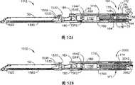
图52是图51的端部执行器、脊组件和闭合管组件的剖面侧视图,其中为了清楚省略了钉砧部分;52 is a cross-sectional side view of the end effector, spine assembly, and closure tube assembly of FIG. 51 with the anvil portion omitted for clarity;
图52A是本发明另一非限制性实施例的端部执行器、脊组件和闭合管组件的剖面侧视图,其中从手柄组件的远侧支撑气动马达;52A is a cross-sectional side view of an end effector, spine assembly, and closure tube assembly of another non-limiting embodiment of the present invention, with the air motor supported from the distal side of the handle assembly;
图52B是本发明另一非限制性实施例的端部执行器、脊组件和闭合管组件的剖面侧视图,其中从手柄组件的远侧支撑气动马达;52B is a cross-sectional side view of an end effector, spine assembly, and closure tube assembly of another non-limiting embodiment of the present invention, with the air motor supported from the distal side of the handle assembly;
图53是与图49的实施例结合使用的手柄组件的剖面图;Figure 53 is a cross-sectional view of a handle assembly for use with the embodiment of Figure 49;
图53A是可与图49的实施例结合使用的另一手柄组件的剖面图,其中压缩气体源在手柄组件的外部;Figure 53A is a cross-sectional view of another handle assembly that may be used in conjunction with the embodiment of Figure 49, wherein the source of compressed gas is external to the handle assembly;
图54是图53手柄组件的另一剖面图;Figure 54 is another sectional view of the handle assembly of Figure 53;
图55是本发明各个实施例的相对位置击发扳机布置的侧视图;Figure 55 is a side view of relative positional firing trigger arrangements of various embodiments of the present invention;
图56是可与本发明各个实施例结合使用的本发明控制系统实施例的示意图;Figure 56 is a schematic diagram of an embodiment of the control system of the present invention that may be used in conjunction with various embodiments of the present invention;
图57是可从本发明各个手柄组件实施例的原始连接部分上分离的可分离握持部分的剖面图;Figure 57 is a cross-sectional view of a detachable grip portion detachable from the original connection portion of various handle assembly embodiments of the present invention;
图58是显示了与本发明各个实施例的手柄组件原始连接部分相连的可分离握持部分的局部剖面图;FIG. 58 is a partial cross-sectional view showing a detachable grip portion connected to an original connection portion of a handle assembly according to various embodiments of the present invention;
图59是图58的可分离握持部分和原始连接部分的局部剖面图,并且为了清楚省略了头部和相关的气缸部件;Figure 59 is a partial cross-sectional view of the detachable grip portion and original connection portion of Figure 58, with the head and associated cylinder components omitted for clarity;
图60是图59中沿线60-60截取的图58和59的可分离握持部分和原始连接部分的剖面图;Figure 60 is a cross-sectional view of the detachable grip portion and original attachment portion of Figures 58 and 59 taken along line 60-60 of Figure 59;
图61是图59中沿线61-61截取的图58和59的可分离握持部分和原始连接部分的剖面图;Figure 61 is a cross-sectional view of the detachable grip portion and original attachment portion of Figures 58 and 59 taken along line 61-61 of Figure 59;
图62是图59中沿线62-62截取的图58-61的可分离握持部分和原始连接部分的剖面图;Figure 62 is a cross-sectional view of the detachable grip portion and original attachment portion of Figures 58-61 taken along line 62-62 of Figure 59;
图63是图59中沿线63-63截取的图58-61的可分离握持部分和原始连接部分的另一局部剖面图;Figure 63 is another partial cross-sectional view of the detachable grip portion and original attachment portion of Figures 58-61 taken along line 63-63 of Figure 59;
图64是在初始位置上的本发明锁止系统实施例的图解视图;Figure 64 is a diagrammatic view of an embodiment of the locking system of the present invention in an initial position;
图65是图64的锁止系统的另一图解视图,示出了当握持构件初始地连接到手柄组件的原始连接部分上时它的动作;Figure 65 is another diagrammatic view of the locking system of Figure 64, showing the action of the gripping member when it is initially connected to the original connection portion of the handle assembly;
图66时在握持构件从手柄组件的原始连接部分上再次分离之前,图64和65的锁止系统的另一图解视图;Figure 66 is another diagrammatic view of the locking system of Figures 64 and 65 before the gripping member is separated again from the original connection portion of the handle assembly;
图67是图64-66的锁止系统的另一图解视图,示出了当握持部分已经连接到原始连接部分上时系统部件的位置;Figure 67 is another diagrammatic view of the locking system of Figures 64-66, showing the position of the system components when the grip portion has been attached to the original attachment portion;
图68是图64-66的锁止系统的另一图解视图,示出了在握持部分再次连接到原始连接部分期间系统部件的位置;Figure 68 is another diagrammatic view of the locking system of Figures 64-66, showing the position of the system components during reconnection of the grip portion to the original connection portion;
图69是示出了握持构件已经再次或最后连接到原始连接部分之后,锁止系统的另一图解视图;Figure 69 is another diagrammatic view showing the locking system after the gripping member has been re- or finally connected to the original connection part;
图70是本发明另一外科切割和紧固器械实施例的透视图;Figure 70 is a perspective view of another surgical cutting and fastening instrument embodiment of the present invention;
图71是可与图70所示的器械结合使用的手柄组件实施例的剖面图;Figure 71 is a cross-sectional view of an embodiment of a handle assembly usable with the instrument shown in Figure 70;
图72是本发明各个实施例的梭子和回缩棒组件的分解组装视图;Figure 72 is an exploded assembly view of the shuttle and retraction rod assembly of various embodiments of the present invention;
图72A是本发明另一实施例的梭子和回缩棒组件的分解组装视图;Figure 72A is an exploded assembly view of a shuttle and retraction rod assembly according to another embodiment of the present invention;
图73是图72所示的部件的组装视图,其气缸组件在完全伸出位置上;Figure 73 is an assembled view of the components shown in Figure 72 with the cylinder assembly in the fully extended position;
图74是本发明的梭子组件的实施例的后视图;Figure 74 is a rear view of an embodiment of the shuttle assembly of the present invention;
图75是图74的梭子组件的另一后视图,其中回缩棒和推杆伸入推杆开口,并且推杆连接到连接器构件上;75 is another rear view of the shuttle assembly of FIG. 74 with the retraction rod and push rod extending into the push rod opening and the push rod connected to the connector member;
图76是梭子组件左侧部分的后透视图;Figure 76 is a rear perspective view of the left side portion of the shuttle assembly;
图77是梭子组件左侧部分的另一后透视图;Figure 77 is another rear perspective view of the left side portion of the shuttle assembly;
图78是用于图70-77中所示的实施例的控制系统布置的示意性示图;Figure 78 is a schematic illustration of a control system arrangement for the embodiment shown in Figures 70-77;
图79是图70-78中所示的实施例的手柄组件布置的剖面图,其中气缸组件在伸出位置;Figure 79 is a cross-sectional view of the handle assembly arrangement of the embodiment shown in Figures 70-78 with the cylinder assembly in the extended position;
图80是图70-79中所示的实施例的手柄组件布置的另一顶部剖面图,其中气缸组件在回缩位置;Figure 80 is another top sectional view of the handle assembly arrangement of the embodiment shown in Figures 70-79 with the cylinder assembly in the retracted position;
图81是图70-80中所示的实施例的手柄组件的剖面图;Figure 81 is a cross-sectional view of the handle assembly of the embodiment shown in Figures 70-80;
图81A是可用于图70-80中所示的实施例的手柄组件实施例的剖面图,其中压缩气体源在手柄组件的外部;Figure 81A is a cross-sectional view of an embodiment of a handle assembly that may be used with the embodiments shown in Figures 70-80, wherein the source of compressed gas is external to the handle assembly;
图82是图81的手柄组件另一剖面图,其中气缸组件被伸出;Figure 82 is another cross-sectional view of the handle assembly of Figure 81 with the cylinder assembly extended;
图83是图81的手柄组件另一剖面图,其中气缸组件被回缩;以及Figure 83 is another cross-sectional view of the handle assembly of Figure 81 with the cylinder assembly retracted; and
图83A是图72B中所示的实施例手柄组件的剖面图,其中气缸组件被回缩并且击发棒处于其最近侧位置。83A is a cross-sectional view of the embodiment handle assembly shown in FIG. 72B with the cylinder assembly retracted and the firing rod in its proximal-most position.
具体实施方式Detailed ways
回到附图,其中相同的附图标记在所有附图中表示相同的部件,图1示出了能够实施本发明若干独特优势的外科缝合和切割器械10。图1中示出的实施例包括手柄组件300、细长轴组件100和连接到细长轴组件100的端部执行器12。本发明各个实施例可包括一种端部执行器,其如在2006年1月10提交的、题为“SURGICALINSTRUMENT HAVING AN ARTICULATING END EFFECTOR”美国专利申请No.11/329,020中所公开的端部执行器一样能枢转地连接到细长轴组件100并枢转地由弯曲的缆线或带进行驱动,上述申请通过引用并入本文。然而,随着对具体实施方式的继续描述,本领域的普通技术人员应当理解本发明各个实施例能成功地与端部执行器布置结合进行实施,所述端部执行器可采用不同的枢转机构和控制器,并且本发明各个实施例可成功地与非关节运动式端部执行器布置结合使用,如下面将详细解释的一样。Returning to the drawings, wherein like reference numerals refer to like parts throughout, FIG. 1 illustrates a surgical stapling and cutting
如图1中所示,器械10的手柄组件300可包括闭合扳机302和击发扳机310。应当理解,针对不同手术任务具有端部执行器的器械可具有不同数量和类型的扳机或其他用于端部执行器操作的合适控制器。所示的端部执行器12通过优选为细长的轴组件100与手柄组件300分离。临床医生可通过利用致动控制器200使端部执行器12相对于轴组件100作关节运动。As shown in FIG. 1 , handle
应该理解,在此参照附图给出的空间术语诸如竖直、水平、右、左等假设外科器械10的纵向轴线与细长轴组件100的中心轴线同轴,其中扳机302,310以锐角从手柄组件300的底部向下延伸。然而,在实际应用中,可将外科器械10以多个角度定向,这样,相对于外科器械10本身使用这些空间术语。此外,“近侧”用于表示将端部执行器12放置在临床医生远侧或远处的在手柄组件300后方的他或她的视角。It should be understood that spatial terms such as vertical, horizontal, right, left, etc. given herein with reference to the figures assume that the longitudinal axis of the
如此处所用的,术语“压缩气体”指适于用在无菌环境下所用的气动系统中的任何气体。这种介质的非限制示例包括压缩空气、二氧化碳(CO2)、氮、氧、氩、氦、氢化钠、丙烷、异丁烷、丁烷、氯氟甲烷、二甲醚、甲基乙醚、一氧化氮、氢氟烷推进剂(HFA),例如HFA134a(1,1,1,2,-四氟乙烷)或HFA227(1,1,1,2,3,3,3-七氟丙烷)。As used herein, the term "compressed gas" refers to any gas suitable for use in a pneumatic system used in a sterile environment. Non-limiting examples of such media include compressed air, carbon dioxide (CO2), nitrogen, oxygen, argon, helium, sodium hydride, propane, isobutane, butane, chlorofluoromethane, dimethyl ether, methyl ether, monoxide, Nitrogen, hydrofluoroalkane propellants (HFA), such as HFA134a (1,1,1,2,-tetrafluoroethane) or HFA227 (1,1,1,2,3,3,3-heptafluoropropane).
如此处所用的,术语“流体连接”是指元件与适合的管路或者其他部件一起连接以允许压缩气体在其间通过。如此处所用的,如用在“供应管路”或“返回管路”中的术语“管路”指由刚性或柔性导管、管道、管材等形成的适当的通路,用于将压缩气体从一个部件传送到另一部件。As used herein, the term "fluidically connected" means that elements are connected together with suitable piping or other components to allow compressed gas to pass therebetween. As used herein, the term "line" as used in "supply line" or "return line" means a suitable passageway formed by rigid or flexible conduit, pipe, tubing, etc. Part transfers to another part.
如此处所用的,术语“气动信号”或“气动驱动信号”指从压缩气体源到与压缩气体源流体连接的一个或多个部件的气体流或者指彼此流体连接的部件之间的气体流。As used herein, the term "pneumatic signal" or "pneumatic drive signal" refers to the flow of gas from a source of compressed gas to one or more components fluidly connected to the source of compressed gas or between components fluidly connected to each other.
如此处所用的,语句“基本上垂直于纵向轴线”指几乎与纵向轴线的方向垂直,其中“纵向轴线”是轴的轴线。然而,应当理解,稍微偏离垂直于纵向轴线的方向也认为基本上垂直于纵向轴线。As used herein, the phrase "substantially perpendicular to the longitudinal axis" means nearly perpendicular to the direction of the longitudinal axis, where "longitudinal axis" is the axis of the shaft. However, it should be understood that directions that deviate slightly from perpendicular to the longitudinal axis are also considered substantially perpendicular to the longitudinal axis.
图2示出了可用于本发明各个实施例中的一种气动操作工具组件或端部执行器的分解组装视图。将图1-4中所示的气动操作工具组件12构造成用作气动内镜切割器。然而,随着对具体实施方式的描述,应当理解,同样可构想将本发明实施例的各个独特和新颖的驱动布置用于驱动被构造成执行其他手术任务的其他端部执行器,从而需要对附图中所示物体进行部件的拆卸、修改或增加。同样,应当理解,可以为了特定的手术应用而定制图1-4中所示的端部执行器12。Figure 2 shows an exploded assembly view of a pneumatically operated tool assembly or end effector that may be used in various embodiments of the present invention. The pneumatically operated
图2中示出了一种可用于本发明各个实施例的端部执行器。如图中所示,端部执行器12应用电子束(E-beam)击发机构(“刀组件”)30,其除了切割组织并击发位于钉仓中的缝钉,还有利地相对于钉仓控制端部执行器12的钉砧部分间隔。在授予Shelton,IV等人的题为“集成电子束击发机构的外科缝合器械”的美国专利No.6,978,921中描述了电子束击发机构的各个方面,其相关部分通过引用并入本文。然而,根据对具体实施方式的描述,本领域的普通技术人员应当理解在不脱离本发明精神和范围的情况下可有利地应用其他刀和击发机构构型。An end effector that may be used with various embodiments of the invention is shown in FIG. 2 . As shown,
如此处所用的,术语“击发机构”是指从未致动位置移动的气动工具和/或端部执行器的一部分或多个部分,其中击发机构基本上停靠在致动位置或称末端位置,其中所述一部分或多个部分移动或重新定位到最终位置,其中这种移动导致工具响应至少一次击发动作的施加而完成一个或多个动作。该击发机构可例如包括:(i)完全由气动工具支撑并与手术设备中的部件配接的部件;(ii)定位在气动工具和手术设备中的部件的组合;或(iii)由手术设备支撑并可进出气动工具的部件。如此处所用的,术语“击发冲程”是指击发机构从未致动位置到致动位置的实际移动。术语“回缩冲程”是指击发机构从致动位置到未致动位置的返回移动。As used herein, the term "firing mechanism" refers to a part or parts of a pneumatic tool and/or end effector that is moved from an unactuated position, wherein the firing mechanism is substantially rested in an actuated or end position, wherein the portion or portions are moved or repositioned to a final position, wherein such movement causes the tool to perform one or more actions in response to application of at least one firing action. The firing mechanism may, for example, include: (i) a component fully supported by the pneumatic tool and mated with a component in the surgical device; (ii) a combination of components positioned in the pneumatic tool and surgical device; Components that support and provide access to air tools. As used herein, the term "firing stroke" refers to the actual movement of the firing mechanism from an unactuated position to an actuated position. The term "retraction stroke" refers to the return movement of the firing mechanism from the actuated position to the unactuated position.
如图2中所示,端部执行器12包括远侧构件,具在各个非限制性实施例中包含具有连接于其上的可平移的钉砧40的细长通道20。该细长通道20被构造成接收和支撑钉仓50以响应刀组件30驱动缝钉70接触钉砧40。应当理解,虽然在此有利地描述了易于替换的钉仓,但是与本发明多个方面相符的钉仓可永久地固定或一体地形成于细长通道20中。As shown in FIG. 2 ,
在各个实施例中,击发机构或刀组件30包括在击发过程中控制端部执行器12间隔的竖直间隔销。具体地,上部销32行进进入到钉砧40和细长通道20之间的枢轴附近的钉砧袋42中。参见图4。当随钉砧40闭合击发之后,上部销32向远侧前进到穿过钉砧40向远侧延伸的纵向钉砧狭槽44中。通过上部销32施加的向下的力来克服在钉砧40中的任何镜像向上移动。In various embodiments, the firing mechanism or
刀组件30还包括向上接合在细长通道20中形成的通道狭槽23(图2)的刀杆帽34,从而与上部销32协作,以在钉砧40和细长通道20之间夹紧的组织超出的情况下,将钉砧40和细长通道20稍微地拉得更靠近些。在各个实施例中,刀组件30可有利地包括中部销36,其穿过在钉仓50的下表面和细长通道20的上表面所形成的击发驱动狭槽(未显示),从而如下面所述的来驱动其中的缝钉70。中部销36通过在细长通道20上进行滑动有利地抵抗任何将端部执行器12压紧关闭到其远端的趋势。然而,通过使用其他刀组件布置可实现本发明各个实施例的独特和新颖方面。The
回到图2,在刀组件30上的上部销32和中部销36之间的位于远侧的切割刃38横过钉仓50中位于近侧的竖直狭槽54,来切断夹紧的组织。刀组件30相对于细长通道20和钉砧40的确定定位确保执行有效的切割。在各个实施例中,钉砧40的下表面在其中可设有多个缝钉成形袋(未显示),当在细长通道内接收钉仓50时,这些缝钉成形袋排列成对应于钉仓50的上表面56中的多个缝钉孔58。在各个实施例中,可将钉仓50扣合匹配到细长通道20中。具体地,钉仓50的延伸部分60,62分别摩擦地且可释放地接合细长通道20的凹槽24,26。2, the distally located cutting
还如图2中所示,钉仓50包含仓体51、楔形滑道64、缝钉驱动器66、缝钉70和仓盘68。当装配时,仓盘68将楔形滑道64、缝钉驱动器66和缝钉70保持在仓体51中。通过细长轴组件100将细长通道20连接到手柄组件300,该细长轴组件100包括远侧脊或框架段110以及近侧脊或框架段130。细长通道20在近侧设置有连接腔22,每一个连接腔22接收在近侧脊段110的近端上所形成的相应通道锚定构件114。该细长通道20还具有枢转地接收钉砧40上的相应钉砧枢轴43的钉砧凸轮槽28。闭合的衬套组件170接收于脊组件102之上,并包括远侧闭合管段180和近侧闭合管段190。如下面将要描述的,闭合衬套组件170相对于脊组件102的轴向移动引起钉砧40相对于细长通道20枢转。As also shown in FIG. 2 ,
如在图2中所示,将锁定弹簧112安装在远侧脊段110上用作刀组件30的锁止件。在远侧脊段110上形成远侧和近侧方孔111,113以限定其间的夹杆115,夹杆115接收锁定弹簧112的顶臂116,如下面将进一步详细讨论的,锁定弹簧112的下部远侧延伸臂118在气缸组件501的远侧上施加向下的力,支撑从刀组件30突出的活塞杆部分5。应当理解,各个实施例可包含其他类型的锁止件或根本没有锁止件。As shown in FIG. 2 , a
在图1-6所示的实施例中,通过能够弯曲以将端部执行器12围绕枢轴104拉动的缆线或带的集合可使端部执行器12相对于近侧闭合管段190(和手柄组件300)进行关节运动。本领域的普通技术人员将会理解,这种布置仅代表能与这些类型的设备结合使用的多种关节运动布置的其中之一。在该实施例中,远侧脊段110的近端在其上具有隆凸。近侧脊段130的远端设有带贯穿其中的孔136的柄脚134。近侧脊段130相对于远侧脊段110进行定位,使得孔136与隆凸122中的孔124共轴对齐,以便使枢轴销138能从中穿过。见图4,当组装时,这种布置允许端部执行器12相对于近侧脊段130围绕枢转轴线A-A进行枢转。In the embodiment shown in FIGS. 1-6 , the
如上所述,该实施例应用带来使端部执行器12作关节运动。具体地,带150,160可如图2和3中所示朝着关节运动枢轴104向远侧延伸。带150可沿其左侧穿过近侧闭合管段190延伸,其中它途经带构件160并越过近侧闭合管段190的右侧。此处,例如,带150可在连接点123处机械地连接到隆凸122。同样,带160可沿其右侧穿过近侧闭合管段190延伸,其中它途径带构件150并越过近侧闭合管段190的左侧。此处,带160可在连接点125处机械地连接到隆凸122。As noted above, this embodiment utilizes belts to articulate the
图3是在具有虚线所示的闭合管组件100的端部执行器和脊组件102的俯视图。图4是器械10的相同部分的局部剖面侧视图。如图4中所示,根据一非限制性实施例,所示的带150和160显示为彼此偏移以防止运动中的干扰。例如,将带150显示为比带160更低的位置。在另一非限制性实施例中,可颠倒带150和160的竖直位置。同样如图2和3中所示,带构件150围绕近侧框架段130的柄脚部分134中的销140延伸。同样,带构件160围绕近侧框架段130的柄脚部分134中的销142延伸。同样可参见图2。3 is a top view of the end effector and
带部分150和160可从隆凸122沿近侧闭合管段190延伸到关节运动控制器200,图5中所示。关节运动控制器200可包括关节运动滑块202、框架204和封罩206。带部分150,160可借助于槽208或其他孔穿过关节运动滑块202,但是应当理解带部分150,160可通过任何合适的手段连接到滑块202上。关节运动滑块202可以是一片,如图5所示,或在一非限制性实施例中的两片,其中两片之间的界面限定了槽208。在一个非限制性实施例中,关节运动滑块可例如包括多个槽,每个槽对应其中一个带部分150,160。封罩206可覆盖控制器200的各个部件以防止碎屑进入。
在各个实施例中,带150,160可在从槽208近侧定位的连接点210,212处锚定到框架204上。图5的非限制性实施例显示带部分150,160从连接点210,212到在近侧闭合管段190的纵向轴线附近定位的槽208预弯曲。应当理解,可将带150,160锚定到从槽208近侧定位的器械10上的任何地方,包括手柄组件300。In various embodiments, straps 150 , 160 may be anchored to frame 204 at attachment points 210 , 212 located proximally from slot 208 . The non-limiting example of FIG. 5 shows that the
在使用中,图2的实施例可具有如图所示的非关节运动位置。所示的关节运动控制器200和带150,160位于轴组件100的纵向轴线的大致中间位置上。因此,端部执行器12在中间或非关节运动位置。在图6中,显示了关节运动控制器200,其中关节运动滑块202推过关节运动框架到轴组件100的右侧。因此,带150,160朝轴组件100的右侧弯曲。由此可知,带150向右侧的弯曲在隆凸122上施加从隆凸122的枢轴点偏移的横向力。该偏移力促使隆凸122围绕关节运动枢轴104旋转,又如图所示促使端部执行器12向右枢转。应当理解,将关节运动滑块202推向轴组件100的左侧可在带150,160上施加侧向力,使带150,160都朝轴组件100的左侧弯曲。接着带160的弯曲在隆凸122上施加侧向力,其如上所述一样从隆凸122的枢轴点偏移。这又促使隆凸122围绕关节运动枢轴旋转,促使端部执行器12向左枢转。In use, the embodiment of Figure 2 may have a non-articulating position as shown.
在各个实施例中,轴组件100包含接收在脊组件120上的闭合管组件170。参见图2。闭合管组件170包含远侧闭合管段180和近侧闭合管段190。远侧闭合管段180和近侧闭合管段190可由聚合物或其他合适的材料制造。近侧闭合管段190是中空的并具有贯穿其中的轴向通道191,其大小适于将一部分脊组件102接收其中。In various embodiments, the
在图2和4所示的实施例中,应用双枢轴闭合接头172。应当理解,本发明并非限于双枢轴闭合接头设计并可包括任何合适的闭合管或衬套,或者根本没有闭合管或衬套。特别参考图4,远侧闭合管段180具有上部和下部近侧凸出柄脚182,184。远侧闭合管段180还包括马蹄形孔185和翼片186,用于接合钉砧40上钉砧打开/关闭翼片46,以便如下面进一步详细讨论地促使钉砧40在打开和闭合位置之间枢转。参见图2。In the embodiment shown in Figures 2 and 4, a double pivot closure joint 172 is employed. It should be understood that the present invention is not limited to dual pivot closure joint designs and may include any suitable closure tube or bushing, or no closure tube or bushing at all. With particular reference to FIG. 4 , the distal
近侧闭合管段190类似地设有向远侧延伸的上部柄脚192和向远侧延伸的下部柄脚194。上部双枢轴链174包括向上突出的远侧和近侧枢轴销175,176,它们分别接合上部近侧的突出柄脚182中的上部远侧销孔183和上部远侧突出柄脚192中的上部近侧销孔193。接头布置还包括下部双枢轴连接件177,其使远侧和近侧枢轴销178,179(图2中未显示,但在图4中可见)向下突出,远侧和近侧枢轴销178,179分别接合下部近侧突出柄脚184中的下部远侧销孔187和下部侧突出柄脚194中的下部近侧销孔195。The proximal
在使用中,闭合管组件170例如响应于闭合扳机310的致动向远侧平移到闭合的钉砧40。通过将闭合管组件170向远侧平移到脊组件102上来闭合钉砧40,促使马蹄形孔185的背部撞击钉砧40上的打开/闭合翼片46,并促使它枢转到闭合位置。为了打开钉砧40,在脊组件102上的近侧方向上轴向移动闭合管组件170,促使翼片186接触并推动打开/闭合翼片46,以将钉砧40枢转到打开的位置。In use, the
图7示出了本发明各个实施例的非限制性手柄组件300的分解组装视图。在图7所示的实施例中,手柄组件具有“手枪式握把”结构并由右手壳构件320和左手壳构件330构成,右手壳构件320和左手壳构件330由聚合物或其他合适的材料模制或以其他方式制造并设计成匹配在一起。这种壳构件320和330可通过扣合部分、模制的栓和座或在内部形成的其他方式和/或通过粘合剂、螺钉、螺栓、夹具等连接在一起。右手壳构件320的上部322与左手壳构件330对应的上部323匹配以形成表示为340的主外壳部分。类似地,右手壳构件320的下握持部324与左手壳构件330对应的下握持部324匹配以形成表示为342的握持部。在图7所示的实施例中,整个握持部342与主外壳部分340形成一体。这种布置特别适于压缩气体源永久安装到握持部342中的应用。这种布置还适合用于这样的压缩气体源,它在手柄组件300的外部并通过外壳组件上的一个端口或多个端口插入到容纳在其中的控制部件中。在另一实施例中,如下面进一步详细描述的,握持部342可从主外壳部分340上拆除。根据对具体实施方式的描述应当理解,这种布置提供了众多的好处和优势。然而,本领域的普通技术人员应当理解能提供具有不同形状和大小的手柄组件300。FIG. 7 shows an exploded assembly view of a
为了清楚起见,图7仅示出了用于控制闭合管组件170轴向移动的部件,其最终控制钉砧40的打开和关闭。如图中所示,通过连杆组件430连接于闭合扳机302的闭合梭400支撑在主外壳部分340中。闭合梭400同样可制造成两片402,404,它们由聚合物或其他合适的材料模制或以其他方式制造并设计为互相匹配。例如,在图7示出的实施例中,右手部分402设有紧固柱403,其被设计用来接收到左手部分404中对应的座内(未显示)。右手部分和左手部分402,404可通过扣合构件和/或粘合剂和/或螺栓、螺钉、夹具等以其他方式进行保持。如图中可见,在近侧闭合管段190的近端设有保持沟槽196。闭合梭400的右手部分402具有右保持凸缘段405,其适于与闭合梭400左手部404上的左保持凸缘段(未显示)协作来形成延伸进入近侧闭合管段190的保持沟槽196中的保持凸缘组件。For clarity, FIG. 7 shows only the components used to control the axial movement of
如图7中所示,右脊组件保持栓326从右手壳构件320向内突出。这种栓326伸入闭合梭400右手部402中的狭槽或窗406中。类似的闭合梭保持栓(未显示)从左手壳构件330向内突出,并被接收于闭合梭400左手部402中所设的另一窗或槽408中。保持栓用作将近侧脊段130的近端133(图7未显示)不可移动地固定在手柄组件300上,同时允许闭合梭400相对于它轴向移动。通过例如螺栓、螺钉、粘合剂、扣合部件等可将保持栓机械地连接到近侧脊段130的近端。另外,闭合梭400设有侧向延伸的导轨410,411。导轨410被构造成可滑动地接收于右手壳构件320中的导轨导向件328中,并且导轨411被构造成可滑动地接收于左手壳构件330中的导轨导向件(未显示)中。As shown in FIG. 7 , the right spine assembly retention peg 326 projects inwardly from the
通过朝手柄组件300的握持部342移动闭合扳机302来产生闭合梭400和闭合管组件170在远侧方向上(箭头“C”)的轴向移动,并且通过将闭合扳机302远离握持部342来产生闭合梭400在近侧方向上(箭头“D”)的轴向移动。在各个实施例中,闭合梭400设有方便连接闭合连杆组件430的连接器翼片412。参见图8和9。闭合连杆组件430包括通过销414枢转地销接到连接器翼片412上的轭部432。闭合连杆组件430还具有闭合臂434,如图7中所示闭合臂434通过闭合销436枢转地销接到在闭合扳机302上形成的轭组件304上。通过在右手壳部320和左手壳部330之间延伸的枢轴销306,将闭合扳机302枢转地安装在手柄组件300内。Axial movement of the
当临床医生想要闭合钉砧40以夹紧端部执行器12中的组织时,临床医生朝握持部342拉动闭合扳机302。当临床医生朝握持部342拉动闭合扳机302时,闭合连杆组件430在远侧“C”方向上移动闭合梭400,直到闭合连杆组件430移入图8所示的锁定位置内。当在这一位置中时,闭合连杆组件430倾向于将闭合梭400保持在该锁定位置上。当闭合梭400移到锁定位置时,闭合管组件170在脊组件102上向远侧移动,促使远侧闭合管段180内的马蹄形孔185的近端接触钉砧40上的闭合/打开翼片46,从而将钉砧40枢转到闭合(夹紧)位置。When the clinician wishes to close
在各个实施例中,为了进一步将闭合梭400保持在闭合位置上,闭合扳机302可设有可释放的锁定机构301,其适于接合握持部342和可释放地将闭合扳机302保持在锁定位置上。其他锁定装置也可用于可释放地将闭合梭400保持在锁定位置上。在图8,8A,8B和9所示的实施例中,闭合扳机302包括柔性纵向臂303,其包括从其延伸的侧销305。例如,臂303和销305可由模制塑料制成。手柄组件300的手枪式握把部342包括在其中设置有侧向延伸的楔块352的开口350。当回缩闭合扳机302时,销305接合楔块352,并且楔块352的下表面迫使销305向下(即,臂303顺时针旋转)。当销305完全通过下表面354时,去除臂303上的顺时针的力,并且销305逆时针旋转,使得销305停靠在楔块352后的凹口356中,从而锁定闭合扳机302。通过从楔块352延伸的柔性挡块358进一步将销305保持在锁定位置中。In various embodiments, to further maintain the
为了解锁闭合扳机302,操作者可进一步挤压闭合扳机302,促使销305接合开口350的倾斜后壁359,迫使销305向上经过柔性挡块358。接着销305可自由地穿出开口360中的上通道,使得闭合扳机302不再锁定到手枪式握把部342上。在授予Shelton,IV等人的、于2006年1月31日提交的题为“具有可拆卸电池的外科器械”的美国专利申请No.11/344,020中公开了这种布置的其他细节,该申请的相关部分通过引用并入本文。还可应用其他可释放锁定布置。To unlock the
在本发明各个实施例中,刀组件30可具有从其上突出或以其他方式与其连接的基本上为刚性的活塞杆部35,其是驱动构件500的一部分,可操作地由远侧脊段110支撑并被构造成给刀组件30施加至少两个致动动作(例如击发动作和回缩动作)。在图3、4、10和11所示的实施例中,驱动构件500包含两级气动致动气缸组件501。刀组件30可由一个整体部件构成或可被设置成由多个部件构成以使器械10的组件更容易推动。例如,如图10和11所示,刀杆组件30包含远侧部分31,其含有上部销32、帽34、中部销36和刀38。远侧部分31可设有孔33,其大小适于接收在活塞杆部35的远侧末端上设置的突起37。突起37可摩擦地接收于孔33中和/或通过粘合、焊接等保持在其中。In various embodiments of the invention, the
气缸组件501包含第一气缸外壳510,其具有第一闭合近端512和通入第一气缸外壳510中的第一轴向通道516内的第一打开远端514。气缸组件501还包含第一气缸外壳520,其具有第二近端522和通入第二轴向通道526的第二打开远端524。第二闭合近端522具有在其上形成的第一活塞头528,该活塞头的大小相对于第一轴向通道516制定以与第一气缸外壳510的第一壁511产生基本气密的滑动密封件,从而限定在第一近端512的远侧与第一活塞头528的近侧之间的第一气缸区域515。第一气缸外壳510的第一远端514还具有从其上向内延伸的第一凸缘517,用于与第二气缸外壳520外壁表面建立基本气密的滑动密封件,从而限定第一凸缘517的近侧和第一活塞头528的远侧之间的第二气缸区域518。The
穿过第一活塞头528设置第一通道527。如图10和11中所示,活塞杆35的近端延伸穿过第二气缸外壳520的第二打开远端524并进入第二轴向通道526。第二活塞头530形成于或以其他方式连接于活塞杆35的近端。第二活塞头50的大小相对于第二轴向通道526来制定从而与第二气缸外壳520的第二壁521产生基本气密的滑动密封件以限定第三气缸区域532。第二气缸外壳520的第二远端524还具有在其上形成的向内延伸的第二凸缘525用于与活塞杆35建立基本气密的滑动密封件以限定第二凸缘525的近侧和第二活塞头530的远侧之间的第四气缸区域534。A
如图3和4中所示,气缸组件501被安装到远侧脊段110内。在各个实施例中,在第一气缸外壳510的近端上设置一对凸耳(trunion)519。在远侧脊段110的近端凸耳孔119中接收凸耳519,从而使气缸组件501能在远侧脊段110内围绕枢转轴线B-B枢转。参见图3。第一供应管路或称供应管路540从手柄组件300中的方向控制阀610(图8和9)延伸,穿过近侧闭合管段190,连接到第一气缸外壳510的第一近端512上,以便通过第一供应端口513或第一气缸外壳510的第一近端512上的开口供应压缩气体。参见图10和11。另外,第二供应管路542从方向控制阀610延伸,穿过近侧闭合管段190并连接于临近其远端514的第一气缸外壳510,从而通过第二端口529将压缩气体供应给第二气缸区域518。As shown in FIGS. 3 and 4 , the
参考图8-11,现在将描述击发机构或刀组件30的伸出和回缩。如图8和9中所示,供应管路540和542连接于传统的方向阀610,该方向阀610是容纳在手柄外壳350内的致动器系统的一部分。在各个实施例中,方向阀610可通过选择器开关612或易于通过手柄外壳350接近的推动按钮而手动地在向前(伸出)和反向(回缩)位置之间进行切换。见图1。在图8和9所示的实施例中,应用可去除的压缩气体源620。如下面将进一步讨论的,这种压缩气体源包括能用优选的压缩气体再填充的气缸622。然而,本领域的普通技术人员应当理解,同样可有效地应用非再填充/再填充压缩气体源(气缸)。在其他实施例中,手柄组件300可设有端口616,以从外部压缩气体源618供应压缩气体。例如,器械10可通过柔性供应管路617连接到设备的压缩气体供应源618。参见图8B。Referring to Figures 8-11, extension and retraction of the firing mechanism or
下面将进一步讨论可去除/再填充气缸622的独特和新颖的方面。然而,为了便于解释活塞杆35和刀组件30的伸出和回缩,可以看出来自气缸622(或外部压缩源618)的压缩气体流穿过供应管路650进入可包含传统流量阀660的变力致动器。特别如图9和55中所示,流量阀660连接供应连杆机构662,而供应连杆机构662连接于致动扳机670。如此处所用的,术语“变力致动组件”至少包含流量阀660和致动扳机670以及它们各自的同等结构。在各个实施例中,致动扳机670支撑在击发扳机310附近,通过在右手壳构件320和左手壳构件330之间延伸的枢轴销370可将击发扳机310枢转地连接到手柄组件300上。向内朝着击发扳机310挤压致动扳机670,促使流量阀660增加从气缸622流入连接到方向阀610上的供应管路680中的压缩气体流。依据方向阀610的位置,压缩气体将流入供应管路540或542。例如,当临床医生击发刀组件30来致动方向阀610时,允许压缩气体流过供应管路540并通过第一活塞头528上的第一开口进入第一气缸区域515并在致动扳机670致动下进入第三气缸区域532。当压缩气体进入第三气缸区域532时,第二活塞头530向远侧压迫活塞杆35。位于第四气缸区域的气体通过第二气缸外壳520中的排气开口523排出。类似地,允许第二气缸区域518所含的气体通过第二供应管路542中的第二开口529排出。第二供应管路542将排出的气体运送到方向阀610,在此最终将其排出。连续给第一气缸区域515和第三气缸区域532施加压缩气体促使刀组件30完全延伸穿过端部执行器12。当刀组件30穿过端部执行器12时,它切断夹在其间的组织并击发钉仓50内的缝钉70(驱动缝钉与钉砧40的下表面进行接触)。一旦刀组件30已经推进到端部执行器12的最远侧位置,则临床医生通过释放致动扳机670来停止施加压缩气体。The unique and novel aspects of the removable/
为了回缩击发机构或刀组件30,临床医生手动移动选择器开关612或合适的按钮用于将方向阀610调整到回缩位置,并开始挤压致动扳机670,这促使压缩气体流入第二供应管路542。流过第二供应管路542的气体进入第二气缸区域518,这促使第二气缸外壳520向近侧回缩到第一气缸外壳510中。允许第一气缸区域515中的气体通过第一供应开口513排入第一供应管路540中。气体穿过第一供应管路540进入方向阀610,在此将其排出。如图10所示,一旦进入第二气缸区域518的压缩气体促使第二气缸外壳520回缩到第一气缸外壳510中,则穿过第二开口529的气体现在能够穿过第一气缸外壳510中的排气口523并进入到第四气缸区域534。当压缩气体进入第四气缸区域534中时,第二活塞头530将活塞杆35向近侧拉入第二气缸外壳520中。第三气缸区域532中的气体穿过第一开口527进入第一气缸区域515,从这里将其以上面所述方式排出。To retract the firing mechanism or
本发明各个实施例的以流量阀660的形式存在的变力致动器可应用弹簧或其他偏压部件(未显示)来将流量阀660偏压到未致动的位置。当位于未致动的位置时,流量阀660可被构造成防止任何来自气体源620或618的气体流过阀660内的孔(未显示)。这样,当致动器扳机670处于未致动位置时,该设备基本上处于关闭。A variable force actuator in the form of the
在上述的实施例中,流量阀660可通过供应连杆臂662机械地连接到致动扳机670,使得当临床医生向内朝击发扳机310挤压致动扳机670时,连杆臂662促使流量阀660允许气流流两通过阀660增加。这样,快速挤压致动扳机670可促使设备的击发速度增加,并且减慢挤压致动扳机670的速度能够减缓击发速度。这样,允许通过流量阀660的气体流量基本上与施加到致动扳机670上的手动力成比例。In the embodiments described above, the
在其他实施例中,可电子控制流量阀660,使得一旦致动扳机致动,则流量阀660数字化(digitally)地喷射气体。流量阀660以脉冲的方式释放少量的气体,并且挤压致动扳机670越有力,则脉冲越密。这种布置用于可选择地调节用于致动设备的气体体积。In other embodiments,
同样,在其他实施例中,致动机构可包含不同类型的机构,其不会像致动扳机670一样相对于手柄组件枢转地支撑。例如,致动扳机可包含弹簧致动滑动开关等。因此,对本发明那些实施例的保护并不仅仅限定为应用枢转致动扳机的实施例。Likewise, in other embodiments, the actuation mechanism may comprise a different type of mechanism that is not pivotally supported relative to the handle assembly as the
同样在各个实施例中,如图8和8A中所示压力计541可流体地连接到供应管路540。通过手柄组件300的对应部分所设的窗口543能使临床医生观看压力计541或者应用其他布置能使临床医生在使用期间观看压力计541。见图7。在各个实施例中,压力计541可包含电动压力计或度盘压力计。在这些非限制性实施例中,压力计541可提供一种可提供在击发冲程期间遇到的力的反馈的部件。本领域的普通技术人员将会理解,在一些非限制性实施例中,致动击发机构所需的力直接与气缸组件501中的压力成比例。如果那些力较小,则气缸组件501无需大的压力来致动。另一方面,如果需要致动气缸组件501的力很高,则必须释放更多的气体进入气缸组件501中以增加其中的压力来充分致动击发机构。压力计541用于使临床医生能成比例地读取由端部执行器所经受的力。Also in various embodiments, a
在其他各个实施例中,如图8C所示,在供应管路540上设有可听出口545。这种可听出口允许少量气体从供应管路540中释放。随压力的增加,必然使由气体释放所产生的笛音调增高。然后临床医生可将笛音调与击发机构所经受的力关联起来。这样,这种布置给临床医生提供了听觉反馈机构,用于监视驱动系统500所经受的击发力及最终监视击发机构所经受的击发力。In various other embodiments, as shown in FIG. 8C , an
各个非限制性实施例同样可设有在击发机构已经到达击发冲程末端时自动通知临床医生的部件。例如,如图4所示,可将限制开关546设在远侧脊段110内,用于检测嵌入或以其他方式连接到击发棒35的致动构件547,如图11所示。这样定位致动构件547使得当击发杆35和击发机构达到击发冲程末时,由限制开关546检测致动构件547,限制开关546可电连接到方向控制阀610用于给它传送适当的信号。当接收到这种信号时,方向控制阀610可被构造成自动移到回缩位置并允许击发机构回缩。另外,限制开关546可连接到图8中表示为549的指示构件。在各个实施例中,该指示构件可给临床医生提供听觉信号、视觉信号或听觉和视觉信号的组合,以指示击发机构已经达到击发冲程末。例如,该指示构件可包含发声设备、发光二极管(led)、振动产生设备等,或者这些设备的组合。限制开关和相关的控制部件可由在外壳组件300中支撑的电池(未显示)供电或者它可由外部电源进行供电。这样,本发明的各个非限制性实施例可设有给临床医生提供指示击发机构已经达到击发冲程末的视觉和/听觉信号的部件,和/或自动气动地将击发机构回缩到未致动位置的部件。Various non-limiting embodiments may also be provided with features that automatically notify the clinician when the firing mechanism has reached the end of the firing stroke. For example, as shown in FIG. 4 , a
如图4、10和11中所示,在活塞杆35的底部上可形成锁定突起39。当刀组件30在如图4所示的完全回缩位置时,锁定弹簧112的臂118给气缸组件501的远端施加偏压力。因为气缸组件501通过凸耳519枢转地安装在远侧脊段110上,气缸组件501的远端在远侧脊段110内向下枢转并进一步使活塞杆35上的锁定突起39进入细长通道20内的锁定开口21中。这种布置通过锁定突起39与细长通道20的其中限定了锁定开口的部分进行的摩擦接合,而将刀组件30锁在回缩位置上。如图10和11所示,锁定突起39具有近侧斜面39’和远侧斜面39”,使锁定突起能够轻易地进入或退出细长通道20中的锁定开口。本领域的普通技术人员应当理解,在不脱离本发明精神和范围内,也可成功地应用其他刀杆锁定布置。As shown in FIGS. 4 , 10 and 11 , a locking
图12-16A示出了本发明另一实施例,其中气动构件500包含气缸组件800,其除了下述方面外,结构类似于上述气缸组件501。例如,在该实施例中,弹簧850、852用于回缩活塞杆35。如图12和13所示,气缸组件800包括第一外壳810,其具有第一闭合端812和贯穿其中的第一供应端口813。第一供应管路840连接到第一闭合端812以通过第一供应端口813供应压缩气体。在该实施例中,第一气缸外壳810缺乏上述各个实施例中描述的第二开口529。第二气缸外壳820滑动地接收于第一气缸外壳810中,并具有其上形成有第一活塞头828的第二闭合近端822。在第一闭合端812和第一活塞头828之间限定了第一气缸区域815。在第一活塞头828和形成于第一气缸外壳810远端上的第一凸缘817之间设有第一回缩弹簧850。第一回缩弹簧850用来将第二气缸外壳820偏压到第一气缸810中的回缩位置上,如图12所示。活塞杆35具有阶梯式端部35’,其大小适于进入第二气缸外壳820的第二远端824中。在第二远端824上形成第二凸缘825以基本实现与活塞杆35的阶梯式端部35’的滑动密封。在阶梯式活塞杆部35’的近端上设有第二活塞头830以限定第二活塞头830和第一活塞头828之间的第三气缸区域832。穿过第一活塞头828设有第一开口827,使气体能在第一气缸区域815和第三气缸区域832之间通过。如图12所示,在第二凸缘825和第二活塞头830之间设有第二回缩弹簧852,以将第二活塞头830和阶梯式活塞杆35’偏压到第二气缸外壳820中的完全回缩位置,如图12所示。Figures 12-16A illustrate another embodiment of the present invention, wherein the
本发明的该实施例可如下操作。如图16所示,手柄组件300设有如上所述可替换的压缩气体源620。然而,本领域的普通技术人员应当理解,也可同样有效地应用不可替换的压缩气体源(气缸)。在其他实施例中,手柄组件300可设有端口616用于方便将方向控制阀610和相关部件连接到外部压缩气体源618上。见图16A。例如,器械10可通过柔性供应管路617连接到设备的压缩气体管路上。This embodiment of the invention may operate as follows. As shown in Figure 16, the
为了操作该器械,临床医生移动方向控制阀选择器开关612(图1)或将按钮推到向前(伸出)位置并开始挤压致动扳机670,这允许压缩气体从气缸622(或外部源618)流过供应管路680,流过方向控制阀610并进入供应管路840中。压缩气体从第一供应管路840通过第一供应端口813进入第一气缸区域815,通过第一开口827进入第三气缸区域832。进入第三气缸区域832的气体促使第二活塞头830和活塞杆35的阶梯式部分35’向远侧移动。在第二活塞头830已经移到完全伸出位置之后(图13),继续进入第一气缸区域815的气体将第二外壳820偏压到其完全伸出位置上。一旦刀组件30已经前进到端部执行器12中的其最远侧位置时,临床医生通过释放致动扳机670来停止压缩气体的施加。To operate the instrument, the clinician moves the directional control valve selector switch 612 (FIG. 1) or pushes the button to the forward (extended) position and begins to squeeze the
为了回缩击发机构或刀组件30,临床医生30将方向阀选择器开关612移到反向(回缩)位置,其中第一供应管路840连接到方向阀610的通气口。允许第三气缸区域832和第一气缸区域815中的气体通过第一供应端口813排入供应管路840并最终通过方向阀610排出。当气体排出第三气缸区域832时,第二回缩弹簧852将活塞杆35的阶梯式部分35’回缩到第二气缸外壳820中。类似地,当气体排出第一气缸区域815时,第一回缩弹簧850将第二气缸外壳520偏压到第一气缸外壳810中。To retract the firing mechanism or
同样在该实施例中,如图16和16A所示,压力计541可流体连接到供应管路840,它能以上述方式发挥作用并用来使临床医生成比例地读取端部执行器所经受的力。在其他各个实施例中,如图16B所示,在供应管路上可设有可听出口545,它可以上述方式发挥作用来给临床医生提供听觉反馈机构,用于监视驱动系统500及最终监视击发机构所经受的击发力。在其他替代实施例中,在远侧脊段110内可设有限制开关546(图15)用于检测嵌入到击发杆35内的致动构件547(图12和1),从而自动控制方向开关610和/或提供指示击发机构已经到达击发冲程末的视觉和听觉信号。Also in this embodiment, as shown in Figures 16 and 16A, a
图17-21A示出了本发明又一实施例,其中驱动构件500包含波纹管组件900。波纹管组件900可具有连接于刀杆组件30远侧部分30的远端902。远端902具有在其上形成的突起904,其大小适合接收于部分30中的孔33内。突起904可摩擦地接收于孔33中和/或通过粘合、焊接等保持在其中。远侧部分31可如上面的详细描述一样进行构造和布置。17-21A illustrate yet another embodiment of the invention wherein the
如图18所示,波纹管组件900还包括可延伸/回缩的波纹管部分910,其大小适于在远侧脊段中的波纹管通道117内进行延伸和回缩。波纹管组件900可用如图20所示的金属丝包容环912形成,并将其连接到基部914,基部914不可移动地连接到远侧脊段110或构成远侧脊段110的一体的部分。基部914可通过粘合剂、螺钉等连接到远侧脊段110。穿过波纹管基部914设有供应端口916,并且供应管路940连接到供应端口916。供应管路940还连接到手柄组件300内的方向控制阀610。见图21、21A。方向控制阀610同样通过真空管路922与安装到手柄组件300中的真空端口620进行连通。真空端口620通过例如柔性管路632连接到真空源630。真空源可以是设施中的永久真空供应管路。柔性真空管路632从端口620连接到真空源630,使临床医生能够自由操作该器械。As shown in FIG. 18, the
该器械可设有如上所述的闭合管组件170和闭合扳机310布置。这样,以上述方式将组织夹在端部执行器12中。在组织已经夹在端部执行器12中后,临床医生可按如下方式来击发该器械。临床医生将选择器开关612(图1)或方向控制阀610的按钮移到向前(伸出)位置并开始挤压致动扳机670。当致动扳机670受到挤压时,流量阀660允许压缩气体从压力源620(图21)或618(图21A)流向方向控制阀610。方向控制阀610允许压缩气体流过供应管路940进入波纹管910,从而使其向远侧延伸。当波纹管910向远侧延伸时,它通过端部执行器12驱动缝钉70,切断夹在其中的组织,并驱动钉仓50中的缝钉70与钉砧40的下表面进行接触。在刀组件30已经被驱动到端部执行器12的最远侧位置之后,临床医生释放致动扳机670。为了回缩刀组件30,临床医生将方向控制阀610的选择器开关612移到缩回位置,从而允许真空源630连接到供应管路940。给供应管路940进行真空施加,使得波纹管910回缩到图8所示的其回缩位置。在波纹管910已经完全回缩之后,临床医生可将选择器开关612或按钮移到其中方向控制阀阻止给供应管路940施加真空的位置上。然而,供应管路940内剩余的真空可用于将波纹管910保持在回缩位置上。The instrument may be provided with a
在图21所示的实施例中,应用可去除的压缩气体源620。如下面进一步详细讨论的,这种压缩气体源包含能再次填充的气缸622。然而,本领域的普通技术人员应当理解,同样可有效地应用压缩气体或压缩流体的非再填充/可再填充源(气缸)。在其他实施例中,手柄组件300可设有给外部压缩气体源供应压缩气体的端口616。例如,器械10可通过柔性供应管路617连接到设施的压缩气体管路上。见图21A。In the embodiment shown in Figure 21, a removable source of
同样在该实施例中,如图21和21A所示压力计541可流体连接到供应管路940。其可以上述方式发挥作用并用来使临床医生成比例地读取端部执行器所经受的力。在其他各个实施例中,如图21B所示,在供应管路上可设有可听出口545,其以上述方式发挥作用并给临床医生提供听觉反馈机构,用于监视驱动系统500并最终监视击发机构所经受的击发力。在其他替代实施例中,在远侧脊段110内可设置限制开关546(图18),用于检测波纹管组件900上的致动构件912’(图20),从而自动控制方向开关610和/或提供指示击发机构或刀组件30已经到达击发冲程末的视觉或听觉信号。Also in this embodiment, a
图22-27示出了应用很多上述实施例的独特和新颖特征的一次性非关节运动端部执行器12。如图23所示,该实施例可采用上面详细描述的端部执行器12和任何驱动构件500。然而,在该实施例中,端部执行器12是一次性的并连接于远侧轴组件1010上,远侧轴组件1010通过整体表示为1000的独特且新颖的快速断开类型的接头可释放地与近侧轴组件1020连接。一旦已经使用端部执行器12,根据需要,端部执行器12和与其连接的远侧轴组件1010可从近侧轴组件1020上分离并被丢弃。然后新的无菌端部执行器12,连同其自己的远侧轴组件1010和气缸布置一起连接到近侧轴组件1020上以完成另一手术操作。如将在下面进一步详细的解释,远侧轴组件101包括远侧脊段1110和远侧闭合管段1180。近侧轴组件1020包括近侧脊段1150、近侧闭合管段1190和可释放的衬套1200。22-27 illustrate a disposable
远侧脊段1110和近侧脊段1150协作形成脊组件1030。在该实施例中,除了它们各自的近端不同,远侧脊段11110可基本上与上面详细描述的远侧脊段110一样。类似地,除了远端不同外,近侧脊段1150可与上述近侧脊段130基本相同,从而能使远侧脊段1110和近侧脊段1150非枢转地连接在一起。同样在该实施例中,除了它们的近端不同外,远侧闭合管段1180与上述远侧闭合管段180基本相同。类似地,除了它们远端不同外,近侧闭合管段1190与近侧闭合管段190基本相同,能使远侧闭合管段1180和近侧闭合管段1190非枢转地彼此连接。
如图23中所示,锁定弹簧112安装到远侧脊段1110中作为用于活塞杆35的锁止件。在远侧脊段1110的顶部上形成远侧和近侧方孔1111、1113,以限定其间的夹杆1115,其接收锁定弹簧112的顶臂116,锁定弹簧112的下远侧延伸臂1118如上所讨论的一样在气缸组件的远端上施加向下的力。应当理解,各个实施例可包括其他类型的锁止件或根本没有锁止件。As shown in FIG. 23 , a
远侧脊段1110的近端1114具有在其上形成的远侧连接器部分1116。见图24和27。如图24中所示,远侧连接器部分1116具有连接到第一供应管路段540’的第一远侧供应端口1117。第二远侧供应端口1120设在远侧连接器部分1116内并连接到第二供应管路段542’。如图23中所示,第一供应管路段540’连接到第一气缸外壳810中的第一供应端口513,而第二供应管路段542’连接到第一外壳510远端上的第二供应端口529。如图所示,第一供应喷嘴部分1118在近侧方向上从第一远侧供应端口1117突出。第二供应喷嘴部分1122在近侧方向上从第二供应端口1120上向外突出。The
类似地,近侧脊段1150的远端1152具有第二连接器部分1154,其具有连接到另一第一供应管路段540”的第一近侧供应端口1156。第二连接器部分1154还具有连接到另一第二供应管路段542”的第二近侧供应端口1160。将第一近侧供应端口1156构造成可拆除地将第一供应喷嘴1118接收于其中(图27),而第二近侧供应端口1160的大小适于可拆除地将第二供应喷嘴1122接收于其中。如图24和27中所示,第一O形环密封件1158连接第一近侧供应端口1156,用来在第一喷嘴1118插入到第一近侧供应端口1156时,在第一供应管路段540’和另一第一供应管路段540”之间形成基本气密的密封。当以这样的方式连接在一起时,第一供应管路段540’和540”结合以形成第一供应管路540。类似地,第二O形环密封件1162连接第二近侧供应端口1160,以在第二供应喷嘴1122插入到第二近侧供应端口1160时,在第二供应管路段542’和另一第二供应管路段542”之间形成基本气密(或不透流体)的密封。当以这样的方式连接在一起时,第二供应管路段542’和542”形成第二供应管路542。本领域的普通技术人员将会理解,在不脱离本发明精神和范围的情况下,其他可分离的连接布置、快速分离布置也可用于将第一供应管路段540’与另一第一供应管路段540”可拆卸地连接,以及将第二供应管路段542’与另一第二供应管路段542”可拆卸地连接。Similarly, the
远侧连接器部分1116和近侧连接器部分1154可构造成使它们能仅在一个方向上彼此连接。例如,如图24所示,远侧连接器部分1116可设有凹口部分1119,其适于与近侧连接器部分1154上的另一凹口部分1155匹配,从而确保在安装期间第一喷嘴1118接合第一近侧供应端口1156,而第二喷嘴1122接合第二近侧供应端口1160。这种独特和新颖的连接布置防止无意间将第一喷嘴1118连接到第二近侧供应端口1160而将第二喷嘴1122连接到第一近侧供应端口1156。还可应用其他类似锁的结构来确保远侧连接器部分1116与近侧连接器部分1154在适当的方向上连接。
如图24和27中所示,近侧脊段1150的远端1152具有向远侧突出的中空的衬套部分1170。这种中空的衬套部分1170的大小适于将远侧脊段1110的近端1114接收于其中。为了可释放地将远侧脊段1110锁在近侧脊段1150上,在远侧脊段1110的近端1114上形成一对相对的制动构件1124。制动构件1124定位在通过切割或以其他方式在远侧脊段1110上所形成的柔性翼片1126上,使得当远侧脊段1110的近端1114插入到近侧脊段1150的中空衬套部分1170并且第一喷嘴1118密封地连接第一近侧供应端口1156而第二喷嘴1122密封地连接第二近侧供应端口1160时,在中空衬套部分1170内对应的开口1172中接收制动构件1124。见图24和27。As shown in FIGS. 24 and 27 , the
参考图24-27,将描述远侧闭合管段1180与近侧闭合管段1190的可释放的连接。如图中所示,远侧闭合管段1180的近端1182具有至少两个在其近侧方向上突出的销钉式锁定翼片1184。每个锁定翼片1184其上具有锥形锁定楔块1186,其大小适合接收于近侧闭合管段1190对应的锁开口1194中。当在图26和27中示出的位置中时,将远侧脊段1110锁定在近侧脊段1150上以形成脊组件1030,而将远侧闭合管段1180锁定在近侧闭合管段1190上以形成闭合管组件1178。这种布置允许闭合管组件1178在脊组件100上向近侧和远侧移动,从而在以上述各种方式打开和闭合端部执行器12上的钉砧40。24-27, the releasable connection of the
为了将远侧轴组件1010连接到近侧轴组件1020上,如图24所示,用户将远侧轴组件1010的近端1012与近侧轴组件1020的远端1022对齐,然后将远端1012插入到近端1022。当在锁定开口1172中接收制动构件1124并且在开口1194中接收锁定楔块1186时,远侧轴组件1010锁定到近侧轴组件1020上。通过通过握持闭合扳机310使闭合管组件1178向远侧移动,并以上述方式将扳机310枢转到手柄组件300的握持部342,从而使钉砧40闭合。刀杆30能以上述方式通过启动致动扳机670而被驱动。In order to connect the
为了能使远侧轴组件1010易于从近侧轴组件1020上分离,各个实施例应用可释放的衬套布置。在这些实施例中,可释放的衬套段1200可滑动地套过近侧脊段1150与近侧闭合管段1190之间的近侧脊段1150。在各个实施例中,可释放衬套1200的近端可设有可释放的按钮1204,它穿过近侧闭合管段1190的近端1195上的相应的槽1196而突出。见图22和31。这种布置允许可释放衬套1200在近侧脊段1150上向远侧和近侧轴向移动,而不妨碍脊组件1030上近侧闭合管段1190的轴向行进。To enable easy separation of the
特别如图27中所示,可释放衬套1200的远端1202向内倾斜并被定向成使得它临近近侧闭合管段1190上的两个闭合管锁定开口1194。为了将远侧轴组件1010从近侧轴组件1020上释放,用户在槽1196中向远侧移动可释放按钮从而向远侧移动可释放衬套1200。当可释放衬套1200的倾斜远端1204接触到锁定楔块1186时,锁定楔块1186向内移动,脱离与近侧闭合管段1190上锁定开口1194的接合。在远侧方向上进一步移动可释放衬套1200促使可释放衬套1200中的第二倾斜内缘1206接触锁定制动构件1124并将其向内偏压,脱离与近侧脊段1150上开口1172的接合,从而使远侧轴组件1010能够从近侧脊组件1020上分离。As particularly shown in FIG. 27 , the
图22-28中所示的实施例可有效地与上述类型的气缸组件501一起使用。图29和30中所示的实施例可有效地与上述气缸组件800和波纹管组件900一起使用。如图29和30中所示,远侧连接器部1116仅有连接到供应管路段940’的一个端口1300。如图所示,第一供应喷嘴1302在近侧方向上从第一远侧供应端口1300突出。类似地,连接器部1154仅有一个连接到另一第一供应管路段940”的近侧供应端口1306。如图29和30中所示,O形环密封件1308连接近侧供应端口1306,用于当将供应喷嘴1302插入到近侧供应端口1306时,在第一供应管路段940’和另一第一供应管路段940”之间形成基本气密的密封(或不透过流体)。当以这样的方式连接在一起时,第一供应管路段940’和940”结合形成第一供应管路940。接着供应管路940给气缸组件800或波纹管组件900以上述方式供应压缩气体。The embodiment shown in Figures 22-28 can be effectively used with a
图32示出了可选的关节运动式外科切割和缝合器械2000,其中气动关节运动接头组件2002可结合上述端部执行器12和闭合管组件170一起使用。该实施例还可使用上述的气缸组件501。如图33-35中所示,接头组件2002包括脊组件2004,脊组件2004包含具有从其近端2012上突出的枢轴构件2014的远侧脊段2010。枢轴构件2014具有从其上突出的致动器翼2016。如图5所示,气缸组件501枢转地安装在凸耳519上的远侧脊段2010内。FIG. 32 illustrates an alternative articulating surgical cutting and
枢轴构件2014枢转地接收于在近侧脊段2030的远端2032上所形成的枢轴座2034内。枢轴构件2014相对于近侧脊构件2030围绕枢转轴线E-E自由转动。见图36。如图35中可见,近侧脊段2032的远端2032具有在其上形成的沟槽2036,用于容纳一部分第一供应管路540。类似地,在近侧脊段200的远端202上设有第二沟槽2038,用于将第二供应管路542容纳于其中。供应管路540,542围绕枢轴座2034穿过,并进入远侧脊段2010的近端2012,其中它们以上述各种方式连接到气缸组件501。本领域普通技术人员应当理解,在中空的近侧脊段2030内的供应管路540和542中设置足够量的松弛,使远侧脊段2010能相对于近侧脊段200围绕枢转轴线E-E自由枢转。通过分别将供应管路540,542安置在沟槽2036,2038中,这些供应管路将不会干扰闭合管组件170相对于脊组件2004的轴向行进。
如图35中所示,第一竖直供应通路2040设置成与枢轴座2034连通。类似地,如图35中所示,同样第二竖直供应通路2050设置成与枢轴座2034连通。从安装在手柄组件300内的开关组件2100延伸的第三供应管路2042与第一竖直供应通路2040连通,而从开关组件2100延伸的第四供应管路2052与第二竖直通路2050连通。为了装配接头组件2002,将枢轴构件2014插入到枢轴座2034,并将封盖用螺钉2062或其他合适的紧固件连接到近侧脊段2030。这样,从第三供应管路2042进入第一竖直供应通路2040的压缩气体将引起远侧脊段2010在“F”方向上围绕枢转轴线E-E枢转,而从第四供应管路2052进入第二竖直供应端口2050的压缩气体将引起远侧脊段2010在“G”方向上围绕枢转轴线E-E枢转。见图34。As shown in FIG. 35 , a first
参考图37-45,将解释各个实施例的开关组件2100的结构和操作。在各个非限制性实施例中,开关组件2100包含开关块2110,在其内含有供应端口2112。供应端口2112连接到供应管路651,用于接收来自压缩气体源620(图44)和618(图45)的压缩气体。特别地,供应管路651可从供应管路650延伸到端口2112。开关腔2114设在开关块2110内并且其大小适于枢转地将选择器构件组件2130的主体部分2150接收于其中。枢轴杆2151从被枢转地安座于开关块2110的枢轴孔2111中的主体部分2150的基底上突出。见图39。这种布置允许选择器构件组件2130选择地围绕开关轴线H-H旋转。见图38。如图38和39中所示可设有一对O形环2152,2154和其他合适的密封构件以在选择器构件组件2130和开关块2110之间建立基本气密的密封。杆2156从主体部分2150突出以接收选择器手柄2158。旋转选择器手柄2158引起主体部分2150在开关盒内的旋转。如图39中所示,供应端口2112与开关块2110内的供应通路2116连通,其同样与在开关块2110内形成的头部区域2118连通。Referring to Figures 37-45, the structure and operation of the
选择器构件组件2130的主体部分2150具有中央供应端口2160,其与头部区域2118连通。第三供应通路2045设置在开关块2110上。见图40。第三供应通路2045在开关腔2114与连接第三供应管路2042的第三供应端口2044之间延伸。类似地,第四供应通路2055设置在开关块2110内,并在开关腔2114与连接第四供应管路2052的第四供应端口2054之间延伸。当如图40所示定位选择器构件组件210时,通过供应通路2116中的供应端口2112进入开关块2110的压缩气体进入头部区域2118并流入中央供应通路2160。然而,压缩气体被阻挡在中央供应通路2160的末端。这样,开关处于图40中的关闭位置。The
为了使远侧脊段2010向右枢转(与图34中所示的位置相对),将选择器构件组件2130枢转到如图41所示的位置。如图中所示,通过供应端口2112并通过供应通路2116进入开关块2110并进入头部区域2118的压缩气体通过中央供应端口2160转移到第三供应通道2045并进入第三供应管路2042中。接着压缩气体流入第一竖直供应通道2040并接触枢轴构件2014上的致动器翼2016从而在“F”方向上压迫枢轴构件2014。致动器翼2016的相对侧上的压缩气体进入第二竖直通路2050并流入第四供应管路2052。当压缩气体进入开关块2110的第四端口2054时,它流入第四供应通路2055并进入主体部分2150中的第四排气通路2170。第四排气通路2170与选择器构件组件2130主体部分2150中的底切排气区域2155连通。见图43。这样,第四供应管路2052中的压缩气体通过第四排气通路2170排出并通过底切排气区域2155从开关排出。To pivot the
为了将远侧脊段2010枢转到图34中所示的位置,临床医生旋转选择器构件组件2130,使得中央供应通路2160现在在头部区域2118和第四供应通路2055之间延伸。这样,从供应管路651流入供应通路2116并进入头部区域2118的压缩气体通过中央供应通路2160流入第四供应通路2055。压缩气体流出第四供应端口2054并进入第四供应管路2052。第四供应管路2052将压缩气体转移到第二竖直供应通路2050。当压缩气体进入第二竖直供应通路2050时,致动器翼2016在“G”方向上枢转枢轴构件2014。见图34。致动器翼2016相对侧上的气体流过第一竖直供应通路2040并进入第三供应管路2042。气体从第三供应管路2042排出并进入到第三供应通路2045并流入设在主体部分2150上的第三排气通路2180。第三排气通路2180被定向为将气体排出底切排气区域2155。To pivot the
该实施例的另一独特和新颖的特征是自动中间(neutral)特征布置,这使临床医生能够简单地通过释放选择器开关手柄2158,将远侧脊部2010(和端部执行器12)锁定在所需的关节运动位置上。更具体地说,将构造成如图所示的回复弹簧2190如图40、41和43所示安装到开关块2110中。为了将弹簧2190保持在开关块2110中,一对相对的隆凸2192,2194从开关块2110的底面2113突出。弹簧2190分别被保持在隆凸2192,2194中的槽2193,2195中。见图43。如图43中所示,回复杆2153从选择器构件组件2130的主体部分2150突出。在回复弹簧2190的自由端2196,2198之间接收回复杆2153。图43示出了在中间(neutral)或闭合位置上的主体部分2150。Another unique and novel feature of this embodiment is the automatic neutral feature placement, which enables the clinician to lock the distal spine 2010 (and end effector 12) simply by releasing the
这样,当临床医生想要使端部执行器12作关节运动时,他或她旋转选择器手柄2158,在对应于所需关节运动行进的旋转方向上移动选择器构件组件2130的主体部分2150。当临床医生旋转主体部分2150时,该主体部分抵抗由回复弹簧2190的其中一个自由端2196,2198所产生力而旋转。一旦临床医生已经将端部执行器12关节运动到所需位置时,他或她释放选择器手柄2158并且回复弹簧2190将主体部分2150移动到闭合位置,这将端部执行器12保持在该位置。如果临床医生想要调整端部执行器12的关节运动位置,他或她只要将选择器手柄2158在所需方向上旋转到所需位置,其后释放手柄2158将端部执行器12保持在该位置。Thus, when the clinician desires to articulate the
图44示出了与本发明各个非限制性实施例的开关2100结合使用的控制系统部件的布置。如图中所示,应用了可拆卸的压缩气体源620。来自源620的气流通过供应管路650流到流量阀660并通过供应管路651流到开关组件2100的端口2112。在图44所示的实施例中,源620包含在外壳组件300的握持部342内安置的可替换/可再填充罐622。罐622可以是可再填充的。然而,本领域的普通技术人员应当理解,也可有效地应用不可替换/非再填充压缩气体源(气缸)。在其他实施例中,手柄组件300可设有供应来自压缩气体外部源618的压缩气体的端口616。例如,器械可通过柔性供应管路617连接到设施的压缩管路(未显示)上。见图45。Figure 44 shows an arrangement of control system components for use with the
图46-48示出了与上述类型和结构的快速分离接头1000’有关的关节运动接头组件2002的布置的使用。然而,在这一布置下,使用总共四个端口。如图47中所示,远侧连接器端口1116具有连接到第一供应管路段540’的第一远侧供应端口1117。第二远侧供应端口设在远侧连接器部1116上并连接到第二供应管路542’。如图所示,第一供应喷嘴部1118在近侧方向上从第一远侧供应端口1117处突出。第二供应喷嘴部1122在近侧方向上从第二供应端口1120向外突出。46-48 illustrate the use of an arrangement of an articulation
远侧连接器部1116还具有连接到第三供应管路段2042’的第三远侧供应端口1117’。第四远侧供应端口1120’设在远侧连接器部1116上并连接到第四供应管路段2052’。如图所示第三供应喷嘴部1118’在近侧方向上从第三远侧供应端口1117’处突出。第四供应喷嘴部1122’在近侧方向上从第四供应端口1120’向外突出。The
类似地,近侧脊段1150的远端1152具有第二连接器部1154,它具有连接到另一第一供应管路段540’的第一近侧供应端口1156。第二连接器部1154还在其内具有连接到另一第二供应管路段542’的第二近侧供应端口1160。将第一近侧供应端口1156构造成可拆除地将第一供应喷嘴1118接收于其中,并且第二近侧供应端口1160的大小适于可拆除地将第二供应喷嘴1122接收于其中。如图47中所示,第一O形环密封件1158连接第一近侧供应端口1156,用于当将第一喷嘴1118插入到第一近侧供应端口1156时,在第一供应管路段540’和另一第一供应管路段540”之间形成基本气密的密封(或不透流体)。当以这样的方式连接在一起时,第一供应管路段540’和540”结合以形成第一供应管路540。类似地,第二O形环密封件1162连接第二近侧供应端口1160从而当将第二喷嘴1122插入到第二近侧供应端口1160时,在第二供应管路段542’和另一第一供应管路段542”之间形成基本气密的密封(或不透流体)。当以这样的方式连接在一起时,第二供应管路段542’和542”结合以形成第第二供应管路542。Similarly, the
另外,近侧脊段1150的远端1152具有第二连接器部1154,其具有连接到另一第三供应管路段2042’的第三近侧供应端口1156’。第二连接器部1154还在其中具有连接到另一第四供应管路段2052”的第四近侧供应端口1160’。将第三近侧供应端口1156’构造成可拆除地将第三供应喷嘴1118’接收于其中,并且第四近侧供应端口1160’的大小适于可拆卸地将第四供应喷嘴1122’接收于其中。如图47中所示,第三O形环密封件1158’连接第三近侧供应端口1156,用于当将第三喷嘴1118’插入到第三近侧供应端口1156’时,在第三供应管路段2042’和另一第三供应管路段2042”之间形成基本气密的密封(或不透流体)。当以这样的方式连接在一起时,第三供应管路段2042’和2042”结合以形成第三供应管路2042。类似地,第四O形环密封件1162’连接第四近侧供应端口1160’从而当将第四喷嘴1122’插入到第四近侧供应端口1160’时,在第四供应管路段2052’和另一第四供应管路段2052”之间形成基本气密的密封(或不透流体)。当以这样的方式连接在一起时,第四供应管路段2052’和2052”结合以形成第第四供应管路2052。本领域的普通技术人员将会理解,在不脱离本发明精神和范围的情况下,可应用其他可分离的连接布置、快速分离布置。Additionally, the
如上面在背景技术部分中所指示的,内镜切割器系统变得越来越小,开发能产生必要驱动力的气动系统的挑战变得更艰巨。通过使用电动马达来驱动旋转驱动轴使这类问题变得容易解决。旋转运动易于在长的柔性或可关节运动的驱动轴上传递。虽然在电动马达的尺寸和扭矩能力上已经做了巨大的进步,但是这种系统的效率仍将受到远侧细长轴直径大小的限制,并且受到能够被装配在尽可能地靠近缝合机构的区域的马打的尺寸的限制。在许多目前的应用中,所需轴直径的大小防止电动马达定位在系统的远端,同时能够提供足够的能量来驱动系统。As indicated above in the Background section, endocutter systems are becoming smaller and the challenge of developing a pneumatic system capable of generating the necessary driving force becomes more daunting. Such problems are facilitated by using an electric motor to drive the rotating drive shaft. Rotary motion is easily transmitted on long flexible or articulating drive shafts. Although tremendous advances have been made in the size and torque capacity of electric motors, the efficiency of such systems will still be limited by the size of the distal elongated shaft diameter and by the area that can be fitted as close as possible to the suturing mechanism. The horse hits the size limit. In many current applications, the size of the required shaft diameter prevents the electric motor from being positioned at the distal end of the system while being able to provide sufficient power to drive the system.
下面的实施例解决了与使用电动马达相关的问题和缺点。如下面将要讨论的,这些实施例应用气动马达将旋转能两传递给旋转驱动的内镜切割器。气动马达通常产生与传递给马达的气体压力和体积成比例的扭矩和每分钟转数。在图49-56所描述的非限制性实施例中,应用关节运动驱动轴组件将旋转运动从气动马达传递给端部执行器。然而,本领域的普通技术人员将会理解,本发明这些实施例的独特和新颖方面还可有效地与其他已知的旋转驱动端部执行器和其他外科器械结合使用,这些器械可应用柔性驱动轴布置来给内镜切割器传送旋转驱动运动。另外,本发明这些实施例的独特和新颖方面可有效地与非关节运动端部执行器布置结合使用。The following embodiments address the problems and disadvantages associated with the use of electric motors. As will be discussed below, these embodiments employ a pneumatic motor to deliver rotational energy to a rotationally driven endoscopic cutter. Air motors typically produce torque and rpm that are proportional to the pressure and volume of air delivered to the motor. In the non-limiting embodiment depicted in FIGS. 49-56, an articulation drive shaft assembly is used to transfer rotational motion from the air motor to the end effector. However, those of ordinary skill in the art will understand that the unique and novel aspects of these embodiments of the present invention can also be effectively used in conjunction with other known rotary drive end effectors and other surgical instruments that employ flexible drive The shaft is arranged to transmit rotational drive motion to the endoscopic cutter. Additionally, the unique and novel aspects of these embodiments of the present invention can be effectively used in conjunction with non-articulating end effector arrangements.
图49-56示出了本发明应用旋转驱动内镜切割器1512的外科切割和缝合器械1500。存在多种旋转驱动内镜切割器和其他外科器械。例如,在授予Shelton,IV等人的于2006年1月1日提交的、题为“具有用户反馈的马达驱动外科切割和缝合器械”的美国专利申请No.11/343,447中公开了一种这样的旋转内镜切割器布置。其相关部分通过引用并入本文。在授予Shelton,IV等人的于2006年6月27日提交的、题为“手动驱动外科切割和缝合器械的美国专利申请(KLNG No.050704/END5779USNP)中公开了其他示例其相关部分通过引用并入本文。49-56 illustrate a surgical cutting and
图50是根据各个非限制性实施例的端部执行器1512的分解图示。如示出的实施例所示,端部执行器1512可包括大小适于接收气动操作工具的细长通道1520。各个非限制性实施例的气动操作工具包含可操作地将“击发机构”支撑于其中的钉仓50。该实施例包括在其上运送刀部分1538的楔形滑块组件1530。楔形滑块组件1530旋拧在螺旋驱动螺钉1560上。定位在细长通道1520的远端1521的轴承1522接收该螺旋驱动螺钉1560,允许螺旋驱动螺钉1560自由地相对于细长通道1520进行旋转。螺旋驱动螺钉1560可与楔形滑块组件1530的螺纹开口(未显示)进行连接,从而螺旋驱动螺钉1560的旋转使得楔形滑块组件1530向远侧或近侧平移(取决于旋转的方向)通过在钉仓中支撑的缝钉全被击发的完全伸出位置或称致动位置与完全回缩位置或称未致动位置之间的细长通道1520。因此,当在一个方向上旋转螺旋驱动螺钉1560时,通过钉仓50向远侧驱动楔形滑块组件1530来切断夹在端部执行器1512中的组织,并击发钉仓50中的缝钉接触枢转地连接到细长通道1520的钉砧40的底部表明。楔形滑块组件1530的滑块部1532可由例如塑料制造,并可具有倾斜远侧表面1534。当楔形滑块组件1530横过细长通道1520时,倾斜向前的表面1534可推动或驱动钉仓50中的缝钉通过夹住的组织并抵靠住钉砧40。钉砧40使缝钉旋转,从而缝合切断的组织。当楔形滑块组件1530回缩时,刀部分1538和滑块部分1532变得脱离开,从而将滑块部分1532留在细长通道1520的远端。本领域的普通技术人员应当理解,也可应用具有其他击发机构的其他气动操作工具。Figure 50 is an exploded illustration of an
图51和52示出了一个用于给螺旋驱动螺钉1560传递来自在手柄组件300中的气动驱动马达的旋转运动的驱动轴布置。如参考图51中所示,该实施例可应用上面详细描述的闭合管组件170。在脊组件1540上滑动地接收闭合管组件170,该脊组件1540包含旋转地支撑主旋转(或近侧)驱动轴1544的近侧脊段1542,该主旋转驱动轴1544经由锥齿轮组件1500与第二(或远侧)驱动轴1546连通,该锥齿轮组件1500包括齿轮1552、1554、1556。第二驱动轴1546连接到接合螺旋驱动螺钉1560的近侧驱动齿轮1562的驱动齿轮1548上。竖直锥齿轮1552枢转地支撑在近侧脊段1542远端的开口1543中。远侧脊段1570用于闭合第二驱动轴1546和驱动齿轮1548、1554。主驱动轴1544、次驱动轴1546和关节运动组件(例如锥齿轮组件1500)有时候被一起称为“主驱动轴组件”。FIGS. 51 and 52 illustrate a drive shaft arrangement for imparting rotational motion to the
如图53和54中所示,各个实施例的器械1500由压缩气体620形式的气动源来供能。在这些附图所示的实施例中,源620包含安置于外壳组件300的握持部642中的可替换/可再填充的罐622。罐622时可再填充的。然而,本领域的普通技术人员应当理解也可有效地使用非替换/不可再填充的压缩气体源(气缸)。在其他实施例中,手柄组件300可设有用于供应来自压缩气体外部源618的压缩气体的端口616。例如,器械1500可通过柔性供应管路617连接到设施的压缩气体管路(未显示)。见图53A。As shown in FIGS. 53 and 54 , the
将在下面进一步讨论可替换/可再填充气缸622的独特和新颖方面。然而,为了便于解释给端部执行器1512提供旋转运动的驱动系统,将压缩气体在压力下从气缸622或外部压力源618通过供应管路650流入传统的流量阀660。流量阀660连接到连接于致动扳机670上的供应连杆机构662上。见图53和58。在各个实施例中,将致动扳机670支撑在行进监视构件或相对位置击发扳机310’的附近,相对位置击发扳机310’通过在右手壳构件320和左手壳构件330之间延伸的枢轴销370枢转地连接到手柄组件300上。相对位置击发扳机310’可由塑料或其他合适的材料制造,并如图所示具有基本成U形横截面的部分以容纳致动扳机670。临床医生可将他或她的手放在外壳组件300的握持部52上,使得他们三个下部手指放在相对位置扳机310’上,而他们食指放在致动扳机670上。向内朝着相对位置扳机310’挤压致动扳机670促使流量阀660允许气体在压力下从源620(或图53A中的618)经过供应管路680进入方向控制阀1610。The unique and novel aspects of the replaceable/
如图56中所示,方向控制阀1610具有向前位置段1620、止挡段1630和反向段1640。控制阀段1620,1630,1640可通过推动突出手柄外壳00的按钮1612和1614手动地移动。见图49和56。两个供应/排气管路1700,1710从方向控制阀1610延伸到传统气动马达1730。这样,当临床医生将控制阀1610移动到向前位置时,向前通路1622允许压缩气体从供应管路680流出并进入供应/排气管路1700,从而促使气动驱动马达1730在第一方向上驱动马达驱动轴1732,如下面将进一步讨论的该方向导致给驱动轴1544传递旋转运动,驱动轴1544在击发冲程中驱动楔块滑动组件1532和刀部分1538向远侧通过端部执行器1512。通过供应管路1710排出气动马达1730的气体通过排气端口1632排掉。当控制阀1610移动到反向位置时,经过供应管路680的气体流过供应管路1710进入气动马达1730。通过供应/排气管路1710排出气动马达1730的气体通过排气端口1632排掉。当控制阀处于止挡位置1630时,供应管路1680和供应/排气管路1710闭合并且供应管路1700连接到排气端口1632。见图56。As shown in FIG. 56 ,
进一步如图56中所示,气动马达1730的输出轴1732在其上具有第一驱动齿轮1734,其与安装在行星齿轮组件1740的输入轴1738上的第二驱动齿轮1736啮合。行星齿轮组件1740具有输出轴1742,它通过传统轴连接构件1743连接到驱动轴1544的近端1545,以传送旋转运动。这样,当控制阀1610移动到向前位置时,气动马达1730的输出轴1732通过齿轮1734,1736和行星齿轮组件1740给驱动轴1544传递旋转运动,从而促使楔形滑块组件1530和刀部分1538推动钉仓50,切断夹在端部执行器1512中的组织,并驱动钉仓50中的缝钉接触钉砧40。当控制阀1610移动到反向位置时,气动马达1730的输出轴1732给驱动轴1544传递相反的旋转运动,从而将楔形滑块组件1530和刀部分1538在近侧方向上回缩穿过钉仓50。As further shown in FIG. 56 , the
图49-56所示的实施例同样还具有独特和新颖的特征,其中具有增强的器械操作性,并能给临床医生提供各种形式的反馈使得当楔形滑块组件1530和刀部分1538向远侧前进以及回缩时,临床医生能监视它们在钉仓50中的位置。再次返回图56,可以看到反馈齿轮1750设在行星齿轮组件1740的驱动轴1544或输出轴1742上。反馈齿轮1750与安装在螺纹刀定位轴1754上的刀定位齿轮1752啮合接触。刀定位轴1754可由适当的轴承布置(未显示)来支撑以方便它在其中自由旋转。近侧限制开关1760连接到轴1754的近端1756而远侧限制开关1770连接到轴1754的远端1758。在刀定位轴1754上拧有螺纹刀指示器1780用于在其上向远侧和近侧行进。当驱动轴1544在促使楔形滑块组件1530和刀部分1538向远侧移动通过钉仓50的方向旋转时,刀指示器1780同样向近侧朝远侧限制开关1770移动。远侧限制开关1770被定向成使得当楔形滑块组件1530和刀部分1538在最远位置时,刀指示器1789致动远侧限制开关1770。在左手壳构件330(或右手壳构件320,这取决于刀定位轴1754在外壳组件300中的位置)上设有窗口,使得临床医生能观察刀指示器1780的位置,从而确定击发机构(楔形滑块组件1530和刀部分1538)在其击发冲程中的位置,并且还给临床医生提供在回缩冲程期间监视楔形滑块组件1530位置的手段。The embodiment shown in Figures 49-56 also has unique and novel features in that it enhances instrument maneuverability and provides the clinician with various forms of feedback to The clinician can monitor their position in the
同样在各个实施例中,从供应管路650到远侧限制开关1770可设置远侧引导管路1772。远侧限制开关管路1774可设在远侧限制开关1770与方向控制阀1610之间。这样,当楔形滑块组件1530和刀部分1538已经结束击发冲程并且刀指示器1780致动远侧限制开关1770时,远侧限制开关1770允许气体在压力下从供应管路650流向远侧限制开关管路1774,并流入方向控制阀1610,这在各个实施例中促使方向控制阀1610自动移动到反向位置,从而促使气动马达1730倒转并最终赋予驱动轴1544反向旋转运动。当气动马达1730使驱动轴1544反向时,反向旋转运动传递给刀定位柄1754,从而驱动刀定位指示器1780向后朝向近侧限制开关1760。近侧引导管路1662同样可在近侧限制开关1660和供应管路650之间延伸,使得当刀定位指示器1780致动近侧限制开关1660(表示楔形滑块1530和刀部分1538已经移动到其完全回缩的位置)时,则近侧限制开关1660允许气体流入近侧限制开关管路1664并进入方向控制阀1610,从而促使方向控制阀1610自动移动到止挡位置。Also in various embodiments, a
在各个实施例中,第一空气动力哨1790或其他合适的声音产生设备可与远侧限制开关管路1774(或远侧限制开关1770)连通,使得当在击发冲程末致动远侧限制开关1770时,穿过远侧限制开关管路1774的气体致动第一哨1790,给临床医生提供指示楔形滑块/刀已经到达击发冲程末的听觉信号。类似地,第二空气动力哨1792或其他合适的声音产生设备可与近侧限制开关管路1760,使得当在回缩冲程末致动近侧限制开关1760时,穿过近侧限制开关管路1764的气体致动第二哨1792,给临床医生提供指示楔形滑块/刀已经到达回缩冲程末的另一听觉信号。在其他实施例中,例如,电池供能的发光二极管或其他信号设备可与远侧和近侧限制开关1770,1760连通,在楔形滑块/刀已经到达击发冲程末和/或回缩冲程末时,给用户提供另一指示。在替代实施例中,哨1790,1790可用压力传感器或压力计替代以便在设备已经到达击发冲程和/或回缩冲程末时进行指示。In various embodiments, a first aerodynamic whistle 1790 or other suitable sound producing device may be in communication with the distal limit switch line 1774 (or distal limit switch 1770) such that when the distal limit switch is actuated at the end of the firing stroke At 1770, gas passing through the distal
在图49-56所示的各个实施例中,气动驱动马达支撑在手柄组件300中。在图52A和52B所示的实施例中,气动马达1730’定位在远侧脊段110中。马达驱动轴1546在其上具有驱动齿轮1548’,它与螺旋驱动螺钉1560的近侧驱动齿轮1562啮合。图52A示出了这种与如上所述的关节运动接头104结合的远侧安装的气动马达。在图52B中所示的实施例中应用了如上所述的气动关节运动2002接头组件。这种远侧安装的气动马达布置也可结合其他关节运动接头布置来应用,或结合其中端部执行器并不相对于手柄组件或与之连接的细长轴组件部分进行关节运动的器械来使用。本领域普通技术人员将会理解,对于马达支撑在手柄组件中并且击发和回缩移动必须通过关节运动接头传递给端部执行器的实施例来说,这种远侧安装的气动马达布置使通过细长驱动轴布置所遇到的能量损失最小。例如在图52A和图52B中所示的实施例仅需要两个管路1710和1760来通过关节运动接头给马达1730’供能。管路1710和1760可包含柔性管等,并且与需要一个或多个驱动构件来通过接头的其他布置相比更不可能限制关节运动接头。In various embodiments shown in FIGS. 49-56 , the pneumatic drive motor is supported in the
同样,可将本发明各个实施例构造成给用户提供关于器械击发部件相对位置的触觉形式的反馈。在这些实施例中,这可通过将行进监视构件或相对位置扳机310’与施加到设备驱动轴或击发机构上的前进或回缩移动进行关联来实现。特别参考图53-55,该实施例可包括反馈连杆组件1800,其在各个非限制性实施例中可包含有螺纹的手动反馈轴1801,它螺纹连接到螺帽构件334,该螺帽构件334可旋转地安装在相对位置扳机310’的上连接板部332。手动反馈轴1801的远端具有支撑手动反馈齿轮1804的万向节部1802,该手动反馈齿轮1804与刀部齿轮1752啮合。当方向控制阀610处于向前位置时,气动马达1730驱动驱动轴1544,使得楔形滑块1530和刀部158形式的击发机构通过气缸向远侧驱动(击发冲程)。反馈齿轮1750驱动刀定位齿轮1752,定位齿轮1752又驱动手动反馈齿轮1804。然后手动反馈齿轮1804旋转手动反馈轴,借助于手动反馈轴与螺帽334的螺纹连接,其将相对位置扳机310’朝着手柄组件300的握持部342拉动,从而给临床医生提供楔形滑块1530和刀部1538前进的“触觉”指示。本领域的普通技术人员将会理解,如果临床医生试图将相对位置扳机310’朝着手柄组件300的握持部342枢转时,手动反馈轴1801和螺帽334将阻止其任何行进。然而,相对位置扳机310’将关于楔形滑块1530和刀部1538的前进和回缩进行自动枢转。这种布置简单地通过在整个手术过程中紧握相对位置扳机310’,给临床医生提供了楔形滑块组件1530和刀部1538(击发机构)前进和回缩的自动触觉指示。这样,临床医生不必为获得这样的反馈而查看任何事物。这种布置给临床医生提供了击发机构在非致动位置和致动位置之间以及当击发机构从致动位置向后行进到非致动位置时的手持非视觉反馈。Likewise, various embodiments of the present invention may be configured to provide a user with tactile feedback regarding the relative position of the firing components of the instrument. In these embodiments, this may be accomplished by correlating the travel monitoring member or relative position trigger 310' with advancement or retraction movement applied to the device drive shaft or firing mechanism. With particular reference to FIGS. 53-55 , this embodiment may include a
各个实施例可进一步设有另一触觉反馈布置,表示为333。例如,如图53-56中所示,相对位置扳机310’的上连接板部分332可设有一系列槽335、制动构件、沟槽等,设计用于在击发和回缩过程中,相对位置扳机310’围绕销370枢转时,与安装在手柄组件300中的弹簧臂337进行接合。当上连接板部分332与相对位置扳机310’一起枢转时,弹簧臂337的端部落入每个连续的槽335中,并用于给上连接板部分332施加(一系列)力,这可由临床医生在紧握相对位置扳机310’时感觉到。这样,当相对位置扳机310’前进时,将给临床医生提供一系列对应击发机构运动的附加触觉反馈运动,从而确定相对位置扳机310’(和最终的击发机构)是在击发冲程中前进,还是在回缩冲程中回缩,任何一种情况均有可能。另外,当弹簧臂337的末端落入到每个连续的槽中时,它可产生听觉声响,卡嗒声等,从而给临床医生提供关于击发机构在击发冲程和回缩冲程中移动的听觉反馈。这样,该实施例提供了一系列(至少是两个)关于在未致动和致动位置之间击发机构运动的听觉声响。Various embodiments may further be provided with another tactile feedback arrangement, indicated at 333 . For example, as shown in FIGS. 53-56, the
本领域的普通技术人员应当理解,器械1500代表在现有的气动内镜切割器布置的基础上进行了巨大的改进。例如,各个实施例给临床医生提供当在击发冲程中驱动击发机构时可监视击发机构(楔形滑块/刀)的部件。在一些实施例中,当楔形滑块/刀到达击发冲程末时,其自动回缩。一旦在完全回缩位置后,控制阀可自动转到止挡位置,从而停止对气动马达1730供应来自源618或620的气体。然而,如果在致动过程中,临床医生希望停止楔形滑块/刀在气缸中向远侧前进,他或她可简单地手动将控制阀610转换到反向位置并继续启动致动扳机670,以便给气动马达1730供应压缩气体直到楔形滑块/刀移动到所需的回缩位置。此外,独特和新颖的相对位置扳机310’给临床医生提供在他或她紧握相对位置扳机310’时能感觉到的手动或触觉反馈。同样,当楔形滑块/刀已经到达击发冲程末和/或已经完全回缩时,可给临床医生提供听觉信号。Those of ordinary skill in the art will appreciate that
本领域技术人员应当理解,当应用驱动构件500,800和波纹管组件900,并将这些驱动构件的每一个与相对位置扳机310’的上连接板部分332或其他部分通过推/拉柔性绳索(未显示)或刚性构件(用于非关节运动实施例)进行连接,使得这些驱动构件的前进或回缩直接或间接与相对位置扳机310’相关联时,同样可实现由行进监视设备所提供的独特和新颖的特征。该独特和新颖的布置同样可用于下面图70-83中所示的实施例。Those skilled in the art will understand that when applying the
如上所述,反馈连杆组件1800不仅以与击发机构移动的速率相对应的速率自动移动相对位置扳机310’,从而给临床医生提供监视击发机构进程的手段,而且反馈连杆组件1800可应用螺纹或其他手段来有效地防止或极大地限制临床医生手动枢转相对位置扳机310’。在这些非限制性实施例中,相对位置扳机310’仅在反馈铰链组件使它移动时才移动。在其他实施例中,通过能够在致动时防止相对位置扳机310’的枢转运动的马达(未显示)或另一气缸(未显示),可防止相对位置扳机310’的手动移动。例如,在致动扳机670上存在的力启动了气体的释放,但直到击发机构开始移动后,才允许相对位置扳机310’随后移动,并且如果击发机构停止移动,则相对位置扳机310’也停止移动。As noted above, the
然而,在其他各个实施例中,反馈连杆组件1800可被构造成使临床医生能够在击发冲程期间辅助气动马达1740形式的驱动构件,以便在临床医生需要的情况下增加其上的力或阻止击发机构的前进。在这些各个实施例,例如,可用梯形螺纹或其他类型的螺纹布置或构造形成反馈轴1801,这实际上允许临床医生给相对位置扳机310’施加压力,从而借助于它与螺帽334的接合来给轴1801传递旋转运动。通过给轴1801传递旋转运动,临床医生同样给与齿轮1750啮合的齿轮1804施加旋转力,其中齿轮1750在驱动轴1544上行进。这样,如果击发机构遭遇阻力,则临床医生可通过挤压相对位置扳机310’给驱动轴1544施加机械地产生的能量。如果临床医生希望减慢或阻止击发机构的移动,则临床医生可给相对位置扳机310’施加力,相对位置扳机310’又阻碍/减缓轴1801和齿轮1804的旋转,并最终阻碍/减缓驱动轴1544的旋转。However, in other various embodiments, the
结合为了操作设备而在压力下供应气体的可拆卸气缸622描述了上述各个实施例。在各个实施例中,可拆卸气缸622最初在压力下装满气体并且不可再填充。例如,气缸622可包含填充二氧化碳的传统一次性气缸。一旦气缸清空,则用户将其从手柄组件上去除并用新的充满的气缸来代替它。也可应用其他类型的气体,例如,压缩气体、二氧化碳(CO2)、氮、氧、氩、氦、氢化钠、丙烷、异丁烷、丁烷、氯氟甲烷、二甲醚、甲基乙醚、一氧化氮、氢氟烷推进剂(HFA),例如HFA134a(1,1,1,2,-四氟乙烷)或HFA227(1,1,1,2,3,3,3-七氟丙烷)。这种布置在已有气动外科器械布置上提供了巨大的改进。然而,器械的使用次数取决于能存储在这种气缸中气体的体积,并需要有效地维持设备的消毒。The various embodiments described above have been described in connection with a
本发明另一实施例应用了一种气缸622,当在储存压力下以液体状态存储气体,接着当放置在较低压力下设备被致动时该液体转化为气态。可应用在这些实施例中的这种液体示例包含一氧化氮、二甲醚、甲基乙醚、氢化钠、丙烷、异丁烷、丁烷、氢氟烷推进剂(HFA),例如HFA134a(1,1,1,2,-四氟乙烷)或HFA227(1,1,1,2,3,3,3-七氟丙烷),以及高压下的二氧化碳(CO2)Another embodiment of the present invention employs a
图57示出了气缸622的非限制性实施例,其具有上面提到的液体物质624中的一种。气缸622可由钢、铝或其他与存储于其中的液体/蒸汽兼容并能够承受其内部产生内压的材料制造。当应用此处所述类型的这种外科器械时,临床医生常常将手柄组件300在多个位置上转动-包括上下转动以获得端部执行器12的理想位置。因此,在这些实施例中,为了防止在这种操作期间液体从气缸622的移出并进入控制系统中,在气缸622中设置膜626。膜626可由防止液体物质穿过但允许从液体变成的蒸汽628穿过膜626的材料制造。这样,临床医生可自由地操纵手柄组件300,而没有液体物质624进入方向控制阀1610和/或气动马达1720的危险。虽然将气缸622示成一体结构,但是气缸622可由两个或多个件制成,以方便将液体物质624和膜626装于其中。可应用合适的密封构件在这种实施例中建立气缸各个部分之间不透流体的密封。另外,可设有充注端口(未显示)以便给气缸622填充。FIG. 57 shows a non-limiting embodiment of a
在图57所示的实施例中,当临床医生将方向控制阀1610偏移到向前的位置并致动流量阀660时,气缸622内的压力降低。这种压力降低促使液体物质624开始蒸发,并且蒸汽628穿过膜626,用于给上述各个控制系统供能。这样,通过降低气缸622中的压力,液体物质624开始蒸发并且加压的蒸汽628用于给设备供能。In the embodiment shown in FIG. 57, when the clinician biases the
其他实施例可使用需要燃烧以便将液体物质转化成它的气体状态的液体物质。这种液体物质的示例是丙烷、丁烷和其他石油产品。可应用传统的按钮点火器或其他点火器系统来点燃该液体物质。在这种应用中,设备的其他部件由能安全地分散由此所产生的任何热/烟的物质制造。其他实施例可应用状态改变的物质,特别设计成在低的压力和温度下通过输入热而从固态转化成液体,从固态转化成气态或者从液态转化成气态。这些物质的示例是石蜡和氢化钠的多种混合物。这些状态改变物质在将热输入到系统中的情况下,可具有很大的体积变化。这类设备将应用诸如燃烧器的部件来给物质提供所需的热量。再次,暴露给这种热的这些设备部件用能安全分散这种热并在使用期间保护临床医生的材料进行设计和构造。Other embodiments may use a liquid substance that requires combustion in order to convert the liquid substance to its gaseous state. Examples of such liquid substances are propane, butane and other petroleum products. The liquid substance can be ignited using a conventional push button igniter or other igniter system. In such applications, other parts of the equipment are made of substances that safely disperse any heat/smoke generated thereby. Other embodiments may employ state-changing substances specifically designed to change from solid to liquid, solid to gas, or liquid to gas at low pressure and temperature by input of heat. Examples of these substances are various mixtures of paraffin and sodium hydride. These state changing substances can have large volume changes with the input of heat into the system. Such devices would employ components such as burners to provide the required heat to the substance. Again, the device components exposed to this heat are designed and constructed with materials that safely dissipate this heat and protect the clinician during use.
图57所示的实施例可使用上述多种不同类型的气缸,并提供相对于其他实施例的各种个优势,其中气缸永久地安装在手柄组件00内。更具体地并参考图57,气缸622可接收于在手柄组件300的握持部342中形成的腔671内。为了获得通往腔671的通路,可将握持部342制造成两个易于分离的片或使它设有可去除的封盖板(未显示),该板通过扣合或以其他方式与之可去除地连接。在各个实施例中,气缸622的排放端630旋进头顶块632中的螺纹端口634。螺纹端口634与通过针形阀638进行打开和关闭的供应通道636连通。特别地,在各个实施例中,针阀638旋进头顶块632中,使得通过旋转针阀638能打开和关闭供应通路636。然而也可使用其他的阀或流量控制布置。The embodiment shown in FIG. 57 can use many of the different types of cylinders described above and offers various advantages over other embodiments in which the cylinders are permanently mounted within the handle assembly 00 . More specifically and with reference to FIG. 57 , the
为了在使用期间给临床医生提供气缸压力指示,可与供应通路636流体连通地安装传统压力计640。压力计窗口642可设在握持部342上使用户能在使用期间观看压力计640。见图49。To provide the clinician with an indication of cylinder pressure during use, a
如图57和58中所示,气缸622可支撑在能拆卸的握持部342中,它可去除地连接到从主手柄部340向下突出的主连接部344上。可拆卸的握持部342能通过任何合适的布置与主连接部344接合。例如,根据各个实施例,可拆卸的握持部342与主连接部344的接合可通过如图所示的直线滑动布置来实现。如图所示,例如,在图57-59和61中,可释放的握持部342还包括第一和第二上滑轨367以及第一和第二下滑轨368。同样如那些图中所示,第一上滑轨367限定了斜面369。将上滑轨367设计成接收在由面板380和382在主手柄部340中所限定的相应区域384内。As shown in FIGS. 57 and 58 , the
该外科器械可还包括锁止系统1900。例如在图59和64-69中更详细所示,将锁止系统1900构造和布置成在可拆卸的握持部342从主连接部344分离达预定的次数之后,阻挡主连接部344到可拆卸的握持部342的连接。该预定的次数可以是任何次数。特别有利的是,这种布置通过限制设备使用次数来确保有效维持设备的消毒。例如,根据各个实施例,锁止系统1900在可拆卸的握持部342从主连接部344分离两次后,阻挡主连接部344到可拆卸的握持部342的连接。虽然显示出锁止系统1900主要位于主外壳部分340中,但是可以理解的是,根据其他实施例,锁止系统1900可主要位于可拆卸的握持部分342中。The surgical instrument may also include a
如图59所示,锁止系统1900包含计数器1902和连接计数器1902到的阻挡组件1904。将计数器1902构造和布置成当可拆卸的握持部342从手柄组件300的主连接部344分离时就前进。如图59中所示,计数器1902连接到轴1906,轴1906由连接到右手壳构件320的隆凸1908支撑。计数器1902包含连接到轴1906的分度轮1910,以及连接到分度轮1910的偏压构件1912。偏压构件1912可例如包含能够在逆时针方向偏压分度轮1910的扭转弹簧。见图59。As shown in FIG. 59, a
分度轮1910限定了突起1914,1914’,1914”,它们与阻挡组件1904协作来限制分度轮1910的前进。将其中一个突起1914”构造和布置成与阻挡组件1904协作,以在握持部342从主连接部344分离达预定次数之后,阻挡可拆卸的握持部342到主连接部344的连接。虽然所示的分度轮1910限定了突起1914,1914’,1914”,但是可以理解的是,根据其他实施例,分度轮1910可限定与阻挡组件1904协作来限制分度轮1910前进的凹口,并且其中一个凹口与阻挡组件1904协作,以在握持部342从主连接部344分离达预定次数之后,阻挡可拆卸的握持部342到主连接部344的连接。The
将轴1906构造和布置成允许分度轮1910复位到先前的位置。例如,轴1906可限定六边形开口1916,并且六边形工具可插入左手壳构件330上的开口1918(图60所示)并进入六边形开口1916,然后顺时针方向旋转,将分度轮1910复位到先前的位置。
如图59中所示,阻挡组件1904包含阻挡构件1920、阻挡构件导杆1922、门构件1924和偏压构件1926。门构件1924接触阻挡构件1920,枢转地连接到阻挡构件导杆1922,并与突起1914,1914’,1914”协作来限制分度轮1910的前进。偏压构件1926连接到门构件1924。偏压构件1926包含例如构造成将门构件1924在顺时针方向上偏压的扭矩弹簧。锁止系统1900的操作将在下面参考图64-69进行更详细的描述。As shown in FIG. 59 , blocking
例如,如图所示,在图59-63中,手柄组件300还包括释放系统1930,其能够将可拆卸的握持部342初始从主连接部344上脱离。释放系统1930位于主连接部344内并包含释放按钮1932、连接释放按钮1932上并与之形成一体的第一和第二释放构件1934。第一和第二释放构件1934每个限定了释放斜面1936。释放系统1930还包括接触各个释放斜面1936的第一和第二释放销1938,以及接触第一和第二下滑轨368的第一和第二顶出弹簧1942。见图62。如图59中所示,弹簧1940的自由端1941延伸穿过右手壳构件320上相应的孔321以及左手壳构件330上相的孔331,进入上滑轨367的相应孔372中,将可拆卸的握持部342保持与主连接部344接合。For example, as shown in FIGS. 59-63 , the
为了开始将可分离握持部342从握持连接部344上脱离,推进释放按钮1932,另外还促使第一和第二释放构件194和各个释放斜面1936前进。当释放斜面1936前进时,释放斜面1936促使第一和第二释放销1938改变位置。第一和第二释放销1938各个位置的改变促使第一和第二锁定弹簧1940向上移出上滑轨367的孔372达足够的量,从而允许第一和第二上滑轨367滑出其接合。当可拆卸的握持部342从主要握持连接部344上移去时,第一和第二顶出弹簧1942的每一个释放存储的能量,从而分别在第一和第二下滑轨368上施加力。所施加的力帮助可分离握持部342从主要握持连接部344上脱离。应该理解,根据本发明,释放系统1930可包含适于将可分离握持部342从主握持连接部344上初始释放的其他部件和/或结构。To initiate disengagement of the
参考图57和58,供应通路636的远端637具有在其上形成的尖端639,能够使远端637刺破安装在设于主连接部344中的闭合头顶腔644内的无菌密封膜646。特别地,供应通路636的远端637插入头顶腔644内的端口645。无菌膜646可由任何适于穿刺的材料制造,所述材料能进行消毒,并当插入其中且从其中移除供应通路636的末端637后保持头顶腔644内的区域无菌时,实现供应通路636的远端637之间基本不透流体或气密的密封。Referring to FIGS. 57 and 58 , the
同样如图57和58中所示,供应管路650流体连接到头顶腔644,使得进入头顶腔644中来自供应管路636的压缩气体流入供应管路650。图57示出了在连接到主连接部644之前的可拆卸的握持部42。图58示出了连接到主连接部344的握持部42。如图58中所示,供应通路636的远端637已经刺穿无菌膜646。为了帮助供应通路636的远端637插入无菌膜,在可分离的握持部342和头顶块632之间设置压缩弹簧649。这种布置在供应通路636的远端637插入膜646时,给头顶块632提供一些“弹性”。As also shown in FIGS. 57 and 58 ,
图64-69示出了在连接/分离操作期间各个时间的锁止系统1900的部件的相对位置。图64示出了在握持部342首次完全接合到主连接部44之前的相对位置。门构件1924接触突起1914,从而防止分度轮1910前进。64-69 illustrate the relative positions of the components of the
通过将滑轨637推入对应的通道384将握持部342连接到连接部344。阻挡构件1920通过面板380上孔381伸入其中一个通道384。见图59。当第一和第二上滑轨367前进时,其中一个第一上滑轨367上的斜面369接触阻挡构件1920,并促使它朝着分度轮1910向上移动。当阻挡构件1920朝着分度轮1910前进时,阻挡构件1920促使门构件1924离开分度轮1910。见图65。当第一上滑轨367和斜面369连续前进时,阻挡构件1920连续朝着分度轮1910前进。如图66所示,当握持部352完全与主部分351接合时,阻挡构件1920接触最初与门构件1924接触的突起1914,从而防止分度轮1910前进。The
在握持部342从主连接部344开始脱离之后,第一和第二上滑轨367沿相反方向前进,由第一上滑轨367限定的斜面369允许阻挡构件1920离开分度轮1910。如图67所示当阻挡构件1920离开分度轮1910时,阻挡构件1920允许门构件1924朝着分度轮1910前进,并通过突起1914。当握持部342从主连接部344上分离时,阻挡构件1920前进到离开分度轮1910,足以失去与突起1914的接触,并允许分度轮1910旋转直到第二突起1914’接触门构件1924,如图68所示。After the
这样,计数器1902前进一个位置,并且握持部342能够再次连接到主连接部344上。连接/分离循环可重复进行。图68示出了第二次再连接的过程。当握持部342完全接合主连接部344时,阻挡构件1920接触突起1914”,从而防止分度轮1910前进,如图69所示。在第二循环末,当握持部342从主连接部344上分离时,门构件1926接触第三突起1914”,如图69所示。将第三突起1914”构造和布置成通过阻挡构件1920防止门构件1926前进离开分度轮1910,从而防止主连接构件344再次接触到握持部342(和连接到替换的握持段)。因此,根据这些实施例,外科器械是能有效地二次使用的器械。然而,本领域的技术人员应当理解如果分度轮1910限定额外的突起或凹口,则可增加使用次数。本发明的其他实施例没有锁止系统1900,但是被构造成使得手柄组件300的面板382或其他部分(一个或多个)断开或者以其他方式失效,以防止握持部342或其他握持部重新连接到手柄组件上。In this way, the
图70-83示出了本发明另一独特和新颖的气动手术切割和紧固设备3010,它使临床医生能够在手动回缩击发部件同时监视击发冲程的进程。该实施例可与上述端部执行器12或与其他端部执行器布置结合使用。70-83 illustrate another unique and novel pneumatic surgical cutting and
该实施例的细长脊组件3102可包含连接到远侧脊段3106的近侧脊段3104。在替代实施例中,细长脊组件3102可包含第一部件。细长脊组件3102基本上是中空的,并且不可移动地连接到外壳组件300上。如图79和80所示,通过从右手壳构件320突出的右连接栓3110和从左手壳构件30突出的左连接栓3112,近侧脊段的近端3105可连接到外壳组件上。细长脊构件3102的远端能以上述方式连接到细长通道20。The
同样在该实施例中,细长闭合管3190从手柄组件300延伸到端部执行器12。闭合管3190的远端3192具有贯穿其中的马蹄形孔3194,并且在闭合管3190在脊构件102上轴向移动时,用于以上述方式对接钉砧40上的打开/闭合翼片46。见图70。Also in this embodiment, an
如图71中所示,通过连杆组件430连接到闭合扳机302的梭子组件3400支撑在主外壳部340中。梭子组件3400同样可制造成两片3402,3404,其由聚合物或其他合适的材料进行模制或以其他方式制造,并设计为彼此匹配。通过扣合构件和/或粘合剂和/或螺栓,螺钉,夹具等将片3402,3404保持在一起。梭子组件3400的右手部3402具有右保持凸缘段3405,其适于与梭子组件3400的左手部3404上的左保持凸缘段(未显示)协作,从而形成保持凸缘组件,该保持凸缘组件以上述方式延伸进入细长闭合管3190的近端3196内的保持沟槽(未显示)中。细长脊段3102的近端3104延伸进入在梭子组件3400远端所形成的开口3403中,并分别通过右手部3402和左手部404中的延伸穿过开口3406的右保持栓3110和延伸穿过开口3408的左保持栓3112不可移动地连接到右手壳构件320上。另外,梭子组件3400设有侧向延伸导轨3410,3411。将导轨3410构造成可滑动地接收于右手壳构件320中对应的轨导杆中,而将导轨3411构造成可滑动地接收于左手壳构件330中对应的轨导杆中。这样,梭子组件3400和闭合管3190可相对于连接手柄组件300的脊组件3102轴向移动。As shown in FIG. 71 , a
通过朝着手柄组件300的握持部342移动闭合扳机302来产生梭子组件3400和细长闭合管3190在远侧方向上(箭头“C”)的轴向移动,而通过将闭合扳机302远离握持部342来产生梭子组件3400在近侧方向上(箭头“D”)的轴向移动。在各个实施例中,梭子组件3400设有方便闭合连杆组件3430连接的连接器翼片3412。见图71和72。闭合连杆组件3430包括通过销3414枢转地销接到连接器翼片3412上的轭部3432。闭合连杆组件3430还具有通过闭合销436枢转地销接到闭合扳机302上形成的轭组件304上的闭合臂3434,如图71中所示。通过在右手壳构件320和左手壳构件330之间延伸的枢轴销306,将闭合扳机302枢转地安装在手柄组件300中。Axial movement of the
当临床医生希望闭合钉砧40并将组织夹在端部执行器12中时,临床医生将闭合扳机302朝着握持部342拉动。当临床医生将闭合扳机302朝着握持部342拉动时,闭合连杆组件3430在远侧“C”方向上移动梭子组件3400直到闭合连杆组件3430移入图71所示的锁定位置内。当在此位置上时,连杆组件3430将试图使梭子组件3400保持在锁定位置上。当梭子组件3400移动到锁定位置时,闭合管3190在脊组件3102上向远侧移动促使通过闭合管段3190的远端3192上的马蹄形孔3194的近端接触钉砧40上的闭合/打开翼片46,从而将钉砧40枢转到闭合(夹住)位置。为了进一步将梭子组件3400保持在闭合位置上,可如上所述应用锁定机构301。When the clinician wishes to close
如上面所指示的,本发明这些实施例应用能够使临床医生监视击发和回缩冲程的进程并且同时提供手动回缩击发杆4030能力的独特和新颖的回缩杆组件4000。如图72所示,回缩杆组件4000包括可滑动地销接到推杆4020上的回缩杆4010。具体而言,回缩杆4010具有贯穿其中的细长槽4012,其大小适于滑动地接收用于将回缩杆4010连接到推杆4020的两个销4014。回缩手柄握持部4016可连接到回缩杆4010的近端。As indicated above, these embodiments of the present invention employ a unique and novel
推杆4020具有远端4022,其被设计成对接细长击发杆4030的近端。如图72所示,击发杆4030的近端4032具有在其上形成的连接器部分4034,其大小适合接收于推杆4020远端4022内对应的连接器孔4024中。这样,推杆4020可用于在击发冲程的远侧方向上轴向推动击发杆4030或者在回缩冲程的近侧方向上击发杆4030。本领域普通技术人员应当理解击发杆4030延伸穿过脊组件3102。在替代实施例中,击发杆4030具有矩形、方形等截面形状并如上所述击连接到刀组件30的远端31上,或连接到需要轴向移动来致动端部执行器的不同类型的刀杆和其他端部执行器部件上。The
图72-77包含各个梭子组件3400的视图。如这些附图所示,左手梭子端口3404包括将推杆开口3420限定于其中的两个间隔开的竖直支撑壁3416和3418。推杆4020的远端4022延伸穿过推杆开口3420连接到击发杆4030的近端4032。如图72中所示,推杆4020的近端4026连接“Z”形连接器片4040。特别地,推杆的近端4026具有从其上突出的连接栓4028,其可接收于Z形连接器片4040近端4041上连接翼片4042的开口4049中。见图72。然而,推杆4020的近端4026可通过螺钉或其他合适的紧固件连接到连接翼片4042上。Z形连接器片4040的远端4045在其上具有远侧连接翼片4046,其适于连接从气动气缸组件5000上突出的活塞气缸5040。72-77 contain views of
如图79中所示,气缸组件5000可包含第一气缸外壳5010,该外壳具有第一闭合近端5012和第一打开远端5014,该第一打开远端5014通往第一气缸外壳5010内的第一轴向通路5016。气缸组件5000同样包含第二气缸外壳5020,其具有第二近端5022和第二打开于第二轴向通路5026内的打开远端5024。第二近端5022具有在其上形成的第一活塞头5028,其大小相对于第一轴向通路5016产生与第一气缸外壳5010的第一壁5011之间基本气密的滑动密封,从而在第一近端5012的远侧与第一活塞头5028的近侧之间限定出一个第一气缸区域5015。第一气缸外壳5010的第一远端5014还具有在其上形成的向内延伸的第一凸缘5017,用于建立与第二气缸外壳5020的外壁表面之间基本气密的滑动密封,从而在第一凸缘5017的近侧与第一活塞头5028的远侧之间限定出第二气缸区域5018。As shown in FIG. 79 , the
第一通路5027设有穿过其中的第一活塞头5028。如图79中所示,活塞气缸5040延伸穿过第二气缸外壳5020的第二打开远端5024并进入第二轴向通路5026。活塞气缸5040具有近端5042和闭合的远端5044。在活塞气缸5040的近端5042上形成第二活塞头5046。将第二活塞头5046的大小制成相对于第二轴向通路5026以便与第二气缸外壳5020的第二壁5021之间产生基本气密的滑动密封,从而限定第三气缸区域5032。第二气缸外壳5020的第二远端5024还具有在其上形成向内延伸的第二凸缘5025,用于与活塞气缸5040建立基本气密的滑动密封,从而在第二凸缘5025的近侧与第二活塞头5030的远侧之间限定出第四气缸区域5034。开口5047穿过第二活塞头5046进入活塞气缸5040内的通路5048。The
如图79和80中所示,气缸组件5000安装在外壳组件300内。第一供应管路或称供应管路5050从手柄组件300内的方向控制阀610开始延伸,连接第一气缸外壳5010的第一近端5012,从而通过第一供应端口5013或第一气缸外壳5010的第一近端5012内的开口供应压缩气体。另外,第二供应管路或供应管路5052从方向控制阀610延伸到临近其远端5014的第一气缸外壳5010,从而通过第二端口5029将压缩气体提供给第二气缸区域5018。见图78。As shown in FIGS. 79 and 80 , the
参考图78和79,现在将解释击发杆4030的伸出和回缩。如图78中所示,供应管路5050和5052连接到传统方向控制阀1610,其是手柄组件300内致动器系统1600的一部分。方向控制阀1610具有向前位置段1620、止挡段1630和反向段1640。通过突出手柄外壳300的推动按钮1612和1614可手动移动控制阀段1620,1630,1640。在各个实施例中,应用可去除的压缩气体源620。见图71和81-83。然而,本领域普通技术人员应当理解也可有效地使用压缩气体的不可替换/可再填充源(气缸)。在其他气体实施例中,手柄组件300可设有供应来自压缩气体外部源618的压缩气体的端口616。例如,器械3010可通过柔性供应管路617连接到设备的压缩气体源618上。见图81A。With reference to Figures 78 and 79, extension and retraction of the
来自气缸622(或外部压力源618)的压缩气体通过供应管路650进入传统流量阀660中。最具体地如图78中所示,流量阀660连接到与致动扳机670连接的供应连杆机构662上。在各个实施例中,致动扳机670支撑在击发扳机310的附近,通过在右手壳构件320和左手壳构件330之间延伸的枢轴销370枢转地将击发扳机310连接到手柄组件300上。向内朝着击发扳机310挤压致动扳机670使流量阀660允许更多的压缩气体穿过其中进入供应管路680进入方向控制阀1610内。根据方向控制阀1610的位置,压缩气体将流入供应管路5050或5052中。例如,当临床医生致动方向控制阀610来伸出击发扳机30时,控制阀1610偏压到向前的位置,使得在前通路1622允许压缩气体从供应管路680流入到供应管路5050。流过供应管路5050的气体通过闭合端5012内的第一供应端口5013进入第一气缸区域5015,并通过第一活塞头5028内的开口5027进入第三气缸区域5032。进入第三气缸区域532的压缩气体同样穿过第二活塞头5046内的开口5047进入中空的活塞气缸5040并向远侧压迫活塞气缸5040。位于第四气缸区域5034内的气体从其中通过排气开口5023排放到第二气缸外壳5020中。类似地,允许位于第二气缸区域5018中的气体从其中通过第二开口5029排放到第二供应管路5052中。第二供应管路5052将排放的气体运送到方向阀610内的通道1624中,其中气体最终从排气通道1632排出。给第一气缸区域5015、第三气缸区域5032和活塞气缸5040内的通道5048连续施加压缩气体,促使活塞气缸5040如图73和79所示向远侧伸出。当活塞气缸5040向远侧伸出时,Z形连接器4040借助于其与活塞气缸5040远端5044的连接同样向远侧伸出。Z形连接器4040向远侧压迫推杆4020,这同样也向远侧压迫击发杆4030。当击发杆4030向远侧移动时,刀组件30的远端部分31通过钉仓50前进以便切断夹在端部执行器12中的组织并击发缝钉。一旦刀组件30前进到其在端部执行器12内的最远侧位置时,临床医生通过释放致动扳机670来停止压缩气体的施加。Compressed gas from cylinder 622 (or external pressure source 618 ) enters
该实施例同样可设有用于当刀组件30已经到达其钉仓50中的最远侧位置时进行指示的部件。特别地,从供应管路650到远侧限制开关1770可设有远侧引导管路1772。远侧限制开关管路1774设在远侧限制开关1770和方向控制阀1610之间。这样,当刀组件30已经结束击发冲程时,远侧限制开关1170相对于一部分气缸组件5000进行定向,使得通过它的一部分可致动远侧限制开关1170。远侧限制开关1170允许气体在压力从供应管路650流到远侧限制开关1170并进入方向控制阀1610,其在各个实施例中促使方向控制阀1610自动移动到反向位置,这如下面所讨论的可促使击发杆4030回缩。在各个实施例中,第一气动哨1790或其他合适的声音产生设备可与远侧限制开关管路1774(远侧限制开关1170)连通,使得当在击发冲程末致动远侧限制开关1170时,穿过远侧限制开关管路1774的气体致动第一哨1790,从而给临床医生提供指示刀组件30已经到达击发冲程末的听觉信号。在替代实施例中,压力开关计等可用于代替哨1790给临床医生提供何时刀组件30已经到达击发冲程末的指示。This embodiment may also be provided with means for indicating when the
为了气动地回缩击发杆4030,临床医生可推动按钮1612将控制阀1610移动到反向位置,并开始挤压致动扳机670,这促使压缩气体流入第二供应管路5052中。流过第二供应管路5052中的气体进入第二气缸区域5018,这促使第二气缸外壳5020向近侧回缩到第一气缸外壳5010中。允许第一气缸区域5015中的气体通过第一供应开口5013排入第一供应管路5040中。穿过第一供应管路5040的气体进入方向阀1610,在此它从通风孔1632排出。一旦进入第二气缸区域5018中的压缩气体已经促使第二气缸外壳5020回缩进入到第一气缸外壳5010时,穿过第二开口5029的气体现在能够穿过第一气缸外壳5010内的排气开口5023进入第四气缸区域5034。当压缩气体进入第四气缸区域5034时,第二活塞头5046将活塞气缸5040向近侧拉入第二气缸外壳5020中。在第三气缸区域5032的气体穿过第一开口5027进入第一气缸区域5015,从这里它以上述方式排出。当回缩活塞气缸5040时,Z形连接器4040向近侧移动并用其推动与其连接的推杆4020和击发杆4030。To pneumatically retract the
在各个实施例中,近侧引导管路1662同样在近侧限制开关1760和供应管路650之间延伸。近侧限制开关1660相对于气缸组件5000或连接器4040定向成使得当击发杆400已经完成回缩时,致动近侧限制开关1760,并接着允许气体流入近侧限制开关管路1764和方向控制阀1610中,促使方向控制阀1610自动移动到止挡位置。在备选方案中,第二气动哨1792或气体合适的声音产生设备可与近侧限制开关1760连通,使得当在回缩冲程末致动近侧限制开关1760时,穿过近侧限制开关管路1764的气体致动第二哨1792,给临床医生提供指示击发杆4030和刀部分30已经到达回缩冲程末的另一听觉信号。在其他实施例中,例如,电池供能的发光二极管或其他信号设备可与远侧和近侧限制开关1770,1760连通,在楔形滑块/刀已经到达击发冲程和/或回缩冲程末时,给用户提供另一指示。本领域普通技术人员易于意识到,如果在击发冲程期间,临床医生希望停止击发冲程并回缩击发杆和刀,则他或她所要做的是手动将控制阀1610转换到反向位置。In various embodiments,
在上述实施例中,临床医生没有应用本发明该实施例的独特和新颖的回缩杆组件4000。回缩杆组件具有多个优势。第一,如果在击发和回缩冲程期间,由于可能是耗空供应气缸620或归因于无意间中断压缩气体供应的其他原因,使得气动供能无意间丧失,则临床医生可简单地通过手动将控制阀1610移到反向位置并紧握连接回缩杆近端的手柄握持部4016并向近侧方向上拉动该杆直到击发杆已经完全回缩后,从而手动地回缩击发杆(和刀组件30)。见图83。通过将控制阀1610移到反向位置能够使气缸组件中的气体在刀杆回缩时排出。In the embodiments described above, the clinician did not employ the unique and novel
本发明该实施例的另一有利设置是能够在击发冲程期间当击发杆和刀部分向远侧移动时视觉监视它们的击发进程。这一优势可通过如图83所示在开始击发冲程之前,将回缩杆拉到其最近位置上而简单地实现。当在该位置时,当气缸组件5000向远侧推进连接器4040、推杆4020和击发杆4030时,推杆4020借助于与其进行的销连接向远侧拉动回缩杆4010。在各个实施例中,回缩杆4010的长度设置成使得当击发杆4030完全伸出时,回缩杆4010没有部分从手柄组件300突出。这样,临床医生可通过观察回缩杆4010从手柄组件300突出的位置来确定击发杆4030和刀组件30的进程。Another advantageous provision of this embodiment of the invention is the ability to visually monitor the firing progress of the firing rod and knife portions as they move distally during the firing stroke. This advantage can be realized simply by pulling the retraction rod to its closest position before starting the firing stroke as shown in FIG. 83 . While in this position, when the
在图72A和83A所示的替代实施例中,回缩杆4010可设有至少一个而优选为至少两个用于将销4014接收于其中的凹口4015。本领域普通的技术人员应当理解,这种布置将给临床医生提供在回缩冲程期间视觉监视击发杆4030和刀组件30进程的能力。特别地,当击发杆4030回缩时,推杆4020借助于销4014与凹口4015的接合,促使回缩杆4010向近侧前进到外壳组件300外。这样,临床医生可通过观察回缩杆4010伸出手柄组件300外的距离来判断在回缩冲程期间击发杆400已经行进的距离。然而,当器械不使用时,可将回缩杆4010推入手柄组件内如图81所示位置。In an alternative embodiment shown in Figures 72A and 83A, the
虽然已经描述了若干实施例,但是应意识到,本领域技术人员能够想到用在获得本发明一些或所有优势的同时对这些实施例进行各种修改、变型或改变。例如,根据各个实施例,可用多个部件来代替单个部件,以及用单个部件来代替多个部件,以执行指定的供能或多个供能。因此在不脱离后附权利要求所限定的本发明公开的精神和范围的情况下,本申请旨在覆盖所有这样的修改、变型或改变。Although several embodiments have been described, it should be appreciated that various modifications, changes or alterations to these embodiments will occur to those skilled in the art while obtaining some or all of the advantages of this invention. For example, according to various embodiments, a single component may be replaced by multiple components, and multiple components may be replaced by a single component, to perform a given energization or energizations. This application is therefore intended to cover all such modifications, variations or changes without departing from the spirit and scope of the present disclosure as defined in the appended claims.
这里公开的设备也可以被设计成在单次使用后被处置,或者它们可以被设计成多次使用。然而,在任一情况中,在至少一次使用之后设备可以被整修以供再使用。整修可以包括以下步骤的任何组合:拆卸设备,然后清洁或替换特殊零件,随后再组装。特别地,设备可以被拆卸,并且设备的许多特殊零件或部分可以在任何组合中选择性地被替换或去除。一旦清洁和/或替换特殊部分,在外科操作将要开始之前设备可以在整修设备或者由手术团队再组装供随后使用。本领域的技术人员将会理解设备的整修可以利用拆卸、清洁和/或替换,和再组装的多种技术。The devices disclosed herein can also be designed to be disposed of after a single use, or they can be designed to be used multiple times. In either case, however, the device may be refurbished for reuse after at least one use. Refurbishment can include any combination of disassembly of equipment followed by cleaning or replacement of special parts followed by reassembly. In particular, the device may be disassembled, and a number of specific parts or parts of the device may be selectively replaced or removed in any combination. Once a particular part is cleaned and/or replaced, the device may be refurbished or reassembled by the surgical team for subsequent use before the surgical procedure is to begin. Those skilled in the art will appreciate that refurbishment of equipment may utilize a variety of techniques for disassembly, cleaning and/or replacement, and reassembly.
优选地,这里描述的本发明将在手术前被处理。首先,获得新的或用过的器械,必要时清洁器械。然后可以消毒器械。在一个消毒技术中,将器械放置在闭合和密封容器中,例如塑料或TYVEK袋。然后将容器和器械放置在可以穿透容器的辐射场中,例如伽马辐射,x射线,或高能电子。辐射杀死器械上和容器中的细菌。然后可以将已消毒器械储存在无菌容器中。密封容器保持器械无菌直到它在医疗机构中被打开。优选的是设备被消毒。Preferably, the invention described herein will be treated prior to surgery. First, obtain new or used instruments and clean them if necessary. The instruments can then be sterilized. In one sterilization technique, instruments are placed in a closed and airtight container, such as a plastic or TYVEK bag. The container and instruments are then placed in a field of radiation that can penetrate the container, such as gamma radiation, x-rays, or high-energy electrons. Radiation kills bacteria on instruments and in containers. The sterilized instruments can then be stored in sterile containers. The sealed container keeps the instrument sterile until it is opened in the medical facility. It is preferred that the equipment is sterilized.
通过引用而全部或者部分并入本文中的任何专利、公开出版物或者其它公开的材料,仅限于不会与在本申请中公开的定义、陈述或者其它公开的材料相矛盾的部分。如此一来,必要时这里明显阐述的公开内容替代任何通过引用而并入本文中的相矛盾的材料。被声称通过引用并入本文中但是与本发明公开的定义、陈述或者其它公开的材料矛盾的任何材料或其部分将只并入不会使得所并入的材料与本发明公开的材料相矛盾的部分。Any patent, publication, or other disclosed material is incorporated by reference herein, in whole or in part, only to the extent that it does not contradict a definition, statement, or other disclosed material disclosed in this application. As such, the disclosure expressly set forth herein supersedes any conflicting material incorporated herein by reference where necessary. Any material, or portion thereof, that is claimed to be incorporated herein by reference but that contradicts a definition, statement, or other disclosed material of the present disclosure will be incorporated only to the extent that would not make the incorporated material contradict the present disclosure. part.
要求保护的本发明并不解释为限制在所公开的具体实施方式。因此应将实施方式看作示例性的而非限制性的。在不脱离本发明精神的情况下可由他人进行变动或改动。因此,本发明清楚地包含落在如权利要求所限定的本发明精神和范围内的所有等同方案、变型或改变。The invention as claimed is not to be construed as limited to the particular embodiments disclosed. The embodiments should therefore be regarded as illustrative rather than restrictive. Variations or modifications may be made by others without departing from the spirit of the invention. Accordingly, the present invention expressly embraces all equivalents, modifications or changes falling within the spirit and scope of the present invention as defined by the claims.
Claims (10)
Applications Claiming Priority (7)
| Application Number | Priority Date | Filing Date | Title |
|---|---|---|---|
| US11/497,760US20080029575A1 (en) | 2006-08-02 | 2006-08-02 | Surgical cutting and fastening instrument with distally mounted pneumatically powered rotary drive member |
| US11/497,831 | 2006-08-02 | ||
| US11/497,937US7441684B2 (en) | 2006-08-02 | 2006-08-02 | Pneumatically powered surgical cutting and fastening instrument with audible and visual feedback features |
| US11/498,282US7431189B2 (en) | 2006-08-02 | 2006-08-02 | Pneumatically powered surgical cutting and fastening instrument with mechanical linkage coupling end effector and trigger motion |
| US11/497,831US20080029573A1 (en) | 2006-08-02 | 2006-08-02 | Pneumatically powered surgical cutting and fastening instrument with replaceable power sources |
| US11/497,770US20080029570A1 (en) | 2006-08-02 | 2006-08-02 | Pneumatically powered surgical cutting and fastening instrument with improved volume storage |
| US11/497,936US7448525B2 (en) | 2006-08-02 | 2006-08-02 | Pneumatically powered surgical cutting and fastening instrument with manually operated retraction apparatus |
Publications (2)
| Publication Number | Publication Date |
|---|---|
| CN101116628Atrue CN101116628A (en) | 2008-02-06 |
| CN101116628B CN101116628B (en) | 2012-10-10 |
Family
ID=42269862
Family Applications (6)
| Application Number | Title | Priority Date | Filing Date |
|---|---|---|---|
| CN2007101398001AExpired - Fee RelatedCN101116628B (en) | 2006-08-02 | 2007-08-01 | Pneumatically powered surgical cutting and fastening instrument with replaceable power sources |
| CN2007101398020AExpired - Fee RelatedCN101116630B (en) | 2006-08-02 | 2007-08-01 | Pneumatic Surgical Cutting and Fastening Instruments with Manually Operated Retraction |
| CN2007101397973AExpired - Fee RelatedCN101116625B (en) | 2006-08-02 | 2007-08-01 | Pneumatic Surgical Cutting and Fastening Instruments |
| CN200710139799.2AExpired - Fee RelatedCN101116627B (en) | 2006-08-02 | 2007-08-01 | Pneumatic Surgical Cutting and Fastening Instruments with Audible and Visual Feedback Elements |
| CN2007101398016AExpired - Fee RelatedCN101116629B (en) | 2006-08-02 | 2007-08-01 | Pneumatically powered surgical cutting and fastening instrument with improved volume storage |
| CN2007101398035AExpired - Fee RelatedCN101116631B (en) | 2006-08-02 | 2007-08-01 | Pneumatic surgical cutting and fastening instrument with distally mounted pneumatic rotary drive member |
Family Applications After (5)
| Application Number | Title | Priority Date | Filing Date |
|---|---|---|---|
| CN2007101398020AExpired - Fee RelatedCN101116630B (en) | 2006-08-02 | 2007-08-01 | Pneumatic Surgical Cutting and Fastening Instruments with Manually Operated Retraction |
| CN2007101397973AExpired - Fee RelatedCN101116625B (en) | 2006-08-02 | 2007-08-01 | Pneumatic Surgical Cutting and Fastening Instruments |
| CN200710139799.2AExpired - Fee RelatedCN101116627B (en) | 2006-08-02 | 2007-08-01 | Pneumatic Surgical Cutting and Fastening Instruments with Audible and Visual Feedback Elements |
| CN2007101398016AExpired - Fee RelatedCN101116629B (en) | 2006-08-02 | 2007-08-01 | Pneumatically powered surgical cutting and fastening instrument with improved volume storage |
| CN2007101398035AExpired - Fee RelatedCN101116631B (en) | 2006-08-02 | 2007-08-01 | Pneumatic surgical cutting and fastening instrument with distally mounted pneumatic rotary drive member |
Country Status (12)
| Country | Link |
|---|---|
| US (6) | US7431189B2 (en) |
| EP (6) | EP1884203B1 (en) |
| JP (6) | JP5236226B2 (en) |
| KR (6) | KR101391674B1 (en) |
| CN (6) | CN101116628B (en) |
| AU (6) | AU2007203195B2 (en) |
| BR (5) | BRPI0703080B8 (en) |
| CA (6) | CA2594448C (en) |
| MX (6) | MX2007009311A (en) |
| RU (6) | RU2469664C2 (en) |
| SG (6) | SG139692A1 (en) |
| WO (4) | WO2008016445A1 (en) |
Cited By (1)
| Publication number | Priority date | Publication date | Assignee | Title |
|---|---|---|---|---|
| CN110430825A (en)* | 2016-12-21 | 2019-11-08 | 爱惜康有限责任公司 | Method for resetting the fuse of surgical instrument shaft |
Families Citing this family (1394)
| Publication number | Priority date | Publication date | Assignee | Title |
|---|---|---|---|---|
| US5865361A (en) | 1997-09-23 | 1999-02-02 | United States Surgical Corporation | Surgical stapling apparatus |
| US6808491B2 (en)* | 2001-05-21 | 2004-10-26 | Syntheon, Llc | Methods and apparatus for on-endoscope instruments having end effectors and combinations of on-endoscope and through-endoscope instruments |
| US11229472B2 (en) | 2001-06-12 | 2022-01-25 | Cilag Gmbh International | Modular battery powered handheld surgical instrument with multiple magnetic position sensors |
| US7464847B2 (en) | 2005-06-03 | 2008-12-16 | Tyco Healthcare Group Lp | Surgical stapler with timer and feedback display |
| US10285694B2 (en) | 2001-10-20 | 2019-05-14 | Covidien Lp | Surgical stapler with timer and feedback display |
| EP1515645B1 (en)* | 2002-06-17 | 2006-08-16 | Tyco Healthcare Group Lp | Annular support structures |
| AU2003277294A1 (en)* | 2002-10-04 | 2004-05-04 | Tyco Healthcare Group, Lp | Angled surgical fastener apparatus |
| US20070084897A1 (en) | 2003-05-20 | 2007-04-19 | Shelton Frederick E Iv | Articulating surgical stapling instrument incorporating a two-piece e-beam firing mechanism |
| US9060770B2 (en) | 2003-05-20 | 2015-06-23 | Ethicon Endo-Surgery, Inc. | Robotically-driven surgical instrument with E-beam driver |
| US11311291B2 (en) | 2003-10-17 | 2022-04-26 | Covidien Lp | Surgical adapter assemblies for use between surgical handle assembly and surgical end effectors |
| US10022123B2 (en) | 2012-07-09 | 2018-07-17 | Covidien Lp | Surgical adapter assemblies for use between surgical handle assembly and surgical end effectors |
| US20090090763A1 (en)* | 2007-10-05 | 2009-04-09 | Tyco Healthcare Group Lp | Powered surgical stapling device |
| US10041822B2 (en) | 2007-10-05 | 2018-08-07 | Covidien Lp | Methods to shorten calibration times for powered devices |
| EP2491981A2 (en) | 2003-11-27 | 2012-08-29 | Shiseido Company Limited | Parakeratosis inhibitor and external composition for skin |
| US8182501B2 (en) | 2004-02-27 | 2012-05-22 | Ethicon Endo-Surgery, Inc. | Ultrasonic surgical shears and method for sealing a blood vessel using same |
| US9072535B2 (en) | 2011-05-27 | 2015-07-07 | Ethicon Endo-Surgery, Inc. | Surgical stapling instruments with rotatable staple deployment arrangements |
| US8215531B2 (en) | 2004-07-28 | 2012-07-10 | Ethicon Endo-Surgery, Inc. | Surgical stapling instrument having a medical substance dispenser |
| US7354447B2 (en)* | 2005-11-10 | 2008-04-08 | Ethicon Endo-Surgery, Inc. | Disposable loading unit and surgical instruments including same |
| US11890012B2 (en) | 2004-07-28 | 2024-02-06 | Cilag Gmbh International | Staple cartridge comprising cartridge body and attached support |
| US11998198B2 (en) | 2004-07-28 | 2024-06-04 | Cilag Gmbh International | Surgical stapling instrument incorporating a two-piece E-beam firing mechanism |
| US8905977B2 (en) | 2004-07-28 | 2014-12-09 | Ethicon Endo-Surgery, Inc. | Surgical stapling instrument having an electroactive polymer actuated medical substance dispenser |
| US7947034B2 (en) | 2004-07-30 | 2011-05-24 | Tyco Healthcare Group Lp | Flexible shaft extender and method of using same |
| US20060079879A1 (en) | 2004-10-08 | 2006-04-13 | Faller Craig N | Actuation mechanism for use with an ultrasonic surgical instrument |
| US7823592B2 (en)* | 2004-10-18 | 2010-11-02 | Tyco Healthcare Group Lp | Annular adhesive structure |
| US7938307B2 (en) | 2004-10-18 | 2011-05-10 | Tyco Healthcare Group Lp | Support structures and methods of using the same |
| US7845536B2 (en) | 2004-10-18 | 2010-12-07 | Tyco Healthcare Group Lp | Annular adhesive structure |
| US7942890B2 (en)* | 2005-03-15 | 2011-05-17 | Tyco Healthcare Group Lp | Anastomosis composite gasket |
| US9364229B2 (en) | 2005-03-15 | 2016-06-14 | Covidien Lp | Circular anastomosis structures |
| US20070203510A1 (en)* | 2006-02-28 | 2007-08-30 | Bettuchi Michael J | Annular disk for reduction of anastomotic tension and methods of using the same |
| US20100016888A1 (en)* | 2005-05-05 | 2010-01-21 | Allison Calabrese | Surgical Gasket |
| US20100012703A1 (en)* | 2005-05-05 | 2010-01-21 | Allison Calabrese | Surgical Gasket |
| US11291443B2 (en) | 2005-06-03 | 2022-04-05 | Covidien Lp | Surgical stapler with timer and feedback display |
| CA2609970C (en) | 2005-06-03 | 2014-08-12 | Tyco Healthcare Group Lp | Battery powered surgical instrument |
| US7673781B2 (en)* | 2005-08-31 | 2010-03-09 | Ethicon Endo-Surgery, Inc. | Surgical stapling device with staple driver that supports multiple wire diameter staples |
| US11484312B2 (en) | 2005-08-31 | 2022-11-01 | Cilag Gmbh International | Staple cartridge comprising a staple driver arrangement |
| US7500979B2 (en) | 2005-08-31 | 2009-03-10 | Ethicon Endo-Surgery, Inc. | Surgical stapling device with multiple stacked actuator wedge cams for driving staple drivers |
| US7934630B2 (en) | 2005-08-31 | 2011-05-03 | Ethicon Endo-Surgery, Inc. | Staple cartridges for forming staples having differing formed staple heights |
| US8800838B2 (en) | 2005-08-31 | 2014-08-12 | Ethicon Endo-Surgery, Inc. | Robotically-controlled cable-based surgical end effectors |
| US9237891B2 (en) | 2005-08-31 | 2016-01-19 | Ethicon Endo-Surgery, Inc. | Robotically-controlled surgical stapling devices that produce formed staples having different lengths |
| US11246590B2 (en) | 2005-08-31 | 2022-02-15 | Cilag Gmbh International | Staple cartridge including staple drivers having different unfired heights |
| US7669746B2 (en)* | 2005-08-31 | 2010-03-02 | Ethicon Endo-Surgery, Inc. | Staple cartridges for forming staples having differing formed staple heights |
| US10159482B2 (en) | 2005-08-31 | 2018-12-25 | Ethicon Llc | Fastener cartridge assembly comprising a fixed anvil and different staple heights |
| US7467740B2 (en)* | 2005-09-21 | 2008-12-23 | Ethicon Endo-Surgery, Inc. | Surgical stapling instruments having flexible channel and anvil features for adjustable staple heights |
| US20070191713A1 (en) | 2005-10-14 | 2007-08-16 | Eichmann Stephen E | Ultrasonic device for cutting and coagulating |
| US20070102472A1 (en)* | 2005-11-04 | 2007-05-10 | Ethicon Endo-Surgery, Inc. | Electrosurgical stapling instrument with disposable severing / stapling unit |
| US7607557B2 (en) | 2005-11-04 | 2009-10-27 | Ethicon Endo-Surgery, Inc. | Surgical stapling instruments structured for pump-assisted delivery of medical agents |
| US7673783B2 (en)* | 2005-11-04 | 2010-03-09 | Ethicon Endo-Surgery, Inc. | Surgical stapling instruments structured for delivery of medical agents |
| US20070106317A1 (en)* | 2005-11-09 | 2007-05-10 | Shelton Frederick E Iv | Hydraulically and electrically actuated articulation joints for surgical instruments |
| US7673780B2 (en) | 2005-11-09 | 2010-03-09 | Ethicon Endo-Surgery, Inc. | Articulation joint with improved moment arm extension for articulating an end effector of a surgical instrument |
| US7799039B2 (en)* | 2005-11-09 | 2010-09-21 | Ethicon Endo-Surgery, Inc. | Surgical instrument having a hydraulically actuated end effector |
| US7670334B2 (en)* | 2006-01-10 | 2010-03-02 | Ethicon Endo-Surgery, Inc. | Surgical instrument having an articulating end effector |
| US7621930B2 (en) | 2006-01-20 | 2009-11-24 | Ethicon Endo-Surgery, Inc. | Ultrasound medical instrument having a medical ultrasonic blade |
| US7464849B2 (en)* | 2006-01-31 | 2008-12-16 | Ethicon Endo-Surgery, Inc. | Electro-mechanical surgical instrument with closure system and anvil alignment components |
| US7753904B2 (en)* | 2006-01-31 | 2010-07-13 | Ethicon Endo-Surgery, Inc. | Endoscopic surgical instrument with a handle that can articulate with respect to the shaft |
| US20120292367A1 (en) | 2006-01-31 | 2012-11-22 | Ethicon Endo-Surgery, Inc. | Robotically-controlled end effector |
| US8763879B2 (en) | 2006-01-31 | 2014-07-01 | Ethicon Endo-Surgery, Inc. | Accessing data stored in a memory of surgical instrument |
| US11224427B2 (en) | 2006-01-31 | 2022-01-18 | Cilag Gmbh International | Surgical stapling system including a console and retraction assembly |
| US7770775B2 (en) | 2006-01-31 | 2010-08-10 | Ethicon Endo-Surgery, Inc. | Motor-driven surgical cutting and fastening instrument with adaptive user feedback |
| US7644848B2 (en) | 2006-01-31 | 2010-01-12 | Ethicon Endo-Surgery, Inc. | Electronic lockouts and surgical instrument including same |
| US7845537B2 (en) | 2006-01-31 | 2010-12-07 | Ethicon Endo-Surgery, Inc. | Surgical instrument having recording capabilities |
| US7766210B2 (en) | 2006-01-31 | 2010-08-03 | Ethicon Endo-Surgery, Inc. | Motor-driven surgical cutting and fastening instrument with user feedback system |
| US20110024477A1 (en) | 2009-02-06 | 2011-02-03 | Hall Steven G | Driven Surgical Stapler Improvements |
| US11793518B2 (en) | 2006-01-31 | 2023-10-24 | Cilag Gmbh International | Powered surgical instruments with firing system lockout arrangements |
| US20110295295A1 (en) | 2006-01-31 | 2011-12-01 | Ethicon Endo-Surgery, Inc. | Robotically-controlled surgical instrument having recording capabilities |
| US8820603B2 (en) | 2006-01-31 | 2014-09-02 | Ethicon Endo-Surgery, Inc. | Accessing data stored in a memory of a surgical instrument |
| US7464846B2 (en)* | 2006-01-31 | 2008-12-16 | Ethicon Endo-Surgery, Inc. | Surgical instrument having a removable battery |
| US8186555B2 (en) | 2006-01-31 | 2012-05-29 | Ethicon Endo-Surgery, Inc. | Motor-driven surgical cutting and fastening instrument with mechanical closure system |
| US7568603B2 (en)* | 2006-01-31 | 2009-08-04 | Ethicon Endo-Surgery, Inc. | Motor-driven surgical cutting and fastening instrument with articulatable end effector |
| US11278279B2 (en) | 2006-01-31 | 2022-03-22 | Cilag Gmbh International | Surgical instrument assembly |
| US20070175950A1 (en)* | 2006-01-31 | 2007-08-02 | Shelton Frederick E Iv | Disposable staple cartridge having an anvil with tissue locator for use with a surgical cutting and fastening instrument and modular end effector system therefor |
| US8161977B2 (en) | 2006-01-31 | 2012-04-24 | Ethicon Endo-Surgery, Inc. | Accessing data stored in a memory of a surgical instrument |
| US9861359B2 (en) | 2006-01-31 | 2018-01-09 | Ethicon Llc | Powered surgical instruments with firing system lockout arrangements |
| US20070175955A1 (en)* | 2006-01-31 | 2007-08-02 | Shelton Frederick E Iv | Surgical cutting and fastening instrument with closure trigger locking mechanism |
| US7575144B2 (en) | 2006-01-31 | 2009-08-18 | Ethicon Endo-Surgery, Inc. | Surgical fastener and cutter with single cable actuator |
| US8708213B2 (en)* | 2006-01-31 | 2014-04-29 | Ethicon Endo-Surgery, Inc. | Surgical instrument having a feedback system |
| US9629626B2 (en)* | 2006-02-02 | 2017-04-25 | Covidien Lp | Mechanically tuned buttress material to assist with proper formation of surgical element in diseased tissue |
| US7793813B2 (en)* | 2006-02-28 | 2010-09-14 | Tyco Healthcare Group Lp | Hub for positioning annular structure on a surgical device |
| US8721630B2 (en) | 2006-03-23 | 2014-05-13 | Ethicon Endo-Surgery, Inc. | Methods and devices for controlling articulation |
| US8992422B2 (en) | 2006-03-23 | 2015-03-31 | Ethicon Endo-Surgery, Inc. | Robotically-controlled endoscopic accessory channel |
| US8236010B2 (en)* | 2006-03-23 | 2012-08-07 | Ethicon Endo-Surgery, Inc. | Surgical fastener and cutter with mimicking end effector |
| US7984838B2 (en)* | 2006-05-04 | 2011-07-26 | Medtronic Ps Medical, Inc. | Recycled helium gas surgical instrument |
| EP2018248B1 (en) | 2006-05-19 | 2015-11-04 | Applied Medical Resources Corporation | Surgical stapler |
| US8322455B2 (en) | 2006-06-27 | 2012-12-04 | Ethicon Endo-Surgery, Inc. | Manually driven surgical cutting and fastening instrument |
| US20080029574A1 (en)* | 2006-08-02 | 2008-02-07 | Shelton Frederick E | Pneumatically powered surgical cutting and fastening instrument with actuator at distal end |
| US7740159B2 (en)* | 2006-08-02 | 2010-06-22 | Ethicon Endo-Surgery, Inc. | Pneumatically powered surgical cutting and fastening instrument with a variable control of the actuating rate of firing with mechanical power assist |
| US7431189B2 (en)* | 2006-08-02 | 2008-10-07 | Ethicon Endo-Surgery, Inc. | Pneumatically powered surgical cutting and fastening instrument with mechanical linkage coupling end effector and trigger motion |
| US20110087276A1 (en)* | 2009-10-09 | 2011-04-14 | Ethicon Endo-Surgery, Inc. | Method for forming a staple |
| US10130359B2 (en) | 2006-09-29 | 2018-11-20 | Ethicon Llc | Method for forming a staple |
| US10568652B2 (en) | 2006-09-29 | 2020-02-25 | Ethicon Llc | Surgical staples having attached drivers of different heights and stapling instruments for deploying the same |
| US7506791B2 (en) | 2006-09-29 | 2009-03-24 | Ethicon Endo-Surgery, Inc. | Surgical stapling instrument with mechanical mechanism for limiting maximum tissue compression |
| US11980366B2 (en) | 2006-10-03 | 2024-05-14 | Cilag Gmbh International | Surgical instrument |
| US8584921B2 (en) | 2006-10-06 | 2013-11-19 | Covidien Lp | Surgical instrument with articulating tool assembly |
| US7866525B2 (en)* | 2006-10-06 | 2011-01-11 | Tyco Healthcare Group Lp | Surgical instrument having a plastic surface |
| US8733614B2 (en)* | 2006-10-06 | 2014-05-27 | Covidien Lp | End effector identification by mechanical features |
| US8028883B2 (en) | 2006-10-26 | 2011-10-04 | Tyco Healthcare Group Lp | Methods of using shape memory alloys for buttress attachment |
| US7845533B2 (en) | 2007-06-22 | 2010-12-07 | Tyco Healthcare Group Lp | Detachable buttress material retention systems for use with a surgical stapling device |
| US7721936B2 (en) | 2007-01-10 | 2010-05-25 | Ethicon Endo-Surgery, Inc. | Interlock and surgical instrument including same |
| US7738971B2 (en)* | 2007-01-10 | 2010-06-15 | Ethicon Endo-Surgery, Inc. | Post-sterilization programming of surgical instruments |
| US11291441B2 (en) | 2007-01-10 | 2022-04-05 | Cilag Gmbh International | Surgical instrument with wireless communication between control unit and remote sensor |
| US8459520B2 (en)* | 2007-01-10 | 2013-06-11 | Ethicon Endo-Surgery, Inc. | Surgical instrument with wireless communication between control unit and remote sensor |
| US8632535B2 (en) | 2007-01-10 | 2014-01-21 | Ethicon Endo-Surgery, Inc. | Interlock and surgical instrument including same |
| US8684253B2 (en) | 2007-01-10 | 2014-04-01 | Ethicon Endo-Surgery, Inc. | Surgical instrument with wireless communication between a control unit of a robotic system and remote sensor |
| US7900805B2 (en) | 2007-01-10 | 2011-03-08 | Ethicon Endo-Surgery, Inc. | Surgical instrument with enhanced battery performance |
| US7954682B2 (en) | 2007-01-10 | 2011-06-07 | Ethicon Endo-Surgery, Inc. | Surgical instrument with elements to communicate between control unit and end effector |
| US8652120B2 (en) | 2007-01-10 | 2014-02-18 | Ethicon Endo-Surgery, Inc. | Surgical instrument with wireless communication between control unit and sensor transponders |
| US7721931B2 (en)* | 2007-01-10 | 2010-05-25 | Ethicon Endo-Surgery, Inc. | Prevention of cartridge reuse in a surgical instrument |
| US20080169333A1 (en) | 2007-01-11 | 2008-07-17 | Shelton Frederick E | Surgical stapler end effector with tapered distal end |
| US20080169328A1 (en)* | 2007-01-11 | 2008-07-17 | Shelton Frederick E | Buttress material for use with a surgical stapler |
| US11039836B2 (en) | 2007-01-11 | 2021-06-22 | Cilag Gmbh International | Staple cartridge for use with a surgical stapling instrument |
| US8011550B2 (en)* | 2009-03-31 | 2011-09-06 | Tyco Healthcare Group Lp | Surgical stapling apparatus |
| US8011555B2 (en) | 2007-03-06 | 2011-09-06 | Tyco Healthcare Group Lp | Surgical stapling apparatus |
| EP3087929B1 (en) | 2007-03-06 | 2020-04-29 | Covidien LP | Surgical stapling apparatus |
| US7673782B2 (en) | 2007-03-15 | 2010-03-09 | Ethicon Endo-Surgery, Inc. | Surgical stapling instrument having a releasable buttress material |
| US7431188B1 (en) | 2007-03-15 | 2008-10-07 | Tyco Healthcare Group Lp | Surgical stapling apparatus with powered articulation |
| US20080234709A1 (en) | 2007-03-22 | 2008-09-25 | Houser Kevin L | Ultrasonic surgical instrument and cartilage and bone shaping blades therefor |
| US8226675B2 (en) | 2007-03-22 | 2012-07-24 | Ethicon Endo-Surgery, Inc. | Surgical instruments |
| US8911460B2 (en) | 2007-03-22 | 2014-12-16 | Ethicon Endo-Surgery, Inc. | Ultrasonic surgical instruments |
| US8142461B2 (en) | 2007-03-22 | 2012-03-27 | Ethicon Endo-Surgery, Inc. | Surgical instruments |
| US8057498B2 (en) | 2007-11-30 | 2011-11-15 | Ethicon Endo-Surgery, Inc. | Ultrasonic surgical instrument blades |
| US7490749B2 (en)* | 2007-03-28 | 2009-02-17 | Ethicon Endo-Surgery, Inc. | Surgical stapling and cutting instrument with manually retractable firing member |
| US8893946B2 (en) | 2007-03-28 | 2014-11-25 | Ethicon Endo-Surgery, Inc. | Laparoscopic tissue thickness and clamp load measuring devices |
| US8056787B2 (en) | 2007-03-28 | 2011-11-15 | Ethicon Endo-Surgery, Inc. | Surgical stapling and cutting instrument with travel-indicating retraction member |
| US20080255413A1 (en) | 2007-04-13 | 2008-10-16 | Michael Zemlok | Powered surgical instrument |
| US7950560B2 (en) | 2007-04-13 | 2011-05-31 | Tyco Healthcare Group Lp | Powered surgical instrument |
| US11259801B2 (en) | 2007-04-13 | 2022-03-01 | Covidien Lp | Powered surgical instrument |
| US8800837B2 (en) | 2007-04-13 | 2014-08-12 | Covidien Lp | Powered surgical instrument |
| US7823760B2 (en) | 2007-05-01 | 2010-11-02 | Tyco Healthcare Group Lp | Powered surgical stapling device platform |
| US7931660B2 (en) | 2007-05-10 | 2011-04-26 | Tyco Healthcare Group Lp | Powered tacker instrument |
| US8038045B2 (en)* | 2007-05-25 | 2011-10-18 | Tyco Healthcare Group Lp | Staple buttress retention system |
| US7810693B2 (en) | 2007-05-30 | 2010-10-12 | Ethicon Endo-Surgery, Inc. | Surgical stapling and cutting instrument with articulatable end effector |
| US7798386B2 (en)* | 2007-05-30 | 2010-09-21 | Ethicon Endo-Surgery, Inc. | Surgical instrument articulation joint cover |
| US7549564B2 (en)* | 2007-06-22 | 2009-06-23 | Ethicon Endo-Surgery, Inc. | Surgical stapling instrument with an articulating end effector |
| US20080296346A1 (en)* | 2007-05-31 | 2008-12-04 | Shelton Iv Frederick E | Pneumatically powered surgical cutting and fastening instrument with electrical control and recording mechanisms |
| US8157145B2 (en) | 2007-05-31 | 2012-04-17 | Ethicon Endo-Surgery, Inc. | Pneumatically powered surgical cutting and fastening instrument with electrical feedback |
| US7832408B2 (en) | 2007-06-04 | 2010-11-16 | Ethicon Endo-Surgery, Inc. | Surgical instrument having a directional switching mechanism |
| US8931682B2 (en) | 2007-06-04 | 2015-01-13 | Ethicon Endo-Surgery, Inc. | Robotically-controlled shaft based rotary drive systems for surgical instruments |
| US8534528B2 (en) | 2007-06-04 | 2013-09-17 | Ethicon Endo-Surgery, Inc. | Surgical instrument having a multiple rate directional switching mechanism |
| US7819299B2 (en)* | 2007-06-04 | 2010-10-26 | Ethicon Endo-Surgery, Inc. | Surgical instrument having a common trigger for actuating an end effector closing system and a staple firing system |
| US7905380B2 (en) | 2007-06-04 | 2011-03-15 | Ethicon Endo-Surgery, Inc. | Surgical instrument having a multiple rate directional switching mechanism |
| US11564682B2 (en) | 2007-06-04 | 2023-01-31 | Cilag Gmbh International | Surgical stapler device |
| US7731072B2 (en)* | 2007-06-18 | 2010-06-08 | Ethicon Endo-Surgery, Inc. | Surgical stapling and cutting instrument with improved anvil opening features |
| US7950561B2 (en)* | 2007-06-18 | 2011-05-31 | Tyco Healthcare Group Lp | Structure for attachment of buttress material to anvils and cartridges of surgical staplers |
| US7665646B2 (en) | 2007-06-18 | 2010-02-23 | Tyco Healthcare Group Lp | Interlocking buttress material retention system |
| US7658311B2 (en)* | 2007-06-22 | 2010-02-09 | Ethicon Endo-Surgery, Inc. | Surgical stapling instrument with a geared return mechanism |
| US7604150B2 (en)* | 2007-06-22 | 2009-10-20 | Ethicon Endo-Surgery, Inc. | Surgical stapling instrument with an anti-back up mechanism |
| US7597229B2 (en)* | 2007-06-22 | 2009-10-06 | Ethicon Endo-Surgery, Inc. | End effector closure system for a surgical stapling instrument |
| US7441685B1 (en) | 2007-06-22 | 2008-10-28 | Ethicon Endo-Surgery, Inc. | Surgical stapling instrument with a return mechanism |
| US7753245B2 (en) | 2007-06-22 | 2010-07-13 | Ethicon Endo-Surgery, Inc. | Surgical stapling instruments |
| US8408439B2 (en) | 2007-06-22 | 2013-04-02 | Ethicon Endo-Surgery, Inc. | Surgical stapling instrument with an articulatable end effector |
| US8062330B2 (en) | 2007-06-27 | 2011-11-22 | Tyco Healthcare Group Lp | Buttress and surgical stapling apparatus |
| US11849941B2 (en) | 2007-06-29 | 2023-12-26 | Cilag Gmbh International | Staple cartridge having staple cavities extending at a transverse angle relative to a longitudinal cartridge axis |
| US8882791B2 (en) | 2007-07-27 | 2014-11-11 | Ethicon Endo-Surgery, Inc. | Ultrasonic surgical instruments |
| US8523889B2 (en) | 2007-07-27 | 2013-09-03 | Ethicon Endo-Surgery, Inc. | Ultrasonic end effectors with increased active length |
| US8808319B2 (en) | 2007-07-27 | 2014-08-19 | Ethicon Endo-Surgery, Inc. | Surgical instruments |
| US8252012B2 (en) | 2007-07-31 | 2012-08-28 | Ethicon Endo-Surgery, Inc. | Ultrasonic surgical instrument with modulator |
| US9044261B2 (en) | 2007-07-31 | 2015-06-02 | Ethicon Endo-Surgery, Inc. | Temperature controlled ultrasonic surgical instruments |
| US8512365B2 (en) | 2007-07-31 | 2013-08-20 | Ethicon Endo-Surgery, Inc. | Surgical instruments |
| US8430898B2 (en) | 2007-07-31 | 2013-04-30 | Ethicon Endo-Surgery, Inc. | Ultrasonic surgical instruments |
| US7624902B2 (en) | 2007-08-31 | 2009-12-01 | Tyco Healthcare Group Lp | Surgical stapling apparatus |
| US8061576B2 (en) | 2007-08-31 | 2011-11-22 | Tyco Healthcare Group Lp | Surgical instrument |
| AU2008302043B2 (en) | 2007-09-21 | 2013-06-27 | Covidien Lp | Surgical device |
| US20110022032A1 (en)* | 2007-10-05 | 2011-01-27 | Tyco Healthcare Group Lp | Battery ejection design for a surgical device |
| EP2217157A2 (en) | 2007-10-05 | 2010-08-18 | Ethicon Endo-Surgery, Inc. | Ergonomic surgical instruments |
| US8517241B2 (en) | 2010-04-16 | 2013-08-27 | Covidien Lp | Hand-held surgical devices |
| US8967443B2 (en) | 2007-10-05 | 2015-03-03 | Covidien Lp | Method and apparatus for determining parameters of linear motion in a surgical instrument |
| US8960520B2 (en) | 2007-10-05 | 2015-02-24 | Covidien Lp | Method and apparatus for determining parameters of linear motion in a surgical instrument |
| US10779818B2 (en) | 2007-10-05 | 2020-09-22 | Covidien Lp | Powered surgical stapling device |
| US10498269B2 (en) | 2007-10-05 | 2019-12-03 | Covidien Lp | Powered surgical stapling device |
| US7922063B2 (en) | 2007-10-31 | 2011-04-12 | Tyco Healthcare Group, Lp | Powered surgical instrument |
| US7954685B2 (en) | 2007-11-06 | 2011-06-07 | Tyco Healthcare Group Lp | Articulation and firing force mechanisms |
| US7963418B2 (en)* | 2007-11-07 | 2011-06-21 | A. Richard Tools Co./Outils A. Richard Co. | Paint liner, and kit including the same |
| US10010339B2 (en) | 2007-11-30 | 2018-07-03 | Ethicon Llc | Ultrasonic surgical blades |
| US8561870B2 (en) | 2008-02-13 | 2013-10-22 | Ethicon Endo-Surgery, Inc. | Surgical stapling instrument |
| US8453908B2 (en) | 2008-02-13 | 2013-06-04 | Ethicon Endo-Surgery, Inc. | Surgical stapling instrument with improved firing trigger arrangement |
| US7766209B2 (en)* | 2008-02-13 | 2010-08-03 | Ethicon Endo-Surgery, Inc. | Surgical stapling instrument with improved firing trigger arrangement |
| US8540133B2 (en) | 2008-09-19 | 2013-09-24 | Ethicon Endo-Surgery, Inc. | Staple cartridge |
| US7866527B2 (en) | 2008-02-14 | 2011-01-11 | Ethicon Endo-Surgery, Inc. | Surgical stapling apparatus with interlockable firing system |
| JP5410110B2 (en) | 2008-02-14 | 2014-02-05 | エシコン・エンド−サージェリィ・インコーポレイテッド | Surgical cutting / fixing instrument with RF electrode |
| US8584919B2 (en)* | 2008-02-14 | 2013-11-19 | Ethicon Endo-Sugery, Inc. | Surgical stapling apparatus with load-sensitive firing mechanism |
| US8636736B2 (en) | 2008-02-14 | 2014-01-28 | Ethicon Endo-Surgery, Inc. | Motorized surgical cutting and fastening instrument |
| US8573465B2 (en) | 2008-02-14 | 2013-11-05 | Ethicon Endo-Surgery, Inc. | Robotically-controlled surgical end effector system with rotary actuated closure systems |
| US8752749B2 (en) | 2008-02-14 | 2014-06-17 | Ethicon Endo-Surgery, Inc. | Robotically-controlled disposable motor-driven loading unit |
| US7819298B2 (en) | 2008-02-14 | 2010-10-26 | Ethicon Endo-Surgery, Inc. | Surgical stapling apparatus with control features operable with one hand |
| US8459525B2 (en) | 2008-02-14 | 2013-06-11 | Ethicon Endo-Sugery, Inc. | Motorized surgical cutting and fastening instrument having a magnetic drive train torque limiting device |
| US7793812B2 (en) | 2008-02-14 | 2010-09-14 | Ethicon Endo-Surgery, Inc. | Disposable motor-driven loading unit for use with a surgical cutting and stapling apparatus |
| US7913891B2 (en)* | 2008-02-14 | 2011-03-29 | Ethicon Endo-Surgery, Inc. | Disposable loading unit with user feedback features and surgical instrument for use therewith |
| US7810692B2 (en) | 2008-02-14 | 2010-10-12 | Ethicon Endo-Surgery, Inc. | Disposable loading unit with firing indicator |
| US11986183B2 (en) | 2008-02-14 | 2024-05-21 | Cilag Gmbh International | Surgical cutting and fastening instrument comprising a plurality of sensors to measure an electrical parameter |
| US20090206133A1 (en)* | 2008-02-14 | 2009-08-20 | Ethicon Endo-Surgery, Inc. | Articulatable loading units for surgical stapling and cutting instruments |
| US8622274B2 (en) | 2008-02-14 | 2014-01-07 | Ethicon Endo-Surgery, Inc. | Motorized cutting and fastening instrument having control circuit for optimizing battery usage |
| US8657174B2 (en) | 2008-02-14 | 2014-02-25 | Ethicon Endo-Surgery, Inc. | Motorized surgical cutting and fastening instrument having handle based power source |
| US9179912B2 (en) | 2008-02-14 | 2015-11-10 | Ethicon Endo-Surgery, Inc. | Robotically-controlled motorized surgical cutting and fastening instrument |
| US7861906B2 (en)* | 2008-02-14 | 2011-01-04 | Ethicon Endo-Surgery, Inc. | Surgical stapling apparatus with articulatable components |
| US7819296B2 (en)* | 2008-02-14 | 2010-10-26 | Ethicon Endo-Surgery, Inc. | Surgical stapling apparatus with retractable firing systems |
| US7857185B2 (en)* | 2008-02-14 | 2010-12-28 | Ethicon Endo-Surgery, Inc. | Disposable loading unit for surgical stapling apparatus |
| US7819297B2 (en)* | 2008-02-14 | 2010-10-26 | Ethicon Endo-Surgery, Inc. | Surgical stapling apparatus with reprocessible handle assembly |
| US8758391B2 (en) | 2008-02-14 | 2014-06-24 | Ethicon Endo-Surgery, Inc. | Interchangeable tools for surgical instruments |
| US8608044B2 (en)* | 2008-02-15 | 2013-12-17 | Ethicon Endo-Surgery, Inc. | Feedback and lockout mechanism for surgical instrument |
| US20090206131A1 (en) | 2008-02-15 | 2009-08-20 | Ethicon Endo-Surgery, Inc. | End effector coupling arrangements for a surgical cutting and stapling instrument |
| US7959051B2 (en)* | 2008-02-15 | 2011-06-14 | Ethicon Endo-Surgery, Inc. | Closure systems for a surgical cutting and stapling instrument |
| US9585657B2 (en) | 2008-02-15 | 2017-03-07 | Ethicon Endo-Surgery, Llc | Actuator for releasing a layer of material from a surgical end effector |
| US11272927B2 (en) | 2008-02-15 | 2022-03-15 | Cilag Gmbh International | Layer arrangements for surgical staple cartridges |
| US20090206137A1 (en)* | 2008-02-15 | 2009-08-20 | Ethicon Endo-Surgery, Inc. | Disposable loading units for a surgical cutting and stapling instrument |
| US7980443B2 (en)* | 2008-02-15 | 2011-07-19 | Ethicon Endo-Surgery, Inc. | End effectors for a surgical cutting and stapling instrument |
| US20090206141A1 (en)* | 2008-02-15 | 2009-08-20 | Ethicon Endo-Surgery, Inc. | Buttress material having an activatable adhesive |
| WO2009109198A1 (en)* | 2008-03-04 | 2009-09-11 | Helmut Fricke | Apparatus for joining or cutting |
| US8393062B2 (en)* | 2008-03-31 | 2013-03-12 | United Technologies Corp. | Systems and methods for positioning fairing sheaths of gas turbine engines |
| US20090259316A1 (en)* | 2008-04-15 | 2009-10-15 | Ginn Richard S | Spacer Devices and Systems for the Treatment of Spinal Stenosis and Methods for Using the Same |
| US7922061B2 (en)* | 2008-05-21 | 2011-04-12 | Ethicon Endo-Surgery, Inc. | Surgical instrument with automatically reconfigurable articulating end effector |
| US7789283B2 (en) | 2008-06-06 | 2010-09-07 | Tyco Healthcare Group Lp | Knife/firing rod connection for surgical instrument |
| US8701959B2 (en) | 2008-06-06 | 2014-04-22 | Covidien Lp | Mechanically pivoting cartridge channel for surgical instrument |
| US7942303B2 (en) | 2008-06-06 | 2011-05-17 | Tyco Healthcare Group Lp | Knife lockout mechanisms for surgical instrument |
| US8011551B2 (en) | 2008-07-01 | 2011-09-06 | Tyco Healthcare Group Lp | Retraction mechanism with clutch-less drive for use with a surgical apparatus |
| FR2933600A1 (en)* | 2008-07-08 | 2010-01-15 | Salah Hassanin | Miniaturized rotative suture machine forming device for endoscopic surgery in clinic, has operating systems comprising large and small sleeves that are respectively equipped with needle and presser foot |
| FR2933602A1 (en)* | 2008-07-08 | 2010-01-15 | Salah Hassanin | Miniaturized rotation orientable surgical stapler device for use during endoscopic surgical works in internal organs, has operating system with piston pressing device by using spring, and loader with another spring |
| US8074858B2 (en) | 2008-07-17 | 2011-12-13 | Tyco Healthcare Group Lp | Surgical retraction mechanism |
| US8058771B2 (en) | 2008-08-06 | 2011-11-15 | Ethicon Endo-Surgery, Inc. | Ultrasonic device for cutting and coagulating with stepped output |
| US9089360B2 (en) | 2008-08-06 | 2015-07-28 | Ethicon Endo-Surgery, Inc. | Devices and techniques for cutting and coagulating tissue |
| US7837080B2 (en)* | 2008-09-18 | 2010-11-23 | Ethicon Endo-Surgery, Inc. | Surgical stapling instrument with device for indicating when the instrument has cut through tissue |
| US8083120B2 (en) | 2008-09-18 | 2011-12-27 | Ethicon Endo-Surgery, Inc. | End effector for use with a surgical cutting and stapling instrument |
| US20100069942A1 (en)* | 2008-09-18 | 2010-03-18 | Ethicon Endo-Surgery, Inc. | Surgical instrument with apparatus for measuring elapsed time between actions |
| US7954686B2 (en) | 2008-09-19 | 2011-06-07 | Ethicon Endo-Surgery, Inc. | Surgical stapler with apparatus for adjusting staple height |
| PL3476312T3 (en) | 2008-09-19 | 2024-03-11 | Ethicon Llc | Surgical stapler with apparatus for adjusting staple height |
| US8210411B2 (en) | 2008-09-23 | 2012-07-03 | Ethicon Endo-Surgery, Inc. | Motor-driven surgical cutting instrument |
| US9050083B2 (en) | 2008-09-23 | 2015-06-09 | Ethicon Endo-Surgery, Inc. | Motorized surgical instrument |
| US8628544B2 (en) | 2008-09-23 | 2014-01-14 | Covidien Lp | Knife bar for surgical instrument |
| US7988028B2 (en) | 2008-09-23 | 2011-08-02 | Tyco Healthcare Group Lp | Surgical instrument having an asymmetric dynamic clamping member |
| US9386983B2 (en) | 2008-09-23 | 2016-07-12 | Ethicon Endo-Surgery, Llc | Robotically-controlled motorized surgical instrument |
| US11648005B2 (en) | 2008-09-23 | 2023-05-16 | Cilag Gmbh International | Robotically-controlled motorized surgical instrument with an end effector |
| US8215532B2 (en) | 2008-09-23 | 2012-07-10 | Tyco Healthcare Group Lp | Tissue stop for surgical instrument |
| US7896214B2 (en)* | 2008-09-23 | 2011-03-01 | Tyco Healthcare Group Lp | Tissue stop for surgical instrument |
| US9005230B2 (en) | 2008-09-23 | 2015-04-14 | Ethicon Endo-Surgery, Inc. | Motorized surgical instrument |
| US8608045B2 (en) | 2008-10-10 | 2013-12-17 | Ethicon Endo-Sugery, Inc. | Powered surgical cutting and stapling apparatus with manually retractable firing system |
| US8020743B2 (en) | 2008-10-15 | 2011-09-20 | Ethicon Endo-Surgery, Inc. | Powered articulatable surgical cutting and fastening instrument with flexible drive member |
| US7918377B2 (en) | 2008-10-16 | 2011-04-05 | Ethicon Endo-Surgery, Inc. | Surgical stapling instrument with apparatus for providing anvil position feedback |
| US20100147921A1 (en) | 2008-12-16 | 2010-06-17 | Lee Olson | Surgical Apparatus Including Surgical Buttress |
| US8517239B2 (en) | 2009-02-05 | 2013-08-27 | Ethicon Endo-Surgery, Inc. | Surgical stapling instrument comprising a magnetic element driver |
| US8485413B2 (en) | 2009-02-05 | 2013-07-16 | Ethicon Endo-Surgery, Inc. | Surgical stapling instrument comprising an articulation joint |
| US8414577B2 (en) | 2009-02-05 | 2013-04-09 | Ethicon Endo-Surgery, Inc. | Surgical instruments and components for use in sterile environments |
| US8397971B2 (en)* | 2009-02-05 | 2013-03-19 | Ethicon Endo-Surgery, Inc. | Sterilizable surgical instrument |
| RU2525225C2 (en) | 2009-02-06 | 2014-08-10 | Этикон Эндо-Серджери, Инк. | Improvement of drive surgical suturing instrument |
| US8444036B2 (en) | 2009-02-06 | 2013-05-21 | Ethicon Endo-Surgery, Inc. | Motor driven surgical fastener device with mechanisms for adjusting a tissue gap within the end effector |
| US8245899B2 (en)* | 2009-02-06 | 2012-08-21 | Ethicon Endo-Surgery, Inc. | Driven surgical stapler improvements |
| US8453907B2 (en) | 2009-02-06 | 2013-06-04 | Ethicon Endo-Surgery, Inc. | Motor driven surgical fastener device with cutting member reversing mechanism |
| US8371006B2 (en)* | 2009-03-17 | 2013-02-12 | Raytheon Company | Rotary mechanical vibration mechanism |
| US8066167B2 (en)* | 2009-03-23 | 2011-11-29 | Ethicon Endo-Surgery, Inc. | Circular surgical stapling instrument with anvil locking system |
| US8348126B2 (en) | 2009-03-31 | 2013-01-08 | Covidien Lp | Crimp and release of suture holding buttress material |
| US8016178B2 (en)* | 2009-03-31 | 2011-09-13 | Tyco Healthcare Group Lp | Surgical stapling apparatus |
| US7967179B2 (en) | 2009-03-31 | 2011-06-28 | Tyco Healthcare Group Lp | Center cinch and release of buttress material |
| US8365972B2 (en) | 2009-03-31 | 2013-02-05 | Covidien Lp | Surgical stapling apparatus |
| US9486215B2 (en) | 2009-03-31 | 2016-11-08 | Covidien Lp | Surgical stapling apparatus |
| US7988027B2 (en)* | 2009-03-31 | 2011-08-02 | Tyco Healthcare Group Lp | Crimp and release of suture holding buttress material |
| US8292154B2 (en) | 2009-04-16 | 2012-10-23 | Tyco Healthcare Group Lp | Surgical apparatus for applying tissue fasteners |
| US8127976B2 (en) | 2009-05-08 | 2012-03-06 | Tyco Healthcare Group Lp | Stapler cartridge and channel interlock |
| US9700339B2 (en) | 2009-05-20 | 2017-07-11 | Ethicon Endo-Surgery, Inc. | Coupling arrangements and methods for attaching tools to ultrasonic surgical instruments |
| CN102448389B (en) | 2009-05-26 | 2014-10-15 | 捷迈公司 | Handheld tool for driving a bone pin into a fractured bone |
| US8132706B2 (en) | 2009-06-05 | 2012-03-13 | Tyco Healthcare Group Lp | Surgical stapling apparatus having articulation mechanism |
| US8821514B2 (en)* | 2009-06-08 | 2014-09-02 | Covidien Lp | Powered tack applier |
| US8827134B2 (en) | 2009-06-19 | 2014-09-09 | Covidien Lp | Flexible surgical stapler with motor in the head |
| US8650728B2 (en) | 2009-06-24 | 2014-02-18 | Ethicon Endo-Surgery, Inc. | Method of assembling a transducer for a surgical instrument |
| US8461744B2 (en) | 2009-07-15 | 2013-06-11 | Ethicon Endo-Surgery, Inc. | Rotating transducer mount for ultrasonic surgical instruments |
| US8663220B2 (en) | 2009-07-15 | 2014-03-04 | Ethicon Endo-Surgery, Inc. | Ultrasonic surgical instruments |
| US9017326B2 (en) | 2009-07-15 | 2015-04-28 | Ethicon Endo-Surgery, Inc. | Impedance monitoring apparatus, system, and method for ultrasonic surgical instruments |
| US8276801B2 (en) | 2011-02-01 | 2012-10-02 | Tyco Healthcare Group Lp | Surgical stapling apparatus |
| US20110036891A1 (en)* | 2009-08-11 | 2011-02-17 | Tyco Healthcare Group Lp | Surgical stapler with visual positional indicator |
| US8955732B2 (en) | 2009-08-11 | 2015-02-17 | Covidien Lp | Surgical stapling apparatus |
| US8360299B2 (en)* | 2009-08-11 | 2013-01-29 | Covidien Lp | Surgical stapling apparatus |
| US8733612B2 (en) | 2009-08-17 | 2014-05-27 | Covidien Lp | Safety method for powered surgical instruments |
| US8342378B2 (en) | 2009-08-17 | 2013-01-01 | Covidien Lp | One handed stapler |
| US9502612B2 (en)* | 2009-09-20 | 2016-11-22 | Viagan Ltd. | Light emitting diode package with enhanced heat conduction |
| US8490713B2 (en)* | 2009-10-06 | 2013-07-23 | Covidien Lp | Handle assembly for endoscopic suturing device |
| USRE47996E1 (en) | 2009-10-09 | 2020-05-19 | Ethicon Llc | Surgical generator for ultrasonic and electrosurgical devices |
| US10172669B2 (en) | 2009-10-09 | 2019-01-08 | Ethicon Llc | Surgical instrument comprising an energy trigger lockout |
| US9050093B2 (en) | 2009-10-09 | 2015-06-09 | Ethicon Endo-Surgery, Inc. | Surgical generator for ultrasonic and electrosurgical devices |
| US9168054B2 (en) | 2009-10-09 | 2015-10-27 | Ethicon Endo-Surgery, Inc. | Surgical generator for ultrasonic and electrosurgical devices |
| US10441345B2 (en) | 2009-10-09 | 2019-10-15 | Ethicon Llc | Surgical generator for ultrasonic and electrosurgical devices |
| US11090104B2 (en) | 2009-10-09 | 2021-08-17 | Cilag Gmbh International | Surgical generator for ultrasonic and electrosurgical devices |
| US9693772B2 (en) | 2009-10-15 | 2017-07-04 | Covidien Lp | Staple line reinforcement for anvil and cartridge |
| US20150231409A1 (en) | 2009-10-15 | 2015-08-20 | Covidien Lp | Buttress brachytherapy and integrated staple line markers for margin identification |
| US10293553B2 (en) | 2009-10-15 | 2019-05-21 | Covidien Lp | Buttress brachytherapy and integrated staple line markers for margin identification |
| US8157151B2 (en) | 2009-10-15 | 2012-04-17 | Tyco Healthcare Group Lp | Staple line reinforcement for anvil and cartridge |
| US9610080B2 (en) | 2009-10-15 | 2017-04-04 | Covidien Lp | Staple line reinforcement for anvil and cartridge |
| US10842485B2 (en) | 2009-10-15 | 2020-11-24 | Covidien Lp | Brachytherapy buttress |
| US8418907B2 (en) | 2009-11-05 | 2013-04-16 | Covidien Lp | Surgical stapler having cartridge with adjustable cam mechanism |
| US20110114697A1 (en) | 2009-11-19 | 2011-05-19 | Ethicon Endo-Surgery, Inc. | Circular stapler introducer with multi-lumen sheath |
| US9186136B2 (en)* | 2009-12-09 | 2015-11-17 | Covidien Lp | Surgical clip applier |
| US8136712B2 (en) | 2009-12-10 | 2012-03-20 | Ethicon Endo-Surgery, Inc. | Surgical stapler with discrete staple height adjustment and tactile feedback |
| KR101159422B1 (en)* | 2009-12-22 | 2012-06-28 | 국립암센터 | Surgical indicator clip and clip apparatus |
| US8220688B2 (en) | 2009-12-24 | 2012-07-17 | Ethicon Endo-Surgery, Inc. | Motor-driven surgical cutting instrument with electric actuator directional control assembly |
| US8851354B2 (en) | 2009-12-24 | 2014-10-07 | Ethicon Endo-Surgery, Inc. | Surgical cutting instrument that analyzes tissue thickness |
| US8267300B2 (en) | 2009-12-30 | 2012-09-18 | Ethicon Endo-Surgery, Inc. | Dampening device for endoscopic surgical stapler |
| US8608046B2 (en) | 2010-01-07 | 2013-12-17 | Ethicon Endo-Surgery, Inc. | Test device for a surgical tool |
| US8469254B2 (en)* | 2010-01-22 | 2013-06-25 | Covidien Lp | Surgical instrument having a drive assembly |
| US8328061B2 (en) | 2010-02-02 | 2012-12-11 | Covidien Lp | Surgical instrument for joining tissue |
| US8951272B2 (en) | 2010-02-11 | 2015-02-10 | Ethicon Endo-Surgery, Inc. | Seal arrangements for ultrasonically powered surgical instruments |
| US8486096B2 (en) | 2010-02-11 | 2013-07-16 | Ethicon Endo-Surgery, Inc. | Dual purpose surgical instrument for cutting and coagulating tissue |
| US8961547B2 (en) | 2010-02-11 | 2015-02-24 | Ethicon Endo-Surgery, Inc. | Ultrasonic surgical instruments with moving cutting implement |
| US8579928B2 (en) | 2010-02-11 | 2013-11-12 | Ethicon Endo-Surgery, Inc. | Outer sheath and blade arrangements for ultrasonic surgical instruments |
| US8382782B2 (en) | 2010-02-11 | 2013-02-26 | Ethicon Endo-Surgery, Inc. | Ultrasonic surgical instruments with partially rotating blade and fixed pad arrangement |
| US8419759B2 (en) | 2010-02-11 | 2013-04-16 | Ethicon Endo-Surgery, Inc. | Ultrasonic surgical instrument with comb-like tissue trimming device |
| US9259234B2 (en) | 2010-02-11 | 2016-02-16 | Ethicon Endo-Surgery, Llc | Ultrasonic surgical instruments with rotatable blade and hollow sheath arrangements |
| US8531064B2 (en) | 2010-02-11 | 2013-09-10 | Ethicon Endo-Surgery, Inc. | Ultrasonically powered surgical instruments with rotating cutting implement |
| US8469981B2 (en) | 2010-02-11 | 2013-06-25 | Ethicon Endo-Surgery, Inc. | Rotatable cutting implement arrangements for ultrasonic surgical instruments |
| DE102010012011A1 (en) | 2010-03-12 | 2011-09-15 | Aesculap Ag | Surgical instrument |
| DE202010003854U1 (en) | 2010-03-12 | 2010-09-16 | Aesculap Ag | Surgical instrument |
| US8074859B2 (en) | 2010-03-31 | 2011-12-13 | Tyco Healthcare Group Lp | Surgical instrument |
| US8348127B2 (en) | 2010-04-07 | 2013-01-08 | Covidien Lp | Surgical fastener applying apparatus |
| US8834518B2 (en) | 2010-04-12 | 2014-09-16 | Ethicon Endo-Surgery, Inc. | Electrosurgical cutting and sealing instruments with cam-actuated jaws |
| GB2480498A (en) | 2010-05-21 | 2011-11-23 | Ethicon Endo Surgery Inc | Medical device comprising RF circuitry |
| US8795327B2 (en) | 2010-07-22 | 2014-08-05 | Ethicon Endo-Surgery, Inc. | Electrosurgical instrument with separate closure and cutting members |
| US9192431B2 (en) | 2010-07-23 | 2015-11-24 | Ethicon Endo-Surgery, Inc. | Electrosurgical cutting and sealing instrument |
| US8783543B2 (en) | 2010-07-30 | 2014-07-22 | Ethicon Endo-Surgery, Inc. | Tissue acquisition arrangements and methods for surgical stapling devices |
| US8801734B2 (en) | 2010-07-30 | 2014-08-12 | Ethicon Endo-Surgery, Inc. | Circular stapling instruments with secondary cutting arrangements and methods of using same |
| US8789740B2 (en) | 2010-07-30 | 2014-07-29 | Ethicon Endo-Surgery, Inc. | Linear cutting and stapling device with selectively disengageable cutting member |
| US8298233B2 (en) | 2010-08-20 | 2012-10-30 | Tyco Healthcare Group Lp | Surgical instrument configured for use with interchangeable hand grips |
| US8360296B2 (en) | 2010-09-09 | 2013-01-29 | Ethicon Endo-Surgery, Inc. | Surgical stapling head assembly with firing lockout for a surgical stapler |
| US8632525B2 (en) | 2010-09-17 | 2014-01-21 | Ethicon Endo-Surgery, Inc. | Power control arrangements for surgical instruments and batteries |
| US9289212B2 (en) | 2010-09-17 | 2016-03-22 | Ethicon Endo-Surgery, Inc. | Surgical instruments and batteries for surgical instruments |
| US20120078244A1 (en) | 2010-09-24 | 2012-03-29 | Worrell Barry C | Control features for articulating surgical device |
| CN101966093B (en)* | 2010-09-28 | 2012-01-11 | 常州市康迪医用吻合器有限公司 | Cavity mirror surgical incision anastomat with replaceable nail bin |
| US8733613B2 (en) | 2010-09-29 | 2014-05-27 | Ethicon Endo-Surgery, Inc. | Staple cartridge |
| US11925354B2 (en) | 2010-09-30 | 2024-03-12 | Cilag Gmbh International | Staple cartridge comprising staples positioned within a compressible portion thereof |
| US8893949B2 (en) | 2010-09-30 | 2014-11-25 | Ethicon Endo-Surgery, Inc. | Surgical stapler with floating anvil |
| US9788834B2 (en) | 2010-09-30 | 2017-10-17 | Ethicon Llc | Layer comprising deployable attachment members |
| US9113862B2 (en) | 2010-09-30 | 2015-08-25 | Ethicon Endo-Surgery, Inc. | Surgical stapling instrument with a variable staple forming system |
| US9301753B2 (en) | 2010-09-30 | 2016-04-05 | Ethicon Endo-Surgery, Llc | Expandable tissue thickness compensator |
| US9351730B2 (en) | 2011-04-29 | 2016-05-31 | Ethicon Endo-Surgery, Llc | Tissue thickness compensator comprising channels |
| US11812965B2 (en) | 2010-09-30 | 2023-11-14 | Cilag Gmbh International | Layer of material for a surgical end effector |
| US9332974B2 (en) | 2010-09-30 | 2016-05-10 | Ethicon Endo-Surgery, Llc | Layered tissue thickness compensator |
| US10945731B2 (en) | 2010-09-30 | 2021-03-16 | Ethicon Llc | Tissue thickness compensator comprising controlled release and expansion |
| US9314246B2 (en) | 2010-09-30 | 2016-04-19 | Ethicon Endo-Surgery, Llc | Tissue stapler having a thickness compensator incorporating an anti-inflammatory agent |
| RU2013119928A (en) | 2010-09-30 | 2014-11-10 | Этикон Эндо-Серджери, Инк. | A STAPLING SYSTEM CONTAINING A RETAINING MATRIX AND A LEVELING MATRIX |
| US9016542B2 (en) | 2010-09-30 | 2015-04-28 | Ethicon Endo-Surgery, Inc. | Staple cartridge comprising compressible distortion resistant components |
| US11298125B2 (en) | 2010-09-30 | 2022-04-12 | Cilag Gmbh International | Tissue stapler having a thickness compensator |
| US12213666B2 (en) | 2010-09-30 | 2025-02-04 | Cilag Gmbh International | Tissue thickness compensator comprising layers |
| US9307989B2 (en) | 2012-03-28 | 2016-04-12 | Ethicon Endo-Surgery, Llc | Tissue stapler having a thickness compensator incorportating a hydrophobic agent |
| US9232941B2 (en) | 2010-09-30 | 2016-01-12 | Ethicon Endo-Surgery, Inc. | Tissue thickness compensator comprising a reservoir |
| US9629814B2 (en) | 2010-09-30 | 2017-04-25 | Ethicon Endo-Surgery, Llc | Tissue thickness compensator configured to redistribute compressive forces |
| US9055941B2 (en) | 2011-09-23 | 2015-06-16 | Ethicon Endo-Surgery, Inc. | Staple cartridge including collapsible deck |
| US9220501B2 (en) | 2010-09-30 | 2015-12-29 | Ethicon Endo-Surgery, Inc. | Tissue thickness compensators |
| US9386988B2 (en) | 2010-09-30 | 2016-07-12 | Ethicon End-Surgery, LLC | Retainer assembly including a tissue thickness compensator |
| US9277919B2 (en) | 2010-09-30 | 2016-03-08 | Ethicon Endo-Surgery, Llc | Tissue thickness compensator comprising fibers to produce a resilient load |
| US9301752B2 (en) | 2010-09-30 | 2016-04-05 | Ethicon Endo-Surgery, Llc | Tissue thickness compensator comprising a plurality of capsules |
| US9364233B2 (en) | 2010-09-30 | 2016-06-14 | Ethicon Endo-Surgery, Llc | Tissue thickness compensators for circular surgical staplers |
| JP5931072B2 (en)* | 2010-09-30 | 2016-06-08 | エシコン・エンド−サージェリィ・インコーポレイテッドEthicon Endo−Surgery,Inc. | Jaw closure configuration for surgical instruments |
| US8695866B2 (en) | 2010-10-01 | 2014-04-15 | Ethicon Endo-Surgery, Inc. | Surgical instrument having a power control circuit |
| USD650074S1 (en) | 2010-10-01 | 2011-12-06 | Ethicon Endo-Surgery, Inc. | Surgical instrument |
| US8979890B2 (en) | 2010-10-01 | 2015-03-17 | Ethicon Endo-Surgery, Inc. | Surgical instrument with jaw member |
| US8899461B2 (en) | 2010-10-01 | 2014-12-02 | Covidien Lp | Tissue stop for surgical instrument |
| EP2622594B1 (en) | 2010-10-01 | 2018-08-22 | Applied Medical Resources Corporation | Portable laparoscopic trainer |
| US8308041B2 (en) | 2010-11-10 | 2012-11-13 | Tyco Healthcare Group Lp | Staple formed over the wire wound closure procedure |
| KR101218123B1 (en)* | 2010-11-12 | 2013-01-03 | 주식회사 위노바 | Retractor for Surgery |
| US8348130B2 (en) | 2010-12-10 | 2013-01-08 | Covidien Lp | Surgical apparatus including surgical buttress |
| KR101157808B1 (en)* | 2010-12-30 | 2012-06-22 | (주)트리플씨메디칼 | Dial-slide type surgical device |
| US9084602B2 (en) | 2011-01-26 | 2015-07-21 | Covidien Lp | Buttress film with hemostatic action for surgical stapling apparatus |
| US8986287B2 (en) | 2011-02-14 | 2015-03-24 | Adrian E. Park | Adjustable laparoscopic instrument handle |
| US8479968B2 (en) | 2011-03-10 | 2013-07-09 | Covidien Lp | Surgical instrument buttress attachment |
| US9211122B2 (en) | 2011-03-14 | 2015-12-15 | Ethicon Endo-Surgery, Inc. | Surgical access devices with anvil introduction and specimen retrieval structures |
| US8926598B2 (en) | 2011-03-15 | 2015-01-06 | Ethicon Endo-Surgery, Inc. | Surgical instruments with articulatable and rotatable end effector |
| US8857693B2 (en)* | 2011-03-15 | 2014-10-14 | Ethicon Endo-Surgery, Inc. | Surgical instruments with lockable articulating end effector |
| US8540131B2 (en) | 2011-03-15 | 2013-09-24 | Ethicon Endo-Surgery, Inc. | Surgical staple cartridges with tissue tethers for manipulating divided tissue and methods of using same |
| US8800841B2 (en) | 2011-03-15 | 2014-08-12 | Ethicon Endo-Surgery, Inc. | Surgical staple cartridges |
| US9044229B2 (en) | 2011-03-15 | 2015-06-02 | Ethicon Endo-Surgery, Inc. | Surgical fastener instruments |
| JP5830258B2 (en) | 2011-03-17 | 2015-12-09 | オリンパス株式会社 | Surgery support system and surgical tool |
| US8573463B2 (en) | 2011-03-31 | 2013-11-05 | Covidien Lp | Locking articulation mechanism |
| US8789737B2 (en) | 2011-04-27 | 2014-07-29 | Covidien Lp | Circular stapler and staple line reinforcement material |
| AU2012250197B2 (en) | 2011-04-29 | 2017-08-10 | Ethicon Endo-Surgery, Inc. | Staple cartridge comprising staples positioned within a compressible portion thereof |
| US11207064B2 (en) | 2011-05-27 | 2021-12-28 | Cilag Gmbh International | Automated end effector component reloading system for use with a robotic system |
| US9451959B2 (en) | 2011-06-09 | 2016-09-27 | Covidien Lp | Surgical fastener applying apparatus |
| US9289209B2 (en) | 2011-06-09 | 2016-03-22 | Covidien Lp | Surgical fastener applying apparatus |
| US9271728B2 (en) | 2011-06-09 | 2016-03-01 | Covidien Lp | Surgical fastener applying apparatus |
| US8763876B2 (en) | 2011-06-30 | 2014-07-01 | Covidien Lp | Surgical instrument and cartridge for use therewith |
| US20130012958A1 (en) | 2011-07-08 | 2013-01-10 | Stanislaw Marczyk | Surgical Device with Articulation and Wrist Rotation |
| US9259265B2 (en) | 2011-07-22 | 2016-02-16 | Ethicon Endo-Surgery, Llc | Surgical instruments for tensioning tissue |
| US9539007B2 (en) | 2011-08-08 | 2017-01-10 | Covidien Lp | Surgical fastener applying aparatus |
| US9155537B2 (en) | 2011-08-08 | 2015-10-13 | Covidien Lp | Surgical fastener applying apparatus |
| US9724095B2 (en) | 2011-08-08 | 2017-08-08 | Covidien Lp | Surgical fastener applying apparatus |
| US9044243B2 (en) | 2011-08-30 | 2015-06-02 | Ethcon Endo-Surgery, Inc. | Surgical cutting and fastening device with descendible second trigger arrangement |
| US8833632B2 (en) | 2011-09-06 | 2014-09-16 | Ethicon Endo-Surgery, Inc. | Firing member displacement system for a stapling instrument |
| USD689606S1 (en) | 2011-09-06 | 2013-09-10 | United States Endoscopy Group, Inc. | Rat tooth grasper assembly with identical jaws |
| US9050084B2 (en) | 2011-09-23 | 2015-06-09 | Ethicon Endo-Surgery, Inc. | Staple cartridge including collapsible deck arrangement |
| US9218753B2 (en) | 2011-10-21 | 2015-12-22 | Applied Medical Resources Corporation | Simulated tissue structure for surgical training |
| US9333025B2 (en) | 2011-10-24 | 2016-05-10 | Ethicon Endo-Surgery, Llc | Battery initialization clip |
| US9016539B2 (en) | 2011-10-25 | 2015-04-28 | Covidien Lp | Multi-use loading unit |
| US8672206B2 (en) | 2011-10-25 | 2014-03-18 | Covidien Lp | Apparatus for endoscopic procedures |
| US9492146B2 (en) | 2011-10-25 | 2016-11-15 | Covidien Lp | Apparatus for endoscopic procedures |
| US9480492B2 (en) | 2011-10-25 | 2016-11-01 | Covidien Lp | Apparatus for endoscopic procedures |
| US8657177B2 (en) | 2011-10-25 | 2014-02-25 | Covidien Lp | Surgical apparatus and method for endoscopic surgery |
| US8899462B2 (en) | 2011-10-25 | 2014-12-02 | Covidien Lp | Apparatus for endoscopic procedures |
| US11207089B2 (en) | 2011-10-25 | 2021-12-28 | Covidien Lp | Apparatus for endoscopic procedures |
| US9675351B2 (en) | 2011-10-26 | 2017-06-13 | Covidien Lp | Buttress release from surgical stapler by knife pushing |
| US9364231B2 (en) | 2011-10-27 | 2016-06-14 | Covidien Lp | System and method of using simulation reload to optimize staple formation |
| US8967570B2 (en)* | 2011-10-31 | 2015-03-03 | United Technologies Corporation | Blind retention mount |
| US8584920B2 (en) | 2011-11-04 | 2013-11-19 | Covidien Lp | Surgical stapling apparatus including releasable buttress |
| US8968312B2 (en) | 2011-11-16 | 2015-03-03 | Covidien Lp | Surgical device with powered articulation wrist rotation |
| US8740036B2 (en) | 2011-12-01 | 2014-06-03 | Covidien Lp | Surgical instrument with actuator spring arm |
| US9010608B2 (en) | 2011-12-14 | 2015-04-21 | Covidien Lp | Releasable buttress retention on a surgical stapler |
| US9351732B2 (en) | 2011-12-14 | 2016-05-31 | Covidien Lp | Buttress attachment to degradable polymer zones |
| US9113885B2 (en) | 2011-12-14 | 2015-08-25 | Covidien Lp | Buttress assembly for use with surgical stapling device |
| US9351731B2 (en) | 2011-12-14 | 2016-05-31 | Covidien Lp | Surgical stapling apparatus including releasable surgical buttress |
| US8967448B2 (en) | 2011-12-14 | 2015-03-03 | Covidien Lp | Surgical stapling apparatus including buttress attachment via tabs |
| US9237892B2 (en) | 2011-12-14 | 2016-01-19 | Covidien Lp | Buttress attachment to the cartridge surface |
| KR101953187B1 (en) | 2011-12-20 | 2019-02-28 | 어플라이드 메디컬 리소시스 코포레이션 | Advanced surgical simulation |
| US10299815B2 (en) | 2012-01-19 | 2019-05-28 | Covidien Lp | Surgical instrument with clam releases mechanism |
| US8864010B2 (en) | 2012-01-20 | 2014-10-21 | Covidien Lp | Curved guide member for articulating instruments |
| US9326773B2 (en) | 2012-01-26 | 2016-05-03 | Covidien Lp | Surgical device including buttress material |
| US9010609B2 (en) | 2012-01-26 | 2015-04-21 | Covidien Lp | Circular stapler including buttress |
| US9010612B2 (en) | 2012-01-26 | 2015-04-21 | Covidien Lp | Buttress support design for EEA anvil |
| US9931116B2 (en) | 2012-02-10 | 2018-04-03 | Covidien Lp | Buttress composition |
| WO2013119545A1 (en) | 2012-02-10 | 2013-08-15 | Ethicon-Endo Surgery, Inc. | Robotically controlled surgical instrument |
| US9044230B2 (en) | 2012-02-13 | 2015-06-02 | Ethicon Endo-Surgery, Inc. | Surgical cutting and fastening instrument with apparatus for determining cartridge and firing motion status |
| US8820606B2 (en) | 2012-02-24 | 2014-09-02 | Covidien Lp | Buttress retention system for linear endostaplers |
| US8979827B2 (en) | 2012-03-14 | 2015-03-17 | Covidien Lp | Surgical instrument with articulation mechanism |
| US9078653B2 (en) | 2012-03-26 | 2015-07-14 | Ethicon Endo-Surgery, Inc. | Surgical stapling device with lockout system for preventing actuation in the absence of an installed staple cartridge |
| JP6224070B2 (en) | 2012-03-28 | 2017-11-01 | エシコン・エンド−サージェリィ・インコーポレイテッドEthicon Endo−Surgery,Inc. | Retainer assembly including tissue thickness compensator |
| MX358135B (en) | 2012-03-28 | 2018-08-06 | Ethicon Endo Surgery Inc | Tissue thickness compensator comprising a plurality of layers. |
| BR112014024098B1 (en) | 2012-03-28 | 2021-05-25 | Ethicon Endo-Surgery, Inc. | staple cartridge |
| US9198662B2 (en) | 2012-03-28 | 2015-12-01 | Ethicon Endo-Surgery, Inc. | Tissue thickness compensator having improved visibility |
| US9526563B2 (en)* | 2012-04-06 | 2016-12-27 | Covidien Lp | Spindle assembly with mechanical fuse for surgical instruments |
| US9439668B2 (en) | 2012-04-09 | 2016-09-13 | Ethicon Endo-Surgery, Llc | Switch arrangements for ultrasonic surgical instruments |
| US9724118B2 (en) | 2012-04-09 | 2017-08-08 | Ethicon Endo-Surgery, Llc | Techniques for cutting and coagulating tissue for ultrasonic surgical instruments |
| US9226766B2 (en) | 2012-04-09 | 2016-01-05 | Ethicon Endo-Surgery, Inc. | Serial communication protocol for medical device |
| US9237921B2 (en) | 2012-04-09 | 2016-01-19 | Ethicon Endo-Surgery, Inc. | Devices and techniques for cutting and coagulating tissue |
| US9241731B2 (en) | 2012-04-09 | 2016-01-26 | Ethicon Endo-Surgery, Inc. | Rotatable electrical connection for ultrasonic surgical instruments |
| US9526497B2 (en) | 2012-05-07 | 2016-12-27 | Covidien Lp | Surgical instrument with articulation mechanism |
| US10080563B2 (en) | 2012-06-01 | 2018-09-25 | Covidien Lp | Loading unit detection assembly and surgical device for use therewith |
| US9868198B2 (en) | 2012-06-01 | 2018-01-16 | Covidien Lp | Hand held surgical handle assembly, surgical adapters for use between surgical handle assembly and surgical loading units, and methods of use |
| US9597104B2 (en) | 2012-06-01 | 2017-03-21 | Covidien Lp | Handheld surgical handle assembly, surgical adapters for use between surgical handle assembly and surgical end effectors, and methods of use |
| US20130334280A1 (en)* | 2012-06-14 | 2013-12-19 | Covidien Lp | Sliding Anvil/Retracting Cartridge Reload |
| US9101358B2 (en) | 2012-06-15 | 2015-08-11 | Ethicon Endo-Surgery, Inc. | Articulatable surgical instrument comprising a firing drive |
| US9364220B2 (en) | 2012-06-19 | 2016-06-14 | Covidien Lp | Apparatus for endoscopic procedures |
| US8747238B2 (en) | 2012-06-28 | 2014-06-10 | Ethicon Endo-Surgery, Inc. | Rotary drive shaft assemblies for surgical instruments with articulatable end effectors |
| US20140001231A1 (en) | 2012-06-28 | 2014-01-02 | Ethicon Endo-Surgery, Inc. | Firing system lockout arrangements for surgical instruments |
| US9408606B2 (en) | 2012-06-28 | 2016-08-09 | Ethicon Endo-Surgery, Llc | Robotically powered surgical device with manually-actuatable reversing system |
| US9282974B2 (en) | 2012-06-28 | 2016-03-15 | Ethicon Endo-Surgery, Llc | Empty clip cartridge lockout |
| US20140005718A1 (en) | 2012-06-28 | 2014-01-02 | Ethicon Endo-Surgery, Inc. | Multi-functional powered surgical device with external dissection features |
| US12383267B2 (en) | 2012-06-28 | 2025-08-12 | Cilag Gmbh International | Robotically powered surgical device with manually-actuatable reversing system |
| US9125662B2 (en) | 2012-06-28 | 2015-09-08 | Ethicon Endo-Surgery, Inc. | Multi-axis articulating and rotating surgical tools |
| US9289256B2 (en) | 2012-06-28 | 2016-03-22 | Ethicon Endo-Surgery, Llc | Surgical end effectors having angled tissue-contacting surfaces |
| US20140005705A1 (en) | 2012-06-29 | 2014-01-02 | Ethicon Endo-Surgery, Inc. | Surgical instruments with articulating shafts |
| US9101385B2 (en) | 2012-06-28 | 2015-08-11 | Ethicon Endo-Surgery, Inc. | Electrode connections for rotary driven surgical tools |
| US9072536B2 (en) | 2012-06-28 | 2015-07-07 | Ethicon Endo-Surgery, Inc. | Differential locking arrangements for rotary powered surgical instruments |
| US11278284B2 (en) | 2012-06-28 | 2022-03-22 | Cilag Gmbh International | Rotary drive arrangements for surgical instruments |
| US9119657B2 (en) | 2012-06-28 | 2015-09-01 | Ethicon Endo-Surgery, Inc. | Rotary actuatable closure arrangement for surgical end effector |
| US9561038B2 (en) | 2012-06-28 | 2017-02-07 | Ethicon Endo-Surgery, Llc | Interchangeable clip applier |
| JP6290201B2 (en) | 2012-06-28 | 2018-03-07 | エシコン・エンド−サージェリィ・インコーポレイテッドEthicon Endo−Surgery,Inc. | Lockout for empty clip cartridge |
| US9028494B2 (en) | 2012-06-28 | 2015-05-12 | Ethicon Endo-Surgery, Inc. | Interchangeable end effector coupling arrangement |
| BR112014032776B1 (en) | 2012-06-28 | 2021-09-08 | Ethicon Endo-Surgery, Inc | SURGICAL INSTRUMENT SYSTEM AND SURGICAL KIT FOR USE WITH A SURGICAL INSTRUMENT SYSTEM |
| US9326788B2 (en) | 2012-06-29 | 2016-05-03 | Ethicon Endo-Surgery, Llc | Lockout mechanism for use with robotic electrosurgical device |
| US9232944B2 (en) | 2012-06-29 | 2016-01-12 | Covidien Lp | Surgical instrument and bushing |
| US9198714B2 (en) | 2012-06-29 | 2015-12-01 | Ethicon Endo-Surgery, Inc. | Haptic feedback devices for surgical robot |
| US20140005702A1 (en) | 2012-06-29 | 2014-01-02 | Ethicon Endo-Surgery, Inc. | Ultrasonic surgical instruments with distally positioned transducers |
| US9226767B2 (en) | 2012-06-29 | 2016-01-05 | Ethicon Endo-Surgery, Inc. | Closed feedback control for electrosurgical device |
| US9408622B2 (en) | 2012-06-29 | 2016-08-09 | Ethicon Endo-Surgery, Llc | Surgical instruments with articulating shafts |
| US9820768B2 (en) | 2012-06-29 | 2017-11-21 | Ethicon Llc | Ultrasonic surgical instruments with control mechanisms |
| US9351754B2 (en) | 2012-06-29 | 2016-05-31 | Ethicon Endo-Surgery, Llc | Ultrasonic surgical instruments with distally positioned jaw assemblies |
| US9283045B2 (en) | 2012-06-29 | 2016-03-15 | Ethicon Endo-Surgery, Llc | Surgical instruments with fluid management system |
| US9393037B2 (en) | 2012-06-29 | 2016-07-19 | Ethicon Endo-Surgery, Llc | Surgical instruments with articulating shafts |
| US9955965B2 (en) | 2012-07-09 | 2018-05-01 | Covidien Lp | Switch block control assembly of a medical device |
| US10492814B2 (en) | 2012-07-09 | 2019-12-03 | Covidien Lp | Apparatus for endoscopic procedures |
| US9839480B2 (en) | 2012-07-09 | 2017-12-12 | Covidien Lp | Surgical adapter assemblies for use between surgical handle assembly and surgical end effectors |
| CA2878713C (en) | 2012-07-11 | 2020-09-22 | Zimmer, Inc. | Bone fixation tool |
| US9572576B2 (en) | 2012-07-18 | 2017-02-21 | Covidien Lp | Surgical apparatus including surgical buttress |
| US9402604B2 (en) | 2012-07-20 | 2016-08-02 | Covidien Lp | Apparatus for endoscopic procedures |
| US9301757B2 (en) | 2012-07-27 | 2016-04-05 | Covidien Lp | Surgical fastener applying apparatus including fluid-activated firing mechanism |
| CA2880277A1 (en) | 2012-08-03 | 2014-02-06 | Applied Medical Resources Corporation | Simulated stapling and energy based ligation for surgical training |
| DE102012107292A1 (en) | 2012-08-08 | 2014-02-13 | Aesculap Ag | Pneumatically operated surgical instrument |
| US20140048580A1 (en) | 2012-08-20 | 2014-02-20 | Covidien Lp | Buttress attachment features for surgical stapling apparatus |
| JP2015532450A (en) | 2012-09-26 | 2015-11-09 | アプライド メディカル リソーシーズ コーポレイション | Surgical training model for laparoscopic procedures |
| WO2014052612A1 (en) | 2012-09-27 | 2014-04-03 | Applied Medical Resources Corporation | Surgical training model for laparoscopic procedures |
| US10679520B2 (en) | 2012-09-27 | 2020-06-09 | Applied Medical Resources Corporation | Surgical training model for laparoscopic procedures |
| US9959786B2 (en) | 2012-09-27 | 2018-05-01 | Applied Medical Resources Corporation | Surgical training model for laparoscopic procedures |
| EP2901439A1 (en) | 2012-09-28 | 2015-08-05 | Applied Medical Resources Corporation | Surgical training model for laparoscopic procedures |
| CA2885314C (en) | 2012-09-28 | 2021-01-19 | Applied Medical Resources Corporation | Surgical training model for transluminal laparoscopic procedures |
| EP2900158B1 (en) | 2012-09-28 | 2020-04-15 | Ethicon LLC | Multi-function bi-polar forceps |
| CN102846346B (en)* | 2012-09-29 | 2015-07-01 | 北京中法派尔特医疗设备有限公司 | Driving and locking device, and cutter stapler using same |
| US9161753B2 (en) | 2012-10-10 | 2015-10-20 | Covidien Lp | Buttress fixation for a circular stapler |
| US9386985B2 (en) | 2012-10-15 | 2016-07-12 | Ethicon Endo-Surgery, Llc | Surgical cutting instrument |
| US9364217B2 (en) | 2012-10-16 | 2016-06-14 | Covidien Lp | In-situ loaded stapler |
| US9421014B2 (en) | 2012-10-18 | 2016-08-23 | Covidien Lp | Loading unit velocity and position feedback |
| TW201416193A (en)* | 2012-10-19 | 2014-05-01 | Basso Ind Corp | Pneumatic tool with two stage control of air intake flow |
| US10201365B2 (en) | 2012-10-22 | 2019-02-12 | Ethicon Llc | Surgeon feedback sensing and display methods |
| US9095367B2 (en) | 2012-10-22 | 2015-08-04 | Ethicon Endo-Surgery, Inc. | Flexible harmonic waveguides/blades for surgical instruments |
| US20140131418A1 (en) | 2012-11-09 | 2014-05-15 | Covidien Lp | Surgical Stapling Apparatus Including Buttress Attachment |
| US9192384B2 (en) | 2012-11-09 | 2015-11-24 | Covidien Lp | Recessed groove for better suture retention |
| US20140135804A1 (en) | 2012-11-15 | 2014-05-15 | Ethicon Endo-Surgery, Inc. | Ultrasonic and electrosurgical devices |
| US9681936B2 (en) | 2012-11-30 | 2017-06-20 | Covidien Lp | Multi-layer porous film material |
| US9295466B2 (en) | 2012-11-30 | 2016-03-29 | Covidien Lp | Surgical apparatus including surgical buttress |
| US9402627B2 (en) | 2012-12-13 | 2016-08-02 | Covidien Lp | Folded buttress for use with a surgical apparatus |
| US9522002B2 (en) | 2012-12-13 | 2016-12-20 | Covidien Lp | Surgical instrument with pressure distribution device |
| US9204881B2 (en) | 2013-01-11 | 2015-12-08 | Covidien Lp | Buttress retainer for EEA anvil |
| US9782187B2 (en) | 2013-01-18 | 2017-10-10 | Covidien Lp | Adapter load button lockout |
| US9345480B2 (en) | 2013-01-18 | 2016-05-24 | Covidien Lp | Surgical instrument and cartridge members for use therewith |
| US9433420B2 (en) | 2013-01-23 | 2016-09-06 | Covidien Lp | Surgical apparatus including surgical buttress |
| US10918364B2 (en) | 2013-01-24 | 2021-02-16 | Covidien Lp | Intelligent adapter assembly for use with an electromechanical surgical system |
| US9241758B2 (en)* | 2013-01-25 | 2016-01-26 | Ethicon Endo-Surgery, Inc. | Surgical instrument with blade compliant along vertical cutting edge plane |
| US9414839B2 (en) | 2013-02-04 | 2016-08-16 | Covidien Lp | Buttress attachment for circular stapling device |
| US9192383B2 (en) | 2013-02-04 | 2015-11-24 | Covidien Lp | Circular stapling device including buttress material |
| US9386984B2 (en) | 2013-02-08 | 2016-07-12 | Ethicon Endo-Surgery, Llc | Staple cartridge comprising a releasable cover |
| US9421003B2 (en) | 2013-02-18 | 2016-08-23 | Covidien Lp | Apparatus for endoscopic procedures |
| US9216013B2 (en) | 2013-02-18 | 2015-12-22 | Covidien Lp | Apparatus for endoscopic procedures |
| US9504470B2 (en) | 2013-02-25 | 2016-11-29 | Covidien Lp | Circular stapling device with buttress |
| US9795379B2 (en)* | 2013-02-28 | 2017-10-24 | Ethicon Llc | Surgical instrument with multi-diameter shaft |
| US20140239047A1 (en) | 2013-02-28 | 2014-08-28 | Covidien Lp | Adherence concepts for non-woven absorbable felt buttresses |
| US10092292B2 (en) | 2013-02-28 | 2018-10-09 | Ethicon Llc | Staple forming features for surgical stapling instrument |
| AU2014224004B2 (en) | 2013-03-01 | 2018-04-05 | Applied Medical Resources Corporation | Advanced surgical simulation constructions and methods |
| US9468438B2 (en) | 2013-03-01 | 2016-10-18 | Eticon Endo-Surgery, LLC | Sensor straightened end effector during removal through trocar |
| BR112015021082B1 (en) | 2013-03-01 | 2022-05-10 | Ethicon Endo-Surgery, Inc | surgical instrument |
| RU2672520C2 (en) | 2013-03-01 | 2018-11-15 | Этикон Эндо-Серджери, Инк. | Hingedly turnable surgical instruments with conducting ways for signal transfer |
| US10561432B2 (en) | 2013-03-05 | 2020-02-18 | Covidien Lp | Pivoting screw for use with a pair of jaw members of a surgical instrument |
| US9782173B2 (en) | 2013-03-07 | 2017-10-10 | Covidien Lp | Circular stapling device including buttress release mechanism |
| US9345481B2 (en) | 2013-03-13 | 2016-05-24 | Ethicon Endo-Surgery, Llc | Staple cartridge tissue thickness sensor system |
| US9717498B2 (en) | 2013-03-13 | 2017-08-01 | Covidien Lp | Surgical stapling apparatus |
| US9668729B2 (en) | 2013-03-13 | 2017-06-06 | Covidien Lp | Surgical stapling apparatus |
| US12161322B2 (en) | 2013-03-13 | 2024-12-10 | Covidien Lp | Surgical stapling apparatus |
| US9492189B2 (en) | 2013-03-13 | 2016-11-15 | Covidien Lp | Apparatus for endoscopic procedures |
| US9814463B2 (en) | 2013-03-13 | 2017-11-14 | Covidien Lp | Surgical stapling apparatus |
| US9629628B2 (en) | 2013-03-13 | 2017-04-25 | Covidien Lp | Surgical stapling apparatus |
| EP2967564B1 (en) | 2013-03-14 | 2018-09-12 | Applied Medical Resources Corporation | Surgical stapler with partial pockets |
| US10226273B2 (en) | 2013-03-14 | 2019-03-12 | Ethicon Llc | Mechanical fasteners for use with surgical energy devices |
| US9808244B2 (en) | 2013-03-14 | 2017-11-07 | Ethicon Llc | Sensor arrangements for absolute positioning system for surgical instruments |
| US9629629B2 (en) | 2013-03-14 | 2017-04-25 | Ethicon Endo-Surgey, LLC | Control systems for surgical instruments |
| US9820742B2 (en) | 2013-03-15 | 2017-11-21 | Applied Medical Resources Corporation | Surgical stapler with expandable jaw |
| KR102526549B1 (en) | 2013-03-15 | 2023-04-27 | 어플라이드 메디컬 리소시스 코포레이션 | Surgical stapler having actuation mechanism with rotatable shaft |
| US9615816B2 (en)* | 2013-03-15 | 2017-04-11 | Vidacare LLC | Drivers and drive systems |
| US9241728B2 (en) | 2013-03-15 | 2016-01-26 | Ethicon Endo-Surgery, Inc. | Surgical instrument with multiple clamping mechanisms |
| US9510827B2 (en) | 2013-03-25 | 2016-12-06 | Covidien Lp | Micro surgical instrument and loading unit for use therewith |
| US9332984B2 (en) | 2013-03-27 | 2016-05-10 | Ethicon Endo-Surgery, Llc | Fastener cartridge assemblies |
| US9795384B2 (en) | 2013-03-27 | 2017-10-24 | Ethicon Llc | Fastener cartridge comprising a tissue thickness compensator and a gap setting element |
| US9572577B2 (en) | 2013-03-27 | 2017-02-21 | Ethicon Endo-Surgery, Llc | Fastener cartridge comprising a tissue thickness compensator including openings therein |
| EP2982329B1 (en)* | 2013-04-01 | 2019-12-11 | Karl Storz SE & Co. KG | Medical manipulator |
| ITMI20130516A1 (en)* | 2013-04-05 | 2014-10-06 | Sofar Spa | SURGICAL SYSTEM WITH STERILE TOWELS |
| US9700318B2 (en) | 2013-04-09 | 2017-07-11 | Covidien Lp | Apparatus for endoscopic procedures |
| US9775610B2 (en) | 2013-04-09 | 2017-10-03 | Covidien Lp | Apparatus for endoscopic procedures |
| US9826976B2 (en) | 2013-04-16 | 2017-11-28 | Ethicon Llc | Motor driven surgical instruments with lockable dual drive shafts |
| BR112015026109B1 (en) | 2013-04-16 | 2022-02-22 | Ethicon Endo-Surgery, Inc | surgical instrument |
| CA3139494A1 (en) | 2013-05-15 | 2014-11-20 | Applied Medical Resources Corporation | Hernia model |
| US9801646B2 (en) | 2013-05-30 | 2017-10-31 | Covidien Lp | Adapter load button decoupled from loading unit sensor |
| US9574644B2 (en) | 2013-05-30 | 2017-02-21 | Ethicon Endo-Surgery, Llc | Power module for use with a surgical instrument |
| US9445810B2 (en) | 2013-06-12 | 2016-09-20 | Covidien Lp | Stapling device with grasping jaw mechanism |
| KR102607634B1 (en) | 2013-06-18 | 2023-11-29 | 어플라이드 메디컬 리소시스 코포레이션 | Gallbladder model for teaching and practicing surgical procedures |
| US9797486B2 (en) | 2013-06-20 | 2017-10-24 | Covidien Lp | Adapter direct drive with manual retraction, lockout and connection mechanisms |
| US9358004B2 (en) | 2013-06-28 | 2016-06-07 | Covidien Lp | Articulating apparatus for endoscopic procedures |
| US9198849B2 (en) | 2013-07-03 | 2015-12-01 | The Procter & Gamble Company | Shampoo composition comprising low viscosity emulsified silicone polymers |
| US9757129B2 (en) | 2013-07-08 | 2017-09-12 | Covidien Lp | Coupling member configured for use with surgical devices |
| US10198966B2 (en) | 2013-07-24 | 2019-02-05 | Applied Medical Resources Corporation | Advanced first entry model for surgical simulation |
| AU2014293036B2 (en) | 2013-07-24 | 2017-12-21 | Applied Medical Resources Corporation | First entry model |
| US9775609B2 (en) | 2013-08-23 | 2017-10-03 | Ethicon Llc | Tamper proof circuit for surgical instrument battery pack |
| MX369362B (en) | 2013-08-23 | 2019-11-06 | Ethicon Endo Surgery Llc | Firing member retraction devices for powered surgical instruments. |
| US9662108B2 (en) | 2013-08-30 | 2017-05-30 | Covidien Lp | Surgical stapling apparatus |
| US20140171986A1 (en) | 2013-09-13 | 2014-06-19 | Ethicon Endo-Surgery, Inc. | Surgical Clip Having Comliant Portion |
| US9814514B2 (en) | 2013-09-13 | 2017-11-14 | Ethicon Llc | Electrosurgical (RF) medical instruments for cutting and coagulating tissue |
| US9955966B2 (en) | 2013-09-17 | 2018-05-01 | Covidien Lp | Adapter direct drive with manual retraction, lockout, and connection mechanisms for improper use prevention |
| US9962157B2 (en) | 2013-09-18 | 2018-05-08 | Covidien Lp | Apparatus and method for differentiating between tissue and mechanical obstruction in a surgical instrument |
| WO2015047786A1 (en) | 2013-09-27 | 2015-04-02 | The Procter & Gamble Company | Hair conditioning compositions comprising low viscosity emulsified silicone polymers |
| US9974540B2 (en) | 2013-10-18 | 2018-05-22 | Covidien Lp | Adapter direct drive twist-lock retention mechanism |
| US9655620B2 (en) | 2013-10-28 | 2017-05-23 | Covidien Lp | Circular surgical stapling device including buttress material |
| CN105682567B (en) | 2013-11-04 | 2021-09-10 | 柯惠Lp公司 | Surgical fastener applying apparatus |
| CN105682568B (en) | 2013-11-04 | 2018-10-23 | 柯惠Lp公司 | Surgical fasteners bringing device |
| JP6366708B2 (en) | 2013-11-04 | 2018-08-01 | コヴィディエン リミテッド パートナーシップ | Surgical fastener application device |
| US9295522B2 (en) | 2013-11-08 | 2016-03-29 | Covidien Lp | Medical device adapter with wrist mechanism |
| US9265926B2 (en) | 2013-11-08 | 2016-02-23 | Ethicon Endo-Surgery, Llc | Electrosurgical devices |
| US10236616B2 (en) | 2013-12-04 | 2019-03-19 | Covidien Lp | Adapter assembly for interconnecting surgical devices and surgical attachments, and surgical systems thereof |
| ES2755485T3 (en) | 2013-12-09 | 2020-04-22 | Covidien Lp | Adapter assembly for the interconnection of electromechanical surgical devices and surgical load units, and surgical systems thereof |
| US9918713B2 (en) | 2013-12-09 | 2018-03-20 | Covidien Lp | Adapter assembly for interconnecting electromechanical surgical devices and surgical loading units, and surgical systems thereof |
| CN105813582B (en) | 2013-12-11 | 2019-05-28 | 柯惠Lp公司 | Wrist and jaw assemblies for robotic surgical systems |
| CN110448377A (en) | 2013-12-12 | 2019-11-15 | 柯惠Lp公司 | Gear train for robotic surgical system |
| US9808245B2 (en) | 2013-12-13 | 2017-11-07 | Covidien Lp | Coupling assembly for interconnecting an adapter assembly and a surgical device, and surgical systems thereof |
| GB2521228A (en) | 2013-12-16 | 2015-06-17 | Ethicon Endo Surgery Inc | Medical device |
| GB2521229A (en) | 2013-12-16 | 2015-06-17 | Ethicon Endo Surgery Inc | Medical device |
| US9867613B2 (en) | 2013-12-19 | 2018-01-16 | Covidien Lp | Surgical staples and end effectors for deploying the same |
| US20150173749A1 (en) | 2013-12-23 | 2015-06-25 | Ethicon Endo-Surgery, Inc. | Surgical staples and staple cartridges |
| US9642620B2 (en) | 2013-12-23 | 2017-05-09 | Ethicon Endo-Surgery, Llc | Surgical cutting and stapling instruments with articulatable end effectors |
| US9724092B2 (en) | 2013-12-23 | 2017-08-08 | Ethicon Llc | Modular surgical instruments |
| US9681870B2 (en) | 2013-12-23 | 2017-06-20 | Ethicon Llc | Articulatable surgical instruments with separate and distinct closing and firing systems |
| US9839428B2 (en) | 2013-12-23 | 2017-12-12 | Ethicon Llc | Surgical cutting and stapling instruments with independent jaw control features |
| US20150173756A1 (en) | 2013-12-23 | 2015-06-25 | Ethicon Endo-Surgery, Inc. | Surgical cutting and stapling methods |
| US9795436B2 (en) | 2014-01-07 | 2017-10-24 | Ethicon Llc | Harvesting energy from a surgical generator |
| US9839424B2 (en) | 2014-01-17 | 2017-12-12 | Covidien Lp | Electromechanical surgical assembly |
| US9655616B2 (en) | 2014-01-22 | 2017-05-23 | Covidien Lp | Apparatus for endoscopic procedures |
| US10219869B2 (en) | 2014-02-12 | 2019-03-05 | Covidien Lp | Surgical end effectors and pulley assemblies thereof |
| US9962161B2 (en) | 2014-02-12 | 2018-05-08 | Ethicon Llc | Deliverable surgical instrument |
| US9848874B2 (en) | 2014-02-14 | 2017-12-26 | Covidien Lp | Small diameter endoscopic stapler |
| US9301691B2 (en) | 2014-02-21 | 2016-04-05 | Covidien Lp | Instrument for optically detecting tissue attributes |
| US20140166724A1 (en) | 2014-02-24 | 2014-06-19 | Ethicon Endo-Surgery, Inc. | Staple cartridge including a barbed staple |
| JP6462004B2 (en) | 2014-02-24 | 2019-01-30 | エシコン エルエルシー | Fastening system with launcher lockout |
| US9554854B2 (en) | 2014-03-18 | 2017-01-31 | Ethicon Endo-Surgery, Llc | Detecting short circuits in electrosurgical medical devices |
| ES2891756T3 (en) | 2014-03-26 | 2022-01-31 | Applied Med Resources | Simulated dissectable tissue |
| US12232723B2 (en) | 2014-03-26 | 2025-02-25 | Cilag Gmbh International | Systems and methods for controlling a segmented circuit |
| US10013049B2 (en) | 2014-03-26 | 2018-07-03 | Ethicon Llc | Power management through sleep options of segmented circuit and wake up control |
| US9913642B2 (en) | 2014-03-26 | 2018-03-13 | Ethicon Llc | Surgical instrument comprising a sensor system |
| US10004497B2 (en) | 2014-03-26 | 2018-06-26 | Ethicon Llc | Interface systems for use with surgical instruments |
| BR112016021943B1 (en) | 2014-03-26 | 2022-06-14 | Ethicon Endo-Surgery, Llc | SURGICAL INSTRUMENT FOR USE BY AN OPERATOR IN A SURGICAL PROCEDURE |
| US20150272580A1 (en) | 2014-03-26 | 2015-10-01 | Ethicon Endo-Surgery, Inc. | Verification of number of battery exchanges/procedure count |
| US10092310B2 (en) | 2014-03-27 | 2018-10-09 | Ethicon Llc | Electrosurgical devices |
| US10463421B2 (en) | 2014-03-27 | 2019-11-05 | Ethicon Llc | Two stage trigger, clamp and cut bipolar vessel sealer |
| US10524852B1 (en) | 2014-03-28 | 2020-01-07 | Ethicon Llc | Distal sealing end effector with spacers |
| EP3125785B1 (en) | 2014-03-31 | 2020-03-04 | Covidien LP | Wrist and jaw assemblies for robotic surgical systems |
| US9757126B2 (en) | 2014-03-31 | 2017-09-12 | Covidien Lp | Surgical stapling apparatus with firing lockout mechanism |
| US9737355B2 (en) | 2014-03-31 | 2017-08-22 | Ethicon Llc | Controlling impedance rise in electrosurgical medical devices |
| CA2944654C (en) | 2014-04-03 | 2020-07-14 | Zimmer, Inc. | Orthopedic tool for bone fixation |
| US9913680B2 (en) | 2014-04-15 | 2018-03-13 | Ethicon Llc | Software algorithms for electrosurgical instruments |
| CN106456176B (en) | 2014-04-16 | 2019-06-28 | 伊西康内外科有限责任公司 | Fastener Cartridge Including Extensions With Different Configurations |
| US10327764B2 (en) | 2014-09-26 | 2019-06-25 | Ethicon Llc | Method for creating a flexible staple line |
| US10470768B2 (en) | 2014-04-16 | 2019-11-12 | Ethicon Llc | Fastener cartridge including a layer attached thereto |
| US20150297225A1 (en) | 2014-04-16 | 2015-10-22 | Ethicon Endo-Surgery, Inc. | Fastener cartridges including extensions having different configurations |
| CN106456159B (en) | 2014-04-16 | 2019-03-08 | 伊西康内外科有限责任公司 | Fastener Cartridge Assembly and Nail Retainer Cover Arrangement |
| BR112016023825B1 (en) | 2014-04-16 | 2022-08-02 | Ethicon Endo-Surgery, Llc | STAPLE CARTRIDGE FOR USE WITH A SURGICAL STAPLER AND STAPLE CARTRIDGE FOR USE WITH A SURGICAL INSTRUMENT |
| JP6615779B2 (en)* | 2014-04-16 | 2019-12-04 | エシコン エルエルシー | Surgical end effector with firing element monitoring arrangement |
| US10164466B2 (en) | 2014-04-17 | 2018-12-25 | Covidien Lp | Non-contact surgical adapter electrical interface |
| US9757186B2 (en) | 2014-04-17 | 2017-09-12 | Ethicon Llc | Device status feedback for bipolar tissue spacer |
| US10080552B2 (en) | 2014-04-21 | 2018-09-25 | Covidien Lp | Adapter assembly with gimbal for interconnecting electromechanical surgical devices and surgical loading units, and surgical systems thereof |
| US9668733B2 (en) | 2014-04-21 | 2017-06-06 | Covidien Lp | Stapling device with features to prevent inadvertent firing of staples |
| US9844378B2 (en) | 2014-04-29 | 2017-12-19 | Covidien Lp | Surgical stapling apparatus and methods of adhering a surgical buttress thereto |
| US9861366B2 (en) | 2014-05-06 | 2018-01-09 | Covidien Lp | Ejecting assembly for a surgical stapler |
| EP3142569B1 (en) | 2014-05-15 | 2023-12-27 | Covidien LP | Surgical fastener applying apparatus |
| US9713466B2 (en) | 2014-05-16 | 2017-07-25 | Covidien Lp | Adaptor for surgical instrument for converting rotary input to linear output |
| ES2861258T3 (en) | 2014-06-11 | 2021-10-06 | Applied Med Resources | Circumferential Shot Surgical Stapler |
| US10045781B2 (en) | 2014-06-13 | 2018-08-14 | Ethicon Llc | Closure lockout systems for surgical instruments |
| US9839425B2 (en) | 2014-06-26 | 2017-12-12 | Covidien Lp | Adapter assembly for interconnecting electromechanical surgical devices and surgical loading units, and surgical systems thereof |
| US10163589B2 (en) | 2014-06-26 | 2018-12-25 | Covidien Lp | Adapter assemblies for interconnecting surgical loading units and handle assemblies |
| US10561418B2 (en) | 2014-06-26 | 2020-02-18 | Covidien Lp | Adapter assemblies for interconnecting surgical loading units and handle assemblies |
| US9987095B2 (en) | 2014-06-26 | 2018-06-05 | Covidien Lp | Adapter assemblies for interconnecting electromechanical handle assemblies and surgical loading units |
| US9763661B2 (en) | 2014-06-26 | 2017-09-19 | Covidien Lp | Adapter assembly for interconnecting electromechanical surgical devices and surgical loading units, and surgical systems thereof |
| US9700333B2 (en) | 2014-06-30 | 2017-07-11 | Ethicon Llc | Surgical instrument with variable tissue compression |
| US10285724B2 (en) | 2014-07-31 | 2019-05-14 | Ethicon Llc | Actuation mechanisms and load adjustment assemblies for surgical instruments |
| US9877776B2 (en) | 2014-08-25 | 2018-01-30 | Ethicon Llc | Simultaneous I-beam and spring driven cam jaw closure mechanism |
| US10194976B2 (en) | 2014-08-25 | 2019-02-05 | Ethicon Llc | Lockout disabling mechanism |
| US10194972B2 (en) | 2014-08-26 | 2019-02-05 | Ethicon Llc | Managing tissue treatment |
| BR112017004361B1 (en) | 2014-09-05 | 2023-04-11 | Ethicon Llc | ELECTRONIC SYSTEM FOR A SURGICAL INSTRUMENT |
| US10135242B2 (en) | 2014-09-05 | 2018-11-20 | Ethicon Llc | Smart cartridge wake up operation and data retention |
| US11311294B2 (en) | 2014-09-05 | 2022-04-26 | Cilag Gmbh International | Powered medical device including measurement of closure state of jaws |
| KR102773368B1 (en) | 2014-09-15 | 2025-02-27 | 어플라이드 메디컬 리소시스 코포레이션 | Surgical stapler with self-adjusting staple height |
| US9867647B2 (en)* | 2014-09-16 | 2018-01-16 | A.M. Surgical, Inc. | Device for driving fixation elements into bone and method of use thereof |
| US10105142B2 (en) | 2014-09-18 | 2018-10-23 | Ethicon Llc | Surgical stapler with plurality of cutting elements |
| CN107427300B (en) | 2014-09-26 | 2020-12-04 | 伊西康有限责任公司 | Surgical suture buttresses and auxiliary materials |
| US11523821B2 (en) | 2014-09-26 | 2022-12-13 | Cilag Gmbh International | Method for creating a flexible staple line |
| US10603128B2 (en) | 2014-10-07 | 2020-03-31 | Covidien Lp | Handheld electromechanical surgical system |
| US10076325B2 (en) | 2014-10-13 | 2018-09-18 | Ethicon Llc | Surgical stapling apparatus comprising a tissue stop |
| US9924944B2 (en) | 2014-10-16 | 2018-03-27 | Ethicon Llc | Staple cartridge comprising an adjunct material |
| US10226254B2 (en) | 2014-10-21 | 2019-03-12 | Covidien Lp | Adapter, extension, and connector assemblies for surgical devices |
| US10729443B2 (en) | 2014-10-21 | 2020-08-04 | Covidien Lp | Adapter, extension, and connector assemblies for surgical devices |
| US10085750B2 (en) | 2014-10-22 | 2018-10-02 | Covidien Lp | Adapter with fire rod J-hook lockout |
| US9949737B2 (en) | 2014-10-22 | 2018-04-24 | Covidien Lp | Adapter assemblies for interconnecting surgical loading units and handle assemblies |
| US10517594B2 (en) | 2014-10-29 | 2019-12-31 | Ethicon Llc | Cartridge assemblies for surgical staplers |
| US11141153B2 (en) | 2014-10-29 | 2021-10-12 | Cilag Gmbh International | Staple cartridges comprising driver arrangements |
| US9844376B2 (en) | 2014-11-06 | 2017-12-19 | Ethicon Llc | Staple cartridge comprising a releasable adjunct material |
| AU2015347077B2 (en) | 2014-11-13 | 2021-08-12 | Applied Medical Resources Corporation | Simulated tissue models and methods |
| US10639092B2 (en) | 2014-12-08 | 2020-05-05 | Ethicon Llc | Electrode configurations for surgical instruments |
| US10736636B2 (en) | 2014-12-10 | 2020-08-11 | Ethicon Llc | Articulatable surgical instrument system |
| US9844375B2 (en) | 2014-12-18 | 2017-12-19 | Ethicon Llc | Drive arrangements for articulatable surgical instruments |
| MX389118B (en) | 2014-12-18 | 2025-03-20 | Ethicon Llc | SURGICAL INSTRUMENT WITH AN ANVIL THAT CAN BE SELECTIVELY MOVED ON A DISCRETE, NON-MOBILE AXIS RELATIVE TO A STAPLE CARTRIDGE. |
| US10188385B2 (en) | 2014-12-18 | 2019-01-29 | Ethicon Llc | Surgical instrument system comprising lockable systems |
| US9943309B2 (en) | 2014-12-18 | 2018-04-17 | Ethicon Llc | Surgical instruments with articulatable end effectors and movable firing beam support arrangements |
| US10085748B2 (en) | 2014-12-18 | 2018-10-02 | Ethicon Llc | Locking arrangements for detachable shaft assemblies with articulatable surgical end effectors |
| US10117649B2 (en) | 2014-12-18 | 2018-11-06 | Ethicon Llc | Surgical instrument assembly comprising a lockable articulation system |
| US9844374B2 (en) | 2014-12-18 | 2017-12-19 | Ethicon Llc | Surgical instrument systems comprising an articulatable end effector and means for adjusting the firing stroke of a firing member |
| US9987000B2 (en) | 2014-12-18 | 2018-06-05 | Ethicon Llc | Surgical instrument assembly comprising a flexible articulation system |
| US10092348B2 (en) | 2014-12-22 | 2018-10-09 | Ethicon Llc | RF tissue sealer, shear grip, trigger lock mechanism and energy activation |
| US9848937B2 (en) | 2014-12-22 | 2017-12-26 | Ethicon Llc | End effector with detectable configurations |
| US10111699B2 (en) | 2014-12-22 | 2018-10-30 | Ethicon Llc | RF tissue sealer, shear grip, trigger lock mechanism and energy activation |
| US10159524B2 (en) | 2014-12-22 | 2018-12-25 | Ethicon Llc | High power battery powered RF amplifier topology |
| US10835216B2 (en) | 2014-12-24 | 2020-11-17 | Covidien Lp | Spinneret for manufacture of melt blown nonwoven fabric |
| US10245095B2 (en) | 2015-02-06 | 2019-04-02 | Ethicon Llc | Electrosurgical instrument with rotation and articulation mechanisms |
| US10470767B2 (en) | 2015-02-10 | 2019-11-12 | Covidien Lp | Surgical stapling instrument having ultrasonic energy delivery |
| KR102586607B1 (en) | 2015-02-19 | 2023-10-10 | 어플라이드 메디컬 리소시스 코포레이션 | Simulated tissue structures and methods |
| US10111665B2 (en) | 2015-02-19 | 2018-10-30 | Covidien Lp | Electromechanical surgical systems |
| US10039545B2 (en) | 2015-02-23 | 2018-08-07 | Covidien Lp | Double fire stapling |
| US10085749B2 (en) | 2015-02-26 | 2018-10-02 | Covidien Lp | Surgical apparatus with conductor strain relief |
| US10285698B2 (en) | 2015-02-26 | 2019-05-14 | Covidien Lp | Surgical apparatus |
| US10159483B2 (en) | 2015-02-27 | 2018-12-25 | Ethicon Llc | Surgical apparatus configured to track an end-of-life parameter |
| US11154301B2 (en) | 2015-02-27 | 2021-10-26 | Cilag Gmbh International | Modular stapling assembly |
| US9993258B2 (en)* | 2015-02-27 | 2018-06-12 | Ethicon Llc | Adaptable surgical instrument handle |
| US10180463B2 (en) | 2015-02-27 | 2019-01-15 | Ethicon Llc | Surgical apparatus configured to assess whether a performance parameter of the surgical apparatus is within an acceptable performance band |
| US9924961B2 (en) | 2015-03-06 | 2018-03-27 | Ethicon Endo-Surgery, Llc | Interactive feedback system for powered surgical instruments |
| US9993248B2 (en) | 2015-03-06 | 2018-06-12 | Ethicon Endo-Surgery, Llc | Smart sensors with local signal processing |
| US10548504B2 (en) | 2015-03-06 | 2020-02-04 | Ethicon Llc | Overlaid multi sensor radio frequency (RF) electrode system to measure tissue compression |
| US9901342B2 (en) | 2015-03-06 | 2018-02-27 | Ethicon Endo-Surgery, Llc | Signal and power communication system positioned on a rotatable shaft |
| US10245033B2 (en) | 2015-03-06 | 2019-04-02 | Ethicon Llc | Surgical instrument comprising a lockable battery housing |
| JP2020121162A (en) | 2015-03-06 | 2020-08-13 | エシコン エルエルシーEthicon LLC | Time dependent evaluation of sensor data to determine stability element, creep element and viscoelastic element of measurement |
| US9808246B2 (en) | 2015-03-06 | 2017-11-07 | Ethicon Endo-Surgery, Llc | Method of operating a powered surgical instrument |
| US10045776B2 (en) | 2015-03-06 | 2018-08-14 | Ethicon Llc | Control techniques and sub-processor contained within modular shaft with select control processing from handle |
| US9895148B2 (en) | 2015-03-06 | 2018-02-20 | Ethicon Endo-Surgery, Llc | Monitoring speed control and precision incrementing of motor for powered surgical instruments |
| US10617412B2 (en) | 2015-03-06 | 2020-04-14 | Ethicon Llc | System for detecting the mis-insertion of a staple cartridge into a surgical stapler |
| US10687806B2 (en) | 2015-03-06 | 2020-06-23 | Ethicon Llc | Adaptive tissue compression techniques to adjust closure rates for multiple tissue types |
| US10441279B2 (en) | 2015-03-06 | 2019-10-15 | Ethicon Llc | Multiple level thresholds to modify operation of powered surgical instruments |
| US10190888B2 (en) | 2015-03-11 | 2019-01-29 | Covidien Lp | Surgical stapling instruments with linear position assembly |
| US10321950B2 (en) | 2015-03-17 | 2019-06-18 | Ethicon Llc | Managing tissue treatment |
| US10342602B2 (en) | 2015-03-17 | 2019-07-09 | Ethicon Llc | Managing tissue treatment |
| US9918717B2 (en) | 2015-03-18 | 2018-03-20 | Covidien Lp | Pivot mechanism for surgical device |
| US10595929B2 (en) | 2015-03-24 | 2020-03-24 | Ethicon Llc | Surgical instruments with firing system overload protection mechanisms |
| USD758581S1 (en) | 2015-03-26 | 2016-06-07 | United States Endoscopy Group, Inc. | Grasper |
| US11337715B2 (en) | 2015-03-26 | 2022-05-24 | United States Endoscopy Group, Inc. | Endoscopic grasping device |
| USD779668S1 (en) | 2015-03-26 | 2017-02-21 | United States Endoscopy Group, Inc. | Grasper |
| US10433844B2 (en) | 2015-03-31 | 2019-10-08 | Ethicon Llc | Surgical instrument with selectively disengageable threaded drive systems |
| US10314638B2 (en) | 2015-04-07 | 2019-06-11 | Ethicon Llc | Articulating radio frequency (RF) tissue seal with articulating state sensing |
| US11020578B2 (en) | 2015-04-10 | 2021-06-01 | Covidien Lp | Surgical stapler with integrated bladder |
| US10327779B2 (en) | 2015-04-10 | 2019-06-25 | Covidien Lp | Adapter, extension, and connector assemblies for surgical devices |
| US10463368B2 (en) | 2015-04-10 | 2019-11-05 | Covidien Lp | Endoscopic stapler |
| US11432902B2 (en) | 2015-04-10 | 2022-09-06 | Covidien Lp | Surgical devices with moisture control |
| US10226239B2 (en) | 2015-04-10 | 2019-03-12 | Covidien Lp | Adapter assembly with gimbal for interconnecting electromechanical surgical devices and surgical loading units, and surgical systems thereof |
| US10117702B2 (en) | 2015-04-10 | 2018-11-06 | Ethicon Llc | Surgical generator systems and related methods |
| US10130410B2 (en) | 2015-04-17 | 2018-11-20 | Ethicon Llc | Electrosurgical instrument including a cutting member decouplable from a cutting member trigger |
| EP3741309A1 (en) | 2015-04-22 | 2020-11-25 | Covidien LP | Handheld electromechanical surgical system |
| US11278286B2 (en) | 2015-04-22 | 2022-03-22 | Covidien Lp | Handheld electromechanical surgical system |
| US9872725B2 (en) | 2015-04-29 | 2018-01-23 | Ethicon Llc | RF tissue sealer with mode selection |
| US10117650B2 (en) | 2015-05-05 | 2018-11-06 | Covidien Lp | Adapter assembly and loading units for surgical stapling devices |
| US10299789B2 (en) | 2015-05-05 | 2019-05-28 | Covidie LP | Adapter assembly for surgical stapling devices |
| US10039532B2 (en) | 2015-05-06 | 2018-08-07 | Covidien Lp | Surgical instrument with articulation assembly |
| EP4245227A3 (en) | 2015-05-08 | 2024-01-17 | Bolder Surgical, LLC | Surgical stapler |
| ES2716924T3 (en) | 2015-05-14 | 2019-06-18 | Applied Med Resources | Synthetic tissue structures for training and electrosurgical stimulation |
| CN107635481B (en) | 2015-05-25 | 2021-01-05 | 柯惠有限合伙公司 | Minor diameter surgical suturing device |
| US10172615B2 (en) | 2015-05-27 | 2019-01-08 | Covidien Lp | Multi-fire push rod stapling device |
| US10349941B2 (en) | 2015-05-27 | 2019-07-16 | Covidien Lp | Multi-fire lead screw stapling device |
| AU2016276771B2 (en) | 2015-06-09 | 2022-02-03 | Applied Medical Resources Corporation | Hysterectomy model |
| US10034684B2 (en) | 2015-06-15 | 2018-07-31 | Ethicon Llc | Apparatus and method for dissecting and coagulating tissue |
| US11020140B2 (en) | 2015-06-17 | 2021-06-01 | Cilag Gmbh International | Ultrasonic surgical blade for use with ultrasonic surgical instruments |
| US10154841B2 (en) | 2015-06-18 | 2018-12-18 | Ethicon Llc | Surgical stapling instruments with lockout arrangements for preventing firing system actuation when a cartridge is spent or missing |
| US10034704B2 (en) | 2015-06-30 | 2018-07-31 | Ethicon Llc | Surgical instrument with user adaptable algorithms |
| US11051873B2 (en) | 2015-06-30 | 2021-07-06 | Cilag Gmbh International | Surgical system with user adaptable techniques employing multiple energy modalities based on tissue parameters |
| US11141213B2 (en) | 2015-06-30 | 2021-10-12 | Cilag Gmbh International | Surgical instrument with user adaptable techniques |
| US10357303B2 (en) | 2015-06-30 | 2019-07-23 | Ethicon Llc | Translatable outer tube for sealing using shielded lap chole dissector |
| US10898256B2 (en) | 2015-06-30 | 2021-01-26 | Ethicon Llc | Surgical system with user adaptable techniques based on tissue impedance |
| US11129669B2 (en) | 2015-06-30 | 2021-09-28 | Cilag Gmbh International | Surgical system with user adaptable techniques based on tissue type |
| US10154852B2 (en) | 2015-07-01 | 2018-12-18 | Ethicon Llc | Ultrasonic surgical blade with improved cutting and coagulation features |
| KR102697097B1 (en) | 2015-07-16 | 2024-08-21 | 어플라이드 메디컬 리소시스 코포레이션 | Simulated exciseable tissue |
| US10548599B2 (en) | 2015-07-20 | 2020-02-04 | Covidien Lp | Endoscopic stapler and staple |
| US9987012B2 (en) | 2015-07-21 | 2018-06-05 | Covidien Lp | Small diameter cartridge design for a surgical stapling instrument |
| WO2017015438A1 (en) | 2015-07-22 | 2017-01-26 | Applied Medical Resources Corporation | Appendectomy model |
| US10751058B2 (en) | 2015-07-28 | 2020-08-25 | Covidien Lp | Adapter assemblies for surgical devices |
| US10064622B2 (en) | 2015-07-29 | 2018-09-04 | Covidien Lp | Surgical stapling loading unit with stroke counter and lockout |
| US10045782B2 (en) | 2015-07-30 | 2018-08-14 | Covidien Lp | Surgical stapling loading unit with stroke counter and lockout |
| EP3331455B1 (en) | 2015-08-06 | 2019-10-09 | Applied Medical Resources Corporation | Surgical stapler having locking articulation joint |
| US10835249B2 (en) | 2015-08-17 | 2020-11-17 | Ethicon Llc | Implantable layers for a surgical instrument |
| RU2725081C2 (en) | 2015-08-26 | 2020-06-29 | ЭТИКОН ЭлЭлСи | Strips with surgical staples allowing the presence of staples with variable properties and providing simple loading of the cartridge |
| MX2018002392A (en) | 2015-08-26 | 2018-08-01 | Ethicon Llc | Staple cartridge assembly comprising various tissue compression gaps and staple forming gaps. |
| US10980538B2 (en) | 2015-08-26 | 2021-04-20 | Ethicon Llc | Surgical stapling configurations for curved and circular stapling instruments |
| MX2022009705A (en) | 2015-08-26 | 2022-11-07 | Ethicon Llc | Surgical staples comprising hardness variations for improved fastening of tissue. |
| US10238390B2 (en) | 2015-09-02 | 2019-03-26 | Ethicon Llc | Surgical staple cartridges with driver arrangements for establishing herringbone staple patterns |
| MX2022006189A (en) | 2015-09-02 | 2022-06-16 | Ethicon Llc | Surgical staple configurations with camming surfaces located between portions supporting surgical staples. |
| US10076326B2 (en) | 2015-09-23 | 2018-09-18 | Ethicon Llc | Surgical stapler having current mirror-based motor control |
| US10238386B2 (en) | 2015-09-23 | 2019-03-26 | Ethicon Llc | Surgical stapler having motor control based on an electrical parameter related to a motor current |
| US10085751B2 (en) | 2015-09-23 | 2018-10-02 | Ethicon Llc | Surgical stapler having temperature-based motor control |
| US10363036B2 (en) | 2015-09-23 | 2019-07-30 | Ethicon Llc | Surgical stapler having force-based motor control |
| US10105139B2 (en) | 2015-09-23 | 2018-10-23 | Ethicon Llc | Surgical stapler having downstream current-based motor control |
| US10327769B2 (en) | 2015-09-23 | 2019-06-25 | Ethicon Llc | Surgical stapler having motor control based on a drive system component |
| AU2016326371B2 (en) | 2015-09-25 | 2020-07-23 | Covidien Lp | Robotic surgical assemblies and instrument drive connectors thereof |
| US10299878B2 (en) | 2015-09-25 | 2019-05-28 | Ethicon Llc | Implantable adjunct systems for determining adjunct skew |
| US10433846B2 (en) | 2015-09-30 | 2019-10-08 | Ethicon Llc | Compressible adjunct with crossing spacer fibers |
| US11890015B2 (en) | 2015-09-30 | 2024-02-06 | Cilag Gmbh International | Compressible adjunct with crossing spacer fibers |
| US10194973B2 (en) | 2015-09-30 | 2019-02-05 | Ethicon Llc | Generator for digitally generating electrical signal waveforms for electrosurgical and ultrasonic surgical instruments |
| US10980539B2 (en) | 2015-09-30 | 2021-04-20 | Ethicon Llc | Implantable adjunct comprising bonded layers |
| US10478188B2 (en) | 2015-09-30 | 2019-11-19 | Ethicon Llc | Implantable layer comprising a constricted configuration |
| KR20250099424A (en) | 2015-10-02 | 2025-07-01 | 어플라이드 메디컬 리소시스 코포레이션 | Hysterectomy Model |
| US10213204B2 (en) | 2015-10-02 | 2019-02-26 | Covidien Lp | Micro surgical instrument and loading unit for use therewith |
| US10371238B2 (en) | 2015-10-09 | 2019-08-06 | Covidien Lp | Adapter assembly for surgical device |
| US10413298B2 (en) | 2015-10-14 | 2019-09-17 | Covidien Lp | Adapter assembly for surgical devices |
| US10595930B2 (en) | 2015-10-16 | 2020-03-24 | Ethicon Llc | Electrode wiping surgical device |
| US10959771B2 (en) | 2015-10-16 | 2021-03-30 | Ethicon Llc | Suction and irrigation sealing grasper |
| US10772632B2 (en) | 2015-10-28 | 2020-09-15 | Covidien Lp | Surgical stapling device with triple leg staples |
| US10939952B2 (en) | 2015-11-06 | 2021-03-09 | Covidien Lp | Adapter, extension, and connector assemblies for surgical devices |
| US10292705B2 (en) | 2015-11-06 | 2019-05-21 | Covidien Lp | Surgical apparatus |
| US10729435B2 (en) | 2015-11-06 | 2020-08-04 | Covidien Lp | Adapter assemblies for interconnecting surgical loading units and handle assemblies |
| US10973517B2 (en) | 2015-11-13 | 2021-04-13 | Intuitive Surgical Operations, Inc. | Stapler with composite cardan and screw drive |
| JP6886975B2 (en) | 2015-11-20 | 2021-06-16 | アプライド メディカル リソーシーズ コーポレイション | Simulated incisable tissue |
| US10595864B2 (en) | 2015-11-24 | 2020-03-24 | Covidien Lp | Adapter assembly for interconnecting electromechanical surgical devices and surgical loading units, and surgical systems thereof |
| US10617411B2 (en) | 2015-12-01 | 2020-04-14 | Covidien Lp | Adapter assembly for surgical device |
| US10111660B2 (en) | 2015-12-03 | 2018-10-30 | Covidien Lp | Surgical stapler flexible distal tip |
| US10433841B2 (en) | 2015-12-10 | 2019-10-08 | Covidien Lp | Adapter assembly for surgical device |
| US10420554B2 (en) | 2015-12-22 | 2019-09-24 | Covidien Lp | Personalization of powered surgical devices |
| US10253847B2 (en) | 2015-12-22 | 2019-04-09 | Covidien Lp | Electromechanical surgical devices with single motor drives and adapter assemblies therfor |
| US10368865B2 (en) | 2015-12-30 | 2019-08-06 | Ethicon Llc | Mechanisms for compensating for drivetrain failure in powered surgical instruments |
| US10265068B2 (en) | 2015-12-30 | 2019-04-23 | Ethicon Llc | Surgical instruments with separable motors and motor control circuits |
| US10959806B2 (en) | 2015-12-30 | 2021-03-30 | Ethicon Llc | Energized medical device with reusable handle |
| US10292704B2 (en) | 2015-12-30 | 2019-05-21 | Ethicon Llc | Mechanisms for compensating for battery pack failure in powered surgical instruments |
| US10179022B2 (en) | 2015-12-30 | 2019-01-15 | Ethicon Llc | Jaw position impedance limiter for electrosurgical instrument |
| US10575892B2 (en) | 2015-12-31 | 2020-03-03 | Ethicon Llc | Adapter for electrical surgical instruments |
| US10314579B2 (en) | 2016-01-07 | 2019-06-11 | Covidien Lp | Adapter assemblies for interconnecting surgical loading units and handle assemblies |
| US10966717B2 (en) | 2016-01-07 | 2021-04-06 | Covidien Lp | Surgical fastener apparatus |
| US10524797B2 (en) | 2016-01-13 | 2020-01-07 | Covidien Lp | Adapter assembly including a removable trocar assembly |
| US10716615B2 (en) | 2016-01-15 | 2020-07-21 | Ethicon Llc | Modular battery powered handheld surgical instrument with curved end effectors having asymmetric engagement between jaw and blade |
| US11229471B2 (en) | 2016-01-15 | 2022-01-25 | Cilag Gmbh International | Modular battery powered handheld surgical instrument with selective application of energy based on tissue characterization |
| US11051840B2 (en) | 2016-01-15 | 2021-07-06 | Ethicon Llc | Modular battery powered handheld surgical instrument with reusable asymmetric handle housing |
| US11129670B2 (en) | 2016-01-15 | 2021-09-28 | Cilag Gmbh International | Modular battery powered handheld surgical instrument with selective application of energy based on button displacement, intensity, or local tissue characterization |
| US12193698B2 (en) | 2016-01-15 | 2025-01-14 | Cilag Gmbh International | Method for self-diagnosing operation of a control switch in a surgical instrument system |
| US10660623B2 (en) | 2016-01-15 | 2020-05-26 | Covidien Lp | Centering mechanism for articulation joint |
| US10508720B2 (en) | 2016-01-21 | 2019-12-17 | Covidien Lp | Adapter assembly with planetary gear drive for interconnecting electromechanical surgical devices and surgical loading units, and surgical systems thereof |
| US10413291B2 (en) | 2016-02-09 | 2019-09-17 | Ethicon Llc | Surgical instrument articulation mechanism with slotted secondary constraint |
| US11213293B2 (en) | 2016-02-09 | 2022-01-04 | Cilag Gmbh International | Articulatable surgical instruments with single articulation link arrangements |
| BR112018016098B1 (en) | 2016-02-09 | 2023-02-23 | Ethicon Llc | SURGICAL INSTRUMENT |
| US10398439B2 (en) | 2016-02-10 | 2019-09-03 | Covidien Lp | Adapter, extension, and connector assemblies for surgical devices |
| US10349937B2 (en) | 2016-02-10 | 2019-07-16 | Covidien Lp | Surgical stapler with articulation locking mechanism |
| US10420559B2 (en) | 2016-02-11 | 2019-09-24 | Covidien Lp | Surgical stapler with small diameter endoscopic portion |
| US10258331B2 (en) | 2016-02-12 | 2019-04-16 | Ethicon Llc | Mechanisms for compensating for drivetrain failure in powered surgical instruments |
| US10448948B2 (en) | 2016-02-12 | 2019-10-22 | Ethicon Llc | Mechanisms for compensating for drivetrain failure in powered surgical instruments |
| US11224426B2 (en) | 2016-02-12 | 2022-01-18 | Cilag Gmbh International | Mechanisms for compensating for drivetrain failure in powered surgical instruments |
| US10555769B2 (en) | 2016-02-22 | 2020-02-11 | Ethicon Llc | Flexible circuits for electrosurgical instrument |
| US10617413B2 (en) | 2016-04-01 | 2020-04-14 | Ethicon Llc | Closure system arrangements for surgical cutting and stapling devices with separate and distinct firing shafts |
| JP7010838B2 (en) | 2016-04-01 | 2022-01-26 | エシコン エルエルシー | Surgical staple fasteners |
| US10413297B2 (en) | 2016-04-01 | 2019-09-17 | Ethicon Llc | Surgical stapling system configured to apply annular rows of staples having different heights |
| US10420552B2 (en) | 2016-04-01 | 2019-09-24 | Ethicon Llc | Surgical stapling system configured to provide selective cutting of tissue |
| US10531874B2 (en) | 2016-04-01 | 2020-01-14 | Ethicon Llc | Surgical cutting and stapling end effector with anvil concentric drive member |
| US11284890B2 (en) | 2016-04-01 | 2022-03-29 | Cilag Gmbh International | Circular stapling system comprising an incisable tissue support |
| KR102388183B1 (en) | 2016-04-12 | 2022-04-19 | 어플라이드 메디컬 리소시스 코포레이션 | Reload Shaft Assembly for Surgical Stapler |
| AU2017250206B2 (en) | 2016-04-12 | 2022-03-24 | Applied Medical Resources Corporation | Surgical stapler having a powered handle |
| WO2017180706A1 (en) | 2016-04-12 | 2017-10-19 | Applied Medical Resources Corporation | Surgical stapler having articulation mechanism |
| US10426467B2 (en) | 2016-04-15 | 2019-10-01 | Ethicon Llc | Surgical instrument with detection sensors |
| US11179150B2 (en) | 2016-04-15 | 2021-11-23 | Cilag Gmbh International | Systems and methods for controlling a surgical stapling and cutting instrument |
| US10335145B2 (en) | 2016-04-15 | 2019-07-02 | Ethicon Llc | Modular surgical instrument with configurable operating mode |
| US11607239B2 (en) | 2016-04-15 | 2023-03-21 | Cilag Gmbh International | Systems and methods for controlling a surgical stapling and cutting instrument |
| US10357247B2 (en) | 2016-04-15 | 2019-07-23 | Ethicon Llc | Surgical instrument with multiple program responses during a firing motion |
| US10828028B2 (en) | 2016-04-15 | 2020-11-10 | Ethicon Llc | Surgical instrument with multiple program responses during a firing motion |
| US10405859B2 (en) | 2016-04-15 | 2019-09-10 | Ethicon Llc | Surgical instrument with adjustable stop/start control during a firing motion |
| US10492783B2 (en) | 2016-04-15 | 2019-12-03 | Ethicon, Llc | Surgical instrument with improved stop/start control during a firing motion |
| US10456137B2 (en) | 2016-04-15 | 2019-10-29 | Ethicon Llc | Staple formation detection mechanisms |
| US20170296173A1 (en) | 2016-04-18 | 2017-10-19 | Ethicon Endo-Surgery, Llc | Method for operating a surgical instrument |
| US11317917B2 (en) | 2016-04-18 | 2022-05-03 | Cilag Gmbh International | Surgical stapling system comprising a lockable firing assembly |
| CN109963516B (en)* | 2016-04-18 | 2021-10-29 | 伊西康有限责任公司 | Surgical instrument including primary and secondary firing latches |
| US10363037B2 (en) | 2016-04-18 | 2019-07-30 | Ethicon Llc | Surgical instrument system comprising a magnetic lockout |
| US10363032B2 (en) | 2016-04-20 | 2019-07-30 | Ethicon Llc | Surgical stapler with hydraulic deck control |
| US10987156B2 (en) | 2016-04-29 | 2021-04-27 | Ethicon Llc | Electrosurgical instrument with electrically conductive gap setting member and electrically insulative tissue engaging members |
| US10856934B2 (en) | 2016-04-29 | 2020-12-08 | Ethicon Llc | Electrosurgical instrument with electrically conductive gap setting and tissue engaging members |
| US10485607B2 (en) | 2016-04-29 | 2019-11-26 | Ethicon Llc | Jaw structure with distal closure for electrosurgical instruments |
| US10646269B2 (en) | 2016-04-29 | 2020-05-12 | Ethicon Llc | Non-linear jaw gap for electrosurgical instruments |
| US10702329B2 (en) | 2016-04-29 | 2020-07-07 | Ethicon Llc | Jaw structure with distal post for electrosurgical instruments |
| US10456193B2 (en) | 2016-05-03 | 2019-10-29 | Ethicon Llc | Medical device with a bilateral jaw configuration for nerve stimulation |
| US10561419B2 (en) | 2016-05-04 | 2020-02-18 | Covidien Lp | Powered end effector assembly with pivotable channel |
| US10799239B2 (en) | 2016-05-09 | 2020-10-13 | Covidien Lp | Adapter assembly with pulley system and worm gear drive for interconnecting electromechanical surgical devices and surgical end effectors |
| US10588610B2 (en) | 2016-05-10 | 2020-03-17 | Covidien Lp | Adapter assemblies for surgical devices |
| US10736637B2 (en) | 2016-05-10 | 2020-08-11 | Covidien Lp | Brake for adapter assemblies for surgical devices |
| US10463374B2 (en) | 2016-05-17 | 2019-11-05 | Covidien Lp | Adapter assembly for a flexible circular stapler |
| US10702302B2 (en) | 2016-05-17 | 2020-07-07 | Covidien Lp | Adapter assembly including a removable trocar assembly |
| US11065022B2 (en) | 2016-05-17 | 2021-07-20 | Covidien Lp | Cutting member for a surgical instrument |
| EP3463143A4 (en) | 2016-05-26 | 2020-01-22 | Covidien LP | ROBOTIC SURGICAL ARRANGEMENTS |
| US10542970B2 (en) | 2016-05-31 | 2020-01-28 | Covidien Lp | Endoscopic stitching device |
| US10959731B2 (en) | 2016-06-14 | 2021-03-30 | Covidien Lp | Buttress attachment for surgical stapling instrument |
| USD826405S1 (en) | 2016-06-24 | 2018-08-21 | Ethicon Llc | Surgical fastener |
| JP6980705B2 (en) | 2016-06-24 | 2021-12-15 | エシコン エルエルシーEthicon LLC | Stapling system for use with wire staples and punched staples |
| USD822206S1 (en) | 2016-06-24 | 2018-07-03 | Ethicon Llc | Surgical fastener |
| USD850617S1 (en) | 2016-06-24 | 2019-06-04 | Ethicon Llc | Surgical fastener cartridge |
| JP6957532B2 (en) | 2016-06-24 | 2021-11-02 | エシコン エルエルシーEthicon LLC | Staple cartridges including wire staples and punched staples |
| USD847989S1 (en) | 2016-06-24 | 2019-05-07 | Ethicon Llc | Surgical fastener cartridge |
| US10893863B2 (en) | 2016-06-24 | 2021-01-19 | Ethicon Llc | Staple cartridge comprising offset longitudinal staple rows |
| ES2946810T3 (en) | 2016-06-27 | 2023-07-26 | Applied Med Resources | simulated abdominal wall |
| US10245064B2 (en) | 2016-07-12 | 2019-04-02 | Ethicon Llc | Ultrasonic surgical instrument with piezoelectric central lumen transducer |
| US10893883B2 (en) | 2016-07-13 | 2021-01-19 | Ethicon Llc | Ultrasonic assembly for use with ultrasonic surgical instruments |
| US10842522B2 (en) | 2016-07-15 | 2020-11-24 | Ethicon Llc | Ultrasonic surgical instruments having offset blades |
| US10653398B2 (en) | 2016-08-05 | 2020-05-19 | Covidien Lp | Adapter assemblies for surgical devices |
| US10376305B2 (en) | 2016-08-05 | 2019-08-13 | Ethicon Llc | Methods and systems for advanced harmonic energy |
| US10285723B2 (en) | 2016-08-09 | 2019-05-14 | Ethicon Llc | Ultrasonic surgical blade with improved heel portion |
| US10500000B2 (en) | 2016-08-16 | 2019-12-10 | Ethicon Llc | Surgical tool with manual control of end effector jaws |
| USD847990S1 (en) | 2016-08-16 | 2019-05-07 | Ethicon Llc | Surgical instrument |
| US10736649B2 (en) | 2016-08-25 | 2020-08-11 | Ethicon Llc | Electrical and thermal connections for ultrasonic transducer |
| US10952759B2 (en) | 2016-08-25 | 2021-03-23 | Ethicon Llc | Tissue loading of a surgical instrument |
| US10751117B2 (en) | 2016-09-23 | 2020-08-25 | Ethicon Llc | Electrosurgical instrument with fluid diverter |
| US11642126B2 (en) | 2016-11-04 | 2023-05-09 | Covidien Lp | Surgical stapling apparatus with tissue pockets |
| US10631857B2 (en) | 2016-11-04 | 2020-04-28 | Covidien Lp | Loading unit for surgical instruments with low profile pushers |
| US11026686B2 (en) | 2016-11-08 | 2021-06-08 | Covidien Lp | Structure for attaching buttress to anvil and/or cartridge of surgical stapling instrument |
| US11116594B2 (en) | 2016-11-08 | 2021-09-14 | Covidien Lp | Surgical systems including adapter assemblies for interconnecting electromechanical surgical devices and end effectors |
| US10492784B2 (en) | 2016-11-08 | 2019-12-03 | Covidien Lp | Surgical tool assembly with compact firing assembly |
| US10966704B2 (en) | 2016-11-09 | 2021-04-06 | Biomet Sports Medicine, Llc | Methods and systems for stitching soft tissue to bone |
| CN106344093B (en)* | 2016-11-24 | 2019-02-15 | 苏州英途康医疗科技有限公司 | Linear incision stapler |
| US10603064B2 (en) | 2016-11-28 | 2020-03-31 | Ethicon Llc | Ultrasonic transducer |
| US11266430B2 (en) | 2016-11-29 | 2022-03-08 | Cilag Gmbh International | End effector control and calibration |
| US10463371B2 (en) | 2016-11-29 | 2019-11-05 | Covidien Lp | Reload assembly with spent reload indicator |
| US10813638B2 (en) | 2016-12-21 | 2020-10-27 | Ethicon Llc | Surgical end effectors with expandable tissue stop arrangements |
| JP6983893B2 (en) | 2016-12-21 | 2021-12-17 | エシコン エルエルシーEthicon LLC | Lockout configuration for surgical end effectors and replaceable tool assemblies |
| US10980536B2 (en) | 2016-12-21 | 2021-04-20 | Ethicon Llc | No-cartridge and spent cartridge lockout arrangements for surgical staplers |
| US10945727B2 (en) | 2016-12-21 | 2021-03-16 | Ethicon Llc | Staple cartridge with deformable driver retention features |
| US10687810B2 (en) | 2016-12-21 | 2020-06-23 | Ethicon Llc | Stepped staple cartridge with tissue retention and gap setting features |
| JP7010957B2 (en) | 2016-12-21 | 2022-01-26 | エシコン エルエルシー | Shaft assembly with lockout |
| JP2020501815A (en) | 2016-12-21 | 2020-01-23 | エシコン エルエルシーEthicon LLC | Surgical stapling system |
| US20180168648A1 (en) | 2016-12-21 | 2018-06-21 | Ethicon Endo-Surgery, Llc | Durability features for end effectors and firing assemblies of surgical stapling instruments |
| MX2019007295A (en) | 2016-12-21 | 2019-10-15 | Ethicon Llc | Surgical instrument system comprising an end effector lockout and a firing assembly lockout. |
| CN110087565A (en) | 2016-12-21 | 2019-08-02 | 爱惜康有限责任公司 | Surgical stapling system |
| US11419606B2 (en) | 2016-12-21 | 2022-08-23 | Cilag Gmbh International | Shaft assembly comprising a clutch configured to adapt the output of a rotary firing member to two different systems |
| US10993715B2 (en) | 2016-12-21 | 2021-05-04 | Ethicon Llc | Staple cartridge comprising staples with different clamping breadths |
| US10758229B2 (en) | 2016-12-21 | 2020-09-01 | Ethicon Llc | Surgical instrument comprising improved jaw control |
| US10568625B2 (en) | 2016-12-21 | 2020-02-25 | Ethicon Llc | Staple cartridges and arrangements of staples and staple cavities therein |
| US10542982B2 (en) | 2016-12-21 | 2020-01-28 | Ethicon Llc | Shaft assembly comprising first and second articulation lockouts |
| US20180168615A1 (en) | 2016-12-21 | 2018-06-21 | Ethicon Endo-Surgery, Llc | Method of deforming staples from two different types of staple cartridges with the same surgical stapling instrument |
| US10898186B2 (en) | 2016-12-21 | 2021-01-26 | Ethicon Llc | Staple forming pocket arrangements comprising primary sidewalls and pocket sidewalls |
| BR112019012255B1 (en)* | 2016-12-21 | 2024-02-06 | Ethicon Llc | SURGICAL INSTRUMENT WITH SEPARATE AND DISTINCT CLOSING AND TRIGGERING SYSTEMS |
| US10695055B2 (en) | 2016-12-21 | 2020-06-30 | Ethicon Llc | Firing assembly comprising a lockout |
| US11134942B2 (en) | 2016-12-21 | 2021-10-05 | Cilag Gmbh International | Surgical stapling instruments and staple-forming anvils |
| US10426471B2 (en) | 2016-12-21 | 2019-10-01 | Ethicon Llc | Surgical instrument with multiple failure response modes |
| US10485543B2 (en) | 2016-12-21 | 2019-11-26 | Ethicon Llc | Anvil having a knife slot width |
| US20180168625A1 (en) | 2016-12-21 | 2018-06-21 | Ethicon Endo-Surgery, Llc | Surgical stapling instruments with smart staple cartridges |
| JP7010956B2 (en) | 2016-12-21 | 2022-01-26 | エシコン エルエルシー | How to staple tissue |
| US10582928B2 (en) | 2016-12-21 | 2020-03-10 | Ethicon Llc | Articulation lock arrangements for locking an end effector in an articulated position in response to actuation of a jaw closure system |
| US10973516B2 (en) | 2016-12-21 | 2021-04-13 | Ethicon Llc | Surgical end effectors and adaptable firing members therefor |
| US11684367B2 (en) | 2016-12-21 | 2023-06-27 | Cilag Gmbh International | Stepped assembly having and end-of-life indicator |
| US10709901B2 (en) | 2017-01-05 | 2020-07-14 | Covidien Lp | Implantable fasteners, applicators, and methods for brachytherapy |
| US10874768B2 (en) | 2017-01-20 | 2020-12-29 | Covidien Lp | Drug eluting medical device |
| US10952767B2 (en) | 2017-02-06 | 2021-03-23 | Covidien Lp | Connector clip for securing an introducer to a surgical fastener applying apparatus |
| ES3004046T3 (en) | 2017-02-14 | 2025-03-11 | Applied Med Resources | Laparoscopic training system |
| US11033325B2 (en) | 2017-02-16 | 2021-06-15 | Cilag Gmbh International | Electrosurgical instrument with telescoping suction port and debris cleaner |
| US20180235618A1 (en) | 2017-02-22 | 2018-08-23 | Covidien Lp | Loading unit for surgical instruments with low profile pushers |
| US10847057B2 (en) | 2017-02-23 | 2020-11-24 | Applied Medical Resources Corporation | Synthetic tissue structures for electrosurgical training and simulation |
| US10849621B2 (en) | 2017-02-23 | 2020-12-01 | Covidien Lp | Surgical stapler with small diameter endoscopic portion |
| US11350915B2 (en) | 2017-02-23 | 2022-06-07 | Covidien Lp | Surgical stapler with small diameter endoscopic portion |
| CN106821440A (en)* | 2017-02-28 | 2017-06-13 | 苏州法兰克曼医疗器械有限公司 | A kind of pneumatic stapler and its drive device |
| US10631945B2 (en) | 2017-02-28 | 2020-04-28 | Covidien Lp | Autoclavable load sensing device |
| US10925607B2 (en) | 2017-02-28 | 2021-02-23 | Covidien Lp | Surgical stapling apparatus with staple sheath |
| US11272929B2 (en) | 2017-03-03 | 2022-03-15 | Covidien Lp | Dynamically matching input and output shaft speeds of articulating adapter assemblies for surgical instruments |
| US10299790B2 (en) | 2017-03-03 | 2019-05-28 | Covidien Lp | Adapter with centering mechanism for articulation joint |
| US10368868B2 (en) | 2017-03-09 | 2019-08-06 | Covidien Lp | Structure for attaching buttress material to anvil and cartridge of surgical stapling instrument |
| US10799284B2 (en) | 2017-03-15 | 2020-10-13 | Ethicon Llc | Electrosurgical instrument with textured jaws |
| US10660641B2 (en) | 2017-03-16 | 2020-05-26 | Covidien Lp | Adapter with centering mechanism for articulation joint |
| US11096610B2 (en) | 2017-03-28 | 2021-08-24 | Covidien Lp | Surgical implants including sensing fibers |
| US11497546B2 (en) | 2017-03-31 | 2022-11-15 | Cilag Gmbh International | Area ratios of patterned coatings on RF electrodes to reduce sticking |
| US10603035B2 (en) | 2017-05-02 | 2020-03-31 | Covidien Lp | Surgical loading unit including an articulating end effector |
| US11324502B2 (en) | 2017-05-02 | 2022-05-10 | Covidien Lp | Surgical loading unit including an articulating end effector |
| US10390858B2 (en) | 2017-05-02 | 2019-08-27 | Covidien Lp | Powered surgical device with speed and current derivative motor shut off |
| US10524784B2 (en) | 2017-05-05 | 2020-01-07 | Covidien Lp | Surgical staples with expandable backspan |
| US10390826B2 (en) | 2017-05-08 | 2019-08-27 | Covidien Lp | Surgical stapling device with elongated tool assembly and methods of use |
| US11311295B2 (en) | 2017-05-15 | 2022-04-26 | Covidien Lp | Adaptive powered stapling algorithm with calibration factor |
| US10420551B2 (en) | 2017-05-30 | 2019-09-24 | Covidien Lp | Authentication and information system for reusable surgical instruments |
| US10478185B2 (en) | 2017-06-02 | 2019-11-19 | Covidien Lp | Tool assembly with minimal dead space |
| US11517325B2 (en) | 2017-06-20 | 2022-12-06 | Cilag Gmbh International | Closed loop feedback control of motor velocity of a surgical stapling and cutting instrument based on measured displacement distance traveled over a specified time interval |
| US11653914B2 (en) | 2017-06-20 | 2023-05-23 | Cilag Gmbh International | Systems and methods for controlling motor velocity of a surgical stapling and cutting instrument according to articulation angle of end effector |
| US10390841B2 (en) | 2017-06-20 | 2019-08-27 | Ethicon Llc | Control of motor velocity of a surgical stapling and cutting instrument based on angle of articulation |
| US10327767B2 (en) | 2017-06-20 | 2019-06-25 | Ethicon Llc | Control of motor velocity of a surgical stapling and cutting instrument based on angle of articulation |
| US11090046B2 (en) | 2017-06-20 | 2021-08-17 | Cilag Gmbh International | Systems and methods for controlling displacement member motion of a surgical stapling and cutting instrument |
| US10307170B2 (en) | 2017-06-20 | 2019-06-04 | Ethicon Llc | Method for closed loop control of motor velocity of a surgical stapling and cutting instrument |
| USD879809S1 (en) | 2017-06-20 | 2020-03-31 | Ethicon Llc | Display panel with changeable graphical user interface |
| US10646220B2 (en) | 2017-06-20 | 2020-05-12 | Ethicon Llc | Systems and methods for controlling displacement member velocity for a surgical instrument |
| US10888321B2 (en) | 2017-06-20 | 2021-01-12 | Ethicon Llc | Systems and methods for controlling velocity of a displacement member of a surgical stapling and cutting instrument |
| US10881399B2 (en) | 2017-06-20 | 2021-01-05 | Ethicon Llc | Techniques for adaptive control of motor velocity of a surgical stapling and cutting instrument |
| US10881396B2 (en) | 2017-06-20 | 2021-01-05 | Ethicon Llc | Surgical instrument with variable duration trigger arrangement |
| US11382638B2 (en) | 2017-06-20 | 2022-07-12 | Cilag Gmbh International | Closed loop feedback control of motor velocity of a surgical stapling and cutting instrument based on measured time over a specified displacement distance |
| US10368864B2 (en) | 2017-06-20 | 2019-08-06 | Ethicon Llc | Systems and methods for controlling displaying motor velocity for a surgical instrument |
| USD890784S1 (en) | 2017-06-20 | 2020-07-21 | Ethicon Llc | Display panel with changeable graphical user interface |
| US11071554B2 (en) | 2017-06-20 | 2021-07-27 | Cilag Gmbh International | Closed loop feedback control of motor velocity of a surgical stapling and cutting instrument based on magnitude of velocity error measurements |
| US10813639B2 (en) | 2017-06-20 | 2020-10-27 | Ethicon Llc | Closed loop feedback control of motor velocity of a surgical stapling and cutting instrument based on system conditions |
| US10980537B2 (en) | 2017-06-20 | 2021-04-20 | Ethicon Llc | Closed loop feedback control of motor velocity of a surgical stapling and cutting instrument based on measured time over a specified number of shaft rotations |
| US10779820B2 (en) | 2017-06-20 | 2020-09-22 | Ethicon Llc | Systems and methods for controlling motor speed according to user input for a surgical instrument |
| US10624633B2 (en) | 2017-06-20 | 2020-04-21 | Ethicon Llc | Systems and methods for controlling motor velocity of a surgical stapling and cutting instrument |
| USD879808S1 (en) | 2017-06-20 | 2020-03-31 | Ethicon Llc | Display panel with graphical user interface |
| US11324503B2 (en) | 2017-06-27 | 2022-05-10 | Cilag Gmbh International | Surgical firing member arrangements |
| US11090049B2 (en) | 2017-06-27 | 2021-08-17 | Cilag Gmbh International | Staple forming pocket arrangements |
| US11266405B2 (en) | 2017-06-27 | 2022-03-08 | Cilag Gmbh International | Surgical anvil manufacturing methods |
| US10993716B2 (en) | 2017-06-27 | 2021-05-04 | Ethicon Llc | Surgical anvil arrangements |
| US10856869B2 (en) | 2017-06-27 | 2020-12-08 | Ethicon Llc | Surgical anvil arrangements |
| US10772629B2 (en) | 2017-06-27 | 2020-09-15 | Ethicon Llc | Surgical anvil arrangements |
| US11564686B2 (en) | 2017-06-28 | 2023-01-31 | Cilag Gmbh International | Surgical shaft assemblies with flexible interfaces |
| US10765427B2 (en) | 2017-06-28 | 2020-09-08 | Ethicon Llc | Method for articulating a surgical instrument |
| US11484310B2 (en) | 2017-06-28 | 2022-11-01 | Cilag Gmbh International | Surgical instrument comprising a shaft including a closure tube profile |
| US11246592B2 (en) | 2017-06-28 | 2022-02-15 | Cilag Gmbh International | Surgical instrument comprising an articulation system lockable to a frame |
| US10603117B2 (en) | 2017-06-28 | 2020-03-31 | Ethicon Llc | Articulation state detection mechanisms |
| US10758232B2 (en) | 2017-06-28 | 2020-09-01 | Ethicon Llc | Surgical instrument with positive jaw opening features |
| USD869655S1 (en) | 2017-06-28 | 2019-12-10 | Ethicon Llc | Surgical fastener cartridge |
| USD851762S1 (en) | 2017-06-28 | 2019-06-18 | Ethicon Llc | Anvil |
| US10211586B2 (en) | 2017-06-28 | 2019-02-19 | Ethicon Llc | Surgical shaft assemblies with watertight housings |
| US10716614B2 (en) | 2017-06-28 | 2020-07-21 | Ethicon Llc | Surgical shaft assemblies with slip ring assemblies with increased contact pressure |
| US10903685B2 (en) | 2017-06-28 | 2021-01-26 | Ethicon Llc | Surgical shaft assemblies with slip ring assemblies forming capacitive channels |
| USD906355S1 (en) | 2017-06-28 | 2020-12-29 | Ethicon Llc | Display screen or portion thereof with a graphical user interface for a surgical instrument |
| US11259805B2 (en) | 2017-06-28 | 2022-03-01 | Cilag Gmbh International | Surgical instrument comprising firing member supports |
| USD854151S1 (en) | 2017-06-28 | 2019-07-16 | Ethicon Llc | Surgical instrument shaft |
| EP3420947B1 (en) | 2017-06-28 | 2022-05-25 | Cilag GmbH International | Surgical instrument comprising selectively actuatable rotatable couplers |
| US10932772B2 (en) | 2017-06-29 | 2021-03-02 | Ethicon Llc | Methods for closed loop velocity control for robotic surgical instrument |
| US10398434B2 (en) | 2017-06-29 | 2019-09-03 | Ethicon Llc | Closed loop velocity control of closure member for robotic surgical instrument |
| US11007022B2 (en) | 2017-06-29 | 2021-05-18 | Ethicon Llc | Closed loop velocity control techniques based on sensed tissue parameters for robotic surgical instrument |
| US10898183B2 (en) | 2017-06-29 | 2021-01-26 | Ethicon Llc | Robotic surgical instrument with closed loop feedback techniques for advancement of closure member during firing |
| US10258418B2 (en) | 2017-06-29 | 2019-04-16 | Ethicon Llc | System for controlling articulation forces |
| US10820920B2 (en) | 2017-07-05 | 2020-11-03 | Ethicon Llc | Reusable ultrasonic medical devices and methods of their use |
| US11974742B2 (en) | 2017-08-03 | 2024-05-07 | Cilag Gmbh International | Surgical system comprising an articulation bailout |
| US11304695B2 (en) | 2017-08-03 | 2022-04-19 | Cilag Gmbh International | Surgical system shaft interconnection |
| US11471155B2 (en) | 2017-08-03 | 2022-10-18 | Cilag Gmbh International | Surgical system bailout |
| US11944300B2 (en) | 2017-08-03 | 2024-04-02 | Cilag Gmbh International | Method for operating a surgical system bailout |
| US10849625B2 (en) | 2017-08-07 | 2020-12-01 | Covidien Lp | Surgical buttress retention systems for surgical stapling apparatus |
| US10624636B2 (en) | 2017-08-23 | 2020-04-21 | Covidien Lp | Surgical stapling device with floating staple cartridge |
| US10945733B2 (en) | 2017-08-23 | 2021-03-16 | Covidien Lp | Surgical buttress reload and tip attachment assemblies for surgical stapling apparatus |
| US10772700B2 (en) | 2017-08-23 | 2020-09-15 | Covidien Lp | Contactless loading unit detection |
| US10806452B2 (en) | 2017-08-24 | 2020-10-20 | Covidien Lp | Loading unit for a surgical stapling instrument |
| CN112426190A (en)* | 2017-08-25 | 2021-03-02 | 上海逸思医疗科技股份有限公司 | Reusable electric endoscope cutting anastomat |
| US11583358B2 (en) | 2017-09-06 | 2023-02-21 | Covidien Lp | Boundary scaling of surgical robots |
| EP3678579A4 (en) | 2017-09-08 | 2021-06-16 | Covidien LP | Energy disconnect for robotic surgical assemblies |
| US10939805B2 (en) | 2017-09-25 | 2021-03-09 | Broncus Medical Inc. | Medical appliance for controlling medical device through catheter sheath based on pneumatic action |
| US10729501B2 (en) | 2017-09-29 | 2020-08-04 | Ethicon Llc | Systems and methods for language selection of a surgical instrument |
| US11033323B2 (en) | 2017-09-29 | 2021-06-15 | Cilag Gmbh International | Systems and methods for managing fluid and suction in electrosurgical systems |
| US10796471B2 (en) | 2017-09-29 | 2020-10-06 | Ethicon Llc | Systems and methods of displaying a knife position for a surgical instrument |
| US10765429B2 (en) | 2017-09-29 | 2020-09-08 | Ethicon Llc | Systems and methods for providing alerts according to the operational state of a surgical instrument |
| USD907648S1 (en) | 2017-09-29 | 2021-01-12 | Ethicon Llc | Display screen or portion thereof with animated graphical user interface |
| USD917500S1 (en) | 2017-09-29 | 2021-04-27 | Ethicon Llc | Display screen or portion thereof with graphical user interface |
| US11490951B2 (en) | 2017-09-29 | 2022-11-08 | Cilag Gmbh International | Saline contact with electrodes |
| US11484358B2 (en) | 2017-09-29 | 2022-11-01 | Cilag Gmbh International | Flexible electrosurgical instrument |
| US10743872B2 (en) | 2017-09-29 | 2020-08-18 | Ethicon Llc | System and methods for controlling a display of a surgical instrument |
| US11399829B2 (en) | 2017-09-29 | 2022-08-02 | Cilag Gmbh International | Systems and methods of initiating a power shutdown mode for a surgical instrument |
| USD907647S1 (en) | 2017-09-29 | 2021-01-12 | Ethicon Llc | Display screen or portion thereof with animated graphical user interface |
| US12185949B2 (en) | 2017-10-30 | 2025-01-07 | Covidien Lp | Apparatus for endoscopic procedures |
| US11090075B2 (en) | 2017-10-30 | 2021-08-17 | Cilag Gmbh International | Articulation features for surgical end effector |
| US11134944B2 (en) | 2017-10-30 | 2021-10-05 | Cilag Gmbh International | Surgical stapler knife motion controls |
| US11207066B2 (en) | 2017-10-30 | 2021-12-28 | Covidien Lp | Apparatus for endoscopic procedures |
| US10987104B2 (en) | 2017-10-30 | 2021-04-27 | Covidien Lp | Apparatus for endoscopic procedures |
| US10779903B2 (en) | 2017-10-31 | 2020-09-22 | Ethicon Llc | Positive shaft rotation lock activated by jaw closure |
| US10842490B2 (en) | 2017-10-31 | 2020-11-24 | Ethicon Llc | Cartridge body design with force reduction based on firing completion |
| US10925603B2 (en) | 2017-11-14 | 2021-02-23 | Covidien Lp | Reload with articulation stabilization system |
| US10863987B2 (en) | 2017-11-16 | 2020-12-15 | Covidien Lp | Surgical instrument with imaging device |
| US11141151B2 (en) | 2017-12-08 | 2021-10-12 | Covidien Lp | Surgical buttress for circular stapling |
| US11547439B2 (en)* | 2017-12-12 | 2023-01-10 | Covidien Lp | Surgical instruments including devices for sensing tissue properties and methods thereof |
| US11197670B2 (en) | 2017-12-15 | 2021-12-14 | Cilag Gmbh International | Surgical end effectors with pivotal jaws configured to touch at their respective distal ends when fully closed |
| US11071543B2 (en) | 2017-12-15 | 2021-07-27 | Cilag Gmbh International | Surgical end effectors with clamping assemblies configured to increase jaw aperture ranges |
| US10743875B2 (en) | 2017-12-15 | 2020-08-18 | Ethicon Llc | Surgical end effectors with jaw stiffener arrangements configured to permit monitoring of firing member |
| US10779826B2 (en) | 2017-12-15 | 2020-09-22 | Ethicon Llc | Methods of operating surgical end effectors |
| US10869666B2 (en) | 2017-12-15 | 2020-12-22 | Ethicon Llc | Adapters with control systems for controlling multiple motors of an electromechanical surgical instrument |
| US11033267B2 (en) | 2017-12-15 | 2021-06-15 | Ethicon Llc | Systems and methods of controlling a clamping member firing rate of a surgical instrument |
| US10779825B2 (en) | 2017-12-15 | 2020-09-22 | Ethicon Llc | Adapters with end effector position sensing and control arrangements for use in connection with electromechanical surgical instruments |
| US11006955B2 (en) | 2017-12-15 | 2021-05-18 | Ethicon Llc | End effectors with positive jaw opening features for use with adapters for electromechanical surgical instruments |
| US10966718B2 (en) | 2017-12-15 | 2021-04-06 | Ethicon Llc | Dynamic clamping assemblies with improved wear characteristics for use in connection with electromechanical surgical instruments |
| US10687813B2 (en) | 2017-12-15 | 2020-06-23 | Ethicon Llc | Adapters with firing stroke sensing arrangements for use in connection with electromechanical surgical instruments |
| US10743874B2 (en) | 2017-12-15 | 2020-08-18 | Ethicon Llc | Sealed adapters for use with electromechanical surgical instruments |
| US10828033B2 (en) | 2017-12-15 | 2020-11-10 | Ethicon Llc | Handheld electromechanical surgical instruments with improved motor control arrangements for positioning components of an adapter coupled thereto |
| US11045270B2 (en) | 2017-12-19 | 2021-06-29 | Cilag Gmbh International | Robotic attachment comprising exterior drive actuator |
| US10835330B2 (en) | 2017-12-19 | 2020-11-17 | Ethicon Llc | Method for determining the position of a rotatable jaw of a surgical instrument attachment assembly |
| US10729509B2 (en) | 2017-12-19 | 2020-08-04 | Ethicon Llc | Surgical instrument comprising closure and firing locking mechanism |
| USD910847S1 (en) | 2017-12-19 | 2021-02-16 | Ethicon Llc | Surgical instrument assembly |
| US11020112B2 (en) | 2017-12-19 | 2021-06-01 | Ethicon Llc | Surgical tools configured for interchangeable use with different controller interfaces |
| US10716565B2 (en) | 2017-12-19 | 2020-07-21 | Ethicon Llc | Surgical instruments with dual articulation drivers |
| US12336705B2 (en) | 2017-12-21 | 2025-06-24 | Cilag Gmbh International | Continuous use self-propelled stapling instrument |
| US11129680B2 (en) | 2017-12-21 | 2021-09-28 | Cilag Gmbh International | Surgical instrument comprising a projector |
| US11311290B2 (en) | 2017-12-21 | 2022-04-26 | Cilag Gmbh International | Surgical instrument comprising an end effector dampener |
| US11179151B2 (en) | 2017-12-21 | 2021-11-23 | Cilag Gmbh International | Surgical instrument comprising a display |
| US11076853B2 (en) | 2017-12-21 | 2021-08-03 | Cilag Gmbh International | Systems and methods of displaying a knife position during transection for a surgical instrument |
| WO2019136041A1 (en) | 2018-01-04 | 2019-07-11 | Covidien Lp | Robotic surgical instrument including high articulation wrist assembly with torque transmission and mechanical manipulation |
| EP3737328B1 (en) | 2018-01-09 | 2025-04-30 | Covidien LP | STERILE INTERFACE MODULE FOR ROBOTIC SURGICAL DEVICES |
| US10945732B2 (en) | 2018-01-17 | 2021-03-16 | Covidien Lp | Surgical stapler with self-returning assembly |
| US11065000B2 (en) | 2018-02-22 | 2021-07-20 | Covidien Lp | Surgical buttresses for surgical stapling apparatus |
| KR20250038836A (en) | 2018-02-27 | 2025-03-19 | 어플라이드 메디컬 리소시스 코포레이션 | Surgical stapler having a powered handle |
| CA3090020A1 (en) | 2018-03-02 | 2019-09-06 | Covidien Lp | Surgical stapling instrument |
| WO2019191015A1 (en) | 2018-03-29 | 2019-10-03 | Covidien Lp | Robotic surgical systems and instrument drive assemblies |
| US11160556B2 (en) | 2018-04-23 | 2021-11-02 | Covidien Lp | Threaded trocar for adapter assemblies |
| US10758237B2 (en) | 2018-04-30 | 2020-09-01 | Covidien Lp | Circular stapling apparatus with pinned buttress |
| US11399839B2 (en) | 2018-05-07 | 2022-08-02 | Covidien Lp | Surgical devices including trocar lock and trocar connection indicator |
| US11896230B2 (en) | 2018-05-07 | 2024-02-13 | Covidien Lp | Handheld electromechanical surgical device including load sensor having spherical ball pivots |
| US11534172B2 (en) | 2018-05-07 | 2022-12-27 | Covidien Lp | Electromechanical surgical stapler including trocar assembly release mechanism |
| US11432818B2 (en) | 2018-05-09 | 2022-09-06 | Covidien Lp | Surgical buttress assemblies |
| US11284896B2 (en) | 2018-05-09 | 2022-03-29 | Covidien Lp | Surgical buttress loading and attaching/detaching assemblies |
| US11426163B2 (en) | 2018-05-09 | 2022-08-30 | Covidien Lp | Universal linear surgical stapling buttress |
| US20190388091A1 (en) | 2018-06-21 | 2019-12-26 | Covidien Lp | Powered surgical devices including strain gauges incorporated into flex circuits |
| US10849622B2 (en) | 2018-06-21 | 2020-12-01 | Covidien Lp | Articulated stapling with fire lock |
| US11219460B2 (en) | 2018-07-02 | 2022-01-11 | Covidien Lp | Surgical stapling apparatus with anvil buttress |
| US11497490B2 (en) | 2018-07-09 | 2022-11-15 | Covidien Lp | Powered surgical devices including predictive motor control |
| US11241233B2 (en) | 2018-07-10 | 2022-02-08 | Covidien Lp | Apparatus for ensuring strain gauge accuracy in medical reusable device |
| US12137902B2 (en) | 2018-07-25 | 2024-11-12 | Covidien Lp | Adaptive anti-twitch algorithm for powered surgical devices |
| US12029507B2 (en) | 2018-07-26 | 2024-07-09 | Covidien Lp | Surgical robotic systems |
| WO2020028747A1 (en)* | 2018-08-02 | 2020-02-06 | The Johns Hopkins University | Safety feature for use with robotically manipulated endoscopes and other tools in otolaryngology and neurosurgery |
| US10736631B2 (en) | 2018-08-07 | 2020-08-11 | Covidien Lp | End effector with staple cartridge ejector |
| US11596496B2 (en) | 2018-08-13 | 2023-03-07 | Covidien Lp | Surgical devices with moisture control |
| US11076858B2 (en) | 2018-08-14 | 2021-08-03 | Covidien Lp | Single use electronics for surgical devices |
| US11253256B2 (en)* | 2018-08-20 | 2022-02-22 | Cilag Gmbh International | Articulatable motor powered surgical instruments with dedicated articulation motor arrangements |
| US10912559B2 (en) | 2018-08-20 | 2021-02-09 | Ethicon Llc | Reinforced deformable anvil tip for surgical stapler anvil |
| US11039834B2 (en) | 2018-08-20 | 2021-06-22 | Cilag Gmbh International | Surgical stapler anvils with staple directing protrusions and tissue stability features |
| US11045192B2 (en) | 2018-08-20 | 2021-06-29 | Cilag Gmbh International | Fabricating techniques for surgical stapler anvils |
| US11291440B2 (en) | 2018-08-20 | 2022-04-05 | Cilag Gmbh International | Method for operating a powered articulatable surgical instrument |
| US10842492B2 (en) | 2018-08-20 | 2020-11-24 | Ethicon Llc | Powered articulatable surgical instruments with clutching and locking arrangements for linking an articulation drive system to a firing drive system |
| US11324501B2 (en) | 2018-08-20 | 2022-05-10 | Cilag Gmbh International | Surgical stapling devices with improved closure members |
| US20200054321A1 (en) | 2018-08-20 | 2020-02-20 | Ethicon Llc | Surgical instruments with progressive jaw closure arrangements |
| US11083458B2 (en) | 2018-08-20 | 2021-08-10 | Cilag Gmbh International | Powered surgical instruments with clutching arrangements to convert linear drive motions to rotary drive motions |
| US10779821B2 (en) | 2018-08-20 | 2020-09-22 | Ethicon Llc | Surgical stapler anvils with tissue stop features configured to avoid tissue pinch |
| US11207065B2 (en) | 2018-08-20 | 2021-12-28 | Cilag Gmbh International | Method for fabricating surgical stapler anvils |
| US10856870B2 (en) | 2018-08-20 | 2020-12-08 | Ethicon Llc | Switching arrangements for motor powered articulatable surgical instruments |
| USD914878S1 (en) | 2018-08-20 | 2021-03-30 | Ethicon Llc | Surgical instrument anvil |
| US10806459B2 (en) | 2018-09-14 | 2020-10-20 | Covidien Lp | Drug patterned reinforcement material for circular anastomosis |
| US10849620B2 (en) | 2018-09-14 | 2020-12-01 | Covidien Lp | Connector mechanisms for surgical stapling instruments |
| US11510669B2 (en) | 2020-09-29 | 2022-11-29 | Covidien Lp | Hand-held surgical instruments |
| US10952729B2 (en) | 2018-10-03 | 2021-03-23 | Covidien Lp | Universal linear buttress retention/release assemblies and methods |
| US11090051B2 (en) | 2018-10-23 | 2021-08-17 | Covidien Lp | Surgical stapling device with floating staple cartridge |
| CN109452998A (en)* | 2018-10-29 | 2019-03-12 | 刘文杰 | Needle device is held in a kind of operation of clinical ophthalmology |
| US11717276B2 (en) | 2018-10-30 | 2023-08-08 | Covidien Lp | Surgical devices including adapters and seals |
| US11197734B2 (en) | 2018-10-30 | 2021-12-14 | Covidien Lp | Load sensing devices for use in surgical instruments |
| US11197673B2 (en) | 2018-10-30 | 2021-12-14 | Covidien Lp | Surgical stapling instruments and end effector assemblies thereof |
| US11369372B2 (en) | 2018-11-28 | 2022-06-28 | Covidien Lp | Surgical stapler adapter with flexible cable assembly, flexible fingers, and contact clips |
| WO2020131692A1 (en)* | 2018-12-21 | 2020-06-25 | Intuitive Surgical Operations, Inc. | Surgical instruments having mechanisms for identifying and/or deactivating stapler cartridges |
| US10912563B2 (en) | 2019-01-02 | 2021-02-09 | Covidien Lp | Stapling device including tool assembly stabilizing member |
| DE112020000510T5 (en)* | 2019-01-23 | 2022-03-17 | Scanlan International, Inc. | surgical instrument |
| US11202635B2 (en) | 2019-02-04 | 2021-12-21 | Covidien Lp | Programmable distal tilt position of end effector for powered surgical devices |
| US11376006B2 (en) | 2019-02-06 | 2022-07-05 | Covidien Lp | End effector force measurement with digital drive circuit |
| EP3930588B1 (en) | 2019-02-27 | 2025-09-03 | Applied Medical Resources Corporation | Surgical stapling instrument having a two-position lockout mechanism |
| US11344297B2 (en) | 2019-02-28 | 2022-05-31 | Covidien Lp | Surgical stapling device with independently movable jaws |
| US11219461B2 (en) | 2019-03-08 | 2022-01-11 | Covidien Lp | Strain gauge stabilization in a surgical device |
| US11259808B2 (en) | 2019-03-13 | 2022-03-01 | Covidien Lp | Tool assemblies with a gap locking member |
| US11147553B2 (en) | 2019-03-25 | 2021-10-19 | Cilag Gmbh International | Firing drive arrangements for surgical systems |
| US11147551B2 (en) | 2019-03-25 | 2021-10-19 | Cilag Gmbh International | Firing drive arrangements for surgical systems |
| US11696761B2 (en) | 2019-03-25 | 2023-07-11 | Cilag Gmbh International | Firing drive arrangements for surgical systems |
| US11172929B2 (en) | 2019-03-25 | 2021-11-16 | Cilag Gmbh International | Articulation drive arrangements for surgical systems |
| KR102310177B1 (en)* | 2019-03-28 | 2021-10-08 | 가톨릭대학교 산학협력단 | Needle holder apparatus capable of multi-axis controlling |
| KR20210145248A (en) | 2019-03-29 | 2021-12-01 | 어플라이드 메디컬 리소시스 코포레이션 | Reload cover for surgical stapling system |
| US11284893B2 (en) | 2019-04-02 | 2022-03-29 | Covidien Lp | Stapling device with articulating tool assembly |
| US11284892B2 (en) | 2019-04-02 | 2022-03-29 | Covidien Lp | Loading unit and adapter with modified coupling assembly |
| US11241228B2 (en) | 2019-04-05 | 2022-02-08 | Covidien Lp | Surgical instrument including an adapter assembly and an articulating surgical loading unit |
| US11944302B2 (en) | 2019-04-15 | 2024-04-02 | Intuitive Surgical Operations, Inc. | Staple cartridge for a surgical instrument |
| US11369378B2 (en) | 2019-04-18 | 2022-06-28 | Covidien Lp | Surgical instrument including an adapter assembly and an articulating surgical loading unit |
| US11730472B2 (en) | 2019-04-25 | 2023-08-22 | Covidien Lp | Surgical system and surgical loading units thereof |
| US11471157B2 (en) | 2019-04-30 | 2022-10-18 | Cilag Gmbh International | Articulation control mapping for a surgical instrument |
| US11253254B2 (en) | 2019-04-30 | 2022-02-22 | Cilag Gmbh International | Shaft rotation actuator on a surgical instrument |
| US11426251B2 (en) | 2019-04-30 | 2022-08-30 | Cilag Gmbh International | Articulation directional lights on a surgical instrument |
| US11452528B2 (en) | 2019-04-30 | 2022-09-27 | Cilag Gmbh International | Articulation actuators for a surgical instrument |
| US11903581B2 (en) | 2019-04-30 | 2024-02-20 | Cilag Gmbh International | Methods for stapling tissue using a surgical instrument |
| US11648009B2 (en) | 2019-04-30 | 2023-05-16 | Cilag Gmbh International | Rotatable jaw tip for a surgical instrument |
| US11432816B2 (en) | 2019-04-30 | 2022-09-06 | Cilag Gmbh International | Articulation pin for a surgical instrument |
| US11478245B2 (en) | 2019-05-08 | 2022-10-25 | Covidien Lp | Surgical stapling device |
| US11596403B2 (en) | 2019-05-08 | 2023-03-07 | Covidien Lp | Surgical stapling device |
| CN113905675B (en) | 2019-05-31 | 2025-01-14 | 直观外科手术操作公司 | Staple cartridge for surgical instruments |
| US11123101B2 (en) | 2019-07-05 | 2021-09-21 | Covidien Lp | Retaining mechanisms for trocar assemblies |
| US11426168B2 (en) | 2019-07-05 | 2022-08-30 | Covidien Lp | Trocar coupling assemblies for a surgical stapler |
| US11464541B2 (en) | 2019-06-24 | 2022-10-11 | Covidien Lp | Retaining mechanisms for trocar assembly |
| US11446035B2 (en) | 2019-06-24 | 2022-09-20 | Covidien Lp | Retaining mechanisms for trocar assemblies |
| US11058429B2 (en) | 2019-06-24 | 2021-07-13 | Covidien Lp | Load sensing assemblies and methods of manufacturing load sensing assemblies |
| US11051807B2 (en) | 2019-06-28 | 2021-07-06 | Cilag Gmbh International | Packaging assembly including a particulate trap |
| US11224497B2 (en) | 2019-06-28 | 2022-01-18 | Cilag Gmbh International | Surgical systems with multiple RFID tags |
| US12004740B2 (en) | 2019-06-28 | 2024-06-11 | Cilag Gmbh International | Surgical stapling system having an information decryption protocol |
| US11660163B2 (en) | 2019-06-28 | 2023-05-30 | Cilag Gmbh International | Surgical system with RFID tags for updating motor assembly parameters |
| US11497492B2 (en) | 2019-06-28 | 2022-11-15 | Cilag Gmbh International | Surgical instrument including an articulation lock |
| US11219455B2 (en) | 2019-06-28 | 2022-01-11 | Cilag Gmbh International | Surgical instrument including a lockout key |
| US11426167B2 (en) | 2019-06-28 | 2022-08-30 | Cilag Gmbh International | Mechanisms for proper anvil attachment surgical stapling head assembly |
| US11684434B2 (en) | 2019-06-28 | 2023-06-27 | Cilag Gmbh International | Surgical RFID assemblies for instrument operational setting control |
| US11523822B2 (en) | 2019-06-28 | 2022-12-13 | Cilag Gmbh International | Battery pack including a circuit interrupter |
| US11298127B2 (en) | 2019-06-28 | 2022-04-12 | Cilag GmbH Interational | Surgical stapling system having a lockout mechanism for an incompatible cartridge |
| US11246678B2 (en) | 2019-06-28 | 2022-02-15 | Cilag Gmbh International | Surgical stapling system having a frangible RFID tag |
| US11399837B2 (en) | 2019-06-28 | 2022-08-02 | Cilag Gmbh International | Mechanisms for motor control adjustments of a motorized surgical instrument |
| US11638587B2 (en) | 2019-06-28 | 2023-05-02 | Cilag Gmbh International | RFID identification systems for surgical instruments |
| US11241235B2 (en) | 2019-06-28 | 2022-02-08 | Cilag Gmbh International | Method of using multiple RFID chips with a surgical assembly |
| US11376098B2 (en) | 2019-06-28 | 2022-07-05 | Cilag Gmbh International | Surgical instrument system comprising an RFID system |
| US11771419B2 (en) | 2019-06-28 | 2023-10-03 | Cilag Gmbh International | Packaging for a replaceable component of a surgical stapling system |
| US11478241B2 (en) | 2019-06-28 | 2022-10-25 | Cilag Gmbh International | Staple cartridge including projections |
| US11259803B2 (en) | 2019-06-28 | 2022-03-01 | Cilag Gmbh International | Surgical stapling system having an information encryption protocol |
| US11553971B2 (en) | 2019-06-28 | 2023-01-17 | Cilag Gmbh International | Surgical RFID assemblies for display and communication |
| US11291451B2 (en) | 2019-06-28 | 2022-04-05 | Cilag Gmbh International | Surgical instrument with battery compatibility verification functionality |
| US11464601B2 (en) | 2019-06-28 | 2022-10-11 | Cilag Gmbh International | Surgical instrument comprising an RFID system for tracking a movable component |
| US11627959B2 (en) | 2019-06-28 | 2023-04-18 | Cilag Gmbh International | Surgical instruments including manual and powered system lockouts |
| US11298132B2 (en) | 2019-06-28 | 2022-04-12 | Cilag GmbH Inlernational | Staple cartridge including a honeycomb extension |
| US11224424B2 (en) | 2019-08-02 | 2022-01-18 | Covidien Lp | Linear stapling device with vertically movable knife |
| CN112438767B (en)* | 2019-08-29 | 2025-02-11 | 天臣国际医疗科技股份有限公司 | Closed driving mechanism and medical stapler including the same |
| GB2586874B (en)* | 2019-09-09 | 2021-11-17 | Cardiomech As | Steerable introducer for catheter device |
| US11969169B2 (en) | 2019-09-10 | 2024-04-30 | Covidien Lp | Anvil buttress loading unit for a surgical stapling apparatus |
| US11571208B2 (en) | 2019-10-11 | 2023-02-07 | Covidien Lp | Surgical buttress loading units |
| US11406385B2 (en) | 2019-10-11 | 2022-08-09 | Covidien Lp | Stapling device with a gap locking member |
| KR102252689B1 (en) | 2019-10-29 | 2021-05-18 | 중앙대학교 산학협력단 | Light Weight and High Bending Angle Layer Based Bending Actuator |
| US11123068B2 (en) | 2019-11-08 | 2021-09-21 | Covidien Lp | Surgical staple cartridge |
| CA3161964A1 (en)* | 2019-11-20 | 2021-05-27 | Boston Scientific Scimed, Inc. | Pneumatic or hydraulic powered tissue closure devices |
| US11534163B2 (en) | 2019-11-21 | 2022-12-27 | Covidien Lp | Surgical stapling instruments |
| US11076850B2 (en) | 2019-11-26 | 2021-08-03 | Covidien Lp | Surgical instrument including an adapter assembly and an articulating surgical loading unit |
| US11974743B2 (en) | 2019-12-02 | 2024-05-07 | Covidien Lp | Linear stapling device with a gap locking member |
| CN110882017B (en)* | 2019-12-05 | 2021-04-02 | 天津大学 | Bidirectional bending minimally invasive surgical instrument based on special-shaped gear transmission |
| US11707274B2 (en) | 2019-12-06 | 2023-07-25 | Covidien Lp | Articulating mechanism for surgical instrument |
| US11109862B2 (en) | 2019-12-12 | 2021-09-07 | Covidien Lp | Surgical stapling device with flexible shaft |
| US11523824B2 (en) | 2019-12-12 | 2022-12-13 | Covidien Lp | Anvil buttress loading for a surgical stapling apparatus |
| US12383260B2 (en) | 2019-12-13 | 2025-08-12 | Covidien Lp | Surgical stapler with universal tip reload |
| US11737747B2 (en) | 2019-12-17 | 2023-08-29 | Covidien Lp | Hand-held surgical instruments |
| US11291446B2 (en) | 2019-12-18 | 2022-04-05 | Covidien Lp | Surgical instrument including an adapter assembly and an articulating surgical loading unit |
| US11607219B2 (en) | 2019-12-19 | 2023-03-21 | Cilag Gmbh International | Staple cartridge comprising a detachable tissue cutting knife |
| US11291447B2 (en) | 2019-12-19 | 2022-04-05 | Cilag Gmbh International | Stapling instrument comprising independent jaw closing and staple firing systems |
| US11911032B2 (en) | 2019-12-19 | 2024-02-27 | Cilag Gmbh International | Staple cartridge comprising a seating cam |
| US11844520B2 (en) | 2019-12-19 | 2023-12-19 | Cilag Gmbh International | Staple cartridge comprising driver retention members |
| US11446029B2 (en) | 2019-12-19 | 2022-09-20 | Cilag Gmbh International | Staple cartridge comprising projections extending from a curved deck surface |
| US11931033B2 (en) | 2019-12-19 | 2024-03-19 | Cilag Gmbh International | Staple cartridge comprising a latch lockout |
| US11576672B2 (en) | 2019-12-19 | 2023-02-14 | Cilag Gmbh International | Surgical instrument comprising a closure system including a closure member and an opening member driven by a drive screw |
| US11529139B2 (en) | 2019-12-19 | 2022-12-20 | Cilag Gmbh International | Motor driven surgical instrument |
| US11464512B2 (en) | 2019-12-19 | 2022-10-11 | Cilag Gmbh International | Staple cartridge comprising a curved deck surface |
| US11559304B2 (en) | 2019-12-19 | 2023-01-24 | Cilag Gmbh International | Surgical instrument comprising a rapid closure mechanism |
| US11701111B2 (en) | 2019-12-19 | 2023-07-18 | Cilag Gmbh International | Method for operating a surgical stapling instrument |
| US11504122B2 (en) | 2019-12-19 | 2022-11-22 | Cilag Gmbh International | Surgical instrument comprising a nested firing member |
| US11529137B2 (en) | 2019-12-19 | 2022-12-20 | Cilag Gmbh International | Staple cartridge comprising driver retention members |
| US11304696B2 (en) | 2019-12-19 | 2022-04-19 | Cilag Gmbh International | Surgical instrument comprising a powered articulation system |
| US11234698B2 (en) | 2019-12-19 | 2022-02-01 | Cilag Gmbh International | Stapling system comprising a clamp lockout and a firing lockout |
| US12035913B2 (en) | 2019-12-19 | 2024-07-16 | Cilag Gmbh International | Staple cartridge comprising a deployable knife |
| US11583275B2 (en) | 2019-12-27 | 2023-02-21 | Covidien Lp | Surgical instruments including sensor assembly |
| US11660089B2 (en) | 2019-12-30 | 2023-05-30 | Cilag Gmbh International | Surgical instrument comprising a sensing system |
| US12082808B2 (en) | 2019-12-30 | 2024-09-10 | Cilag Gmbh International | Surgical instrument comprising a control system responsive to software configurations |
| US11452525B2 (en) | 2019-12-30 | 2022-09-27 | Cilag Gmbh International | Surgical instrument comprising an adjustment system |
| US11684412B2 (en) | 2019-12-30 | 2023-06-27 | Cilag Gmbh International | Surgical instrument with rotatable and articulatable surgical end effector |
| US11937866B2 (en) | 2019-12-30 | 2024-03-26 | Cilag Gmbh International | Method for an electrosurgical procedure |
| US11779387B2 (en) | 2019-12-30 | 2023-10-10 | Cilag Gmbh International | Clamp arm jaw to minimize tissue sticking and improve tissue control |
| US12336747B2 (en) | 2019-12-30 | 2025-06-24 | Cilag Gmbh International | Method of operating a combination ultrasonic / bipolar RF surgical device with a combination energy modality end-effector |
| US11786291B2 (en) | 2019-12-30 | 2023-10-17 | Cilag Gmbh International | Deflectable support of RF energy electrode with respect to opposing ultrasonic blade |
| US11937863B2 (en) | 2019-12-30 | 2024-03-26 | Cilag Gmbh International | Deflectable electrode with variable compression bias along the length of the deflectable electrode |
| US11812957B2 (en) | 2019-12-30 | 2023-11-14 | Cilag Gmbh International | Surgical instrument comprising a signal interference resolution system |
| US12343063B2 (en) | 2019-12-30 | 2025-07-01 | Cilag Gmbh International | Multi-layer clamp arm pad for enhanced versatility and performance of a surgical device |
| US12023086B2 (en) | 2019-12-30 | 2024-07-02 | Cilag Gmbh International | Electrosurgical instrument for delivering blended energy modalities to tissue |
| US12064109B2 (en) | 2019-12-30 | 2024-08-20 | Cilag Gmbh International | Surgical instrument comprising a feedback control circuit |
| US11944366B2 (en) | 2019-12-30 | 2024-04-02 | Cilag Gmbh International | Asymmetric segmented ultrasonic support pad for cooperative engagement with a movable RF electrode |
| US11779329B2 (en) | 2019-12-30 | 2023-10-10 | Cilag Gmbh International | Surgical instrument comprising a flex circuit including a sensor system |
| US11911063B2 (en) | 2019-12-30 | 2024-02-27 | Cilag Gmbh International | Techniques for detecting ultrasonic blade to electrode contact and reducing power to ultrasonic blade |
| US12076006B2 (en) | 2019-12-30 | 2024-09-03 | Cilag Gmbh International | Surgical instrument comprising an orientation detection system |
| US20210196357A1 (en) | 2019-12-30 | 2021-07-01 | Ethicon Llc | Electrosurgical instrument with asynchronous energizing electrodes |
| US11950797B2 (en) | 2019-12-30 | 2024-04-09 | Cilag Gmbh International | Deflectable electrode with higher distal bias relative to proximal bias |
| US11696776B2 (en) | 2019-12-30 | 2023-07-11 | Cilag Gmbh International | Articulatable surgical instrument |
| US11986201B2 (en) | 2019-12-30 | 2024-05-21 | Cilag Gmbh International | Method for operating a surgical instrument |
| US20210196362A1 (en) | 2019-12-30 | 2021-07-01 | Ethicon Llc | Electrosurgical end effectors with thermally insulative and thermally conductive portions |
| US11786294B2 (en) | 2019-12-30 | 2023-10-17 | Cilag Gmbh International | Control program for modular combination energy device |
| US12114912B2 (en) | 2019-12-30 | 2024-10-15 | Cilag Gmbh International | Non-biased deflectable electrode to minimize contact between ultrasonic blade and electrode |
| US12262937B2 (en) | 2019-12-30 | 2025-04-01 | Cilag Gmbh International | User interface for surgical instrument with combination energy modality end-effector |
| US12053224B2 (en) | 2019-12-30 | 2024-08-06 | Cilag Gmbh International | Variation in electrode parameters and deflectable electrode to modify energy density and tissue interaction |
| US11963711B2 (en) | 2019-12-31 | 2024-04-23 | Applied Medical Resources Corporation | Electrosurgical system with tissue and maximum current identification |
| WO2021141971A1 (en) | 2020-01-07 | 2021-07-15 | Intuitive Surgical Operations, Inc. | Surgical instruments for applying multiple clips |
| US12102305B2 (en) | 2020-01-15 | 2024-10-01 | Covidien Lp | Adapter assemblies and surgical loading units |
| US11278282B2 (en) | 2020-01-31 | 2022-03-22 | Covidien Lp | Stapling device with selective cutting |
| US11452524B2 (en) | 2020-01-31 | 2022-09-27 | Covidien Lp | Surgical stapling device with lockout |
| US12156651B2 (en) | 2020-02-03 | 2024-12-03 | Covidien Lp | Surgical stapling device |
| US11458244B2 (en) | 2020-02-07 | 2022-10-04 | Covidien Lp | Irrigating surgical apparatus with positive pressure fluid |
| US11553913B2 (en) | 2020-02-11 | 2023-01-17 | Covidien Lp | Electrically-determining tissue cut with surgical stapling apparatus |
| JP2023523507A (en) | 2020-02-14 | 2023-06-06 | コヴィディエン リミテッド パートナーシップ | A cartridge holder for surgical staples and having ridges on the peripheral wall for gripping tissue |
| CN115103642A (en) | 2020-02-14 | 2022-09-23 | 柯惠有限合伙公司 | surgical stapler |
| US11344301B2 (en) | 2020-03-02 | 2022-05-31 | Covidien Lp | Surgical stapling device with replaceable reload assembly |
| US11344302B2 (en) | 2020-03-05 | 2022-05-31 | Covidien Lp | Articulation mechanism for surgical stapling device |
| US11246593B2 (en) | 2020-03-06 | 2022-02-15 | Covidien Lp | Staple cartridge |
| US11707278B2 (en) | 2020-03-06 | 2023-07-25 | Covidien Lp | Surgical stapler tool assembly to minimize bleeding |
| US11357505B2 (en) | 2020-03-10 | 2022-06-14 | Covidien Lp | Surgical stapling apparatus with firing lockout mechanism |
| US11317911B2 (en) | 2020-03-10 | 2022-05-03 | Covidien Lp | Tool assembly with replaceable cartridge assembly |
| US11406383B2 (en) | 2020-03-17 | 2022-08-09 | Covidien Lp | Fire assisted powered EGIA handle |
| US11547407B2 (en) | 2020-03-19 | 2023-01-10 | Covidien Lp | Staple line reinforcement for surgical stapling apparatus |
| US12108953B2 (en) | 2020-03-24 | 2024-10-08 | Covidien Lp | Surgical stapling device with replaceable staple cartridge |
| US11426159B2 (en) | 2020-04-01 | 2022-08-30 | Covidien Lp | Sled detection device |
| US11331098B2 (en) | 2020-04-01 | 2022-05-17 | Covidien Lp | Sled detection device |
| US11504117B2 (en) | 2020-04-02 | 2022-11-22 | Covidien Lp | Hand-held surgical instruments |
| US11337699B2 (en) | 2020-04-28 | 2022-05-24 | Covidien Lp | Magnesium infused surgical buttress for surgical stapler |
| US11937794B2 (en) | 2020-05-11 | 2024-03-26 | Covidien Lp | Powered handle assembly for surgical devices |
| US11406387B2 (en) | 2020-05-12 | 2022-08-09 | Covidien Lp | Surgical stapling device with replaceable staple cartridge |
| US11191537B1 (en) | 2020-05-12 | 2021-12-07 | Covidien Lp | Stapling device with continuously parallel jaws |
| KR102233471B1 (en)* | 2020-05-19 | 2021-03-29 | 주식회사 케이씨 | Gas supply apparatus |
| US12029470B2 (en) | 2020-05-21 | 2024-07-09 | Covidien Lp | Simultaneous RF monopolar calibration using a shared return electrode |
| US11534167B2 (en) | 2020-05-28 | 2022-12-27 | Covidien Lp | Electrotaxis-conducive stapling |
| USD967421S1 (en) | 2020-06-02 | 2022-10-18 | Cilag Gmbh International | Staple cartridge |
| USD974560S1 (en) | 2020-06-02 | 2023-01-03 | Cilag Gmbh International | Staple cartridge |
| USD975278S1 (en) | 2020-06-02 | 2023-01-10 | Cilag Gmbh International | Staple cartridge |
| USD976401S1 (en) | 2020-06-02 | 2023-01-24 | Cilag Gmbh International | Staple cartridge |
| USD966512S1 (en) | 2020-06-02 | 2022-10-11 | Cilag Gmbh International | Staple cartridge |
| USD975851S1 (en) | 2020-06-02 | 2023-01-17 | Cilag Gmbh International | Staple cartridge |
| USD975850S1 (en) | 2020-06-02 | 2023-01-17 | Cilag Gmbh International | Staple cartridge |
| US11191538B1 (en) | 2020-06-08 | 2021-12-07 | Covidien Lp | Surgical stapling device with parallel jaw closure |
| US12016557B2 (en) | 2020-06-10 | 2024-06-25 | Covidien Lp | Sealed electrical connection between surgical loading unit and adapter |
| US11844517B2 (en) | 2020-06-25 | 2023-12-19 | Covidien Lp | Linear stapling device with continuously parallel jaws |
| US11324500B2 (en) | 2020-06-30 | 2022-05-10 | Covidien Lp | Surgical stapling device |
| US12023027B2 (en) | 2020-07-02 | 2024-07-02 | Covidien Lp | Surgical stapling device with compressible staple cartridge |
| US11446028B2 (en) | 2020-07-09 | 2022-09-20 | Covidien Lp | Tool assembly with pivotable clamping beam |
| US11517305B2 (en) | 2020-07-09 | 2022-12-06 | Covidien Lp | Contoured staple pusher |
| US12349902B2 (en) | 2020-07-09 | 2025-07-08 | Covidien Lp | Powered handle assembly for surgical devices |
| US11622768B2 (en) | 2020-07-13 | 2023-04-11 | Covidien Lp | Methods and structure for confirming proper assembly of powered surgical stapling systems |
| EP4185215A4 (en) | 2020-07-21 | 2024-04-03 | Covidien LP | Shipping cover for staple cartridge |
| US11871925B2 (en) | 2020-07-28 | 2024-01-16 | Cilag Gmbh International | Surgical instruments with dual spherical articulation joint arrangements |
| US11266402B2 (en) | 2020-07-30 | 2022-03-08 | Covidien Lp | Sensing curved tip for surgical stapling instruments |
| US11439392B2 (en) | 2020-08-03 | 2022-09-13 | Covidien Lp | Surgical stapling device and fastener for pathological exam |
| US11395654B2 (en) | 2020-08-07 | 2022-07-26 | Covidien Lp | Surgical stapling device with articulation braking assembly |
| KR102448520B1 (en)* | 2020-08-17 | 2022-09-29 | 주식회사 화인메디 | surgical clip applier |
| US11602342B2 (en) | 2020-08-27 | 2023-03-14 | Covidien Lp | Surgical stapling device with laser probe |
| US11660091B2 (en) | 2020-09-08 | 2023-05-30 | Covidien Lp | Surgical device with seal assembly |
| US11707276B2 (en) | 2020-09-08 | 2023-07-25 | Covidien Lp | Surgical buttress assemblies and techniques for surgical stapling |
| US11678878B2 (en) | 2020-09-16 | 2023-06-20 | Covidien Lp | Articulation mechanism for surgical stapling device |
| US11571192B2 (en) | 2020-09-25 | 2023-02-07 | Covidien Lp | Adapter assembly for surgical devices |
| US11701117B2 (en)* | 2020-09-29 | 2023-07-18 | Cilag Gmbh International | Manual drive functions for surgical tool |
| US11660092B2 (en) | 2020-09-29 | 2023-05-30 | Covidien Lp | Adapter for securing loading units to handle assemblies of surgical stapling instruments |
| US11406384B2 (en) | 2020-10-05 | 2022-08-09 | Covidien Lp | Stapling device with drive assembly stop member |
| US11576674B2 (en) | 2020-10-06 | 2023-02-14 | Covidien Lp | Surgical stapling device with articulation lock assembly |
| US11399833B2 (en) | 2020-10-19 | 2022-08-02 | Covidien Lp | Anvil buttress attachment for surgical stapling apparatus |
| US11779330B2 (en) | 2020-10-29 | 2023-10-10 | Cilag Gmbh International | Surgical instrument comprising a jaw alignment system |
| US11896217B2 (en) | 2020-10-29 | 2024-02-13 | Cilag Gmbh International | Surgical instrument comprising an articulation lock |
| US11844518B2 (en) | 2020-10-29 | 2023-12-19 | Cilag Gmbh International | Method for operating a surgical instrument |
| EP4236819A1 (en) | 2020-10-29 | 2023-09-06 | Applied Medical Resources Corporation | Material combinations and processing methods for a surgical instrument |
| USD1013170S1 (en) | 2020-10-29 | 2024-01-30 | Cilag Gmbh International | Surgical instrument assembly |
| US11717289B2 (en) | 2020-10-29 | 2023-08-08 | Cilag Gmbh International | Surgical instrument comprising an indicator which indicates that an articulation drive is actuatable |
| KR20230096077A (en) | 2020-10-29 | 2023-06-29 | 어플라이드 메디컬 리소시스 코포레이션 | Working Shaft Retaining Mechanism for Surgical Stapler |
| US11534259B2 (en) | 2020-10-29 | 2022-12-27 | Cilag Gmbh International | Surgical instrument comprising an articulation indicator |
| US11730475B2 (en) | 2020-10-29 | 2023-08-22 | Applied Medical Resources Corporation | Surgical stapler having a powered handle |
| US11452526B2 (en) | 2020-10-29 | 2022-09-27 | Cilag Gmbh International | Surgical instrument comprising a staged voltage regulation start-up system |
| US11517390B2 (en) | 2020-10-29 | 2022-12-06 | Cilag Gmbh International | Surgical instrument comprising a limited travel switch |
| USD980425S1 (en) | 2020-10-29 | 2023-03-07 | Cilag Gmbh International | Surgical instrument assembly |
| US12053175B2 (en) | 2020-10-29 | 2024-08-06 | Cilag Gmbh International | Surgical instrument comprising a stowed closure actuator stop |
| US11931025B2 (en) | 2020-10-29 | 2024-03-19 | Cilag Gmbh International | Surgical instrument comprising a releasable closure drive lock |
| US11617577B2 (en) | 2020-10-29 | 2023-04-04 | Cilag Gmbh International | Surgical instrument comprising a sensor configured to sense whether an articulation drive of the surgical instrument is actuatable |
| US12193884B2 (en) | 2020-11-17 | 2025-01-14 | Covidien Lp | Contactless force measurement of motor torque in powered surgical device |
| US11890007B2 (en) | 2020-11-18 | 2024-02-06 | Covidien Lp | Stapling device with flex cable and tensioning mechanism |
| US11744580B2 (en) | 2020-11-24 | 2023-09-05 | Covidien Lp | Long stapler reloads with continuous cartridge |
| US11653919B2 (en) | 2020-11-24 | 2023-05-23 | Covidien Lp | Stapler line reinforcement continuity |
| US11653920B2 (en) | 2020-12-02 | 2023-05-23 | Cilag Gmbh International | Powered surgical instruments with communication interfaces through sterile barrier |
| US11849943B2 (en) | 2020-12-02 | 2023-12-26 | Cilag Gmbh International | Surgical instrument with cartridge release mechanisms |
| US11678882B2 (en) | 2020-12-02 | 2023-06-20 | Cilag Gmbh International | Surgical instruments with interactive features to remedy incidental sled movements |
| US11627960B2 (en) | 2020-12-02 | 2023-04-18 | Cilag Gmbh International | Powered surgical instruments with smart reload with separately attachable exteriorly mounted wiring connections |
| US11744581B2 (en) | 2020-12-02 | 2023-09-05 | Cilag Gmbh International | Powered surgical instruments with multi-phase tissue treatment |
| US11890010B2 (en) | 2020-12-02 | 2024-02-06 | Cllag GmbH International | Dual-sided reinforced reload for surgical instruments |
| US11653915B2 (en) | 2020-12-02 | 2023-05-23 | Cilag Gmbh International | Surgical instruments with sled location detection and adjustment features |
| US11737751B2 (en) | 2020-12-02 | 2023-08-29 | Cilag Gmbh International | Devices and methods of managing energy dissipated within sterile barriers of surgical instrument housings |
| US11944296B2 (en) | 2020-12-02 | 2024-04-02 | Cilag Gmbh International | Powered surgical instruments with external connectors |
| US11737774B2 (en) | 2020-12-04 | 2023-08-29 | Covidien Lp | Surgical instrument with articulation assembly |
| US11819200B2 (en) | 2020-12-15 | 2023-11-21 | Covidien Lp | Surgical instrument with articulation assembly |
| US11553914B2 (en) | 2020-12-22 | 2023-01-17 | Covidien Lp | Surgical stapling device with parallel jaw closure |
| WO2022140080A1 (en) | 2020-12-23 | 2022-06-30 | Covidien Lp | Surgical instrument including a decoupling mechanism |
| CN114680977B (en)* | 2020-12-29 | 2024-08-20 | 天臣国际医疗科技股份有限公司 | Surgical anastomat |
| US11534170B2 (en) | 2021-01-04 | 2022-12-27 | Covidien Lp | Anvil buttress attachment for surgical stapling apparatus |
| US11759206B2 (en) | 2021-01-05 | 2023-09-19 | Covidien Lp | Surgical stapling device with firing lockout mechanism |
| US11744582B2 (en) | 2021-01-05 | 2023-09-05 | Covidien Lp | Surgical stapling device with firing lockout mechanism |
| US12402883B2 (en) | 2021-01-08 | 2025-09-02 | Intuitive Surgical Operations, Inc. | Surgical instrument with linear and purse string suture staples |
| US12279767B2 (en) | 2021-01-14 | 2025-04-22 | Applied Medical Resources Corporation | Surgical stapler having shaft recognition mechanism |
| CN112908739B (en)* | 2021-01-20 | 2022-09-23 | 宿州市水利水电建筑勘测设计有限公司 | Precise adjustable travel switch in hydraulic engineering |
| US11517313B2 (en) | 2021-01-27 | 2022-12-06 | Covidien Lp | Surgical stapling device with laminated drive member |
| US11759207B2 (en) | 2021-01-27 | 2023-09-19 | Covidien Lp | Surgical stapling apparatus with adjustable height clamping member |
| US11696757B2 (en) | 2021-02-26 | 2023-07-11 | Cilag Gmbh International | Monitoring of internal systems to detect and track cartridge motion status |
| US11950779B2 (en) | 2021-02-26 | 2024-04-09 | Cilag Gmbh International | Method of powering and communicating with a staple cartridge |
| US11751869B2 (en) | 2021-02-26 | 2023-09-12 | Cilag Gmbh International | Monitoring of multiple sensors over time to detect moving characteristics of tissue |
| US11980362B2 (en) | 2021-02-26 | 2024-05-14 | Cilag Gmbh International | Surgical instrument system comprising a power transfer coil |
| US11701113B2 (en) | 2021-02-26 | 2023-07-18 | Cilag Gmbh International | Stapling instrument comprising a separate power antenna and a data transfer antenna |
| US11950777B2 (en) | 2021-02-26 | 2024-04-09 | Cilag Gmbh International | Staple cartridge comprising an information access control system |
| US11925349B2 (en) | 2021-02-26 | 2024-03-12 | Cilag Gmbh International | Adjustment to transfer parameters to improve available power |
| US11730473B2 (en) | 2021-02-26 | 2023-08-22 | Cilag Gmbh International | Monitoring of manufacturing life-cycle |
| US11723657B2 (en) | 2021-02-26 | 2023-08-15 | Cilag Gmbh International | Adjustable communication based on available bandwidth and power capacity |
| US11744583B2 (en) | 2021-02-26 | 2023-09-05 | Cilag Gmbh International | Distal communication array to tune frequency of RF systems |
| US12108951B2 (en) | 2021-02-26 | 2024-10-08 | Cilag Gmbh International | Staple cartridge comprising a sensing array and a temperature control system |
| US12324580B2 (en) | 2021-02-26 | 2025-06-10 | Cilag Gmbh International | Method of powering and communicating with a staple cartridge |
| US11812964B2 (en) | 2021-02-26 | 2023-11-14 | Cilag Gmbh International | Staple cartridge comprising a power management circuit |
| US11749877B2 (en) | 2021-02-26 | 2023-09-05 | Cilag Gmbh International | Stapling instrument comprising a signal antenna |
| US11793514B2 (en) | 2021-02-26 | 2023-10-24 | Cilag Gmbh International | Staple cartridge comprising sensor array which may be embedded in cartridge body |
| US11717300B2 (en) | 2021-03-11 | 2023-08-08 | Covidien Lp | Surgical stapling apparatus with integrated visualization |
| US11723658B2 (en) | 2021-03-22 | 2023-08-15 | Cilag Gmbh International | Staple cartridge comprising a firing lockout |
| US11826042B2 (en) | 2021-03-22 | 2023-11-28 | Cilag Gmbh International | Surgical instrument comprising a firing drive including a selectable leverage mechanism |
| US11826012B2 (en) | 2021-03-22 | 2023-11-28 | Cilag Gmbh International | Stapling instrument comprising a pulsed motor-driven firing rack |
| US11737749B2 (en) | 2021-03-22 | 2023-08-29 | Cilag Gmbh International | Surgical stapling instrument comprising a retraction system |
| US11806011B2 (en) | 2021-03-22 | 2023-11-07 | Cilag Gmbh International | Stapling instrument comprising tissue compression systems |
| US11759202B2 (en) | 2021-03-22 | 2023-09-19 | Cilag Gmbh International | Staple cartridge comprising an implantable layer |
| US11717291B2 (en) | 2021-03-22 | 2023-08-08 | Cilag Gmbh International | Staple cartridge comprising staples configured to apply different tissue compression |
| US12102323B2 (en) | 2021-03-24 | 2024-10-01 | Cilag Gmbh International | Rotary-driven surgical stapling assembly comprising a floatable component |
| US11786239B2 (en) | 2021-03-24 | 2023-10-17 | Cilag Gmbh International | Surgical instrument articulation joint arrangements comprising multiple moving linkage features |
| US11744603B2 (en) | 2021-03-24 | 2023-09-05 | Cilag Gmbh International | Multi-axis pivot joints for surgical instruments and methods for manufacturing same |
| US11849945B2 (en) | 2021-03-24 | 2023-12-26 | Cilag Gmbh International | Rotary-driven surgical stapling assembly comprising eccentrically driven firing member |
| US11896219B2 (en) | 2021-03-24 | 2024-02-13 | Cilag Gmbh International | Mating features between drivers and underside of a cartridge deck |
| US11857183B2 (en) | 2021-03-24 | 2024-01-02 | Cilag Gmbh International | Stapling assembly components having metal substrates and plastic bodies |
| US11896218B2 (en) | 2021-03-24 | 2024-02-13 | Cilag Gmbh International | Method of using a powered stapling device |
| US11849944B2 (en) | 2021-03-24 | 2023-12-26 | Cilag Gmbh International | Drivers for fastener cartridge assemblies having rotary drive screws |
| US11786243B2 (en) | 2021-03-24 | 2023-10-17 | Cilag Gmbh International | Firing members having flexible portions for adapting to a load during a surgical firing stroke |
| US11793516B2 (en) | 2021-03-24 | 2023-10-24 | Cilag Gmbh International | Surgical staple cartridge comprising longitudinal support beam |
| US11944336B2 (en) | 2021-03-24 | 2024-04-02 | Cilag Gmbh International | Joint arrangements for multi-planar alignment and support of operational drive shafts in articulatable surgical instruments |
| US11903582B2 (en) | 2021-03-24 | 2024-02-20 | Cilag Gmbh International | Leveraging surfaces for cartridge installation |
| US11832816B2 (en) | 2021-03-24 | 2023-12-05 | Cilag Gmbh International | Surgical stapling assembly comprising nonplanar staples and planar staples |
| US11974750B2 (en) | 2021-03-26 | 2024-05-07 | Covidien Lp | Surgical staple cartridge |
| US11497495B2 (en) | 2021-03-31 | 2022-11-15 | Covidien Lp | Continuous stapler strip for use with a surgical stapling device |
| US11666330B2 (en) | 2021-04-05 | 2023-06-06 | Covidien Lp | Surgical stapling device with lockout mechanism |
| US12016556B2 (en) | 2021-05-03 | 2024-06-25 | Covidien Lp | Handheld electromechanical surgical system |
| US11576670B2 (en) | 2021-05-06 | 2023-02-14 | Covidien Lp | Surgical stapling device with optimized drive assembly |
| US20240252193A1 (en)* | 2021-05-13 | 2024-08-01 | Covidien Lp | Articulation mechanism for a surgical device |
| US11812956B2 (en) | 2021-05-18 | 2023-11-14 | Covidien Lp | Dual firing radial stapling device |
| US11696755B2 (en) | 2021-05-19 | 2023-07-11 | Covidien Lp | Surgical stapling device with reload assembly removal lockout |
| EP4092536A1 (en) | 2021-05-19 | 2022-11-23 | Leonardo S.p.a. | Testing system for a touchscreen device |
| CN117337154A (en) | 2021-05-21 | 2024-01-02 | 柯惠有限合伙公司 | Articulated assemblies for surgical devices |
| US11510673B1 (en) | 2021-05-25 | 2022-11-29 | Covidien Lp | Powered stapling device with manual retraction |
| US11771423B2 (en) | 2021-05-25 | 2023-10-03 | Covidien Lp | Powered stapling device with manual retraction |
| US11701119B2 (en) | 2021-05-26 | 2023-07-18 | Covidien Lp | Powered stapling device with rack release |
| US11826047B2 (en) | 2021-05-28 | 2023-11-28 | Cilag Gmbh International | Stapling instrument comprising jaw mounts |
| US11684362B2 (en) | 2021-06-07 | 2023-06-27 | Covidien Lp | Handheld electromechanical surgical system |
| US11576675B2 (en) | 2021-06-07 | 2023-02-14 | Covidien Lp | Staple cartridge with knife |
| US11596399B2 (en) | 2021-06-23 | 2023-03-07 | Covidien Lp | Anvil buttress attachment for surgical stapling apparatus |
| US11510670B1 (en) | 2021-06-23 | 2022-11-29 | Covidien Lp | Buttress attachment for surgical stapling apparatus |
| US11672538B2 (en) | 2021-06-24 | 2023-06-13 | Covidien Lp | Surgical stapling device including a buttress retention assembly |
| US11771432B2 (en) | 2021-06-29 | 2023-10-03 | Covidien Lp | Stapling and cutting to default values in the event of strain gauge data integrity loss |
| US11707275B2 (en) | 2021-06-29 | 2023-07-25 | Covidien Lp | Asymmetrical surgical stapling device |
| US11617579B2 (en) | 2021-06-29 | 2023-04-04 | Covidien Lp | Ultra low profile surgical stapling instrument for tissue resections |
| US11602344B2 (en) | 2021-06-30 | 2023-03-14 | Covidien Lp | Surgical stapling apparatus with firing lockout assembly |
| US11678879B2 (en) | 2021-07-01 | 2023-06-20 | Covidien Lp | Buttress attachment for surgical stapling apparatus |
| US11786248B2 (en) | 2021-07-09 | 2023-10-17 | Covidien Lp | Surgical stapling device including a buttress retention assembly |
| CN113349855B (en)* | 2021-07-12 | 2022-04-15 | 苏州法兰克曼医疗器械有限公司 | Laborsaving anastomat with prevent maloperation function |
| US11684368B2 (en) | 2021-07-14 | 2023-06-27 | Covidien Lp | Surgical stapling device including a buttress retention assembly |
| US11819209B2 (en) | 2021-08-03 | 2023-11-21 | Covidien Lp | Hand-held surgical instruments |
| US12076013B2 (en) | 2021-08-03 | 2024-09-03 | Covidien Lp | Surgical buttress attachment assemblies for surgical stapling apparatus |
| US11540831B1 (en) | 2021-08-12 | 2023-01-03 | Covidien Lp | Staple cartridge with actuation sled detection |
| US11862884B2 (en) | 2021-08-16 | 2024-01-02 | Covidien Lp | Surgical instrument with electrical connection |
| US11779334B2 (en) | 2021-08-19 | 2023-10-10 | Covidien Lp | Surgical stapling device including a manual retraction assembly |
| US12023028B2 (en) | 2021-08-20 | 2024-07-02 | Covidien Lp | Articulating surgical stapling apparatus with pivotable knife bar guide assembly |
| US11707277B2 (en) | 2021-08-20 | 2023-07-25 | Covidien Lp | Articulating surgical stapling apparatus with pivotable knife bar guide assembly |
| US11576671B1 (en) | 2021-08-20 | 2023-02-14 | Covidien Lp | Small diameter linear surgical stapling apparatus |
| US11801052B2 (en) | 2021-08-30 | 2023-10-31 | Covidien Lp | Assemblies for surgical stapling instruments |
| US12161341B2 (en) | 2021-09-07 | 2024-12-10 | Covidien Lp | Slow speed staple and staple relaxation for stapling optimization |
| US11864761B2 (en) | 2021-09-14 | 2024-01-09 | Covidien Lp | Surgical instrument with illumination mechanism |
| US11660094B2 (en) | 2021-09-29 | 2023-05-30 | Covidien Lp | Surgical fastening instrument with two-part surgical fasteners |
| US11653922B2 (en) | 2021-09-29 | 2023-05-23 | Covidien Lp | Surgical stapling device with firing lockout mechanism |
| US11849949B2 (en) | 2021-09-30 | 2023-12-26 | Covidien Lp | Surgical stapling device with firing lockout member |
| US11751875B2 (en) | 2021-10-13 | 2023-09-12 | Coviden Lp | Surgical buttress attachment assemblies for surgical stapling apparatus |
| US12035909B2 (en) | 2021-10-13 | 2024-07-16 | Covidien Lp | Surgical stapling device with firing lockout mechanism |
| US11957337B2 (en) | 2021-10-18 | 2024-04-16 | Cilag Gmbh International | Surgical stapling assembly with offset ramped drive surfaces |
| US12279845B2 (en) | 2021-10-18 | 2025-04-22 | Cilag Gmbh International | Cable-driven actuation system for robotic surgical tool attachment |
| US11877745B2 (en) | 2021-10-18 | 2024-01-23 | Cilag Gmbh International | Surgical stapling assembly having longitudinally-repeating staple leg clusters |
| US12239317B2 (en) | 2021-10-18 | 2025-03-04 | Cilag Gmbh International | Anvil comprising an arrangement of forming pockets proximal to tissue stop |
| US11980363B2 (en) | 2021-10-18 | 2024-05-14 | Cilag Gmbh International | Row-to-row staple array variations |
| US12251105B2 (en) | 2021-10-20 | 2025-03-18 | Cilag Gmbh International | Lockout arrangements for surgical instruments |
| US11937816B2 (en) | 2021-10-28 | 2024-03-26 | Cilag Gmbh International | Electrical lead arrangements for surgical instruments |
| US12089841B2 (en) | 2021-10-28 | 2024-09-17 | Cilag CmbH International | Staple cartridge identification systems |
| US12432790B2 (en) | 2021-10-28 | 2025-09-30 | Cilag Gmbh International | Method and device for transmitting UART communications over a security short range wireless communication |
| US11957342B2 (en) | 2021-11-01 | 2024-04-16 | Cilag Gmbh International | Devices, systems, and methods for detecting tissue and foreign objects during a surgical operation |
| US12268389B2 (en) | 2021-11-12 | 2025-04-08 | Covidien Lp | Surgical stapling device with firing lockout |
| US11806017B2 (en) | 2021-11-23 | 2023-11-07 | Covidien Lp | Anvil buttress loading system for surgical stapling apparatus |
| CN114305694B (en)* | 2021-11-29 | 2023-07-14 | 上海微创医疗机器人(集团)股份有限公司 | Surgical instrument protection device, surgical instrument, mounting portion, and surgical instrument assembly |
| US11832823B2 (en) | 2022-02-08 | 2023-12-05 | Covidien Lp | Determination of anvil release during anastomosis |
| EP4482400A1 (en) | 2022-02-24 | 2025-01-01 | Covidien LP | Surgical medical devices |
| US12137905B2 (en) | 2022-05-16 | 2024-11-12 | Covidien Lp | Gas-powered continuous feed surgical fastening device |
| US12193666B2 (en) | 2022-05-27 | 2025-01-14 | Covidien Lp | Replaceable staple cartridge with retractable knife |
| KR102682810B1 (en) | 2024-05-23 | 2024-07-05 | 이만용 | Cutter sharpening apparatus for surgical stapler |
| KR102768547B1 (en)* | 2024-07-03 | 2025-02-17 | 주식회사 메디튤립 | A surgical stapler |
Family Cites Families (409)
| Publication number | Priority date | Publication date | Assignee | Title |
|---|---|---|---|---|
| DE273689C (en) | 1913-08-07 | 1914-05-08 | ||
| US2037727A (en)* | 1934-12-27 | 1936-04-21 | United Shoe Machinery Corp | Fastening |
| FR1112936A (en) | 1954-10-20 | 1956-03-20 | Electric motor and three-speed control enclosed in a sheath | |
| GB939929A (en) | 1959-10-30 | 1963-10-16 | Vasilii Fedotovich Goodov | Instrument for stitching blood vessels, intestines, bronchi and other soft tissues |
| US3490675A (en)* | 1966-10-10 | 1970-01-20 | United States Surgical Corp | Instrument for placing lateral gastrointestinal anastomoses |
| US3551987A (en)* | 1968-09-12 | 1971-01-05 | Jack E Wilkinson | Stapling clamp for gastrointestinal surgery |
| US3643851A (en) | 1969-08-25 | 1972-02-22 | United States Surgical Corp | Skin stapler |
| US3662939A (en) | 1970-02-26 | 1972-05-16 | United States Surgical Corp | Surgical stapler for skin and fascia |
| DE2039370C3 (en)* | 1970-08-07 | 1973-09-27 | Ciba-Geigy Ag, Basel (Schweiz) | Pressure vessel for liquefied gas |
| US3717294A (en)* | 1970-12-14 | 1973-02-20 | Surgical Corp | Cartridge and powering instrument for stapling skin and fascia |
| US3940844A (en)* | 1972-02-22 | 1976-03-02 | Pci Group, Inc. | Method of installing an insulating sleeve on a staple |
| US3819100A (en) | 1972-09-29 | 1974-06-25 | United States Surgical Corp | Surgical stapling instrument |
| US3894174A (en) | 1974-07-03 | 1975-07-08 | Emhart Corp | Insulated staple and method of making the same |
| US4357940A (en) | 1979-12-13 | 1982-11-09 | Detroit Neurosurgical Foundation | Tissue pneumatic separator structure |
| US4429695A (en)* | 1980-02-05 | 1984-02-07 | United States Surgical Corporation | Surgical instruments |
| AU534210B2 (en) | 1980-02-05 | 1984-01-12 | United States Surgical Corporation | Surgical staples |
| US4331277A (en) | 1980-05-23 | 1982-05-25 | United States Surgical Corporation | Self-contained gas powered surgical stapler |
| US4606343A (en) | 1980-08-18 | 1986-08-19 | United States Surgical Corporation | Self-powered surgical fastening instrument |
| US4349028A (en)* | 1980-10-03 | 1982-09-14 | United States Surgical Corporation | Surgical stapling apparatus having self-contained pneumatic system for completing manually initiated motion sequence |
| US4500024A (en)* | 1980-11-19 | 1985-02-19 | Ethicon, Inc. | Multiple clip applier |
| SU1009439A1 (en)* | 1981-03-24 | 1983-04-07 | Предприятие П/Я Р-6094 | Surgical suturing device for application of anastomosis on digestive tract |
| US4526174A (en) | 1981-03-27 | 1985-07-02 | Minnesota Mining And Manufacturing Company | Staple and cartridge for use in a tissue stapling device and a tissue closing method |
| US4383634A (en)* | 1981-05-26 | 1983-05-17 | United States Surgical Corporation | Surgical stapler apparatus with pivotally mounted actuator assemblies |
| US4475679A (en) | 1981-08-07 | 1984-10-09 | Fleury Jr George J | Multi-staple cartridge for surgical staplers |
| US4461305A (en)* | 1981-09-04 | 1984-07-24 | Cibley Leonard J | Automated biopsy device |
| US4402445A (en) | 1981-10-09 | 1983-09-06 | United States Surgical Corporation | Surgical fastener and means for applying same |
| US4415112A (en) | 1981-10-27 | 1983-11-15 | United States Surgical Corporation | Surgical stapling assembly having resiliently mounted anvil |
| JPS59168848A (en) | 1983-03-11 | 1984-09-22 | エチコン・インコ−ポレ−テツド | Antiseptic surgical apparatus made of nonmetal having affinity to organism |
| US4522327A (en)* | 1983-05-18 | 1985-06-11 | United States Surgical Corporation | Surgical fastener applying apparatus |
| SU1175891A1 (en) | 1983-08-16 | 1985-08-30 | Предприятие П/Я А-7840 | Device for moulding articles |
| US4944443A (en) | 1988-04-22 | 1990-07-31 | Innovative Surgical Devices, Inc. | Surgical suturing instrument and method |
| US4530453A (en) | 1983-10-04 | 1985-07-23 | United States Surgical Corporation | Surgical fastener applying apparatus |
| US4610383A (en) | 1983-10-14 | 1986-09-09 | Senmed, Inc. | Disposable linear surgical stapler |
| US4671445A (en)* | 1984-08-09 | 1987-06-09 | Baxter Travenol Laboratories, Inc. | Flexible surgical stapler assembly |
| US4754909A (en) | 1984-08-09 | 1988-07-05 | Barker John M | Flexible stapler |
| US4767044A (en) | 1984-10-19 | 1988-08-30 | United States Surgical Corporation | Surgical fastener applying apparatus |
| US4566620A (en)* | 1984-10-19 | 1986-01-28 | United States Surgical Corporation | Articulated surgical fastener applying apparatus |
| US4573622A (en)* | 1984-10-19 | 1986-03-04 | United States Surgical Corporation | Surgical fastener applying apparatus with variable fastener arrays |
| US4580712A (en)* | 1984-10-19 | 1986-04-08 | United States Surgical Corporation | Surgical fastener applying apparatus with progressive application of fastener |
| US4728020A (en) | 1985-08-30 | 1988-03-01 | United States Surgical Corporation | Articulated surgical fastener applying apparatus |
| SU1377053A1 (en) | 1985-10-02 | 1988-02-28 | В. Г. Сахаутдинов, Р. А. Талипов, Р. М. Халиков и 3. X. Гарифуллин | Surgical suturing apparatus |
| US4715520A (en) | 1985-10-10 | 1987-12-29 | United States Surgical Corporation | Surgical fastener applying apparatus with tissue edge control |
| SU1561964A1 (en) | 1986-04-24 | 1990-05-07 | Благовещенский государственный медицинский институт | Surgical suturing apparatus |
| US4709120A (en) | 1986-06-06 | 1987-11-24 | Pearson Dean C | Underground utility equipment vault |
| CA1322314C (en) | 1987-02-10 | 1993-09-21 | Paul Mulhauser | Venous cuff applicator |
| US4941623A (en) | 1987-05-12 | 1990-07-17 | United States Surgical Corporation | Stapling process and device for use on the mesentery of the abdomen |
| US5027834A (en) | 1987-06-11 | 1991-07-02 | United States Surgical Corporation | Stapling process for use on the mesenteries of the abdomen |
| US4821939A (en)* | 1987-09-02 | 1989-04-18 | United States Surgical Corporation | Staple cartridge and an anvilless surgical stapler |
| GB8800909D0 (en)* | 1988-01-15 | 1988-02-17 | Ethicon Inc | Gas powered surgical stapler |
| US4869415A (en) | 1988-09-26 | 1989-09-26 | Ethicon, Inc. | Energy storage means for a surgical stapler |
| US4892244A (en)* | 1988-11-07 | 1990-01-09 | Ethicon, Inc. | Surgical stapler cartridge lockout device |
| US5111987A (en) | 1989-01-23 | 1992-05-12 | Moeinzadeh Manssour H | Semi-disposable surgical stapler |
| US5061269A (en) | 1989-02-07 | 1991-10-29 | Joseph J. Berke | Surgical rongeur power grip structure and method |
| US5522817A (en) | 1989-03-31 | 1996-06-04 | United States Surgical Corporation | Absorbable surgical fastener with bone penetrating elements |
| US5104397A (en) | 1989-04-14 | 1992-04-14 | Codman & Shurtleff, Inc. | Multi-position latching mechanism for forceps |
| US5040715B1 (en) | 1989-05-26 | 1994-04-05 | United States Surgical Corp | Apparatus and method for placing staples in laparoscopic or endoscopic procedures |
| US5318221A (en) | 1989-05-26 | 1994-06-07 | United States Surgical Corporation | Apparatus and method for placing staples in laparoscopic or endoscopic procedures |
| US4955959A (en) | 1989-05-26 | 1990-09-11 | United States Surgical Corporation | Locking mechanism for a surgical fastening apparatus |
| US5413268A (en) | 1989-05-26 | 1995-05-09 | United States Surgical Corporation | Apparatus and method for placing stables in laparoscopic or endoscopic procedures |
| US5031814A (en) | 1989-05-26 | 1991-07-16 | United States Surgical Corporation | Locking mechanism for surgical fastening apparatus |
| US5106008A (en)* | 1989-05-26 | 1992-04-21 | United States Surgical Corporation | Locking mechanism for a surgical fastening apparatus |
| US4946067A (en)* | 1989-06-07 | 1990-08-07 | Wickes Manufacturing Company | Inflation valve with actuating lever interlock |
| SU1722476A1 (en) | 1990-04-02 | 1992-03-30 | Свердловский Филиал Научно-Производственного Объединения "Фтизиопульмонология" | Appliance for temporary occlusion of tubular organs |
| US5005754A (en)* | 1990-04-04 | 1991-04-09 | Ethicon, Inc. | Bladder and mandrel for use with surgical stapler |
| FR2665242A1 (en)* | 1990-07-30 | 1992-01-31 | Cricket Sa | MEANS FOR STORING, IN A LIQUID PHASE, A NORMALLY GASEOUS FUEL. |
| US5653373A (en) | 1990-09-17 | 1997-08-05 | United States Surgical Corporation | Arcuate apparatus for applying two-part surgical fasteners |
| US5253793A (en) | 1990-09-17 | 1993-10-19 | United States Surgical Corporation | Apparatus for applying two-part surgical fasteners |
| US5156315A (en)* | 1990-09-17 | 1992-10-20 | United States Surgical Corporation | Arcuate apparatus for applying two-part surgical fasteners |
| US5080556A (en)* | 1990-09-28 | 1992-01-14 | General Electric Company | Thermal seal for a gas turbine spacer disc |
| EP0484677B2 (en) | 1990-10-05 | 2000-07-05 | United States Surgical Corporation | Apparatus for placing staples in laparoscopic or endoscopic procedures |
| SU1767215A1 (en)* | 1990-11-05 | 1992-10-07 | Войсковая Часть 32103 | Device for measuring gas pressure in air drive chamber |
| US5129570A (en) | 1990-11-30 | 1992-07-14 | Ethicon, Inc. | Surgical stapler |
| CA2055943C (en) | 1990-12-06 | 2003-09-23 | Daniel P. Rodak | Surgical fastening apparatus with locking mechanism |
| BR9107241A (en) | 1990-12-18 | 1994-02-16 | Minnesota Mining & Mfg | CLAMP CARTRIDGE SET ADAPTED FOR USE IN A SURGICAL STAPLER |
| CA2061885A1 (en) | 1991-03-14 | 1992-09-15 | David T. Green | Approximating apparatus for surgical jaw structure |
| US5065929A (en) | 1991-04-01 | 1991-11-19 | Ethicon, Inc. | Surgical stapler with locking means |
| US5246156A (en) | 1991-09-12 | 1993-09-21 | Ethicon, Inc. | Multiple fire endoscopic stapling mechanism |
| US5413267A (en) | 1991-05-14 | 1995-05-09 | United States Surgical Corporation | Surgical stapler with spent cartridge sensing and lockout means |
| US5137198A (en) | 1991-05-16 | 1992-08-11 | Ethicon, Inc. | Fast closure device for linear surgical stapling instrument |
| US5221036A (en) | 1991-06-11 | 1993-06-22 | Haruo Takase | Surgical stapler |
| US5282829A (en)* | 1991-08-15 | 1994-02-01 | United States Surgical Corporation | Hollow body implants |
| CA2078530A1 (en)* | 1991-09-23 | 1993-03-24 | Jay Erlebacher | Percutaneous arterial puncture seal device and insertion tool therefore |
| US5443198A (en) | 1991-10-18 | 1995-08-22 | United States Surgical Corporation | Surgical fastener applying apparatus |
| US5312023A (en) | 1991-10-18 | 1994-05-17 | United States Surgical Corporation | Self contained gas powered surgical apparatus |
| AU657364B2 (en)* | 1991-10-18 | 1995-03-09 | United States Surgical Corporation | Self contained gas powered surgical apparatus |
| AU660712B2 (en)* | 1991-10-18 | 1995-07-06 | United States Surgical Corporation | Apparatus for applying surgical fasteners |
| US6250532B1 (en) | 1991-10-18 | 2001-06-26 | United States Surgical Corporation | Surgical stapling apparatus |
| US5307976A (en)* | 1991-10-18 | 1994-05-03 | Ethicon, Inc. | Linear stapling mechanism with cutting means |
| CA2078794C (en) | 1991-10-18 | 1998-10-06 | Frank J. Viola | Locking device for an apparatus for applying surgical fasteners |
| CA2079756A1 (en)* | 1991-10-18 | 1993-04-19 | David T. Green | Apparatus for applying surgical fasteners |
| US5289963A (en) | 1991-10-18 | 1994-03-01 | United States Surgical Corporation | Apparatus and method for applying surgical staples to attach an object to body tissue |
| US5326013A (en)* | 1991-10-18 | 1994-07-05 | United States Surgical Corporation | Self contained gas powered surgical apparatus |
| US5711472A (en)* | 1991-10-18 | 1998-01-27 | United States Surgical Corporation | Self contained gas powered surgical apparatus |
| US5397046A (en) | 1991-10-18 | 1995-03-14 | United States Surgical Corporation | Lockout mechanism for surgical apparatus |
| US5478003A (en) | 1991-10-18 | 1995-12-26 | United States Surgical Corporation | Surgical apparatus |
| US5497933A (en) | 1991-10-18 | 1996-03-12 | United States Surgical Corporation | Apparatus and method for applying surgical staples to attach an object to body tissue |
| US5431322A (en) | 1991-10-18 | 1995-07-11 | United States Surgical Corporation | Self contained gas powered surgical apparatus |
| US5364001A (en) | 1991-10-18 | 1994-11-15 | United States Surgical Corporation | Self contained gas powered surgical apparatus |
| US5350400A (en) | 1991-10-30 | 1994-09-27 | American Cyanamid Company | Malleable, bioabsorbable, plastic staple; and method and apparatus for deforming such staple |
| US5395034A (en) | 1991-11-07 | 1995-03-07 | American Cyanamid Co. | Linear surgical stapling instrument |
| CA2106410C (en) | 1991-11-08 | 2004-07-06 | Stuart D. Edwards | Ablation electrode with insulated temperature sensing elements |
| US5433721A (en) | 1992-01-17 | 1995-07-18 | Ethicon, Inc. | Endoscopic instrument having a torsionally stiff drive shaft for applying fasteners to tissue |
| US5383880A (en) | 1992-01-17 | 1995-01-24 | Ethicon, Inc. | Endoscopic surgical system with sensing means |
| US5271543A (en)* | 1992-02-07 | 1993-12-21 | Ethicon, Inc. | Surgical anastomosis stapling instrument with flexible support shaft and anvil adjusting mechanism |
| US5282806A (en)* | 1992-08-21 | 1994-02-01 | Habley Medical Technology Corporation | Endoscopic surgical instrument having a removable, rotatable, end effector assembly |
| US5484451A (en)* | 1992-05-08 | 1996-01-16 | Ethicon, Inc. | Endoscopic surgical instrument and staples for applying purse string sutures |
| US5485952A (en) | 1992-09-23 | 1996-01-23 | United States Surgical Corporation | Apparatus for applying surgical fasteners |
| US5423471A (en) | 1992-10-02 | 1995-06-13 | United States Surgical Corporation | Apparatus for applying two-part surgical fasteners in laparoscopic or endoscopic procedures |
| US5381943A (en) | 1992-10-09 | 1995-01-17 | Ethicon, Inc. | Endoscopic surgical stapling instrument with pivotable and rotatable staple cartridge |
| US5601224A (en) | 1992-10-09 | 1997-02-11 | Ethicon, Inc. | Surgical instrument |
| US5431323A (en) | 1992-10-09 | 1995-07-11 | Ethicon, Inc. | Endoscopic surgical instrument with pivotable and rotatable staple cartridge |
| US5403312A (en) | 1993-07-22 | 1995-04-04 | Ethicon, Inc. | Electrosurgical hemostatic device |
| US5304204A (en)* | 1993-02-09 | 1994-04-19 | Ethicon, Inc. | Receiverless surgical fasteners |
| US5397324A (en)* | 1993-03-10 | 1995-03-14 | Carroll; Brendan J. | Surgical stapler instrument and method for vascular hemostasis |
| DE69406845T2 (en) | 1993-04-20 | 1998-04-09 | United States Surgical Corp | Surgical stapling instrument |
| US5540375A (en) | 1993-04-20 | 1996-07-30 | United States Surgical Corporation | Endoscopic stapler |
| RU2096045C1 (en)* | 1993-04-22 | 1997-11-20 | Центральная клиническая больница N 3 МПС РФ | Medical instrument sterilization method |
| US5415334A (en)* | 1993-05-05 | 1995-05-16 | Ethicon Endo-Surgery | Surgical stapler and staple cartridge |
| CA2124109A1 (en) | 1993-05-24 | 1994-11-25 | Mark T. Byrne | Endoscopic surgical instrument with electromagnetic sensor |
| RU2063771C1 (en)* | 1993-06-23 | 1996-07-20 | Научно-внедренческое производственное предприятие "Пласт" | Method of sterilization of medical instruments |
| US5709680A (en) | 1993-07-22 | 1998-01-20 | Ethicon Endo-Surgery, Inc. | Electrosurgical hemostatic device |
| US5688270A (en) | 1993-07-22 | 1997-11-18 | Ethicon Endo-Surgery,Inc. | Electrosurgical hemostatic device with recessed and/or offset electrodes |
| US5503320A (en) | 1993-08-19 | 1996-04-02 | United States Surgical Corporation | Surgical apparatus with indicator |
| US5405344A (en) | 1993-09-30 | 1995-04-11 | Ethicon, Inc. | Articulable socket joint assembly for an endoscopic instrument for surgical fastner track therefor |
| CA2133159A1 (en) | 1993-09-30 | 1995-03-31 | Eric J. Butterfield | Surgical instrument having improved manipulating means |
| CA2132917C (en) | 1993-10-07 | 2004-12-14 | John Charles Robertson | Circular anastomosis device |
| US5487499A (en) | 1993-10-08 | 1996-01-30 | United States Surgical Corporation | Surgical apparatus for applying surgical fasteners including a counter |
| US5725554A (en)* | 1993-10-08 | 1998-03-10 | Richard-Allan Medical Industries, Inc. | Surgical staple and stapler |
| US5560532A (en) | 1993-10-08 | 1996-10-01 | United States Surgical Corporation | Apparatus and method for applying surgical staples to body tissue |
| US5465894A (en)* | 1993-12-06 | 1995-11-14 | Ethicon, Inc. | Surgical stapling instrument with articulated stapling head assembly on rotatable and flexible support shaft |
| US5743456A (en) | 1993-12-16 | 1998-04-28 | Stryker Corporation | Hand actuable surgical handpiece |
| US5782397A (en) | 1994-01-04 | 1998-07-21 | Alpha Surgical Technologies, Inc. | Stapling device |
| US5597107A (en)* | 1994-02-03 | 1997-01-28 | Ethicon Endo-Surgery, Inc. | Surgical stapler instrument |
| US5465895A (en) | 1994-02-03 | 1995-11-14 | Ethicon Endo-Surgery, Inc. | Surgical stapler instrument |
| US5487500A (en)* | 1994-02-03 | 1996-01-30 | Ethicon Endo-Surgery, Inc. | Surgical stapler instrument |
| US5503638A (en) | 1994-02-10 | 1996-04-02 | Bio-Vascular, Inc. | Soft tissue stapling buttress |
| JPH0833642A (en) | 1994-02-25 | 1996-02-06 | Ethicon Endo Surgery Inc | Improved anvil receiving port for surgical stapler |
| WO1995023557A1 (en) | 1994-03-01 | 1995-09-08 | United States Surgical Corporation | Surgical stapler with anvil sensor and lockout |
| CA2145723A1 (en) | 1994-03-30 | 1995-10-01 | Steven W. Hamblin | Surgical stapling instrument with remotely articulated stapling head assembly on rotatable support shaft |
| US5715987A (en)* | 1994-04-05 | 1998-02-10 | Tracor Incorporated | Constant width, adjustable grip, staple apparatus and method |
| US5415335A (en) | 1994-04-07 | 1995-05-16 | Ethicon Endo-Surgery | Surgical stapler cartridge containing lockout mechanism |
| US5529235A (en) | 1994-04-28 | 1996-06-25 | Ethicon Endo-Surgery, Inc. | Identification device for surgical instrument |
| US5489058A (en) | 1994-05-02 | 1996-02-06 | Minnesota Mining And Manufacturing Company | Surgical stapler with mechanisms for reducing the firing force |
| US5470007A (en) | 1994-05-02 | 1995-11-28 | Minnesota Mining And Manufacturing Company | Laparoscopic stapler with overload sensor and interlock |
| US5474566A (en) | 1994-05-05 | 1995-12-12 | United States Surgical Corporation | Self-contained powered surgical apparatus |
| CA2148667A1 (en) | 1994-05-05 | 1995-11-06 | Carlo A. Mililli | Self-contained powered surgical apparatus |
| US5628446A (en) | 1994-05-05 | 1997-05-13 | United States Surgical Corporation | Self-contained powered surgical apparatus |
| US5480409A (en)* | 1994-05-10 | 1996-01-02 | Riza; Erol D. | Laparoscopic surgical instrument |
| US5551622A (en) | 1994-07-13 | 1996-09-03 | Yoon; Inbae | Surgical stapler |
| US5507426A (en) | 1994-08-05 | 1996-04-16 | United States Surgical Corporation | Apparatus for applying surgical fasteners |
| US5779130A (en) | 1994-08-05 | 1998-07-14 | United States Surgical Corporation | Self-contained powered surgical apparatus |
| EP0699418A1 (en) | 1994-08-05 | 1996-03-06 | United States Surgical Corporation | Self-contained powered surgical apparatus |
| US5480089A (en)* | 1994-08-19 | 1996-01-02 | United States Surgical Corporation | Surgical stapler apparatus with improved staple pockets |
| CA2146508C (en) | 1994-08-25 | 2006-11-14 | Robert H. Schnut | Anvil for circular stapler |
| US5609601A (en) | 1994-09-23 | 1997-03-11 | United States Surgical Corporation | Endoscopic surgical apparatus with rotation lock |
| US5571116A (en)* | 1994-10-02 | 1996-11-05 | United States Surgical Corporation | Non-invasive treatment of gastroesophageal reflux disease |
| US5685474A (en) | 1994-10-04 | 1997-11-11 | United States Surgical Corporation | Tactile indicator for surgical instrument |
| US5901895A (en)* | 1994-10-05 | 1999-05-11 | United States Surgical Corporation | Articulating apparatus for applying surgical fasteners to body tissue |
| US5797538A (en) | 1994-10-05 | 1998-08-25 | United States Surgical Corporation | Articulating apparatus for applying surgical fasteners to body tissue |
| EP0705571A1 (en) | 1994-10-07 | 1996-04-10 | United States Surgical Corporation | Self-contained powered surgical apparatus |
| US5868760A (en) | 1994-12-07 | 1999-02-09 | Mcguckin, Jr.; James F. | Method and apparatus for endolumenally resectioning tissue |
| US5988479A (en) | 1994-12-13 | 1999-11-23 | United States Surgical Corporation | Apparatus for applying surgical fasteners |
| US5636779A (en) | 1994-12-13 | 1997-06-10 | United States Surgical Corporation | Apparatus for applying surgical fasteners |
| US5632432A (en) | 1994-12-19 | 1997-05-27 | Ethicon Endo-Surgery, Inc. | Surgical instrument |
| US5713505A (en)* | 1996-05-13 | 1998-02-03 | Ethicon Endo-Surgery, Inc. | Articulation transmission mechanism for surgical instruments |
| US5704534A (en)* | 1994-12-19 | 1998-01-06 | Ethicon Endo-Surgery, Inc. | Articulation assembly for surgical instruments |
| US5735445A (en)* | 1995-03-07 | 1998-04-07 | United States Surgical Corporation | Surgical stapler |
| US5575799A (en) | 1995-03-30 | 1996-11-19 | United States Surgical Corporation | Articulating surgical apparatus |
| US5624452A (en)* | 1995-04-07 | 1997-04-29 | Ethicon Endo-Surgery, Inc. | Hemostatic surgical cutting or stapling instrument |
| AU5741296A (en) | 1995-05-12 | 1996-11-29 | Rodney C. Perkins | Translumenal circumferential injector |
| US5678748A (en) | 1995-05-24 | 1997-10-21 | Vir Engineering | Surgical stapler with improved safety mechanism |
| US5630540A (en) | 1995-05-24 | 1997-05-20 | United States Surgical Corporation | Surgical staple and staple drive member |
| US5752644A (en) | 1995-07-11 | 1998-05-19 | United States Surgical Corporation | Disposable loading unit for surgical stapler |
| USRE38708E1 (en) | 1995-07-11 | 2005-03-01 | United States Surgical Corporation | Disposable loading unit for surgical stapler |
| US5715988A (en)* | 1995-08-14 | 1998-02-10 | United States Surgical Corporation | Surgical stapler with lockout mechanism |
| US5718359A (en)* | 1995-08-14 | 1998-02-17 | United States Of America Surgical Corporation | Surgical stapler with lockout mechanism |
| US5839639A (en) | 1995-08-17 | 1998-11-24 | Lasersurge, Inc. | Collapsible anvil assembly and applicator instrument |
| US5762256A (en) | 1995-08-28 | 1998-06-09 | United States Surgical Corporation | Surgical stapler |
| US6032849A (en) | 1995-08-28 | 2000-03-07 | United States Surgical | Surgical stapler |
| US5782396A (en)* | 1995-08-28 | 1998-07-21 | United States Surgical Corporation | Surgical stapler |
| US5814055A (en) | 1995-09-19 | 1998-09-29 | Ethicon Endo-Surgery, Inc. | Surgical clamping mechanism |
| US5776130A (en) | 1995-09-19 | 1998-07-07 | Valleylab, Inc. | Vascular tissue sealing pressure control |
| US5697542A (en) | 1995-10-19 | 1997-12-16 | Ethicon Endo-Surgery, Inc. | Endoscopic surgical stapler with compact profile |
| US5941442A (en) | 1995-10-27 | 1999-08-24 | United States Surgical | Surgical stapler |
| US5651491A (en) | 1995-10-27 | 1997-07-29 | United States Surgical Corporation | Surgical stapler having interchangeable loading units |
| CA2188738A1 (en) | 1995-10-27 | 1997-04-28 | Lisa W. Heaton | Surgical stapler having interchangeable loading units |
| US5797537A (en) | 1996-02-20 | 1998-08-25 | Richard-Allan Medical Industries, Inc. | Articulated surgical instrument with improved firing mechanism |
| US5820009A (en) | 1996-02-20 | 1998-10-13 | Richard-Allan Medical Industries, Inc. | Articulated surgical instrument with improved jaw closure mechanism |
| US6010054A (en)* | 1996-02-20 | 2000-01-04 | Imagyn Medical Technologies | Linear stapling instrument with improved staple cartridge |
| US5725536A (en)* | 1996-02-20 | 1998-03-10 | Richard-Allen Medical Industries, Inc. | Articulated surgical instrument with improved articulation control mechanism |
| US5762255A (en)* | 1996-02-20 | 1998-06-09 | Richard-Allan Medical Industries, Inc. | Surgical instrument with improvement safety lockout mechanisms |
| US5673842A (en) | 1996-03-05 | 1997-10-07 | Ethicon Endo-Surgery | Surgical stapler with locking mechanism |
| US5697543A (en) | 1996-03-12 | 1997-12-16 | Ethicon Endo-Surgery, Inc. | Linear stapler with improved firing stroke |
| US5605272A (en)* | 1996-03-12 | 1997-02-25 | Ethicon Endo-Surgery, Inc. | Trigger mechanism for surgical instruments |
| US5785232A (en) | 1996-04-17 | 1998-07-28 | Vir Engineering | Surgical stapler |
| US5836503A (en) | 1996-04-22 | 1998-11-17 | United States Surgical Corporation | Insertion device for surgical apparatus |
| US5823066A (en) | 1996-05-13 | 1998-10-20 | Ethicon Endo-Surgery, Inc. | Articulation transmission mechanism for surgical instruments |
| US5735874A (en) | 1996-06-21 | 1998-04-07 | Ethicon Endo-Surgery, Inc. | Variable position handle locking mechanism |
| US5702408A (en) | 1996-07-17 | 1997-12-30 | Ethicon Endo-Surgery, Inc. | Articulating surgical instrument |
| US6083234A (en) | 1996-07-23 | 2000-07-04 | Surgical Dynamics, Inc. | Anastomosis instrument and method |
| US6109500A (en) | 1996-10-04 | 2000-08-29 | United States Surgical Corporation | Lockout mechanism for a surgical stapler |
| US6074401A (en) | 1997-01-09 | 2000-06-13 | Coalescent Surgical, Inc. | Pinned retainer surgical fasteners, instruments and methods for minimally invasive vascular and endoscopic surgery |
| CA2275249C (en)* | 1997-01-30 | 2004-03-23 | Boston Scientific Corporation | Pneumatically actuated tissue sampling device |
| US5810821A (en)* | 1997-03-28 | 1998-09-22 | Biomet Inc. | Bone fixation screw system |
| USH1904H (en) | 1997-05-14 | 2000-10-03 | Ethicon Endo-Surgery, Inc. | Electrosurgical hemostatic method and device |
| USH2037H1 (en) | 1997-05-14 | 2002-07-02 | David C. Yates | Electrosurgical hemostatic device including an anvil |
| US5951552A (en) | 1997-06-30 | 1999-09-14 | Ethicon Endo-Surgery, Inc. | Capacitively coupled cordless electrosurgical instrument |
| SE9702679D0 (en)* | 1997-07-11 | 1997-07-11 | Siemens Elema Ab | Device for calculating the number of uses of a sensor |
| US5878938A (en)* | 1997-08-11 | 1999-03-09 | Ethicon Endo-Surgery, Inc. | Surgical stapler with improved locking mechanism |
| AU9478498A (en) | 1997-09-11 | 1999-03-29 | Genzyme Corporation | Articulating endoscopic implant rotator surgical apparatus and method for using same |
| US6017356A (en)* | 1997-09-19 | 2000-01-25 | Ethicon Endo-Surgery Inc. | Method for using a trocar for penetration and skin incision |
| US5865361A (en) | 1997-09-23 | 1999-02-02 | United States Surgical Corporation | Surgical stapling apparatus |
| US5947984A (en) | 1997-10-10 | 1999-09-07 | Ethicon Endo-Surger, Inc. | Ultrasonic clamp coagulator apparatus having force limiting clamping mechanism |
| US6171330B1 (en) | 1997-12-15 | 2001-01-09 | Sofradim Production | Pneumatic surgical instrument for the distribution and placement of connecting or fastening means |
| US6156056A (en) | 1998-01-09 | 2000-12-05 | Ethicon, Inc. | Suture buttress |
| GB2336214A (en) | 1998-01-16 | 1999-10-13 | David William Taylor | Preventionof multiple use of limited use devices |
| US6101816A (en)* | 1998-04-28 | 2000-08-15 | Advanced Technology Materials, Inc. | Fluid storage and dispensing system |
| DE19828677A1 (en)* | 1998-05-20 | 2000-04-20 | Hans Reinhard Koch | Operating system, in particular ophthalmic operating system |
| US6102271A (en) | 1998-11-23 | 2000-08-15 | Ethicon Endo-Surgery, Inc. | Circular stapler for hemorrhoidal surgery |
| AU4187800A (en) | 1999-03-31 | 2000-10-16 | Peter L. Rosenblatt | Systems and methods for soft tissue reconstruction |
| US6416486B1 (en) | 1999-03-31 | 2002-07-09 | Ethicon Endo-Surgery, Inc. | Ultrasonic surgical device having an embedding surface and a coagulating surface |
| US6981941B2 (en)* | 1999-06-02 | 2006-01-03 | Power Medical Interventions | Electro-mechanical surgical device |
| US8025199B2 (en) | 2004-02-23 | 2011-09-27 | Tyco Healthcare Group Lp | Surgical cutting and stapling device |
| US6793652B1 (en)* | 1999-06-02 | 2004-09-21 | Power Medical Interventions, Inc. | Electro-mechanical surgical device |
| US7951071B2 (en) | 1999-06-02 | 2011-05-31 | Tyco Healthcare Group Lp | Moisture-detecting shaft for use with an electro-mechanical surgical device |
| US6443973B1 (en) | 1999-06-02 | 2002-09-03 | Power Medical Interventions, Inc. | Electromechanical driver device for use with anastomosing, stapling, and resecting instruments |
| US6491201B1 (en) | 2000-02-22 | 2002-12-10 | Power Medical Interventions, Inc. | Fluid delivery mechanism for use with anastomosing, stapling, and resecting instruments |
| US7695485B2 (en) | 2001-11-30 | 2010-04-13 | Power Medical Interventions, Llc | Surgical device |
| US7032798B2 (en)* | 1999-06-02 | 2006-04-25 | Power Medical Interventions, Inc. | Electro-mechanical surgical device |
| US8241322B2 (en)* | 2005-07-27 | 2012-08-14 | Tyco Healthcare Group Lp | Surgical device |
| US6264087B1 (en)* | 1999-07-12 | 2001-07-24 | Powermed, Inc. | Expanding parallel jaw device for use with an electromechanical driver device |
| US6716233B1 (en) | 1999-06-02 | 2004-04-06 | Power Medical Interventions, Inc. | Electromechanical driver and remote surgical instrument attachment having computer assisted control capabilities |
| US6315184B1 (en)* | 1999-06-02 | 2001-11-13 | Powermed, Inc. | Stapling device for use with an electromechanical driver device for use with anastomosing, stapling, and resecting instruments |
| US6325810B1 (en) | 1999-06-30 | 2001-12-04 | Ethicon, Inc. | Foam buttress for stapling apparatus |
| JP2001035827A (en) | 1999-07-16 | 2001-02-09 | Memc Kk | High concentration ozone water, preparation method thereof and cleaning method using the same |
| AU6519100A (en) | 1999-08-05 | 2001-03-05 | Biocardia, Inc. | A system and method for delivering thermally sensitive and reverse-thermal gelation matrials |
| US6358224B1 (en)* | 1999-09-24 | 2002-03-19 | Tyco Healthcare Group Lp | Irrigation system for endoscopic surgery |
| CA2322061A1 (en) | 1999-10-05 | 2001-04-05 | Anil K. Nalagatla | Stapling instrument having two staple forming surfaces |
| US6320123B1 (en) | 1999-10-20 | 2001-11-20 | Steven S. Reimers | System and method for shielding electrical components from electromagnetic waves |
| US6184655B1 (en) | 1999-12-10 | 2001-02-06 | Stryker Corporation | Battery charging system with internal power manager |
| US8016855B2 (en) | 2002-01-08 | 2011-09-13 | Tyco Healthcare Group Lp | Surgical device |
| US6488197B1 (en)* | 2000-02-22 | 2002-12-03 | Power Medical Interventions, Inc. | Fluid delivery device for use with anastomosing resecting and stapling instruments |
| JP4447196B2 (en) | 2000-02-22 | 2010-04-07 | パワー メディカル インターベンションズ, エルエルシー | Telesurgical instrument attachment with electromechanical driver and computer control capability |
| US6273897B1 (en) | 2000-02-29 | 2001-08-14 | Ethicon, Inc. | Surgical bettress and surgical stapling apparatus |
| RU2187249C2 (en) | 2000-04-27 | 2002-08-20 | Общество с ограниченной ответственностью "ЭНДОМЕДИУМ+" | Surgical instrument |
| US6412639B1 (en) | 2000-04-28 | 2002-07-02 | Closure Medical Corporation | Medical procedure kit having medical adhesive |
| US6805273B2 (en) | 2002-11-04 | 2004-10-19 | Federico Bilotti | Surgical stapling instrument |
| DE10026683C2 (en) | 2000-05-30 | 2003-07-10 | Ethicon Endo Surgery Europe | Surgical stapling device |
| AU2001288462A1 (en) | 2000-08-30 | 2002-03-13 | Cerebral Vascular Applications Inc. | Medical instrument |
| US6817508B1 (en) | 2000-10-13 | 2004-11-16 | Tyco Healthcare Group, Lp | Surgical stapling device |
| US7055730B2 (en) | 2000-10-13 | 2006-06-06 | Tyco Healthcare Group Lp | Surgical fastener applying apparatus |
| WO2003079909A2 (en) | 2002-03-19 | 2003-10-02 | Tyco Healthcare Group, Lp | Surgical fastener applying apparatus |
| US6773438B1 (en) | 2000-10-19 | 2004-08-10 | Ethicon Endo-Surgery | Surgical instrument having a rotary lockout mechanism |
| US20040267310A1 (en) | 2000-10-20 | 2004-12-30 | Racenet David C | Directionally biased staple and anvil assembly for forming the staple |
| US8313496B2 (en)* | 2001-02-02 | 2012-11-20 | Lsi Solutions, Inc. | System for endoscopic suturing |
| US6777554B2 (en)* | 2001-02-05 | 2004-08-17 | Teva Pharmaceutical Industries Ltd. | Preparation of N-methylparoxetine and related intermediate compounds |
| DE60224990T2 (en) | 2001-02-27 | 2009-02-05 | Tyco Healthcare Group Lp, Norwalk | EXTERNAL MIXING ARRANGEMENT |
| EP2397080B1 (en) | 2001-04-03 | 2018-08-01 | Covidien LP | Surgical stapling device |
| US20020165549A1 (en)* | 2001-04-30 | 2002-11-07 | Medtronic, Inc. | Surgical instrument and attachment |
| US6656193B2 (en) | 2001-05-07 | 2003-12-02 | Ethicon Endo-Surgery, Inc. | Device for attachment of buttress material to a surgical fastening device |
| IES20010547A2 (en) | 2001-06-07 | 2002-12-11 | Christy Cummins | Surgical Staple |
| DE20121753U1 (en) | 2001-06-15 | 2003-04-17 | BEMA GmbH + Co. KG Endochirurgische Instrumente, 78576 Emmingen-Liptingen | Handle for a surgical instrument comprises a locking device having a sliding element attached to one handle part and axially moving in a clamping housing attached to the other handle part |
| AU2002315397A1 (en) | 2001-06-20 | 2003-01-08 | Power Medical Interventions, Inc. | A method and system for integrated medical tracking |
| DE10135110B4 (en)* | 2001-07-19 | 2004-05-27 | Lange Uhren Gmbh | Chronograph |
| JP2003043639A (en)* | 2001-07-27 | 2003-02-13 | Fuji Photo Film Co Ltd | Camera |
| DE20112837U1 (en) | 2001-08-02 | 2001-10-04 | Aesculap AG & Co. KG, 78532 Tuttlingen | Forceps or tweezers shaped surgical instrument |
| IES20010748A2 (en) | 2001-08-09 | 2003-02-19 | Christy Cummins | Surgical Stapling Device and Method |
| US6692507B2 (en) | 2001-08-23 | 2004-02-17 | Scimed Life Systems, Inc. | Impermanent biocompatible fastener |
| US6629988B2 (en) | 2001-08-28 | 2003-10-07 | Ethicon, Inc. | Composite staple for completing an anastomosis |
| US6755338B2 (en) | 2001-08-29 | 2004-06-29 | Cerebral Vascular Applications, Inc. | Medical instrument |
| DE10147145C2 (en)* | 2001-09-25 | 2003-12-18 | Kunz Reiner | Multi-function instrument for micro-invasive surgery |
| EP1432358B1 (en) | 2001-10-05 | 2015-08-12 | Covidien LP | Surgical stapling device |
| JP4245480B2 (en) | 2001-10-05 | 2009-03-25 | タイコ ヘルスケア グループ エルピー | Surgical stapling apparatus and method |
| US7464847B2 (en) | 2005-06-03 | 2008-12-16 | Tyco Healthcare Group Lp | Surgical stapler with timer and feedback display |
| FR2831417B1 (en) | 2001-10-30 | 2004-08-06 | Eurosurgical | SURGICAL INSTRUMENT |
| AUPR865901A0 (en)* | 2001-11-02 | 2002-01-24 | Poly Systems Pty Ltd | Projectile firing device |
| DE10158246C1 (en) | 2001-11-28 | 2003-08-21 | Ethicon Endo Surgery Europe | Surgical stapling instrument |
| RU2225170C2 (en) | 2001-12-25 | 2004-03-10 | Дубровский Аркадий Вениаминович | Instrument having rotation device |
| US6602252B2 (en) | 2002-01-03 | 2003-08-05 | Starion Instruments Corporation | Combined dissecting, cauterizing, and stapling device |
| EP1478263B1 (en) | 2002-01-30 | 2011-03-09 | Tyco Healthcare Group LP | Surgical imaging device |
| US7427607B2 (en) | 2002-02-20 | 2008-09-23 | Next21 K.K. | Drug administration method |
| US7128748B2 (en) | 2002-03-26 | 2006-10-31 | Synovis Life Technologies, Inc. | Circular stapler buttress combination |
| JP2003296561A (en) | 2002-04-03 | 2003-10-17 | Sony Corp | Constitution method for electrical equipment, electrical equipment system, and device constituting electrical equipment |
| US7070083B2 (en) | 2002-04-11 | 2006-07-04 | Tyco Healthcare Group Lp | Surgical stapling apparatus including an anvil and cartridge each having cooperating mating surfaces |
| EP2298187B1 (en) | 2002-04-16 | 2017-06-07 | Covidien LP | Surgical stapler and method |
| WO2003090630A2 (en) | 2002-04-25 | 2003-11-06 | Tyco Healthcare Group, Lp | Surgical instruments including micro-electromechanical systems (mems) |
| AU2003230359B2 (en) | 2002-05-10 | 2008-11-13 | Covidien Lp | Electrosurgical stapling apparatus |
| EP2292151B1 (en) | 2002-05-10 | 2014-08-27 | Covidien LP | Surgical stapling apparatus having a wound closure material applicator assembly |
| JP4316491B2 (en) | 2002-05-10 | 2009-08-19 | タイコ ヘルスケア グループ エルピー | Wound closure material applicator and stapler |
| AU2003234551A1 (en) | 2002-05-13 | 2003-11-11 | Tyco Healthcare Group, Lp | Surgical stapler and disposable loading unit having different size staples |
| US7967839B2 (en) | 2002-05-20 | 2011-06-28 | Rocky Mountain Biosystems, Inc. | Electromagnetic treatment of tissues and cells |
| CA2489727C (en) | 2002-06-14 | 2011-04-26 | Power Medical Interventions, Inc. | Surgical device |
| US8287561B2 (en)* | 2002-06-28 | 2012-10-16 | Boston Scientific Scimed, Inc. | Balloon-type actuator for surgical applications |
| US20060089535A1 (en) | 2002-07-11 | 2006-04-27 | Dan Raz | Piston-actuated endoscopic steering system |
| ES2730694T3 (en) | 2002-10-04 | 2019-11-12 | Covidien Lp | Surgical stapler with universal joint and prior tissue support |
| CA2500785C (en) | 2002-10-04 | 2011-04-26 | Philip C. Roy | Pneumatic powered surgical stapling device |
| ES2289334T3 (en) | 2002-10-04 | 2008-02-01 | Tyco Healthcare Group Lp | TOOL ASSEMBLY FOR SURGICAL STAPLING DEVICE. |
| AU2003279854B2 (en) | 2002-10-04 | 2008-12-18 | Covidien Lp | Tool assembly for a surgical stapling device |
| RU2236211C2 (en)* | 2002-10-07 | 2004-09-20 | Роганин Игорь Николаевич | Medical health-improving device |
| DE10257760A1 (en) | 2002-11-26 | 2004-06-17 | Stefan Koscher | Surgical instrument |
| US20040102783A1 (en) | 2002-11-27 | 2004-05-27 | Sutterlin Chester E. | Powered Kerrison-like Rongeur system |
| US7343920B2 (en) | 2002-12-20 | 2008-03-18 | Toby E Bruce | Connective tissue repair system |
| FR2851153B1 (en)* | 2003-02-14 | 2005-04-08 | Alain Lebet | GENERATING DEVICE OF A SHOCK WAVE WAVE. |
| US20040167572A1 (en) | 2003-02-20 | 2004-08-26 | Roth Noah M. | Coated medical devices |
| US7559449B2 (en) | 2003-03-26 | 2009-07-14 | Tyco Healthcare Group Lp | Energy stored in spring with controlled release |
| DE10314072B4 (en) | 2003-03-28 | 2009-01-15 | Aesculap Ag | Surgical instrument |
| DE10314172B4 (en) | 2003-03-28 | 2006-11-30 | Infineon Technologies Ag | A method of operating an assembly of an electrical component on a substrate and method of making the assembly |
| DE10324844A1 (en) | 2003-04-01 | 2004-12-23 | Tuebingen Scientific Surgical Products Gmbh | Surgical instrument with instrument handle and zero point adjustment |
| US20040243151A1 (en) | 2003-04-29 | 2004-12-02 | Demmy Todd L. | Surgical stapling device with dissecting tip |
| US7160299B2 (en)* | 2003-05-01 | 2007-01-09 | Sherwood Services Ag | Method of fusing biomaterials with radiofrequency energy |
| US6978921B2 (en) | 2003-05-20 | 2005-12-27 | Ethicon Endo-Surgery, Inc. | Surgical stapling instrument incorporating an E-beam firing mechanism |
| US7044352B2 (en) | 2003-05-20 | 2006-05-16 | Ethicon Endo-Surgery, Inc. | Surgical stapling instrument having a single lockout mechanism for prevention of firing |
| US7143923B2 (en) | 2003-05-20 | 2006-12-05 | Ethicon Endo-Surgery, Inc. | Surgical stapling instrument having a firing lockout for an unclosed anvil |
| US7380695B2 (en)* | 2003-05-20 | 2008-06-03 | Ethicon Endo-Surgery, Inc. | Surgical stapling instrument having a single lockout mechanism for prevention of firing |
| US20070084897A1 (en) | 2003-05-20 | 2007-04-19 | Shelton Frederick E Iv | Articulating surgical stapling instrument incorporating a two-piece e-beam firing mechanism |
| US7140528B2 (en) | 2003-05-20 | 2006-11-28 | Ethicon Endo-Surgery, Inc. | Surgical stapling instrument having an electroactive polymer actuated single lockout mechanism for prevention of firing |
| US6988649B2 (en)* | 2003-05-20 | 2006-01-24 | Ethicon Endo-Surgery, Inc. | Surgical stapling instrument having a spent cartridge lockout |
| US7380696B2 (en) | 2003-05-20 | 2008-06-03 | Ethicon Endo-Surgery, Inc. | Articulating surgical stapling instrument incorporating a two-piece E-beam firing mechanism |
| US20060052825A1 (en)* | 2003-06-16 | 2006-03-09 | Ransick Mark H | Surgical implant alloy |
| US7494039B2 (en)* | 2003-06-17 | 2009-02-24 | Tyco Healthcare Group Lp | Surgical stapling device |
| EP2474272B1 (en)* | 2003-06-17 | 2020-11-04 | Covidien LP | Surgical stapling device |
| EP1635712B1 (en)* | 2003-06-20 | 2015-09-30 | Covidien LP | Surgical stapling device |
| US6981628B2 (en)* | 2003-07-09 | 2006-01-03 | Ethicon Endo-Surgery, Inc. | Surgical instrument with a lateral-moving articulation control |
| US7213736B2 (en)* | 2003-07-09 | 2007-05-08 | Ethicon Endo-Surgery, Inc. | Surgical stapling instrument incorporating an electroactive polymer actuated firing bar track through an articulation joint |
| US7055731B2 (en) | 2003-07-09 | 2006-06-06 | Ethicon Endo-Surgery Inc. | Surgical stapling instrument incorporating a tapered firing bar for increased flexibility around the articulation joint |
| US6964363B2 (en)* | 2003-07-09 | 2005-11-15 | Ethicon Endo-Surgery, Inc. | Surgical stapling instrument having articulation joint support plates for supporting a firing bar |
| US7111769B2 (en)* | 2003-07-09 | 2006-09-26 | Ethicon Endo-Surgery, Inc. | Surgical instrument incorporating an articulation mechanism having rotation about the longitudinal axis |
| US6786382B1 (en) | 2003-07-09 | 2004-09-07 | Ethicon Endo-Surgery, Inc. | Surgical stapling instrument incorporating an articulation joint for a firing bar track |
| US7547312B2 (en) | 2003-09-17 | 2009-06-16 | Gore Enterprise Holdings, Inc. | Circular stapler buttress |
| US20050059997A1 (en)* | 2003-09-17 | 2005-03-17 | Bauman Ann M. | Circular stapler buttress |
| US7434715B2 (en)* | 2003-09-29 | 2008-10-14 | Ethicon Endo-Surgery, Inc. | Surgical stapling instrument having multistroke firing with opening lockout |
| US6959852B2 (en) | 2003-09-29 | 2005-11-01 | Ethicon Endo-Surgery, Inc. | Surgical stapling instrument with multistroke firing incorporating an anti-backup mechanism |
| US7000819B2 (en)* | 2003-09-29 | 2006-02-21 | Ethicon Endo-Surgery, Inc. | Surgical stapling instrument having multistroke firing incorporating a traction-biased ratcheting mechanism |
| US7083075B2 (en) | 2003-09-29 | 2006-08-01 | Ethicon Endo-Surgery, Inc. | Multi-stroke mechanism with automatic end of stroke retraction |
| US6905057B2 (en)* | 2003-09-29 | 2005-06-14 | Ethicon Endo-Surgery, Inc. | Surgical stapling instrument incorporating a firing mechanism having a linked rack transmission |
| US7303108B2 (en) | 2003-09-29 | 2007-12-04 | Ethicon Endo-Surgery, Inc. | Surgical stapling instrument incorporating a multi-stroke firing mechanism with a flexible rack |
| US7364061B2 (en) | 2003-09-29 | 2008-04-29 | Ethicon Endo-Surgery, Inc. | Surgical stapling instrument incorporating a multistroke firing position indicator and retraction mechanism |
| US20050070929A1 (en) | 2003-09-30 | 2005-03-31 | Dalessandro David A. | Apparatus and method for attaching a surgical buttress to a stapling apparatus |
| US8770459B2 (en)* | 2003-10-17 | 2014-07-08 | Covidien Lp | Surgical stapling device with independent tip rotation |
| US20050143759A1 (en) | 2003-12-30 | 2005-06-30 | Kelly William D. | Curved cutter stapler shaped for male pelvis |
| US6988650B2 (en)* | 2003-12-30 | 2006-01-24 | Ethicon Endo-Surgery, Inc. | Retaining pin lever advancement mechanism for a curved cutter stapler |
| ES2285587T3 (en) | 2004-02-17 | 2007-11-16 | Tyco Healthcare Group Lp | SURGICAL ENGRAVING DEVICE WITH LOCKING MECHANISM. |
| US7097089B2 (en) | 2004-02-17 | 2006-08-29 | Tyco Healthcare Group Lp | Surgical stapling apparatus with locking mechanism |
| US6953138B1 (en) | 2004-02-18 | 2005-10-11 | Frank W. Dworak | Surgical stapler anvil with nested staple forming pockets |
| US7066944B2 (en) | 2004-03-11 | 2006-06-27 | Laufer Michael D | Surgical fastening system |
| ES2400050T3 (en) | 2004-03-19 | 2013-04-05 | Covidien Lp | Anvil set with improved cutting ring |
| IES20040368A2 (en) | 2004-05-25 | 2005-11-30 | James E Coleman | Surgical stapler |
| US7059508B2 (en) | 2004-06-30 | 2006-06-13 | Ethicon Endo-Surgery, Inc. | Surgical stapling instrument incorporating an uneven multistroke firing mechanism having a rotary transmission |
| US7396381B2 (en)* | 2004-07-08 | 2008-07-08 | Air Products And Chemicals, Inc. | Storage and delivery systems for gases held in liquid medium |
| US7410086B2 (en)* | 2004-07-28 | 2008-08-12 | Ethicon Endo-Surgery, Inc. | Electroactive polymer-based actuation mechanism for circular stapler |
| US7354447B2 (en) | 2005-11-10 | 2008-04-08 | Ethicon Endo-Surgery, Inc. | Disposable loading unit and surgical instruments including same |
| US8905977B2 (en) | 2004-07-28 | 2014-12-09 | Ethicon Endo-Surgery, Inc. | Surgical stapling instrument having an electroactive polymer actuated medical substance dispenser |
| US7143925B2 (en) | 2004-07-28 | 2006-12-05 | Ethicon Endo-Surgery, Inc. | Surgical instrument incorporating EAP blocking lockout mechanism |
| US7506790B2 (en) | 2004-07-28 | 2009-03-24 | Ethicon Endo-Surgery, Inc. | Surgical instrument incorporating an electrically actuated articulation mechanism |
| US7147138B2 (en) | 2004-07-28 | 2006-12-12 | Ethicon Endo-Surgery, Inc. | Surgical stapling instrument having an electroactive polymer actuated buttress deployment mechanism |
| US7513408B2 (en)* | 2004-07-28 | 2009-04-07 | Ethicon Endo-Surgery, Inc. | Multiple firing stroke surgical instrument incorporating electroactive polymer anti-backup mechanism |
| US7210609B2 (en) | 2004-07-30 | 2007-05-01 | Tools For Surgery, Llc | Stapling apparatus having a curved anvil and driver |
| FR2876020B1 (en) | 2004-10-06 | 2007-03-09 | Sofradim Production Sa | APPARATUS FOR STORAGE, DISTRIBUTION AND INSTALLATION OF SURGICAL ATTACHES |
| WO2006044581A2 (en) | 2004-10-13 | 2006-04-27 | Medtronic, Inc. | Single-use transurethral needle ablation device |
| US7922743B2 (en) | 2004-10-18 | 2011-04-12 | Tyco Healthcare Group Lp | Structure for applying sprayable wound treatment material |
| US7823592B2 (en) | 2004-10-18 | 2010-11-02 | Tyco Healthcare Group Lp | Annular adhesive structure |
| ES2748926T3 (en) | 2004-10-18 | 2020-03-18 | Covidien Lp | Surgical fixings coated with wound treatment materials |
| US7717313B2 (en) | 2004-10-18 | 2010-05-18 | Tyco Healthcare Group Lp | Surgical apparatus and structure for applying sprayable wound treatment material |
| JP2006144870A (en)* | 2004-11-18 | 2006-06-08 | Matsushita Electric Ind Co Ltd | Fuel cartridge and fuel cell system using the same |
| US7611474B2 (en) | 2004-12-29 | 2009-11-03 | Ethicon Endo-Surgery, Inc. | Core sampling biopsy device with short coupled MRI-compatible driver |
| US20060142772A1 (en) | 2004-12-29 | 2006-06-29 | Ralph James D | Surgical fasteners and related implant devices having bioabsorbable components |
| US20060161185A1 (en)* | 2005-01-14 | 2006-07-20 | Usgi Medical Inc. | Methods and apparatus for transmitting force to an end effector over an elongate member |
| US20060173470A1 (en) | 2005-01-31 | 2006-08-03 | Oray B N | Surgical fastener buttress material |
| US7654431B2 (en) | 2005-02-18 | 2010-02-02 | Ethicon Endo-Surgery, Inc. | Surgical instrument with guided laterally moving articulation member |
| US20060289602A1 (en) | 2005-06-23 | 2006-12-28 | Ethicon Endo-Surgery, Inc. | Surgical instrument with articulating shaft with double pivot closure and single pivot frame ground |
| US7559450B2 (en) | 2005-02-18 | 2009-07-14 | Ethicon Endo-Surgery, Inc. | Surgical instrument incorporating a fluid transfer controlled articulation mechanism |
| US20060291981A1 (en) | 2005-06-02 | 2006-12-28 | Viola Frank J | Expandable backspan staple |
| CA2609970C (en) | 2005-06-03 | 2014-08-12 | Tyco Healthcare Group Lp | Battery powered surgical instrument |
| US7717312B2 (en) | 2005-06-03 | 2010-05-18 | Tyco Healthcare Group Lp | Surgical instruments employing sensors |
| US7407075B2 (en) | 2005-08-15 | 2008-08-05 | Tyco Healthcare Group Lp | Staple cartridge having multiple staple sizes for a surgical stapling instrument |
| US7673781B2 (en) | 2005-08-31 | 2010-03-09 | Ethicon Endo-Surgery, Inc. | Surgical stapling device with staple driver that supports multiple wire diameter staples |
| US7500979B2 (en) | 2005-08-31 | 2009-03-10 | Ethicon Endo-Surgery, Inc. | Surgical stapling device with multiple stacked actuator wedge cams for driving staple drivers |
| US7669746B2 (en)* | 2005-08-31 | 2010-03-02 | Ethicon Endo-Surgery, Inc. | Staple cartridges for forming staples having differing formed staple heights |
| US7467740B2 (en) | 2005-09-21 | 2008-12-23 | Ethicon Endo-Surgery, Inc. | Surgical stapling instruments having flexible channel and anvil features for adjustable staple heights |
| US7407078B2 (en) | 2005-09-21 | 2008-08-05 | Ehthicon Endo-Surgery, Inc. | Surgical stapling instrument having force controlled spacing end effector |
| US20070102472A1 (en) | 2005-11-04 | 2007-05-10 | Ethicon Endo-Surgery, Inc. | Electrosurgical stapling instrument with disposable severing / stapling unit |
| US7328828B2 (en)* | 2005-11-04 | 2008-02-12 | Ethicon Endo-Surgery, Inc, | Lockout mechanisms and surgical instruments including same |
| US7607557B2 (en) | 2005-11-04 | 2009-10-27 | Ethicon Endo-Surgery, Inc. | Surgical stapling instruments structured for pump-assisted delivery of medical agents |
| US7673783B2 (en) | 2005-11-04 | 2010-03-09 | Ethicon Endo-Surgery, Inc. | Surgical stapling instruments structured for delivery of medical agents |
| US7673780B2 (en) | 2005-11-09 | 2010-03-09 | Ethicon Endo-Surgery, Inc. | Articulation joint with improved moment arm extension for articulating an end effector of a surgical instrument |
| US7799039B2 (en) | 2005-11-09 | 2010-09-21 | Ethicon Endo-Surgery, Inc. | Surgical instrument having a hydraulically actuated end effector |
| US20070106317A1 (en) | 2005-11-09 | 2007-05-10 | Shelton Frederick E Iv | Hydraulically and electrically actuated articulation joints for surgical instruments |
| US7246734B2 (en) | 2005-12-05 | 2007-07-24 | Ethicon Endo-Surgery, Inc. | Rotary hydraulic pump actuated multi-stroke surgical instrument |
| US7670334B2 (en) | 2006-01-10 | 2010-03-02 | Ethicon Endo-Surgery, Inc. | Surgical instrument having an articulating end effector |
| US7753904B2 (en) | 2006-01-31 | 2010-07-13 | Ethicon Endo-Surgery, Inc. | Endoscopic surgical instrument with a handle that can articulate with respect to the shaft |
| US8186555B2 (en) | 2006-01-31 | 2012-05-29 | Ethicon Endo-Surgery, Inc. | Motor-driven surgical cutting and fastening instrument with mechanical closure system |
| US7644848B2 (en) | 2006-01-31 | 2010-01-12 | Ethicon Endo-Surgery, Inc. | Electronic lockouts and surgical instrument including same |
| US7770775B2 (en) | 2006-01-31 | 2010-08-10 | Ethicon Endo-Surgery, Inc. | Motor-driven surgical cutting and fastening instrument with adaptive user feedback |
| US7845537B2 (en) | 2006-01-31 | 2010-12-07 | Ethicon Endo-Surgery, Inc. | Surgical instrument having recording capabilities |
| US7416101B2 (en) | 2006-01-31 | 2008-08-26 | Ethicon Endo-Surgery, Inc. | Motor-driven surgical cutting and fastening instrument with loading force feedback |
| US20070175955A1 (en) | 2006-01-31 | 2007-08-02 | Shelton Frederick E Iv | Surgical cutting and fastening instrument with closure trigger locking mechanism |
| US8708213B2 (en) | 2006-01-31 | 2014-04-29 | Ethicon Endo-Surgery, Inc. | Surgical instrument having a feedback system |
| US7464846B2 (en) | 2006-01-31 | 2008-12-16 | Ethicon Endo-Surgery, Inc. | Surgical instrument having a removable battery |
| US7568603B2 (en) | 2006-01-31 | 2009-08-04 | Ethicon Endo-Surgery, Inc. | Motor-driven surgical cutting and fastening instrument with articulatable end effector |
| US20070175950A1 (en) | 2006-01-31 | 2007-08-02 | Shelton Frederick E Iv | Disposable staple cartridge having an anvil with tissue locator for use with a surgical cutting and fastening instrument and modular end effector system therefor |
| US7422139B2 (en) | 2006-01-31 | 2008-09-09 | Ethicon Endo-Surgery, Inc. | Motor-driven surgical cutting fastening instrument with tactile position feedback |
| US7766210B2 (en) | 2006-01-31 | 2010-08-03 | Ethicon Endo-Surgery, Inc. | Motor-driven surgical cutting and fastening instrument with user feedback system |
| US20070175951A1 (en) | 2006-01-31 | 2007-08-02 | Shelton Frederick E Iv | Gearing selector for a powered surgical cutting and fastening instrument |
| US7464849B2 (en) | 2006-01-31 | 2008-12-16 | Ethicon Endo-Surgery, Inc. | Electro-mechanical surgical instrument with closure system and anvil alignment components |
| US8322455B2 (en) | 2006-06-27 | 2012-12-04 | Ethicon Endo-Surgery, Inc. | Manually driven surgical cutting and fastening instrument |
| US7431189B2 (en)* | 2006-08-02 | 2008-10-07 | Ethicon Endo-Surgery, Inc. | Pneumatically powered surgical cutting and fastening instrument with mechanical linkage coupling end effector and trigger motion |
| US7740159B2 (en)* | 2006-08-02 | 2010-06-22 | Ethicon Endo-Surgery, Inc. | Pneumatically powered surgical cutting and fastening instrument with a variable control of the actuating rate of firing with mechanical power assist |
| US20080029574A1 (en)* | 2006-08-02 | 2008-02-07 | Shelton Frederick E | Pneumatically powered surgical cutting and fastening instrument with actuator at distal end |
| US7506791B2 (en) | 2006-09-29 | 2009-03-24 | Ethicon Endo-Surgery, Inc. | Surgical stapling instrument with mechanical mechanism for limiting maximum tissue compression |
- 2006
- 2006-08-02USUS11/498,282patent/US7431189B2/enactiveActive
- 2006-08-02USUS11/497,770patent/US20080029570A1/ennot_activeAbandoned
- 2006-08-02USUS11/497,760patent/US20080029575A1/ennot_activeAbandoned
- 2006-08-02USUS11/497,831patent/US20080029573A1/ennot_activeAbandoned
- 2006-08-02USUS11/497,936patent/US7448525B2/enactiveActive
- 2006-08-02USUS11/497,937patent/US7441684B2/enactiveActive
- 2007
- 2007-06-26WOPCT/US2007/014877patent/WO2008016445A1/enactiveApplication Filing
- 2007-06-26WOPCT/US2007/014879patent/WO2008016447A1/enactiveApplication Filing
- 2007-06-26WOPCT/US2007/014880patent/WO2008016448A2/enactiveApplication Filing
- 2007-06-26WOPCT/US2007/014878patent/WO2008016446A1/enactiveApplication Filing
- 2007-07-09AUAU2007203195Apatent/AU2007203195B2/ennot_activeCeased
- 2007-07-09AUAU2007203193Apatent/AU2007203193B2/ennot_activeCeased
- 2007-07-10AUAU2007203214Apatent/AU2007203214B2/ennot_activeCeased
- 2007-07-10AUAU2007203217Apatent/AU2007203217B2/ennot_activeCeased
- 2007-07-10AUAU2007203213Apatent/AU2007203213B2/ennot_activeCeased
- 2007-07-11AUAU2007203231Apatent/AU2007203231B2/ennot_activeCeased
- 2007-07-24CACA2594448Apatent/CA2594448C/ennot_activeExpired - Fee Related
- 2007-07-25SGSG200705461-2Apatent/SG139692A1/enunknown
- 2007-07-26CACA 2594974patent/CA2594974C/ennot_activeExpired - Fee Related
- 2007-07-26SGSG200705467-9Apatent/SG139697A1/enunknown
- 2007-07-27CACA2595079Apatent/CA2595079C/ennot_activeExpired - Fee Related
- 2007-07-27KRKR1020070075728Apatent/KR101391674B1/ennot_activeExpired - Fee Related
- 2007-07-27CACA2595142Apatent/CA2595142C/ennot_activeExpired - Fee Related
- 2007-07-27KRKR1020070075721Apatent/KR101379194B1/ennot_activeExpired - Fee Related
- 2007-07-31SGSG200705555-1Apatent/SG139705A1/enunknown
- 2007-07-31KRKR1020070076809Apatent/KR101363885B1/ennot_activeExpired - Fee Related
- 2007-07-31SGSG200705554-4Apatent/SG139704A1/enunknown
- 2007-07-31KRKR1020070076719Apatent/KR20080012206A/ennot_activeCeased
- 2007-07-31KRKR1020070076804Apatent/KR101330007B1/ennot_activeExpired - Fee Related
- 2007-07-31KRKR1020070076751Apatent/KR101437950B1/ennot_activeExpired - Fee Related
- 2007-08-01EPEP07253026.4Apatent/EP1884203B1/ennot_activeNot-in-force
- 2007-08-01CNCN2007101398001Apatent/CN101116628B/ennot_activeExpired - Fee Related
- 2007-08-01SGSG200705618-7Apatent/SG139711A1/enunknown
- 2007-08-01SGSG200705617-9Apatent/SG139710A1/enunknown
- 2007-08-01MXMX2007009311Apatent/MX2007009311A/enactiveIP Right Grant
- 2007-08-01CNCN2007101398020Apatent/CN101116630B/ennot_activeExpired - Fee Related
- 2007-08-01EPEP07253023Apatent/EP1884202B1/ennot_activeNot-in-force
- 2007-08-01RURU2007129541/14Apatent/RU2469664C2/ennot_activeIP Right Cessation
- 2007-08-01RURU2007129539/14Apatent/RU2477087C2/ennot_activeIP Right Cessation
- 2007-08-01EPEP07253034.8Apatent/EP1884204B1/ennot_activeNot-in-force
- 2007-08-01MXMX2007009305Apatent/MX2007009305A/enactiveIP Right Grant
- 2007-08-01CNCN2007101397973Apatent/CN101116625B/ennot_activeExpired - Fee Related
- 2007-08-01MXMX2007009310Apatent/MX2007009310A/enactiveIP Right Grant
- 2007-08-01MXMX2007009304Apatent/MX2007009304A/enunknown
- 2007-08-01RURU2007129537/14Apatent/RU2469666C2/ennot_activeIP Right Cessation
- 2007-08-01RURU2007129565/14Apatent/RU2478350C2/ennot_activeIP Right Cessation
- 2007-08-01EPEP07253025Apatent/EP1884206B1/ennot_activeNot-in-force
- 2007-08-01JPJP2007201074Apatent/JP5236226B2/ennot_activeExpired - Fee Related
- 2007-08-01CNCN200710139799.2Apatent/CN101116627B/ennot_activeExpired - Fee Related
- 2007-08-01CNCN2007101398016Apatent/CN101116629B/ennot_activeExpired - Fee Related
- 2007-08-01JPJP2007201157Apatent/JP5425379B2/ennot_activeExpired - Fee Related
- 2007-08-01MXMX2007009309Apatent/MX2007009309A/enactiveIP Right Grant
- 2007-08-01MXMX2007009306Apatent/MX2007009306A/enactiveIP Right Grant
- 2007-08-01EPEP07253036.3Apatent/EP1884205B1/ennot_activeNot-in-force
- 2007-08-01RURU2007129569/14Apatent/RU2469665C2/ennot_activeIP Right Cessation
- 2007-08-01JPJP2007201141Apatent/JP5117135B2/ennot_activeExpired - Fee Related
- 2007-08-01CNCN2007101398035Apatent/CN101116631B/ennot_activeExpired - Fee Related
- 2007-08-01EPEP07253020Apatent/EP1884201B1/ennot_activeNot-in-force
- 2007-08-01JPJP2007201182Apatent/JP5117136B2/ennot_activeExpired - Fee Related
- 2007-08-01JPJP2007201194Apatent/JP5220363B2/ennot_activeExpired - Fee Related
- 2007-08-01RURU2007129563/14Apatent/RU2478349C2/ennot_activeIP Right Cessation
- 2007-08-01JPJP2007201117Apatent/JP5128198B2/ennot_activeExpired - Fee Related
- 2007-08-02BRBRPI0703080Apatent/BRPI0703080B8/ennot_activeIP Right Cessation
- 2007-08-02BRBRPI0705687Apatent/BRPI0705687B8/ennot_activeIP Right Cessation
- 2007-08-02CACA2595843Apatent/CA2595843C/ennot_activeExpired - Fee Related
- 2007-08-02BRBRPI0703301Apatent/BRPI0703301B8/ennot_activeIP Right Cessation
- 2007-08-02CACA2595857Apatent/CA2595857C/ennot_activeExpired - Fee Related
- 2007-08-02BRBRPI0703166Apatent/BRPI0703166B8/ennot_activeIP Right Cessation
- 2007-08-02BRBRPI0703314Apatent/BRPI0703314B8/ennot_activeIP Right Cessation
Cited By (2)
| Publication number | Priority date | Publication date | Assignee | Title |
|---|---|---|---|---|
| CN110430825A (en)* | 2016-12-21 | 2019-11-08 | 爱惜康有限责任公司 | Method for resetting the fuse of surgical instrument shaft |
| CN110430825B (en)* | 2016-12-21 | 2022-08-09 | 爱惜康有限责任公司 | Method for resetting a fuse of a surgical instrument shaft |
Also Published As
Similar Documents
| Publication | Publication Date | Title |
|---|---|---|
| CN101116624B (en) | Pneumatic surgical cutting and fastening instrument with an actuator at the distal end | |
| CN101116627B (en) | Pneumatic Surgical Cutting and Fastening Instruments with Audible and Visual Feedback Elements | |
| TWI481378B (en) | Pneumatically powered surgical cutting and fastening instrument with a variable control of the actuating rate of firing with mechanical power assist | |
| TWI468142B (en) | Pneumatically powered surgical cutting and fastening instrument with mechanical linkage coupling end effector and trigger motion | |
| TWI462722B (en) | Pneumatically powered surgical cutting and fastening instrument with manually operated retraction apparatus | |
| TWI513446B (en) | Surgical cutting and fastening instrument with distally mounted pneumatically powered rotary drive member | |
| TWI481381B (en) | Pneumatically powered surgical cutting and fastening instrument with improved volume storage | |
| TWI468141B (en) | Pneumatically powered surgical cutting and fastening instrument with audible and visual feedback features | |
| HK1113733B (en) | Pneumatically powered surgical cutting and fastening instrument with replaceable power sources |
Legal Events
| Date | Code | Title | Description |
|---|---|---|---|
| C06 | Publication | ||
| PB01 | Publication | ||
| C10 | Entry into substantive examination | ||
| SE01 | Entry into force of request for substantive examination | ||
| C14 | Grant of patent or utility model | ||
| GR01 | Patent grant | ||
| CF01 | Termination of patent right due to non-payment of annual fee | ||
| CF01 | Termination of patent right due to non-payment of annual fee | Granted publication date:20121010 |