CN101116236B - Hand-held electric tool - Google Patents
Hand-held electric toolDownload PDFInfo
- Publication number
- CN101116236B CN101116236BCN2005800453782ACN200580045378ACN101116236BCN 101116236 BCN101116236 BCN 101116236BCN 2005800453782 ACN2005800453782 ACN 2005800453782ACN 200580045378 ACN200580045378 ACN 200580045378ACN 101116236 BCN101116236 BCN 101116236B
- Authority
- CN
- China
- Prior art keywords
- hand
- power tool
- electric power
- held electric
- cooling air
- Prior art date
- Legal status (The legal status is an assumption and is not a legal conclusion. Google has not performed a legal analysis and makes no representation as to the accuracy of the status listed.)
- Active
Links
Images


Classifications
- H—ELECTRICITY
- H02—GENERATION; CONVERSION OR DISTRIBUTION OF ELECTRIC POWER
- H02K—DYNAMO-ELECTRIC MACHINES
- H02K9/00—Arrangements for cooling or ventilating
- H02K9/14—Arrangements for cooling or ventilating wherein gaseous cooling medium circulates between the machine casing and a surrounding mantle
- H02K9/16—Arrangements for cooling or ventilating wherein gaseous cooling medium circulates between the machine casing and a surrounding mantle wherein the cooling medium circulates through ducts or tubes within the casing
- H—ELECTRICITY
- H02—GENERATION; CONVERSION OR DISTRIBUTION OF ELECTRIC POWER
- H02K—DYNAMO-ELECTRIC MACHINES
- H02K7/00—Arrangements for handling mechanical energy structurally associated with dynamo-electric machines, e.g. structural association with mechanical driving motors or auxiliary dynamo-electric machines
- H02K7/003—Couplings; Details of shafts
- B—PERFORMING OPERATIONS; TRANSPORTING
- B23—MACHINE TOOLS; METAL-WORKING NOT OTHERWISE PROVIDED FOR
- B23B—TURNING; BORING
- B23B47/00—Constructional features of components specially designed for boring or drilling machines; Accessories therefor
- B—PERFORMING OPERATIONS; TRANSPORTING
- B25—HAND TOOLS; PORTABLE POWER-DRIVEN TOOLS; MANIPULATORS
- B25F—COMBINATION OR MULTI-PURPOSE TOOLS NOT OTHERWISE PROVIDED FOR; DETAILS OR COMPONENTS OF PORTABLE POWER-DRIVEN TOOLS NOT PARTICULARLY RELATED TO THE OPERATIONS PERFORMED AND NOT OTHERWISE PROVIDED FOR
- B25F5/00—Details or components of portable power-driven tools not particularly related to the operations performed and not otherwise provided for
- B25F5/008—Cooling means
- H—ELECTRICITY
- H02—GENERATION; CONVERSION OR DISTRIBUTION OF ELECTRIC POWER
- H02K—DYNAMO-ELECTRIC MACHINES
- H02K1/00—Details of the magnetic circuit
- H02K1/06—Details of the magnetic circuit characterised by the shape, form or construction
- H02K1/22—Rotating parts of the magnetic circuit
- H02K1/32—Rotating parts of the magnetic circuit with channels or ducts for flow of cooling medium
- H—ELECTRICITY
- H02—GENERATION; CONVERSION OR DISTRIBUTION OF ELECTRIC POWER
- H02K—DYNAMO-ELECTRIC MACHINES
- H02K9/00—Arrangements for cooling or ventilating
- H02K9/02—Arrangements for cooling or ventilating by ambient air flowing through the machine
- H02K9/04—Arrangements for cooling or ventilating by ambient air flowing through the machine having means for generating a flow of cooling medium
- H02K9/06—Arrangements for cooling or ventilating by ambient air flowing through the machine having means for generating a flow of cooling medium with fans or impellers driven by the machine shaft
- H—ELECTRICITY
- H02—GENERATION; CONVERSION OR DISTRIBUTION OF ELECTRIC POWER
- H02K—DYNAMO-ELECTRIC MACHINES
- H02K7/00—Arrangements for handling mechanical energy structurally associated with dynamo-electric machines, e.g. structural association with mechanical driving motors or auxiliary dynamo-electric machines
- H02K7/14—Structural association with mechanical loads, e.g. with hand-held machine tools or fans
- H02K7/145—Hand-held machine tool
Landscapes
- Engineering & Computer Science (AREA)
- Power Engineering (AREA)
- Mechanical Engineering (AREA)
- Motor Or Generator Cooling System (AREA)
Abstract
Description
Translated fromChinese技术领域technical field
本发明涉及一种按权利要求1前序部分所述的手持式电动工具机。The invention relates to a hand-held electric power tool according to the preamble of claim 1 .
背景技术Background technique
专利文献WO86/07211公开了一种电动机,其转子轴内部是中空的,其中,一种冷却液被泵送穿过该空腔,冷却液在空心轴的一端通过径向入口进入、在流过空腔时吸收热量并且通过空心轴另一端上的径向开口排出并带走热量。Patent document WO86/07211 discloses an electric motor whose rotor shaft is hollow inside, wherein a cooling liquid is pumped through the cavity, the cooling liquid enters through a radial inlet at one end of the hollow shaft, flows through The cavity absorbs heat and dissipates it through radial openings at the other end of the hollow shaft.
这种公开的电动机的缺点是,冷却液必须借助一个特别密封的泵输送至冷却部位并且在不可避免的损失后必须被替换。这种公开的电动机因此结构更复杂并且比没有附加冷却的电动机更容易出故障。The disadvantage of this known electric motor is that the coolant has to be conveyed to the cooling point by means of a particularly sealed pump and has to be replaced after unavoidable losses. This known electric motor is therefore more complex in construction and is more prone to failure than an electric motor without additional cooling.
DE297 14 740公开了一种封装式电动机,其转子轴由内部空气流冷却,同时还附加地设置了液体冷却。这种电动机的结构也是比较复杂和容易出故障的。DE 297 14 740 discloses a packaged electric motor whose rotor shaft is cooled by an internal air flow and is additionally provided with liquid cooling. The structure of this motor is also relatively complex and prone to failure.
发明内容Contents of the invention
具有权利要求1特征的本发明的优点在于,仅利用原本就用于冷却电动机的标准冷却通风机将附加的冷却空气导送穿过电动机的空心轴。并且该电动机、尤其是异步电动机以前所未有的高效率得到冷却并明显提高其使用寿命。The advantage of the invention with the features of claim 1 is that additional cooling air is guided through the hollow shaft of the electric motor using only the standard cooling fan which is already used for cooling the electric motor. Furthermore, the electric motor, especially the asynchronous motor, is cooled with unprecedented efficiency and its service life is significantly increased.
通过电动机的根据本发明的构型,转子轴空转时的温度下降约20%并且负载时的温度下降约40%。在此,负载阶段后的空转时的冷却潜力提高约300%。Due to the embodiment according to the invention of the electric motor, the temperature of the rotor shaft is reduced by approximately 20% when idling and by approximately 40% when under load. Here, the cooling potential during idling after the load phase is increased by approximately 300%.
如果没有内部冷却,转子冷却效果不够,其热量只能释放给原本已经过热的定子,这时,定子温度可高达300℃。If there is no internal cooling, the cooling effect of the rotor is not enough, and its heat can only be released to the already overheated stator. At this time, the temperature of the stator can reach as high as 300°C.
附图说明Description of drawings
下面借助附图详细描述本发明。其中:The invention is described in detail below with reference to the drawings. in:
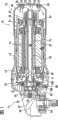
图1示出依据本发明的角磨机的纵截面,Figure 1 shows a longitudinal section through an angle grinder according to the invention,
图2示出依据本发明的角磨机的另一实施例的另一纵截面,以及FIG. 2 shows another longitudinal section of another embodiment of an angle grinder according to the invention, and
图3示出图1角磨机的电动机的一个横截面。FIG. 3 shows a cross section through the electric motor of the angle grinder of FIG. 1 .
实施例Example
图1示出具有一个壳体12的角磨机10,该壳体具有一个前端11和一个后端15。壳体12容纳一个异步电动机14。该异步电动机包括一个可旋转的转子16和一个固定在壳体上的定子20。定子20同心地、通过一个窄的环形间隙径向隔开距离地环绕转子16。转子16无相对转动地配合在一个中心的中空转子轴18上,该转子轴的两端可转动地支承在壳体12中的一个前部和一个后部的滚动轴承22、23上。转子轴在其外圆周的在观察方向上位于左边的端部上承载有一个冷却通风机24。该冷却通风机在壳体12的内空间中产生负压并且因此使冷却空气按箭头27从外部经由壳体12的后端15中的通风缝隙25向内穿过定子20的外表面21和壳体内侧13之间的中间空间38。由此,异步电动机14的外部被冷却。此外,转子16被穿过空心转子轴18内部的空气流冷却。变热了的冷却空气27被角磨机10前端的通风机24通过相应的开口排出。FIG. 1 shows an
转子轴18在其可旋转地支承在前滚动轴承22中的自由端19上承载有一个锥形小齿轮26,该锥形小齿轮通过一个螺母28轴向地并且无相对转动地固定在该转子轴上。锥形小齿轮26与一个盘形齿轮30啮合并与之共同组成一个锥齿轮传动装置32,该锥齿轮传动装置驱动一个与转子轴18成直角设置的从动轴34旋转。该从动轴被设置用于旋转驱动一个未详细示出的旋转磨具、例如磨削盘。The
磨削过程中形成的粉尘和其它颗粒不会随着吸入的冷却空气27进入转子16和定子20之间,因为它们通过一个相应的罩36与其隔离。但由此仍有极少量的冷却空气穿过转子16和定子20之间的环状间隙。因此异步电动机14基本上通过经过定子20的外表面21的空气流进行冷却。为了进行附加的内部冷却,冷却空气27在角磨机10的后端15上通过其构造为敞开的轴端部46的入口进入到转子轴18的空腔44中。变热了的冷却空气27通过径向的开口40排出,这些开口位于转子轴18的壁厚较厚处的轴向区域内,在观察方向上处于通风机24右侧。开口40被构造为横向孔或长形孔。Dust and other particles formed during the grinding process cannot enter with the sucked-in
由于通风机24的通风机叶片240与转子轴18的位于其后的区域(标准压力)之间的负压而形成冷却空气流。转子轴18的长度是这样的,使得其后轴端或其圆形入口42位于磨削粉尘和切屑危及到的壳体区域之外,并且尽可能远离产生磨削粉尘的区域。A cooling air flow is formed as a result of the negative pressure between the
转子轴18可两件式地构成并且包括一个由阶梯轴式的实心材料(Vollmaterial)构成的前部段190。其后部段48由导磁的圆管状材料构成。这些段190和48彼此轴向压紧。其中,空心轴式后部段的接合区域形成一个未详细示出的花键轴轮廓,它具有分别构造为穿孔的花键轴齿槽。这些花键轴齿槽起到径向出口40的作用,热了的冷却空气27可穿过它们流向通风机24并且从该通风机径向向外流出。The
为了减小转子轴18的出口40区域内的空气流阻力,前部段190在其配合在后部段48中的一侧设有一个导流锥体
在异步电动机14的一个试验过的实施例中,空心轴的壁厚至少是2mm,使得在许可的抗弯-和抗扭刚度下为空气的通过形成尽可能大的横截面。因为转子轴18“参与了”转子16的磁力流,因此其壁厚应不小于2mm。In a tried embodiment of the
图2能看到转子轴18的出口40的缝槽状构型,其它部分与图1基本一致。FIG. 2 shows the slot-shaped configuration of the
图3能清楚地看到异步电动机14的横截面和转子轴18的作为空腔44或通道的构型。FIG. 3 clearly shows the cross section of the
Claims (10)
Translated fromChineseApplications Claiming Priority (3)
| Application Number | Priority Date | Filing Date | Title |
|---|---|---|---|
| DE102004063751ADE102004063751A1 (en) | 2004-12-29 | 2004-12-29 | Electric hand tool |
| DE102004063751.2 | 2004-12-29 | ||
| PCT/EP2005/055732WO2006072489A1 (en) | 2004-12-29 | 2005-11-03 | Hand-held electric machine tool |
Publications (2)
| Publication Number | Publication Date |
|---|---|
| CN101116236A CN101116236A (en) | 2008-01-30 |
| CN101116236Btrue CN101116236B (en) | 2010-09-01 |
Family
ID=35482340
Family Applications (1)
| Application Number | Title | Priority Date | Filing Date |
|---|---|---|---|
| CN2005800453782AActiveCN101116236B (en) | 2004-12-29 | 2005-11-03 | Hand-held electric tool |
Country Status (6)
| Country | Link |
|---|---|
| EP (1) | EP1834397B1 (en) |
| KR (1) | KR20070090984A (en) |
| CN (1) | CN101116236B (en) |
| BR (1) | BRPI0506435A (en) |
| DE (1) | DE102004063751A1 (en) |
| WO (1) | WO2006072489A1 (en) |
Cited By (1)
| Publication number | Priority date | Publication date | Assignee | Title |
|---|---|---|---|---|
| US11571800B2 (en) | 2017-02-28 | 2023-02-07 | Mirka Ltd | Cooling arrangement for a power tool and power tool electronics |
Families Citing this family (13)
| Publication number | Priority date | Publication date | Assignee | Title |
|---|---|---|---|---|
| DE102008041370A1 (en)* | 2008-08-20 | 2010-02-25 | Robert Bosch Gmbh | power tool |
| DE102010000830A1 (en)* | 2010-01-12 | 2011-07-14 | Siemens Aktiengesellschaft, 80333 | Electric machine comprises air stream channel with outward radial extension portion within end winding region of stator winding at air outlet side, and fan blades that are arranged in region of outward radial extension portion |
| EP2365610A1 (en)* | 2010-03-09 | 2011-09-14 | Siemens Aktiengesellschaft | Electrical motor incorporating internal rotor cooling |
| JP6225730B2 (en)* | 2014-01-31 | 2017-11-08 | 株式会社豊田自動織機 | Rotating electric machine |
| JP5968575B2 (en) | 2014-03-25 | 2016-08-10 | 三菱電機株式会社 | Fully closed main motor |
| US9821433B2 (en) | 2014-05-20 | 2017-11-21 | Black & Decker Inc. | Particle separation assembly for power tool |
| KR101633422B1 (en)* | 2015-03-13 | 2016-07-08 | 주식회사 씨에스텍 | A non-vibration portable motor |
| DE102018107808A1 (en) | 2018-04-03 | 2019-10-10 | C. & E. Fein Gmbh | Hand tool |
| CN111835126A (en)* | 2019-04-17 | 2020-10-27 | 南京德朔实业有限公司 | Motor and angle mill |
| DE102019111472B3 (en) | 2019-05-03 | 2020-06-25 | Metabowerke Gmbh | Electric motor |
| EP4002655A1 (en)* | 2020-11-24 | 2022-05-25 | Siemens Aktiengesellschaft | Electric motor and robot with electric motor |
| DE102021202994A1 (en)* | 2021-03-26 | 2022-09-29 | Mahle International Gmbh | Rotor for an electric machine |
| CN113937953A (en)* | 2021-10-22 | 2022-01-14 | 中车株洲电机有限公司 | Active air supply cooling permanent magnet motor and electric locomotive |
Citations (6)
| Publication number | Priority date | Publication date | Assignee | Title |
|---|---|---|---|---|
| DE1016153B (en)* | 1954-10-30 | 1957-09-19 | Duss Maschf | Electric hand grinder with fan wheel |
| EP0192469A2 (en)* | 1985-02-19 | 1986-08-27 | Dobson Park Industries Plc | Electric motors and power tools |
| CN2059162U (en)* | 1989-09-21 | 1990-07-11 | 青海水泥厂 | Screw dryer for cement raw material drying grinding head |
| CN1217833A (en)* | 1996-04-17 | 1999-05-26 | 西门子公司 | Rotor windings for motors |
| CN2368609Y (en)* | 1999-04-16 | 2000-03-15 | 劳动部劳动保护科学研究所 | Wet vibratile fiber railing dust-collector |
| EP1345309A2 (en)* | 2002-03-16 | 2003-09-17 | Robert Bosch Gmbh | Electric power tool with a fan |
Family Cites Families (2)
| Publication number | Priority date | Publication date | Assignee | Title |
|---|---|---|---|---|
| US4600848A (en) | 1985-05-24 | 1986-07-15 | Sundstrand Corporation | Cooling of dynamoelectric machines |
| DE29714740U1 (en) | 1996-11-19 | 1997-10-23 | Siemens AG, 80333 München | Electrical machine |
- 2004
- 2004-12-29DEDE102004063751Apatent/DE102004063751A1/ennot_activeWithdrawn
- 2005
- 2005-11-03EPEP05801666.8Apatent/EP1834397B1/ennot_activeNot-in-force
- 2005-11-03CNCN2005800453782Apatent/CN101116236B/enactiveActive
- 2005-11-03WOPCT/EP2005/055732patent/WO2006072489A1/enactiveApplication Filing
- 2005-11-03KRKR1020077014942Apatent/KR20070090984A/ennot_activeCeased
- 2005-11-03BRBRPI0506435-0Apatent/BRPI0506435A/ennot_activeIP Right Cessation
Patent Citations (6)
| Publication number | Priority date | Publication date | Assignee | Title |
|---|---|---|---|---|
| DE1016153B (en)* | 1954-10-30 | 1957-09-19 | Duss Maschf | Electric hand grinder with fan wheel |
| EP0192469A2 (en)* | 1985-02-19 | 1986-08-27 | Dobson Park Industries Plc | Electric motors and power tools |
| CN2059162U (en)* | 1989-09-21 | 1990-07-11 | 青海水泥厂 | Screw dryer for cement raw material drying grinding head |
| CN1217833A (en)* | 1996-04-17 | 1999-05-26 | 西门子公司 | Rotor windings for motors |
| CN2368609Y (en)* | 1999-04-16 | 2000-03-15 | 劳动部劳动保护科学研究所 | Wet vibratile fiber railing dust-collector |
| EP1345309A2 (en)* | 2002-03-16 | 2003-09-17 | Robert Bosch Gmbh | Electric power tool with a fan |
Cited By (1)
| Publication number | Priority date | Publication date | Assignee | Title |
|---|---|---|---|---|
| US11571800B2 (en) | 2017-02-28 | 2023-02-07 | Mirka Ltd | Cooling arrangement for a power tool and power tool electronics |
Also Published As
| Publication number | Publication date |
|---|---|
| EP1834397B1 (en) | 2014-01-08 |
| WO2006072489A1 (en) | 2006-07-13 |
| EP1834397A1 (en) | 2007-09-19 |
| DE102004063751A1 (en) | 2006-07-13 |
| CN101116236A (en) | 2008-01-30 |
| BRPI0506435A (en) | 2006-12-26 |
| KR20070090984A (en) | 2007-09-06 |
Similar Documents
| Publication | Publication Date | Title |
|---|---|---|
| CN101116236B (en) | Hand-held electric tool | |
| US5315193A (en) | Hand-guided machine tool comprising a radial blower | |
| JP7042265B2 (en) | Turbo compressor with separate cooling air passages | |
| JP6127840B2 (en) | Electric tool | |
| US6435828B1 (en) | Split blade radial fan | |
| US20110006621A1 (en) | Power tool | |
| US8698362B2 (en) | Electric power tool with an electric motor | |
| US8039999B2 (en) | Heat dissipation structure for sealed machine tools | |
| US20080150375A1 (en) | Electric power tool | |
| CN203516125U (en) | Fluid pump | |
| RU2508977C2 (en) | Processing machine driven by motor | |
| TW200945740A (en) | Electrical engine | |
| JP2013057286A (en) | Electric blower and vacuum cleaner using the same | |
| EP1065028B1 (en) | A drive spindle | |
| US20070056759A1 (en) | Handheld power tool | |
| CN103066753A (en) | Brushless motor for chain saw | |
| CN101409477A (en) | Airflow cooling pattern for belt-driven vehicle electrical power generator | |
| CN104541745A (en) | Mower | |
| JP4942795B2 (en) | Electric vacuum cleaner | |
| WO2008147981A2 (en) | Centrifugal air blower | |
| CN115313725B (en) | Motor | |
| CN102990118A (en) | High temperature prevention electric hand drill | |
| EP0992692B1 (en) | Fan including a duct for cooling the motor | |
| CN206382992U (en) | Sander | |
| EP3719959B1 (en) | Brushless motor rotor |
Legal Events
| Date | Code | Title | Description |
|---|---|---|---|
| C06 | Publication | ||
| PB01 | Publication | ||
| C10 | Entry into substantive examination | ||
| SE01 | Entry into force of request for substantive examination | ||
| C14 | Grant of patent or utility model | ||
| GR01 | Patent grant |