CN101113530A - Combined type micro-processing device and method combining electrochemical processing and electrolytic polishing - Google Patents
Combined type micro-processing device and method combining electrochemical processing and electrolytic polishingDownload PDFInfo
- Publication number
- CN101113530A CN101113530ACNA2006101037403ACN200610103740ACN101113530ACN 101113530 ACN101113530 ACN 101113530ACN A2006101037403 ACNA2006101037403 ACN A2006101037403ACN 200610103740 ACN200610103740 ACN 200610103740ACN 101113530 ACN101113530 ACN 101113530A
- Authority
- CN
- China
- Prior art keywords
- processing
- metal
- processed
- working liquid
- electrolytic polishing
- Prior art date
- Legal status (The legal status is an assumption and is not a legal conclusion. Google has not performed a legal analysis and makes no representation as to the accuracy of the status listed.)
- Granted
Links
- 238000000034methodMethods0.000titleclaimsabstractdescription30
- 238000005498polishingMethods0.000titleclaimsabstractdescription27
- 239000002184metalSubstances0.000claimsabstractdescription70
- 229910052751metalInorganic materials0.000claimsabstractdescription70
- 239000007788liquidSubstances0.000claimsabstractdescription50
- 238000003754machiningMethods0.000claimsabstractdescription33
- 238000005459micromachiningMethods0.000claimsabstractdescription19
- 239000000243solutionSubstances0.000claimsdescription39
- 238000003860storageMethods0.000claimsdescription13
- XLYOFNOQVPJJNP-UHFFFAOYSA-NwaterSubstancesOXLYOFNOQVPJJNP-UHFFFAOYSA-N0.000claimsdescription13
- 239000002131composite materialSubstances0.000claimsdescription12
- 239000000126substanceSubstances0.000claimsdescription12
- 230000002378acidificating effectEffects0.000claimsdescription7
- 239000003929acidic solutionSubstances0.000claimsdescription6
- 230000007935neutral effectEffects0.000claimsdescription6
- 150000003839saltsChemical class0.000claimsdescription6
- 230000003746surface roughnessEffects0.000abstractdescription8
- 238000002360preparation methodMethods0.000abstractdescription2
- 230000005611electricityEffects0.000abstract1
- 238000010586diagramMethods0.000description6
- 150000001875compoundsChemical class0.000description4
- 239000013078crystalSubstances0.000description4
- 238000005553drillingMethods0.000description2
- 238000005323electroformingMethods0.000description2
- 238000000227grindingMethods0.000description2
- 238000003801millingMethods0.000description2
- 238000012986modificationMethods0.000description2
- 230000004048modificationEffects0.000description2
- 238000003672processing methodMethods0.000description2
- 238000007514turningMethods0.000description2
- QVGXLLKOCUKJST-UHFFFAOYSA-Natomic oxygenChemical compound[O]QVGXLLKOCUKJST-UHFFFAOYSA-N0.000description1
- 230000009286beneficial effectEffects0.000description1
- 238000001816coolingMethods0.000description1
- 230000007547defectEffects0.000description1
- 230000000694effectsEffects0.000description1
- 239000001257hydrogenSubstances0.000description1
- 229910052739hydrogenInorganic materials0.000description1
- 125000004435hydrogen atomChemical class[H]*0.000description1
- 238000004519manufacturing processMethods0.000description1
- 150000002739metalsChemical class0.000description1
- 239000001301oxygenSubstances0.000description1
- 229910052760oxygenInorganic materials0.000description1
- 238000007747platingMethods0.000description1
- 238000007517polishing processMethods0.000description1
Images


Landscapes
- Electrical Discharge Machining, Electrochemical Machining, And Combined Machining (AREA)
Abstract
Description
Translated fromChinese技术领域technical field
本发明涉及一种结合电化学加工与电解抛光的复合式微加工装置及方法The invention relates to a composite micromachining device and method combining electrochemical machining and electrolytic polishing
背景技术Background technique
传统的对一工件进行加工的方式不外乎以刀具对一工件进行车、铣、刨、磨或钻,当然,电铸亦是可行的方法,但不论何种方法,都产生以下缺点:The traditional way of processing a workpiece is nothing more than turning, milling, planing, grinding or drilling a workpiece with a tool. Of course, electroforming is also a feasible method, but no matter what method, it has the following disadvantages:
1、加工速度慢。面对微结构加工需求不断增加的情况,电铸加工是较为可行的方法,但是,其加工速度太慢,无法普遍应用于多样、多量的生产线加工。1. The processing speed is slow. Faced with the ever-increasing demand for microstructure processing, electroforming is a more feasible method, but its processing speed is too slow to be widely used in various and large-volume production line processing.
2、表面粗糙度差。以车、铣、刨、磨或钻对工件进行加工,固然有较快的加工速度,但是,直接接触的加工方式,容易产生压力或热,造成工件微量变形或残留应力,对于成品的表面粗糙度较差,还有冷却、排屑与刀具损坏等问题,若有微结构,刀具的选择更为困难,还可能发生无法加工的情况。2. Poor surface roughness. Processing the workpiece by turning, milling, planing, grinding or drilling, although it has a faster processing speed, but the direct contact processing method is easy to generate pressure or heat, resulting in slight deformation or residual stress of the workpiece, which affects the rough surface of the finished product. There are also problems such as cooling, chip removal and tool damage. If there is a microstructure, the selection of tools is more difficult, and it may not be possible to process.
3、无法对高硬度金属加工。以刀具对工件进行接触式加工,固然速度较快,但是,亦造成刀具磨损,对于高硬度的金属,甚至可能发生刀具无法对工件进行加工的窘境。3. Cannot process high hardness metal. Although the tool is used to process the workpiece by contact, although the speed is faster, it also causes tool wear. For high-hardness metals, the tool may even fail to process the workpiece.
发明内容Contents of the invention
本发明所要解决的主要技术问题在于,克服现有技术存在的上述缺陷,而提供一种结合电化学加工与电解抛光的复合式微加工装置及方法,其具备加工速度快,且可改善表面粗糙度,适合对高硬度金属工件进行加工。The main technical problem to be solved by the present invention is to overcome the above-mentioned defects in the prior art, and provide a composite micromachining device and method combining electrochemical machining and electrolytic polishing, which has fast processing speed and can improve surface roughness. , suitable for processing high hardness metal workpieces.
本发明结合电化学加工与电解抛光的复合式微加工装置是:The composite micromachining device combined with electrochemical machining and electrolytic polishing of the present invention is:
一种结合电化学加工与电解抛光的复合式微加工装置,其特征在于,包括:一电化学加工溶液容纳部,是用以提供一第一工作液体,该第一工作液体为含有水及盐类物质的中性溶液;一电解抛光溶液容纳部,是用以提供一第二工作液体,该第二工作液体为含有水及酸性物质的酸性溶液;一电源部,具有一正极及一负极;一待加工金属固定部,用以固定一待加工金属,该待加工金属连接至该正极;一加工模板组件,具有一微量移动控制部及一具有预定形状的加工模部,该加工模部是连接至该负极;借此,该待加工金属与该加工模部先浸在该第一工作液体中进行第一阶段加工,之后再浸入该第二工作液体中进行第二阶段加工。A composite micromachining device combining electrochemical machining and electrolytic polishing, characterized in that it includes: an electrochemical machining solution container for providing a first working liquid, the first working liquid contains water and salts A neutral solution of substances; an electropolishing solution containing part is used to provide a second working liquid, the second working liquid is an acidic solution containing water and acidic substances; a power supply part has a positive pole and a negative pole; The fixing part of the metal to be processed is used to fix a metal to be processed, and the metal to be processed is connected to the positive electrode; a processing template assembly has a micro movement control part and a processing mold part with a predetermined shape, and the processing mold part is connected to To the negative electrode; thereby, the metal to be processed and the processing mold part are immersed in the first working liquid for the first stage of processing, and then immersed in the second working liquid for the second stage of processing.
前述的结合电化学加工与电解抛光的复合式微加工装置,其特征在于:所述电化学加工溶液容纳部与所述电解抛光溶液容纳部为两个分隔开的贮液槽;所述第一阶段加工为电化学加工;所述第二阶段加工为电解抛光加工。The aforementioned composite micromachining device combined with electrochemical machining and electropolishing is characterized in that: the electrochemical machining solution storage part and the electrolytic polishing solution storage part are two separated liquid storage tanks; the first The stage processing is electrochemical processing; the second stage processing is electrolytic polishing.
前述的结合电化学加工与电解抛光的复合式微加工装置,其中微量移动控制部可控制所述加工模部朝所述待加工金属方向移动,并保持一预定的加工间隙。In the aforementioned composite micromachining device combining electrochemical machining and electrolytic polishing, the micro-movement control part can control the movement of the processing mold part toward the metal to be processed, and maintain a predetermined processing gap.
本发明结合电化学加工与电解抛光的复合式微加工方法是:The compound micromachining method of the present invention in conjunction with electrochemical machining and electrolytic polishing is:
一种结合电化学加工与电解抛光的复合式微加工方法,其特征在于,包括下列步骤:一.准备步骤:准备一电化学加工溶液容纳部、一电解抛光溶液容纳部、一电源部、一待加工金属固定部及一加工模板组件;该电化学加工溶液容纳部是用以提供一第一工作液体,该第一工作液体为含有水及盐类物质的中性溶液;该电解抛光溶液容纳部用以提供一第二工作液体,该第二工作液体为含有水及酸性物质的酸性溶液;该电源部是具有一正极及一负极;该待加工金属固定部是用以固定一待加工金属,该待加工金属连接至该正极;该加工模板组件具有一微量移动控制部及一具有预定形状的加工模部,该加工模部是连接至该负极;二.第一阶段加工步骤:将该待加工金属与该加工模部浸在该第一工作液体中进行第一阶段加工;三.第二阶段加工步骤:将该待加工金属与该加工模部浸在该第二工作液体中进行第二阶段加工;四.完成步骤:在该待加工金属表面加工出相对应该加工模部的形状,得到一成品。A compound micromachining method combining electrochemical machining and electropolishing, characterized in that it comprises the following steps: 1. Preparation step: preparing an electrochemical machining solution container, an electropolishing solution container, a power supply, and a waiting Processing metal fixing part and a processing template assembly; the electrochemical machining solution containing part is used to provide a first working liquid, the first working liquid is a neutral solution containing water and salt substances; the electropolishing solution containing part Used to provide a second working liquid, the second working liquid is an acidic solution containing water and acidic substances; the power supply part has a positive electrode and a negative electrode; the metal fixing part to be processed is used to fix a metal to be processed, The metal to be processed is connected to the positive electrode; the processing template assembly has a micro-movement control part and a processing mold part with a predetermined shape, and the processing mold part is connected to the negative electrode; 2. The first stage of processing steps: the waiting The processing metal and the processing mold are immersed in the first working liquid for the first stage of processing; 3. The second stage of processing steps: the metal to be processed and the processing mold are immersed in the second working liquid for the second Stage processing; 4. Completion step: process the shape corresponding to the mold part to be processed on the surface of the metal to be processed to obtain a finished product.
前述的结合电化学加工与电解抛光的复合式微加工方法,其中电化学加工溶液容纳部与所述电解抛光溶液容纳部为两个分隔开的贮液槽;所述第一阶段加工为电化学加工;所述第二阶段加工为电解抛光加工;所述微量移动控制部是可控制所述加工模部朝该待加工金属方向移动,并保持一预定的加工间隙。The aforementioned composite micromachining method combining electrochemical machining and electrolytic polishing, wherein the electrochemical machining solution container and the electrolytic polishing solution container are two separated liquid storage tanks; the first stage processing is electrochemical processing; the second-stage processing is electrolytic polishing; the micro-movement control part can control the processing mold part to move toward the metal to be processed, and maintain a predetermined processing gap.
本发明的有益效果是,其具备加工速度快,且可改善表面粗糙度,适合对高硬度金属工件进行加工。The beneficial effect of the invention is that it has fast processing speed, can improve surface roughness, and is suitable for processing high-hardness metal workpieces.
附图说明Description of drawings
下面结合附图和实施例对本发明进一步说明。The present invention will be further described below in conjunction with the accompanying drawings and embodiments.
图1是本发明的实施例示意图Fig. 1 is a schematic diagram of an embodiment of the present invention
图2是图1所示实施例的部分结构的放大平面示意图Fig. 2 is the enlarged schematic plan view of the partial structure of the embodiment shown in Fig. 1
图3A是本发明的电化学加工的实施例的示意图Figure 3A is a schematic diagram of an embodiment of the electrochemical machining of the present invention
图3B是本发明的电解抛光的实施例的示意图Figure 3B is a schematic diagram of an embodiment of electropolishing of the present invention
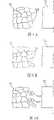
图4A、图4B、图4C及图4D是本发明的复合式微加工方法的部分过程的示意图Fig. 4A, Fig. 4B, Fig. 4C and Fig. 4D are the schematic diagrams of the partial process of the hybrid micromachining method of the present invention
图5是本发明的复合式微加工方法的流程图Fig. 5 is the flowchart of compound micromachining method of the present invention
图6A、图6B及图6C是本发明的电化学加工的细部过程的示意图Fig. 6A, Fig. 6B and Fig. 6C are the schematic diagrams of the detail process of the electrochemical machining of the present invention
图7A、图7B及图7C是本发明的电解抛光的细部过程示意图Figure 7A, Figure 7B and Figure 7C are schematic diagrams of the detailed process of electrolytic polishing of the present invention
图中标号说明:Explanation of symbols in the figure:
10电化学加工溶液容纳部 11第一工作液体10 Electrochemical
20电解抛光溶液容纳部 21第二工作液体20
30电源部 31正极30
32负极 40待加工金属固定部32
41待加工金属 41A金属晶粒41 metal to be processed 41A metal grain
41B尖端部 41C内凹部41B tip part 41C inner concave part
411凹部 50加工模板组件411
51微量移动控制部 52加工模部51 Micro
61准备步骤 62第一阶段加工步骤61
63第二阶段加工步骤 64完成步骤63 Second
70黏稠层 71内黏稠层70 viscous layer 71 inner viscous layer
72外黏稠层 G加工间隙72 outer viscous layer G processing clearance
D1第一深度 D2第二深度D1 first depth D2 second depth
L1第一距离 L2第二距离L1 first distance L2 second distance
具体实施方式Detailed ways
参阅图1、图2,本发明为一种『结合电化学加工与电解抛光的复合式微加工装置』,其包括:Referring to Fig. 1, Fig. 2, the present invention is a kind of " compound micromachining device combining electrochemical machining and electrolytic polishing ", and it comprises:
一电化学加工溶液容纳部10,是用以提供一第一工作液体11,该第一工作液体11为含有水及盐类物质的中性溶液;An electrochemical
一电解抛光溶液容纳部20,是用以提供一第二工作液体21,该第二工作液体21为含有水及酸性物质的酸性溶液;An
一电源部30,是至少具有一正极31及一负极32;A
一待加工金属固定部40,是用以固定一待加工金属41,该待加工金属41是连接至该正极31;A metal to be processed fixing
一加工模板组件50,其具有:A
一微量移动控制部51;A micro
一具有预定形状的加工模部52,该加工模部52是连接至该负极32,且受该微量移动控制部51驱动。A
借此,该待加工金属41与该加工模部52是先浸在该第一工作液体21进行第一阶段加工(在本发明中为电化学加工)后,再浸入该第二工作液体21进行第二阶段加工(在本发明中为电解抛光加工)。In this way, the
实际上,该电化学加工溶液容纳部10与该电解抛光溶液容纳部20为两个分隔开的贮液槽。In fact, the electrochemical machining
该微量移动控制部51是控制该加工模部52朝该待加工金属41方向移动,且该加工模部52与该待加工金属41间保持一预定的加工间隙G(参阅图4A)。The slight
本发明的微加工方法包括下列步骤(参阅图1及图5):The micromachining method of the present invention comprises the following steps (referring to Fig. 1 and Fig. 5):
一.准备步骤61:准备一电化学加工溶液容纳部10、一电解抛光溶液容纳部20、一电源部30、一待加工金属固定部40及一加工模板组件50;其中,该电化学加工溶液容纳部10是用以提供一第一工作液体11,该第一工作液体11为含有水及盐类物质的中性溶液;该电解抛光溶液容纳部20是用以提供一第二工作液体21,该第二工作液体21为含有水及酸性物质的酸性溶液;该电源部30是具有一正极31及一负极32;该待加工金属固定部40是用以固定一待加工金属41,该待加工金属41是连接至该正极31;该加工模板组件50是具有一微量移动控制部51及一具有预定形状的加工模部52,该加工模部52是连接至该负极32。1. Preparatory step 61: Prepare an electrochemical
二.第一阶段加工步骤62:参阅图3A,将该待加工金属41与该加工模部52浸在该第一工作液体11中(可以说是浸在该电化学加工溶液容纳部10中),启动该电源部30,借由该正极31使该待加工金属41带正电,并借由该负极32使该加工模部52带负电;配合该第一工作液体11对该待加工金属41进行第一阶段加工(在本发明中为电化学加工);2. The first stage of processing step 62: referring to Fig. 3A, immerse the
三.第二阶段加工步骤63:参阅图3B,将该待加工金属41与该加工模部52浸在该第二工作液体21(可以说是浸在该电解抛光溶液容纳部20中),启动该电源部30及该微量移动控制部51,借由该正极31使该待加工金属41带正电,并借由该负极32使该加工模部52带负电,借由该微量移动控制部51驱动该加工模部52靠近该待加工金属41,再配合该第二工作液体21对该待加工金属41进行第二阶段加工(在本发明中为电解抛光加工);Three. The second stage processing step 63: Referring to Fig. 3B, immerse the
四.完成步骤64:在该待加工金属41表面加工出相对应该加工模部52的形状,得到一成品。4. Complete step 64: process the shape corresponding to the
更详细的讲,在第一阶段加工步骤61的部分,最初的加工状态如图4A所示,该待加工金属41与该加工模部52均浸在该第一工作液体11中,并有一加工间隙G。通电后,该加工模部52逐渐朝该待加工金属41加工出较浅的凹部411(如图4B所示),该较浅的凹部411具有一第一深度D1;该加工模部52移动的距离与速度是由该微量移动控制部51控制。In more detail, in the part of the
继续加工一段时间后,该加工模部52逐渐朝该待加工金属41加工出一较深的凹部411,该较深的凹部411具有一第二深度D2(如图4C所示)。值得注意的是,在第一阶段时,均属于电化学加工。After continuing processing for a period of time, the
在第二阶段加工步骤62的部分,将该待加工金属41与该加工模部52浸在该第二工作液体21中,其加工装置如图3B所示,此时,该加工模部52与该待加工金属41保持该加工间隙G,并进行电解抛光加工(如图4D所示),因此,可以对该较深的凹部411进行较细微的表面粗糙度改善。In the part of the
有关此电化学加工的原理,请参阅图6A、图6B及图6C,原本该待加工金属41的金属晶粒41A是紧密相结合(如图6A所示)。逐渐的,该待加工金属41的金属晶粒41A间的边界会逐渐被渗透并破坏(如图6B所示),最后,位于最外层的金属晶粒41A会脱离(如图6C所示),虽然这种加工的速度较快,但是表面较为粗糙。Please refer to FIG. 6A , FIG. 6B and FIG. 6C for the principle of this electrochemical machining. Originally, the
其次,关于此电解抛光加工的原理,请参阅图7A、图7B及图7C,将电化学加工处理后的待加工金属41的金属晶粒41A改浸在第二工作液体21中(如图7A所示),由于该第二工作液体21含有水及酸性物质,会形成一黏稠层70(如图7B所示),此黏稠层70具有一较内侧且黏度较高的内黏稠层71与一较外侧且黏度较低的外黏稠层72,同时,在接近带正电的金属晶粒41A产生氢气,在接近带负电的加工模部52则产生氧气,为一典型的逆电镀反应。Secondly, regarding the principle of this electrolytic polishing process, please refer to FIG. 7A, FIG. 7B and FIG. 7C, the
由图7B可看出,该待加工金属41的尖端部41B与该加工模部52间形成一第一距离L1,同时,该待加工金属41的内凹部41C与该加工模部52间形成一第二距离L2,由于该第一距离L1比第二距离L2小,所以通过的电流密度较大,因此,尖端部41B会先被移除(如图7C所示),借此,虽然移除的速度较慢,但是可以有效的改善表面粗糙度。As can be seen from FIG. 7B, a first distance L1 is formed between the tip portion 41B of the metal to be processed 41 and the processing die
本发明的优点及功效可归纳为:Advantage of the present invention and effect can be summarized as:
1、加工速度快。本发明巧妙的结合电化学加工与电解抛光两种加工方式,在第一阶段加工步骤中,由于加工速度较快,可以快速的粗加工至大约的尺寸,亦即,概略的形状可以很快的加工出来,故,加工速度快。1. Fast processing speed. The present invention cleverly combines the two processing methods of electrochemical machining and electrolytic polishing. In the first stage of processing steps, due to the fast processing speed, it can be quickly roughed to approximate dimensions, that is, the rough shape can be quickly processed. Processing out, therefore, the processing speed is fast.
2、可改善表面粗糙度。本发明的第二阶段加工步骤中,利用电解抛光加工,配合距离较近者电流密度较大的特点,将较凸出的金属晶粒部分优先移除,所以,等于是有效的改善表面粗糙度。2. It can improve the surface roughness. In the second processing step of the present invention, electrolytic polishing is used to remove the protruding metal crystal grains preferentially in accordance with the characteristic that the distance is closer and the current density is higher. Therefore, it is equivalent to effectively improving the surface roughness. .
3、适合对高硬度金属工件进行加工。本发明采用非接触式加工,纵使是具有微结构的高硬度金属工件,也可进行加工。3. Suitable for processing high hardness metal workpieces. The invention adopts non-contact processing, even if it is a high-hardness metal workpiece with microstructure, it can also be processed.
以上所述,仅是本发明的较佳实施例而已,并非对本发明作任何形式上的限制,凡是依据本发明的技术实质对以上实施例所作的任何简单修改、等同变化与修饰,均仍属于本发明技术方案的范围内。The above are only preferred embodiments of the present invention, and are not intended to limit the present invention in any form. Any simple modifications, equivalent changes and modifications made to the above embodiments according to the technical essence of the present invention still belong to within the scope of the technical solutions of the present invention.
Claims (5)
Translated fromChinesePriority Applications (1)
| Application Number | Priority Date | Filing Date | Title |
|---|---|---|---|
| CN2006101037403ACN101113530B (en) | 2006-07-28 | 2006-07-28 | Composite micromachining device and method combining electrochemical machining and electrolytic polishing |
Applications Claiming Priority (1)
| Application Number | Priority Date | Filing Date | Title |
|---|---|---|---|
| CN2006101037403ACN101113530B (en) | 2006-07-28 | 2006-07-28 | Composite micromachining device and method combining electrochemical machining and electrolytic polishing |
Publications (2)
| Publication Number | Publication Date |
|---|---|
| CN101113530Atrue CN101113530A (en) | 2008-01-30 |
| CN101113530B CN101113530B (en) | 2010-09-08 |
Family
ID=39022053
Family Applications (1)
| Application Number | Title | Priority Date | Filing Date |
|---|---|---|---|
| CN2006101037403AExpired - Fee RelatedCN101113530B (en) | 2006-07-28 | 2006-07-28 | Composite micromachining device and method combining electrochemical machining and electrolytic polishing |
Country Status (1)
| Country | Link |
|---|---|
| CN (1) | CN101113530B (en) |
Cited By (2)
| Publication number | Priority date | Publication date | Assignee | Title |
|---|---|---|---|---|
| CN102251268A (en)* | 2010-05-19 | 2011-11-23 | 易生科技(北京)有限公司 | Bracket polishing device and polishing method in electrochemical polishing |
| CN102107304B (en)* | 2009-12-25 | 2014-04-09 | 财团法人金属工业研究发展中心 | Electrochemical processing equipment and processing method and electrode unit thereof |
Family Cites Families (2)
| Publication number | Priority date | Publication date | Assignee | Title |
|---|---|---|---|---|
| US5320721A (en)* | 1993-01-19 | 1994-06-14 | Corning Incorporated | Shaped-tube electrolytic polishing process |
| CN1104297C (en)* | 1998-04-06 | 2003-04-02 | 皇家菲利浦电子有限公司 | Method and apparatus for electrochemical machining of workpiece |
- 2006
- 2006-07-28CNCN2006101037403Apatent/CN101113530B/ennot_activeExpired - Fee Related
Cited By (5)
| Publication number | Priority date | Publication date | Assignee | Title |
|---|---|---|---|---|
| CN102107304B (en)* | 2009-12-25 | 2014-04-09 | 财团法人金属工业研究发展中心 | Electrochemical processing equipment and processing method and electrode unit thereof |
| CN102251268A (en)* | 2010-05-19 | 2011-11-23 | 易生科技(北京)有限公司 | Bracket polishing device and polishing method in electrochemical polishing |
| CN102251268B (en)* | 2010-05-19 | 2013-05-22 | 易生科技(北京)有限公司 | Bracket polishing device and polishing method in electrochemical polishing |
| CN103352246A (en)* | 2010-05-19 | 2013-10-16 | 易生科技(北京)有限公司 | Polishing device and method for stent |
| CN103352246B (en)* | 2010-05-19 | 2015-08-19 | 易生科技(北京)有限公司 | Support burnishing device and method |
Also Published As
| Publication number | Publication date |
|---|---|
| CN101113530B (en) | 2010-09-08 |
Similar Documents
| Publication | Publication Date | Title |
|---|---|---|
| Sonia et al. | Influence of ultrasonic vibration assistance in manufacturing processes: A Review | |
| CN101693313B (en) | Combined EDM milling method for micro three-dimensional structure | |
| CN104923869B (en) | The controllable combined machining method of micro hole vibrating electrode electric spark and electrolysis and vibrational system | |
| CN108179461B (en) | A kind of hollow metal part inner wall polishing method | |
| Fayazfar et al. | An overview of surface roughness enhancement of additively manufactured metal parts: a path towards removing the post-print bottleneck for complex geometries | |
| US6558231B1 (en) | Sequential electromachining and electropolishing of metals and the like using modulated electric fields | |
| CN204123241U (en) | Based on the ultra-precision processing apparatus of non-Newtonian shear thickening and electrolysis complex effect | |
| CN104394246A (en) | Mobile phone frame and processing method thereof | |
| CN113201738B (en) | An electrochemical surface treatment method for selective laser melting of AlSi10Mg forming workpieces | |
| CN102009388A (en) | Miniature metal-based grinding wheel on-line electrolytic electric spark dressing device and method | |
| CN103817388B (en) | A kind of device for preparing the fine milling cutter of screw type hard alloy | |
| CN113584568B (en) | Electrochemical high-precision polishing method for metal fine structure | |
| CN201988815U (en) | Electrochemical deburring machine | |
| CN101113530B (en) | Composite micromachining device and method combining electrochemical machining and electrolytic polishing | |
| CN102320023B (en) | Controllable precision finishing process for surface of high-speed tool constraint abrasive part | |
| CN109234506A (en) | A kind of laser assisted mechanic shot peening forms the complex method of gradient nano structure | |
| CN102494042B (en) | Method for manufacturing constant velocity universal joint maintaining rack | |
| CN104907654B (en) | A kind of electrolytic method that Surface Texture is carried out using cellular plastic plate | |
| US20070138023A1 (en) | Combined electrochemical machining and electropolishing micro-machining apparatus and method | |
| CN105562851B (en) | A kind of soft electrode electric discharge machining apparatus based on liquid metal and porous ceramic | |
| JP2009178770A (en) | Method of machining mold member, method of producing the same, extrusion die, method for production of extruding material, and extruding material | |
| CN100560809C (en) | Electrolytic Machining Method of Micro Texture on Outer Surface of Cylindrical Rotary Parts | |
| CN109226917B (en) | Surface roughening method based on electric discharge machining | |
| JP2013086202A (en) | Electrochemical machining apparatus and electrochemical machining method | |
| Borovskii et al. | Ultraprecision machining of brittle optical materials |
Legal Events
| Date | Code | Title | Description |
|---|---|---|---|
| C06 | Publication | ||
| PB01 | Publication | ||
| C10 | Entry into substantive examination | ||
| SE01 | Entry into force of request for substantive examination | ||
| C14 | Grant of patent or utility model | ||
| GR01 | Patent grant | ||
| C17 | Cessation of patent right | ||
| CF01 | Termination of patent right due to non-payment of annual fee | Granted publication date:20100908 Termination date:20110728 |