CN101110661B - Jitter Buffer Adjustment Method for Circuit Simulation System - Google Patents
Jitter Buffer Adjustment Method for Circuit Simulation SystemDownload PDFInfo
- Publication number
- CN101110661B CN101110661BCN2007101300145ACN200710130014ACN101110661BCN 101110661 BCN101110661 BCN 101110661BCN 2007101300145 ACN2007101300145 ACN 2007101300145ACN 200710130014 ACN200710130014 ACN 200710130014ACN 101110661 BCN101110661 BCN 101110661B
- Authority
- CN
- China
- Prior art keywords
- jitter
- threshold
- jitter buffer
- delay
- new
- Prior art date
- Legal status (The legal status is an assumption and is not a legal conclusion. Google has not performed a legal analysis and makes no representation as to the accuracy of the status listed.)
- Expired - Fee Related
Links
Images


Landscapes
- Data Exchanges In Wide-Area Networks (AREA)
Abstract
Translated fromChinese
Description
Translated fromChinese技术领域technical field
本发明涉及电路仿真(CES,Circuit Emulation Service)领域,特别是涉及一种电路仿真系统的抖动缓存调整方法。 The invention relates to the field of circuit emulation (CES, Circuit Emulation Service), in particular to a method for adjusting a jitter buffer of a circuit emulation system. the
背景技术Background technique
随着IP技术的普及,在分组交换网络上承载多种业务越来越成为网络技术发展的趋势,其中一种典型的业务就是利用分组交换网络传输传统的时分复用(TDM,Time Division Multiplexing)网络中的各种电路业务,它所运用的技术就是CES技术。 With the popularization of IP technology, it is becoming more and more a trend of network technology development to carry multiple services on the packet switching network. One of the typical services is to use the packet switching network to transmit the traditional Time Division Multiplexing (TDM, Time Division Multiplexing) The technology used by various circuit services in the network is CES technology. the
CES技术的基本原理如图1所示,该技术在分组交换网(PSN,Packet SwitchNetwork)上搭建一个通道,通过在源端增加包头,用分组包封装每个TDM数据帧,再通过分组交换网中所搭建的通道传送到目的端。目的端在收到数据包后重新生成同步时钟信号,同时去掉数据包中的包头,将剩下的数据还原成原始的TDM数据帧,从而使网络两端的TDM设备不需要关心其连接的网络是否为TDM网络。图1中的互通单元(IWF,InterWork Function)设备起到CES网关的作用,是TDM数据帧进出分组交换网络的节点。 The basic principle of CES technology is shown in Figure 1. This technology builds a channel on the packet switching network (PSN, Packet Switch Network). By adding a header at the source end, each TDM data frame is encapsulated with a packet packet, and then passed through the packet switching network. The channel built in is sent to the destination. After receiving the data packet, the destination regenerates the synchronous clock signal, removes the packet header in the data packet, and restores the remaining data to the original TDM data frame, so that the TDM devices at both ends of the network do not need to care whether the network they are connected to is for TDM networks. The interworking unit (IWF, InterWork Function) device in Figure 1 acts as a CES gateway and is a node for TDM data frames to enter and exit the packet switching network. the
由于分组交换网是一种尽力而为的网络,在传送TDM业务时难免会由于分组交换网络的延时引入一些不确定因素。例如:分组包存储转发引入的延时抖动(PDV,Packet Delay Variation),需要在目的端被吸收,否则会影响输出端信号时钟的质量。这就需要CES系统的目的端设备提供一种抖动缓存来吸收PDV,该抖动缓存起到的作用是:将分组包调整到正确序列中,并根据需要对分组进行适当延时,以补偿其网络延时中的偏差。另外,TDM业务需要从分组包中恢复出业务携带的时钟信息,这个步骤一般由定时恢复算法来完成。Since the packet switching network is a best-effort network, it is inevitable that some uncertain factors will be introduced due to the delay of the packet switching network when transmitting TDM services. For example: Packet Delay Variation (PDV, Packet Delay Variation) introduced by packet storage and forwarding needs to be absorbed at the destination end, otherwise it will affect the quality of the signal clock at the output end. This requires the destination device of the CES system to provide a jitter buffer to absorb PDV. The function of the jitter buffer is to adjust the packet into the correct sequence, and appropriately delay the packet according to the need to compensate for its network delay. Deviation in delay. In addition, the TDM service needs to recover the clock information carried by the service from the packet, and this step is generally completed by a timing recovery algorithm.
图2所示为CES系统中抖动缓存的结构,该缓存一般是一个先进先出(FIFO,First In First Out)缓冲器,其中,写指针按照实际收到的数据包的顺序依次写入,由于分组包网络延时的偏差,目的端收到分组包的次序可能已经被打乱,如果收到早到的分组包,则需要空出相应的位置留给晚到的分组包,这样可以对分组包的乱序进行调整。同时,读指针按照时钟恢复算法恢复出的时钟依次将分组包读出。 Figure 2 shows the structure of the jitter buffer in the CES system. The buffer is generally a first-in-first-out (FIFO, First In First Out) buffer, where the write pointers are written sequentially in the order of the actually received data packets, because Due to the deviation of packet network delay, the order of packets received by the destination end may have been disrupted. If an early packet is received, the corresponding position needs to be reserved for a late packet, so that the packets can be The out-of-order of packets is adjusted. At the same time, the read pointer sequentially reads out the packets according to the clock recovered by the clock recovery algorithm. the
由于写指针在缓存中写入分组包的位置不固定,所以写指针相对于读指针的位置会存在一个随机的抖动,该抖动在图2中表现为:写指针在所利用到的缓存最大深度和所利用到的缓存最小深度之间来回抖动,这个抖动范围就是分组交换网络的PDV,如果抖动缓存足够大,定时恢复算法就能够恢复出的平稳的TDM业务时钟,此时抖动缓存能很好地吸收分组交换网络的延时抖动。 Since the position where the write pointer writes packets in the cache is not fixed, there will be a random jitter in the position of the write pointer relative to the read pointer. This jitter is shown in Figure 2: The jitter range is the PDV of the packet switching network. If the jitter buffer is large enough, the timing recovery algorithm can restore a stable TDM service clock. At this time, the jitter buffer can be very good. It can effectively absorb the delay jitter of the packet switching network. the
所述抖动缓存的大小与分组交换网络的PDV密切相关,在分组包经过的网络发生变化时,例如网络节点发生变化,或者网络负载发生变化,会引起PDV的变化。这样,就要求抖动缓存大小的设置应该能随PDV而动态变化:分组交换网络PDV变大时,必须增大抖动缓存,以吸收更大的PDV,否则会导致抖动缓存的溢出,无法恢复出正确的时钟信息和TDM数据帧;当PDV减小时,必须减小抖动缓存,否则由抖动缓存所形成的延时会一直很大,从而会造成TDM业务传输质量下降。 The size of the jitter buffer is closely related to the PDV of the packet switching network. When the network through which the packet passes changes, for example, the network node changes or the network load changes, the PDV will change. In this way, it is required that the setting of the jitter buffer size should be able to change dynamically with the PDV: when the PDV of the packet switching network becomes larger, the jitter buffer must be increased to absorb the larger PDV, otherwise the jitter buffer will overflow and the correct clock information and TDM data frames; when the PDV decreases, the jitter buffer must be reduced, otherwise the delay formed by the jitter buffer will always be large, which will cause the degradation of TDM service transmission quality. the
现有技术中,对于CES系统抖动缓存的设置,一般是依赖于经验手工完成,或是基于对大量静态统计数据分析的基础上完成,或是通过监测业务的实际运行情况,例如TDM业务是否延时过大或是否有丢包的情形来确定。这些方法都不是自动调整抖动缓存的技术,容易造成TDM业务的传输质量下降甚至中断,或者由于抖动缓存设置过大而造成延时太大,传输质量下降。 In the prior art, the setting of the jitter buffer of the CES system is generally done manually based on experience, or based on the analysis of a large amount of static statistical data, or by monitoring the actual operation of the service, such as whether the TDM service is delayed or not. It is determined whether the time is too large or whether there is a packet loss. These methods are not technologies for automatically adjusting the jitter buffer, which may easily cause the transmission quality of the TDM service to decline or even be interrupted, or the delay due to the excessive setting of the jitter buffer will be too large and the transmission quality will be reduced. the
发明内容Contents of the invention
有鉴于此,本发明的主要目的在于提供一种CES系统的抖动缓存调整方法,使分组交换网络引入的PDV能够尽可能地被吸收,同时又使CES引入的延时能够被优化。 In view of this, the main purpose of the present invention is to provide a method for adjusting the jitter buffer of the CES system, so that the PDV introduced by the packet switching network can be absorbed as much as possible, and the delay introduced by the CES can be optimized at the same time. the
为达到上述目的,本发明的技术方案是这样实现的: In order to achieve the above object, technical solution of the present invention is achieved in that way:
一种电路仿真系统的抖动缓存调整方法,设置预定时间段以及抖动上门限J1和抖动下门限J2,该方法包括以下步骤:监测一预定时间段内的抖动缓存,如果监测到的网络延时抖动Jk大于所述抖动上门限J1,则执行步骤B,如果所述延时抖动Jk小于所述抖动下门限J2,则执行步骤C,如果所述延时抖动Jk在所述抖动上门限J1和抖动下门限J2之间,则返回步骤A继续监测下一预定时间段;增大抖动缓存深度J0,以及调整所述抖动上门限J1和抖动下门限J2,使得所述延时抖动Jk在所述抖动上门限J1和抖动下门限J2之间;减缓读出数据的速率,将抖动缓存的写指针移动到增大后的新抖动缓存深度J0的中心位置,其中读出数据速率的变化率由所传输的时分复用业务定时指标要求决定,且所述时分复用业务定时指标要求随实际应用场合而有所不同;减小抖动缓存深度J0,以及调整所述抖动上门限J1和抖动下门限J2,使得所述延时抖动Jk在所述抖动上门限J1和抖动下门限J2之间;其中,J2<J1<J0。 A method for adjusting a jitter buffer of a circuit emulation system, setting a predetermined time period and an upper jitter threshold J1 and a lower jitter threshold J2, the method comprising the following steps: monitoring the jitter buffer within a predetermined time period, if the detected network delay jitter Jk is greater than the jitter upper threshold J1, then perform step B, if the delay jitter Jk is less than the jitter lower threshold J2, then perform step C, if the delay jitter Jk is within the jitter upper threshold J1 and jitter Between the lower threshold J2, then return to step A and continue to monitor the next predetermined period of time; increase the jitter buffer depth J0, and adjust the jitter upper threshold J1 and jitter lower threshold J2, so that the delay jitter Jk is within the jitter Between the upper threshold J1 and the lower jitter threshold J2; slow down the rate of reading data, and move the write pointer of the jitter buffer to the center position of the increased new jitter buffer depth J0, wherein the change rate of the read data rate is determined by the transmitted The timing index requirements of the time-division multiplexing service are determined, and the timing index requirements of the time-division multiplexing service vary with actual application occasions; reduce the jitter buffer depth J0, and adjust the jitter upper threshold J1 and jitter lower threshold J2, The delay jitter Jk is made to be between the upper jitter threshold J1 and the lower jitter threshold J2; wherein, J2<J1<J0. the
增大抖动缓存深度步骤或减小抖动缓存深度步骤中,增大或减小后的新抖动缓存深度J0与所述延时抖动Jk满足以下关系:所述延时抖动Jk等于新抖动缓存深度J0的70%;且调整后的抖动上下门限的值满足:抖动上门限J1和抖动下门限J2分别为新抖动缓存深度J0的80%和20%。 In the step of increasing the jitter buffer depth or reducing the jitter buffer depth, the increased or reduced new jitter buffer depth J0 and the delay jitter Jk satisfy the following relationship: the delay jitter Jk is equal to the new jitter buffer depth J0 and the adjusted values of the upper and lower thresholds of jitter satisfy: the upper and lower thresholds J1 of jitter and the lower threshold J2 of jitter are respectively 80% and 20% of the new jitter buffer depth J0. the
其中,所述监测为:监测一个以上预定时间段;如果在每个预定时间段内,延时抖动Jk都大于抖动上门限J1,则执行增大抖动缓存深度步骤;如果在每个预定时间段内,延时抖动Jk都小于抖动下门限J2,则执行减小抖动缓存深度步骤;否则继续执行步骤A进行监测。 Wherein, the monitoring is: monitor more than one predetermined time period; if within each predetermined time period, the delay jitter Jk is greater than the jitter upper threshold J1, then perform the step of increasing the jitter buffer depth; if within each predetermined time period If the delay jitter Jk is less than the lower jitter threshold J2, then execute the step of reducing the jitter buffer depth; otherwise, continue to execute step A for monitoring. the
其中,所述检测步骤之前还进一步包括初始化步骤:业务连通后,监测一个时间段的网络延时抖动,然后根据该监测到的延时抖动设置初始的抖动缓存深度J0。 Wherein, the detection step further includes an initialization step: after the service is connected, monitor the network delay jitter for a period of time, and then set the initial jitter buffer depth J0 according to the monitored delay jitter. the
本发明的电路仿真系统的抖动缓存调整方法中,增大抖动缓存深度步骤还包括:减缓读出数据的速率,将抖动缓存的写指针移动到增大后的新抖动缓存深度J0的中心位置,其中读出数据速率的变化率由所传输的时分复用业务定时指标要求决定。 In the jitter buffer adjustment method of the circuit simulation system of the present invention, the step of increasing the jitter buffer depth further includes: slowing down the rate of reading data, moving the write pointer of the jitter buffer to the central position of the increased new jitter buffer depth J0, The rate of change of the read data rate is determined by the timing index requirements of the transmitted time division multiplexing service. the
其中,所述新抖动缓存深度J0的值与所述延时抖动Jk满足以下关系:所述延时抖动Jk等于新抖动缓存深度J0的70%,且调整后的抖动上门限J1和抖动下门限J2分别为新抖动缓存深度J0的80%和20%。 Wherein, the value of the new jitter buffer depth J0 and the delay jitter Jk satisfy the following relationship: the delay jitter Jk is equal to 70% of the new jitter buffer depth J0, and the adjusted jitter upper threshold J1 and jitter lower threshold J2 is 80% and 20% of the new dither buffer depth J0, respectively. the
本发明的电路仿真系统的抖动缓存调整方法中,减小抖动缓存深度步骤具体为:设置减小的新抖动缓存深度J0,并加快读出数据的速率,将抖动缓存的写指针移动到所述新抖动缓存深度J0的中心位置,其中读出数据速率的变化率由所传输的时分复用业务定时指标要求决定;设置新的抖动上门限J1和抖动下门限J2,使得新的设置满足J2<Jk<J1<J0。 In the jitter buffer adjustment method of the circuit emulation system of the present invention, the step of reducing the jitter buffer depth is specifically: setting the reduced new jitter buffer depth J0, and speeding up the rate of reading data, and moving the write pointer of the jitter buffer to the The central position of the new jitter buffer depth J0, where the change rate of the read data rate is determined by the timing index requirements of the transmitted time-division multiplexing service; set a new jitter upper threshold J1 and a jitter lower threshold J2, so that the new setting meets J2< Jk<J1<J0. the
其中,所述新抖动缓存深度J0的值与所述延时抖动Jk满足以下关系:所述延时抖动Jk等于新抖动缓存深度J0的70%,且调整后的抖动上门限J1和抖动下门限J2分别为新抖动缓存深度J0的80%和20%。 Wherein, the value of the new jitter buffer depth J0 and the delay jitter Jk satisfy the following relationship: the delay jitter Jk is equal to 70% of the new jitter buffer depth J0, and the adjusted jitter upper threshold J1 and jitter lower threshold J2 is 80% and 20% of the new dither buffer depth J0, respectively. the
本发明的电路仿真系统的抖动缓存调整方法中,以所述预定时间段为周期,重复执行步骤检测步骤、增大抖动缓存深度步骤和减小抖动缓存深度步骤。 In the jitter buffer adjustment method of the circuit emulation system of the present invention, the steps of detecting, increasing the depth of the jitter buffer and reducing the depth of the jitter buffer are repeatedly executed with the predetermined period of time as a cycle. the
本发明所提供的CES系统的抖动缓存调整方法,根据监测到的网络延时抖动的实际情况自动调整抖动缓存大小,不需要人工按照经验或统计分析设置更改抖动缓存的大小,由此简化了操作流程,能够提供适当的抖动缓存以吸收延时抖动,优化了TDM传输质量,具体来说,调整抖动缓存的过程完全自动,不需要用户参与。 The jitter buffer adjustment method of the CES system provided by the present invention automatically adjusts the size of the jitter buffer according to the actual situation of the monitored network delay jitter, and does not need to manually change the size of the jitter buffer according to experience or statistical analysis settings, thereby simplifying the operation The process can provide an appropriate jitter buffer to absorb delay jitter and optimize the TDM transmission quality. Specifically, the process of adjusting the jitter buffer is completely automatic and does not require user participation. the
本发明优化了由于抖动缓存所产生的延时,使CES系统由于抖动缓存所产生的延时在PDV减小的情况下尽可能减小;并且,在调整抖动缓存的过程中,本发明按照所传输业务的指标要求决定调整的速度,可以做到TDM业务的时钟传递质量不受影响。 The present invention optimizes the delay caused by the jitter buffer, so that the delay generated by the CES system due to the jitter buffer can be reduced as much as possible when the PDV is reduced; and, in the process of adjusting the jitter buffer, the present invention according to the The index of the transmission service determines the speed of adjustment, so that the clock transmission quality of the TDM service will not be affected. the
附图说明Description of drawings
图1为现有技术中CES系统的结构示意图; Fig. 1 is the structural representation of CES system in the prior art;
图2为现有技术中CES系统抖动缓存的结构示意图; Fig. 2 is the structural representation of CES system jitter cache in the prior art;
图3为本发明CES系统抖动缓存调整方法的流程图; Fig. 3 is the flow chart of the CES system jitter buffer adjustment method of the present invention;
图4为本发明CES系统抖动缓存调整方法中增大抖动缓存的实现流程图;Fig. 4 is the implementation flowchart of increasing the jitter buffer in the CES system jitter buffer adjustment method of the present invention;
图5为本发明CES系统抖动缓存调整方法中减小抖动缓存的实现流程图。 FIG. 5 is a flow chart of reducing the jitter buffer in the method for adjusting the jitter buffer of the CES system according to the present invention. the
具体实施方式Detailed ways
下面结合附图及具体实施例对本发明再作进一步详细的说明。为了方便描述,以下将分组交换网络简称为网络。 The present invention will be further described in detail below in conjunction with the accompanying drawings and specific embodiments. For convenience of description, the packet switching network is referred to as the network for short below. the
如图3所示,本发明的CES系统的抖动缓存调整方法,包括以下步骤: As shown in Figure 3, the jitter buffer adjustment method of the CES system of the present invention comprises the following steps:
步骤101:设置并初始化CES系统的抖动缓存。 Step 101: Setting and initializing the jitter buffer of the CES system. the
业务连通后,目的端获得网络的PDV,然后设置初始的抖动缓存长度。这里,业务连通是指网络的网关和中间节点配置正确,使TDM数据帧能够经由源端被封装为分组包,然后经过分组网络,由目的端恢复出TDM数据帧。业务连通后,源端和目的端都能够持续收发分组包,抖动缓存开始工作,定时恢复算法也可以开始工作,开始逐渐恢复出TDM的时钟信息。 After the service is connected, the destination end obtains the PDV of the network, and then sets the initial jitter buffer length. Here, service connectivity refers to the correct configuration of gateways and intermediate nodes of the network, so that TDM data frames can be encapsulated into packets via the source end, and then the TDM data frames can be recovered by the destination end through the packet network. After the service is connected, both the source end and the destination end can continue to send and receive packets, the jitter buffer starts to work, and the timing recovery algorithm can also start to work, and gradually recover the TDM clock information. the
为了保证TDM业务的传输质量,最开始抖动缓存由目的端自动设置为最大值,该最大值一般靠经验值选取。随之经过一个预定时间段的分析,该时间段长度可以由使用者设置,一般是一个经验值,比如1分钟左右,可以通过监测写指针在抖动缓存中的抖动范围获取网络的PDV,比如写指针的抖动范围是Jk,即网络的PDV等于Jk。Jk是抖动缓存的设置依据,抖动缓存包括三个参数:抖动缓存深度J0、抖动上门限J1和抖动下门限J2。这两个门限实际上也是写指针抖动范围的门限,写指针抖动范围中不应超出J1,如果超出J1,就需要对抖动缓存进行增大调整;写指针抖动范围不应小于J2,如果小于J2,就需要对抖动缓存进行减小调整。这几个值的选择要满足以下条件: In order to ensure the transmission quality of the TDM service, the jitter buffer is automatically set to the maximum value by the destination end at first, and the maximum value is generally selected by experience. Then, after a predetermined period of analysis, the length of this period can be set by the user, generally an empirical value, such as about 1 minute, and the PDV of the network can be obtained by monitoring the jitter range of the write pointer in the jitter buffer, such as writing The jitter range of the pointer is Jk, that is, the PDV of the network is equal to Jk. Jk is the basis for setting the jitter buffer, and the jitter buffer includes three parameters: a jitter buffer depth J0, an upper jitter threshold J1, and a lower jitter threshold J2. These two thresholds are actually the thresholds of the jitter range of the write pointer. The jitter range of the write pointer should not exceed J1. If it exceeds J1, it is necessary to increase and adjust the jitter buffer; the jitter range of the write pointer should not be less than J2. If it is less than J2 , it is necessary to reduce and adjust the jitter buffer. The selection of these values should meet the following conditions:
J2<Jk<J1<J0 (1) J2<Jk<J1<J0 (1)
另外,对J2和J1以及J0的设置,可以按照与Jk成一种固定比例的方式选择,该比例的选择只要满足关系式(1)即可。 In addition, the setting of J2, J1 and J0 can be selected in a fixed ratio to Jk, and the selection of the ratio only needs to satisfy the relational expression (1). the
作为本发明的一个优选实施例,选择这几个参数之间满足以下比例关系: As a preferred embodiment of the present invention, select these several parameters to satisfy the following proportional relationship:
J2=J0×20% J2=J0×20%
J1=J0×80%J1=J0×80%
Jk=JU×70% Jk=JU×70%
将J0作为抖动缓存深度的初始值,并设置抖动上门限和抖动下门限:J1和J2。 Use J0 as the initial value of the jitter buffer depth, and set the jitter upper threshold and jitter lower threshold: J1 and J2. the
步骤102:监测一个预定时间段的抖动缓存,观测网络的PDV是否存在过大或过小的情况。 Step 102: Monitor the jitter buffer for a predetermined period of time, and observe whether the PDV of the network is too large or too small. the
对抖动缓存进行实时监测,可以每隔一个预定时间段T对写指针的抖动范围做监测,该时间段长度的选择由实际情况决定。如果选择时间段太长,则抖动缓存设置不能更好地随PDV发生变化,选择时间段太短,则会增加目的端的开销。另外,调整抖动缓存时,需要调整读出数据包的速率,这种调整过程如果太快,则会影响恢复出的TDM时钟信息的质量,所以也不宜设置监测时间段太短。作为本发明的优选实施例,可以选择T=10分钟。假设时间段T内,写指针的抖动范围是Jk,如果Jk仍然能够满足:J2<Jk<J1,则还认为网络的延时抖动没有变化到需要调整抖动缓存的程度。但如果Jk>J1,则说明分组网络的延时抖动已经超出抖动上门限,必须要增大抖动缓存;如果Jk<J2,则说明分组网络的延时抖动已经超出抖动下门限,可以减小抖动缓存。 To monitor the jitter buffer in real time, the jitter range of the write pointer can be monitored every predetermined time period T, and the length of the time period is determined by the actual situation. If the selected time period is too long, the jitter buffer setting cannot better change with the PDV, and if the selected time period is too short, the overhead of the destination end will be increased. In addition, when adjusting the jitter buffer, it is necessary to adjust the rate of reading data packets. If this adjustment process is too fast, it will affect the quality of the recovered TDM clock information, so it is not appropriate to set the monitoring time period too short. As a preferred embodiment of the present invention, T=10 minutes can be selected. Assume that within the time period T, the jitter range of the write pointer is Jk. If Jk still satisfies: J2<Jk<J1, it is considered that the delay jitter of the network has not changed to the extent that the jitter buffer needs to be adjusted. But if Jk>J1, it means that the delay jitter of the packet network has exceeded the upper threshold of jitter, and the jitter buffer must be increased; if Jk<J2, it means that the delay jitter of the packet network has exceeded the lower threshold of jitter, and the jitter can be reduced cache. the
在此步骤中,为了防止调整过于频繁,可以经过多个时间段T的监测进行确认后再作调整。监测时间段的个数由实际情况来决定,在本优选实施例中,选择连第一次监测过程在内共三个时间段T的重复监测。 In this step, in order to prevent the adjustment from being too frequent, the adjustment can be made after monitoring for multiple time periods T for confirmation. The number of monitoring time periods is determined by the actual situation. In this preferred embodiment, a total of three time periods T including the first monitoring process are selected for repeated monitoring. the
如果连续三个时间段T内都满足Jk>J1,就需要对抖动缓存做增大调整;但如果第一个时间段T内监测到Jk太大,例如Jk>J0×95%,就说明抖动缓存的设置严重偏小,必须马上对抖动缓存进行增大调整,而不需要再确认两次:如果需要对抖动缓存作增大调整,就执行步骤103。 If Jk>J1 is satisfied in three consecutive time periods T, it is necessary to increase and adjust the jitter buffer; but if Jk is detected to be too large in the first time period T, for example, Jk>J0×95%, it means jitter The setting of the buffer is seriously too small, and the jitter buffer must be increased and adjusted immediately without confirming twice: if the jitter buffer needs to be increased and adjusted, go to step 103 . the
同样地,如果连续三个时间段T内都满足Jk<J2,就需要对抖动缓存作减小调整,执行步骤104。 Similarly, if Jk<J2 is satisfied within three consecutive time periods T, it is necessary to reduce and adjust the jitter buffer, and step 104 is executed. the
步骤103:增大抖动缓存。 Step 103: Increase the jitter buffer. the
如图4所示,增大抖动缓存包括两个子步骤: As shown in Figure 4, increasing the jitter buffer consists of two sub-steps:
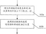
步骤103a:增大抖动缓存深度至新设置的J0,并设置新的抖动上下门限J1 和J2。
如果监测到的Jk大于原J1,说明PDV存在过大的情况。这样就需要增大抖动缓存。设置新的抖动缓存深度为J0,和抖动上下门限J1和J2。这些参数仍要求满足: If the monitored Jk is greater than the original J1, it indicates that the PDV is too large. This requires an increase in the jitter buffer. Set the new jitter buffer depth to J0, and the jitter upper and lower thresholds J1 and J2. These parameters are still required to be met:
J2<Jk<J1<J0 J2<Jk<J1<J0
J2=J0×20% J2=J0×20%
J1=J0×80% J1=J0×80%
Jk=J0×70% Jk=J0×70%
其中,除了第一个关系式以外,其它比例关系都是可以自由调整的,只要不与第一个关系式发生冲突即可,式中的20%、80%和70%只是本实施例中的一种选择值。Jk就是前三个时间段T内监测得到的写指针抖动范围的平均值;如果上个时间段T内Jk是原有J0的95%以上,而没有经过三个时间段的监测就直接调整,则Jk就直接取上个时间段T内写指针的Jk。 Wherein, except for the first relational expression, other proportional relations can be adjusted freely, as long as there is no conflict with the first relational expression, 20%, 80% and 70% in the formula are only the present embodiment. An option value. Jk is the average value of the write pointer jitter range monitored in the first three time periods T; if Jk in the last time period T is more than 95% of the original J0, and it is directly adjusted without monitoring in the three time periods, Then Jk directly takes the Jk of the write pointer in the last time period T. the
步骤103b:减缓读出数据的速率,将抖动缓存的写指针移动到新的抖动缓存深度J0的中心位置。
如果直接移动写指针至新的抖动缓存深度J0的中心位置,就容易使Jk立即小于新的J2而引起误判。所以选择通过减缓读出数据速率的方法,将抖动缓存的写指针移动到新的抖动缓存深度J0的中心位置,选择移动到中心位置的原因是为了防止写指针的抖动从缓存两端溢出。随着读出数据的速率的减缓,读写指针之间缓存的数据包增多,也就是说抖动缓存深度J0随之增大。减缓读出数据速率的操作由目的端控制实现。 If the write pointer is directly moved to the central position of the new jitter buffer depth J0, it is easy to make Jk immediately smaller than the new J2 and cause misjudgment. Therefore, the method of slowing down the read data rate is chosen to move the write pointer of the jitter buffer to the center of the new jitter buffer depth J0. The reason for choosing to move to the center is to prevent the jitter of the write pointer from overflowing from both ends of the buffer. As the rate of reading data slows down, the data packets buffered between the read and write pointers increase, that is to say, the jitter buffer depth J0 increases accordingly. The operation of slowing down the read data rate is controlled by the destination end. the
本子步骤中,由于减缓读出数据的速率,会造成所TDM业务定时质量的变化,例如在语音业务中,减缓读出数据的速率会导致输出语音频率变慢,而TDM业务中,对输出的时钟信息的变化率要求更加严格,所以移动抖动缓存的写指针的过程,应该确保读出数据速率的变化率满足所传输业务的指标要求。 In this sub-step, due to slowing down the speed of reading data, the change of the timing quality of the TDM service will be caused. For example, in the voice service, slowing down the speed of reading data will cause the output voice frequency to slow down, and in the TDM business, the frequency of the output voice will be slowed down. The change rate of the clock information is more stringent, so the process of moving the write pointer of the jitter buffer should ensure that the change rate of the read data rate meets the index requirements of the transmitted service. the
对于传输TDM数据帧而言,应该确保读出数据速率的变化率必须满足TDM业务定时指标的要求,该指标要求随实际应用场合而有所不同,例如:需 要满足G.823的业务口的指标要求,还是满足G.823的同步口的指标要求。由于以上原因,减缓读出数据的速率,将抖动缓存的写指针移动到新J0的中心位置的过程中,读出数据速率的变化率应被监控并实时调整,调整的依据则为所传输TDM业务的定时指标要求。 For the transmission of TDM data frames, it should be ensured that the rate of change of the read data rate must meet the requirements of the TDM service timing index, which varies with the actual application, for example: it needs to meet the requirements of the G.823 service port The index requirements still meet the index requirements of the synchronous port of G.823. Due to the above reasons, in the process of slowing down the read data rate and moving the write pointer of the jitter buffer to the center position of the new J0, the rate of change of the read data rate should be monitored and adjusted in real time. The adjustment is based on the transmitted TDM The timing index requirements of the business. the
步骤104:减小抖动缓存。 Step 104: Reduce the jitter buffer. the
如图5所示,减小抖动缓存包括两个子步骤: As shown in Figure 5, reducing the jitter buffer consists of two sub-steps:
步骤104a:设置新的抖动缓存深度J0,加快读出数据的速率,将抖动缓存的写指针移动到新的抖动缓存深度J0的中心位置。
与步骤103b中一致,为了避免对所传输业务的质量造成影响,本子步骤中首先根据监测到的Jk设置新的抖动缓存深度J0,并且,采用加快读出数据的速率的方法来将抖动缓存的写指针缓慢移动到新的抖动缓存深度J0的中心位置,与步骤103b中相同,加快读出数据速率的操作由目的端控制实现,读出数据速率的变化率应被监控并实时调整,调整的依据则为所传输TDM业务的定时指标要求。 Consistent with
其中,新的J0依然是靠关系式:Jk=J0×70%来得到,当然,该比例关系也可以选择其他数值,只要满足Jk<J0即可。其中Jk就是前三个时间段T监测得到的写指针移动范围的平均值。 Among them, the new J0 is still obtained by the relational formula: Jk=J0×70%. Of course, other values can be selected for this proportional relationship, as long as Jk<J0 is satisfied. Wherein Jk is the average value of the moving range of the write pointer obtained by monitoring the first three time periods T. the
步骤104b:设置新的抖动上下门限J1和J2。
根据新的抖动缓存深度J0,设置抖动上下门限J1和J2。这些参数仍要求满足: According to the new jitter buffer depth J0, set the jitter upper and lower thresholds J1 and J2. These parameters are still required to be met:
J2<Jk<J1<J0 J2<Jk<J1<J0
J2=J0×20% J2=J0×20%
J1=J0×80% J1=J0×80%
其中,除了第一个关系式以外,其它比例关系都是可以自由调整的,只要不与第一个关系式发生冲突即可,式中的20%和80%只是本实施例中的一种选择值,可以根据实际情况对其变更,例如选择30%,90%亦可。 Among them, except for the first relational expression, other proportional relations can be adjusted freely, as long as there is no conflict with the first relational expression, 20% and 80% in the formula are just a choice in this embodiment The value can be changed according to the actual situation, for example, 30% or 90% can be selected. the
为了使得本发明中的电路仿真系统的抖动缓存调整方法,能够随着网络的 PDV变化而自适应调整,步骤104之后还可以进一步包括步骤: In order to enable the jitter buffer adjustment method of the circuit emulation system in the present invention to be adaptively adjusted as the PDV of the network changes, steps may further be included after step 104:
继续反复执行步骤102和根据需要执行步骤103或104。 Continue to repeatedly execute step 102 and execute step 103 or 104 as needed. the
以上所述,仅为本发明的较佳实施例而已,并非用来限定本发明的保护范围。本领域内技术人员应该能够联想到,设置抖动缓存深度、抖动上下门限与写指针的抖动范围之间为其他的比例关系,设置不同的写指针移动速度和方式,调整不同长度的监测时间段,都应该属于本发明的保护范围。The above descriptions are only preferred embodiments of the present invention, and are not intended to limit the protection scope of the present invention. Those skilled in the art should be able to imagine that setting the depth of the jitter buffer, the upper and lower thresholds of jitter, and the jitter range of the write pointer are other proportional relationships, setting different moving speeds and modes of the write pointer, and adjusting monitoring time periods of different lengths. All should belong to the protection scope of the present invention.
Claims (8)
Translated fromChinesePriority Applications (1)
| Application Number | Priority Date | Filing Date | Title |
|---|---|---|---|
| CN2007101300145ACN101110661B (en) | 2007-07-23 | 2007-07-23 | Jitter Buffer Adjustment Method for Circuit Simulation System |
Applications Claiming Priority (1)
| Application Number | Priority Date | Filing Date | Title |
|---|---|---|---|
| CN2007101300145ACN101110661B (en) | 2007-07-23 | 2007-07-23 | Jitter Buffer Adjustment Method for Circuit Simulation System |
Publications (2)
| Publication Number | Publication Date |
|---|---|
| CN101110661A CN101110661A (en) | 2008-01-23 |
| CN101110661Btrue CN101110661B (en) | 2010-12-08 |
Family
ID=39042572
Family Applications (1)
| Application Number | Title | Priority Date | Filing Date |
|---|---|---|---|
| CN2007101300145AExpired - Fee RelatedCN101110661B (en) | 2007-07-23 | 2007-07-23 | Jitter Buffer Adjustment Method for Circuit Simulation System |
Country Status (1)
| Country | Link |
|---|---|
| CN (1) | CN101110661B (en) |
Families Citing this family (7)
| Publication number | Priority date | Publication date | Assignee | Title |
|---|---|---|---|---|
| CN102158402B (en)* | 2011-03-16 | 2013-10-02 | 华为技术有限公司 | Method and device for cache cells of xbar |
| CN102571561B (en)* | 2011-12-16 | 2014-08-06 | 瑞斯康达科技发展股份有限公司 | PWE3 device and method for reading and writing data in jitter buffer of device |
| CN103870248A (en)* | 2014-03-06 | 2014-06-18 | 北京神舟航天软件科技有限公司 | Dynamic self-adapting technique for simulating buffer zone of instruction set |
| CN106211306B (en) | 2015-04-30 | 2020-04-03 | 华为技术有限公司 | A communication network delay jitter smoothing method, device and system |
| CN110875860B (en)* | 2020-01-20 | 2020-07-10 | 翱捷科技(上海)有限公司 | Method and device for processing network jitter |
| CN114979091B (en)* | 2022-07-28 | 2022-11-11 | 腾讯科技(深圳)有限公司 | A data transmission method, related apparatus, equipment and storage medium |
| CN118041874B (en)* | 2024-01-10 | 2025-06-20 | 荣耀终端股份有限公司 | Data processing method and electronic device |
Citations (3)
| Publication number | Priority date | Publication date | Assignee | Title |
|---|---|---|---|---|
| US20030026275A1 (en)* | 2001-07-17 | 2003-02-06 | Christopher Lanzafame | Dynamic Jitter buffering for voice-over-IP and other packet-based communication systems |
| US20030112796A1 (en)* | 1999-09-20 | 2003-06-19 | Broadcom Corporation | Voice and data exchange over a packet based network with fax relay spoofing |
| CN1820517A (en)* | 2003-11-14 | 2006-08-16 | 中兴通讯股份有限公司 | Packet scheduling method of wireless communication system |
- 2007
- 2007-07-23CNCN2007101300145Apatent/CN101110661B/ennot_activeExpired - Fee Related
Patent Citations (3)
| Publication number | Priority date | Publication date | Assignee | Title |
|---|---|---|---|---|
| US20030112796A1 (en)* | 1999-09-20 | 2003-06-19 | Broadcom Corporation | Voice and data exchange over a packet based network with fax relay spoofing |
| US20030026275A1 (en)* | 2001-07-17 | 2003-02-06 | Christopher Lanzafame | Dynamic Jitter buffering for voice-over-IP and other packet-based communication systems |
| CN1820517A (en)* | 2003-11-14 | 2006-08-16 | 中兴通讯股份有限公司 | Packet scheduling method of wireless communication system |
Also Published As
| Publication number | Publication date |
|---|---|
| CN101110661A (en) | 2008-01-23 |
Similar Documents
| Publication | Publication Date | Title |
|---|---|---|
| CN101110661B (en) | Jitter Buffer Adjustment Method for Circuit Simulation System | |
| US7948974B2 (en) | Creating a low bandwidth channel within a high bandwidth packet stream | |
| US11785113B2 (en) | Client service transmission method and apparatus | |
| CN106162860B (en) | Time synchronization method and system, and network device | |
| US20080267073A1 (en) | Method and System for Ethernet Congestion Management | |
| CN101146091B (en) | Multi-channel data output method and system | |
| CN111095860B (en) | Method and device for clock synchronization | |
| CN104113517A (en) | Timestamp generation method, device and system | |
| JP5445271B2 (en) | BAND CONTROL DEVICE, BAND CONTROL METHOD, AND PROGRAM | |
| JP2022537187A (en) | Congestion control method and apparatus, communication network, and computer storage medium | |
| EP2630752B1 (en) | Layer one path delay compensation | |
| CN108282416A (en) | A kind of dispatching method and device based on data frame | |
| CN102571561B (en) | PWE3 device and method for reading and writing data in jitter buffer of device | |
| JP4652314B2 (en) | Ether OAM switch device | |
| EP1872596A1 (en) | Power reduction in switch architectures | |
| EP2278757B1 (en) | Flow control mechanism for data transmission links | |
| US9461925B1 (en) | Methods and apparatus for implementing dynamic rate controllers using linked list of rate programs | |
| Ma et al. | Demonstration of latency control label-based bounded-jitter scheduling in a bridged network for industrial Internet | |
| CN102984087B (en) | A kind of adaptive flow control method for storage extension of fibre channel | |
| CN102104909B (en) | Data processing method and device | |
| JP5750387B2 (en) | Frame control device, transmission device, network system, and buffer read control method | |
| US9237061B2 (en) | Transmission apparatus and transmission method | |
| US12438830B2 (en) | Providing high assurance of end-to-end CPRI circuit in a high jitter packet based fronthaul network | |
| CN103905322B (en) | A kind of method and apparatus for realizing data transfer via PTN | |
| JP2762803B2 (en) | Cell Flow Controller for Asynchronous Transfer Mode Transmission Network |
Legal Events
| Date | Code | Title | Description |
|---|---|---|---|
| C06 | Publication | ||
| PB01 | Publication | ||
| C10 | Entry into substantive examination | ||
| SE01 | Entry into force of request for substantive examination | ||
| C14 | Grant of patent or utility model | ||
| GR01 | Patent grant | ||
| CF01 | Termination of patent right due to non-payment of annual fee | Granted publication date:20101208 | |
| CF01 | Termination of patent right due to non-payment of annual fee |