CN101107712A - Protective circuit with current bypass for solar cell module - Google Patents
Protective circuit with current bypass for solar cell moduleDownload PDFInfo
- Publication number
- CN101107712A CN101107712ACN 200680003235CN200680003235ACN101107712ACN 101107712 ACN101107712 ACN 101107712ACN 200680003235CN200680003235CN 200680003235CN 200680003235 ACN200680003235 ACN 200680003235ACN 101107712 ACN101107712 ACN 101107712A
- Authority
- CN
- China
- Prior art keywords
- solar cell
- protective circuit
- circuit
- control circuit
- crested
- Prior art date
- Legal status (The legal status is an assumption and is not a legal conclusion. Google has not performed a legal analysis and makes no representation as to the accuracy of the status listed.)
- Pending
Links
Images


Classifications
- Y—GENERAL TAGGING OF NEW TECHNOLOGICAL DEVELOPMENTS; GENERAL TAGGING OF CROSS-SECTIONAL TECHNOLOGIES SPANNING OVER SEVERAL SECTIONS OF THE IPC; TECHNICAL SUBJECTS COVERED BY FORMER USPC CROSS-REFERENCE ART COLLECTIONS [XRACs] AND DIGESTS
- Y02—TECHNOLOGIES OR APPLICATIONS FOR MITIGATION OR ADAPTATION AGAINST CLIMATE CHANGE
- Y02E—REDUCTION OF GREENHOUSE GAS [GHG] EMISSIONS, RELATED TO ENERGY GENERATION, TRANSMISSION OR DISTRIBUTION
- Y02E10/00—Energy generation through renewable energy sources
- Y02E10/50—Photovoltaic [PV] energy
Landscapes
- Charge And Discharge Circuits For Batteries Or The Like (AREA)
Abstract
Description
The present invention relates to a kind of protective circuit; be used to be electrically connected to the solar cell of solar module; have a protection equipment, this protection equipment current bypass as the solar cell of this crested under the situation of the solar cell of crested works.
Be used to be electrically connected to this protective circuit on the solar cell of solar module, from practice with diversified expansion scheme by well-known.Sort circuit partly is also referred to as the connecting circuit into solar cell.
Generally a plurality of solar cells are connected into solar module.For this reason, in solar module or have the possibility of the series circuit of solar cell, or there is the possibility of parallel circuits.By the parallel connection of solar cell, each current summation of solar cell becomes a total current.Certainly, solar cell in parallel should have identical physical characteristic basically at this, make the parallel connection of solar cell almost not be implemented in practice, especially also because a single solar cell can provide some amperes electric current, and the output voltage of single solar cell is typically too little, so that can not move the electric equipment as household electrical appliance.
So when making up solar module by single solar cell, these solar cells of usually connecting.The partly crested but if solar module is in operation, be a solar cell of solar module or a plurality of solar cell less or even do not obtain solar radiation, then may have problems at this.The reason of the solar radiation of this minimizing for example may be the pollution of solar cell and/or the shade input of trees, building service or building itself.
With opposite to covering of solar module on its whole area equably, wherein said covering generally speaking only causes power reduction, produce following problem under the situation that part is covered: common electric current flows through the solar cell of the series connection of solar module, and wherein each single solar cell is made contributions to the total voltage of solar module with its correspondent voltage.If solar cell crested now, this solar cell formation voltage no longer then, and in fact be in by direction with diode and resist current flowing in the solar module.But this means that the whole solar cell module no longer can provide electric current, so that have influence on the whole functional of solar module.
What be suitable in addition is to apply the relevant voltage in the position of solar cell in series circuit with crested on the solar cell of crested.If be applied to described voltage on the solar cell of crested greater than its cut-ff voltage (Sperrspannng), then in solar cell, cause puncturing and therefore cause lasting damage.
If even by puncturing the damage that does not cause solar cell, loss power big in the solar cell of crested is converted, make the solar cell of crested give birth to heat.This heat of giving birth to also may cause to the solar cell of crested and to the damage of its adjacent solar cell.
The problem that is associated for fear of the solar cell with the part crested adopts and the antiparallel protection equipment of solar cell, general bypass diode just.Realize in this way,, still keep current flowing though the solar cell of crested no longer provides component to the total voltage of solar module.Therefore solar module shows the operating voltage that only reduces, but not exclusively loses efficacy.In addition, transfer power no longer in the solar cell of crested makes and can avoid damage to the solar cell of crested.
Distribute just what a bypass diode can in principle each solar cell of solar module.But carry out always the case, make respectively and to protect a plurality of solar cells that connect in succession, so-called solar cell string just by a common bypass diode.
Therefore, the protective circuit that is used to be electrically connected on the solar cell of solar module generally has at least one bypass diode, usually has a plurality of bypass diodes.But the problem that is associated therewith is, makes the protective circuit heating of the solar cell that is used to be electrically connected solar module greatly by the power of being changed in bypass diode, and this is disadvantageous aspect different.
Therefore task of the present invention is, this protective circuit on a kind of solar cell that is used to be electrically connected to solar module be described, and this protective circuit is in operation and only generates heat on a small quantity.
Described from the outset protective circuit is set out, and solves aforementioned task in the following manner, and promptly protective circuit has the controlled electronic switch device as protection equipment.
Therefore stipulate according to the present invention that the problems referred to above for fear of the solar cell with the part crested is associated are adopted as protection equipment with the controlled electronic switch device, the feasible use that can reduce or avoid fully bypass diode.By replacing bypass diode by the controlled electronic switch device, such minimizing that realizes the heating of switching device that can be as detailed below, wherein said controlled electronic switch device is identical with the bypass diode effect basically on function.
Can realize with different methods now with from this same function on function of bypass diode known in the art.To this, according to a kind of preferred improvement project regulation of the present invention, the controlled electronic switch device has control circuit and can be by the switchgear of control circuit control, wherein switchgear is parallel at least one solar cell, preferably is parallel to a string solar cell, and under the situation of a solar cell in parallel in covering solar cell with this switchgear by control circuit at least temporarily by biasing (aufsteuern), make to realize being used for the current bypass of the solar cell of crested.
Can realize corresponding switchgear in a different manner.Yet according to a kind of preferred improvement project regulation according to the present invention, switchgear have two series connection and by the switch element of the electric or electronics of control circuit control.A kind of preferred improvement project according to the present invention is especially stipulated at this, two transistors that polarize toward each other, preferred two MOSFET is set as switch element.What be suitable in addition is, according to a kind of preferred improvement project regulation of the present invention, carry out electric current supply by the electric current that solar cell generated to control circuit by the not crested of solar module, a kind of preferred improvement project wherein according to the present invention stipulates that especially control circuit is equipped with holding capacitor.
Alternately; according to a kind of preferred form of implementation regulation; the controlled electronic switch device is set as protection equipment; this controlled electronic switch device is for a string at least solar cell; have at least one transistor and at least one DC/DC transducer in parallel with it, this DC/DC transducer is connected with control circuit by accumulator.Particularly advantageously in this structure be, protection equipment has several cheap MOSFET that the low spatial demand is arranged, because generated from the small forward voltage of the parasitic diode of MOSFET by electric pressure converter it is controlled needed voltage.
In addition, if, then be particularly advantageous by realizing voltage transitions at least two string solar cells that protection equipment are integrated into solar module.Therefore possible on the one hand is that protection equipment is alternately powered the voltage on being present in MOSFET fully, because there are a plurality of MOSFET.On the other hand, when all belong to the solar cell crested of a string, can from the summation of the forward voltage of the parasitic diode of MOSFET, obtain enough voltage, so that this voltage is used for conversion and the control of MOSFET.In addition advantageously; the maximum voltage limit that every protection equipment is occurred on oppositely is the forward voltage of silicon diode, and this makes under the underexpose situation to the remaining solar cell that is in operation, the risk minimum of power supply complete failure under the diffused light situation for example.
At last; in all above-mentioned expansion scheme of the protective circuit of the used for solar batteries of solar module; according to a kind of preferred improvement project regulation according to the present invention, adopt a kind of over-voltage protection element to be used to prevent that protective circuit and solar cell from avoiding the overvoltage that for example causes by the thunderbolt (Blitzeinschlag) that is close to.
At length, the multiple possibility that has expansion and improvement protective circuit of the present invention now.Consult dependent claims and to the following detailed description of the preferred embodiment of the present invention for this reason.
Fig. 1 schematic presentation protective circuit according to a first advantageous embodiment of the invention,
Fig. 2 has showed the structure from the control circuit of Fig. 1 in detail,
Fig. 3 schematic presentation according to the protective circuit of second preferred embodiment,
Fig. 4 schematic presentation according to the protective circuit of the 3rd preferred embodiment,
Fig. 5 showed in detail from the structure of the DC/DC transducer of Fig. 3 or 4 and
Fig. 6 has showed the structure from the control circuit of Fig. 3 or 4 in detail.
Fig. 1 has showed thesolar cell 1 of thestring 2 with a plurality of series connection, and describedstring 2 is made up of a plurality of solar cells that be not shown specifically again, same series connection in its side.Forsolar module 1 threestrings 2 being set is exemplary purely.Equally exemplarily show by protection according to the protective circuit of a preferred embodiment of the present invention forstring 2 only.Certainly corresponding protection is set for each string.
As above set forth; target is that a kind of like this protective circuit is described; this protective circuit is guaranteed; under the situation of the string crested of being protected with it, realize the current bypass of the string of this crested; make thatsolar module 1 continues to keep operation to prepare, electric current promptly is provided on the one hand, and prevent the damage of thestring 2 of crested on the other hand.Protective circuit has controlled electronic switch device 3 for this reason, and this controlled electronic switch device 3 hascontrol circuit 4 andswitchgear 5.
By two can by the switch element ofcontrol circuit 4 control, promptly by two toward each other theMOSFET control circuit 4 is provided withholding capacitor 8, makes and under the situation ofstring 2 cresteds of protecting by protective circuit, realize following flow process:
When having covered the string protected 2 and continue theremaining string 2 of irradiationsolar module 1 since the parasitic diode oftop MOSFET 2 and below play on theMOSFET 7 of effect and set up a voltage.Present sodesign control circuit 4, make this control circuit by toMOSFET 7 at least partly biasing be about 20 V with this voltage limit, thereby avoid the damage of thestring 2 protected.In this stage, charge in the mode of current limited the voltage ofholding capacitor 8 from MOSFET 7.Incase holding capacitor 8 is charged to about 15 V, thenMOSFET MOSFET
Because self current drain ofcontrol circuit 4, on holdingcapacitor 8 and the voltage at the grid place ofMOSFET circuit 4 turn-offs MOSFET7 at least to the complete biased voltage ofMOSFET 6,7.So onMOSFET 7, set up the and for example restricted voltage of the above.MOSFET6,7 conducting phase continue a few tens of milliseconds.What very short voltage was limited owing to compare with conducting phase ends the stage, therefore play a decisive role hardly with respect to conduction loss at the instantaneous high loss power onMOSFET
Sodesign control circuit 4 in addition, make when shining not to this control circuit power supply, so thatMOSFET string 2 of being protected.Therefore, except MOSFET6,7 small cut-off current, any loss do not occur, make total losses actually even be lower than the loss of Schottky diode by controlled electronic switch device 3.In addition, in current described protective circuit according to a preferred embodiment of the invention, importantly, the limited controlled electric switchgear in the stage of voltage from remaining, promptly powered the feasible externally fed that do not need the alsoirradiated string 2.
Above-mentioned functional in order to realize,control circuit 4 has the Schmidt trigger by the drain electrode power supply ofMOSFET 7 basically.This Schmidt trigger is responsible for, and has only when being applied with voltage oncapacitor 8, just toMOSFET capacitor 8, switching device 3, draw pulse interval than (Puls-Pauseen-Verh ltnis).
Thereforecontrol circuit 4 totally shows as a kind of comparator circuit basically, and this comparator circuit also can be constructed as can be seen from Figure 2 in detail.This circuit is a kind of discrete equivalent electric circuit with aforesaid voltage watch-dog IC of same above-mentioned additional wiring basically.
Below explanation has the present invention second and the 3rd preferred embodiment of one or two DC/DC transducer.
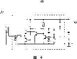
As from Fig. 3 and 4, drawing, solar module have usually a plurality of series connection string A, B ..., X, give described string at leastdispense switch device 100 as protection equipment.Obviously show string A, B at this, and only represent to go here and there X and should showing, the string more than can connecting arbitrarily in principle with point.Each string A-X is made up of the solar cell 1-n of a plurality of series connection.
As especially from Fig. 3, drawing; according to second preferred embodiment of the present invention; circuit arrangement hasMOSFET 10 and DC/DC transducer 20 as protection equipment for each string A-X, and this DC/DC transducer is connected withcontrol circuit 40 by accumulator 30.As described,MOSFET 10 is parallel to string A-X respectively, and is connected withcontrol circuit 40 by its grid.All string A-X are combined into a solar module and distribute to inverter UM.
As especially from Fig. 4, drawing, according to the 3rd preferred embodiment of the present invention, will go here and there respectively among the A-X two, promptly respectively two string A and B and C and D are distributed to a protection equipment jointly.Each solar battery group A and B or C and D haveMOSFET 10 in parallel.TwoMOSFET 10 are connected withcommon control circuit 40 respectively by its grid, wherein realize the power supply ofcontrol circuit 40 by per two DC/DC transducers 20 that distributed of giving string A-X, described DC/DC transducer 20 is parallel to the series circuit of string A-X, wherein gives adistribution accumulator 30 in the DC/DC transducer 20.Therefore possible on the one hand is that the common protection equipment of two usefulness among the string A-X is alternately powered the voltage on being present inMOSFET 10 sufficiently, because there are twoMOSFET 10 in each protection equipment.On the other hand, can be when having covered all strings that belong to a protection equipment from the summation of the forward voltage of the parasitic diode ofMOSFET 10, obtain enough voltage, so that this voltage is used for conversion and the control of MOSFET 10.Here also all string A-X are combined into a solar module and distribute to an inverter UM.
From Fig. 5 now as can be seen, the DC/DC transducer 20 of structural map 3 how in detail.The voltage transitions that will be produced on the internal body diodes ofMOSFET 10 when string A-X crested becomes to be applicable to the DC/DC transducer 20 of the voltage ofcontrol MOSFET 10, should be to be lower than the input voltage work of 0.7 V, so that guarantee bypass functionality.For example the Meissner oscillator of setting up withgermanium transistor 50 can be used for this purpose, and the converter of this Meissner oscillator contains the tertiary winding.Can consult the textbook " Halbleiter-Schaltungstechnik " (the 9th edition, the 461st page reaches page or leaf subsequently) of U.Tietze and Ch.Schenk about the Meissner oscillator.Via the tertiary winding and the unidirectional rectification of converter, can recently extract the enough big control ofMOSFET 10 usefulness by selecting conversion.Thesilicon diode 60 that inverse parallel is arranged in the Base-Emitter section oftransistor 50 is used for preventing thattransistor 50 from avoiding the reverse input voltage that is produced at the string A-X that is shone.
Under the simplest situation,control circuit 40 is made up of Schmidt trigger basically, this Schmidt trigger is applied to this voltage on the grid ofMOSFET 10 viacapacitor 30 when surpassing certain threshold voltage, and when not surpassing this threshold voltage grid is discharged by hysteresis institute specified value.Schmidt trigger is responsible for, and has only when the voltage that applies atcapacitor 30 places on the threshold voltage that is inMOSFET 10, and ability is toMOSFET 10 biasings.From the hysteresis of Schmidt trigger and with the electric capacity ofcapacitor 30 self current drain that be associated, entire circuit draw the pulse interval ratio.
Be similar to the above further describedcontrol circuit 4 among Fig. 1, in current described preferred embodiment of the present invention, can be especially simply with voltage monitor IC, for example the MAX6462 with the Maxim Integrated Products that has illustrated realizes Schmidt trigger.This external this be suitable for be, as also being applicable to aforementioned preferred embodiments of the present invention, especially by adopting logic level MOSFET to realize suitable Schmitt trigger circuit.The present example ofcontrol circuit 40 as can be seen in detail from Fig. 6, this control circuit are in fact corresponding to the discrete equivalent electric circuit of voltage monitor IC.
The result is; therefore the protective circuit of the used for solar batteries of solar module is provided by the present invention; described protective circuit can be used as the protective circuit with bypass diode equally without a doubt; but have significantly less loss power, make to ensure significantly higher electric current.
Claims (12)
1. protective circuit; be used to be electrically connected the solar cell of solar module (1); has protection equipment; described protection equipment works as the current bypass that is used for the solar cell of crested under the solar cell situation of crested; it is characterized in that; described protective circuit has controlled electronic switch device (3,100) as protection equipment.
2. press the protective circuit of claim 1; it is characterized in that described controlled electronic switch device (3,100) has control circuit (4; 40) and can be by described control circuit (4; 40) Kong Zhi switchgear (5,10), wherein said switchgear (5; 10) in parallel with at least one solar cell; and under the situation of this solar cell crested,, make the current bypass of the solar cell of realizing being used for crested by described control circuit (4,40) biasing at least temporarily.
3. by the protective circuit of claim 2, it is characterized in that, switchgear (5) have two series connection and by the switch element electric or electronics (6,7) of control circuit (4) control.
4. by the protective circuit of claim 3, it is characterized in that, be provided with two toward each other polarization transistors, preferably MOSFET is as switch element (6,7).
5. by the protective circuit of one of claim 2 to 4, it is characterized in that, by realize electric current supply by the electric current that solar cell generated of the not crested of solar module (1) to described control circuit (4).
6. by the protective circuit of one of claim 2 to 5, it is characterized in that, for described control circuit (4) is provided with holding capacitor (8).
7. press the protective circuit of claim 1 or 2; it is characterized in that; described protection equipment has at least one transistor (10) and at least one DC/DC transducer (20) in parallel with it, and this DC/DC transducer (20) is connected with control circuit (40) by accumulator (30).
8. by the protective circuit of claim 7, it is characterized in that, MOSFET is set as transistor (10).
9. press the protective circuit of claim 7 or 8; it is characterized in that; distribute a protection equipment jointly for a plurality of solar cell strings (A-X); this protection equipment has the transistor (10) of a parallel connection of every string (A-X), and described transistor (10) is connected with control circuit (40) respectively by its corresponding grid.
10. by the protective circuit of claim 9, it is characterized in that every string (A-X) is realized power supply to control circuit (40) by corresponding D C/DC transducer (20), wherein said DC/DC transducer (20) is parallel to the series circuit of string (A-X).
11. the protective circuit by claim 10 is characterized in that, gives at least one the distribution accumulator (30) in the described DC/DC transducer (20).
12. want one of 7 to 11 protective circuit by right, it is characterized in that the control circuit of electronic-circuit device (40) has microcontroller.
Applications Claiming Priority (4)
| Application Number | Priority Date | Filing Date | Title |
|---|---|---|---|
| DE102005003720 | 2005-01-26 | ||
| DE102005003720.8 | 2005-01-26 | ||
| DE102005012213.2 | 2005-03-15 | ||
| DE102005018463.4 | 2005-04-20 |
Publications (1)
| Publication Number | Publication Date |
|---|---|
| CN101107712Atrue CN101107712A (en) | 2008-01-16 |
Family
ID=39000620
Family Applications (1)
| Application Number | Title | Priority Date | Filing Date |
|---|---|---|---|
| CN 200680003235PendingCN101107712A (en) | 2005-01-26 | 2006-01-24 | Protective circuit with current bypass for solar cell module |
Country Status (1)
| Country | Link |
|---|---|
| CN (1) | CN101107712A (en) |
Cited By (60)
| Publication number | Priority date | Publication date | Assignee | Title |
|---|---|---|---|---|
| CN102163938A (en)* | 2010-01-29 | 2011-08-24 | 三垦电气株式会社 | Sunshine power generation device and sunshine power generation system |
| CN102569430A (en)* | 2012-01-12 | 2012-07-11 | 苏州清莲纳米环保科技有限公司 | Solar battery pack |
| CN102738281A (en)* | 2012-07-05 | 2012-10-17 | 谢可勋 | Solar battery module protection circuit, solar junction box and power generation system |
| CN103208916A (en)* | 2012-01-11 | 2013-07-17 | 太阳能安吉科技有限公司 | Photovoltaic Module |
| CN103227588A (en)* | 2012-01-30 | 2013-07-31 | 太阳能安吉科技有限公司 | Photovoltaic panel circuit |
| CN103400882A (en)* | 2013-08-18 | 2013-11-20 | 苏州快可光电科技有限公司 | Photovoltaic assembly junction box with electrical connection protection |
| CN103972864A (en)* | 2014-05-15 | 2014-08-06 | 电子科技大学 | Bypass circuit for solar cell |
| CN104009713A (en)* | 2014-05-26 | 2014-08-27 | 扬州虹扬科技发展有限公司 | Circuit device capable of automatically recognizing hot spot effect of photovoltaic cell panel assembly |
| CN105264733A (en)* | 2013-06-28 | 2016-01-20 | 艾思玛太阳能技术股份公司 | Circuit arrangement for inline voltage supply, use of such a circuit arrangement and device having such a circuit arrangement |
| US9362743B2 (en) | 2008-05-05 | 2016-06-07 | Solaredge Technologies Ltd. | Direct current power combiner |
| US9368964B2 (en) | 2006-12-06 | 2016-06-14 | Solaredge Technologies Ltd. | Distributed power system using direct current power sources |
| US9401599B2 (en) | 2010-12-09 | 2016-07-26 | Solaredge Technologies Ltd. | Disconnection of a string carrying direct current power |
| US9407161B2 (en) | 2007-12-05 | 2016-08-02 | Solaredge Technologies Ltd. | Parallel connected inverters |
| US9537445B2 (en) | 2008-12-04 | 2017-01-03 | Solaredge Technologies Ltd. | Testing of a photovoltaic panel |
| US9543889B2 (en) | 2006-12-06 | 2017-01-10 | Solaredge Technologies Ltd. | Distributed power harvesting systems using DC power sources |
| US9548619B2 (en) | 2013-03-14 | 2017-01-17 | Solaredge Technologies Ltd. | Method and apparatus for storing and depleting energy |
| US9590526B2 (en) | 2006-12-06 | 2017-03-07 | Solaredge Technologies Ltd. | Safety mechanisms, wake up and shutdown methods in distributed power installations |
| US9639106B2 (en) | 2012-03-05 | 2017-05-02 | Solaredge Technologies Ltd. | Direct current link circuit |
| US9647442B2 (en) | 2010-11-09 | 2017-05-09 | Solaredge Technologies Ltd. | Arc detection and prevention in a power generation system |
| CN106656033A (en)* | 2016-10-27 | 2017-05-10 | 上海电机学院 | Photovoltaic crystal plate online fault monitoring method |
| US9680304B2 (en) | 2006-12-06 | 2017-06-13 | Solaredge Technologies Ltd. | Method for distributed power harvesting using DC power sources |
| US9812984B2 (en) | 2012-01-30 | 2017-11-07 | Solaredge Technologies Ltd. | Maximizing power in a photovoltaic distributed power system |
| US9831824B2 (en) | 2007-12-05 | 2017-11-28 | SolareEdge Technologies Ltd. | Current sensing on a MOSFET |
| US9853538B2 (en) | 2007-12-04 | 2017-12-26 | Solaredge Technologies Ltd. | Distributed power harvesting systems using DC power sources |
| US9853565B2 (en) | 2012-01-30 | 2017-12-26 | Solaredge Technologies Ltd. | Maximized power in a photovoltaic distributed power system |
| US9866098B2 (en) | 2011-01-12 | 2018-01-09 | Solaredge Technologies Ltd. | Serially connected inverters |
| US9869701B2 (en) | 2009-05-26 | 2018-01-16 | Solaredge Technologies Ltd. | Theft detection and prevention in a power generation system |
| US9876430B2 (en) | 2008-03-24 | 2018-01-23 | Solaredge Technologies Ltd. | Zero voltage switching |
| CN107800376A (en)* | 2016-04-05 | 2018-03-13 | 太阳能安吉科技有限公司 | Safety switch for photovoltaic system |
| US9948233B2 (en) | 2006-12-06 | 2018-04-17 | Solaredge Technologies Ltd. | Distributed power harvesting systems using DC power sources |
| US9960731B2 (en) | 2006-12-06 | 2018-05-01 | Solaredge Technologies Ltd. | Pairing of components in a direct current distributed power generation system |
| US9966766B2 (en) | 2006-12-06 | 2018-05-08 | Solaredge Technologies Ltd. | Battery power delivery module |
| US10061957B2 (en) | 2016-03-03 | 2018-08-28 | Solaredge Technologies Ltd. | Methods for mapping power generation installations |
| US10116217B2 (en) | 2007-08-06 | 2018-10-30 | Solaredge Technologies Ltd. | Digital average input current control in power converter |
| US10184965B2 (en) | 2006-12-06 | 2019-01-22 | Solaredge Technologies Ltd. | Monitoring of distributed power harvesting systems using DC power sources |
| US10396662B2 (en) | 2011-09-12 | 2019-08-27 | Solaredge Technologies Ltd | Direct current link circuit |
| US10599113B2 (en) | 2016-03-03 | 2020-03-24 | Solaredge Technologies Ltd. | Apparatus and method for determining an order of power devices in power generation systems |
| US10651647B2 (en) | 2013-03-15 | 2020-05-12 | Solaredge Technologies Ltd. | Bypass mechanism |
| US10673222B2 (en) | 2010-11-09 | 2020-06-02 | Solaredge Technologies Ltd. | Arc detection and prevention in a power generation system |
| US10673229B2 (en) | 2010-11-09 | 2020-06-02 | Solaredge Technologies Ltd. | Arc detection and prevention in a power generation system |
| CN111969073A (en)* | 2020-08-13 | 2020-11-20 | 苏州萨弗瑞能源科技有限公司 | Semi-flexible solar module and manufacturing method thereof |
| US11018623B2 (en) | 2016-04-05 | 2021-05-25 | Solaredge Technologies Ltd. | Safety switch for photovoltaic systems |
| US11031861B2 (en) | 2006-12-06 | 2021-06-08 | Solaredge Technologies Ltd. | System and method for protection during inverter shutdown in distributed power installations |
| US11081608B2 (en) | 2016-03-03 | 2021-08-03 | Solaredge Technologies Ltd. | Apparatus and method for determining an order of power devices in power generation systems |
| US11177768B2 (en) | 2012-06-04 | 2021-11-16 | Solaredge Technologies Ltd. | Integrated photovoltaic panel circuitry |
| US11177663B2 (en) | 2016-04-05 | 2021-11-16 | Solaredge Technologies Ltd. | Chain of power devices |
| US11264947B2 (en) | 2007-12-05 | 2022-03-01 | Solaredge Technologies Ltd. | Testing of a photovoltaic panel |
| US11296650B2 (en) | 2006-12-06 | 2022-04-05 | Solaredge Technologies Ltd. | System and method for protection during inverter shutdown in distributed power installations |
| US11309832B2 (en) | 2006-12-06 | 2022-04-19 | Solaredge Technologies Ltd. | Distributed power harvesting systems using DC power sources |
| CN115191083A (en)* | 2020-01-27 | 2022-10-14 | 韩华Qcells有限公司 | Solar cell module and method for operating a solar cell module |
| US11569660B2 (en) | 2006-12-06 | 2023-01-31 | Solaredge Technologies Ltd. | Distributed power harvesting systems using DC power sources |
| US11569659B2 (en) | 2006-12-06 | 2023-01-31 | Solaredge Technologies Ltd. | Distributed power harvesting systems using DC power sources |
| US11687112B2 (en) | 2006-12-06 | 2023-06-27 | Solaredge Technologies Ltd. | Distributed power harvesting systems using DC power sources |
| US11728768B2 (en) | 2006-12-06 | 2023-08-15 | Solaredge Technologies Ltd. | Pairing of components in a direct current distributed power generation system |
| US11735910B2 (en) | 2006-12-06 | 2023-08-22 | Solaredge Technologies Ltd. | Distributed power system using direct current power sources |
| US11855231B2 (en) | 2006-12-06 | 2023-12-26 | Solaredge Technologies Ltd. | Distributed power harvesting systems using DC power sources |
| US11881814B2 (en) | 2005-12-05 | 2024-01-23 | Solaredge Technologies Ltd. | Testing of a photovoltaic panel |
| US11888387B2 (en) | 2006-12-06 | 2024-01-30 | Solaredge Technologies Ltd. | Safety mechanisms, wake up and shutdown methods in distributed power installations |
| US12057807B2 (en) | 2016-04-05 | 2024-08-06 | Solaredge Technologies Ltd. | Chain of power devices |
| US12418177B2 (en) | 2009-10-24 | 2025-09-16 | Solaredge Technologies Ltd. | Distributed power system using direct current power sources |
- 2006
- 2006-01-24CNCN 200680003235patent/CN101107712A/enactivePending
Cited By (154)
| Publication number | Priority date | Publication date | Assignee | Title |
|---|---|---|---|---|
| US11881814B2 (en) | 2005-12-05 | 2024-01-23 | Solaredge Technologies Ltd. | Testing of a photovoltaic panel |
| US11855231B2 (en) | 2006-12-06 | 2023-12-26 | Solaredge Technologies Ltd. | Distributed power harvesting systems using DC power sources |
| US9960731B2 (en) | 2006-12-06 | 2018-05-01 | Solaredge Technologies Ltd. | Pairing of components in a direct current distributed power generation system |
| US11183922B2 (en) | 2006-12-06 | 2021-11-23 | Solaredge Technologies Ltd. | Distributed power harvesting systems using DC power sources |
| US12388492B2 (en) | 2006-12-06 | 2025-08-12 | Solaredge Technologies Ltd. | Safety mechanisms, wake up and shutdown methods in distributed power installations |
| US12316274B2 (en) | 2006-12-06 | 2025-05-27 | Solaredge Technologies Ltd. | Pairing of components in a direct current distributed power generation system |
| US11063440B2 (en) | 2006-12-06 | 2021-07-13 | Solaredge Technologies Ltd. | Method for distributed power harvesting using DC power sources |
| US12281919B2 (en) | 2006-12-06 | 2025-04-22 | Solaredge Technologies Ltd. | Monitoring of distributed power harvesting systems using DC power sources |
| US12276997B2 (en) | 2006-12-06 | 2025-04-15 | Solaredge Technologies Ltd. | Distributed power harvesting systems using DC power sources |
| US12224706B2 (en) | 2006-12-06 | 2025-02-11 | Solaredge Technologies Ltd. | Pairing of components in a direct current distributed power generation system |
| US11043820B2 (en) | 2006-12-06 | 2021-06-22 | Solaredge Technologies Ltd. | Battery power delivery module |
| US11031861B2 (en) | 2006-12-06 | 2021-06-08 | Solaredge Technologies Ltd. | System and method for protection during inverter shutdown in distributed power installations |
| US9368964B2 (en) | 2006-12-06 | 2016-06-14 | Solaredge Technologies Ltd. | Distributed power system using direct current power sources |
| US12107417B2 (en) | 2006-12-06 | 2024-10-01 | Solaredge Technologies Ltd. | Distributed power harvesting systems using DC power sources |
| US11296650B2 (en) | 2006-12-06 | 2022-04-05 | Solaredge Technologies Ltd. | System and method for protection during inverter shutdown in distributed power installations |
| US11309832B2 (en) | 2006-12-06 | 2022-04-19 | Solaredge Technologies Ltd. | Distributed power harvesting systems using DC power sources |
| US9543889B2 (en) | 2006-12-06 | 2017-01-10 | Solaredge Technologies Ltd. | Distributed power harvesting systems using DC power sources |
| US12068599B2 (en) | 2006-12-06 | 2024-08-20 | Solaredge Technologies Ltd. | System and method for protection during inverter shutdown in distributed power installations |
| US9590526B2 (en) | 2006-12-06 | 2017-03-07 | Solaredge Technologies Ltd. | Safety mechanisms, wake up and shutdown methods in distributed power installations |
| US11476799B2 (en) | 2006-12-06 | 2022-10-18 | Solaredge Technologies Ltd. | Distributed power harvesting systems using DC power sources |
| US12046940B2 (en) | 2006-12-06 | 2024-07-23 | Solaredge Technologies Ltd. | Battery power control |
| US12032080B2 (en) | 2006-12-06 | 2024-07-09 | Solaredge Technologies Ltd. | Safety mechanisms, wake up and shutdown methods in distributed power installations |
| US12027970B2 (en) | 2006-12-06 | 2024-07-02 | Solaredge Technologies Ltd. | Safety mechanisms, wake up and shutdown methods in distributed power installations |
| US9680304B2 (en) | 2006-12-06 | 2017-06-13 | Solaredge Technologies Ltd. | Method for distributed power harvesting using DC power sources |
| US12027849B2 (en) | 2006-12-06 | 2024-07-02 | Solaredge Technologies Ltd. | Distributed power system using direct current power sources |
| US11961922B2 (en) | 2006-12-06 | 2024-04-16 | Solaredge Technologies Ltd. | Distributed power harvesting systems using DC power sources |
| US11962243B2 (en) | 2006-12-06 | 2024-04-16 | Solaredge Technologies Ltd. | Method for distributed power harvesting using DC power sources |
| US11569660B2 (en) | 2006-12-06 | 2023-01-31 | Solaredge Technologies Ltd. | Distributed power harvesting systems using DC power sources |
| US11569659B2 (en) | 2006-12-06 | 2023-01-31 | Solaredge Technologies Ltd. | Distributed power harvesting systems using DC power sources |
| US10673253B2 (en) | 2006-12-06 | 2020-06-02 | Solaredge Technologies Ltd. | Battery power delivery module |
| US9853490B2 (en) | 2006-12-06 | 2017-12-26 | Solaredge Technologies Ltd. | Distributed power system using direct current power sources |
| US11888387B2 (en) | 2006-12-06 | 2024-01-30 | Solaredge Technologies Ltd. | Safety mechanisms, wake up and shutdown methods in distributed power installations |
| US11575260B2 (en) | 2006-12-06 | 2023-02-07 | Solaredge Technologies Ltd. | Distributed power harvesting systems using DC power sources |
| US11575261B2 (en) | 2006-12-06 | 2023-02-07 | Solaredge Technologies Ltd. | Distributed power harvesting systems using DC power sources |
| US10637393B2 (en) | 2006-12-06 | 2020-04-28 | Solaredge Technologies Ltd. | Distributed power harvesting systems using DC power sources |
| US11735910B2 (en) | 2006-12-06 | 2023-08-22 | Solaredge Technologies Ltd. | Distributed power system using direct current power sources |
| US11728768B2 (en) | 2006-12-06 | 2023-08-15 | Solaredge Technologies Ltd. | Pairing of components in a direct current distributed power generation system |
| US9948233B2 (en) | 2006-12-06 | 2018-04-17 | Solaredge Technologies Ltd. | Distributed power harvesting systems using DC power sources |
| US11594881B2 (en) | 2006-12-06 | 2023-02-28 | Solaredge Technologies Ltd. | Distributed power harvesting systems using DC power sources |
| US9966766B2 (en) | 2006-12-06 | 2018-05-08 | Solaredge Technologies Ltd. | Battery power delivery module |
| US11594880B2 (en) | 2006-12-06 | 2023-02-28 | Solaredge Technologies Ltd. | Distributed power harvesting systems using DC power sources |
| US11594882B2 (en) | 2006-12-06 | 2023-02-28 | Solaredge Technologies Ltd. | Distributed power harvesting systems using DC power sources |
| US11687112B2 (en) | 2006-12-06 | 2023-06-27 | Solaredge Technologies Ltd. | Distributed power harvesting systems using DC power sources |
| US11682918B2 (en) | 2006-12-06 | 2023-06-20 | Solaredge Technologies Ltd. | Battery power delivery module |
| US10097007B2 (en) | 2006-12-06 | 2018-10-09 | Solaredge Technologies Ltd. | Method for distributed power harvesting using DC power sources |
| US10447150B2 (en) | 2006-12-06 | 2019-10-15 | Solaredge Technologies Ltd. | Distributed power harvesting systems using DC power sources |
| US10184965B2 (en) | 2006-12-06 | 2019-01-22 | Solaredge Technologies Ltd. | Monitoring of distributed power harvesting systems using DC power sources |
| US11658482B2 (en) | 2006-12-06 | 2023-05-23 | Solaredge Technologies Ltd. | Distributed power harvesting systems using DC power sources |
| US10230245B2 (en) | 2006-12-06 | 2019-03-12 | Solaredge Technologies Ltd | Battery power delivery module |
| US11598652B2 (en) | 2006-12-06 | 2023-03-07 | Solaredge Technologies Ltd. | Monitoring of distributed power harvesting systems using DC power sources |
| US10516336B2 (en) | 2007-08-06 | 2019-12-24 | Solaredge Technologies Ltd. | Digital average input current control in power converter |
| US10116217B2 (en) | 2007-08-06 | 2018-10-30 | Solaredge Technologies Ltd. | Digital average input current control in power converter |
| US11594968B2 (en) | 2007-08-06 | 2023-02-28 | Solaredge Technologies Ltd. | Digital average input current control in power converter |
| US9853538B2 (en) | 2007-12-04 | 2017-12-26 | Solaredge Technologies Ltd. | Distributed power harvesting systems using DC power sources |
| US11894806B2 (en) | 2007-12-05 | 2024-02-06 | Solaredge Technologies Ltd. | Testing of a photovoltaic panel |
| US10693415B2 (en) | 2007-12-05 | 2020-06-23 | Solaredge Technologies Ltd. | Testing of a photovoltaic panel |
| US9979280B2 (en) | 2007-12-05 | 2018-05-22 | Solaredge Technologies Ltd. | Parallel connected inverters |
| US11183923B2 (en) | 2007-12-05 | 2021-11-23 | Solaredge Technologies Ltd. | Parallel connected inverters |
| US11183969B2 (en) | 2007-12-05 | 2021-11-23 | Solaredge Technologies Ltd. | Testing of a photovoltaic panel |
| US10644589B2 (en) | 2007-12-05 | 2020-05-05 | Solaredge Technologies Ltd. | Parallel connected inverters |
| US11693080B2 (en) | 2007-12-05 | 2023-07-04 | Solaredge Technologies Ltd. | Parallel connected inverters |
| US11264947B2 (en) | 2007-12-05 | 2022-03-01 | Solaredge Technologies Ltd. | Testing of a photovoltaic panel |
| US9407161B2 (en) | 2007-12-05 | 2016-08-02 | Solaredge Technologies Ltd. | Parallel connected inverters |
| US12055647B2 (en) | 2007-12-05 | 2024-08-06 | Solaredge Technologies Ltd. | Parallel connected inverters |
| US9831824B2 (en) | 2007-12-05 | 2017-11-28 | SolareEdge Technologies Ltd. | Current sensing on a MOSFET |
| US9876430B2 (en) | 2008-03-24 | 2018-01-23 | Solaredge Technologies Ltd. | Zero voltage switching |
| US11424616B2 (en) | 2008-05-05 | 2022-08-23 | Solaredge Technologies Ltd. | Direct current power combiner |
| US10468878B2 (en) | 2008-05-05 | 2019-11-05 | Solaredge Technologies Ltd. | Direct current power combiner |
| US9362743B2 (en) | 2008-05-05 | 2016-06-07 | Solaredge Technologies Ltd. | Direct current power combiner |
| US12218498B2 (en) | 2008-05-05 | 2025-02-04 | Solaredge Technologies Ltd. | Direct current power combiner |
| US10461687B2 (en) | 2008-12-04 | 2019-10-29 | Solaredge Technologies Ltd. | Testing of a photovoltaic panel |
| US9537445B2 (en) | 2008-12-04 | 2017-01-03 | Solaredge Technologies Ltd. | Testing of a photovoltaic panel |
| US10969412B2 (en) | 2009-05-26 | 2021-04-06 | Solaredge Technologies Ltd. | Theft detection and prevention in a power generation system |
| US9869701B2 (en) | 2009-05-26 | 2018-01-16 | Solaredge Technologies Ltd. | Theft detection and prevention in a power generation system |
| US11867729B2 (en) | 2009-05-26 | 2024-01-09 | Solaredge Technologies Ltd. | Theft detection and prevention in a power generation system |
| US12306215B2 (en) | 2009-05-26 | 2025-05-20 | Solaredge Technologies Ltd. | Theft detection and prevention in a power generation system |
| US12418177B2 (en) | 2009-10-24 | 2025-09-16 | Solaredge Technologies Ltd. | Distributed power system using direct current power sources |
| CN102163938A (en)* | 2010-01-29 | 2011-08-24 | 三垦电气株式会社 | Sunshine power generation device and sunshine power generation system |
| CN102163938B (en)* | 2010-01-29 | 2013-11-27 | 三垦电气株式会社 | Sunshine power generation device and sunshine power generation system |
| TWI456866B (en)* | 2010-01-29 | 2014-10-11 | Sanken Electric Co Ltd | Solar power generation unit and solar power generation system |
| US11489330B2 (en) | 2010-11-09 | 2022-11-01 | Solaredge Technologies Ltd. | Arc detection and prevention in a power generation system |
| US9647442B2 (en) | 2010-11-09 | 2017-05-09 | Solaredge Technologies Ltd. | Arc detection and prevention in a power generation system |
| US11070051B2 (en) | 2010-11-09 | 2021-07-20 | Solaredge Technologies Ltd. | Arc detection and prevention in a power generation system |
| US10673222B2 (en) | 2010-11-09 | 2020-06-02 | Solaredge Technologies Ltd. | Arc detection and prevention in a power generation system |
| US10673229B2 (en) | 2010-11-09 | 2020-06-02 | Solaredge Technologies Ltd. | Arc detection and prevention in a power generation system |
| US12003215B2 (en) | 2010-11-09 | 2024-06-04 | Solaredge Technologies Ltd. | Arc detection and prevention in a power generation system |
| US11349432B2 (en) | 2010-11-09 | 2022-05-31 | Solaredge Technologies Ltd. | Arc detection and prevention in a power generation system |
| US12407158B2 (en) | 2010-11-09 | 2025-09-02 | Solaredge Technologies Ltd. | Arc detection and prevention in a power generation system |
| US10931228B2 (en) | 2010-11-09 | 2021-02-23 | Solaredge Technologies Ftd. | Arc detection and prevention in a power generation system |
| US12295184B2 (en) | 2010-12-09 | 2025-05-06 | Solaredge Technologies Ltd. | Disconnection of a string carrying direct current power |
| US9401599B2 (en) | 2010-12-09 | 2016-07-26 | Solaredge Technologies Ltd. | Disconnection of a string carrying direct current power |
| US11271394B2 (en) | 2010-12-09 | 2022-03-08 | Solaredge Technologies Ltd. | Disconnection of a string carrying direct current power |
| US11996488B2 (en) | 2010-12-09 | 2024-05-28 | Solaredge Technologies Ltd. | Disconnection of a string carrying direct current power |
| US9935458B2 (en) | 2010-12-09 | 2018-04-03 | Solaredge Technologies Ltd. | Disconnection of a string carrying direct current power |
| US11205946B2 (en) | 2011-01-12 | 2021-12-21 | Solaredge Technologies Ltd. | Serially connected inverters |
| US12218505B2 (en) | 2011-01-12 | 2025-02-04 | Solaredge Technologies Ltd. | Serially connected inverters |
| US9866098B2 (en) | 2011-01-12 | 2018-01-09 | Solaredge Technologies Ltd. | Serially connected inverters |
| US10666125B2 (en) | 2011-01-12 | 2020-05-26 | Solaredge Technologies Ltd. | Serially connected inverters |
| US10396662B2 (en) | 2011-09-12 | 2019-08-27 | Solaredge Technologies Ltd | Direct current link circuit |
| CN103208916B (en)* | 2012-01-11 | 2017-09-12 | 太阳能安吉科技有限公司 | Photovoltaic module |
| CN103208916A (en)* | 2012-01-11 | 2013-07-17 | 太阳能安吉科技有限公司 | Photovoltaic Module |
| US11979037B2 (en) | 2012-01-11 | 2024-05-07 | Solaredge Technologies Ltd. | Photovoltaic module |
| US10931119B2 (en) | 2012-01-11 | 2021-02-23 | Solaredge Technologies Ltd. | Photovoltaic module |
| CN102569430A (en)* | 2012-01-12 | 2012-07-11 | 苏州清莲纳米环保科技有限公司 | Solar battery pack |
| US12094306B2 (en) | 2012-01-30 | 2024-09-17 | Solaredge Technologies Ltd. | Photovoltaic panel circuitry |
| US11183968B2 (en) | 2012-01-30 | 2021-11-23 | Solaredge Technologies Ltd. | Photovoltaic panel circuitry |
| US10381977B2 (en) | 2012-01-30 | 2019-08-13 | Solaredge Technologies Ltd | Photovoltaic panel circuitry |
| US11620885B2 (en) | 2012-01-30 | 2023-04-04 | Solaredge Technologies Ltd. | Photovoltaic panel circuitry |
| US11929620B2 (en) | 2012-01-30 | 2024-03-12 | Solaredge Technologies Ltd. | Maximizing power in a photovoltaic distributed power system |
| US9853565B2 (en) | 2012-01-30 | 2017-12-26 | Solaredge Technologies Ltd. | Maximized power in a photovoltaic distributed power system |
| US10992238B2 (en) | 2012-01-30 | 2021-04-27 | Solaredge Technologies Ltd. | Maximizing power in a photovoltaic distributed power system |
| US10608553B2 (en) | 2012-01-30 | 2020-03-31 | Solaredge Technologies Ltd. | Maximizing power in a photovoltaic distributed power system |
| CN103227588B (en)* | 2012-01-30 | 2017-06-30 | 太阳能安吉科技有限公司 | Photovoltaic panel circuit |
| US9923516B2 (en) | 2012-01-30 | 2018-03-20 | Solaredge Technologies Ltd. | Photovoltaic panel circuitry |
| US12191668B2 (en) | 2012-01-30 | 2025-01-07 | Solaredge Technologies Ltd. | Maximizing power in a photovoltaic distributed power system |
| US9812984B2 (en) | 2012-01-30 | 2017-11-07 | Solaredge Technologies Ltd. | Maximizing power in a photovoltaic distributed power system |
| CN103227588A (en)* | 2012-01-30 | 2013-07-31 | 太阳能安吉科技有限公司 | Photovoltaic panel circuit |
| US10007288B2 (en) | 2012-03-05 | 2018-06-26 | Solaredge Technologies Ltd. | Direct current link circuit |
| US9639106B2 (en) | 2012-03-05 | 2017-05-02 | Solaredge Technologies Ltd. | Direct current link circuit |
| US11177768B2 (en) | 2012-06-04 | 2021-11-16 | Solaredge Technologies Ltd. | Integrated photovoltaic panel circuitry |
| US12218628B2 (en) | 2012-06-04 | 2025-02-04 | Solaredge Technologies Ltd. | Integrated photovoltaic panel circuitry |
| CN102738281A (en)* | 2012-07-05 | 2012-10-17 | 谢可勋 | Solar battery module protection circuit, solar junction box and power generation system |
| US12003107B2 (en) | 2013-03-14 | 2024-06-04 | Solaredge Technologies Ltd. | Method and apparatus for storing and depleting energy |
| US10778025B2 (en) | 2013-03-14 | 2020-09-15 | Solaredge Technologies Ltd. | Method and apparatus for storing and depleting energy |
| US12255457B2 (en) | 2013-03-14 | 2025-03-18 | Solaredge Technologies Ltd. | Method and apparatus for storing and depleting energy |
| US9548619B2 (en) | 2013-03-14 | 2017-01-17 | Solaredge Technologies Ltd. | Method and apparatus for storing and depleting energy |
| US10651647B2 (en) | 2013-03-15 | 2020-05-12 | Solaredge Technologies Ltd. | Bypass mechanism |
| US12132125B2 (en) | 2013-03-15 | 2024-10-29 | Solaredge Technologies Ltd. | Bypass mechanism |
| US11424617B2 (en) | 2013-03-15 | 2022-08-23 | Solaredge Technologies Ltd. | Bypass mechanism |
| CN105264733B (en)* | 2013-06-28 | 2018-08-28 | 艾思玛太阳能技术股份公司 | Circuit arrangement for inline voltage feed and use thereof, device with circuit arrangement |
| CN105264733A (en)* | 2013-06-28 | 2016-01-20 | 艾思玛太阳能技术股份公司 | Circuit arrangement for inline voltage supply, use of such a circuit arrangement and device having such a circuit arrangement |
| CN103400882A (en)* | 2013-08-18 | 2013-11-20 | 苏州快可光电科技有限公司 | Photovoltaic assembly junction box with electrical connection protection |
| CN103972864B (en)* | 2014-05-15 | 2017-03-15 | 电子科技大学 | A kind of bypass circuit for solaode |
| CN103972864A (en)* | 2014-05-15 | 2014-08-06 | 电子科技大学 | Bypass circuit for solar cell |
| CN104009713A (en)* | 2014-05-26 | 2014-08-27 | 扬州虹扬科技发展有限公司 | Circuit device capable of automatically recognizing hot spot effect of photovoltaic cell panel assembly |
| US11824131B2 (en) | 2016-03-03 | 2023-11-21 | Solaredge Technologies Ltd. | Apparatus and method for determining an order of power devices in power generation systems |
| US11538951B2 (en) | 2016-03-03 | 2022-12-27 | Solaredge Technologies Ltd. | Apparatus and method for determining an order of power devices in power generation systems |
| US10540530B2 (en) | 2016-03-03 | 2020-01-21 | Solaredge Technologies Ltd. | Methods for mapping power generation installations |
| US12224365B2 (en) | 2016-03-03 | 2025-02-11 | Solaredge Technologies Ltd. | Apparatus and method for determining an order of power devices in power generation systems |
| US10599113B2 (en) | 2016-03-03 | 2020-03-24 | Solaredge Technologies Ltd. | Apparatus and method for determining an order of power devices in power generation systems |
| US10061957B2 (en) | 2016-03-03 | 2018-08-28 | Solaredge Technologies Ltd. | Methods for mapping power generation installations |
| US11081608B2 (en) | 2016-03-03 | 2021-08-03 | Solaredge Technologies Ltd. | Apparatus and method for determining an order of power devices in power generation systems |
| US11870250B2 (en) | 2016-04-05 | 2024-01-09 | Solaredge Technologies Ltd. | Chain of power devices |
| US11018623B2 (en) | 2016-04-05 | 2021-05-25 | Solaredge Technologies Ltd. | Safety switch for photovoltaic systems |
| US11201476B2 (en) | 2016-04-05 | 2021-12-14 | Solaredge Technologies Ltd. | Photovoltaic power device and wiring |
| US12348182B2 (en) | 2016-04-05 | 2025-07-01 | Solaredge Technologies Ltd. | Safety switch for photovoltaic systems |
| US12057807B2 (en) | 2016-04-05 | 2024-08-06 | Solaredge Technologies Ltd. | Chain of power devices |
| CN107800376B (en)* | 2016-04-05 | 2021-08-17 | 太阳能安吉科技有限公司 | Safety switches for photovoltaic systems |
| CN107800376A (en)* | 2016-04-05 | 2018-03-13 | 太阳能安吉科技有限公司 | Safety switch for photovoltaic system |
| US11177663B2 (en) | 2016-04-05 | 2021-11-16 | Solaredge Technologies Ltd. | Chain of power devices |
| US10230310B2 (en) | 2016-04-05 | 2019-03-12 | Solaredge Technologies Ltd | Safety switch for photovoltaic systems |
| CN106656033A (en)* | 2016-10-27 | 2017-05-10 | 上海电机学院 | Photovoltaic crystal plate online fault monitoring method |
| CN115191083A (en)* | 2020-01-27 | 2022-10-14 | 韩华Qcells有限公司 | Solar cell module and method for operating a solar cell module |
| CN111969073A (en)* | 2020-08-13 | 2020-11-20 | 苏州萨弗瑞能源科技有限公司 | Semi-flexible solar module and manufacturing method thereof |
Similar Documents
| Publication | Publication Date | Title |
|---|---|---|
| CN101107712A (en) | Protective circuit with current bypass for solar cell module | |
| US7864497B2 (en) | Protective circuit | |
| JP6299028B2 (en) | Circuit and method for limiting the open circuit voltage of a photovoltaic string | |
| US9218013B2 (en) | Method and system for connecting solar cells or slices in a panel system | |
| CA2892330C (en) | Dc-dc high voltage converter | |
| CN201256290Y (en) | Protection circuit for suppressing surge current and preventing input voltage reverse connection | |
| CN102522882B (en) | Protection circuit of converter power component | |
| DE102019200112A1 (en) | Multi-stage buck converter with reverse charging capability | |
| US20190356227A1 (en) | I/o protected buck then boost or boost then buck converter, with interleaving option | |
| CN101277055A (en) | Switching unit and converter circuit using same for switching multiple voltage levels | |
| WO2012159811A2 (en) | Energy storage device, and system having an energy storage device | |
| KR20160146122A (en) | Bidirectional non-isolation dc-dc converter with improved in stability | |
| CN109193922A (en) | A kind of power supply circuit for preventing redundant power output from flowing backward | |
| US20150108844A1 (en) | Hybrid energy storage system | |
| CN101552451A (en) | Switch power supply cycle-by-cycle wave over-voltage protection circuit | |
| CN108736715A (en) | Buck DC-DC converter | |
| US11894771B2 (en) | Current control circuit | |
| CN101009470A (en) | A power circuit for the calculating device | |
| WO2018236493A1 (en) | BATTERY MANAGEMENT SYSTEM | |
| KR102399088B1 (en) | Buck Converter with Zero-Current-Switching | |
| KR101734215B1 (en) | Bidirectional non-isolation dc-dc converter with improved in stability | |
| CN108599563A (en) | A kind of buck DC-DC converter | |
| CN201854178U (en) | Practical overcurrent protecting circuit | |
| Jain et al. | Interleaved DC to DC buck converter for low power application | |
| WO2007051321A3 (en) | Voltage changer circuit for switching a multitude of turn-on voltage levels |
Legal Events
| Date | Code | Title | Description |
|---|---|---|---|
| C06 | Publication | ||
| PB01 | Publication | ||
| C10 | Entry into substantive examination | ||
| SE01 | Entry into force of request for substantive examination | ||
| ASS | Succession or assignment of patent right | Owner name:KANTHERS PELLSBAO CO. KG Free format text:FORMER OWNER: KANTHERS PELLSBAO CO. KG; APPLICANT Effective date:20080328 | |
| C41 | Transfer of patent application or patent right or utility model | ||
| TA01 | Transfer of patent application right | Effective date of registration:20080328 Address after:German schalksmuhle Applicant after:Guenther Spelsberg GmbH Address before:German schalksmuhle Applicant before:Gunther spelsburg limited liability company Co-applicant before:Guenther Spelsberg Gmbh & Co. Kg | |
| C02 | Deemed withdrawal of patent application after publication (patent law 2001) | ||
| WD01 | Invention patent application deemed withdrawn after publication | Open date:20080116 |