CN101107032B - Injection device with dose feedback mechanism tip - Google Patents
Injection device with dose feedback mechanism tipDownload PDFInfo
- Publication number
- CN101107032B CN101107032BCN2006800030975ACN200680003097ACN101107032BCN 101107032 BCN101107032 BCN 101107032BCN 2006800030975 ACN2006800030975 ACN 2006800030975ACN 200680003097 ACN200680003097 ACN 200680003097ACN 101107032 BCN101107032 BCN 101107032B
- Authority
- CN
- China
- Prior art keywords
- dosage
- injection
- injection device
- feedback signal
- dose
- Prior art date
- Legal status (The legal status is an assumption and is not a legal conclusion. Google has not performed a legal analysis and makes no representation as to the accuracy of the status listed.)
- Active
Links
Images


Classifications
- A—HUMAN NECESSITIES
- A61—MEDICAL OR VETERINARY SCIENCE; HYGIENE
- A61M—DEVICES FOR INTRODUCING MEDIA INTO, OR ONTO, THE BODY; DEVICES FOR TRANSDUCING BODY MEDIA OR FOR TAKING MEDIA FROM THE BODY; DEVICES FOR PRODUCING OR ENDING SLEEP OR STUPOR
- A61M5/00—Devices for bringing media into the body in a subcutaneous, intra-vascular or intramuscular way; Accessories therefor, e.g. filling or cleaning devices, arm-rests
- A61M5/178—Syringes
- A61M5/31—Details
- A61M5/315—Pistons; Piston-rods; Guiding, blocking or restricting the movement of the rod or piston; Appliances on the rod for facilitating dosing ; Dosing mechanisms
- A61M5/31565—Administration mechanisms, i.e. constructional features, modes of administering a dose
- A61M5/31566—Means improving security or handling thereof
- A61M5/3157—Means providing feedback signals when administration is completed
- A—HUMAN NECESSITIES
- A61—MEDICAL OR VETERINARY SCIENCE; HYGIENE
- A61M—DEVICES FOR INTRODUCING MEDIA INTO, OR ONTO, THE BODY; DEVICES FOR TRANSDUCING BODY MEDIA OR FOR TAKING MEDIA FROM THE BODY; DEVICES FOR PRODUCING OR ENDING SLEEP OR STUPOR
- A61M5/00—Devices for bringing media into the body in a subcutaneous, intra-vascular or intramuscular way; Accessories therefor, e.g. filling or cleaning devices, arm-rests
- A61M5/178—Syringes
- A61M5/20—Automatic syringes, e.g. with automatically actuated piston rod, with automatic needle injection, filling automatically
- A—HUMAN NECESSITIES
- A61—MEDICAL OR VETERINARY SCIENCE; HYGIENE
- A61M—DEVICES FOR INTRODUCING MEDIA INTO, OR ONTO, THE BODY; DEVICES FOR TRANSDUCING BODY MEDIA OR FOR TAKING MEDIA FROM THE BODY; DEVICES FOR PRODUCING OR ENDING SLEEP OR STUPOR
- A61M5/00—Devices for bringing media into the body in a subcutaneous, intra-vascular or intramuscular way; Accessories therefor, e.g. filling or cleaning devices, arm-rests
- A61M5/178—Syringes
- A61M5/24—Ampoule syringes, i.e. syringes with needle for use in combination with replaceable ampoules or carpules, e.g. automatic
- A—HUMAN NECESSITIES
- A61—MEDICAL OR VETERINARY SCIENCE; HYGIENE
- A61M—DEVICES FOR INTRODUCING MEDIA INTO, OR ONTO, THE BODY; DEVICES FOR TRANSDUCING BODY MEDIA OR FOR TAKING MEDIA FROM THE BODY; DEVICES FOR PRODUCING OR ENDING SLEEP OR STUPOR
- A61M5/00—Devices for bringing media into the body in a subcutaneous, intra-vascular or intramuscular way; Accessories therefor, e.g. filling or cleaning devices, arm-rests
- A61M5/178—Syringes
- A61M5/31—Details
- A61M5/315—Pistons; Piston-rods; Guiding, blocking or restricting the movement of the rod or piston; Appliances on the rod for facilitating dosing ; Dosing mechanisms
- A61M5/31533—Dosing mechanisms, i.e. setting a dose
- A61M5/31545—Setting modes for dosing
- A61M5/31548—Mechanically operated dose setting member
- A61M5/3155—Mechanically operated dose setting member by rotational movement of dose setting member, e.g. during setting or filling of a syringe
- A61M5/31551—Mechanically operated dose setting member by rotational movement of dose setting member, e.g. during setting or filling of a syringe including axial movement of dose setting member
- A—HUMAN NECESSITIES
- A61—MEDICAL OR VETERINARY SCIENCE; HYGIENE
- A61M—DEVICES FOR INTRODUCING MEDIA INTO, OR ONTO, THE BODY; DEVICES FOR TRANSDUCING BODY MEDIA OR FOR TAKING MEDIA FROM THE BODY; DEVICES FOR PRODUCING OR ENDING SLEEP OR STUPOR
- A61M2205/00—General characteristics of the apparatus
- A61M2205/58—Means for facilitating use, e.g. by people with impaired vision
- A61M2205/581—Means for facilitating use, e.g. by people with impaired vision by audible feedback
- A—HUMAN NECESSITIES
- A61—MEDICAL OR VETERINARY SCIENCE; HYGIENE
- A61M—DEVICES FOR INTRODUCING MEDIA INTO, OR ONTO, THE BODY; DEVICES FOR TRANSDUCING BODY MEDIA OR FOR TAKING MEDIA FROM THE BODY; DEVICES FOR PRODUCING OR ENDING SLEEP OR STUPOR
- A61M2205/00—General characteristics of the apparatus
- A61M2205/58—Means for facilitating use, e.g. by people with impaired vision
- A61M2205/582—Means for facilitating use, e.g. by people with impaired vision by tactile feedback
- A—HUMAN NECESSITIES
- A61—MEDICAL OR VETERINARY SCIENCE; HYGIENE
- A61M—DEVICES FOR INTRODUCING MEDIA INTO, OR ONTO, THE BODY; DEVICES FOR TRANSDUCING BODY MEDIA OR FOR TAKING MEDIA FROM THE BODY; DEVICES FOR PRODUCING OR ENDING SLEEP OR STUPOR
- A61M5/00—Devices for bringing media into the body in a subcutaneous, intra-vascular or intramuscular way; Accessories therefor, e.g. filling or cleaning devices, arm-rests
- A61M5/178—Syringes
- A61M5/31—Details
- A61M5/315—Pistons; Piston-rods; Guiding, blocking or restricting the movement of the rod or piston; Appliances on the rod for facilitating dosing ; Dosing mechanisms
- A61M5/31533—Dosing mechanisms, i.e. setting a dose
- A61M5/31535—Means improving security or handling thereof, e.g. blocking means, means preventing insufficient dosing, means allowing correction of overset dose
- A—HUMAN NECESSITIES
- A61—MEDICAL OR VETERINARY SCIENCE; HYGIENE
- A61M—DEVICES FOR INTRODUCING MEDIA INTO, OR ONTO, THE BODY; DEVICES FOR TRANSDUCING BODY MEDIA OR FOR TAKING MEDIA FROM THE BODY; DEVICES FOR PRODUCING OR ENDING SLEEP OR STUPOR
- A61M5/00—Devices for bringing media into the body in a subcutaneous, intra-vascular or intramuscular way; Accessories therefor, e.g. filling or cleaning devices, arm-rests
- A61M5/178—Syringes
- A61M5/31—Details
- A61M5/315—Pistons; Piston-rods; Guiding, blocking or restricting the movement of the rod or piston; Appliances on the rod for facilitating dosing ; Dosing mechanisms
- A61M5/31533—Dosing mechanisms, i.e. setting a dose
- A61M5/31545—Setting modes for dosing
- A61M5/31548—Mechanically operated dose setting member
- A61M5/31561—Mechanically operated dose setting member using freely adjustable volume steps
- A—HUMAN NECESSITIES
- A61—MEDICAL OR VETERINARY SCIENCE; HYGIENE
- A61M—DEVICES FOR INTRODUCING MEDIA INTO, OR ONTO, THE BODY; DEVICES FOR TRANSDUCING BODY MEDIA OR FOR TAKING MEDIA FROM THE BODY; DEVICES FOR PRODUCING OR ENDING SLEEP OR STUPOR
- A61M5/00—Devices for bringing media into the body in a subcutaneous, intra-vascular or intramuscular way; Accessories therefor, e.g. filling or cleaning devices, arm-rests
- A61M5/178—Syringes
- A61M5/31—Details
- A61M5/315—Pistons; Piston-rods; Guiding, blocking or restricting the movement of the rod or piston; Appliances on the rod for facilitating dosing ; Dosing mechanisms
- A61M5/31565—Administration mechanisms, i.e. constructional features, modes of administering a dose
- A61M5/31576—Constructional features or modes of drive mechanisms for piston rods
- A61M5/31583—Constructional features or modes of drive mechanisms for piston rods based on rotational translation, i.e. movement of piston rod is caused by relative rotation between the user activated actuator and the piston rod
- A61M5/31585—Constructional features or modes of drive mechanisms for piston rods based on rotational translation, i.e. movement of piston rod is caused by relative rotation between the user activated actuator and the piston rod performed by axially moving actuator, e.g. an injection button
Landscapes
- Health & Medical Sciences (AREA)
- Vascular Medicine (AREA)
- Engineering & Computer Science (AREA)
- Anesthesiology (AREA)
- Biomedical Technology (AREA)
- Heart & Thoracic Surgery (AREA)
- Hematology (AREA)
- Life Sciences & Earth Sciences (AREA)
- Animal Behavior & Ethology (AREA)
- General Health & Medical Sciences (AREA)
- Public Health (AREA)
- Veterinary Medicine (AREA)
- Infusion, Injection, And Reservoir Apparatuses (AREA)
Abstract
Description
Translated fromChinese技术领域technical field
本发明涉及一种向哺乳动物(优选地人类)优选地以皮下方式输送液体药物的装置。更具体地,本发明涉及一种注射装置,它能够向用户提供非视觉反馈信号指示设定的剂量已经被注射装置注射。The present invention relates to a device for delivering liquid medicine, preferably subcutaneously, to a mammal, preferably a human. More particularly, the present invention relates to an injection device capable of providing a non-visual feedback signal to the user indicating that a set dose has been injected by the injection device.
背景技术Background technique
在本公开说明书中主要阐述通过注射胰岛素治疗糖尿病。但是,这仅仅是本发明的示范性应用。因此,本发明可用于注射任意其他适合类型的药物,例如生长激素。In this disclosure, the treatment of diabetes by insulin injection is mainly described. However, this is only an exemplary application of the present invention. Thus, the present invention can be used to inject any other suitable type of drug, such as growth hormone.
例如注射笔形式的注射装置主要用于那些必须经常自己注射的用户,例如,胰岛素依赖型糖尿病或需要用生长激素治疗的人。对这样的注射装置规定许多要求。剂量的设定必须容易且明确和其必须易于读出设定的剂量。而且,必须可以以最小的力气来取消或改变错误剂量设定。最后,当剂量被注射后剂量设定机构必须规零。这是非常重要的,因为其确保了设定剂量被确实地注射,由此允许用户明了注射了多少剂量。Injection devices, for example in the form of injection pens, are mainly used by users who have to inject themselves frequently, for example, people with insulin-dependent diabetes or who need to be treated with growth hormone. A number of requirements are imposed on such injection devices. The setting of the dose must be easy and unambiguous and it must be easy to read the set dose. Furthermore, it must be possible to cancel or change the wrong dose setting with minimal effort. Finally, the dose setting mechanism must be zeroed when the dose has been injected. This is very important as it ensures that the set dose is actually injected, thus allowing the user to keep track of how many doses have been injected.
许多注射装置采用螺纹活塞杆,该杆与螺母协同,螺母和活塞能够相对彼此旋转。可通过把螺母拨转到远离停止件而获得剂量设定,该停止件是注射过程中通过或者手工地或者借助例如弹簧的机械偏压机构向前按压活塞杆而使螺母返回的位置,直至螺母部件邻接停止件。在另一种注射装置中,部件中的一个,螺母或活塞杆,在允许另一个部件根据设定的剂量旋转规定角度时保持不旋转,由此沿向前的方向拨转活塞杆一个距离穿过螺母部件。Many injection devices employ a threaded piston rod which cooperates with a nut, the nut and piston being able to rotate relative to each other. Dose setting can be achieved by turning the nut away from the stop, which is the position at which the nut is returned during an injection by pressing the piston rod forward, either manually or by means of a mechanical biasing mechanism such as a spring, until the nut The part abuts the stop. In another type of injection device, one of the parts, the nut or the piston rod, is held non-rotating while allowing the other part to rotate by a specified angle in accordance with the set dose, thereby dialing the piston rod a distance in the forward direction. through the nut part.
在这种现有技术的注射装置中通常利用拨转剂量设定部件来设定剂量,和通过推动注射按钮注射设定剂量。在延长的笔形注射装置中剂量设定部件和注射按钮通常构成单个部件。当推动注射按钮时排出设定剂量。但是,如果尽可能远地推动注射按钮,药物排出的量仅仅等于设定剂量,剂量设定部件由此已经回到零。为了确保确实地注射正确的剂量,用户因此在注射过程中必须视觉地检查剂量设定部件的位置。这是不利的,因为在一些情况中注射会发生在身体的局部内,在那里注射期间的视觉检查是非常困难或甚至不可能的。而且,万一用户视力不好,不管在身体上的哪个位置上实施注射,可能使用户在注射期间或之后视觉地检查剂量设定部件变得困难。因为对于患有糖尿病的人来说视觉减弱不是罕见的,这是重要的方面。In such prior art injection devices, the dose is usually set by dialing the dose setting member, and the set dose is injected by pushing the injection button. In elongated pen-shaped injection devices the dose setting member and the injection button usually form a single part. The set dose is expelled when the injection button is pushed. However, if the injection button is pushed as far as possible, the amount of drug expelled is only equal to the set dose, whereby the dose setting member has returned to zero. To ensure that the correct dose is indeed injected, the user must therefore visually check the position of the dose setting member during the injection. This is disadvantageous because in some cases the injection may take place in a localized part of the body where visual inspection during the injection is very difficult or even impossible. Also, in case the user has poor eyesight, it may make it difficult for the user to visually check the dose setting member during or after the injection, no matter where on the body the injection is administered. Since it is not uncommon for people with diabetes to have diminished vision, this is an important aspect.
因此需要向用户提供一种反馈信号来指示设定剂量已经注射了,反馈信号是一种使用户不需视觉地检查是否已经注射了设定剂量。It is therefore desirable to provide a feedback signal to the user indicating that the set dose has been injected, a feedback signal which enables the user to check without visual inspection whether the set dose has been injected.
一些现有技术的注射装置具有通过针对每个已经注射的剂量单元产生声音“嘀哒”的方式通知用户已经注射了剂量的机构。但是,因为在整个注射过程中这些嘀哒声似乎不提供反馈信号指示已经注射了设定的剂量,因此通过这些注射装置没有解决上述问题。这种现有技术的注射装置例如US4,592,745,EP0688571和US2004/0210199中描述的。Some prior art injection devices have mechanisms to notify the user that a dose has been injected by producing an audible "tick" for each dose unit injected. However, the above-mentioned problems are not solved by these injection devices since these clicking sounds do not seem to provide a feedback signal throughout the injection process to indicate that the set dose has been injected. Such prior art injection devices are for example described in US4,592,745, EP0688571 and US2004/0210199.
在WO98/57688中,公开了一种解决上述问题的注射装置。因此,WO98/57688公开了一种具有剂量设定装置的注射装置。通过拨转剂量设定部件设定剂量。除了设定剂量,拨转动作还使注射按钮从邻接注射装置的壳体的位置移到从壳体突出的位置。设定剂量随后通过推动注射按钮返回进入与壳体邻接而被输送。在一个实施例中当注射按钮到达壳体时启动锁定,锁定的启动产生嘀哒声指示注射按钮与壳体邻接和由此已经输送了设定的剂量。在注射过程中,包括当启动锁定时的最后部分,注射按钮是线性移动的。在最后一些剂量的过程中注射按钮的线性行程相对短。因此其难于从锁定产生的嘀哒声精确判断是否以及何时已经输送了设定剂量。In WO98/57688 an injection device is disclosed which solves the above problems. Thus, WO98/57688 discloses an injection device with dose setting means. The dose is set by turning the dose setting part. In addition to setting the dose, the dial action also moves the injection button from a position adjacent to the housing of the injection device to a position protruding from the housing. The set dose is then delivered by pushing the injection button back into abutment with the housing. In one embodiment the lock is activated when the injection button reaches the housing, actuation of the lock producing an audible click indicating that the injection button abuts the housing and thus the set dose has been delivered. During the injection process, including the final part when the lock is activated, the injection button is moved linearly. The linear travel of the injection button is relatively short during the last few doses. It is therefore difficult to tell precisely from the clicking sound produced by the lock if and when the set dose has been delivered.
EP0594357公开了另一种解决上述问题的注射装置。如此,EP0594357公开了一种具有顶部段的注射装置,该顶部段具有从顶部段垂直下垂的有回弹力的腿。弹力腿的外表面有位于剂量按钮内侧的突出部分上的脊。剂量按钮具有适合圆柱套管的延长段以便当把剂量按钮推进套管时,在注射的末期,套管的顶部接触弹力腿的腿末端从突出部分移开脊并产生劈啪声。正如WO98/57688中描述的注射装置,在注射过程中和在注射的最后部分的过程中当弹力腿从脊移开产生劈啪声时线性地移动剂量按钮。因此可知道上述缺陷在此也适用。EP0594357 discloses another injection device which solves the above problems. Thus, EP0594357 discloses an injection device having a top section with resilient legs depending vertically from the top section. The outer surface of the spring leg has a ridge on the protrusion on the inside of the dose button. The dose button has an extension that fits into the cylindrical sleeve so that when the dose button is pushed into the sleeve, at the end of the injection, the top of the sleeve contacts the leg end of the spring leg to move away from the protrusion and snap. As with the injection device described in WO98/57688, the dose button is moved linearly during the injection and during the final part of the injection as the spring leg moves away from the spine creating a snap. It can thus be seen that the aforementioned disadvantages also apply here.
发明内容Contents of the invention
因此,本发明的一个目的是提供一种能够精确地并且以非视觉方式向用户指示何时设定剂量已经被注射的注射装置。It is therefore an object of the present invention to provide an injection device which is able to indicate to the user precisely and in a non-visual manner when a set dose has been injected.
本发明的另一个目的是提供一种能够非视觉地向用户指示何时设定剂量已经被注射的注射装置,以非常明显的方式向用户传递该指示。Another object of the present invention is to provide an injection device capable of non-visually indicating to the user when a set dose has been injected, conveying this indication to the user in a very obvious manner.
本发明的更进一步的目的是为注射装置提供剂量输送机构,剂量输送机构能够精确地并且以非视觉方式向用户指示何时设定剂量已经被注射。It is a still further object of the present invention to provide an injection device with a dose delivery mechanism capable of precisely and non-visually indicating to the user when a set dose has been injected.
根据本发明,上述及其他目的通过提供一种注射装置实现,包括:According to the present invention, the above and other objects are achieved by providing an injection device, comprising:
壳体,case,
剂量设定部件,可操作地设定需要注射的剂量,a dose setting part, operable to set the dose to be injected,
活塞杆,适于与活塞协同从而使设定剂量被从安瓿注射,和a piston rod adapted to cooperate with the piston so that the set dose is injected from the ampoule, and
剂量输送机构,适于以注射设定剂量的方式操作活塞杆,剂量输送机构进一步适于仅在注射设定剂量的末期向用户提供非视觉反馈信号,a dose delivery mechanism adapted to operate the piston rod to inject a set dose, the dose delivery mechanism being further adapted to provide a non-visual feedback signal to the user only at the end of the injection of the set dose,
其中注射装置的第一和第二部分适于在剂量注射期间相对彼此进行相对旋转运动,和其中所示相对旋转运动使注射装置的至少两个部分邻接或接合,所述邻接或接合使得产生非视觉反馈信号。wherein the first and second parts of the injection device are adapted to perform relative rotational movement relative to each other during dose injection, and wherein said relative rotational movement abuts or engages at least two parts of the injection device such that non- Visual feedback signal.
本发明的注射装置非常适于必须经常自己注射的人使用,例如,患有胰岛素依赖型糖尿病或需要用生长激素治疗的人。这样,通过剂量设定部件设定的期望剂量为一剂所谈论的人需要在特定地点及时注射的特定药。期望的剂量可以是患者需要每次注射的固定剂量,或者可以是变化数量,例如,根据时间和/或在设定剂量前测量或选择的一个或更多参数(例如血糖(BG)水平、食物的内容等)变化。The injection device of the present invention is very suitable for use by persons who must frequently self-inject, for example, persons suffering from insulin-dependent diabetes mellitus or requiring treatment with growth hormone. In this way, the desired dose set by the dose setting means is a dose of the specific drug that the person in question needs to be injected in time at a specific location. The desired dose may be a fixed dose that the patient requires per injection, or may be a variable amount, e.g., based on time and/or one or more parameters measured or selected prior to setting the dose (e.g., blood glucose (BG) level, food content, etc.) changes.
活塞杆优选地适于推动活塞进入安瓿,由此使设定剂量被注射。这可以通过各种方法获得并且是本领域公知和详细描述的。The piston rod is preferably adapted to push the piston into the ampoule, thereby causing the set dose to be injected. This can be obtained by various methods and is well known and well described in the art.
剂量输送机构适于仅在注射设定剂量的末期向用户提供非视觉反馈信号。因此,当已经注射了设定剂量时产生反馈信号,例如精确地在最后单位已经被注射时或者在最后单位刚被注射之后。或者,反馈信号在全部剂量已经被输送之前产生,例如当还剩很少的单位要注射时,剩下的单位在注射的同时用户可感觉到反馈信号。这样,当用户感知到反馈信号时设定剂量将已经被输送,并且用户因此不能说出在剂量已经被全部地注射之后产生的反馈信号与剂量已经被全部地注射之前的瞬间产生的反馈信号之间的区别。在任何时候用户可以认为对反馈信号的感知是设定剂量已经被输送的指示,用户可因此相应地作出反应,例如通过移开手工施加在注射按钮的压力。The dose delivery mechanism is adapted to provide a non-visual feedback signal to the user only at the end of injection of a set dose. Thus, the feedback signal is generated when the set dose has been injected, eg precisely when the last unit has been injected or just after the last unit has been injected. Alternatively, the feedback signal is generated before the full dose has been delivered, eg when few units remain to be injected, the remaining units being injected while the user feels the feedback signal. In this way, the set dose will have been delivered when the user perceives the feedback signal, and the user therefore cannot tell the difference between the feedback signal generated after the dose has been fully injected and the feedback signal generated immediately before the dose has been fully injected. difference between. At any time the user may regard the perception of the feedback signal as an indication that the set dose has been delivered and the user may therefore react accordingly, for example by removing manually applied pressure on the injection button.
由于非视觉反馈信号仅在设定剂量的注射末期提供,用户将明显地知道何时接收到设定剂量已经充分地注射的反馈信号。这与现有技术的注射装置针对每次注射的剂量单位而产生的嘀哒声相比较是有利的。在这种情况中,用户必须计算产生的嘀哒声的数量并将其与设定剂量单位的数量相比从而确切地断定何时设定剂量已经被充分地注射。Since the non-visual feedback signal is only provided at the end of the injection of the set dose, the user will clearly know when the feedback signal is received that the set dose has been sufficiently injected. This compares favorably with the clicking sound produced by prior art injection devices for each injected dosage unit. In this case, the user must count the number of clicks produced and compare this to the number of set dose units to determine exactly when the set dose has been sufficiently injected.
注射装置的第一部分和第二部分适于在剂量注射期间相对彼此进行相对旋转运动。这可以,例如,是壳体和活塞杆,或可以是分离部分和注射装置的任意其他部分,例如壳体和/或活塞杆,分离部件的唯一目的是产生非视觉反馈信号。注射装置的三个或更多部分可在剂量注射期间进行相互旋转运动。而且,相对旋转运动可在整个剂量注射过程中进行或仅在注射的部分中进行。这样,相对旋转运动可开始或停止在上述的设定剂量注射末期,在该情况中这种开始或停止可有利地使得产生非视觉反馈信号。The first part and the second part of the injection device are adapted for relative rotational movement relative to each other during dose injection. This could, for example, be the housing and piston rod, or could be a separate part and any other part of the injection device, such as the housing and/or the piston rod, the sole purpose of which is to generate a non-visual feedback signal. Three or more parts of the injection device may perform a mutual rotational movement during dose injection. Furthermore, the relative rotational movement can be performed during the entire dose injection or only during the injected part. In this way, the relative rotational movement may be started or stopped at the end of the above-mentioned set dose injection, in which case such starting or stopping may advantageously result in a non-visual feedback signal.
相对旋转运动使注射装置的至少两部分邻接或接合,并且这种邻接或接合使得产生非视觉反馈信号。邻接或接合的一个或两个部分可以是第一和/或第二部分,即,进行相对旋转运动的部分。或者,邻接或接合的一个或两个部分可以是注射装置的其他部分。这将在下面进一步详细说明。The relative rotational movement abuts or engages at least two parts of the injection device, and such abutment or engagement causes a non-visual feedback signal. The one or two parts that abut or join may be the first and/or the second part, ie the parts that undergo relative rotational movement. Alternatively, one or both parts that adjoin or join may be other parts of the injection device. This will be explained in further detail below.
由于相对旋转运动启动非视觉反馈信号的产生的事实,可以确定的是产生非视觉反馈信号的移动比相应的在注射装置内由一个或更多部件的线性移动产生反馈信号的移动长很多。由此产生的信号将更加精确和明显,并且由此提供了更加精确的反馈信号。这是非常有利的,因为这使用户更易于确定希望和期望的剂量已经被实际地注射了。Due to the fact that the relative rotational movement initiates the generation of the non-visual feedback signal, it can be determined that the movement that produces the non-visual feedback signal is much longer than the corresponding movement within the injection device that produces the feedback signal by linear movement of one or more components. The resulting signal will be more precise and distinct, and thus provide a more precise feedback signal. This is very advantageous as it makes it easier for the user to ascertain that the desired and desired dose has actually been injected.
非视觉反馈信号包括声音和/或触觉信号。这时,使用注射装置的人能够听到和/或感觉设定剂量已经被注射了。可替换地或者附加地,非视觉反馈信号可包括能被其他感觉而不是视觉感知的任意其他适合类型的信号。而且,非视觉反馈信号可由视觉信号跟随,例如示意‘零’的刻度鼓,与非视觉反馈信号的产生同时地开或关或开始闪烁的灯或二极管。由此用户可除了非视觉反馈信号以外,利用这种视觉反馈信号进一步确定设定剂量已经确实被注射了。Non-visual feedback signals include audio and/or tactile signals. At this point, the person using the injection device can hear and/or feel that the set dose has been injected. Alternatively or additionally, non-visual feedback signals may include any other suitable type of signal that can be perceived by other senses than vision. Also, the non-visual feedback signal may be followed by a visual signal, such as a scale drum indicating 'zero', a light or diode that turns on or off or starts blinking simultaneously with the generation of the non-visual feedback signal. The user can thus use this visual feedback signal in addition to the non-visual feedback signal to further confirm that the set dose has indeed been injected.
在本发明的一个实施例中,邻接或接合是由剂量输送机构的至少一个部分的旋转速度变化产生的。这可以例如通过允许分离部件在设定剂量注射的末期开始旋转而实现,典型地以这样的方式,即这个部分在注射设定剂量的最后几个单位期间旋转。分离部件的旋转又将向用户产生非视觉反馈信号。这样,此时这个部件相对例如壳体的旋转速度从零变至某个速度,并且这种变化使得例如通过分离部件上的突出部分抵着壳体的内部部分或活塞杆的外部部分移动而产生嘀哒声的形式反馈信号。In one embodiment of the invention the abutment or engagement is produced by a change in rotational speed of at least one part of the dose delivery mechanism. This can be achieved for example by allowing the separation part to start rotating towards the end of the set dose injection, typically in such a way that this part rotates during the injection of the last few units of the set dose. Rotation of the separate part will in turn generate a non-visual feedback signal to the user. Thus, at this moment the rotational speed of this part with respect to e.g. Feedback signal in the form of a click.
替换地或附加地,旋转速度的变化可使得产生触觉反馈信号。例如能够感觉旋转运动自身,和由此用户能检测旋转速度的大致变化(降低或增加)。Alternatively or additionally, a change in rotational speed may cause a tactile feedback signal to be generated. For example the rotational movement itself can be felt, and thus the user can detect a general change (decrease or increase) in the rotational speed.
在一个实施例中注射装置进一步包括棘齿,该棘齿操作活塞杆并且具有螺纹部分适于与剂量输送机构的一部分啮合,在这种情况下旋转速度的变化是由棘齿的螺纹部分的螺距变化而产生的,所述螺距变化的结果导致剂量输送机构的所述部分的移动速度变化,所述移动速度的变化导致注射装置的至少两个部分邻接,由此使得产生非视觉反馈信号。In one embodiment the injection device further comprises a ratchet operating the piston rod and having a threaded portion adapted to engage with a portion of the dose delivery mechanism, in which case the change in rotational speed is determined by the pitch of the threaded portion of the ratchet As a result of the change in pitch, the change in the speed of movement of the part of the dose delivery mechanism causes at least two parts of the injection device to abut, thereby causing a non-visual feedback signal.
在这个实施例中非视觉反馈信号优选地包括触觉反馈信号。这样,剂量输送机构适于与棘齿的螺纹部分啮合的部分优选地在剂量注射期间直接或非直接地与用户接触。这样,该部分可以形成或可操作地连接至注射期间用户按压的注射按钮。由此用户能够感觉到移动速度的变化。In this embodiment the non-visual feedback signal preferably comprises a tactile feedback signal. In this way, the portion of the dose delivery mechanism adapted to engage the threaded portion of the ratchet is preferably in direct or indirect contact with the user during dose injection. In this way, the portion may form or be operatively connected to an injection button which is depressed by the user during an injection. Thus, the user can feel the change in the moving speed.
螺距可从某个在注射的主要部分期间使用的值变为零,即螺纹部分简单地停止在对应于设定剂量注射末期的位置。这时用户在注射期间会感到一种’轴向阻力’直至棘齿/剂量输送部分到达螺纹部分停止的位置。然后该部分将停止旋转并变为增加移动(轴向)速度,由于螺纹部分的螺距该移动在棘齿/剂量输送部件经过螺纹部分时也进行。用户将能够感觉到这种移动速度的增加。而且,移动运动优选地被最终停止,例如由于剂量输送机构的部分邻接停止部件。这种停止还可被用户明显地感觉到,由此产生非视觉反馈信号,并且其进一步产生声音,在那种情况下,非视觉反馈信号包括触觉以及声音信号。在这个实施例中,被邻接的注射装置的两个部分有利地为刻度鼓和壳体的部分,刻度鼓进行由螺纹部分限定的旋转和轴向移动。可替换地,这两个部分为剂量按钮和壳体的近端部分,剂量按钮进行跟随上述刻度鼓移动的轴向部分的轴向移动。The thread pitch can be changed from some value used during the main part of the injection to zero, ie the threaded part simply stops at a position corresponding to the end of the set dose injection. The user then feels an 'axial resistance' during the injection until the ratchet/dose delivery part reaches the point where the threaded part stops. The part will then stop rotating and change to an increased speed of movement (axial) due to the pitch of the threaded part which also occurs as the ratchet/dose delivery member passes the threaded part. Users will be able to feel this increase in movement speed. Furthermore, the displacement movement is preferably finally stopped, eg due to a part of the dose delivery mechanism abutting a stop member. This stopping can also be visibly felt by the user, thereby generating a non-visual feedback signal, which further produces sound, in which case the non-visual feedback signal includes tactile as well as acoustic signals. In this embodiment, the two parts of the injection device that are adjoined are advantageously part of a scale drum and a housing, the scale drum undergoing a rotation and an axial movement defined by a threaded part. Alternatively, the two parts are the dose button and the proximal part of the housing, the dose button undergoing axial movement following the movement of the axial part of the above-mentioned scale drum.
可替换的,螺距从一个非零值到另一个值或者增加或者减少。这具有当设定了新的剂量时啮合部分被容易地移回与螺纹部分啮合的优点。Alternatively, the pitch either increases or decreases from one non-zero value to another. This has the advantage that the engaging portion is easily moved back into engagement with the threaded portion when a new dose is set.
在另一个实施例中,剂量输送机构包括第一剂量部分和第二剂量部分,第一剂量部分适于在剂量注射期间相对壳体旋转并且第一剂量部分包括在设定剂量的注射末期接合第二剂量部分的装置,由此使第二剂量部分随同第一剂量部分旋转,在这种情况下通过产生的第二剂量部分的旋转运动而产生非视觉反馈信号。In another embodiment, the dose delivery mechanism comprises a first dose part and a second dose part, the first dose part being adapted to rotate relative to the housing during dose injection and the first dose part comprising engaging the second dose at the end of injection of a set dose. A two-dose part device whereby the second dose part is rotated together with the first dose part, in which case a non-visual feedback signal is generated by the resulting rotational movement of the second dose part.
在这个实施例中,在设定剂量注射末期第二剂量部分的旋转运动从零增加至非零值。第二剂量部分可设有齿、突起、柔性臂或适于在第二剂量部分的旋转期间抵着装置的另一部分移动的类似装置,由此产生至少部分地构成非视觉反馈信号的声音。In this embodiment, the rotational movement of the second dose portion increases from zero to a non-zero value at the end of the set dose injection. The second dose part may be provided with teeth, protrusions, flexible arms or similar means adapted to move against another part of the device during rotation of the second dose part, thereby producing a sound constituting at least partly the non-visual feedback signal.
第二剂量部分可定位在第一剂量部分与壳体之间。如果第二剂量部分设有齿、突起、柔性臂或上述类似物,这些可有利地当第二剂量部分随同第一剂量部分旋转时抵着壳体的部分移动。The second dosage portion may be positioned between the first dosage portion and the housing. If the second dosage part is provided with teeth, protrusions, flexible arms or the like, these may advantageously be moved against parts of the housing when the second dosage part is rotated with the first dosage part.
可替换地,非视觉反馈信号可作为进行相对旋转运动的剂量输送机构的两个部分之间邻接的结果而产生。反馈信号,例如可通过释放先前在注射装置的部分中产生的拉紧而获得,拉紧的释放由两个部分之间的邻接而产生。Alternatively, the non-visual feedback signal may be produced as a result of abutment between two parts of the dose delivery mechanism undergoing relative rotational movement. A feedback signal, for example, can be obtained by releasing a previously created tension in a part of the injection device, the release of the tension being produced by the abutment between the two parts.
拉紧部分可包括弹簧装置,例如分离的弹簧部件或进行相对旋转运动的第一和第二部分中的至少一个的至少一个弹力部分。如果弹簧装置为所述部分的至少一个弹力部分,非视觉反馈信号可以下面的方式产生。第一,弹力部分被弯曲为拉紧位置。在稍后的时间拉紧被释放,例如通过旋转弹力部分远离将弹力部分保持在拉紧位置的部分。由此弹力部分将回复其松弛位置,并且这种移动产生嘀哒声,即非视觉反馈信号。弹力部分可以为弹簧臂的形式,在那种情况下,由于突然释放拉紧的弹簧臂而移动空气产生声音。或者移动部分与释放机构之间的邻接可释放弹力部分的拉紧。The tensioning portion may comprise spring means, such as a separate spring member or at least one resilient portion of at least one of the first and second portions performing relative rotational movement. If the spring means is at least one resilient part of said part, the non-visual feedback signal can be generated in the following way. First, the elastic portion is bent into a tensioned position. The tension is released at a later time, for example by rotating the elastic portion away from the portion holding the elastic portion in the tensioned position. Thereby the elastic portion will return to its relaxed position and this movement produces a clicking sound, ie a non-visual feedback signal. The resilient portion may be in the form of a spring arm, in which case the sound is produced by moving air due to the sudden release of the tensioned spring arm. Alternatively the abutment between the moving part and the release mechanism may release the tensioning of the resilient part.
可在剂量设定期间产生拉紧,例如通过上紧弹簧部件或移动弹力部分至上述拉紧位置。这可通过使剂量设定机构连接到弹簧部件而获得,例如,以这样的方式,即当剂量设定部件被转动时上紧弹簧,或以这样的方式,即设有弹力部分的部分随同剂量设定部件旋转,由此使弹力部分移至拉紧位置。The tension may be generated during dose setting, for example by tightening the spring member or moving the resilient portion to the above-mentioned tensioned position. This can be obtained by having the dose setting mechanism connected to the spring member, for example, in such a way that the spring is tightened when the dose setting member is turned, or in such a way that the portion provided with the elastic portion follows the dose. The setting member rotates, thereby moving the elastic portion to the tensioned position.
或者,在剂量注射期间产生拉紧。这可以用非常类似于上述的方式获得。但是,在这种情况下,拉紧的部分必须可操作地连接至剂量输送机构。Alternatively, tension is created during dosing. This can be obtained in a manner very similar to that described above. However, in this case the tensioned part must be operatively connected to the dose delivery mechanism.
剂量输送机构可适于手工地操作,例如,通过注射期间用户必须手工地按压的注射按钮。The dose delivery mechanism may be adapted to be manually operated, for example by means of an injection button which the user must manually depress during an injection.
或者,剂量输送机构可适于通过例如包括至少一个弹簧的机械偏压机构操作。此时,在设定剂量期间可偏压机械偏压机构。当随后进行注射时,通过释放先前在机械偏压机构产生的拉紧来完成,并且存储的能量因此使设定剂量被注射。这种注射装置不需用户为了注射设定剂量而施加力量。Alternatively, the dose delivery mechanism may be adapted to be operated by a mechanical biasing mechanism, eg comprising at least one spring. At this point, the mechanical biasing mechanism may be biased during dose setting. When the injection is subsequently performed, this is done by releasing the tension previously created in the mechanical biasing mechanism, and the stored energy thus causes the set dose to be injected. The injection device does not require the user to exert force in order to inject a set dose.
附图说明Description of drawings
现在参照附图进一步说明本发明,其中:The present invention is now further described with reference to the accompanying drawings, in which:
图1示出了根据本发明第一实施例并且处于已经设定剂量位置的整个注射装置的横截面,Figure 1 shows a cross-section of the entire injection device according to a first embodiment of the invention and in a position where a dose has been set,
图2示出了图1中的注射装置处于已经注射剂量的位置的整个横截面,Figure 2 shows a full cross-section of the injection device of Figure 1 in a position where a dose has been injected,
图3示出了适于放置在图1和2中的注射装置内的嘀哒部件,Figure 3 shows a tick member suitable for placement in the injection device of Figures 1 and 2,
图4示出了适于放置在根据本发明的第二实施例的注射装置内的螺纹内部部分,Figure 4 shows a threaded inner part adapted to be placed in an injection device according to a second embodiment of the invention,
图5示出了适于与图4的内部部分接合的外部部分的顶视图,Figure 5 shows a top view of an outer part adapted to engage with the inner part of Figure 4,
图6是沿图5中的线A-A的横截面,Figure 6 is a cross section along the line A-A in Figure 5,
图7-10示出了分别根据本发明的第三、第四、第五和第六实施例注射装置,都有弹簧臂和楔形构造,Figures 7-10 show third, fourth, fifth and sixth embodiment injection devices according to the invention respectively, all having spring arms and wedge configurations,
图11示出了根据本发明第七实施例的注射装置部分,其具有弹簧臂和释放机构,Figure 11 shows a part of an injection device according to a seventh embodiment of the invention with a spring arm and a release mechanism,
图12示出了图11的注射装置从不同角度的外部部分,和Figure 12 shows the outer part of the injection device of Figure 11 from a different angle, and
图13-15示出了根据本发明的第八实施例的注射装置的部分,其具有弹簧臂,在不同的时刻。Figures 13-15 show parts of an injection device according to an eighth embodiment of the invention, having a spring arm, at different moments.
上述图是示意性的和为清楚而简化的,它们仅示出了理解本发明所必需的细节而省去了其他细节。整个对附图的说明中同样的参考数字用于同样的或相应的部分。The above figures are schematic and simplified for clarity, they only show details necessary for understanding the invention and other details are left out. The same reference numerals are used for the same or corresponding parts throughout the description of the figures.
具体实施方式Detailed ways
当使用下述术语如“上端”和“下端”,“左”和“右”,“水平的”和“垂直的”,“顺时针”和“逆时针”或类似的相对表达时,仅指附图而不是使用的实际情况。示出的附图是示意性的表示,因此不同构造的结构以及它们的相对大小仅用于示意目的。在那个上下文中,可以方便的定义附图中的术语“远端”意图指注射装置承载注射针的末端,反之,术语“近端”意图指远离注射针的相反末端。When terms such as "upper" and "lower", "left" and "right", "horizontal" and "vertical", "clockwise" and "counterclockwise" or similar relative expressions are used, they mean only The drawings are not the actual situation used. The shown figures are schematic representations, therefore the structures of the different configurations and their relative sizes are for illustrative purposes only. In that context, it may be convenient to define that the term "distal end" in the figures is intended to refer to the end of the injection device carrying the injection needle, whereas the term "proximal end" is intended to refer to the opposite end remote from the injection needle.
图1示出了根据本发明第一实施例的整个注射装置1的横截面。在其远端注射装置1具有适于承载注射针(未示出)的部分2。在其近端注射装置1包括组合的剂量设定及注射按钮3。在剂量设定过程中剂量设定及注射按钮3被旋转。这导致剂量设定及注射按钮3远离壳体4移至图1中的位置。在注射期间,用户按压剂量设定及注射按钮3,由此将其移回进入壳体4。这种移动导致设定剂量从注射装置1注射。在剂量设定及注射按钮3内装有嘀哒部件5,该部件具有一组齿6适于与棘齿8上的相应齿7啮合。在注射期间,棘齿8将相对壳体4旋转而嘀哒部件5不旋转。Fig. 1 shows a cross-section of a
图2示出了图1中的注射装置的横截面。但是,在图2中,剂量刚刚被注射,即,剂量设定及注射按钮3已经被推至壳体4内的位置。由此,嘀哒部件5上的齿组6与棘齿8上的齿7啮合。由于棘齿8在注射期间旋转,这会导致嘀哒部件5随同棘齿8旋转。这种旋转运动将导致嘀哒部件5以一种方式产生声音,将会参照图3进一步解释该方式。因为嘀哒部件5仅在注射设定剂量的最后几个单元期间旋转,产生的声音指示设定剂量已经基本上注射了。由此产生了非视觉反馈信号。Fig. 2 shows a cross-section of the injection device in Fig. 1 . However, in FIG. 2 the dose has just been injected, ie the dose setting and injection button 3 has been pushed into position inside the
图3是适于插进图1和2的注射装置1的嘀哒部件5透视图。定位于与齿组6相反的嘀哒部件5的部分具有两个弹力部分9。因为与制造嘀哒部件5的其余部分的材料厚度相比减少了制造部件9的材料厚度而使弹力部分9有回弹力。当嘀哒部件5如上所述旋转时,弹力部分9将抵着壳体4的内部部分移动,这将导致弹力部分9交替地拉紧和释放。每次弹力部分9被释放时,它们产生嘀哒声,由此产生非视觉反馈信号。FIG. 3 is a perspective view of the
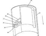
图4示出了根据本发明第二实施例的适于插进注射装置壳体内的螺纹内部部分10。螺纹11的主要部分为等螺距。但是,在螺纹12的下部内螺距急剧减少。这可见于轴边缘13的形式。由此当与螺纹11,12啮合的部分到达螺纹12的下部时,即,当其到达轴边缘13时,啮合部分可以突然地相对内部部分10沿轴向移动。这种突然移动,并且一点都不是当这个移动停止时随后的突然停止,可由用户感受到,如下文介绍的。而且,轴边缘13的位置朝向螺纹部分12的末端确保感觉到的突然移动指示设定剂量注射的末期。由此,非视觉(触觉)反馈信号作为在螺纹部分11,12的螺距变化结果而提供。Figure 4 shows a threaded
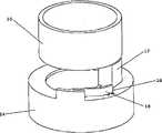
图5示出了适于围绕图4的螺纹内部部分10定位的外部部分14顶部视图。外部部分14设有两个突出部分15,每个突出部分适于与内部部分10的螺纹11,12啮合。FIG. 5 shows a top view of the
图6示出了沿图5中的线A-A的整个外部部分14的横截面。在剂量注射期间内部部分10和外部部分14以这样的方式相对初始地定位,即突出部分15与螺纹11的以下部分啮合,该部分的位置与螺纹12的下部相对。然后外部部分14被向内推,由此允许突出部分15沿螺纹11行进。由于螺纹11的原因内部部分10和外部部分14进行相对旋转运动。当突出部分15到达轴边缘13时,外部部分14的轴向速度将突然增加,如上所述,因为用户手工地按压外部部分14,这种突然移动,以及当外部部分14邻接存在于内螺纹部分10上(见图4)的停止部件16时发生的突然停止,将会被用户感觉到。由此提供了触觉反馈信号。而且,外部部分14突然地邻接停止部件16可产生声音,由此除了触觉信号外还提供声音反馈信号。FIG. 6 shows a cross-section of the entire
图7示出了根据本发明第三实施例的注射装置的部分。该图示出了内部部分10和外部部分14。内部部分10和外部部分14适于在注射期间彼此相对旋转。外部部分14设有楔构造17,内部部分10设有弹簧臂18。在注射过程中,除了相互旋转,内部部分10沿箭头指示的轴向移动。当弹簧臂18到达楔构造17时,弹簧臂18的突出部分19与楔构造17的上部20接合。这会导致弹簧臂18在与箭头指示的方向相反的方向被按下,由此使弹簧臂18拉紧。因此,拉紧是在注射期间产生的。突出部分19随后沿楔构造17的上部20移动直至其到达楔构造17的末端21。突出部分19然后‘越过边缘落下’到达图7所示的位置,由此释放弹簧臂18先前建立的拉紧。由于弹簧臂18移动空气和/或突出部分19撞击外部部分14的固定部分,这种拉紧的突然释放产生声音。由此产生声音反馈信号,并通过以适当方式放置楔构造17,反馈信号将向用户指示设定剂量已经注射了。Figure 7 shows part of an injection device according to a third embodiment of the invention. The figure shows the
当要设定新的剂量时,突出部分19将经楔构造17上的锥形部分22通过楔构造17。When a new dose is to be set, the protruding
图8示出了根据本发明第四实施例的注射装置的部分。第四实施例与图7所示的第三实施例非常相似。图8还示出了具有弹簧臂18的内部部分10和具有楔构造17的外部部分14,内部部分10和外部部分14适于在注射期间彼此相对旋转。弹簧臂设有突出部分19。在注射期间内部部分10相对外部部分14沿箭头指示的方向上移动。当弹簧臂到达楔构造17时,突出部分19可被抓持在轨道23内并沿这个轨道23移动。由于楔构造17的几何结构,这种移动会导致弹簧臂18在远离外部部分14的方向上被按压,由此在弹簧臂18内产生拉紧。因此,在注射期间产生了拉紧。当突出部分19到达楔构造17的末端21时,其将‘越过边缘落下’,由此释放先前在弹簧臂18内产生的拉紧。这会产生如上所述的声音反馈信号。Figure 8 shows part of an injection device according to a fourth embodiment of the invention. The fourth embodiment is very similar to the third embodiment shown in FIG. 7 . Figure 8 also shows an
当要设定新的剂量时,突出部分19将通过在轴向上沿楔构造17的末端21被抬升而通过楔构造17。When a new dose is to be set, the protruding
图9示出了根据本发明第五实施例的注射装置的部分。图9示出了具有弹簧臂18的内部部分10和具有楔构造17的外部部分14。在注射期间,内部部分10将在箭头指示的方向上相对外部部分14移动。但是,在这个实施例中内部部分10和外部部分14不相对彼此旋转。代替的是,注射装置包括旋转部分24,其在注射期间相对内部部分10和外部部分14旋转。当弹簧臂18到达楔构造17时,其在远离外部部分14和朝向旋转部分24的方向被推动。由此其被移进旋转部分24上的突出部分25的路径内。当突出部分25旋转至弹簧臂18的位置时,其因此再次将弹簧臂18推出其路径,由此在弹簧臂18内产生拉紧。当突出部分25已经通过弹簧臂18的位置时,弹簧臂18将再次释放从而移进突出部分25的路径内,由此释放了先前在弹簧臂18内产生的拉紧。由此由于弹簧臂18移动空气和/或弹簧臂18撞击旋转部分24的壁而产生声音反馈信号。Fig. 9 shows part of an injection device according to a fifth embodiment of the invention. FIG. 9 shows an
图10示出了根据本发明第六实施例的注射装置的部分。该图示出了具有弹簧臂18的内部部分10和具有楔构造17的外部部分14。内部部分10和外部部分14适于在注射期间相对彼此旋转。而且,在注射期间,内部部分10相对外部部分14在箭头指示的方向移动。当弹簧臂18到达楔构造17时,其将被多个楔中的一个抓持。由于楔构造17的几何结构和内部部分10的连续旋转和轴向运动(在箭头方向),弹簧臂18将在与箭头指示的方向相反的方向被按压,由此在弹簧臂18内产生拉紧。随后当弹簧臂18到达楔的末端21时,其将‘越过边缘落下’,由此释放先前产生的拉紧。这会产生如上所述的声音反馈信号。Fig. 10 shows part of an injection device according to a sixth embodiment of the invention. The figure shows an
图11示出了根据本发明第七实施例的注射装置的部分。该图示出了具有楔构造17的内部部分10和具有弹簧臂18和锁定机构(图11未示出)的外部部分14。内部部分10和外部部分14适于在设定剂量和注射期间相对彼此旋转。内部部分10典型地为刻度鼓或适于在设定剂量和注射期间随同刻度鼓旋转。这样,当设定了剂量时,内部部分10以这样的方式旋转,即楔构造17向外按压弹簧臂18并进入与锁定机构接合状态,由此在弹簧臂18内产生拉紧。这样,在这个实施例中,在剂量的设定过程中产生了拉紧。在剂量的其余设定期间和注射的主要部分期间,锁定机构将保持弹簧臂18处于拉紧位置。但是,当内部部分10回到初始位置时,楔构造17上的释放机构26释放锁定机构,由此释放先前在弹簧臂18内产生的拉紧。由此产生如上所述的声音信号,并因为当内部部分10回到初始位置时锁定机构被释放,这种声音信号指示设定剂量已经注射了。Fig. 11 shows part of an injection device according to a seventh embodiment of the invention. The figure shows an
图12示出了图11的注射装置的外部部分14。外部部分14具有处于锁定位置的锁定机构27,即其接合了弹簧臂18。这样,在图12中,弹簧臂18被拉紧。当内部部分(未示出)靠近外部部分14时,如上所述,释放机构(未示出)将向下推动锁定机构27,然后拉紧的弹簧臂18将恢复其松弛位置,即,其将朝向外部部分14的中心移动。由此在弹簧臂18内产生的拉紧被突然释放。FIG. 12 shows the
图13示出了注射装置1的部分,其包括位于注射装置1的近端的刻度鼓28和弹簧臂部件29。弹簧臂部件29设有弹簧臂18,该臂可沿近端方向偏转,即远离刻度鼓28的方向。FIG. 13 shows a part of the
在设定剂量的注射期间,刻度鼓28进行旋转运动和朝向弹簧臂部件29的轴向移动。这种运动最终使刻度鼓的上部30邻接弹簧臂18的突起31。由于刻度鼓28连续旋转和轴向移动,弹簧臂18沿近端方向偏转,由此在弹簧臂18内产生拉紧。During injection of a set dose, the
图13示出了刻度鼓29的上部30和弹簧臂18的突起31邻接并且已经在弹簧臂18内开始产生拉紧的情况。FIG. 13 shows the situation where the
图14示出了图13的注射装置。图14中,如上所述,已经在弹簧臂18内产生了拉紧。弹簧臂18的突起31位于非常靠近在刻度鼓28内形成的凹进部分32。这样,刻度鼓28的进一步旋转将使突起31‘越过边缘落下’并进入凹进部分32内。由此先前在弹簧臂18内产生的拉紧被释放,并且通过振动空气和/或由突起31撞击凹进部分32的下部边缘产生声音反馈信号。FIG. 14 shows the injection device of FIG. 13 . In Fig. 14 tension has been created in the
这种情况在图15中示意,示出了图13和14的注射装置处于上述的先前在弹簧臂18内产生的拉紧已经被释放的情况。This situation is schematically illustrated in Figure 15, showing the injection device of Figures 13 and 14 in a situation where the tension previously created in the
当要设定新的剂量时,反馈机构需要复位以便能够在后来的剂量已经被注射时提供声音反馈信号。这是通过在下一个剂量设定过程中引导弹簧臂18的凸起31经过位于刻度鼓28的上部30之后的路径或轨道(图13-15中未示出)实现的。当设定剂量足够大时,刻度鼓28和弹簧臂部件29会充分地间隔开以便允许突起31定位在刻度鼓28的上部30之上。由此复位了反馈机构,即弹簧臂18再次准备如上所述沿近端方向偏转。When a new dose is to be set, the feedback mechanism needs to be reset in order to be able to provide an audible feedback signal when a subsequent dose has been injected. This is achieved by guiding the
图13-15所示的注射装置尤其适于具有适合借助例如弹簧的机械偏压机构操作的剂量输送机构。The injection device shown in Figures 13-15 is particularly adapted to have a dose delivery mechanism adapted to be operated by means of a mechanical biasing mechanism, eg a spring.
前面已经示出了一些优选实施例,但是应当注意本发明不限于这些,而是可以以下述权利要求所限定的主题范围内其他的方式实现。Some preferred embodiments have been shown above, but it should be noted that the invention is not restricted to these but can be implemented in other ways within the scope of the subject-matter defined in the following claims.
Claims (12)
Applications Claiming Priority (3)
| Application Number | Priority Date | Filing Date | Title |
|---|---|---|---|
| EP05075187 | 2005-01-25 | ||
| EP05075187.4 | 2005-01-25 | ||
| PCT/EP2006/000486WO2006079481A1 (en) | 2005-01-25 | 2006-01-20 | An injection device with an end of dose feedback mechanism |
Publications (2)
| Publication Number | Publication Date |
|---|---|
| CN101107032A CN101107032A (en) | 2008-01-16 |
| CN101107032Btrue CN101107032B (en) | 2010-09-29 |
Family
ID=34938013
Family Applications (1)
| Application Number | Title | Priority Date | Filing Date |
|---|---|---|---|
| CN2006800030975AActiveCN101107032B (en) | 2005-01-25 | 2006-01-20 | Injection device with dose feedback mechanism tip |
Country Status (12)
| Country | Link |
|---|---|
| US (4) | US9457154B2 (en) |
| EP (1) | EP1877119B1 (en) |
| JP (2) | JP5340603B2 (en) |
| CN (1) | CN101107032B (en) |
| AU (1) | AU2006208606B2 (en) |
| BR (1) | BRPI0607012A2 (en) |
| CA (1) | CA2595323C (en) |
| DK (1) | DK1877119T3 (en) |
| ES (1) | ES2689536T3 (en) |
| PL (1) | PL1877119T3 (en) |
| RU (1) | RU2401134C2 (en) |
| WO (1) | WO2006079481A1 (en) |
Families Citing this family (115)
| Publication number | Priority date | Publication date | Assignee | Title |
|---|---|---|---|---|
| PL1877119T3 (en)* | 2005-01-25 | 2019-03-29 | Novo Nordisk A/S | An injection device with an end of dose feedback mechanism |
| WO2009086650A1 (en)* | 2008-01-11 | 2009-07-16 | Medmix Systems Ag | Dispensing appliance for a multiple cartridge |
| US8500682B2 (en) | 2008-09-18 | 2013-08-06 | Becton, Dickinson And Company | Medical injector with post-autoreconstitution dose setting and autoplunger drive |
| WO2010072229A1 (en)* | 2008-12-22 | 2010-07-01 | Tecpharma Licensing Ag | Dosing device for an injection device |
| EP2201972A1 (en)* | 2008-12-23 | 2010-06-30 | Sanofi-Aventis Deutschland GmbH | Fixed dose injection device with resettable drive mechanism |
| CA2753138C (en) | 2009-02-27 | 2017-11-14 | Lifescan, Inc. | Medical module for drug delivery pen |
| US9345840B2 (en) | 2009-06-01 | 2016-05-24 | Sanofi-Aventis Deutschland Gmbh | Drug delivery dose setting mechanism with variable maximum dose |
| US8974423B2 (en) | 2009-06-01 | 2015-03-10 | Sanofi-Aventis Deutschland Gmbh | Resettable drug delivery device |
| US8672896B2 (en) | 2009-06-01 | 2014-03-18 | Sanofi-Aventis Deutschland Gmbh | Inner housing for a drug delivery device |
| US9623187B2 (en) | 2009-06-01 | 2017-04-18 | Sanofi-Aventis Deutschland Gmbh | Resettable drug delivery device |
| US9457150B2 (en) | 2009-06-01 | 2016-10-04 | Sanofi-Aventis Deutschland Gmbh | Biasing mechanism for a drug delivery device |
| US8728043B2 (en) | 2009-06-01 | 2014-05-20 | Sanofi-Aventis Deutschland Gmbh | Drive mechanism for a drug delivery device |
| US8257319B2 (en) | 2009-06-01 | 2012-09-04 | Sanofi-Aventis Deutschland Gmbh | Drug delivery device inner housing having helical spline |
| US9199040B2 (en) | 2009-06-01 | 2015-12-01 | Sanofi-Aventis Deutschland Gmbh | Drug delivery device last dose lock-out mechanism |
| US9463283B2 (en) | 2009-06-01 | 2016-10-11 | Sanofi-Aventis Deutschland Gmbh | Dosing mechanism for a drug deliver device |
| US9108007B2 (en) | 2009-06-01 | 2015-08-18 | Sanofi-Aventis Deutschland Gmbh | Spindle and bearing combination and drug delivery device |
| US10034982B2 (en) | 2009-06-01 | 2018-07-31 | Sanofi-Aventis Deutschland Gmbh | Spindle for a drug delivery device |
| US8585656B2 (en) | 2009-06-01 | 2013-11-19 | Sanofi-Aventis Deutschland Gmbh | Dose setting mechanism for priming a drug delivery device |
| US9238106B2 (en) | 2009-06-01 | 2016-01-19 | Sanofi-Aventis Deutschland Gmbh | Dose setting mechanism for priming a drug delivery device |
| US9950116B2 (en) | 2009-06-01 | 2018-04-24 | Sanofi-Aventis Deutschland Gmbh | Dose setting mechanism for priming a drug delivery device |
| US9125994B2 (en) | 2009-06-01 | 2015-09-08 | Sanofi—Aventis Deutschland GmbH | Drug delivery device with dose dial sleeve rotational stop |
| US8672873B2 (en) | 2009-08-18 | 2014-03-18 | Cequr Sa | Medicine delivery device having detachable pressure sensing unit |
| US8547239B2 (en) | 2009-08-18 | 2013-10-01 | Cequr Sa | Methods for detecting failure states in a medicine delivery device |
| US8870831B2 (en)* | 2009-08-24 | 2014-10-28 | Shl Group Ab | Dose reset mechanism |
| JP5701889B2 (en) | 2009-10-08 | 2015-04-15 | エス・ホー・エル・グループ・アクチボラゲットShl Group Ab | Drug supply device |
| ES2749395T3 (en) | 2009-11-20 | 2020-03-20 | Becton Dickinson Co | Injection device without the need for a gear |
| ES2909887T3 (en)* | 2009-12-01 | 2022-05-10 | Becton Dickinson Co | Injection pen with automatic return and last dose control |
| US11957885B2 (en)* | 2010-02-09 | 2024-04-16 | Shl Medical Ag | Medicament delivery device |
| EP2583708B1 (en)* | 2010-03-31 | 2023-02-22 | SHL Medical AG | Medicament delivery device comprising feedback signalling means |
| RU2593984C1 (en)* | 2010-03-31 | 2016-08-10 | Схл Груп Аб | Drug administration device comprising signal feedback |
| EP2399635A1 (en) | 2010-06-28 | 2011-12-28 | Sanofi-Aventis Deutschland GmbH | Auto-injector |
| EP2407250A1 (en)* | 2010-07-16 | 2012-01-18 | 3M Innovative Properties Company | A device for dispensing a dental material |
| US8864721B2 (en) | 2010-09-24 | 2014-10-21 | Eli Lilly And Company | Gearing mechanism for a dose delivery device |
| EP2438940A1 (en)* | 2010-10-08 | 2012-04-11 | Sanofi-Aventis Deutschland GmbH | Auto injector with a torsion spring |
| BR112013009080A2 (en) | 2010-10-13 | 2016-07-19 | Sanofi Aventis Deutschland | Dosage mechanism and method of dose determination |
| US9211378B2 (en) | 2010-10-22 | 2015-12-15 | Cequr Sa | Methods and systems for dosing a medicament |
| EP2489387A1 (en) | 2011-02-18 | 2012-08-22 | Sanofi-Aventis Deutschland GmbH | Auto-injector |
| EP2489386A1 (en) | 2011-02-18 | 2012-08-22 | Sanofi-Aventis Deutschland GmbH | Auto-injector |
| EP2489380A1 (en)* | 2011-02-18 | 2012-08-22 | Sanofi-Aventis Deutschland GmbH | Injection device |
| EP2489388A1 (en) | 2011-02-18 | 2012-08-22 | Sanofi-Aventis Deutschland GmbH | Auto-injector |
| EP2489389A1 (en) | 2011-02-18 | 2012-08-22 | Sanofi-Aventis Deutschland GmbH | Detent mechanism |
| EP2489390A1 (en)* | 2011-02-18 | 2012-08-22 | Sanofi-Aventis Deutschland GmbH | Detent mechanism |
| EP2489381A1 (en) | 2011-02-18 | 2012-08-22 | Sanofi-Aventis Deutschland GmbH | Auto-injector |
| EP2489385A1 (en) | 2011-02-18 | 2012-08-22 | Sanofi-Aventis Deutschland GmbH | Auto-injector |
| EP2489382A1 (en) | 2011-02-18 | 2012-08-22 | Sanofi-Aventis Deutschland GmbH | Auto-injector |
| EP2489384A1 (en) | 2011-02-18 | 2012-08-22 | Sanofi-Aventis Deutschland GmbH | Auto-injector |
| GB2488578B (en)* | 2011-03-02 | 2017-05-24 | Owen Mumford Ltd | Injection device |
| EP3878495B1 (en) | 2011-03-16 | 2024-06-12 | Becton, Dickinson and Company | Multiple use disposable injection pen |
| US11577029B2 (en) | 2012-03-15 | 2023-02-14 | Becton, Dickinson And Company | Multiple use disposable injection pen |
| US12350474B2 (en) | 2011-03-16 | 2025-07-08 | Becton, Dickinson And Company | Multiple use disposable injection pen |
| US9452265B2 (en) | 2011-03-18 | 2016-09-27 | Becton, Dickinson And Company | End of injection indicator for injection pen |
| CN102205156B (en)* | 2011-05-23 | 2012-07-25 | 庄青山 | Dual-quantization injector special for insulin |
| EP2540330A1 (en)* | 2011-06-30 | 2013-01-02 | Sanofi-Aventis Deutschland GmbH | Needle assembly system |
| EP2583707A1 (en)* | 2011-10-21 | 2013-04-24 | Sanofi-Aventis Deutschland GmbH | Auto-injector |
| US9468722B2 (en) | 2011-11-25 | 2016-10-18 | Shl Group Ab | Medicament delivery device |
| RU2571332C1 (en)* | 2011-11-25 | 2015-12-20 | Схл Груп Аб | Medical delivery device |
| JP6336401B2 (en)* | 2012-02-21 | 2018-06-06 | ノボ・ノルデイスク・エー/エス | Dose end indicator |
| EP2644218B2 (en) | 2012-03-30 | 2022-11-02 | Tecpharma Licensing AG | Injection device with dose display and clockwork drive |
| EP2830685B1 (en) | 2012-03-30 | 2017-05-31 | Tecpharma Licensing AG | Injection device with a dose display element displaceable relative to a housing. |
| EP2644217A1 (en)* | 2012-03-30 | 2013-10-02 | TecPharma Licensing AG | Injection device with dose display and clockwork drive |
| EP2692377B1 (en) | 2012-08-01 | 2019-11-06 | TecPharma Licensing AG | Injection device with dose display element for signalling end of injection |
| EP2698179A1 (en) | 2012-08-14 | 2014-02-19 | Sanofi-Aventis Deutschland GmbH | Injection device |
| WO2014037946A1 (en)* | 2012-09-05 | 2014-03-13 | Elcam Medical Agricultural Cooperative Association Ltd. | Electronic auto-injection device |
| WO2014040929A1 (en) | 2012-09-11 | 2014-03-20 | Sanofi-Aventis Deutschland Gmbh | Drive mechanism for a drug delivery device and drug delivery device |
| DK2968783T3 (en)* | 2013-03-13 | 2021-07-12 | Sanofi Aventis Deutschland | MEDICINE DELIVERY DEVICE WITH A FEEDBACK FUNCTION |
| JP6480350B2 (en) | 2013-03-13 | 2019-03-06 | サノフィ−アベンティス・ドイチュラント・ゲゼルシャフト・ミット・ベシュレンクテル・ハフツング | Assembly of drug delivery device including feedback function |
| EP3590568A1 (en)* | 2013-03-22 | 2020-01-08 | TecPharma Licensing AG | Substance dispensing device with a signalling device |
| HK1214989A1 (en)* | 2013-04-10 | 2016-08-12 | Sanofi | Injection device |
| EP2983754B1 (en) | 2013-04-10 | 2021-01-20 | Sanofi | Drive mechanism of a drug delivery device |
| CN105102022B (en)* | 2013-04-10 | 2019-02-01 | 赛诺菲 | Driving mechanism for medicine delivery device |
| AR095808A1 (en)* | 2013-04-10 | 2015-11-11 | Sanofi Sa | INJECTION DEVICE |
| MX2015014293A (en)* | 2013-04-10 | 2015-12-08 | Sanofi Sa | Injection device. |
| US10478564B2 (en) | 2013-04-10 | 2019-11-19 | Sanofi | Injection device |
| DK2983739T3 (en) | 2013-04-10 | 2020-06-29 | Sanofi Sa | DRIVE MECHANISM FOR A PHARMACEUTICAL ADMINISTRATION DEVICE |
| US10420897B2 (en) | 2013-05-07 | 2019-09-24 | Sanofi-Aventis Deutschland Gmbh | Supplemental device for attachment to an injection device |
| RU2669469C2 (en) | 2013-05-16 | 2018-10-11 | Санофи-Авентис Дойчланд Гмбх | Mechanism for drug delivery device |
| US10137251B2 (en)* | 2013-05-27 | 2018-11-27 | Sanofi-Aventis Deutschland Gmbh | Assembly for a drug delivery device and drug delivery device |
| JP6456928B2 (en)* | 2013-06-04 | 2019-01-23 | ノボ・ノルデイスク・エー/エス | Torsion spring type injection device having administration end mechanism |
| JP6480924B2 (en) | 2013-07-17 | 2019-03-13 | サノフイSanofi | Drug delivery device |
| CN105377331A (en) | 2013-07-17 | 2016-03-02 | 赛诺菲 | Drive mechanism |
| RU2535601C1 (en)* | 2013-07-22 | 2014-12-20 | ООО "Уральский центр биофармацевтических технологий" | Syringe handle device |
| BR122021026856B1 (en) | 2013-08-02 | 2023-02-14 | Becton, Dickinson And Company | INJECTION PEN |
| WO2015032783A1 (en)* | 2013-09-03 | 2015-03-12 | Sanofi | Drive mechanism and injection device herewith |
| US9962494B2 (en)* | 2013-11-22 | 2018-05-08 | Sanofi-Aventis Deutschland Gmbh | Drug delivery device with end of dose feedback |
| EA201692218A1 (en)* | 2014-06-06 | 2017-05-31 | Эли Лилли Энд Компани | TURNING MECHANISM TO GIVE A RESPONSE SIGNAL ON THE END OF DOSE |
| TW201603852A (en) | 2014-07-01 | 2016-02-01 | 賽諾菲公司 | Spring arrangement and drug delivery device herewith |
| EP3164177B1 (en)* | 2014-07-01 | 2019-08-21 | Sanofi | Drug delivery device |
| TW201603848A (en) | 2014-07-01 | 2016-02-01 | 賽諾菲公司 | Drug delivery device |
| TW201603849A (en)* | 2014-07-01 | 2016-02-01 | 賽諾菲公司 | Clicker arrangement and drug delivery herewith |
| TW201603851A (en) | 2014-07-01 | 2016-02-01 | 賽諾菲公司 | Drug delivery device |
| HK1244736A1 (en) | 2014-12-08 | 2018-08-17 | Sanofi | Clicker arrangement and drug delivery device herewith |
| CA3009221A1 (en) | 2014-12-23 | 2016-06-30 | Automed Pty Ltd | Delivery apparatus, system and associated methods |
| CA2969349A1 (en) | 2015-01-16 | 2016-07-21 | Eli Lilly And Company | Injection device with end of dose mechanism |
| TW201707737A (en) | 2015-06-03 | 2017-03-01 | 賽諾菲阿凡提斯德意志有限公司 | Drug delivery device (1) |
| TW201711713A (en) | 2015-06-03 | 2017-04-01 | 賽諾菲阿凡提斯德意志有限公司 | Drug delivery device |
| TW201709940A (en) | 2015-06-03 | 2017-03-16 | 賽諾菲阿凡提斯德意志有限公司 | Sound indicator (1) |
| TW201709941A (en) | 2015-06-03 | 2017-03-16 | 賽諾菲阿凡提斯德意志有限公司 | Sound indicator (2) |
| TW201700118A (en) | 2015-06-03 | 2017-01-01 | 賽諾菲阿凡提斯德意志有限公司 | Drug delivery device (3) |
| TW201707744A (en)* | 2015-06-03 | 2017-03-01 | 賽諾菲阿凡提斯德意志有限公司 | Drug delivery device (2) |
| EP3187213A1 (en) | 2015-12-29 | 2017-07-05 | Galderma S.A. | Syringe with click mechanism |
| EP3187217A1 (en) | 2015-12-29 | 2017-07-05 | Galderma S.A. | Syringe with click mechanism |
| CN106693119A (en)* | 2016-12-24 | 2017-05-24 | 北京糖护科技有限公司 | Device for automatically recording insulin injection dosage by sound control |
| CN106527293A (en)* | 2016-12-24 | 2017-03-22 | 北京糖护科技有限公司 | Circuit for automatically identifying and analyzing insulin pen injection sound |
| CN106730171A (en)* | 2016-12-24 | 2017-05-31 | 北京糖护科技有限公司 | A kind of acoustic control records the device and its circuit of insulin dosage automatically |
| US11517680B2 (en) | 2017-03-14 | 2022-12-06 | Sanofi | Injection device with an acoustic feedback arrangement |
| US11400232B2 (en) | 2017-11-03 | 2022-08-02 | Sanofi | Drug delivery device |
| US11654246B2 (en) | 2017-11-03 | 2023-05-23 | Sanofi | Drug delivery device |
| RU2680934C1 (en)* | 2017-12-04 | 2019-02-28 | Общество с ограниченной ответственностью "АйВиФарма" | Pen-type injector for the administration of a solution of a recombinant human follicle-stimulating hormone |
| CN110958901A (en)* | 2018-03-05 | 2020-04-03 | 波利医疗有限公司 | Intravenous catheter assembly |
| CN108535397B (en)* | 2018-04-12 | 2020-05-19 | 福建拓普检测技术有限公司 | Method for detecting n-hexane concentration in workplace |
| EP4037734A1 (en) | 2019-09-30 | 2022-08-10 | Amgen Inc. | Drug delivery device |
| CN110916852B (en)* | 2019-12-12 | 2025-05-02 | 上海纽脉医疗科技股份有限公司 | An outer tube moving mechanism and a valve delivery device |
| US11957542B2 (en) | 2020-04-30 | 2024-04-16 | Automed Patent Holdco, Llc | Sensing complete injection for animal injection device |
| US20240277936A1 (en)* | 2021-09-28 | 2024-08-22 | Shl Medical Ag | Feedback mechanism for a medicament delivery device |
| IL312672A (en) | 2021-11-10 | 2024-07-01 | I2O Therapeutics Inc | Ionic liquid compositions |
Citations (3)
| Publication number | Priority date | Publication date | Assignee | Title |
|---|---|---|---|---|
| US4592745A (en)* | 1984-02-29 | 1986-06-03 | Novo Industri A/S | Dispenser |
| CN1089510A (en)* | 1992-10-20 | 1994-07-20 | 伊莱利利公司 | dose indicator tip |
| EP0688571A1 (en)* | 1994-06-22 | 1995-12-27 | Becton, Dickinson and Company | Quick connect medication delivery pen |
Family Cites Families (18)
| Publication number | Priority date | Publication date | Assignee | Title |
|---|---|---|---|---|
| US688571A (en)* | 1901-03-18 | 1901-12-10 | James Airey | Packing for pistons. |
| IE52621B1 (en)* | 1981-02-12 | 1988-01-06 | Turner Robert Charles | Dose metering plunger devices for use with syringes |
| DE3638984C3 (en)* | 1986-11-14 | 1993-11-18 | Haselmeier Wilhelm Fa | Injection device |
| US5957889A (en) | 1993-09-27 | 1999-09-28 | Novo Nordisk A/S | Displacement system for controlled infusion of a liquid |
| US5582598A (en)* | 1994-09-19 | 1996-12-10 | Becton Dickinson And Company | Medication delivery pen with variable increment dose scale |
| JP3568959B2 (en) | 1995-03-07 | 2004-09-22 | イーライ・リリー・アンド・カンパニー | Reusable dosing device |
| US5501670A (en)* | 1995-03-31 | 1996-03-26 | Sak; Robert F. | Syringe system providing retraction of needle cannula into disposable cartridge |
| EP0959922B1 (en) | 1996-02-23 | 2003-05-21 | Novo Nordisk A/S | Syringe with electronic representation of parameters |
| DE69740097D1 (en) | 1996-03-12 | 2011-02-17 | Novo Nordisk As | Injection device with electronic display of the selected dose |
| US6796970B1 (en) | 1997-06-17 | 2004-09-28 | Novo Nordisk A/S | Dose setting device |
| CZ297361B6 (en) | 1998-01-30 | 2006-11-15 | Novo Nordisk A/S | Injection syringe |
| DE19819409A1 (en)* | 1998-04-30 | 1999-11-11 | Schering Ag | Injection device |
| DE19900792C1 (en) | 1999-01-12 | 2000-06-15 | Disetronic Licensing Ag | Injection unit forming part of e.g. pen-type self-injection syringe has continuous dosing stop in spiral form with constant pitch ensuring close fine control and accuracy in use |
| DE29912965U1 (en)* | 1999-07-24 | 1999-09-16 | Hoelzle Dieter Tech Projekte | Injection device |
| US6663602B2 (en) | 2000-06-16 | 2003-12-16 | Novo Nordisk A/S | Injection device |
| ES2365807T3 (en)* | 2001-05-16 | 2011-10-11 | ELI LILLY & COMPANY | MEDICATION INJECTOR DEVICE WITH MOTOR ASSEMBLY THAT FACILITATES REARME. |
| WO2004007002A1 (en) | 2002-07-10 | 2004-01-22 | Novo Nordisk A/S | An injection device |
| PL1877119T3 (en)* | 2005-01-25 | 2019-03-29 | Novo Nordisk A/S | An injection device with an end of dose feedback mechanism |
- 2006
- 2006-01-20PLPL06706325Tpatent/PL1877119T3/enunknown
- 2006-01-20CACA2595323Apatent/CA2595323C/ennot_activeExpired - Fee Related
- 2006-01-20WOPCT/EP2006/000486patent/WO2006079481A1/enactiveApplication Filing
- 2006-01-20EPEP06706325.5Apatent/EP1877119B1/enactiveActive
- 2006-01-20DKDK06706325.5Tpatent/DK1877119T3/enactive
- 2006-01-20USUS11/813,389patent/US9457154B2/enactiveActive
- 2006-01-20JPJP2007552556Apatent/JP5340603B2/enactiveActive
- 2006-01-20AUAU2006208606Apatent/AU2006208606B2/enactiveActive
- 2006-01-20CNCN2006800030975Apatent/CN101107032B/enactiveActive
- 2006-01-20BRBRPI0607012-4Apatent/BRPI0607012A2/ennot_activeApplication Discontinuation
- 2006-01-20RURU2007126416/14Apatent/RU2401134C2/enactive
- 2006-01-20ESES06706325.5Tpatent/ES2689536T3/enactiveActive
- 2013
- 2013-04-17JPJP2013086638Apatent/JP5568157B2/enactiveActive
- 2016
- 2016-08-19USUS15/241,566patent/US9861757B2/enactiveActive
- 2017
- 2017-11-17USUS15/815,976patent/US10357616B2/enactiveActive
- 2019
- 2019-06-06USUS16/433,082patent/US20190282762A1/ennot_activeAbandoned
Patent Citations (3)
| Publication number | Priority date | Publication date | Assignee | Title |
|---|---|---|---|---|
| US4592745A (en)* | 1984-02-29 | 1986-06-03 | Novo Industri A/S | Dispenser |
| CN1089510A (en)* | 1992-10-20 | 1994-07-20 | 伊莱利利公司 | dose indicator tip |
| EP0688571A1 (en)* | 1994-06-22 | 1995-12-27 | Becton, Dickinson and Company | Quick connect medication delivery pen |
Also Published As
| Publication number | Publication date |
|---|---|
| CN101107032A (en) | 2008-01-16 |
| US9861757B2 (en) | 2018-01-09 |
| ES2689536T3 (en) | 2018-11-14 |
| RU2401134C2 (en) | 2010-10-10 |
| CA2595323A1 (en) | 2006-08-03 |
| JP2013154219A (en) | 2013-08-15 |
| BRPI0607012A2 (en) | 2009-12-01 |
| RU2007126416A (en) | 2009-03-10 |
| US20180071459A1 (en) | 2018-03-15 |
| AU2006208606B2 (en) | 2011-10-06 |
| JP2008528144A (en) | 2008-07-31 |
| US20190282762A1 (en) | 2019-09-19 |
| EP1877119A1 (en) | 2008-01-16 |
| DK1877119T3 (en) | 2018-10-15 |
| JP5568157B2 (en) | 2014-08-06 |
| US9457154B2 (en) | 2016-10-04 |
| PL1877119T3 (en) | 2019-03-29 |
| US20160354548A1 (en) | 2016-12-08 |
| US20090012479A1 (en) | 2009-01-08 |
| US10357616B2 (en) | 2019-07-23 |
| JP5340603B2 (en) | 2013-11-13 |
| WO2006079481A1 (en) | 2006-08-03 |
| CA2595323C (en) | 2014-01-28 |
| EP1877119B1 (en) | 2018-09-05 |
| AU2006208606A1 (en) | 2006-08-03 |
Similar Documents
| Publication | Publication Date | Title |
|---|---|---|
| CN101107032B (en) | Injection device with dose feedback mechanism tip | |
| RU2754301C2 (en) | Data collection device attached to injection device | |
| CN101903059B (en) | Injection devices for the delivery of fixed-dose liquid medications | |
| JP5635187B2 (en) | Drug delivery device | |
| EP1855743B2 (en) | Dose setting mechanism for an injection device capable of presetting a maximum dose | |
| JP5178202B2 (en) | Injection device | |
| JP5451641B2 (en) | Injection device with mode defining element | |
| TWI569839B (en) | Medicament delivery device | |
| WO2018206494A1 (en) | Piston rod brake mechanism | |
| US20240100261A1 (en) | Medicament delivery device | |
| TW201201765A (en) | Medicament delivery device | |
| US20230191037A1 (en) | Drug delivery device with click sound during delivery | |
| CN110913929B (en) | Injection device with plunger means and converging ramp | |
| CN119280570A (en) | Injection pen and sound-generating device thereof |
Legal Events
| Date | Code | Title | Description |
|---|---|---|---|
| C06 | Publication | ||
| PB01 | Publication | ||
| C10 | Entry into substantive examination | ||
| SE01 | Entry into force of request for substantive examination | ||
| C14 | Grant of patent or utility model | ||
| GR01 | Patent grant |