CN101105921A - Information processing device and control method - Google Patents
Information processing device and control methodDownload PDFInfo
- Publication number
- CN101105921A CN101105921ACN200710129027.0ACN200710129027ACN101105921ACN 101105921 ACN101105921 ACN 101105921ACN 200710129027 ACN200710129027 ACN 200710129027ACN 101105921 ACN101105921 ACN 101105921A
- Authority
- CN
- China
- Prior art keywords
- brightness
- data
- pixel
- white pixel
- setting
- Prior art date
- Legal status (The legal status is an assumption and is not a legal conclusion. Google has not performed a legal analysis and makes no representation as to the accuracy of the status listed.)
- Granted
Links
Images


Classifications
- G—PHYSICS
- G09—EDUCATION; CRYPTOGRAPHY; DISPLAY; ADVERTISING; SEALS
- G09G—ARRANGEMENTS OR CIRCUITS FOR CONTROL OF INDICATING DEVICES USING STATIC MEANS TO PRESENT VARIABLE INFORMATION
- G09G3/00—Control arrangements or circuits, of interest only in connection with visual indicators other than cathode-ray tubes
- G09G3/20—Control arrangements or circuits, of interest only in connection with visual indicators other than cathode-ray tubes for presentation of an assembly of a number of characters, e.g. a page, by composing the assembly by combination of individual elements arranged in a matrix no fixed position being assigned to or needed to be assigned to the individual characters or partial characters
- G09G3/34—Control arrangements or circuits, of interest only in connection with visual indicators other than cathode-ray tubes for presentation of an assembly of a number of characters, e.g. a page, by composing the assembly by combination of individual elements arranged in a matrix no fixed position being assigned to or needed to be assigned to the individual characters or partial characters by control of light from an independent source
- G09G3/3406—Control of illumination source
- G—PHYSICS
- G09—EDUCATION; CRYPTOGRAPHY; DISPLAY; ADVERTISING; SEALS
- G09G—ARRANGEMENTS OR CIRCUITS FOR CONTROL OF INDICATING DEVICES USING STATIC MEANS TO PRESENT VARIABLE INFORMATION
- G09G2300/00—Aspects of the constitution of display devices
- G09G2300/04—Structural and physical details of display devices
- G09G2300/0439—Pixel structures
- G09G2300/0456—Pixel structures with a reflective area and a transmissive area combined in one pixel, such as in transflectance pixels
- G—PHYSICS
- G09—EDUCATION; CRYPTOGRAPHY; DISPLAY; ADVERTISING; SEALS
- G09G—ARRANGEMENTS OR CIRCUITS FOR CONTROL OF INDICATING DEVICES USING STATIC MEANS TO PRESENT VARIABLE INFORMATION
- G09G2320/00—Control of display operating conditions
- G09G2320/06—Adjustment of display parameters
- G09G2320/0626—Adjustment of display parameters for control of overall brightness
- G09G2320/0633—Adjustment of display parameters for control of overall brightness by amplitude modulation of the brightness of the illumination source
- G—PHYSICS
- G09—EDUCATION; CRYPTOGRAPHY; DISPLAY; ADVERTISING; SEALS
- G09G—ARRANGEMENTS OR CIRCUITS FOR CONTROL OF INDICATING DEVICES USING STATIC MEANS TO PRESENT VARIABLE INFORMATION
- G09G2330/00—Aspects of power supply; Aspects of display protection and defect management
- G09G2330/02—Details of power systems and of start or stop of display operation
- G09G2330/021—Power management, e.g. power saving
- G—PHYSICS
- G09—EDUCATION; CRYPTOGRAPHY; DISPLAY; ADVERTISING; SEALS
- G09G—ARRANGEMENTS OR CIRCUITS FOR CONTROL OF INDICATING DEVICES USING STATIC MEANS TO PRESENT VARIABLE INFORMATION
- G09G3/00—Control arrangements or circuits, of interest only in connection with visual indicators other than cathode-ray tubes
- G09G3/20—Control arrangements or circuits, of interest only in connection with visual indicators other than cathode-ray tubes for presentation of an assembly of a number of characters, e.g. a page, by composing the assembly by combination of individual elements arranged in a matrix no fixed position being assigned to or needed to be assigned to the individual characters or partial characters
- G09G3/34—Control arrangements or circuits, of interest only in connection with visual indicators other than cathode-ray tubes for presentation of an assembly of a number of characters, e.g. a page, by composing the assembly by combination of individual elements arranged in a matrix no fixed position being assigned to or needed to be assigned to the individual characters or partial characters by control of light from an independent source
- G09G3/36—Control arrangements or circuits, of interest only in connection with visual indicators other than cathode-ray tubes for presentation of an assembly of a number of characters, e.g. a page, by composing the assembly by combination of individual elements arranged in a matrix no fixed position being assigned to or needed to be assigned to the individual characters or partial characters by control of light from an independent source using liquid crystals
- G09G3/3607—Control arrangements or circuits, of interest only in connection with visual indicators other than cathode-ray tubes for presentation of an assembly of a number of characters, e.g. a page, by composing the assembly by combination of individual elements arranged in a matrix no fixed position being assigned to or needed to be assigned to the individual characters or partial characters by control of light from an independent source using liquid crystals for displaying colours or for displaying grey scales with a specific pixel layout, e.g. using sub-pixels
Landscapes
- Engineering & Computer Science (AREA)
- Physics & Mathematics (AREA)
- Computer Hardware Design (AREA)
- General Physics & Mathematics (AREA)
- Theoretical Computer Science (AREA)
- Control Of Indicators Other Than Cathode Ray Tubes (AREA)
- Liquid Crystal Display Device Control (AREA)
- Liquid Crystal (AREA)
Abstract
Description
Translated fromChinese技术领域technical field
本发明的一个实施例涉及一种具有RGBW型式LCD和照明单元的显示屏,具有该显示屏的信息处理装置,以及控制方法。One embodiment of the present invention relates to a display screen having an RGBW type LCD and a lighting unit, an information processing device having the display screen, and a control method.
背景技术Background technique
LCD(液晶显示器)广泛用作笔记本个人计算机和汽车导航系统的显示装置。LCDs (Liquid Crystal Displays) are widely used as display devices for notebook personal computers and car navigation systems.
目前建议使用RGBW型式的LCD以提高亮度。It is currently recommended to use an RGBW type LCD to increase brightness.
2006-3475号日本专利公开公报披露一种由输入装置(输入按键)来控制W像素的使用率(亮度)从而使显示器省电的有机场致发光装置。至于RGBW型式的LCD,W像素的亮度可以通过与2006-3475号日本专利公开公报所说明的情形类似的输入装置来改变。Japanese Patent Laid-Open Publication No. 2006-3475 discloses an organic electroluminescence device in which the utilization rate (brightness) of W pixels is controlled by an input device (input key) so as to save power for the display. As for the RGBW type LCD, the brightness of the W pixel can be changed by an input device similar to that described in Japanese Patent Laid-Open Publication No. 2006-3475.
液晶本身不发光,LCD与诸如背光的照明相结合,以便用户可看到图像。背光所消耗的电量大于LCD。因此,对于笔记本个人计算机,笔记本个人计算机由电池供电时背光的亮度自动降低来延长驱动时间。背光的亮度降低时存在可视性降低这种情况。Liquid crystals do not emit light by themselves, and LCDs are combined with lighting such as backlights so that users can see images. Backlights consume more power than LCDs. Therefore, for a notebook personal computer, the brightness of the backlight of the notebook personal computer is automatically lowered to prolong the driving time when the notebook computer is powered by a battery. When the brightness of the backlight is lowered, visibility may be lowered.
发明内容Contents of the invention
本发明的目的在于提供一种可以在照明亮度降低时抑制可视性降低的信息处理装置以及控制方法。An object of the present invention is to provide an information processing device and a control method capable of suppressing a decrease in visibility when illumination brightness decreases.
根据本发明的一个方面,提供了一种信息处理装置,其包括:其中包括显示屏、用于驱动白色像素的驱动电路、照明单元、以及对该照明单元提供升高的驱动电源的逆变器的显示单元;对逆变器提供与第二控制信号相对应的驱动电源的电源;从包括包含白色像素亮度设置和照明单元亮度设置的多个设置数据项的设置表中选择一个设置数据项的选择单元;对驱动电路提供与所选定的项中所包含的白色像素的亮度相对应的第一控制信号的第一控制信号输出单元;以及对电源提供与所选定的项中所包含的照明单元的亮度相对应的第二控制信号的第二控制信号输出单元。According to one aspect of the present invention, there is provided an information processing device, which includes: including a display screen, a driving circuit for driving white pixels, a lighting unit, and an inverter for supplying a boosted driving power to the lighting unit The display unit of the display unit; the inverter is provided with the power supply corresponding to the second control signal driving power; from the setting table including a plurality of setting data items including white pixel brightness setting and lighting unit brightness setting, selecting a setting data item A selection unit; a first control signal output unit that provides a first control signal corresponding to the brightness of a white pixel included in the selected item to the driving circuit; The brightness of the lighting unit corresponds to the second control signal output unit of the second control signal.
即便是照明亮度降低,也可抑制可视性降低。Even if the illumination brightness is lowered, the decrease in visibility can be suppressed.
附图说明Description of drawings
图1是示出本发明第一实施例作为信息处理装置的个人计算机其中一例示意性配置的示范性立体图;1 is an exemplary perspective view showing one example of a schematic configuration of a personal computer as an information processing apparatus according to a first embodiment of the present invention;
图2是示出第一实施例的个人计算机其中一例电路配置的示范性框图;2 is an exemplary block diagram showing one example of the circuit configuration of the personal computer of the first embodiment;
图3是示出实用程序在LCD上显示的在同步模式和异步模式之间切换的窗口的示意图;FIG. 3 is a schematic diagram showing a window switched between a synchronous mode and an asynchronous mode displayed on an LCD by a utility;
图4是示出在透射型LCD情况下,同步数据表中内容的示意图;Fig. 4 is a schematic diagram showing the content in the synchronous data table in the case of a transmissive LCD;
图5是示出在半透明型LCD情况下,同步数据表中内容的示意图;Fig. 5 is a schematic diagram showing the content in the synchronous data table in the case of a translucent LCD;
图6是示出在反射型LCD情况下,同步数据表中内容的示意图;Fig. 6 is a schematic diagram showing the content in the synchronous data table in the case of reflective LCD;
图7是示出在透射型LCD情况下,用于设置白色像素和背光亮度的处理步骤的示范性流程图;FIG. 7 is an exemplary flowchart showing the processing steps for setting white pixels and backlight brightness in the case of a transmissive LCD;
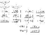
图8是示出在半透明型和反射型LCD情况下,用于设置白色像素和背光亮度的处理步骤的流程图。Fig. 8 is a flowchart showing the processing steps for setting white pixels and backlight brightness in the case of translucent and reflective LCDs.
具体实施方式Detailed ways
下面参照附图说明本发明种种实施例。Various embodiments of the present invention will be described below with reference to the accompanying drawings.
现参照附图说明本发明其中一实施例。One embodiment of the present invention will now be described with reference to the accompanying drawings.
图1是示出本发明第一实施例作为信息处理装置的个人计算机其中一例示意性配置的示范性立体图。1 is an exemplary perspective view showing one example of a schematic configuration of a personal computer as an information processing apparatus according to a first embodiment of the present invention.
个人计算机10由计算机主体12和显示单元14组成。显示单元14其中结合的显示屏16具有LCD(液晶显示器)。The
作为显示用单元的显示单元14与计算机主体12后侧边缘部所设置的铰链(支持部)18附接,从而可以在覆盖计算机主体12上表面用的打开位置和使计算机主体12上表面外露用的关闭位置之间以可转动方式改变。The
计算机主体12具有呈浅薄盒形的壳体。有键盘20设置于该壳体上表面的中央部。手掌支撑部形成于计算机主体12的壳体部其上表面的前侧。手掌支撑部的大体中央部位设置有触摸片22、滚屏按钮24、以及触摸片控制按钮26。计算机主体12壳体部的上表面的后侧配置有用于打开和关闭计算机主体12电源的电源按钮28。The computer
接下来参照图2说明本计算机的一例系统配置。Next, an example of the system configuration of this computer will be described with reference to FIG. 2 .
如图2所示,本计算机其中包括CPU 102、北桥104、主存储器114、图形控制器108、南桥106、BIOS-ROM 120、硬盘驱动器(HDD)126、嵌入式控制器/键盘控制器IC(EC/KBC)130、电源125等。As shown in Figure 2, the computer includes
显示单元14具有包含LCD 161的显示屏、RGB驱动电路(RGB驱动器)162、W驱动电路(W驱动器)163、背光164、第一连接器C1和第二连接器C2、以及逆变器15。The
LCD 161的滤色器是具有红、绿、蓝、和白滤色波段的RGBW型式(例如清楚和无色)的滤色器。背光164是用于从透射型(或半透明型)LCD 161的背面对该LCD 161进行照明的照明单元。当LCD 161是反射型时,前侧光用作从LCD 161的前侧对LCD 161进行照明的照明单元。逆变器15对电源125提供的驱动电源进行升压,并且将升压后的电源提供给背光164。The color filters of the
CPU 102是用于控制本计算机运作而设置的处理器。CPU 102执行包括从硬盘驱动器(HDD)126加载到主存储器114中的包括操作系统(OS)151和实用程序152在内的各种应用程序。此外,在启动时将同步数据表153加载到主存储器114中。The
此外,CPU 102将BIOS-ROM 120中所存储的系统BIOS(基本输入输出系统)加载到主存储器114中,然后执行系统BIOS。该系统BIOS是用于控制硬件的程序。Furthermore, the
北桥104是用于连接CPU 102的局部总线和南桥106的桥接装置。北桥104其中结合有用于对主存储器114进行存取控制的存储控制器。另外,南桥104具有通过AGP(图形加速端口)总线等与图形控制器108进行通信的功能。The
图形控制器108是用于控制用作本计算机显示器的LCD 161的红色像素、绿色像素和蓝色像素的显示控制器。图形控制器108具有视频存储器(VRAM)。图形控制器108根据OS和应用程序在视频存储器中提供的显示数据产生形成LCD 161上所显示的显示图像的视频信号。作为由图形控制器108所产生的控制信号的视频信号输出给信号线L1。信号线L1与显示屏16中设置的第一连接器C1相连接。显示屏16中设置的RGB驱动电路162基于第一连接器C1所提供的视频信号来驱动LCD 161的红、绿和蓝色像素。The
嵌入式控制器/键盘控制器IC 130对触控盘22、滚屏按钮24和触控盘控制按钮26进行控制,并且还起到控制LCD 161的背光和白色像素亮度的控制器这种作用。嵌入式控制器/键盘控制器IC 130是一不论计算机10的系统状态如何均监视和控制各种设备(外围设备、传感器、电源电路等)的单芯片微型计算机。Embedded controller/keyboard controller IC 130
此外,EC/KBC 130具有白色像素亮度寄存器(W像素亮度寄存器)131、背光亮度寄存器(BL亮度寄存器)132、W像素PWM电路133、以及BL_PWM电路134。白色像素亮度寄存器131所存储的数据用于指定LCD 161白色像素的亮度。背光亮度寄存器132所存储的数据用于指定背光171的亮度。In addition, the EC/
W像素PWM电路133基于白色像素亮度寄存器131中存储的数据产生作为控制信号的PWM信号。由W像素PWM电路133产生的作为控制信号的PWM信号输出给信号线L2。信号线L2与显示屏16中设置的第二连接器C2相连接。显示屏中设置的W驱动电路163基于第二连接器C2提供的视频信号驱动LCD 161的白色像素。The W
BL_PWM电路134基于背光亮度寄存器132中存储的数据产生作为控制信号的PWM信号。电源125对逆变器15提供电压值基于PWM信号的驱动电源。将逆变器15升压后的电源提供给背光164,由此背光164进行照明。The
当通过AC(交流)适配器125B由外部电源提供电源125时,电源125通过使用AC适配器125B所提供的外部电源产生要提供给本计算机10的各个组成部分的系统电源。此外,当并非通过AC适配器125B由外部电源提供电源125时,则使用电池125A产生要提供给本计算机10的各个组成部分(计算机主体12和显示单元(显示用单元)14)的系统电源。下面计算机主体12和显示单元14的驱动电源是电池125A的情况,均称为电池驱动。When the
电源125具有在系统电源的产生位置发生变化时针对EC/KBC 130进行中断以报告系统电源的产生位置。EC/KBC 130将系统电源的产生位置报告给系统BIOS。系统BIOS根据系统电源的产生位置使得主存储器114上的BATT(电池)驱动标志154为允许(电池驱动)或禁止(外部电源驱动)。The
接下来说明对白色像素的控制。Next, the control of white pixels will be described.
由EC/KBC 130执行对白色像素的控制。对白色像素的控制具有对白色像素的控制和对背光亮度的控制自动进行的同步模式,和对背光亮度的控制和对白色像素的控制可以由用户独立设置的异步模式。Control of white pixels is performed by EC/
同步模式和异步模式之间的切换由实用程序152进行。图3示出实用程序152在LCD161上显示的在同步模式和异步模式两者间切换的窗口。Switching between synchronous and asynchronous modes is performed by
如图3所示,窗口170中有用于选择同步模式的单选框171和用于选择异步模式的单选框172。单选框171和172不能复选。在单选框171和单选框172其中已经有一个被选中的情况下又选中单选框171和单选框172其中另一个时,将单选框171和单选框172中先前选中的一个勾选标志自动变为未被勾选的标志。选择的是同步模式还是异步模式的设置存储于充当存储装置的CMOS RAM 140的同步/异步设置141中。As shown in FIG. 3 , there is a
在同步模式下,白色像素和背光的亮度根据加载到例如EC/KBC的主存储器114中的同步数据表153中的设置数据进行控制。图4、图5和图6示出该同步数据表153中一例内容。图4是LCD 161为透射型的情况下同步数据表153的内容。图5是LCD 161为半透明型的情况下同步数据表153的内容。图6是LCD 161为反射型的情况下同步数据表153的内容。In synchronous mode, the brightness of the white pixels and the backlight are controlled according to the setting data in the synchronous data table 153 loaded into the
图4、图5和图6中,在AC适配器125B供电的情况下,高功率属于系统由AC电源驱动的情形。此外,普通模式和长寿命模式属于系统由电池125A驱动的情形。通过将图3所示的窗口170中的复选框173置为有效,选择长寿命模式。通过将复选框173置为无效来选择普通模式。是长寿命模式还是普通模式的选择记录于同步/异步设置141中。In Fig. 4, Fig. 5 and Fig. 6, in the case of
选择了异步模式时,可以操作用于设置白色像素亮度的滑动条174和用于设置背光亮度的滑动条175。白色像素的亮度可按4个等级设置。背光的亮度可按256个等级设置。用户设置的白色像素和背光的亮度值记录于同步/异步设置141中。When the asynchronous mode is selected, the
接下来将用于设置背光和白色像素亮度的处理步骤说明如下。同步模式控制两个状态,即光从背光通过白色像素的导通状态和没有光从背光通过白色像素的截止状态。此外,背光控制4种状态,即高亮度、中亮度、低亮度、和截止状态。对于对白色像素和背光的控制来说,可以增加若干个步骤来进行该控制。Next, the processing steps for setting the brightness of the backlight and white pixels are described below. Synchronous mode controls two states, the on state where light passes from the backlight to the white pixels and the off state where no light passes from the backlight to the white pixels. In addition, the backlight controls 4 states, namely high brightness, middle brightness, low brightness, and off state. For the control of white pixels and backlight, several steps can be added to perform this control.
-透射型LCD-Transmissive LCD
首先,说明LCD 161属于透射型的情形。启动时或者切换模式时,实用程序152参照同步/异步设置141来判断是否选择同步模式(步骤S11)。当判断选择了同步模式(步骤S11中为是的情形)时,实用程序152便判断系统电流源是否为电池125A(步骤S12)。First, the case where the
判断供电电源并非电池125A(步骤S12中为否的情形)时,从同步数据表153当中选择并读出为AC电源驱动情况下对白色像素和背光进行亮度设置的设置数据(步骤S21)。接着,实用程序152在EC/KBC 130的白色像素亮度寄存器131中写入与白色像素的导通状态相对应的数据(步骤S22)。此外,实用程序152在EC/KBC 130的背光亮度寄存器132中写入与背光的高亮度状态相对应的数据(步骤S23)。步骤S22和步骤S23的顺序可以颠倒。When judging that the power supply is not the
在步骤S12的进程中判断供电电源为电池125A(步骤S12中为是的情形)时,实用程序152便参照同步/异步设置141,并且判断是否选择了长寿命模式(步骤S13)。判断未选择长寿命模式(步骤S13中为否的情形)时,实用程序152从同步数据表153当中选择为普通模式情况下对白色像素和背光进行亮度设置的设置数据(步骤S31)。接着,实用程序在EC/KBC 130的白色像素亮度寄存器131中写入与白色像素的截止状态相对应的数据(步骤S32)。此外,实用程序152在EC/KBC 130的背光亮度寄存器132中写入与背光的中亮度状态相对应的数据(步骤S33)。步骤S32和步骤S33的顺序可以颠倒。When judging that the power supply is the
在步骤S13的进程中判断选择了长寿命模式(步骤S13中为是的情形)时,实用程序152从同步数据表153当中选择并读出为长寿命模式情况下对白色像素和背光进行亮度设置的设置数据(步骤S41)。实用程序152在EC/KBC 130的白色像素亮度寄存器131中写入与白色像素的导通状态相对应的数据(步骤S42)。此外,实用程序152在EC/KBC130的背光亮度寄存器132中写入与背光的低亮度状态相对应的数据(步骤S43)。步骤S42和步骤S43的顺序可以颠倒。When judging in the process of step S13 that the long-life mode is selected (yes in step S13), the
判断未选择同步模式(步骤S11中为否的情形)时,实用程序152从同步/异步设置141当中读出对白色像素和背光的亮度设置(步骤S51)。实用程序在EC/KBC 130的白色像素亮度寄存器131中写入与所读出的亮度设置相对应的数据(步骤S52)。此外,实用程序152在EC/KBC 130的背光亮度寄存器132中写入与所读出的背光亮度设置相对应的数据(步骤S53)。步骤S52和步骤S53的顺序可以颠倒。When judging that the synchronous mode is not selected (No case in step S11), the
将数据写入W像素亮度寄存器和BL亮度寄存器之后,W像素PWM电路133与白色像素亮度寄存器131中所写入的数据相对应产生PWM信号(步骤S14)。PWM信号的占空比随数据的数值而变化。W像素PWM电路133所产生的PWM信号作为一控制信号送至显示单元14中设置的W像素驱动电路162(步骤S15)。W像素驱动电路162根据PWM信号驱动白色像素,并且获得预定的亮度。BL_PWM电路134与背光亮度寄存器132中所写入的数据相对应产生PWM信号(步骤S16)。PWM信号的占空比随数据的数值而变化。BL_PWM电路134所产生的PWM信号作为控制信号送至电源125(步骤S17)。电源125对逆变器15提供与控制信号相对应的驱动电源。逆变器15对驱动电源进行升压。经过升压的电源提供给背光。背光按与经过升高的电源的电压相对应的亮度进行照明。After writing the data into the W pixel brightness register and the BL brightness register, the W
-半透明型LCD/反射型LCD-Translucent LCD/Reflective LCD
半透明型LCD和反射型LCD其处理步骤相类似,因此接下来一并说明两者。启动时或者切换模式时,实用程序152参照同步/异步设置141来判断是否选择同步模式(步骤S11)。当判断选择了同步模式(步骤S11中为是的情形)时,实用程序152判断系统的电流供电电源是否为电池125A(步骤S12)。The processing steps of translucent LCD and reflective LCD are similar, so the two will be described together next. When starting up or switching modes, the
判断供电电源并非电池125A(步骤S12中为否的情形)时,从同步数据表153当中选择并读出为AC电源驱动情况下对白色像素和背光进行亮度设置的设置数据(步骤S61)。接着,实用程序152在EC/KBC 130的白色像素亮度寄存器131中写入与白色像素的导通状态相对应的数据(步骤S62)。此外,实用程序152在EC/KBC 130的背光亮度寄存器132中写入与背光的高亮度状态相对应的数据(步骤S63)。步骤S62和步骤S63的顺序可以颠倒。When judging that the power supply is not the
在步骤S12的进程中判断供电电源为电池125A(步骤S12中为是的情形)时,实用程序152便参照同步/异步设置141,并且判断是否选择了长寿命模式(步骤S13)。判断未选择长寿命模式(步骤S13中为否的情形)时,实用程序152从同步数据表153当中选择并读出为普通模式情况下对白色像素和背光进行亮度设置的设置数据(步骤S71)。接着,实用程序在EC/KBC 130的白色像素亮度寄存器131中写入与白色像素的截止状态相对应的数据(步骤S72)。此外,实用程序152在EC/KBC 130的背光亮度寄存器132中写入与背光的中亮度状态相对应的数据(步骤S73)。步骤S72和步骤S73的顺序可以颠倒。When judging that the power supply is the
在步骤S13的进程中判断选择了长寿命模式(步骤S13中为是的情形)时,实用程序152从同步数据表153当中选择并读出为长寿命模式情况下对白色像素和背光进行亮度设置的设置数据(步骤S81)。实用程序152在EC/KBC 130的白色像素亮度寄存器131中写入与白色像素的导通状态相对应的数据(步骤S82)。此外,实用程序152在EC/KBC130的背光亮度寄存器132中写入与背光的低亮度状态相对应的数据(步骤S83)。步骤S82和步骤S83的顺序可以颠倒。When judging in the process of step S13 that the long-life mode is selected (yes in step S13), the
判断未选择同步模式(步骤S11中为否的情形)时,实用程序152从同步/异步设置141当中读出对白色像素和背光的亮度设置(步骤S91)。实用程序152在EC/KBC 130的白色像素亮度寄存器131中写入与所读出的亮度设置相对应的数据(步骤S92)。此外,实用程序152在EC/KBC 130的背光亮度寄存器132中写入与所读出的背光亮度设置相对应的数据(步骤S93)。步骤S92和步骤S93的顺序可以颠倒。When judging that the synchronous mode is not selected (No case in step S11), the
数据写入W像素亮度寄存器和BL亮度寄存器(步骤S14至步骤S17)之后的处理与透射型LCD情形相类似,因此其说明从略。The processing after data is written into the W pixel luminance register and the BL luminance register (step S14 to step S17 ) is similar to that of the transmissive LCD, so its description is omitted.
综上所述,背光15的亮度在电池驱动时降低,而使得LCD 161的白色像素处于导通状态。因此,用户所感知的亮度提高,从而可抑制可视性变差。To sum up, the brightness of the
可视性可以设法通过这种方法提高,即通过存储器114将给出对用户所设置的背光亮度而言适合的白色像素亮度的算法与用户所设置的背光亮度相关联,从而自动设置白色像素的亮度。Visibility can be managed to be improved by associating an algorithm that gives the brightness of the white pixels that is appropriate for the brightness of the backlight set by the user with the brightness of the backlight set by the user by the
其他优点和修改对于本领域技术人员来说很容易实现。因此,本发明在其较宽的各个方面并不限于本文给出和说明的具体细节和具有代表性的各实施例。因而,可以在不背离如所附的权利要求及其等同范围所限定的总体发明构思的实质或范围的情况下进行种种修改。Additional advantages and modifications will readily appear to those skilled in the art. Therefore, the invention in its broader aspects is not limited to the specific details and representative examples shown and described herein. Accordingly, various modifications may be made without departing from the spirit or scope of the general inventive concept as defined in the appended claims and their equivalents.
Claims (10)
Applications Claiming Priority (3)
| Application Number | Priority Date | Filing Date | Title |
|---|---|---|---|
| JP2006182049AJP5193442B2 (en) | 2006-06-30 | 2006-06-30 | Information processing apparatus and control method |
| JP2006-182049 | 2006-06-30 | ||
| JP2006182049 | 2006-06-30 |
Publications (2)
| Publication Number | Publication Date |
|---|---|
| CN101105921Atrue CN101105921A (en) | 2008-01-16 |
| CN101105921B CN101105921B (en) | 2010-09-08 |
Family
ID=38918706
Family Applications (1)
| Application Number | Title | Priority Date | Filing Date |
|---|---|---|---|
| CN200710129027.0AExpired - Fee RelatedCN101105921B (en) | 2006-06-30 | 2007-06-29 | Information processing device and control method |
Country Status (3)
| Country | Link |
|---|---|
| US (2) | US8363002B2 (en) |
| JP (1) | JP5193442B2 (en) |
| CN (1) | CN101105921B (en) |
Cited By (1)
| Publication number | Priority date | Publication date | Assignee | Title |
|---|---|---|---|---|
| WO2015168934A1 (en)* | 2014-05-06 | 2015-11-12 | 深圳市华星光电技术有限公司 | Liquid crystal display panel and liquid crystal display device |
Families Citing this family (4)
| Publication number | Priority date | Publication date | Assignee | Title |
|---|---|---|---|---|
| JP5239710B2 (en)* | 2008-09-30 | 2013-07-17 | カシオ計算機株式会社 | Projection apparatus, projection method, and program |
| JP2011180280A (en)* | 2010-02-26 | 2011-09-15 | Toshiba Corp | Display device and display method |
| JP5957734B2 (en)* | 2012-03-19 | 2016-07-27 | ナルテック株式会社 | control panel |
| JP6071242B2 (en)* | 2012-04-27 | 2017-02-01 | キヤノン株式会社 | Imaging apparatus and display control method |
Family Cites Families (18)
| Publication number | Priority date | Publication date | Assignee | Title |
|---|---|---|---|---|
| JP3428529B2 (en)* | 1999-10-13 | 2003-07-22 | 日本電気株式会社 | Display device and information terminal device |
| US6618042B1 (en)* | 1999-10-28 | 2003-09-09 | Gateway, Inc. | Display brightness control method and apparatus for conserving battery power |
| JP3805150B2 (en)* | 1999-11-12 | 2006-08-02 | コーニンクレッカ フィリップス エレクトロニクス エヌ ヴィ | Liquid crystal display |
| CN1343346B (en) | 1999-11-12 | 2010-05-05 | 统宝香港控股有限公司 | Liquid crystal display device with high brightness |
| JP2002032048A (en)* | 2000-05-09 | 2002-01-31 | Sharp Corp | Image display device and electronic device using the same |
| TWI282956B (en) | 2000-05-09 | 2007-06-21 | Sharp Kk | Data signal line drive circuit, and image display device incorporating the same |
| KR100725684B1 (en)* | 2001-06-22 | 2007-06-07 | 엘지전자 주식회사 | Backlight Control Device and Method in Liquid Crystal Display |
| JP2003241165A (en) | 2001-12-13 | 2003-08-27 | Matsushita Electric Ind Co Ltd | Liquid crystal display |
| US7176878B2 (en)* | 2002-12-11 | 2007-02-13 | Nvidia Corporation | Backlight dimming and LCD amplitude boost |
| US20050057484A1 (en)* | 2003-09-15 | 2005-03-17 | Diefenbaugh Paul S. | Automatic image luminance control with backlight adjustment |
| KR101058456B1 (en)* | 2003-12-29 | 2011-08-24 | 엘지디스플레이 주식회사 | Display and its driving method |
| KR100607144B1 (en)* | 2003-12-29 | 2006-08-01 | 엘지.필립스 엘시디 주식회사 | Liquid crystal display device |
| KR101013631B1 (en)* | 2003-12-30 | 2011-02-10 | 엘지디스플레이 주식회사 | Driving device of liquid crystal display device and driving method thereof |
| JP2006003475A (en) | 2004-06-15 | 2006-01-05 | Eastman Kodak Co | Oled display device |
| JP4757545B2 (en)* | 2004-06-21 | 2011-08-24 | 株式会社 日立ディスプレイズ | Liquid crystal display |
| JP2006048131A (en)* | 2004-07-30 | 2006-02-16 | Toshiba Corp | Information processing apparatus and display brightness control method |
| US20060139527A1 (en)* | 2004-12-27 | 2006-06-29 | Wei-Chih Chang | Liquid crystal display device with transmission and reflective display modes and method of displaying balanced chromaticity image for the same |
| KR101222955B1 (en)* | 2005-12-28 | 2013-01-17 | 엘지디스플레이 주식회사 | Liquid Crystal Display Device And Method For Fabricating The Same |
- 2006
- 2006-06-30JPJP2006182049Apatent/JP5193442B2/enactiveActive
- 2007
- 2007-06-29CNCN200710129027.0Apatent/CN101105921B/ennot_activeExpired - Fee Related
- 2007-06-29USUS11/824,354patent/US8363002B2/enactiveActive
- 2012
- 2012-12-21USUS13/724,888patent/US8587510B2/enactiveActive
Cited By (1)
| Publication number | Priority date | Publication date | Assignee | Title |
|---|---|---|---|---|
| WO2015168934A1 (en)* | 2014-05-06 | 2015-11-12 | 深圳市华星光电技术有限公司 | Liquid crystal display panel and liquid crystal display device |
Also Published As
| Publication number | Publication date |
|---|---|
| CN101105921B (en) | 2010-09-08 |
| US20130120236A1 (en) | 2013-05-16 |
| US8363002B2 (en) | 2013-01-29 |
| JP5193442B2 (en) | 2013-05-08 |
| JP2008009306A (en) | 2008-01-17 |
| US20080007513A1 (en) | 2008-01-10 |
| US8587510B2 (en) | 2013-11-19 |
Similar Documents
| Publication | Publication Date | Title |
|---|---|---|
| US9646577B2 (en) | Display screen having regions of differing pixel density | |
| CN110427096B (en) | Automatically adjusting display area to reduce power consumption | |
| CN108292491B (en) | Display device and control method thereof | |
| US9740046B2 (en) | Method and apparatus to provide a lower power user interface on an LCD panel through localized backlight control | |
| JP2008083592A (en) | Information processing apparatus and display control method | |
| US7166930B2 (en) | Uninterruptible power supply apparatus and methods using a display with variable backlighting | |
| CN101105921B (en) | Information processing device and control method | |
| US11705078B1 (en) | Systems and methods for selective disablement of backlights corresponding to identified non-utilized viewable areas of a display panel | |
| JP2006048131A (en) | Information processing apparatus and display brightness control method | |
| JP2007206282A (en) | Information processing apparatus and brightness control method | |
| JPH10207400A (en) | Liquid crystal display device and light source control method thereof | |
| US20070176847A1 (en) | Method and system to reduce display power consumption | |
| JP2001273055A (en) | Portable information processing apparatus and system activation method for the same | |
| US20060146042A1 (en) | Selective addressing capable display | |
| JP2009217775A (en) | Information processor | |
| KR20090124089A (en) | Method and device for partially activating a display | |
| JP2001265294A (en) | Operation panel of image forming apparatus | |
| JP2008242009A (en) | Information processing device | |
| JP4712005B2 (en) | Electronic device, power control method for electronic device, and program executed by computer | |
| JP2009109896A (en) | Information processing apparatus and control method | |
| JP2003307722A (en) | Display control device and display control method | |
| JP2007316974A (en) | Backlit keyboard and control method thereof | |
| KR20070045741A (en) | Back light control method and device | |
| JP2011013780A (en) | Information processor | |
| JP2010048920A (en) | Display device and camera |
Legal Events
| Date | Code | Title | Description |
|---|---|---|---|
| C06 | Publication | ||
| PB01 | Publication | ||
| C10 | Entry into substantive examination | ||
| SE01 | Entry into force of request for substantive examination | ||
| C14 | Grant of patent or utility model | ||
| GR01 | Patent grant | ||
| TR01 | Transfer of patent right | ||
| TR01 | Transfer of patent right | Effective date of registration:20190110 Address after:No. 6, 15, 5 Dingmu, Toyota, Tokyo, Japan Patentee after:TOSHIBA CLIENT SOLUTIONS CO.,LTD. Address before:Tokyo, Japan port area Zhi Pu Ding Ding 1, No. 1 Patentee before:Toshiba Corp. | |
| CF01 | Termination of patent right due to non-payment of annual fee | ||
| CF01 | Termination of patent right due to non-payment of annual fee | Granted publication date:20100908 |