CN101103297A - A Universal Diffractive Optics Method for Extending the Exit Pupil - Google Patents
A Universal Diffractive Optics Method for Extending the Exit PupilDownload PDFInfo
- Publication number
- CN101103297A CN101103297ACN200580046877.3ACN200580046877ACN101103297ACN 101103297 ACN101103297 ACN 101103297ACN 200580046877 ACN200580046877 ACN 200580046877ACN 101103297 ACN101103297 ACN 101103297A
- Authority
- CN
- China
- Prior art keywords
- unit
- diffraction
- diffractive
- substrate
- diffracted light
- Prior art date
- Legal status (The legal status is an assumption and is not a legal conclusion. Google has not performed a legal analysis and makes no representation as to the accuracy of the status listed.)
- Granted
Links
- 210000001747pupilAnatomy0.000titleclaimsabstractdescription29
- 238000000034methodMethods0.000titleclaimsabstractdescription21
- 230000003287optical effectEffects0.000claimsabstractdescription104
- 239000000758substrateSubstances0.000claimsabstractdescription81
- 239000004606Fillers/ExtendersSubstances0.000claimsabstractdescription11
- 230000000737periodic effectEffects0.000claimsdescription75
- 239000013598vectorSubstances0.000claimsdescription29
- 238000010168coupling processMethods0.000claimsdescription14
- 238000005859coupling reactionMethods0.000claimsdescription14
- 230000008878couplingEffects0.000claimsdescription11
- 238000012545processingMethods0.000claimsdescription10
- 239000000463materialSubstances0.000claimsdescription9
- 230000005540biological transmissionEffects0.000claimsdescription4
- 238000004891communicationMethods0.000claimsdescription3
- 238000012986modificationMethods0.000description3
- 230000004048modificationEffects0.000description3
- 239000004973liquid crystal related substanceSubstances0.000description2
- 230000010287polarizationEffects0.000description2
- 238000013459approachMethods0.000description1
- 230000001427coherent effectEffects0.000description1
- 238000010586diagramMethods0.000description1
- 238000003384imaging methodMethods0.000description1
- 230000001902propagating effectEffects0.000description1
- 230000010344pupil dilationEffects0.000description1
- 238000007493shaping processMethods0.000description1
- 229910052710siliconInorganic materials0.000description1
- 239000010703siliconSubstances0.000description1
- 238000004513sizingMethods0.000description1
Images


Classifications
- G—PHYSICS
- G02—OPTICS
- G02B—OPTICAL ELEMENTS, SYSTEMS OR APPARATUS
- G02B27/00—Optical systems or apparatus not provided for by any of the groups G02B1/00 - G02B26/00, G02B30/00
- G02B27/42—Diffraction optics, i.e. systems including a diffractive element being designed for providing a diffractive effect
- G02B27/4205—Diffraction optics, i.e. systems including a diffractive element being designed for providing a diffractive effect having a diffractive optical element [DOE] contributing to image formation, e.g. whereby modulation transfer function MTF or optical aberrations are relevant
- G—PHYSICS
- G02—OPTICS
- G02B—OPTICAL ELEMENTS, SYSTEMS OR APPARATUS
- G02B27/00—Optical systems or apparatus not provided for by any of the groups G02B1/00 - G02B26/00, G02B30/00
- G02B27/0081—Optical systems or apparatus not provided for by any of the groups G02B1/00 - G02B26/00, G02B30/00 with means for altering, e.g. enlarging, the entrance or exit pupil
Landscapes
- Physics & Mathematics (AREA)
- General Physics & Mathematics (AREA)
- Optics & Photonics (AREA)
- Diffracting Gratings Or Hologram Optical Elements (AREA)
- Optical Elements Other Than Lenses (AREA)
Abstract
Translated fromChineseDescription
Translated fromChinese相关申请的优先权和交叉引用Priority and cross-references to related applications
本申请是如下申请的部分继续申请并且要求其优先权:于2004年12月13日提交的美国专利申请序号11/011,481以及于2005年8月11日提交的美国专利申请序号11/202,653。This application is a continuation-in-part of, and claims priority from, US Patent Application Serial No. 11/011,481, filed December 13, 2004, and US Patent Application Serial No. 11/202,653, filed August 11, 2005.
技术领域technical field
本发明一般地涉及一种显示器设备,并且更具体地涉及一种使用多个衍射单元来扩展用于观看的显示器的出瞳的通用衍射光学方法。The present invention relates generally to a display device, and more particularly to a general diffractive optics method for expanding the exit pupil of a display for viewing using a plurality of diffractive elements.
背景技术Background technique
尽管使用低分辨率液晶显示器(LCD)屏面在移动设备中显示网络信息和文字消息是司空见惯的做法,但是更希望使用高分辨率显示器来浏览丰富的文字和图像信息内容。一种基于微显示器的系统可以提供每毫米50-100行的全色像素。这样的高分辨率通常适合于虚拟显示器。虚拟显示器通常由用以提供图像的微显示器和如下光学布置组成,该光学布置用于以如下方式来操纵从图像显现的光,使得如直接查看显示器屏面一样大地感知该图像。虚拟显示器可以是单目或者双目的。While it is common practice to use low-resolution liquid crystal display (LCD) screens to display web information and text messages in mobile devices, it is more desirable to use high-resolution displays to view rich text and image content. A microdisplay-based system can provide 50-100 lines per millimeter of full-color pixels. Such high resolutions are generally suitable for virtual displays. A virtual display typically consists of a microdisplay to provide an image and an optical arrangement for manipulating the light emerging from the image in such a way that the image is perceived as large as looking directly at the display screen. Virtual displays can be monocular or dual-purpose.
从成像光学器件朝着眼睛显现的光束的大小称为出瞳。在近眼式显示器(NED)中,出瞳通常直径为10mm级。进一步放大出瞳使使用虚拟显示器显著地更加容易,因为可以将设备置于与眼睛有一定距离。由此,这样的显示器由于明显的原因而不再适合作为NED。抬头式显示器是具有充分大的出瞳的虚拟显示器中的例子。The size of the beam of light emerging from the imaging optics towards the eye is called the exit pupil. In near-eye displays (NEDs), the exit pupil is usually on the order of 10mm in diameter. Enlarging the exit pupil further makes using a virtual display significantly easier, since the device can be placed some distance from the eyes. Thus, such displays are no longer suitable as NEDs for obvious reasons. A heads-up display is an example of a virtual display with a sufficiently large exit pupil.
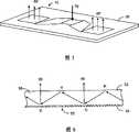
Yaakov Amitai和Asher Friesem的PCT专利申请WO 99/52002“Holographic optical Devices”以及Yaakov Amitai和Asher Friesem的美国专利US 6,580,529“Holographic optical Devices”公开了一种放大虚拟显示器的出瞳的方法。所公开的方法使用三个连续全息光学单元(HOE)来放大出瞳。具体而言,HOE是布置在如图1中所示平面型透光衬底6上的衍射光栅单元。如图所示,来自图像源2的光在设置于衬底6的一侧上的第一HOE或者H1之上入射。来自耦合到衬底6的H1的光被引向第二HOE或者H2,其中光的分布在一个方向上被扩展。H2也将被扩展的光分布重新引向第三HOE或者H3,其中光分布进一步在另一方向上被扩展。全息单元可以在衬底6的任一侧上。H3也把扩展的光分布从H3设置于其上的衬底表面重新引向外界。如图1中所示的光学系统作为一种近似地维持光束大体方向的光束扩展设备来工作。这样的设备也称为出瞳扩展器(EPE)。PCT Patent Application WO 99/52002 "Holographic Optical Devices" by Yaakov Amitai and Asher Friesem and US Patent US 6,580,529 "Holographic Optical Devices" by Yaakov Amitai and Asher Friesem disclose a method of enlarging the exit pupil of a virtual display. The disclosed method uses three consecutive holographic optical elements (HOEs) to enlarge the exit pupil. Specifically, the HOE is a diffraction grating unit arranged on a planar light-transmitting substrate 6 as shown in FIG. 1 . As shown, light from image source 2 is incident upon a first HOE or H1 disposed on one side of substrate 6 . Light from H1 coupled to the substrate 6 is directed towards the second HOE or H2, where the distribution of the light is expanded in one direction. H2 also redirects the expanded light distribution towards a third HOE or H3, where the light distribution is further expanded in the other direction. The holographic elements can be on either side of the substrate 6 . H3 also redirects the extended light distribution from the substrate surface on which H3 is disposed to the outside world. The optical system as shown in Figure 1 operates as a beam expansion device that approximately maintains the general direction of the beam. Such devices are also known as exit pupil expanders (EPE).
在EPE中,出口光束相对于输入光束的能量取决于相邻光学单元之间的耦合。由于图像源的能量输出有限,所以希望实现相邻光学单元之间的高耦合效率。In EPE, the energy of the exit beam relative to the input beam depends on the coupling between adjacent optical elements. Due to the limited energy output of the image source, it is desirable to achieve high coupling efficiency between adjacent optical units.
发明内容Contents of the invention
本发明的目的在于改进在出瞳扩展器中比如衍射光学单元这样的两个光学单元之间的光学耦合。这一目的可以通过使用具有定位在特定方向上的光栅线的衍射光学单元来实现,其作为放置在输入光学单元和离开光学单元之间的光学耦合器。特别地,该光学耦合器的光栅线定位为与输入光学单元和离开光学单元的光栅线呈60度。The object of the invention is to improve the optical coupling between two optical units, such as diffractive optical units, in an exit pupil expander. This object can be achieved by using a diffractive optical unit with grating lines positioned in a specific direction as an optical coupler placed between the input optical unit and the exit optical unit. In particular, the grating lines of the optical coupler are positioned at 60 degrees to the input optical unit and the grating lines exiting the optical unit.
由此,本发明的第一方面提供一种光学设备,包括:Thus, a first aspect of the present invention provides an optical device comprising:
光学材料的衬底,具有第一侧面和相对的第二侧面;a substrate of optical material having a first side and an opposite second side;
第一衍射单元,设置于衬底上,用于接收光束;The first diffraction unit is arranged on the substrate and is used to receive the light beam;
第二衍射单元,相关于第一衍射单元设置于衬底上;以及The second diffraction unit is disposed on the substrate relative to the first diffraction unit; and
中间衍射单元,设置于第一衍射单元与第二衍射单元之间,其中The intermediate diffraction unit is arranged between the first diffraction unit and the second diffraction unit, wherein
接收光束的至少一部分在第一衍射单元中衍射,以便基本上在第一表面和第二表面内在入射方向上将衍射光分量提供给中间衍射单元,以及at least a portion of the received light beam is diffracted in the first diffractive unit to provide diffracted light components in the direction of incidence substantially within the first surface and the second surface to the intermediate diffractive unit, and
在中间衍射单元中的衍射光分量的至少一部分基本上在第一表面与第二表面之间耦合到第二衍射单元,以便允许耦合衍射光分量的至少一部分通过在第二衍射单元中的衍射来退出衬底,其中中间衍射单元具有由沿着图案方向的基本上线性的单元组成的基本上周期性的图案以便产生圆锥衍射。At least a part of the diffracted light component in the intermediate diffractive unit is coupled to the second diffractive unit substantially between the first surface and the second surface, so as to allow at least a part of the coupled diffracted light component to be extracted by diffraction in the second diffractive unit Exit the substrate where the intermediate diffractive elements have a substantially periodic pattern consisting of substantially linear elements along the pattern direction to produce conical diffraction.
根据本发明的第一方面,中间衍射单元具有由沿着图案方向的基本上线性的单元组成的基本上周期的图案,使得向中间衍射单元提供的衍射光分量的入射方向在相对于图案方向而言的20度与40度的角范围内。According to a first aspect of the present invention, the intermediate diffractive unit has a substantially periodic pattern consisting of substantially linear units along the pattern direction, so that the incident direction of the diffracted light component provided to the intermediate diffractive unit is in a direction relative to the pattern direction. Within the angular range of 20 degrees and 40 degrees.
根据本发明的第一方面,该光学设备还包括:According to the first aspect of the present invention, the optical device also includes:
第三衍射单元,与第二衍射单元相间隔地相关于第一衍射单元设置于衬底上;以及a third diffraction unit disposed on the substrate relative to the first diffraction unit at a distance from the second diffraction unit; and
又一中间衍射单元,设置于第一衍射单元与第二衍射单元之间,其中Another intermediate diffraction unit is arranged between the first diffraction unit and the second diffraction unit, wherein
接收光束的至少一部分在第一衍射单元中衍射,以便在第一表面和第二表面内在入射方向上将衍射光分量提供给该又一中间衍射单元,以及at least a portion of the received light beam is diffracted in the first diffractive unit to provide diffracted light components in the direction of incidence within the first surface and the second surface to the further intermediate diffractive unit, and
在该又一中间衍射单元中的衍射光分量的至少一部分基本上在第一表面与第二表面之间耦合到第三衍射单元,以便允许耦合衍射光分量的至少一部分通过在第三衍射单元中的衍射来退出衬底,其中该又一中间衍射单元具有由沿着图案方向的基本上线性的单元组成的基本上周期的图案,使得向又一中间衍射单元提供的衍射光分量的入射方向在相对于图案方向而言的50度与70度的角范围内。At least a part of the diffracted light component in the further intermediate diffractive unit is coupled to a third diffractive unit substantially between the first surface and the second surface, so as to allow at least a part of the coupled diffracted light component to pass through the third diffractive unit to exit the substrate, wherein the further intermediate diffractive unit has a substantially periodic pattern consisting of substantially linear units along the pattern direction, such that the incident direction of the diffracted light component provided to the further intermediate diffractive unit is at Within the angular range of 50 degrees and 70 degrees relative to the direction of the pattern.
根据本发明的第一方面,通过第一表面在第一衍射单元中接收该接收光束,并且耦合衍射光分量的至少一部分通过第一表面或者第二表面退出衬底。According to a first aspect of the invention, the received light beam is received in the first diffractive unit through the first surface, and at least a part of the coupled diffracted light component exits the substrate through the first surface or the second surface.
根据本发明的第一方面,中间衍射单元包括形成周期性图案的多个槽。According to the first aspect of the present invention, the intermediate diffractive unit includes a plurality of grooves forming a periodic pattern.
根据本发明的第一方面,第一衍射单元具有由沿着与入射方向基本上垂直的图案方向的多个线性单元组成的周期性的图案,而第二衍射单元具有由沿着与入射方向基本上垂直的图案方向的多个线性的单元组成的周期性的图案。According to the first aspect of the present invention, the first diffractive unit has a periodic pattern consisting of a plurality of linear units along a pattern direction substantially perpendicular to the incident direction, while the second diffractive unit has a pattern composed of A periodic pattern composed of multiple linear units in the vertical direction of the pattern.
另外根据本发明的第一方面,光束可以通过波矢量kin来限定,而第一衍射单元可以包含具有周期d的周期性线;第二衍射单元可以包含具有周期d的更多周期性线,其中更多周期性线平行于第一衍射单元的周期性线; 中间衍射单元可以包含具有通过范围0.9d/2cosρ至1.1 d/2cosρ来限定的周期的另外更多周期性线,其中ρ是周期性线与另外更多周期性线之间的角度;以及耦合衍射光分量的至少一部分可以通过在第二衍射单元中的衍射来退出衬底,由此提供通过具有与光束的波矢量kin完全相同的方向的又一波矢量kout来限定的输出光束。另外,衍射光分量的至少一部分可以在向第二衍射单元提供衍射光分量的至少一部分之前进一步从中间衍射单元偶数次地衍射成一阶。另外,中间衍射单元可以仅支持反射零阶衍射模式和反射一阶衍射模式,或者衬底的折射率是n>λ/d,其中λ是输入光束的波长。另外,可以维持预定条件,该条件是中间衍射单元不支持二阶或者更高阶模式,或者该条件表达为
本发明的第二方面提供一种在光学设备中光学耦合的方法,该光学设备包括:A second aspect of the invention provides a method of optical coupling in an optical device comprising:
光学材料的衬底,具有第一表面和相对的第二表面;a substrate of optical material having a first surface and an opposite second surface;
第一衍射单元,设置于衬底上,用于接收光束,其中接收光束的至少一部分在第一衍射单元中衍射以便提供衍射光分量;以及a first diffraction unit disposed on the substrate for receiving a light beam, wherein at least a portion of the received light beam is diffracted in the first diffraction unit to provide a diffracted light component; and
第二衍射单元,相关于第一衍射单元设置于衬底上,以便允许衍射光分量的至少一部分通过在第二衍射单元中的衍射来退出衬底。该方法包括:A second diffractive unit is arranged on the substrate in relation to the first diffractive unit so as to allow at least a portion of the diffracted light components to exit the substrate by diffraction in the second diffractive unit. The method includes:
在第一衍射单元与第二衍射单元之间设置中间衍射单元,以便允许衍射光分量的一部分在入射方向在第一表面与第二表面之间进入中间衍射单元,其中中间衍射单元具有由沿着图案方向的基本上线性的单元组成的基本上周期性的图案以便产生圆锥衍射。An intermediate diffraction unit is arranged between the first diffraction unit and the second diffraction unit, so that a part of the diffracted light component is allowed to enter the intermediate diffraction unit between the first surface and the second surface in the incident direction, wherein the intermediate diffraction unit has A substantially periodic pattern of substantially linear elements of pattern direction so as to produce conical diffraction.
根据本发明的第二方面,中间衍射单元具有由沿着图案方向的基本上线性的单元组成的基本上周期性的图案,使得衍射光分量的入射方向在相对于图案方向而言的20度与40度的角范围内。According to a second aspect of the present invention, the intermediate diffractive element has a substantially periodic pattern consisting of substantially linear elements along the pattern direction such that the incident direction of the diffracted light component is within 20 degrees with respect to the pattern direction and within an angle of 40 degrees.
根据本发明的第二方面,该光学设备还包括:第三衍射单元,与第二设备相间隔地相关于第一衍射单元设置于衬底上,以便允许衍射光分量的至少一部分基本上通过在第三衍射单元中的衍射来退出衬底。该方法还包括:According to a second aspect of the present invention, the optical device further comprises: a third diffractive unit disposed on the substrate in relation to the first diffractive unit at a distance from the second device, so as to allow at least a part of the diffracted light component to pass substantially through the Diffraction in the third diffraction unit to exit the substrate. The method also includes:
在第一衍射单元与第三衍射单元之间设置又一中间衍射单元,以便允许衍射光分量的一部分在入射方向在第一表面与第二表面中间进入又一中间衍射单元,其中又一中间衍射单元具有由沿着图案方向的基本上线的性单元组成的基本上周期性的图案,使得衍射光分量的入射方向在相对于图案方向而言的50度与70度的角范围内。Another intermediate diffraction unit is set between the first diffraction unit and the third diffraction unit, so as to allow a part of the diffracted light component to enter another intermediate diffraction unit in the middle of the first surface and the second surface in the incident direction, wherein another intermediate diffraction unit The cells have a substantially periodic pattern of substantially linear cells along the pattern direction such that the incident direction of the diffracted light components is within an angular range of 50 degrees and 70 degrees relative to the pattern direction.
根据本发明的第二方面,第一衍射单元具有由沿着第一图案方向的基本上线性的单元组成的基本上周期性的图案,而第二衍射单元具有由沿着与第一图案方向基本上平行的第二图案方向的基本上线性单元组成的基本上周期性的图案。According to a second aspect of the present invention, the first diffractive element has a substantially periodic pattern consisting of substantially linear elements along the first pattern direction, and the second diffractive element has a substantially periodic pattern composed of substantially linear elements along the first pattern direction. A substantially periodic pattern consisting of substantially linear units parallel to the second pattern direction.
另外根据本发明的第二方面,光束可以通过波矢量kin来限定,而第一衍射单元可以包含具有周期d的周期性线;第二衍射单元可以包含具有周期d的更多周期性线,其中更多周期性线平行于第一衍射单元的周期性线;中间衍射单元可以包含具有通过范围0.9d/2cosρ至1.1d/2cosρ来限定的周期的另外更多周期性线,其中ρ是周期性线与另外更多周期性线之间的角度;以及耦合衍射光分量的至少一部分可以通过在第二衍射单元中的衍射来退出衬底,由此提供通过具有与光束的波矢量kin完全相同的方向的又一波矢量kout来限定的输出光束。另外,衍射光分量的至少一部分可以在向第二衍射单元提供衍射光分量的至少一部分之前进一步从中间衍射单元偶数次地衍射成一阶。Also according to the second aspect of the invention, the light beam can be defined by the wave vectorkin , while the first diffractive unit can contain periodic lines with period d; the second diffractive unit can contain more periodic lines with period d, where the more periodic lines are parallel to the periodic lines of the first diffractive unit; the intermediate diffractive unit may contain further more periodic lines with a period defined by the range 0.9d/2cosρ to 1.1d/2cosρ, where p is the period The angle between the linear line and another more periodic line; and at least a part of the coupled diffracted light component can exit the substrate by diffraction in the second diffraction unit,thereby providing Another wave vector kout of the same direction to define the output beam. In addition, at least a part of the diffracted light component may be further diffracted into the first order an even number of times from the intermediate diffractive unit before supplying at least a part of the diffracted light component to the second diffractive unit.
本发明的第三方面提供一种电子设备,包括:A third aspect of the present invention provides an electronic device, comprising:
数据处理单元;data processing unit;
光学引擎,可操作地连接到数据处理单元,用于从数据处理单元接收图像数据;an optical engine operatively connected to the data processing unit for receiving image data from the data processing unit;
显示器设备,可操作地连接到光学引擎,用于基于图像数据形成图像;以及a display device operatively connected to the optical engine for forming an image based on the image data; and
出瞳延伸器,包括:Exit pupil extenders, including:
光学材料的衬底,具有第一表面和相对的第二表面;a substrate of optical material having a first surface and an opposite second surface;
第一衍射单元,设置于衬底上,用于接收光束;The first diffraction unit is arranged on the substrate and is used to receive the light beam;
第二衍射单元,相关于第一衍射单元设置于衬底上;以及The second diffraction unit is disposed on the substrate relative to the first diffraction unit; and
中间衍射单元,设置于第一衍射单元和第二衍射单元之间,其中The intermediate diffraction unit is arranged between the first diffraction unit and the second diffraction unit, wherein
接收光束的至少一部分在第一衍射单元中衍射,以便基本上在第一表面和第二表面内在入射方向上将衍射光分量提供给中间衍射单元,以及at least a portion of the received light beam is diffracted in the first diffractive unit to provide diffracted light components in the direction of incidence substantially within the first surface and the second surface to the intermediate diffractive unit, and
在中间衍射单元中的衍射光分量的至少一部分基本上在第一表面与第二表面之间耦合到第二衍射单元,以便允许耦合衍射光分量的至少一部分通过在第二衍射单元中的衍射来退出衬底,其中中间衍射单元具有由沿着图案方向的基本上线性单元组成的基本上周期性的图案以便产生圆锥衍射。At least a part of the diffracted light component in the intermediate diffractive unit is coupled to the second diffractive unit substantially between the first surface and the second surface, so as to allow at least a part of the coupled diffracted light component to be extracted by diffraction in the second diffractive unit Exit the substrate, wherein the intermediate diffractive elements have a substantially periodic pattern consisting of substantially linear elements along the pattern direction so as to produce conical diffraction.
根据本发明的第三方面,在圆锥衍射中的角度介于50度与70度之间,而中间衍射单元具有由沿着图案方向的基本上线性的单元组成的基本上周期性的图案,使得向中间衍射单元提供的衍射光分量的入射方向在相对于图案方向而言的20度与40度的角范围内。According to a third aspect of the invention, the angle in conical diffraction is between 50 and 70 degrees, and the intermediate diffractive elements have a substantially periodic pattern consisting of substantially linear elements along the pattern direction such that The incident direction of the diffracted light component provided to the intermediate diffraction unit is within an angle range of 20 degrees and 40 degrees with respect to the pattern direction.
根据本发明的第三方面,该光学设备还包括:According to a third aspect of the present invention, the optical device further includes:
第三衍射单元,与第二衍射单元相间隔地相关于第一衍射单元设置于衬底上;以及a third diffraction unit disposed on the substrate relative to the first diffraction unit at a distance from the second diffraction unit; and
又一中间衍射单元,设置于第一衍射单元与第三衍射单元之间,其中Another intermediate diffraction unit is arranged between the first diffraction unit and the third diffraction unit, wherein
接收光束的至少一部分在第一衍射单元中衍射,以便在第一表面和第二表面内在入射方向上将衍射光分量提供给又一中间衍射单元,以及at least a portion of the received light beam is diffracted in the first diffractive unit to provide diffracted light components in the direction of incidence within the first surface and the second surface to a further intermediate diffractive unit, and
在又一中间衍射单元中的衍射光分量的至少一部分基本上在第一表面与第二表面之间耦合到第三衍射单元,以便允许耦合衍射光的至少一部分通过在第三衍射单元中的衍射来退出衬底,其中又一中间衍射单元具有由沿着图案方向的基本上线性的单元组成的基本上周期性的图案,使得向又一中间衍射单元提供的衍射光分量的入射方向在相对于图案方向而言的50度与70度的角范围内。At least a part of the diffracted light component in the further intermediate diffractive unit is coupled to a third diffractive unit substantially between the first surface and the second surface, so as to allow at least a part of the coupled diffracted light to pass through the diffraction in the third diffractive unit To exit the substrate, wherein another intermediate diffractive unit has a substantially periodic pattern consisting of substantially linear units along the pattern direction, so that the incident direction of the diffracted light component provided to the further intermediate diffractive unit is relative to In the angle range of 50 degrees and 70 degrees in terms of pattern direction.
根据本发明的第三方面,该电子设备可以是便携设备,比如移动电话、个人数字助理(PDA)、通信器、便携因特网设备、手持计算机、数字视频和静止相机、可佩戴式计算机、计算机游戏设备、用于观看的专用一睹为快产品和其它便携电子设备。然而,根据本发明的出瞳延伸器也可以使用于非便携设备中,比如游戏设备、售货机、整经机和家电如烤箱、微波炉和其它家电以及其它非便携设备中。According to a third aspect of the present invention, the electronic device may be a portable device such as a mobile phone, a personal digital assistant (PDA), a communicator, a portable Internet device, a hand-held computer, a digital video and still camera, a wearable computer, a computer game devices, special peek-a-boo products for viewing, and other portable electronic devices. However, the exit pupil extender according to the present invention can also be used in non-portable equipment such as gaming equipment, vending machines, warping machines and household appliances such as ovens, microwave ovens and other household appliances and other non-portable equipment.
另外根据本发明的第三方面,光束可以通过波矢量kin来限定,而第一衍射单元可以包含具有周期d的周期性线;第二衍射单元可以包含具有周期d的更多周期性线,其中更多周期性线平行于第一衍射单元的周期性线;中间衍射单元可以包含具有通过范围0.9d/2cosρ至1.1d/2cosρ来限定的周期的另外更多周期性线,其中ρ是周期性线与另外更多周期性线之间的角度;以及耦合衍射光分量的至少一部分可以通过在第二衍射单元中的衍射来退出衬底,由此提供通过具有与光束的波矢量kin完全相同的方向的又一波矢量kout来限定的输出光束。另外,衍射光分量的至少一部分可以在向第二衍射单元提供衍射光分量的至少一部分之前进一步从中间衍射单元偶数次地衍射成一阶。Also according to the third aspect of the invention, the light beam can be defined by the wave vectorkin , and the first diffractive unit can contain periodic lines with period d; the second diffractive unit can contain more periodic lines with period d, where the more periodic lines are parallel to the periodic lines of the first diffractive unit; the intermediate diffractive unit may contain further more periodic lines with a period defined by the range 0.9d/2cosρ to 1.1d/2cosρ, where p is the period The angle between the linear line and another more periodic line; and at least a partof the coupled diffracted light component can exit the substrate by diffraction in the second diffraction unit, thereby providing Another wave vector kout of the same direction to define the output beam. In addition, at least a part of the diffracted light component may be further diffracted into the first order an even number of times from the intermediate diffractive unit before supplying at least a part of the diffracted light component to the second diffractive unit.
在阅读与图2-图10相结合的描述时,本发明将变得明显。The invention will become apparent when reading the description in conjunction with FIGS. 2-10 .
附图说明Description of drawings
图1是示出了现有技术中一种使用三个衍射单元的出瞳扩展器的示意性表示图;FIG. 1 is a schematic representation showing a pupil expander using three diffraction units in the prior art;
图2是示出了根据本发明的出瞳延伸器的顶视图的示意性表示图;Figure 2 is a schematic representation showing a top view of an exit pupil extender according to the present invention;
图3是示出了根据本发明的出瞳延伸器的等距图的示意性表示图;Figure 3 is a schematic representation showing an isometric view of an exit pupil extender according to the present invention;
图4是示出了根据本发明在中间衍射光学单元中光栅线的取向的示意性表示图;4 is a schematic representation showing the orientation of grating lines in an intermediate diffractive optical unit according to the present invention;
图5是示出了根据本发明的出瞳延伸器的另一实施例的示意性表示图;Figure 5 is a schematic representation showing another embodiment of an exit pupil extender according to the present invention;
图6是示出了衍射光学单元中的典型反射和衍射的示意性表示图;Figure 6 is a schematic representation showing typical reflections and diffractions in a diffractive optical unit;
图7是示出了具有虚拟显示器系统的电子设备的示意性表示图;Figure 7 is a schematic representation showing an electronic device with a virtual display system;
图8是示出了根据本发明的广义2D出瞳扩展器的几何形状的示意性表示图;Figure 8 is a schematic representation showing the geometry of a generalized 2D exit pupil expander according to the present invention;
图9a和图9b是根据本发明在中间衍射光栅中传播的光束的示意性表示图(分别是侧视图和顶视图);以及Figures 9a and 9b are schematic representations (side and top views, respectively) of a light beam propagating in an intermediate diffraction grating according to the present invention; and
图10是根据本发明的中间衍射光栅的布局的示意性表示图。Fig. 10 is a schematic representation of the layout of an intermediate diffraction grating according to the invention.
具体实施方式Detailed ways
在根据本发明的出瞳延伸器(EPE)10中具有由光学材料制成的衬底20。如图2中所示,在衬底20上有一个输入光学单元30和一个或者两个出口光学单元50。EPE 10也具有各自设置于输入光学单元30与出口光学单元50、50’之一之间的一个或者两个中间光学耦合器40、40’。耦合器40、40’作为出瞳延伸部件来使用。光学单元30、50、50’和耦合器40、40’例如是衍射光学单元(DOE)。各DOE具有用于衍射目的的多个光栅线。如图所示,光学单元30具有多个光栅线32;光学单元40(40’)具有多个光栅线42,而光学单元50(50’)具有多个光栅线52。In the exit pupil extender (EPE) 10 according to the invention there is a
图3是示出了在输入光束70与两个退出光束80、80’之间的关系的等距图。如图所示,衬底20具有第一侧22和第二侧24。输入光束70在衬底20的一侧上进入EPE 10,而退出光束80、80’在与输入光束基本上平行的方向上在衬底20的不同侧上退出EPE 10。Figure 3 is an isometric diagram showing the relationship between the
如图2中所示,DOE 30和50(50’)中的光栅线32和52基本上平行于Y轴。为了DOE 40(40’)像光束延伸器一样起作用并且优化它的效率,耦合器DOE 40(40’)中的光栅线如图4中所示相对于Y轴基本上成60度的角。于是,进入DOE 40(40’)的一侧的光陷入第一侧22与第二侧24之间的光栅区域中,直至它从DOE 40(40’)的另一侧显现出来。另外,DOE 40(40’)的形状被设计成使得在输出端处,离开光栅区域的射线如图3中所示基本上平行于X轴。As shown in FIG. 2, the
根据本发明的一个实施例,所有DOE 30、40(40’)和50(50’)中的光栅周期基本上相同。然而,尽管DOE 30和50(50’)具有同一周期,仍然允许DOE 40略微偏离于这些周期而不扰乱EPE系统的运作。不过各光栅具有根据它的功能而优化的独有光栅分布。DOE30和DOE 40(40’)通常具有深的分布和恰当的填充比。According to one embodiment of the invention, the grating periods are substantially the same in all
如图3中所示,当EPE 10用来扩张在DOE 30之上入射的光束70时,光束70由于衬底20的一侧上的总内部反射(TIR)(如果DOE 30设置于上侧22上,则TIR出现在下侧24上)而基本上沿着方向72(72’)朝着DOE 40(40’)衍射和反射。光束从DOE 40(40’)进一步衍射到相对于方向72(72’)基本上成60度圆锥角的方向。在衬底20的下侧中的TIR之后,光束再次与光栅40(40’)会合、然后在平行于方向72(72’)的方向上再次衍射。最后,在一些连续步骤之后,光束基本上沿着与方向72(72’)基本上相同的方向74(74’)进入DOE 50(50’)。重要的是保证光束与光栅40(40’)会合偶数次。否则光束没有恰好地在正确的方向进入DOE 50(50’)。最后,光束作为退出光束80、80’退出DOE 50、50’。然而应当注意,退出光束80、80’的横截面大于输入光束70的横截面,因为输入光束在DOE中在Y轴和X轴中都被扩展。如图3中所示,进入DOE 40的光束的入射角基本上沿着基本上在XZ平面中的方向72。方向72可以根据圆锥光栅等式来计算,而一般在实践情况下,方向72上的光束没有完全地在XZ平面中行进而以某些度数偏离于该平面。As shown in FIG. 3, when the
图4示出了DOE 40中光栅线42的取向。如上所述,光栅线42相对于Y轴基本上成60度的角。由此,光栅线42相对于入射方向72基本上成60度圆锥角(见图3)。然而,圆锥角可以偏离于60度,只要在衍射中存在仅两个反射衍射模式:零阶和一阶。应当注意,在圆锥衍射中光束一般不垂直于光栅线。圆锥角相对于垂直方向来限定。这一条件取决于传入光束角(70)、光栅周期以及材料的折射率。这一可接受的角空间必须使用圆锥衍射公式根据情况来计算。这一可接受的角空间通常如此之大以至于系统在多数实践情况、甚至宽视野情况下中起作用。如前所述,有必要的是光束与光栅40(40’)相遇偶数次。因此,DOE 40(40’)的离开边沿的角必须使得满足这一条件。这一角度可以根据圆锥衍射公司和传入光束的角展度来计算。一般而言,DOE 40(40’)的离开边沿由此相对于Y轴形成略大于30度的角。DOE 40(40’)通常是二元型光栅,而在本发明中描述的几何形状中,第一衍射阶的衍射效率可能高达90%。另外,可以用恰当的填充比来调节光栅效率以便与极化无关。FIG. 4 shows the orientation of the
DOE 40’基本上是DOE 40的镜像。由此,光栅线42’的取向类似于光栅线42的取向。
如图3中所示,输入光束70在EPE 10的一侧上进入DOE 30,而退出光束80、80’在EPE 10的另一侧上离开DOE 50、50’。应当注意,EPE 10中衍射光栅的布置一般使得退出光束80、80’也在与进入EPE 10的输入光束70相同的一侧上退出EPE 10,如图5中所示。As shown in Figure 3, the
在本领域中已知,退出光束80、80’中与输入光束70相比而言的光束扩展部分地归因于各种DOE中的不同尺度和形状以及部分地归因于多次衍射和总内部反射(TIR)。如图6中所示,传入光束在不同位置R通过TIR来反射而在衍射位置D通过光栅线52来衍射,获得退出光束80。It is known in the art that the beam expansion in the exit beams 80, 80' compared to the
EPE 10可以使用于便携设备100中,比如移动电话、个人数字助理(PDA)、通信器、便携因特网设备、手持计算机、数字视频和静止相机、可佩戴式计算机、计算机游戏设备、用于观看的专用一睹为快式(bring-to-the-eye)产品和其它便携电子设备。如图7中所示,便携设备100具有用以容纳通信单元212的壳体210,该通信单元用于从外部设备(未示出)接收信息和发送信息到该外部设备。便携设备100也具有用于处理所接收的信息和所发送的信息的控制和处理单元214以及用于观看的虚拟显示器系统230。虚拟显示器系统230包括微显示器或者图像源192和光学引擎190。控制和处理单元214可操作地连接到光学引擎190以提供图像数据给图像源192从而在其上显示图像。根据本发明的EPE 10可以光学地链接到光学引擎190。The
应当注意,各光学单元30、40、40’、50、50’可以是具有光栅线的衍射光学单元或者具有干涉条纹的全息衍射光学单元(HOE)。顾名思义,全息衍射单元是以全息方式产生的,其中至少两个相干光束用来产生条纹。与此不同的是,衍射光学单元可以用机械或者化学方式来产生。It should be noted that each
本发明的目的在于实现EPE中各种DOE之间的高效光学耦合,而在尺寸和形状上设置DOE并且将DOE布置用于退出瞳孔扩展。本发明的EPE的应用不限于虚拟显示器。根据本发明在平面型波导(衬底20)中的选择性反射控制也可以使用于任何如下应用中,在该应用中需要一个或者多个方向上的光束扩展并且使用不同波长的光。衍射单元事实上是用于将光耦合到平面型波导中的光学耦合器和光调制器设备。由此,如图2至图6中所示的EPE 10可以视为一种包括平面型波导和多个光学耦合器(或者光调制器设备)的光学设备,这些光学耦合器相邻于波导来设置或者设置于波导上用于光耦合和操纵目的。It is an object of the present invention to achieve efficient optical coupling between the various DOEs in the EPE, while sizing and shaping the DOEs and arranging the DOEs for exit pupil dilation. The application of the EPE of the present invention is not limited to virtual displays. Selective reflection control in planar waveguides (substrate 20) according to the present invention can also be used in any application where beam expansion in one or more directions is required and light of different wavelengths is used. The diffractive unit is in fact an optical coupler and light modulator device for coupling light into a planar waveguide. Thus, the
如图7中描绘的图像源192可以是顺序彩色LCOS(硅上液晶)设备、OLED(有机发光二极管)阵列、MEMS(微电机电系统)设备或者在透射、反射或者放射模式下操作的任何其它适当微显示器设备。
另外,电子设备100可以是便携设备如移动电话、个人数字朱里(PDA)、通信器、便携因特网设备、手持计算机、数字视频和静止相机、可佩戴式计算机、计算机游戏设备、用于观看的专用一睹为快产品和其它便携电子设备。然而,根据本发明的出瞳延伸器也可以使用于非便携设备如游戏设备、售货机、整经机(band-o-matic)和家电如烤箱、微波炉和其它家电以及其它非便携设备中。Additionally,
由此,虽然已经参照其优选实施例来描述本发明,但是本领域技术人员将理解,可以在不脱离本发明的范围情况下做出在其形式和细节上的前述和各种其它变化、省略及变更。Thus, while the present invention has been described with reference to preferred embodiments thereof, it will be understood by those skilled in the art that the foregoing and various other changes in form and details, omissions and modifications may be made without departing from the scope of the invention. and changes.
本发明的又一目的在于提供一种在光学衬底上使用多个衍射单元以便扩展用于观看的电子设备的显示器的出瞳的通用衍射光学方法。Yet another object of the present invention is to provide a general diffractive optics method using a plurality of diffractive elements on an optical substrate in order to extend the exit pupil of a display of an electronic device for viewing.
根据本发明的一个实施例,这一方法可以用于光学设备中的光学耦合,而它的特征在于扩展在输出光束中提供的输入光束的出瞳,其中该光学设备包括:光学材料的衬底(或者光学衬底),具有第一表面和相对的第二表面;第一(耦合内)衍射单元,设置于衬底上,用于接收通过波矢量kin限定的输入光束(或者输入光线束)并且包含具有周期d的周期性线;第二(耦合出)衍射单元,相关于第一衍射单元设置于衬底上并且包含与第一衍射单元的线基本上平行的具有周期d的更多周期性线;以及中间(扩展)衍射单元,相邻于第一和第二衍射单元来设置,其周期性线在光学衬底的平面中相对于第一和第二衍射单元的线成角度ρ。According to an embodiment of the present invention, this method can be used for optical coupling in an optical device characterized by expanding the exit pupil of the input beam provided in the output beam, wherein the optical device comprises: a substrate of optical material (or an optical substrate) having a first surface and an opposite second surface; a first (in-coupling) diffraction unit disposed on the substrate for receiving an input light beam (or an input light beam) defined by a wave vector kin ) and contains periodic lines with period d; a second (coupling-out) diffractive unit, arranged on the substrate relative to the first diffractive unit and comprising more lines with period d substantially parallel to the lines of the first diffractive unit a periodic line; and an intermediate (extended) diffractive element, disposed adjacent to the first and second diffractive elements, the periodic line of which is at an angle p with respect to the line of the first and second diffractive element in the plane of the optical substrate .
另外,接收的光束的至少一部分在第一衍射单元中被衍射以便基本上在第一和第二表面内将具有波矢量k0的衍射光分量提供给中间衍射单元(例如经历总内部反射)。另外,在中间衍射单元中的衍射光分量的至少一部分再次被衍射成具有波矢量k2的第一衍射阶、并且基本上在第一与第二表面之间最终被耦合到第二衍射单元(同样例如经历总内部反射)以便允许所耦合的衍射光分量的至少一部分通过在第二衍射单元中的衍射来退出衬底,由此提供通过又一波矢量kout限定的输出光束。通常,第二衍射单元也生成另一输出光束,该波矢量就衬底表面而言是波矢量kout的镜像。由于这一波矢量在其它方面与波矢量kout相同而在实际应用中它被有意地阻尼到低值,因此并不与波矢量kout有更多不同地来考虑它。Additionally, at least a portion of the received light beam is diffracted in the first diffractive unit to provide a diffracted light component having wavevectork0 to an intermediate diffractive unit substantially within the first and second surfaces (eg undergoing total internal reflection). In addition, at least a part of the diffracted light component in the intermediate diffractive element is diffracted again into the first diffraction order with wave vector k2 and is finally coupled to the second diffractive element ( Also eg undergoes total internal reflection) in order to allow at least a part of the coupled diffracted light components to exit the substrate by diffraction in the second diffractive unit, thereby providing anoutput beam defined by a further wave vector kout. Typically, the second diffractive unit also generates a further output beam whose wave vector is the mirror image of the wave vector kout with respect to the substrate surface. Since this wave vector is otherwise identical to the wave vector kout and in practice it is intentionally damped to low values, it is not considered any more different than the wave vector kout .
根据本发明的一个实施例,中间衍射光栅包含更多周期性线,其中在第一衍射单元的周期性线与这些更多周期性线之间的角度(或者旋转角)为ρ,并且这更多周期性线的周期d’给定如下:According to one embodiment of the invention, the intermediate diffraction grating contains more periodic lines, wherein the angle (or rotation angle) between the periodic lines of the first diffractive unit and these more periodic lines is ρ, and this is more The period d' of a polyperiodic line is given as follows:
0.9d/2cosρ<d′<1.1d/2cosρ (1).0.9d/2cosρ<d′<1.1d/2cosρ (1).
根据本发明的一个实施例,在向第二衍射单元提供衍射光分量的所述至少一部分之前,光分量在中间衍射单元上入射和衍射(例如衍射成一阶)偶数次。在中间衍射单元上偶数次衍射的事实如下文证实的那样意味着又一波矢量k2具有与在适当的操作条件下(即系统在几何形状上是准确的)从具有波矢量kin的输入光束生成的波矢量k0完全相同的方向。According to an embodiment of the invention, the light component is incident and diffracted (eg into a first order) on the intermediate diffractive unit an even number of times before providing said at least part of the diffracted light component to the second diffractive unit. The fact that there is an even number of diffractions on the intermediate diffractive element means, asdemonstrated below, that a further wave-vector k hasthe same The wave vector k0 generated by the beam is in exactly the same direction.
另外,根据本发明的一个实施例,第一衍射单元、第二衍射单元或者中间衍射单元可以设置于光学衬底的第一表面上或者第二表面上。另外,根据本发明的一个实施例,第一衍射单元、第二衍射单元或者中间衍射单元可以使用平版印刷方法或者经典规则(具有不同的槽角和型面如二元、三角、正弦等)来制造的平面式衍射光栅。In addition, according to an embodiment of the present invention, the first diffraction unit, the second diffraction unit or the intermediate diffraction unit may be disposed on the first surface or the second surface of the optical substrate. In addition, according to an embodiment of the present invention, the first diffractive unit, the second diffractive unit or the intermediate diffractive unit can use lithographic methods or classical rules (with different groove angles and profiles such as binary, triangular, sinusoidal, etc.) Fabricated planar diffraction gratings.
根据本发明的广义方法提供了用于支持多样化旋转角使得系统在几何形状上准确(即波矢量kin和kout具有同一方向)的条件。第一衍射单元的周期使得它仅支持用来将光耦合到衬底中的零阶和一阶透射衍射模式。下文表明,如果中间衍射单元仅支持零阶和一阶反射模式而其它模式被禁止,则系统可以支持宽的旋转角范围0<ρ<70°以及更大范围。这意味着宽的圆锥入射角范围(至少在0与70°之间以及更大范围)可以通过中间衍射单元来支持(圆锥角是入射光的平面与垂直于周期性线的平面之间的角)。The generalized approach according to the invention provides conditions for supporting diverse rotation angles such that the system is geometrically accurate (ie wave vectors kin and kout have the same direction). The period of the first diffractive unit is such that it supports only the zeroth and first order transmissive diffractive modes for coupling light into the substrate. It is shown below that if the intermediate diffractive unit only supports zero-order and first-order reflection modes while other modes are disabled, the system can support a wide range of rotation angles 0<ρ<70° and beyond. This means that a wide range of conical incidence angles (at least between 0 and 70° and beyond) can be supported by intermediate diffractive elements (the cone angle is the angle between the plane of incident light and the plane perpendicular to the periodic line ).
图8示出了根据本发明的广义二维(2D)出瞳扩展器(EPE)300的几何形状的示意性表示图的多个例子之中特别的一个例子,该例子图示了上述通用衍射光学方法。图8示出了光学衬底(板)250的顶视图,该衬底具有设置于光学衬底250上的三个衍射单元:具有线周期d的第一(耦合内)衍射单元(耦合内衍射光栅)270、具有线周期d的第二衍射单元(耦合出衍射光栅)280(光栅270和280的周期性线是平行的)以及具有等式1所给定的线周期d’的中间(扩展)衍射单元(中间衍射光栅)260,其中线周期在光学衬底的平面中相对于第一和第二衍射单元270和280的线成角度ρ,如图8中所示。FIG. 8 shows a particular one of many examples of schematic representations of the geometry of a generalized two-dimensional (2D) exit pupil expander (EPE) 300 according to the present invention, which illustrates the above-mentioned general diffraction optical method. 8 shows a top view of an optical substrate (plate) 250 with three diffractive elements disposed on the optical substrate 250: a first (in-coupling) diffractive element (in-coupling diffractive) with a line period d grating) 270, a second diffractive unit (coupling out the diffraction grating) 280 with line period d (the periodic lines of
为了证实当光束从同一衍射光栅被两次衍射成一阶时保持这些角度,图9a和图9b示出了图8的光学衬底(透明板)250的示意性表示图(分别是侧视图和顶视图),其中中间衍射光栅260设置于该衬底的表面上。To demonstrate that these angles are maintained when the beam is diffracted twice into the first order from the same diffraction grating, Figures 9a and 9b show a schematic representation of the optical substrate (transparent plate) 250 of Figure 8 (side view and top view, respectively). view), wherein the
进入衍射光栅260的光束通过具有分量角(θ0,0)的波矢量k0来描述,这些分量角分别利用与光栅260的周期性线相垂直的板250的平面中的坐标轴和与光学衬底250的表面相垂直的轴来形成。角度(θ0,0)是来自耦合内光栅的一阶衍射的结果并且符合如下等式:A light beam entering the

其中已经选择+1透射阶以供考虑。对于其它模式-1则获得相似等式,但是模式符号相反。板250的折射率为n而对于空气而言折射率为1。光束被衍射成反射阶-1和0。对于衍射模式-1的角度,具有如下等式对:where the +1 transmission order has been chosen for consideration. Similar equations are obtained for the other mode-1, but with the opposite sign of the mode. The

该等式对限定了波矢量k1的分量,这些矢量通过利用与角度(θ0,0)相同的坐标轴而形成的角度(θ1,1)来描述。This pair of equations defines the components of the wave vector k1 described by the angle (θ1 , φ1 ) formed using the same coordinate axes as the angle (θ0 , φ0 ).
光束传播到上表面、然后在全内部反射之后到达下表面,在这里它再次与光栅260相遇。这一光束将被衍射光栅260衍射成反射阶1和0。反射阶1具有在板250内利用与角度(θ0,0)相同的坐标轴而形成的角度(θ2,2)。波矢量k2现在通过下式来限定:The light beam travels to the upper surface and then after total internal reflection to the lower surface where it meets the grating 260 again. This beam will be diffracted by the

从中可以看出θ0=θ2且0=2-ρ。It can be seen that θ0 =θ2 and φ0 = φ2 −ρ.
通过波矢量k2描述的光束然后被耦合到耦合出衍射光栅280。最后,耦合出光栅280将从板出来的光束耦合到通过角度(θrout,rout)描述的波矢量kout。等式如下:The beam described by wave vectork2 is then coupled into

这证实了当离开中间光栅区域的光束具有从光栅偶数次的一阶衍射时光束方向未变。这一原理在图10的例子中有进一步证实。This confirms that the beam direction is unchanged when the beam leaving the intermediate grating region has an even number of first order diffractions from the grating. This principle is further confirmed in the example in Figure 10.
为了保证在中间衍射光栅中恰好地有偶数次一阶衍射重新引向耦合出光栅,中间衍射光栅260的离开边沿必须相对于光栅线成某一角度,如图10中所示。针对该角度的关系如下:To ensure that exactly an even number of first order diffractions in the intermediate diffraction grating are redirected towards the outcoupling grating, the exit edge of the
角度(θin,in)在指定视野中是任何角度。Angle (θin , φin ) is any angle in the specified field of view.
为了保证在中间光栅中仅由零阶和一阶反射衍射,除了等式1所给定的线周期d’的范围之外还需要对光栅周期和旋转角设置一些要求。In order to ensure that only zero- and first-order reflections are diffracted in the intermediate grating, some requirements on the grating period and rotation angle need to be set in addition to the range of the line period d' given by Equation 1.
使用圆锥等式,可以计算在光学衬底250内部在与光学衬底250的表面相垂直的方向上的波矢量分量,这允许导出如下所示对于模式-1和0而言存在的条件:Using the cone equation, it is possible to calculate the wave vector components inside the
等式8的这一条件在所有实践情况下都有效,只要关注旋转角ρ即可。This condition of Equation 8 is valid in all practical cases, as long as the rotation angle ρ is concerned.
在中间衍射光栅中没有透射模式的条件是λ/d>1而它在所有实践情况下都有效。另一要求是在中间衍射光栅中应当不存在其它反射模式。仅考虑最低衍射模式即-2和+1就足够了,并且相应地获得如下条件:The condition for the absence of transmission modes in an intermediate diffraction grating is λ/d > 1 and it is valid in all practical cases. Another requirement is that there should be no other reflection modes in the intermediate diffraction grating. It is sufficient to consider only the lowest diffraction modes, i.e. -2 and +1, and correspondingly obtain the following conditions:
等式5描述的这一条件通常对于0<ρ<70°有效。这意味着宽的圆锥入射角范围(至少在0°与70°之间以及更大范围)可以得到中间衍射光栅的支持(圆锥角度是图8中的角度0+ρ),其中线周期d’的范围由等式1给定。由等式1给定的d’的范围在不同条件之下可能明显更宽。例如,可以表明,对于ρ=60°和°±12°的水平视野而言,d’的范围延伸到0.66d/2cosρ<d′<1.24d/2cosρ。This condition described by Equation 5 is generally valid for 0<ρ<70°. This means that a wide range of conic incidence angles (at least between 0° and 70° and beyond) can be supported by an intermediate diffraction grating (cone angle is the angle 0+ρ in Fig. 8), where the line period d ' range is given by Equation 1. The range of d' given by Equation 1 may be significantly wider under different conditions. For example, it can be shown that for a horizontal field of view of ρ = 60° and °±12°, the range of d' extends to 0.66d/2cosρ<d'<1.24d/2cosρ.
中间衍射光栅的效率达到约60°旋转角度的很高值,使得衍射效率对于TE和TM极化都相等。The efficiency of the intermediate diffraction grating reaches very high values around 60° rotation angle, making the diffraction efficiency equal for both TE and TM polarizations.
将理解到上述布置仅仅说明本发明原理的应用。在不脱离本发明的范围情况下可以由本领域技术人员做出许多修改和替选布置,而所附权利要求旨在于覆盖这样的修改和布置。It will be appreciated that the above arrangement is merely illustrative of the application of the principles of the invention. Numerous modifications and alternative arrangements may be devised by those skilled in the art without departing from the scope of the invention, and the appended claims are intended to cover such modifications and arrangements.
Claims (31)
Translated fromChineseApplications Claiming Priority (3)
| Application Number | Priority Date | Filing Date | Title |
|---|---|---|---|
| US11/011,481 | 2004-12-13 | ||
| US11/011,481US20060126181A1 (en) | 2004-12-13 | 2004-12-13 | Method and system for beam expansion in a display device |
| US11/202,653 | 2005-08-11 |
Publications (2)
| Publication Number | Publication Date |
|---|---|
| CN101103297Atrue CN101103297A (en) | 2008-01-09 |
| CN100492099C CN100492099C (en) | 2009-05-27 |
Family
ID=36583476
Family Applications (1)
| Application Number | Title | Priority Date | Filing Date |
|---|---|---|---|
| CN200580046877.3AActiveCN100492099C (en) | 2004-12-13 | 2005-12-12 | Universal diffractive optics method for expanding exit pupil |
Country Status (5)
| Country | Link |
|---|---|
| US (2) | US20060126181A1 (en) |
| JP (1) | JP5096160B2 (en) |
| CN (1) | CN100492099C (en) |
| DK (1) | DK1828832T3 (en) |
| IL (1) | IL183879A (en) |
Cited By (59)
| Publication number | Priority date | Publication date | Assignee | Title |
|---|---|---|---|---|
| CN107329261A (en)* | 2017-06-08 | 2017-11-07 | 东南大学 | A kind of head mounted display part based on holographical wave guide |
| CN108463767A (en)* | 2016-01-12 | 2018-08-28 | 奇跃公司 | Beam angle sensor in virtual/augmented reality systems |
| US10089516B2 (en) | 2013-07-31 | 2018-10-02 | Digilens, Inc. | Method and apparatus for contact image sensing |
| US10145533B2 (en) | 2005-11-11 | 2018-12-04 | Digilens, Inc. | Compact holographic illumination device |
| US10156681B2 (en) | 2015-02-12 | 2018-12-18 | Digilens Inc. | Waveguide grating device |
| US10185154B2 (en) | 2011-04-07 | 2019-01-22 | Digilens, Inc. | Laser despeckler based on angular diversity |
| US10209517B2 (en) | 2013-05-20 | 2019-02-19 | Digilens, Inc. | Holographic waveguide eye tracker |
| US10216061B2 (en) | 2012-01-06 | 2019-02-26 | Digilens, Inc. | Contact image sensor using switchable bragg gratings |
| US10234696B2 (en) | 2007-07-26 | 2019-03-19 | Digilens, Inc. | Optical apparatus for recording a holographic device and method of recording |
| US10241330B2 (en) | 2014-09-19 | 2019-03-26 | Digilens, Inc. | Method and apparatus for generating input images for holographic waveguide displays |
| US10330777B2 (en) | 2015-01-20 | 2019-06-25 | Digilens Inc. | Holographic waveguide lidar |
| US10359736B2 (en) | 2014-08-08 | 2019-07-23 | Digilens Inc. | Method for holographic mastering and replication |
| CN110109255A (en)* | 2019-06-17 | 2019-08-09 | 杭州光粒科技有限公司 | The structure for expanding AR field angle and reducing ray machine scale based on optical waveguide |
| US10423222B2 (en) | 2014-09-26 | 2019-09-24 | Digilens Inc. | Holographic waveguide optical tracker |
| US10437051B2 (en) | 2012-05-11 | 2019-10-08 | Digilens Inc. | Apparatus for eye tracking |
| US10437064B2 (en) | 2015-01-12 | 2019-10-08 | Digilens Inc. | Environmentally isolated waveguide display |
| US10459145B2 (en) | 2015-03-16 | 2019-10-29 | Digilens Inc. | Waveguide device incorporating a light pipe |
| CN110476105A (en)* | 2017-04-06 | 2019-11-19 | 微软技术许可有限责任公司 | Uniformity improves and the Waveguide display of the cross-coupling reduction between color |
| CN110582716A (en)* | 2017-05-03 | 2019-12-17 | 迪斯帕列斯有限公司 | Display element, personal display device, method and use for displaying images on a personal display |
| US10545346B2 (en) | 2017-01-05 | 2020-01-28 | Digilens Inc. | Wearable heads up displays |
| CN110809730A (en)* | 2017-06-30 | 2020-02-18 | 微软技术许可有限责任公司 | Large field of view waveguide supporting red, green and blue colors on one board |
| US10591756B2 (en) | 2015-03-31 | 2020-03-17 | Digilens Inc. | Method and apparatus for contact image sensing |
| US10642058B2 (en) | 2011-08-24 | 2020-05-05 | Digilens Inc. | Wearable data display |
| US10670876B2 (en) | 2011-08-24 | 2020-06-02 | Digilens Inc. | Waveguide laser illuminator incorporating a despeckler |
| US10678053B2 (en) | 2009-04-27 | 2020-06-09 | Digilens Inc. | Diffractive projection apparatus |
| US10690851B2 (en) | 2018-03-16 | 2020-06-23 | Digilens Inc. | Holographic waveguides incorporating birefringence control and methods for their fabrication |
| US10690916B2 (en) | 2015-10-05 | 2020-06-23 | Digilens Inc. | Apparatus for providing waveguide displays with two-dimensional pupil expansion |
| US10732569B2 (en) | 2018-01-08 | 2020-08-04 | Digilens Inc. | Systems and methods for high-throughput recording of holographic gratings in waveguide cells |
| CN111656257A (en)* | 2018-03-28 | 2020-09-11 | 迪斯帕列斯有限公司 | Exit Pupil Expander |
| US10890707B2 (en) | 2016-04-11 | 2021-01-12 | Digilens Inc. | Holographic waveguide apparatus for structured light projection |
| US10914950B2 (en) | 2018-01-08 | 2021-02-09 | Digilens Inc. | Waveguide architectures and related methods of manufacturing |
| US10942430B2 (en) | 2017-10-16 | 2021-03-09 | Digilens Inc. | Systems and methods for multiplying the image resolution of a pixelated display |
| US10983340B2 (en) | 2016-02-04 | 2021-04-20 | Digilens Inc. | Holographic waveguide optical tracker |
| US11204540B2 (en) | 2009-10-09 | 2021-12-21 | Digilens Inc. | Diffractive waveguide providing a retinal image |
| US11307432B2 (en) | 2014-08-08 | 2022-04-19 | Digilens Inc. | Waveguide laser illuminator incorporating a Despeckler |
| US11378732B2 (en) | 2019-03-12 | 2022-07-05 | DigLens Inc. | Holographic waveguide backlight and related methods of manufacturing |
| JP2022105593A (en)* | 2014-05-30 | 2022-07-14 | マジック リープ, インコーポレイテッド | Methods and systems for generating virtual content display with virtual or augmented reality apparatus |
| US11402801B2 (en) | 2018-07-25 | 2022-08-02 | Digilens Inc. | Systems and methods for fabricating a multilayer optical structure |
| CN114879358A (en)* | 2016-10-26 | 2022-08-09 | 奇跃公司 | Out-coupled gratings for augmented reality systems |
| US11442222B2 (en) | 2019-08-29 | 2022-09-13 | Digilens Inc. | Evacuated gratings and methods of manufacturing |
| US11448937B2 (en) | 2012-11-16 | 2022-09-20 | Digilens Inc. | Transparent waveguide display for tiling a display having plural optical powers using overlapping and offset FOV tiles |
| US11460621B2 (en) | 2012-04-25 | 2022-10-04 | Rockwell Collins, Inc. | Holographic wide angle display |
| US11480788B2 (en) | 2015-01-12 | 2022-10-25 | Digilens Inc. | Light field displays incorporating holographic waveguides |
| US11513350B2 (en) | 2016-12-02 | 2022-11-29 | Digilens Inc. | Waveguide device with uniform output illumination |
| WO2022247313A1 (en)* | 2021-05-25 | 2022-12-01 | 深圳市光舟半导体技术有限公司 | Optical apparatus and display device |
| US11543594B2 (en) | 2019-02-15 | 2023-01-03 | Digilens Inc. | Methods and apparatuses for providing a holographic waveguide display using integrated gratings |
| US11604314B2 (en) | 2016-03-24 | 2023-03-14 | Digilens Inc. | Method and apparatus for providing a polarization selective holographic waveguide device |
| CN116125583A (en)* | 2021-11-15 | 2023-05-16 | 上海鲲游科技有限公司 | A modulating optical waveguide and modulating method thereof |
| US11681143B2 (en) | 2019-07-29 | 2023-06-20 | Digilens Inc. | Methods and apparatus for multiplying the image resolution and field-of-view of a pixelated display |
| US11726332B2 (en) | 2009-04-27 | 2023-08-15 | Digilens Inc. | Diffractive projection apparatus |
| US11747568B2 (en) | 2019-06-07 | 2023-09-05 | Digilens Inc. | Waveguides incorporating transmissive and reflective gratings and related methods of manufacturing |
| US12092914B2 (en) | 2018-01-08 | 2024-09-17 | Digilens Inc. | Systems and methods for manufacturing waveguide cells |
| US12140764B2 (en) | 2019-02-15 | 2024-11-12 | Digilens Inc. | Wide angle waveguide display |
| US12158612B2 (en) | 2021-03-05 | 2024-12-03 | Digilens Inc. | Evacuated periodic structures and methods of manufacturing |
| US12210153B2 (en) | 2019-01-14 | 2025-01-28 | Digilens Inc. | Holographic waveguide display with light control layer |
| US12222499B2 (en) | 2020-12-21 | 2025-02-11 | Digilens Inc. | Eye glow suppression in waveguide based displays |
| US12306585B2 (en) | 2018-01-08 | 2025-05-20 | Digilens Inc. | Methods for fabricating optical waveguides |
| US12397477B2 (en) | 2019-02-05 | 2025-08-26 | Digilens Inc. | Methods for compensating for optical surface nonuniformity |
| US12399326B2 (en) | 2021-01-07 | 2025-08-26 | Digilens Inc. | Grating structures for color waveguides |
Families Citing this family (183)
| Publication number | Priority date | Publication date | Assignee | Title |
|---|---|---|---|---|
| US20060126181A1 (en)* | 2004-12-13 | 2006-06-15 | Nokia Corporation | Method and system for beam expansion in a display device |
| US10073264B2 (en) | 2007-08-03 | 2018-09-11 | Lumus Ltd. | Substrate-guide optical device |
| US10261321B2 (en) | 2005-11-08 | 2019-04-16 | Lumus Ltd. | Polarizing optical system |
| US8160411B2 (en)* | 2006-12-28 | 2012-04-17 | Nokia Corporation | Device for expanding an exit pupil in two dimensions |
| EP3667399A1 (en) | 2007-06-04 | 2020-06-17 | Magic Leap, Inc. | A diffractive beam expander |
| US8494229B2 (en)* | 2008-02-14 | 2013-07-23 | Nokia Corporation | Device and method for determining gaze direction |
| US8441733B2 (en)* | 2009-04-24 | 2013-05-14 | David Kessler | Pupil-expanded volumetric display |
| US8717392B2 (en)* | 2009-06-02 | 2014-05-06 | Nokia Corporation | Apparatus for enabling users to view images, methods and computer readable storage mediums |
| US11300795B1 (en) | 2009-09-30 | 2022-04-12 | Digilens Inc. | Systems for and methods of using fold gratings coordinated with output couplers for dual axis expansion |
| US8233204B1 (en) | 2009-09-30 | 2012-07-31 | Rockwell Collins, Inc. | Optical displays |
| US11320571B2 (en) | 2012-11-16 | 2022-05-03 | Rockwell Collins, Inc. | Transparent waveguide display providing upper and lower fields of view with uniform light extraction |
| US10795160B1 (en) | 2014-09-25 | 2020-10-06 | Rockwell Collins, Inc. | Systems for and methods of using fold gratings for dual axis expansion |
| US20200057353A1 (en) | 2009-10-09 | 2020-02-20 | Digilens Inc. | Compact Edge Illuminated Diffractive Display |
| US8659826B1 (en) | 2010-02-04 | 2014-02-25 | Rockwell Collins, Inc. | Worn display system and method without requiring real time tracking for boresight precision |
| US9366864B1 (en) | 2011-09-30 | 2016-06-14 | Rockwell Collins, Inc. | System for and method of displaying information without need for a combiner alignment detector |
| US9715067B1 (en) | 2011-09-30 | 2017-07-25 | Rockwell Collins, Inc. | Ultra-compact HUD utilizing waveguide pupil expander with surface relief gratings in high refractive index materials |
| US8634139B1 (en) | 2011-09-30 | 2014-01-21 | Rockwell Collins, Inc. | System for and method of catadioptric collimation in a compact head up display (HUD) |
| US9507150B1 (en) | 2011-09-30 | 2016-11-29 | Rockwell Collins, Inc. | Head up display (HUD) using a bent waveguide assembly |
| US9523852B1 (en) | 2012-03-28 | 2016-12-20 | Rockwell Collins, Inc. | Micro collimator system and method for a head up display (HUD) |
| DE102012213685B4 (en) | 2012-08-02 | 2020-12-24 | tooz technologies GmbH | Display device |
| US8913324B2 (en) | 2012-08-07 | 2014-12-16 | Nokia Corporation | Display illumination light guide |
| US9674413B1 (en) | 2013-04-17 | 2017-06-06 | Rockwell Collins, Inc. | Vision system and method having improved performance and solar mitigation |
| US9086568B2 (en) | 2013-04-18 | 2015-07-21 | Nokia Technologies Oy | Method and apparatus for view recovery |
| DE102013214700B4 (en) | 2013-07-26 | 2020-08-06 | tooz technologies GmbH | Spectacle lens and display device with such a spectacle lens |
| US9244281B1 (en) | 2013-09-26 | 2016-01-26 | Rockwell Collins, Inc. | Display system and method using a detached combiner |
| DE102013219626B4 (en) | 2013-09-27 | 2015-05-21 | Carl Zeiss Ag | Spectacle lens for a display device to be placed on the head of a user and an image-generating display device and display device with such a spectacle lens |
| DE102013219623B4 (en) | 2013-09-27 | 2015-05-21 | Carl Zeiss Ag | Spectacle lens for a display device which can be placed on the head of a user and generates an image, and a display device with such a spectacle lens |
| DE102013219624B3 (en) | 2013-09-27 | 2015-01-22 | Carl Zeiss Ag | Spectacle lens for a display device which can be placed on the head of a user and generates an image, and a display device with such a spectacle lens |
| DE102013223964B3 (en) | 2013-11-22 | 2015-05-13 | Carl Zeiss Ag | Imaging optics and display device with such imaging optics |
| US10732407B1 (en) | 2014-01-10 | 2020-08-04 | Rockwell Collins, Inc. | Near eye head up display system and method with fixed combiner |
| US9519089B1 (en) | 2014-01-30 | 2016-12-13 | Rockwell Collins, Inc. | High performance volume phase gratings |
| US9244280B1 (en) | 2014-03-25 | 2016-01-26 | Rockwell Collins, Inc. | Near eye display system and method for display enhancement or redundancy |
| IL232197B (en) | 2014-04-23 | 2018-04-30 | Lumus Ltd | Compact head-mounted display system |
| US9740004B2 (en) | 2014-06-05 | 2017-08-22 | Making Virtual Solid—California LLC. | Pupil-expanded biocular volumetric display |
| JP6571110B2 (en)* | 2014-07-18 | 2019-09-04 | ビュージックス コーポレーションVuzix Corporation | Eyepiece display with self-emitting microdisplay engine |
| US10254942B2 (en) | 2014-07-31 | 2019-04-09 | Microsoft Technology Licensing, Llc | Adaptive sizing and positioning of application windows |
| US10678412B2 (en) | 2014-07-31 | 2020-06-09 | Microsoft Technology Licensing, Llc | Dynamic joint dividers for application windows |
| US10592080B2 (en) | 2014-07-31 | 2020-03-17 | Microsoft Technology Licensing, Llc | Assisted presentation of application windows |
| US10088675B1 (en) | 2015-05-18 | 2018-10-02 | Rockwell Collins, Inc. | Turning light pipe for a pupil expansion system and method |
| US9715110B1 (en) | 2014-09-25 | 2017-07-25 | Rockwell Collins, Inc. | Automotive head up display (HUD) |
| DE102014115341B4 (en) | 2014-10-21 | 2016-11-03 | Carl Zeiss Smart Optics Gmbh | Imaging optics and data glasses |
| JP6503693B2 (en)* | 2014-11-05 | 2019-04-24 | セイコーエプソン株式会社 | Optical element, method of manufacturing optical element, optical device and display device |
| IL235642B (en) | 2014-11-11 | 2021-08-31 | Lumus Ltd | Compact head-mounted display system protected by a hyperfine structure |
| DE102014119550B4 (en) | 2014-12-23 | 2022-05-12 | tooz technologies GmbH | Imaging optics for generating a virtual image and data glasses |
| US9535253B2 (en) | 2015-02-09 | 2017-01-03 | Microsoft Technology Licensing, Llc | Display system |
| US11086216B2 (en) | 2015-02-09 | 2021-08-10 | Microsoft Technology Licensing, Llc | Generating electronic components |
| US9429692B1 (en) | 2015-02-09 | 2016-08-30 | Microsoft Technology Licensing, Llc | Optical components |
| US9513480B2 (en) | 2015-02-09 | 2016-12-06 | Microsoft Technology Licensing, Llc | Waveguide |
| US9827209B2 (en) | 2015-02-09 | 2017-11-28 | Microsoft Technology Licensing, Llc | Display system |
| US10317677B2 (en) | 2015-02-09 | 2019-06-11 | Microsoft Technology Licensing, Llc | Display system |
| US10018844B2 (en) | 2015-02-09 | 2018-07-10 | Microsoft Technology Licensing, Llc | Wearable image display system |
| US9372347B1 (en)* | 2015-02-09 | 2016-06-21 | Microsoft Technology Licensing, Llc | Display system |
| EP3062142B1 (en) | 2015-02-26 | 2018-10-03 | Nokia Technologies OY | Apparatus for a near-eye display |
| US11366316B2 (en) | 2015-05-18 | 2022-06-21 | Rockwell Collins, Inc. | Head up display (HUD) using a light pipe |
| US10126552B2 (en) | 2015-05-18 | 2018-11-13 | Rockwell Collins, Inc. | Micro collimator system and method for a head up display (HUD) |
| US10247943B1 (en) | 2015-05-18 | 2019-04-02 | Rockwell Collins, Inc. | Head up display (HUD) using a light pipe |
| WO2016204433A1 (en) | 2015-06-15 | 2016-12-22 | Samsung Electronics Co., Ltd. | Head mounted display apparatus |
| KR20160147636A (en) | 2015-06-15 | 2016-12-23 | 삼성전자주식회사 | Head Mounted Display Apparatus |
| US10108010B2 (en) | 2015-06-29 | 2018-10-23 | Rockwell Collins, Inc. | System for and method of integrating head up displays and head down displays |
| US11988854B2 (en) | 2015-08-24 | 2024-05-21 | Akonia Holographics Llc | Wide field-of-view holographic skew mirrors |
| US10180520B2 (en) | 2015-08-24 | 2019-01-15 | Akonia Holographics, Llc | Skew mirrors, methods of use, and methods of manufacture |
| DE102015114833A1 (en) | 2015-09-04 | 2017-03-09 | Carl Zeiss Smart Optics Gmbh | Spectacle lens for imaging optics for generating a virtual image and method for producing such a spectacle lens |
| DE102015116297A1 (en) | 2015-09-25 | 2017-03-30 | Carl Zeiss Smart Optics Gmbh | Imaging optics and display device with such imaging optics |
| DE102015117557B4 (en) | 2015-10-15 | 2020-06-10 | tooz technologies GmbH | Spectacle lens for imaging optics to create a virtual image and data glasses |
| JP6597197B2 (en) | 2015-11-05 | 2019-10-30 | セイコーエプソン株式会社 | Beam diameter expanding element and display device |
| US9791696B2 (en) | 2015-11-10 | 2017-10-17 | Microsoft Technology Licensing, Llc | Waveguide gratings to improve intensity distributions |
| US10598932B1 (en) | 2016-01-06 | 2020-03-24 | Rockwell Collins, Inc. | Head up display for integrating views of conformally mapped symbols and a fixed image source |
| EP3400477B1 (en)* | 2016-01-06 | 2023-10-25 | Vuzix Corporation | Imaging light guide with reflective turning array |
| DE102016105060B3 (en) | 2016-03-18 | 2017-07-06 | Carl Zeiss Smart Optics Gmbh | Spectacle lens for imaging optics, imaging optics and data glasses |
| US10815145B2 (en) | 2016-03-31 | 2020-10-27 | Corning Incorporated | High index glass and devices incorporating such |
| KR102123175B1 (en) | 2016-04-04 | 2020-06-15 | 아코니아 홀로그래픽스 엘엘씨 | Pupil lights |
| US10317679B2 (en) | 2016-04-04 | 2019-06-11 | Akonia Holographics, Llc | Light homogenization |
| US9791703B1 (en) | 2016-04-13 | 2017-10-17 | Microsoft Technology Licensing, Llc | Waveguides with extended field of view |
| US10067347B2 (en) | 2016-04-13 | 2018-09-04 | Microsoft Technology Licensing, Llc | Waveguides with improved intensity distributions |
| US10241346B2 (en)* | 2016-05-07 | 2019-03-26 | Microsoft Technology Licensing, Llc | Degrees of freedom for diffraction elements in wave expander |
| US10353202B2 (en)* | 2016-06-09 | 2019-07-16 | Microsoft Technology Licensing, Llc | Wrapped waveguide with large field of view |
| US10649143B2 (en) | 2016-06-20 | 2020-05-12 | Akonia Holographics Llc | Polarization management |
| US9939647B2 (en) | 2016-06-20 | 2018-04-10 | Microsoft Technology Licensing, Llc | Extended field of view in near-eye display using optically stitched imaging |
| JP7166927B2 (en)* | 2016-06-20 | 2022-11-08 | アコニア ホログラフィックス、エルエルシー | pupil dilation |
| US10095045B2 (en) | 2016-09-12 | 2018-10-09 | Microsoft Technology Licensing, Llc | Waveguide comprising a bragg polarization grating |
| WO2018065975A1 (en) | 2016-10-09 | 2018-04-12 | Lumus Ltd | Aperture multiplier using a rectangular waveguide |
| US11774657B2 (en) | 2016-10-12 | 2023-10-03 | Akonia Holographics Llc | Spatially varying skew mirrors |
| KR20240160657A (en) | 2016-11-08 | 2024-11-11 | 루머스 리미티드 | Light-guide device with optical cutoff edge and corresponding production methods |
| US10948714B2 (en) | 2016-11-18 | 2021-03-16 | Akonia Holographies LLC | Dispersion compensation |
| US10650552B2 (en) | 2016-12-29 | 2020-05-12 | Magic Leap, Inc. | Systems and methods for augmented reality |
| EP4300160A3 (en) | 2016-12-30 | 2024-05-29 | Magic Leap, Inc. | Polychromatic light out-coupling apparatus, near-eye displays comprising the same, and method of out-coupling polychromatic light |
| EP4250242A3 (en)* | 2017-01-23 | 2023-11-29 | Magic Leap, Inc. | Eyepiece for virtual, augmented, or mixed reality systems |
| US10295824B2 (en) | 2017-01-26 | 2019-05-21 | Rockwell Collins, Inc. | Head up display with an angled light pipe |
| WO2018152336A1 (en) | 2017-02-15 | 2018-08-23 | Akonia Holographics Llc | Skew illuminator |
| CN108738358B (en)* | 2017-02-22 | 2021-03-26 | 鲁姆斯有限公司 | Light guide optics |
| US11054581B2 (en) | 2017-03-01 | 2021-07-06 | Akonia Holographics Llc | Ducted pupil expansion |
| CN109416433B (en) | 2017-03-22 | 2021-06-01 | 鲁姆斯有限公司 | Overlapping Reflector Construction |
| GB201705160D0 (en)* | 2017-03-30 | 2017-05-17 | Wave Optics Ltd | Waveguide for an augmented reality or virtual reality display |
| US10281726B2 (en) | 2017-04-04 | 2019-05-07 | Microsoft Technology Licensing, Llc | Refractive-diffractive display system with wide field of view |
| IL251645B (en) | 2017-04-06 | 2018-08-30 | Lumus Ltd | Light-guide optical element and method of its manufacture |
| CN117930510A (en) | 2017-04-17 | 2024-04-26 | 阿科尼亚全息有限责任公司 | Imaging assisted by oblique mirror |
| FI128413B (en) | 2017-06-02 | 2020-04-30 | Dispelix Oy | Diffractive element with doubly periodic gratings |
| EP4215980A1 (en) | 2017-07-19 | 2023-07-26 | Lumus Ltd. | Lcos illumination via loe |
| US10578870B2 (en) | 2017-07-26 | 2020-03-03 | Magic Leap, Inc. | Exit pupil expander |
| KR102077614B1 (en)* | 2017-08-18 | 2020-02-17 | 주식회사 엘지화학 | Method for manufacturing a module having multiple pattern area,the modue, and method manufacturing diffraction grating module or mold of diffraction grating module |
| US20190094549A1 (en)* | 2017-09-28 | 2019-03-28 | Thalmic Labs Inc. | Systems, devices, and methods for waveguide-based eyebox expansion in wearable heads-up displays |
| JP7042903B2 (en) | 2017-10-04 | 2022-03-28 | アコニア ホログラフィックス、エルエルシー | Comb shift type skew mirror |
| US11119261B1 (en) | 2017-11-01 | 2021-09-14 | Akonia Holographics Llc | Coherent skew mirrors |
| KR102858869B1 (en) | 2017-12-10 | 2025-09-11 | 매직 립, 인코포레이티드 | Anti-reflective coatings on optical waveguides |
| WO2019125575A1 (en) | 2017-12-19 | 2019-06-27 | Akonia Holographics Llc | Optical system with dispersion compensation |
| US11966053B2 (en) | 2017-12-19 | 2024-04-23 | Apple Inc. | Optical system with dispersion compensation |
| CN111712751B (en) | 2017-12-20 | 2022-11-01 | 奇跃公司 | Insert for augmented reality viewing apparatus |
| KR102157554B1 (en)* | 2018-01-12 | 2020-09-18 | 주식회사 엘지화학 | Diffractive light guide plate and display device including the same |
| CN111512215B (en)* | 2018-01-12 | 2022-05-10 | 株式会社Lg化学 | Diffractive light guide plate and display device including the same |
| US10551544B2 (en) | 2018-01-21 | 2020-02-04 | Lumus Ltd. | Light-guide optical element with multiple-axis internal aperture expansion |
| US10755676B2 (en) | 2018-03-15 | 2020-08-25 | Magic Leap, Inc. | Image correction due to deformation of components of a viewing device |
| IL259518B2 (en) | 2018-05-22 | 2023-04-01 | Lumus Ltd | Optical system and method for improvement of light field uniformity |
| MX2020012512A (en) | 2018-05-23 | 2021-02-16 | Lumus Ltd | Optical system including light-guide optical element with partially-reflective internal surfaces. |
| US11204491B2 (en) | 2018-05-30 | 2021-12-21 | Magic Leap, Inc. | Compact variable focus configurations |
| JP7319303B2 (en) | 2018-05-31 | 2023-08-01 | マジック リープ, インコーポレイテッド | Radar head pose localization |
| US10825424B2 (en) | 2018-06-05 | 2020-11-03 | Magic Leap, Inc. | Homography transformation matrices based temperature calibration of a viewing system |
| US11092812B2 (en) | 2018-06-08 | 2021-08-17 | Magic Leap, Inc. | Augmented reality viewer with automated surface selection placement and content orientation placement |
| US11415812B2 (en) | 2018-06-26 | 2022-08-16 | Lumus Ltd. | Compact collimating optical device and system |
| US11579441B2 (en) | 2018-07-02 | 2023-02-14 | Magic Leap, Inc. | Pixel intensity modulation using modifying gain values |
| US11856479B2 (en) | 2018-07-03 | 2023-12-26 | Magic Leap, Inc. | Systems and methods for virtual and augmented reality along a route with markers |
| WO2020010226A1 (en) | 2018-07-03 | 2020-01-09 | Magic Leap, Inc. | Systems and methods for virtual and augmented reality |
| CN112585581B (en) | 2018-07-10 | 2024-10-18 | 奇跃公司 | Thread weaving for cross-ISA procedure calls |
| CN119197613A (en) | 2018-07-24 | 2024-12-27 | 奇跃公司 | Temperature-dependent calibration of mobile detection equipment |
| WO2020023543A1 (en) | 2018-07-24 | 2020-01-30 | Magic Leap, Inc. | Viewing device with dust seal integration |
| WO2020028834A1 (en) | 2018-08-02 | 2020-02-06 | Magic Leap, Inc. | A viewing system with interpupillary distance compensation based on head motion |
| CN116820239A (en) | 2018-08-03 | 2023-09-29 | 奇跃公司 | Fusion gesture based drift correction of fusion gestures for totem in a user interaction system |
| KR102255150B1 (en)* | 2018-08-22 | 2021-05-24 | 주식회사 엘지화학 | Diffractive light guide plate and display device including the same |
| WO2020041615A1 (en) | 2018-08-22 | 2020-02-27 | Magic Leap, Inc. | Patient viewing system |
| WO2020048129A1 (en) | 2018-09-07 | 2020-03-12 | Huawei Technologies Co., Ltd. | High refractive index waveguide for augmented reality |
| CN116184666A (en) | 2018-09-09 | 2023-05-30 | 鲁姆斯有限公司 | Optical system comprising a light-guiding optical element with two-dimensional expansion |
| US11141645B2 (en) | 2018-09-11 | 2021-10-12 | Real Shot Inc. | Athletic ball game using smart glasses |
| US11103763B2 (en) | 2018-09-11 | 2021-08-31 | Real Shot Inc. | Basketball shooting game using smart glasses |
| JP7100567B2 (en) | 2018-11-14 | 2022-07-13 | 株式会社日立エルジーデータストレージ | Light guide plate and image display device |
| EP3881279A4 (en) | 2018-11-16 | 2022-08-17 | Magic Leap, Inc. | Image size triggered clarification to maintain image sharpness |
| CN109407317A (en)* | 2018-11-20 | 2019-03-01 | 成都理想境界科技有限公司 | Waveguide, near-eye display system and its control method |
| CN118409394A (en) | 2018-12-21 | 2024-07-30 | 奇跃公司 | Cavitation structures for promoting total internal reflection in waveguides |
| CN113325507A (en)* | 2018-12-26 | 2021-08-31 | 上海鲲游光电科技有限公司 | Planar optical waveguide based on two-dimensional grating |
| KR102816729B1 (en) | 2019-01-15 | 2025-06-04 | 루머스 리미티드 | Method for fabricating symmetrical light guide optical elements |
| US11656458B2 (en) | 2019-01-23 | 2023-05-23 | Fusao Ishii | Optics of a display using an optical light guide |
| MX2021008808A (en) | 2019-01-24 | 2021-08-24 | Lumus Ltd | Optical systems including loe with three stage expansion. |
| DE102019102586A1 (en) | 2019-02-01 | 2020-08-06 | tooz technologies GmbH | Light guide arrangement, imaging optics, head-mounted display and method for improving the imaging quality of an imaging optics |
| WO2020163603A1 (en) | 2019-02-06 | 2020-08-13 | Magic Leap, Inc. | Target intent-based clock speed determination and adjustment to limit total heat generated by multiple processors |
| CN109656026B (en)* | 2019-02-25 | 2021-08-17 | 京东方科技集团股份有限公司 | A holographic optical waveguide display device and method with a large field of view |
| WO2020174433A1 (en) | 2019-02-28 | 2020-09-03 | Lumus Ltd. | Compact collimated image projector |
| JP2022523852A (en) | 2019-03-12 | 2022-04-26 | マジック リープ, インコーポレイテッド | Aligning local content between first and second augmented reality viewers |
| WO2020184885A1 (en)* | 2019-03-13 | 2020-09-17 | 주식회사 엘지화학 | Diffractive light guide plate |
| EP3956604A4 (en) | 2019-04-15 | 2022-06-08 | Lumus Ltd. | PROCESS FOR MANUFACTURING AN OPTICAL LIGHT GUIDE ELEMENT |
| US11567263B2 (en) | 2019-04-19 | 2023-01-31 | Ase Sailing, Inc. | Optical targeting device |
| WO2020223636A1 (en) | 2019-05-01 | 2020-11-05 | Magic Leap, Inc. | Content provisioning system and method |
| WO2020235816A1 (en) | 2019-05-21 | 2020-11-26 | Samsung Electronics Co., Ltd. | Glasses-type display apparatus |
| CA3137994A1 (en) | 2019-06-27 | 2020-12-30 | Lumus Ltd | Apparatus and methods for eye tracking based on eye imaging via a light-guide optical element |
| AU2020300121B2 (en) | 2019-07-04 | 2024-06-13 | Lumus Ltd. | Image waveguide with symmetric beam multiplication |
| CN114051593B (en) | 2019-07-12 | 2024-05-03 | 三星电子株式会社 | Near-eye display device, augmented reality glasses including the same, and method of operating the same |
| KR20220035088A (en) | 2019-07-18 | 2022-03-21 | 루머스 리미티드 | Encapsulated light guide optics |
| WO2021021670A1 (en) | 2019-07-26 | 2021-02-04 | Magic Leap, Inc. | Systems and methods for augmented reality |
| US20210055551A1 (en)* | 2019-08-23 | 2021-02-25 | Facebook Technologies, Llc | Dispersion compensation in volume bragg grating-based waveguide display |
| WO2021055278A2 (en) | 2019-09-19 | 2021-03-25 | Akalana Management Llc | Optical systems with reflective prism input couplers |
| KR102601442B1 (en) | 2019-10-07 | 2023-11-13 | 주식회사 엘지화학 | Holographic Waveguide |
| JP7635230B2 (en) | 2019-11-14 | 2025-02-25 | マジック リープ, インコーポレイテッド | Systems and methods for virtual and augmented reality |
| CN114667538A (en) | 2019-11-15 | 2022-06-24 | 奇跃公司 | Viewing system for use in a surgical environment |
| TWI884834B (en) | 2019-12-05 | 2025-05-21 | 以色列商魯姆斯有限公司 | Optical device and method of fabricating optical device |
| US11523092B2 (en) | 2019-12-08 | 2022-12-06 | Lumus Ltd. | Optical systems with compact image projector |
| IL294151A (en) | 2019-12-30 | 2022-08-01 | Lumus Ltd | Optical systems including light-guiding optical elements with two-dimensional expansion |
| CN111025657A (en)* | 2019-12-31 | 2020-04-17 | 瑞声通讯科技(常州)有限公司 | Near-to-eye display device |
| CN111240015B (en)* | 2020-01-17 | 2020-12-18 | 北京理工大学 | Diffractive waveguide with uniform output light on both sides |
| US20230050198A1 (en)* | 2020-01-20 | 2023-02-16 | Vuzix Corporation | Near-eye display based on conical diffraction |
| AU2021279462B2 (en) | 2020-05-24 | 2023-06-08 | Lumus Ltd. | Method of fabrication of compound light-guide optical elements |
| CN115176190B (en) | 2020-05-24 | 2024-07-09 | 鲁姆斯有限公司 | Composite light guide optical element |
| AU2021331833A1 (en) | 2020-08-23 | 2023-03-09 | Lumus Ltd. | Optical system for two-dimensional expansion of an image reducing glints and ghosts from the waveguide |
| RU2745540C1 (en)* | 2020-08-25 | 2021-03-26 | Самсунг Электроникс Ко., Лтд. | Augmented reality device based on waveguides with the structure of holographic diffraction grids, device for recording the structure of holographic diffraction grids |
| WO2022045707A1 (en) | 2020-08-25 | 2022-03-03 | Samsung Electronics Co., Ltd. | Augmented reality device based on waveguide with holographic diffractive grating structure and apparatus for recording the holographic diffractive grating structure |
| WO2022044006A1 (en) | 2020-08-26 | 2022-03-03 | Lumus Ltd. | Generation of color images using white light as source |
| DE202021104723U1 (en) | 2020-09-11 | 2021-10-18 | Lumus Ltd. | Image projector coupled to an optical light guide element |
| CN112859341B (en)* | 2021-01-20 | 2023-05-05 | 深圳珑璟光电科技有限公司 | Optical waveguide and near-to-eye display device |
| WO2022159716A1 (en)* | 2021-01-22 | 2022-07-28 | Vuzix Corporation | Image light guide with compound in-coupling diffractive optic |
| JP7465826B2 (en)* | 2021-02-02 | 2024-04-11 | 株式会社日立エルジーデータストレージ | Light guide plate, light guide plate module and image display device |
| KR20240006707A (en) | 2021-02-25 | 2024-01-15 | 루머스 리미티드 | Optical aperture multipliers having a rectangular waveguide |
| KR20230148324A (en) | 2021-03-01 | 2023-10-24 | 루머스 리미티드 | Optical system with compact coupling from projector to waveguide |
| TW202300988A (en) | 2021-05-19 | 2023-01-01 | 以色列商魯姆斯有限公司 | Active optical engine |
| KR102676604B1 (en) | 2021-07-04 | 2024-06-18 | 루머스 리미티드 | Display with stacked light guiding elements providing different parts of the field of view |
| KR20240046489A (en) | 2021-08-23 | 2024-04-09 | 루머스 리미티드 | Method for manufacturing composite light guiding optical elements with embedded coupling-in reflector |
| TWI785962B (en) | 2022-01-12 | 2022-12-01 | 華碩電腦股份有限公司 | Light guide substrate and display apparatus using the same |
| WO2024038458A1 (en) | 2022-08-18 | 2024-02-22 | Lumus Ltd. | Image projector with polarizing catadioptric collimator |
Family Cites Families (18)
| Publication number | Priority date | Publication date | Assignee | Title |
|---|---|---|---|---|
| JPS5714806A (en) | 1980-07-01 | 1982-01-26 | Takumi Tomijima | Wavelength multiplex optical transmitting and receiving distributor |
| US4711512A (en)* | 1985-07-12 | 1987-12-08 | Environmental Research Institute Of Michigan | Compact head-up display |
| US4838630A (en)* | 1987-12-21 | 1989-06-13 | Physical Optics Corporation | Holographic planar optical interconnect |
| US4946253A (en)* | 1989-10-16 | 1990-08-07 | Arizona Board Of Regents For And On Behalf Of The University Of Arizona | Reconfigurable substrate-mode holographic interconnect apparatus and method |
| DE69432526T2 (en)* | 1993-02-26 | 2004-04-01 | Yeda Research And Development Co., Ltd. | OPTICAL HOLOGRAPHIC DEVICES |
| US5724163A (en)* | 1996-11-12 | 1998-03-03 | Yariv Ben-Yehuda | Optical system for alternative or simultaneous direction of light originating from two scenes to the eye of a viewer |
| IL121067A0 (en)* | 1997-06-12 | 1997-11-20 | Yeda Res & Dev | Compact planar optical correlator |
| EP0970401A1 (en)* | 1998-01-28 | 2000-01-12 | Koninklijke Philips Electronics N.V. | Head-mounted display |
| EP1068548B1 (en) | 1998-04-02 | 2003-11-12 | Elop Electro-Optics Industries Ltd. | Holographic optical devices |
| US6728034B1 (en) | 1999-06-16 | 2004-04-27 | Matsushita Electric Industrial Co., Ltd. | Diffractive optical element that polarizes light and an optical pickup using the same |
| JP4157654B2 (en)* | 1999-08-23 | 2008-10-01 | 独立行政法人 日本原子力研究開発機構 | Conical diffraction oblique incidence spectrometer and diffraction grating for the spectrometer |
| ATE473464T1 (en)* | 2000-06-05 | 2010-07-15 | Lumus Ltd | OPTICAL BEAM EXPANDER WITH SUBSTRATE LIGHT WAVE GUIDE |
| US6580589B1 (en)* | 2000-10-06 | 2003-06-17 | International Business Machines Corporation | Pinned layer structure for a spin valve sensor having cobalt iron (CoFe) and cobalt iron oxide (CoFeO) laminated layers |
| US6833955B2 (en)* | 2001-10-09 | 2004-12-21 | Planop Planar Optics Ltd. | Compact two-plane optical device |
| US6768588B2 (en)* | 2001-11-02 | 2004-07-27 | Microvision, Inc. | Apparatus and methods for generating multiple exit-pupil images in an expanded exit pupil |
| ITTO20020625A1 (en) | 2002-07-17 | 2004-01-19 | Fiat Ricerche | LIGHT GUIDE FOR "HEAD-MOUNTED" OR "HEAD-UP" TYPE DISPLAY DEVICES |
| FI114946B (en) | 2002-12-16 | 2005-01-31 | Nokia Corp | Diffractive grating element for balancing diffraction efficiency |
| US20060126181A1 (en)* | 2004-12-13 | 2006-06-15 | Nokia Corporation | Method and system for beam expansion in a display device |
- 2004
- 2004-12-13USUS11/011,481patent/US20060126181A1/ennot_activeAbandoned
- 2005
- 2005-08-11USUS11/202,653patent/US7764413B2/enactiveActive
- 2005-12-12CNCN200580046877.3Apatent/CN100492099C/enactiveActive
- 2005-12-12DKDK05850693.2Tpatent/DK1828832T3/enactive
- 2005-12-12JPJP2007545014Apatent/JP5096160B2/enactiveActive
- 2007
- 2007-06-12ILIL183879Apatent/IL183879A/ennot_activeIP Right Cessation
Cited By (108)
| Publication number | Priority date | Publication date | Assignee | Title |
|---|---|---|---|---|
| US10145533B2 (en) | 2005-11-11 | 2018-12-04 | Digilens, Inc. | Compact holographic illumination device |
| US10234696B2 (en) | 2007-07-26 | 2019-03-19 | Digilens, Inc. | Optical apparatus for recording a holographic device and method of recording |
| US10725312B2 (en) | 2007-07-26 | 2020-07-28 | Digilens Inc. | Laser illumination device |
| US10678053B2 (en) | 2009-04-27 | 2020-06-09 | Digilens Inc. | Diffractive projection apparatus |
| US11175512B2 (en) | 2009-04-27 | 2021-11-16 | Digilens Inc. | Diffractive projection apparatus |
| US11726332B2 (en) | 2009-04-27 | 2023-08-15 | Digilens Inc. | Diffractive projection apparatus |
| US11204540B2 (en) | 2009-10-09 | 2021-12-21 | Digilens Inc. | Diffractive waveguide providing a retinal image |
| US10185154B2 (en) | 2011-04-07 | 2019-01-22 | Digilens, Inc. | Laser despeckler based on angular diversity |
| US11487131B2 (en) | 2011-04-07 | 2022-11-01 | Digilens Inc. | Laser despeckler based on angular diversity |
| US11287666B2 (en) | 2011-08-24 | 2022-03-29 | Digilens, Inc. | Wearable data display |
| US11874477B2 (en) | 2011-08-24 | 2024-01-16 | Digilens Inc. | Wearable data display |
| US10642058B2 (en) | 2011-08-24 | 2020-05-05 | Digilens Inc. | Wearable data display |
| US12306418B2 (en) | 2011-08-24 | 2025-05-20 | Rockwell Collins, Inc. | Wearable data display |
| US10670876B2 (en) | 2011-08-24 | 2020-06-02 | Digilens Inc. | Waveguide laser illuminator incorporating a despeckler |
| US10459311B2 (en) | 2012-01-06 | 2019-10-29 | Digilens Inc. | Contact image sensor using switchable Bragg gratings |
| US10216061B2 (en) | 2012-01-06 | 2019-02-26 | Digilens, Inc. | Contact image sensor using switchable bragg gratings |
| US11460621B2 (en) | 2012-04-25 | 2022-10-04 | Rockwell Collins, Inc. | Holographic wide angle display |
| US10437051B2 (en) | 2012-05-11 | 2019-10-08 | Digilens Inc. | Apparatus for eye tracking |
| US11994674B2 (en) | 2012-05-11 | 2024-05-28 | Digilens Inc. | Apparatus for eye tracking |
| US11448937B2 (en) | 2012-11-16 | 2022-09-20 | Digilens Inc. | Transparent waveguide display for tiling a display having plural optical powers using overlapping and offset FOV tiles |
| US12405507B2 (en) | 2012-11-16 | 2025-09-02 | Digilens Inc. | Transparent waveguide display with grating lamina that both couple and extract modulated light |
| US10209517B2 (en) | 2013-05-20 | 2019-02-19 | Digilens, Inc. | Holographic waveguide eye tracker |
| US11662590B2 (en) | 2013-05-20 | 2023-05-30 | Digilens Inc. | Holographic waveguide eye tracker |
| US10423813B2 (en) | 2013-07-31 | 2019-09-24 | Digilens Inc. | Method and apparatus for contact image sensing |
| US10089516B2 (en) | 2013-07-31 | 2018-10-02 | Digilens, Inc. | Method and apparatus for contact image sensing |
| JP7387805B2 (en) | 2014-05-30 | 2023-11-28 | マジック リープ, インコーポレイテッド | Method and system for generating virtual content displays using virtual or augmented reality devices |
| JP2022105593A (en)* | 2014-05-30 | 2022-07-14 | マジック リープ, インコーポレイテッド | Methods and systems for generating virtual content display with virtual or augmented reality apparatus |
| US10359736B2 (en) | 2014-08-08 | 2019-07-23 | Digilens Inc. | Method for holographic mastering and replication |
| US11307432B2 (en) | 2014-08-08 | 2022-04-19 | Digilens Inc. | Waveguide laser illuminator incorporating a Despeckler |
| US11709373B2 (en) | 2014-08-08 | 2023-07-25 | Digilens Inc. | Waveguide laser illuminator incorporating a despeckler |
| US10241330B2 (en) | 2014-09-19 | 2019-03-26 | Digilens, Inc. | Method and apparatus for generating input images for holographic waveguide displays |
| US11726323B2 (en) | 2014-09-19 | 2023-08-15 | Digilens Inc. | Method and apparatus for generating input images for holographic waveguide displays |
| US10423222B2 (en) | 2014-09-26 | 2019-09-24 | Digilens Inc. | Holographic waveguide optical tracker |
| US10437064B2 (en) | 2015-01-12 | 2019-10-08 | Digilens Inc. | Environmentally isolated waveguide display |
| US11740472B2 (en) | 2015-01-12 | 2023-08-29 | Digilens Inc. | Environmentally isolated waveguide display |
| US11726329B2 (en) | 2015-01-12 | 2023-08-15 | Digilens Inc. | Environmentally isolated waveguide display |
| US11480788B2 (en) | 2015-01-12 | 2022-10-25 | Digilens Inc. | Light field displays incorporating holographic waveguides |
| US10330777B2 (en) | 2015-01-20 | 2019-06-25 | Digilens Inc. | Holographic waveguide lidar |
| US10527797B2 (en) | 2015-02-12 | 2020-01-07 | Digilens Inc. | Waveguide grating device |
| US11703645B2 (en) | 2015-02-12 | 2023-07-18 | Digilens Inc. | Waveguide grating device |
| US10156681B2 (en) | 2015-02-12 | 2018-12-18 | Digilens Inc. | Waveguide grating device |
| US12379547B2 (en) | 2015-02-12 | 2025-08-05 | Digilens Inc. | Waveguide grating device |
| US11169314B2 (en) | 2015-03-16 | 2021-11-09 | Digilens Inc. | Waveguide device incorporating a light pipe |
| US12013561B2 (en) | 2015-03-16 | 2024-06-18 | Digilens Inc. | Waveguide device incorporating a light pipe |
| US10459145B2 (en) | 2015-03-16 | 2019-10-29 | Digilens Inc. | Waveguide device incorporating a light pipe |
| US10591756B2 (en) | 2015-03-31 | 2020-03-17 | Digilens Inc. | Method and apparatus for contact image sensing |
| US11281013B2 (en) | 2015-10-05 | 2022-03-22 | Digilens Inc. | Apparatus for providing waveguide displays with two-dimensional pupil expansion |
| US11754842B2 (en) | 2015-10-05 | 2023-09-12 | Digilens Inc. | Apparatus for providing waveguide displays with two-dimensional pupil expansion |
| CN113759555B (en)* | 2015-10-05 | 2024-09-20 | 迪吉伦斯公司 | Waveguide Display |
| US12405471B2 (en) | 2015-10-05 | 2025-09-02 | Digilens Inc. | Apparatus for providing waveguide displays with two-dimensional pupil expansion |
| CN113759555A (en)* | 2015-10-05 | 2021-12-07 | 迪吉伦斯公司 | waveguide display |
| US10690916B2 (en) | 2015-10-05 | 2020-06-23 | Digilens Inc. | Apparatus for providing waveguide displays with two-dimensional pupil expansion |
| CN108463767A (en)* | 2016-01-12 | 2018-08-28 | 奇跃公司 | Beam angle sensor in virtual/augmented reality systems |
| CN108463767B (en)* | 2016-01-12 | 2021-10-01 | 奇跃公司 | Beam angle sensors in virtual/augmented reality systems |
| US10983340B2 (en) | 2016-02-04 | 2021-04-20 | Digilens Inc. | Holographic waveguide optical tracker |
| US11604314B2 (en) | 2016-03-24 | 2023-03-14 | Digilens Inc. | Method and apparatus for providing a polarization selective holographic waveguide device |
| US10890707B2 (en) | 2016-04-11 | 2021-01-12 | Digilens Inc. | Holographic waveguide apparatus for structured light projection |
| US12210161B2 (en) | 2016-10-26 | 2025-01-28 | Magic Leap, Inc. | Outcoupling grating for augmented reality system |
| CN114879358A (en)* | 2016-10-26 | 2022-08-09 | 奇跃公司 | Out-coupled gratings for augmented reality systems |
| US11513350B2 (en) | 2016-12-02 | 2022-11-29 | Digilens Inc. | Waveguide device with uniform output illumination |
| US12298513B2 (en) | 2016-12-02 | 2025-05-13 | Digilens Inc. | Waveguide device with uniform output illumination |
| US11586046B2 (en) | 2017-01-05 | 2023-02-21 | Digilens Inc. | Wearable heads up displays |
| US11194162B2 (en) | 2017-01-05 | 2021-12-07 | Digilens Inc. | Wearable heads up displays |
| US12248150B2 (en) | 2017-01-05 | 2025-03-11 | Digilens Inc. | Wearable heads up displays |
| US10545346B2 (en) | 2017-01-05 | 2020-01-28 | Digilens Inc. | Wearable heads up displays |
| CN115079414A (en)* | 2017-04-06 | 2022-09-20 | 微软技术许可有限责任公司 | Waveguide display with improved uniformity and reduced cross-coupling between colors |
| US10969585B2 (en) | 2017-04-06 | 2021-04-06 | Microsoft Technology Licensing, Llc | Waveguide display with increased uniformity and reduced cross-coupling between colors |
| CN110476105B (en)* | 2017-04-06 | 2022-07-08 | 微软技术许可有限责任公司 | Waveguide display with improved uniformity and reduced cross-coupling between colors |
| CN110476105A (en)* | 2017-04-06 | 2019-11-19 | 微软技术许可有限责任公司 | Uniformity improves and the Waveguide display of the cross-coupling reduction between color |
| CN115079414B (en)* | 2017-04-06 | 2025-03-21 | 微软技术许可有限责任公司 | Waveguide display with improved uniformity and reduced cross-coupling between colors |
| CN110582716A (en)* | 2017-05-03 | 2019-12-17 | 迪斯帕列斯有限公司 | Display element, personal display device, method and use for displaying images on a personal display |
| CN110582716B (en)* | 2017-05-03 | 2022-04-05 | 迪斯帕列斯有限公司 | Display element, personal display device, method and use for displaying an image on a personal display |
| CN107329261B (en)* | 2017-06-08 | 2019-04-30 | 东南大学 | A head-mounted display device based on holographic waveguide |
| CN107329261A (en)* | 2017-06-08 | 2017-11-07 | 东南大学 | A kind of head mounted display part based on holographical wave guide |
| CN110809730A (en)* | 2017-06-30 | 2020-02-18 | 微软技术许可有限责任公司 | Large field of view waveguide supporting red, green and blue colors on one board |
| CN110809730B (en)* | 2017-06-30 | 2022-12-23 | 微软技术许可有限责任公司 | Large field of view waveguides supporting red, green and blue on one board |
| US10942430B2 (en) | 2017-10-16 | 2021-03-09 | Digilens Inc. | Systems and methods for multiplying the image resolution of a pixelated display |
| US12306585B2 (en) | 2018-01-08 | 2025-05-20 | Digilens Inc. | Methods for fabricating optical waveguides |
| US10732569B2 (en) | 2018-01-08 | 2020-08-04 | Digilens Inc. | Systems and methods for high-throughput recording of holographic gratings in waveguide cells |
| US10914950B2 (en) | 2018-01-08 | 2021-02-09 | Digilens Inc. | Waveguide architectures and related methods of manufacturing |
| US12352960B2 (en) | 2018-01-08 | 2025-07-08 | Digilens Inc. | Waveguide architectures and related methods of manufacturing |
| US12366823B2 (en) | 2018-01-08 | 2025-07-22 | Digilens Inc. | Systems and methods for high-throughput recording of holographic gratings in waveguide cells |
| US12092914B2 (en) | 2018-01-08 | 2024-09-17 | Digilens Inc. | Systems and methods for manufacturing waveguide cells |
| US11726261B2 (en) | 2018-03-16 | 2023-08-15 | Digilens Inc. | Holographic waveguides incorporating birefringence control and methods for their fabrication |
| US11150408B2 (en) | 2018-03-16 | 2021-10-19 | Digilens Inc. | Holographic waveguides incorporating birefringence control and methods for their fabrication |
| US10690851B2 (en) | 2018-03-16 | 2020-06-23 | Digilens Inc. | Holographic waveguides incorporating birefringence control and methods for their fabrication |
| CN111656257A (en)* | 2018-03-28 | 2020-09-11 | 迪斯帕列斯有限公司 | Exit Pupil Expander |
| US11892623B2 (en) | 2018-03-28 | 2024-02-06 | Dispelix Oy | Exit pupil expander |
| CN111656257B (en)* | 2018-03-28 | 2022-04-12 | 迪斯帕列斯有限公司 | Exit pupil expander |
| US11402801B2 (en) | 2018-07-25 | 2022-08-02 | Digilens Inc. | Systems and methods for fabricating a multilayer optical structure |
| US12210153B2 (en) | 2019-01-14 | 2025-01-28 | Digilens Inc. | Holographic waveguide display with light control layer |
| US12397477B2 (en) | 2019-02-05 | 2025-08-26 | Digilens Inc. | Methods for compensating for optical surface nonuniformity |
| US11543594B2 (en) | 2019-02-15 | 2023-01-03 | Digilens Inc. | Methods and apparatuses for providing a holographic waveguide display using integrated gratings |
| US12140764B2 (en) | 2019-02-15 | 2024-11-12 | Digilens Inc. | Wide angle waveguide display |
| US11378732B2 (en) | 2019-03-12 | 2022-07-05 | DigLens Inc. | Holographic waveguide backlight and related methods of manufacturing |
| US11747568B2 (en) | 2019-06-07 | 2023-09-05 | Digilens Inc. | Waveguides incorporating transmissive and reflective gratings and related methods of manufacturing |
| US12271035B2 (en) | 2019-06-07 | 2025-04-08 | Digilens Inc. | Waveguides incorporating transmissive and reflective gratings and related methods of manufacturing |
| CN110109255A (en)* | 2019-06-17 | 2019-08-09 | 杭州光粒科技有限公司 | The structure for expanding AR field angle and reducing ray machine scale based on optical waveguide |
| US11681143B2 (en) | 2019-07-29 | 2023-06-20 | Digilens Inc. | Methods and apparatus for multiplying the image resolution and field-of-view of a pixelated display |
| US11899238B2 (en) | 2019-08-29 | 2024-02-13 | Digilens Inc. | Evacuated gratings and methods of manufacturing |
| US11592614B2 (en) | 2019-08-29 | 2023-02-28 | Digilens Inc. | Evacuated gratings and methods of manufacturing |
| US11442222B2 (en) | 2019-08-29 | 2022-09-13 | Digilens Inc. | Evacuated gratings and methods of manufacturing |
| US12222499B2 (en) | 2020-12-21 | 2025-02-11 | Digilens Inc. | Eye glow suppression in waveguide based displays |
| US12399326B2 (en) | 2021-01-07 | 2025-08-26 | Digilens Inc. | Grating structures for color waveguides |
| US12158612B2 (en) | 2021-03-05 | 2024-12-03 | Digilens Inc. | Evacuated periodic structures and methods of manufacturing |
| WO2022247313A1 (en)* | 2021-05-25 | 2022-12-01 | 深圳市光舟半导体技术有限公司 | Optical apparatus and display device |
| CN116125583A (en)* | 2021-11-15 | 2023-05-16 | 上海鲲游科技有限公司 | A modulating optical waveguide and modulating method thereof |
| CN116125583B (en)* | 2021-11-15 | 2024-05-10 | 上海鲲游科技有限公司 | A modulated optical waveguide and a modulation method thereof |
Also Published As
| Publication number | Publication date |
|---|---|
| JP5096160B2 (en) | 2012-12-12 |
| IL183879A0 (en) | 2007-10-31 |
| US7764413B2 (en) | 2010-07-27 |
| DK1828832T3 (en) | 2013-07-29 |
| CN100492099C (en) | 2009-05-27 |
| JP2008523435A (en) | 2008-07-03 |
| IL183879A (en) | 2011-10-31 |
| US20060126182A1 (en) | 2006-06-15 |
| US20060126181A1 (en) | 2006-06-15 |
Similar Documents
| Publication | Publication Date | Title |
|---|---|---|
| CN100492099C (en) | Universal diffractive optics method for expanding exit pupil | |
| EP1828832B1 (en) | General diffractive optics method for expanding an exit pupil | |
| CN101076747B (en) | System and method for beam expansion with near focus in display device | |
| EP1938152B1 (en) | General diffractive optics method for expanding an exit pupil | |
| US8508848B2 (en) | Exit pupil expanders with wide field-of-view | |
| CN101589326B (en) | Device for expanding the exit pupil in two dimensions | |
| KR100669162B1 (en) | Diffraction grating element for diffraction efficiency balancing | |
| EP2153266B1 (en) | A diffractive beam expander and a virtual display based on a diffractive beam expander | |
| KR102350385B1 (en) | Exit pupil expanding diffractive optical waveguiding device | |
| CN101512413A (en) | Beam Expansion Using 3D Diffractive Elements | |
| CN101460882B (en) | Apparatus and method for providing color separation in exit pupil expander and electronic device | |
| CN113325506A (en) | Holographic optical waveguide lens and augmented reality display device | |
| CN100470272C (en) | Method and system for beam expansion in a display device | |
| CN113281839A (en) | Image light guide with expanded light distribution overlapping grating | |
| US11994684B2 (en) | Image light guide with zoned diffractive optic | |
| US20230266599A1 (en) | Image light guide with compound diffractive optical element and the head-mounted display made therewith | |
| CN113568168B (en) | Lens unit and AR apparatus including the same | |
| EP3679296B1 (en) | Optical device for use in an augmented reality or virtual reality device | |
| CN119152789A (en) | Display device and method for displaying image | |
| HK40026595B (en) | Optical device for use in an augmented reality or virtual reality device | |
| HK40026595A (en) | Optical device for use in an augmented reality or virtual reality device |
Legal Events
| Date | Code | Title | Description |
|---|---|---|---|
| C06 | Publication | ||
| PB01 | Publication | ||
| C10 | Entry into substantive examination | ||
| SE01 | Entry into force of request for substantive examination | ||
| C14 | Grant of patent or utility model | ||
| GR01 | Patent grant | ||
| C41 | Transfer of patent application or patent right or utility model | ||
| TR01 | Transfer of patent right | Effective date of registration:20160118 Address after:Espoo, Finland Patentee after:Technology Co., Ltd. of Nokia Address before:Espoo, Finland Patentee before:Nokia Oyj | |
| TR01 | Transfer of patent right | Effective date of registration:20190830 Address after:American Florida Patentee after:Qi Yue company Address before:Espoo, Finland Patentee before:Technology Co., Ltd. of Nokia | |
| TR01 | Transfer of patent right |