CN101094424A - Stereoscopic image display device - Google Patents
Stereoscopic image display deviceDownload PDFInfo
- Publication number
- CN101094424A CN101094424ACN 200610093115CN200610093115ACN101094424ACN 101094424 ACN101094424 ACN 101094424ACN 200610093115CN200610093115CN 200610093115CN 200610093115 ACN200610093115 ACN 200610093115ACN 101094424 ACN101094424 ACN 101094424A
- Authority
- CN
- China
- Prior art keywords
- display device
- liquid crystal
- image display
- stereoscopic image
- display panel
- Prior art date
- Legal status (The legal status is an assumption and is not a legal conclusion. Google has not performed a legal analysis and makes no representation as to the accuracy of the status listed.)
- Pending
Links
- 230000000007visual effectEffects0.000claimsabstractdescription20
- 238000002834transmittanceMethods0.000claimsabstractdescription18
- 230000003287optical effectEffects0.000claimsabstractdescription13
- 239000004973liquid crystal related substanceSubstances0.000claimsdescription52
- 230000000694effectsEffects0.000claimsdescription30
- 230000005540biological transmissionEffects0.000claimsdescription16
- 239000000758substrateSubstances0.000claimsdescription14
- 238000000926separation methodMethods0.000claimsdescription9
- 230000004888barrier functionEffects0.000claimsdescription5
- 239000011521glassSubstances0.000description19
- 238000010586diagramMethods0.000description18
- 238000000034methodMethods0.000description6
- 230000007935neutral effectEffects0.000description5
- 230000004438eyesightEffects0.000description3
- 238000004519manufacturing processMethods0.000description3
- 230000008054signal transmissionEffects0.000description3
- 230000001360synchronised effectEffects0.000description3
- 210000004556brainAnatomy0.000description2
- 230000019771cognitionEffects0.000description1
- 238000006073displacement reactionMethods0.000description1
- 235000019557luminanceNutrition0.000description1
- 239000000463materialSubstances0.000description1
- 230000004048modificationEffects0.000description1
- 238000012986modificationMethods0.000description1
- 230000002688persistenceEffects0.000description1
- 238000009877renderingMethods0.000description1
Images


Abstract
Translated fromChinese
Description
Translated fromChinese技术领域technical field
本发明是有关于一种立体影像显示装置,尤有关一种运用普菲力克效应(Pulfrich effect)产生立体显示效果的立体影像显示装置(3D imagedisplay)。The present invention relates to a three-dimensional image display device, in particular to a three-dimensional image display device (3D image display) which utilizes the Pulfrich effect to produce a three-dimensional display effect.
背景技术Background technique
图1为一示意图,显示公知一自动立体影像显示装置(autostereoscopicdisplay)100的设计。如图1所示,该影像显示装置100包含一液晶显示面板102、液晶光阀(LC shutter)104、及背光106。液晶显示面板102具有显示左眼影像数据的多个像素单元108、及显示右眼影像数据的多个像素单元112,且像素单元108及像素单元112是以交互间隔排列方式配置。再者,左眼及右眼影像资料例如可利用两台水平并列安置的摄影机,分别代表人的左、右眼同步拍摄出两个画面制作出。液晶光阀104作为产生左右眼视觉分离效果的视差光件,当液晶光阀104呈开启状态(ON)时,施加电压可改变部分液晶分子的配列状态而形成多个不透光区块114,借由不透光区块114与液晶显示面板102的像素单元108、112错置产生的视差效果,当由背光106发出的光线通过液晶光阀104与液晶显示面板102之后,可使观察者116的左眼仅能看到左眼影像资料而右眼仅能看到右眼影像资料,而产生立体三维(3D)影像显示效果。FIG. 1 is a schematic diagram showing the design of a conventional autostereoscopic display device (autostereoscopic display) 100 . As shown in FIG. 1 , the
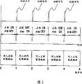
图2为一示意图,显示利用快门眼镜(shutter glasses)产生三维效果的另一公知立体影像显示装置200。于该设计中,当背光206发出的光线通过液晶显示面板202后,左、右眼在不同的时间点可分别看到左眼影像资料及右眼影像资料而产生视觉分离效果。交替显示的左、右眼影像资料必须经由快门眼镜204与一控制电路(未图标)同步操作,如图3所示,利用一切换信号控制快门眼镜204左眼及右眼的开启(On)与关闭(Off),当该切换时序与液晶显示面板202的接收影像(左眼影像资料或右眼影像资料)同步后,显示左眼影像数据时快门眼镜204会遮蔽右眼的视线;反之显示右眼影像数据时快门眼镜204会遮蔽左眼的视线,如此左、右眼影像快速交替显示再借由视觉暂留效应可产生立体视觉效果。FIG. 2 is a schematic diagram showing another conventional stereoscopic
图4为一示意图,显示公知另一立体影像显示装置300的设计。如图4所示,立体影像显示装置300包含一普菲立克立体眼镜304,该立体眼镜304其中一片镜片(例示为左眼镜片)另包含一中性滤光片(neutral filter),使左右两个镜片的透光率不同,借以产生普菲立克效应。普菲立克效应是一种利用大脑对于阴暗刺激的认知比明亮刺激稍微迟缓而形成的光学幻觉,因此,当背光306发出的光线通过液晶显示面板302后,因为图4所示的左眼镜片较暗,虽然透过镜片两眼都会看到相同的影像,但左眼传输影像给大脑的速度会比较慢,如此可构筑出实际上并不存在的空间深度而产生三维效果。如图5所示,利用一切换信号控制普菲立克立体眼镜304左眼及右眼的开启(On)与关闭(Off),当该切换时序与液晶显示面板302的接收影像(左眼或右眼)同步后,显示左眼较暗影像资料时右眼视线被遮蔽,反之显示右眼一般亮度影像资料时左眼的视线被遮蔽,如此左、右眼所感知的明暗影像快速交替变化,仅需写入针对左右眼均相同的二维影像资料而不需另外准备独立的左右眼视差影像画面,即可产生立体视觉效果。FIG. 4 is a schematic diagram showing the design of another conventional stereoscopic
综合上述可知,于图1及图2所示的公知设计中,若欲产生立体视觉效果,必须预先准备左右眼各自独立的视差影像画面;而于图4所示的公知设计中,虽可利用原始的二维影像资料作为输入画面,但仍需同步化立体眼镜左右眼的On/Off切换时序与影像信号传送时序。Based on the above, it can be seen that in the known designs shown in Figures 1 and 2, if a stereoscopic effect is to be produced, separate parallax image frames for the left and right eyes must be prepared in advance; and in the known design shown in Figure 4, although the The original two-dimensional image data is used as the input image, but it is still necessary to synchronize the On/Off switching timing of the left and right eyes of the stereo glasses and the timing of image signal transmission.
发明内容Contents of the invention
因此,本发明的目的在于提供一种立体影像显示装置,其能利用原始的二维影像资料作为输入画面且不须利用快门眼镜(shutter glasses)即可产生立体视觉效果,而可大幅简化显示立体影像的驱动架构并有效降低制造成本。Therefore, the purpose of the present invention is to provide a stereoscopic image display device, which can use the original two-dimensional image data as the input picture and can produce stereoscopic visual effects without using shutter glasses (shutter glasses), and can greatly simplify the display of stereoscopic images. The driving structure of the image can effectively reduce the manufacturing cost.
依本发明的设计,一种立体影像显示装置包含一显示面板、一视差光件、及一亮度控制组件。视差光件设置于显示面板的一侧,以使一观察者透过视差光件观看显示面板时,观察者的左眼及右眼分别看到相异的一第一及一第二视域(viewing zones)。亮度控制组件设置于观察者观看显示面板的视线上,其具有对应第一及第二视域位置分布的一第一及一第二透光区,且第一及第二透光区具有不同的光透过率,使观察者左眼及右眼分别观看第一及第二视域时感知一亮度差。视差光件例如可为液晶光阀(LC shutter)、视差障壁基板(parallax barrier plate)、或柱状透镜(lenticular lens),且亮度控制组件例如可为一液晶光阀或一滤光片基板。According to the design of the present invention, a stereoscopic image display device includes a display panel, a parallax light element, and a brightness control component. The parallax light element is arranged on one side of the display panel, so that when an observer watches the display panel through the parallax light element, the left eye and the right eye of the observer see different first and second visual domains respectively ( viewing zones). The brightness control component is arranged on the line of sight of the observer watching the display panel, and has a first and a second light transmission area corresponding to the position distribution of the first and second viewing areas, and the first and second light transmission areas have different The light transmittance enables the observer to perceive a brightness difference when the left eye and the right eye watch the first and second viewing zones respectively. The parallax optical element can be, for example, a liquid crystal shutter (LC shutter), a parallax barrier plate, or a lenticular lens, and the brightness control component can be, for example, a liquid crystal shutter or a filter substrate.
借由本发明的设计,不仅不需穿戴传统的快门眼镜因而不需进行快门眼镜切换时序与影像信号传送时序的同步化过程;另一方面,亮度控制组件可使左右眼个别视域的亮度产生差异而引致普菲立克效应,如此能利用原始的二维影像资料作为输入画面即可产生立体视觉效果,而不需另外产生左右眼各自独立的视差影像资料。因此,本发明可大幅简化显示立体影像的驱动架构并有效降低制造成本。With the design of the present invention, not only does it not need to wear traditional shutter glasses, so the synchronization process of the switching timing of the shutter glasses and the timing of image signal transmission is unnecessary; on the other hand, the brightness control component can make the brightness of the individual visual fields of the left and right eyes different. This leads to the Pfelek effect, so that the original two-dimensional image data can be used as an input image to generate a stereoscopic visual effect without additionally generating independent parallax image data for the left and right eyes. Therefore, the present invention can greatly simplify the driving structure for displaying stereoscopic images and effectively reduce the manufacturing cost.
附图说明Description of drawings
图1为一示意图,显示公知一自动立体影像显示装置的设计。FIG. 1 is a schematic diagram showing the design of a conventional autostereoscopic image display device.
图2为一示意图,显示利用快门眼镜产生三维效果的另一公知立体影像显示装置。FIG. 2 is a schematic diagram showing another conventional stereoscopic image display device using shutter glasses to produce a 3D effect.
图3为一示意图,显示图2的立体影像显示装置的同步控制过程。FIG. 3 is a schematic diagram showing the synchronous control process of the stereoscopic image display device in FIG. 2 .
图4为一示意图,显示公知另一立体影像显示装置的设计。FIG. 4 is a schematic diagram showing the design of another conventional stereoscopic image display device.
图5为一示意图,显示图4的立体影像显示装置的同步控制过程。FIG. 5 is a schematic diagram showing the synchronous control process of the stereoscopic image display device shown in FIG. 4 .
图6为依本发明一实施例,显示一立体影像显示装置的示意图。FIG. 6 is a schematic diagram showing a stereoscopic image display device according to an embodiment of the present invention.
图7A为一示意简图,显示当本发明的构件叠合后各个具不同透光率区域的相对分布,图7B显示观察者透过液晶光阀观看显示面板时,其左眼及右眼所分别看到的影像。Fig. 7A is a schematic diagram showing the relative distribution of regions with different light transmittances after the components of the present invention are laminated. Fig. 7B shows what the left and right eyes of the observer look at the display panel through the liquid crystal light valve. images seen separately.
图8A为一示意简图,显示当本发明的构件叠合后各个具不同透光率区域的另一相对分布,图8B显示观察者透过液晶光阀观看显示面板时,其左眼及右眼所分别看到的影像。Fig. 8A is a schematic diagram showing another relative distribution of regions with different light transmittances when the components of the present invention are laminated. images seen by the eyes.
图9为显示本发明视差光件的另一实施例的示意图。FIG. 9 is a schematic diagram showing another embodiment of the parallax light element of the present invention.
图10为显示本发明视差光件的另一实施例的示意图。FIG. 10 is a schematic diagram showing another embodiment of the parallax optical element of the present invention.
图11为显示本发明另一实施例的示意图。Fig. 11 is a schematic diagram showing another embodiment of the present invention.
图12为显示本发明另一实施例的示意图。Fig. 12 is a schematic diagram showing another embodiment of the present invention.
符号说明:Symbol Description:
10 立体影像显示装置10 Stereoscopic image display device
12 显示面板12 display panel
14 第一液晶光阀14 The first liquid crystal light valve
16 第二液晶光阀16 second liquid crystal light valve
18 不透光区块18 opaque blocks
20 透光区块20 transparent blocks
22 高透光区22 high light transmittance area
22’投影区域22' projection area
24 低透光区24 low light transmittance area
24’投影区域24' projection area
30 视差障壁基板30 parallax barrier substrate
32 玻璃基板32 glass substrate
34 遮光区块34 shading block
40 柱状透镜40 lenticular lens
42 柱状部42 columnar part
52 视差光件52 parallax light
54 亮度控制组件54 brightness control components
56 透明基板56 transparent substrate
62、72 液晶层62, 72 liquid crystal layer
64、66、74、76 对向电极64, 66, 74, 76 Counter electrode
78 中性滤光片78 neutral filter
100 自动立体影像显示装置100 autostereoscopic image display device
102 液晶显示面板102 LCD display panel
104 液晶光阀104 LCD light valve
106 背光106 backlight
108、112 像素单元108, 112 pixel units
114不透光区块114 opaque blocks
116 观察者116 Observer
200 立体影像显示装置200 Stereoscopic image display device
202 液晶显示面板202 LCD display panel
204 快门眼镜204 shutter glasses
206 背光206 backlight
300 立体影像显示装置300 Stereoscopic image display device
302 液晶显示面板302 LCD display panel
304普菲力克立体眼镜304 Pufeilic Stereoscopic Glasses
306背光306 backlight
R11、G11、B11、R12、G12、B12、R21、G21、B21、R22、G22、B22、R31、G31、B31、R32、G32、B32子像素R11, G11, B11, R12, G12, B12, R21, G21, B21, R22, G22, B22, R31, G31, B31, R32, G32, B32 sub-pixel
M1、M2、N1、N2、O1、O2子像素纵列M1, M2, N1, N2, O1, O2 sub-pixel columns
具体实施方式Detailed ways
图6为依本发明一实施例,显示一立体影像显示装置10的示意图。如图6所示,立体影像显示装置10包含一显示面板12、一第一液晶光阀(LCshutter)14、及一第二液晶光阀16。FIG. 6 is a schematic diagram showing a stereoscopic
如图6所示,显示面板12包含多个红色(R)、绿色(G)或蓝色(B)子像素,各个子像素沿横向(X轴方向)及纵向(Y轴方向)排列形成多道横列及纵列。第一液晶光阀14设置于显示面板12的一侧,用以作为产生左右眼视觉分离效果的视差光件(parallax optic)。当液晶光阀14关闭时,光线可完全透过液晶光阀而为一平面二维(2D)影像显示模式;当液晶光阀14开启时,施加电压会改变液晶分子的配列状态形成多个不透光区块18,借由该不透光区块18产生的视差效果而形成一立体三维(3D)影像显示模式。图6中以投影虚线表示其中一不透光区块P于显示面板12上的投影位置,借以显示不透光区块18与各个子像素的相对位置。由图上可看出各个不透光区块1 8并非以沿Z轴方向完全叠合于一子像素上的方式配置,而是沿横向(X轴方向)偏移一定位移量,亦即不透光区块18的投影位置位于两相邻纵列子像素的交界上,如此交互间隔配置的不透光区块18及透光区块20与各个子像素错置后可产生左、右眼的视觉分离效果。As shown in FIG. 6 , the
第二液晶光阀16是用以调整左右眼个别视域(viewing zones)的显示亮度。当液晶光阀16开启时,可利用施加电压控制其不同区域的光透过率,因此,如图6所示,液晶光阀16上可形成相对的一高透光区22及一低透光区24,而该高、低透光区22、24分布位置对应液晶光阀14上的透光区块20及不透光区块18,举例而言,由高透光区22及低透光区24于第一液晶光阀14上的投影区域22’及24’可看出,高透光区22及低透光区24分别位于不透光区块P的左方及右方。因此,借由第一液晶光阀14产生的视觉分离效果,观察者左眼及右眼具有相异的视域而可分别看到多个第一及第二像素单元,当液晶光阀16上形成相对的高透光区22及低透光区24后,观察者左眼及右眼透过第一液晶光阀14及第二液晶光阀16观看显示面板12时,受到高、低透光区的不同透光率影响,会使左、右眼所分别看到的多个第一及第二像素单元具有不同的亮度。此一左、右眼观看时的亮度差所引致的普菲立克效应,即可提供立体显示视觉效果。The second liquid crystal
图7A为一示意简图,显示当显示面板12、第一液晶光阀14、第二液晶光阀16叠合后各个具不同透光率区域的相对分布。图7B显示观察者透过第一及第二液晶光阀观看显示面板12时,其左眼及右眼所分别看到的影像,其中每三个原色子像素(例如子像素R11、G11、B11)构成一显示点。如图7A所示,因第一液晶光阀14的各个不透光区块18均分布于两相邻子像素间,且每个不透光区块18的左方均为高透光区22而右方均为低透光区24,故观察者左眼看到如图7B左侧所示呈三角配列(delta topology)且亮度较暗的子像素R11、B11、G12、G21、R22、B22、R31、B31、G32,而右眼看到如图7B右侧所示呈三角配列且为一般亮度的子像素G11、R12、B12、R21、B21、G22、G31、R32、B32。因此,当显示面板1 2接收持续变化的动态影像时,左、右眼观看时的亮度差所引致的普菲立克效应可提供立体显示视觉效果。FIG. 7A is a schematic diagram showing the relative distribution of regions with different light transmittances when the
因此,借由本发明的设计,一方面不需穿戴传统的快门眼镜(shutterglasses)因而不需进行快门眼镜切换时序与影像信号传送时序的同步化过程;另一方面,作为亮度控制组件的第二液晶光阀16,可使左右眼个别视域的亮度产生差异而引致普菲立克效应,如此能利用原始的二维影像资料作为输入画面即可产生立体视觉效果,而不需另外产生左右眼各自独立的视差影像资料。因此,本发明可大幅简化显示立体影像的驱动架构并有效降低制造成本。Therefore, by means of the design of the present invention, on the one hand, there is no need to wear traditional shutter glasses (shutterglasses) so that the synchronization process of shutter glasses switching timing and image signal transmission timing is not required; on the other hand, the second liquid crystal as a brightness control component The
于上述实施例中,是以第一液晶光阀14的各个不透光区块1 8及透光区块20对应各个子像素错置形成一西洋棋盘式(checkerboard)分布,且观察者的左、右眼分别看到三角配列的子像素布局为例,说明本发明如何同时利用一视差光件(液晶光阀14)及一亮度控制组件(液晶光阀16)来达到立体显示效果,因于三角配列布局中,红色(R)子像素及绿色(G)子像素可同时交错出现在每一个水平及垂直配列上而可搭配子像素成色技术(sub-pixel rendering)来进一步提高分辨率及影像品质的目的。然而,搭配本发明设计的像素布局完全不限定,举例而言,亦可如图8A所示运用于条纹配列(stripe topology)的子像素布局,亦即不透光区块18对应整道子像素纵列形成为多道暗条纹,且每道暗条纹的左方为一道高透光区22而右方为一道低透光区24,如此观察者左眼看到图8B左侧所示亮度较暗的子像素纵列M1、N1、O1,右眼则看到图8B右侧所示一般亮度的子像素纵列M2、N2、O2,同样可产生立体显示视觉效果。In the above-mentioned embodiment, each
再者,本发明的视差光件并不限定为上述的第一液晶光阀14,而可为任意可产生左、右眼视觉分离效果的组件。举例而言,如图9所示,该视差光件可采用一视差障壁基板(parallax barr ier plate)30。视差障壁基板30于一玻璃基板32上,利用如油墨等不透光材料涂布形成错排的遮光区块34来产生视觉分离效果。或者,亦可如图10所示,该视差光件可采用一柱状透镜(lenticular lens)40,柱状透镜40上形成有多个柱状部42,位于同一纵列的子像素可借由错排的柱状部分别折射进入观察者的右眼及左眼,以产生视觉分离效果。Moreover, the parallax light element of the present invention is not limited to the above-mentioned first liquid crystal
图11为显示本发明另一实施例的示意图。如图11所示,可将视差光件52及亮度控制组件54形成于同一透明基板56上,视差光件52包含夹掣一液晶层62的一组对向电极64及66,亮度控制组件54亦包含夹掣一液晶层72的一组对向电极74及76,借由调整对向电极的分布区域及施加电压的大小,可变化各个区域的光穿透率,以构成视差光件52的不透光区块及亮度控制组件5 4中的高透光区及低透光区。另外,虽然图11例示为视差光件52及亮度控制组件54形成于透明基板56的两对侧上,但其并不限定,亦可将视差光件52及亮度控制组件54形成于透明基板56的同侧。Fig. 11 is a schematic diagram showing another embodiment of the present invention. As shown in Figure 11, the parallax optical element 52 and the brightness control component 54 can be formed on the same transparent substrate 56. The parallax optical component 52 includes a group of opposite electrodes 64 and 66 that clamp a liquid crystal layer 62, and the brightness control component 54 It also includes a set of opposing electrodes 74 and 76 that clamp a liquid crystal layer 72. By adjusting the distribution area of the opposing electrodes and the magnitude of the applied voltage, the light transmittance of each area can be changed to form the parallax optical element 52. The high light transmittance area and the low light transmittance area in the opaque block and the brightness control component 54. In addition, although FIG. 11 illustrates that the parallax light element 52 and the brightness control element 54 are formed on two opposite sides of the transparent substrate 56, it is not limited, and the parallax light element 52 and the brightness control element 54 can also be formed on the transparent substrate 56. on the same side.
再者,本发明的亮度控制组件仅需达到使左、右眼的视域具有亮度差的效果即可,其形成方式并不限定。例如亦可如图12所示,于透明基板56上对应低透光区位置处设置中性滤光片78(neutral filter)来降低光透过率,或直接提供一不具色彩的滤光片基板作为该亮度控制组件,同样可获得产生亮度差的效果。Furthermore, the brightness control component of the present invention only needs to achieve the effect of making the left and right eyes have a brightness difference, and its forming method is not limited. For example, as shown in FIG. 12 , a neutral filter 78 (neutral filter) can be set on the transparent substrate 56 corresponding to the position of the low light transmittance area to reduce the light transmittance, or a colorless filter substrate can be directly provided. As the brightness control component, the effect of generating a brightness difference can also be obtained.
以上所述仅为举例性,而非为限制本发明。任何未脱离本发明的精神与范畴,而对其进行的等效修改或变更,均应包含于申请专利范围中,而非限定于上述的实施例。The above description is only for illustration and not for limiting the present invention. Any equivalent modification or change made without departing from the spirit and scope of the present invention shall be included in the scope of the patent application, rather than limited to the above-mentioned embodiments.
Claims (13)
Translated fromChinesePriority Applications (1)
| Application Number | Priority Date | Filing Date | Title |
|---|---|---|---|
| CN 200610093115CN101094424A (en) | 2006-06-21 | 2006-06-21 | Stereoscopic image display device |
Applications Claiming Priority (1)
| Application Number | Priority Date | Filing Date | Title |
|---|---|---|---|
| CN 200610093115CN101094424A (en) | 2006-06-21 | 2006-06-21 | Stereoscopic image display device |
Publications (1)
| Publication Number | Publication Date |
|---|---|
| CN101094424Atrue CN101094424A (en) | 2007-12-26 |
Family
ID=38992388
Family Applications (1)
| Application Number | Title | Priority Date | Filing Date |
|---|---|---|---|
| CN 200610093115PendingCN101094424A (en) | 2006-06-21 | 2006-06-21 | Stereoscopic image display device |
Country Status (1)
| Country | Link |
|---|---|
| CN (1) | CN101094424A (en) |
Cited By (11)
| Publication number | Priority date | Publication date | Assignee | Title |
|---|---|---|---|---|
| CN101888565A (en)* | 2010-06-30 | 2010-11-17 | 华映光电股份有限公司 | Stereo picture display method and stereo display device |
| CN102162930A (en)* | 2010-02-18 | 2011-08-24 | 住友化学株式会社 | Stereoscopic display system |
| CN102301728A (en)* | 2009-12-04 | 2011-12-28 | 索尼公司 | Video display device, shutter glasses, video display system, and communication method |
| CN102467619A (en)* | 2010-11-08 | 2012-05-23 | 鸿富锦精密工业(深圳)有限公司 | Confidential document reading device and method |
| CN102511167A (en)* | 2009-10-19 | 2012-06-20 | 夏普株式会社 | Image display device and stereoscopic image display system |
| CN102822886A (en)* | 2010-04-05 | 2012-12-12 | 夏普株式会社 | Stereoscopic image display device, display system, driving method, driving device, display control method, display control device, program, and computer-readable recording medium |
| CN103477642A (en)* | 2011-04-11 | 2013-12-25 | 李钟五 | Stereo display panel, apparatus for stereo displaying, and method for displaying image |
| CN103676166A (en)* | 2012-08-31 | 2014-03-26 | 群创光电股份有限公司 | 3D image display device |
| CN105607271A (en)* | 2016-01-04 | 2016-05-25 | 京东方科技集团股份有限公司 | Display module group, display device and driving method thereof |
| JP2018203740A (en)* | 2016-11-01 | 2018-12-27 | 住友化学株式会社 | Compound, liquid crystal composition, optical film, polarizing plate, and optical display |
| CN113895130A (en)* | 2021-07-30 | 2022-01-07 | 上海晟禾智能科技有限公司 | Cover plate with chess playing backlight indication and manufacturing method thereof |
- 2006
- 2006-06-21CNCN 200610093115patent/CN101094424A/enactivePending
Cited By (17)
| Publication number | Priority date | Publication date | Assignee | Title |
|---|---|---|---|---|
| CN102511167A (en)* | 2009-10-19 | 2012-06-20 | 夏普株式会社 | Image display device and stereoscopic image display system |
| CN102301728A (en)* | 2009-12-04 | 2011-12-28 | 索尼公司 | Video display device, shutter glasses, video display system, and communication method |
| CN102162930A (en)* | 2010-02-18 | 2011-08-24 | 住友化学株式会社 | Stereoscopic display system |
| CN102822886B (en)* | 2010-04-05 | 2015-11-25 | 夏普株式会社 | Stereoscopic image display device, display system, driving method, driving device, display control method, and display control device |
| CN102822886A (en)* | 2010-04-05 | 2012-12-12 | 夏普株式会社 | Stereoscopic image display device, display system, driving method, driving device, display control method, display control device, program, and computer-readable recording medium |
| US9128298B2 (en) | 2010-04-05 | 2015-09-08 | Sharp Kabushiki Kaisha | Three-dimensional image display apparatus, display system, driving method, driving apparatus, display controlling method, display controlling apparatus, program, and computer-readable recording medium |
| CN101888565B (en)* | 2010-06-30 | 2012-07-04 | 华映光电股份有限公司 | Stereo picture display method and stereo display device |
| CN101888565A (en)* | 2010-06-30 | 2010-11-17 | 华映光电股份有限公司 | Stereo picture display method and stereo display device |
| CN102467619A (en)* | 2010-11-08 | 2012-05-23 | 鸿富锦精密工业(深圳)有限公司 | Confidential document reading device and method |
| CN103477642A (en)* | 2011-04-11 | 2013-12-25 | 李钟五 | Stereo display panel, apparatus for stereo displaying, and method for displaying image |
| CN103676166A (en)* | 2012-08-31 | 2014-03-26 | 群创光电股份有限公司 | 3D image display device |
| CN103676166B (en)* | 2012-08-31 | 2016-02-24 | 群创光电股份有限公司 | 3D image display device |
| CN105607271A (en)* | 2016-01-04 | 2016-05-25 | 京东方科技集团股份有限公司 | Display module group, display device and driving method thereof |
| US10015476B2 (en) | 2016-01-04 | 2018-07-03 | Boe Technology Group Co., Ltd. | Display module, display device and driving method |
| JP2018203740A (en)* | 2016-11-01 | 2018-12-27 | 住友化学株式会社 | Compound, liquid crystal composition, optical film, polarizing plate, and optical display |
| JP7078467B2 (en) | 2016-11-01 | 2022-05-31 | 住友化学株式会社 | Compounds, liquid crystal compositions, optical films, polarizing plates and optical displays |
| CN113895130A (en)* | 2021-07-30 | 2022-01-07 | 上海晟禾智能科技有限公司 | Cover plate with chess playing backlight indication and manufacturing method thereof |
Similar Documents
| Publication | Publication Date | Title |
|---|---|---|
| TWI312634B (en) | Stereoscopic image display | |
| CN101094424A (en) | Stereoscopic image display device | |
| JP5610977B2 (en) | Display control device | |
| KR100627763B1 (en) | Multiple view display | |
| US8994759B2 (en) | Display | |
| CN101782687B (en) | Display device for displaying three-dimensional images | |
| US8941787B2 (en) | Three-dimensional image display device and driving method thereof | |
| JP5806150B2 (en) | Display device | |
| CN106461960B (en) | Image Data Redundancy Multi-View Orientation Display for High Quality 3D | |
| US20120113510A1 (en) | Display device and display method | |
| CN103067723A (en) | Display device | |
| TW201416710A (en) | Three dimensions display device and displaying method thereof | |
| US10021375B2 (en) | Display device and method of driving the same | |
| KR100828696B1 (en) | Variable Parallax Barrier and Stereoscopic Display | |
| KR20130141867A (en) | 3 dimensional image display device and driving method thereof | |
| TWI471607B (en) | Hybrid multiplexed 3d display and displaying method of hybrid multiplexed 3d image | |
| CN101546043B (en) | Plane stereo hybrid compatible parallax micro-mirror panel and rear-projection free stereo video display | |
| JP5621500B2 (en) | Stereoscopic display device and stereoscopic display method | |
| KR102233116B1 (en) | Stereopsis image display device and method of driving the same | |
| KR101958288B1 (en) | 3D image display device | |
| KR101360780B1 (en) | Glassesless 3 dimensional display apparatus | |
| KR20160021650A (en) | Lenticular lens type stereoscopic 3d display device | |
| EP3186962A1 (en) | Improved resolution for autostereoscopic video displays | |
| TWI429946B (en) | Stereoscopic display device and stereoscopic image displaying method thereof | |
| KR101650380B1 (en) | apparatus for displaying 3D image |
Legal Events
| Date | Code | Title | Description |
|---|---|---|---|
| C06 | Publication | ||
| PB01 | Publication | ||
| C10 | Entry into substantive examination | ||
| SE01 | Entry into force of request for substantive examination | ||
| C02 | Deemed withdrawal of patent application after publication (patent law 2001) | ||
| WD01 | Invention patent application deemed withdrawn after publication |