CN101090667B - Lancet device - Google Patents
Lancet deviceDownload PDFInfo
- Publication number
- CN101090667B CN101090667BCN2005800449289ACN200580044928ACN101090667BCN 101090667 BCN101090667 BCN 101090667BCN 2005800449289 ACN2005800449289 ACN 2005800449289ACN 200580044928 ACN200580044928 ACN 200580044928ACN 101090667 BCN101090667 BCN 101090667B
- Authority
- CN
- China
- Prior art keywords
- lancet device
- housing
- finger grip
- lancet
- shell
- Prior art date
- Legal status (The legal status is an assumption and is not a legal conclusion. Google has not performed a legal analysis and makes no representation as to the accuracy of the status listed.)
- Active
Links
Images


Classifications
- A—HUMAN NECESSITIES
- A61—MEDICAL OR VETERINARY SCIENCE; HYGIENE
- A61B—DIAGNOSIS; SURGERY; IDENTIFICATION
- A61B5/00—Measuring for diagnostic purposes; Identification of persons
- A61B5/15—Devices for taking samples of blood
- A61B5/151—Devices specially adapted for taking samples of capillary blood, e.g. by lancets, needles or blades
- A61B5/15142—Devices intended for single use, i.e. disposable
- A—HUMAN NECESSITIES
- A61—MEDICAL OR VETERINARY SCIENCE; HYGIENE
- A61B—DIAGNOSIS; SURGERY; IDENTIFICATION
- A61B5/00—Measuring for diagnostic purposes; Identification of persons
- A61B5/14—Devices for taking samples of blood ; Measuring characteristics of blood in vivo, e.g. gas concentration within the blood, pH-value of blood
- A61B5/1405—Devices for taking blood samples
- A61B5/1411—Devices for taking blood samples by percutaneous method, e.g. by lancet
- A—HUMAN NECESSITIES
- A61—MEDICAL OR VETERINARY SCIENCE; HYGIENE
- A61B—DIAGNOSIS; SURGERY; IDENTIFICATION
- A61B5/00—Measuring for diagnostic purposes; Identification of persons
- A61B5/15—Devices for taking samples of blood
- A61B5/150007—Details
- A61B5/150015—Source of blood
- A61B5/150022—Source of blood for capillary blood or interstitial fluid
- A—HUMAN NECESSITIES
- A61—MEDICAL OR VETERINARY SCIENCE; HYGIENE
- A61B—DIAGNOSIS; SURGERY; IDENTIFICATION
- A61B5/00—Measuring for diagnostic purposes; Identification of persons
- A61B5/15—Devices for taking samples of blood
- A61B5/150007—Details
- A61B5/150206—Construction or design features not otherwise provided for; manufacturing or production; packages; sterilisation of piercing element, piercing device or sampling device
- A61B5/150259—Improved gripping, e.g. with high friction pattern or projections on the housing surface or an ergonometric shape
- A—HUMAN NECESSITIES
- A61—MEDICAL OR VETERINARY SCIENCE; HYGIENE
- A61B—DIAGNOSIS; SURGERY; IDENTIFICATION
- A61B5/00—Measuring for diagnostic purposes; Identification of persons
- A61B5/15—Devices for taking samples of blood
- A61B5/150007—Details
- A61B5/150374—Details of piercing elements or protective means for preventing accidental injuries by such piercing elements
- A61B5/150381—Design of piercing elements
- A61B5/150412—Pointed piercing elements, e.g. needles, lancets for piercing the skin
- A—HUMAN NECESSITIES
- A61—MEDICAL OR VETERINARY SCIENCE; HYGIENE
- A61B—DIAGNOSIS; SURGERY; IDENTIFICATION
- A61B5/00—Measuring for diagnostic purposes; Identification of persons
- A61B5/15—Devices for taking samples of blood
- A61B5/150007—Details
- A61B5/150374—Details of piercing elements or protective means for preventing accidental injuries by such piercing elements
- A61B5/150381—Design of piercing elements
- A61B5/150503—Single-ended needles
- A—HUMAN NECESSITIES
- A61—MEDICAL OR VETERINARY SCIENCE; HYGIENE
- A61B—DIAGNOSIS; SURGERY; IDENTIFICATION
- A61B5/00—Measuring for diagnostic purposes; Identification of persons
- A61B5/15—Devices for taking samples of blood
- A61B5/150007—Details
- A61B5/150374—Details of piercing elements or protective means for preventing accidental injuries by such piercing elements
- A61B5/150534—Design of protective means for piercing elements for preventing accidental needle sticks, e.g. shields, caps, protectors, axially extensible sleeves, pivotable protective sleeves
- A61B5/150541—Breakable protectors, e.g. caps, shields or sleeves, i.e. protectors separated destructively, e.g. by breaking a connecting area
- A61B5/150549—Protectors removed by rotational movement, e.g. torsion or screwing
- A—HUMAN NECESSITIES
- A61—MEDICAL OR VETERINARY SCIENCE; HYGIENE
- A61B—DIAGNOSIS; SURGERY; IDENTIFICATION
- A61B5/00—Measuring for diagnostic purposes; Identification of persons
- A61B5/15—Devices for taking samples of blood
- A61B5/150007—Details
- A61B5/150374—Details of piercing elements or protective means for preventing accidental injuries by such piercing elements
- A61B5/150534—Design of protective means for piercing elements for preventing accidental needle sticks, e.g. shields, caps, protectors, axially extensible sleeves, pivotable protective sleeves
- A61B5/15058—Joining techniques used for protective means
- A61B5/150618—Integrally moulded protectors, e.g. protectors simultaneously moulded together with a further component, e.g. a hub, of the piercing element
- A—HUMAN NECESSITIES
- A61—MEDICAL OR VETERINARY SCIENCE; HYGIENE
- A61B—DIAGNOSIS; SURGERY; IDENTIFICATION
- A61B5/00—Measuring for diagnostic purposes; Identification of persons
- A61B5/15—Devices for taking samples of blood
- A61B5/150007—Details
- A61B5/150374—Details of piercing elements or protective means for preventing accidental injuries by such piercing elements
- A61B5/150534—Design of protective means for piercing elements for preventing accidental needle sticks, e.g. shields, caps, protectors, axially extensible sleeves, pivotable protective sleeves
- A61B5/150694—Procedure for removing protection means at the time of piercing
- A61B5/150717—Procedure for removing protection means at the time of piercing manually removed
- A—HUMAN NECESSITIES
- A61—MEDICAL OR VETERINARY SCIENCE; HYGIENE
- A61B—DIAGNOSIS; SURGERY; IDENTIFICATION
- A61B5/00—Measuring for diagnostic purposes; Identification of persons
- A61B5/15—Devices for taking samples of blood
- A61B5/150007—Details
- A61B5/150801—Means for facilitating use, e.g. by people with impaired vision; means for indicating when used correctly or incorrectly; means for alarming
- A61B5/150824—Means for facilitating use, e.g. by people with impaired vision; means for indicating when used correctly or incorrectly; means for alarming by visual feedback
- A—HUMAN NECESSITIES
- A61—MEDICAL OR VETERINARY SCIENCE; HYGIENE
- A61B—DIAGNOSIS; SURGERY; IDENTIFICATION
- A61B5/00—Measuring for diagnostic purposes; Identification of persons
- A61B5/15—Devices for taking samples of blood
- A61B5/151—Devices specially adapted for taking samples of capillary blood, e.g. by lancets, needles or blades
- A61B5/15101—Details
- A61B5/15103—Piercing procedure
- A61B5/15107—Piercing being assisted by a triggering mechanism
- A61B5/15111—Semi-automatically triggered, e.g. at the end of the cocking procedure, for instance by biasing the main drive spring or when reaching sufficient contact pressure, the piercing device is automatically triggered without any deliberate action by the user
- A—HUMAN NECESSITIES
- A61—MEDICAL OR VETERINARY SCIENCE; HYGIENE
- A61B—DIAGNOSIS; SURGERY; IDENTIFICATION
- A61B5/00—Measuring for diagnostic purposes; Identification of persons
- A61B5/15—Devices for taking samples of blood
- A61B5/151—Devices specially adapted for taking samples of capillary blood, e.g. by lancets, needles or blades
- A61B5/15101—Details
- A61B5/15115—Driving means for propelling the piercing element to pierce the skin, e.g. comprising mechanisms based on shape memory alloys, magnetism, solenoids, piezoelectric effect, biased elements, resilient elements, vacuum or compressed fluids
- A61B5/15117—Driving means for propelling the piercing element to pierce the skin, e.g. comprising mechanisms based on shape memory alloys, magnetism, solenoids, piezoelectric effect, biased elements, resilient elements, vacuum or compressed fluids comprising biased elements, resilient elements or a spring, e.g. a helical spring, leaf spring, or elastic strap
- A—HUMAN NECESSITIES
- A61—MEDICAL OR VETERINARY SCIENCE; HYGIENE
- A61B—DIAGNOSIS; SURGERY; IDENTIFICATION
- A61B5/00—Measuring for diagnostic purposes; Identification of persons
- A61B5/15—Devices for taking samples of blood
- A61B5/151—Devices specially adapted for taking samples of capillary blood, e.g. by lancets, needles or blades
- A61B5/15101—Details
- A61B5/15126—Means for controlling the lancing movement, e.g. 2D- or 3D-shaped elements, tooth-shaped elements or sliding guides
- A61B5/1513—Means for controlling the lancing movement, e.g. 2D- or 3D-shaped elements, tooth-shaped elements or sliding guides comprising linear sliding guides
- A—HUMAN NECESSITIES
- A61—MEDICAL OR VETERINARY SCIENCE; HYGIENE
- A61B—DIAGNOSIS; SURGERY; IDENTIFICATION
- A61B5/00—Measuring for diagnostic purposes; Identification of persons
- A61B5/15—Devices for taking samples of blood
- A61B5/151—Devices specially adapted for taking samples of capillary blood, e.g. by lancets, needles or blades
- A61B5/15142—Devices intended for single use, i.e. disposable
- A61B5/15144—Devices intended for single use, i.e. disposable comprising driving means, e.g. a spring, for retracting the piercing unit into the housing
- A—HUMAN NECESSITIES
- A61—MEDICAL OR VETERINARY SCIENCE; HYGIENE
- A61B—DIAGNOSIS; SURGERY; IDENTIFICATION
- A61B17/00—Surgical instruments, devices or methods
- A61B2017/0042—Surgical instruments, devices or methods with special provisions for gripping
- A61B2017/00424—Surgical instruments, devices or methods with special provisions for gripping ergonomic, e.g. fitting in fist
Landscapes
- Health & Medical Sciences (AREA)
- Life Sciences & Earth Sciences (AREA)
- Engineering & Computer Science (AREA)
- Heart & Thoracic Surgery (AREA)
- Molecular Biology (AREA)
- Pathology (AREA)
- Physics & Mathematics (AREA)
- Biomedical Technology (AREA)
- Hematology (AREA)
- Medical Informatics (AREA)
- Biophysics (AREA)
- Surgery (AREA)
- Animal Behavior & Ethology (AREA)
- General Health & Medical Sciences (AREA)
- Public Health (AREA)
- Veterinary Medicine (AREA)
- Dermatology (AREA)
- Manufacturing & Machinery (AREA)
- Measurement Of The Respiration, Hearing Ability, Form, And Blood Characteristics Of Living Organisms (AREA)
Abstract
Description
Translated fromChinese技术领域technical field
本发明通常涉及医疗穿刺装置,一般称之为刺血针,用于从患者体内取得血样,更具体地说,本发明涉及以人机工程学方式设计的易于由使用者使用和操纵的刺血针装置。The present invention relates generally to medical lancing devices, commonly referred to as lancets, for taking blood samples from a patient, and more particularly to ergonomically designed lancets that are easy to use and manipulate by a user needle device.
背景技术Background technique
刺血针装置用在医疗领域,用于刺入患者皮肤以从患者体内获取毛细血管血样。某些疾病(诸如糖尿病)要求定时测试患者的血液以监控例如患者的血糖水平。另外,试验箱(诸如胆固醇试验箱)通常需要血样来进行分析。血液收集程序通常包括刺破手指或其它合适的身体部位以获取血样。通常,所述测试所需的血液量较少,并且较小的刺伤或切口通常就能提供足够用于这些测试的血液量。Lancet devices are used in the medical field for piercing the skin of a patient to obtain a capillary blood sample from the patient. Certain diseases, such as diabetes, require periodic testing of a patient's blood to monitor, for example, the patient's blood glucose level. Additionally, test kits, such as cholesterol test kits, often require a blood sample for analysis. Blood collection procedures typically involve pricking a finger or other suitable body part to obtain a blood sample. Typically, the tests require a smaller amount of blood, and a small puncture or incision usually provides enough blood for these tests.
各种刺血针装置可大批供应给医院、门诊所、医务室等,以及单独用户。所述装置通常包括尖端件(诸如针),或刃形件(诸如刀片),其用于在患者皮肤上形成快速的刺伤或切口以提供少量血液流出。对于许多人来说,用手持式的针或刀片刺破自己的手指从生理上和心理上通常都是困难的。因此,刺血针装置已逐步发展成为自动装置,所述自动装置在触发机构的驱动下刺入或割破患者皮肤。在一些装置中,在使用者将其触发之前,针或刀片都保持在待用位置,其中使用者可为负责从患者体内取血的医务人员,或者是患者本人。在触发的情况下,针或刀片刺入或切割患者的皮肤(例如手指上)。通常,装置中包含弹簧以提供刺入或切割患者的皮肤所需的足够的力。Various lancet devices can be supplied in bulk to hospitals, outpatient clinics, infirmaries, etc., as well as individual users. The devices typically include a pointed piece, such as a needle, or a bladed piece, such as a blade, which is used to make a quick puncture or incision in the patient's skin to provide a small outflow of blood. Pricking one's own finger with a hand-held needle or blade is often physically and psychologically difficult for many people. Accordingly, lancet devices have gradually evolved into automatic devices that are driven by a trigger mechanism to pierce or cut the patient's skin. In some devices, the needle or blade remains in the ready position until it is triggered by a user, either the medical staff responsible for drawing blood from the patient, or the patient himself. In the event of a trigger, the needle or blade penetrates or cuts the patient's skin (eg, on a finger). Typically, a spring is included in the device to provide sufficient force to penetrate or cut the patient's skin.
医疗领域中最重要的是,在使用之前所述医疗穿刺装置或刺血针处于无菌状态下。目前,通常(毫无例外地),在被分配给医务人员和需要所述装置的公众成员之前,医疗穿刺装置或刺血针是在无菌状态下制造和包装的。无菌包装保持了装置的无菌,确保在使用之前周围环境不会污染到装置。另外,还有这样的重要性,即,在装置的使用之后,使用者或另一人不会接触到针或刀片。出于对血液携带疾病的担忧,要求医务人员要特别小心与患者血液相接触的医疗装置。因此,刺血针设计的重要方面涉及,在从患者体内抽取血样之后防止装置的针或刀片弄伤使用者或其他人。一旦使用后,就应罩住针或刀片以免针或刀片弄伤使用者或操纵装置的其他人。而且,刺血针装置应为一次性的,从而消除由于针或刀片用在不止一个人身上而导致的疾病传染。在这点上,理想地,刺血针装置被设计成用于一次启用的,并且具有用于防止重复使用的安全措施。It is of utmost importance in the medical field that the medical piercing device or lancet is sterile before use. Currently, medical piercing devices or lancets are generally (without exception) manufactured and packaged under sterile conditions prior to being distributed to medical personnel and members of the public who require the device. Sterile packaging maintains the sterility of the device, ensuring that the surrounding environment does not contaminate the device prior to use. In addition, it is also important that the user or another person does not come into contact with the needle or blade after use of the device. Concerns about blood-borne diseases have required medical staff to take extra care with medical devices that come into contact with a patient's blood. Accordingly, an important aspect of lancet design concerns preventing injury to the user or others by the needle or blade of the device after a blood sample has been drawn from the patient. Once in use, the needle or blade should be covered to prevent the needle or blade from injuring the user or others operating the device. Also, the lancet device should be disposable, thereby eliminating the spread of disease due to the use of the needle or blade on more than one person. In this regard, ideally the lancet device is designed for one-time activation and has safety measures to prevent re-use.
近年来在增加操作和处理用过的刺血针装置的安全性方面已取得进展。例如,通常可买到这样的刺血针,它们为单发射装置,其特征在于,刺入和切割元件从装置中自动地弹出以及缩回到装置中。在美国专利No.6,432,120;No.6,248,120;No.5,755,733和No.5,540,709中公开了这种医疗刺入装置的实例。Progress has been made in recent years to increase the safety of handling and disposing of used lancet devices. For example, lancets are commonly available as single-firing devices characterized in that the piercing and cutting elements are automatically ejected from and retracted into the device. Examples of such medical penetration devices are disclosed in US Patent Nos. 6,432,120; 6,248,120; 5,755,733; and 5,540,709.
授权给Teo的美国专利No.6,432,120公开了一种包括固定器的刺血针装置,该固定器容纳弹簧加载刺血针结构。弹簧加载刺血针结构包括单个弹簧,用于在结构触发的情况下进行刺血针的弹出和缩回。授权给Wyszogrodzki的美国专利No.6,248,120公开了一种刺血针装置,其包括外壳、护罩部分、具有刺入尖的活塞、以及在内部翼件在外壳中破裂的情况下分别弹出和缩回活塞的驱动和返回弹簧。授权给Morita的美国专利No.5,755,733公开了一种包括组合的固定器和刺血针结构的刺血针装置。刺血针结构包括具有刺入尖的刺血针部件和可压缩弹簧件,该可压缩弹簧件在一对驱动臂的驱动下使得刺血针部件刺入患者的皮肤。US Patent No. 6,432,120 to Teo discloses a lancet device including a holder that accommodates a spring loaded lancet structure. A spring-loaded lancet mechanism includes a single spring for ejection and retraction of the lancet when the mechanism is triggered. U.S. Patent No. 6,248,120 to Wyszogrodzki discloses a lancet device comprising a housing, a shield portion, a piston with a piercing point, and ejection and retraction, respectively, in the event of an inner wing rupture in the housing. Piston drive and return spring. US Patent No. 5,755,733 to Morita discloses a lancet device comprising a combined holder and lancet structure. The lancet structure includes a lancet member having a piercing point and a compressible spring member which, driven by a pair of driving arms, causes the lancet member to penetrate the patient's skin.
授权给Ramel的美国专利No.5,540,709公开了一种刺血针装置,其包括围住可滑动触发器的外壳,该触发器用于触发压缩弹簧,该压缩弹簧激励刺血针部件刺入患者的皮肤。外壳包括一对接合刺血针部件主体的内部指状物,之后该内部指状物通过使用者向可滑动的触发器施加的轴向力而解除与接合刺血针部件主体的接合。在美国专利No.4,869,249和No.4,817,603中公开了本领域中公知的其他医疗穿刺装置或刺血针。这些参考文献中公开的装置包括用于保护针或保持针无菌的盖。U.S. Patent No. 5,540,709 to Ramel discloses a lancet device that includes a housing that encloses a slidable trigger for activating a compression spring that energizes the lancet member to penetrate the patient's skin . The housing includes a pair of inner fingers that engage the lancet component body, which are then disengaged from engaging the lancet component body by an axial force applied by a user to the slidable trigger. Other medical piercing devices or lancets known in the art are disclosed in US Patent Nos. 4,869,249 and 4,817,603. The devices disclosed in these references include covers for protecting or keeping the needles sterile.
在刺血针设计方面的另一个重要考虑事项是能使得使用者用他或她的指尖操纵装置。理想地,刺血针装置可容易地保持在使用者的指尖之间,以使使用者在刺血针装置皮肤刺入过程中在刺血针装置上可进行控制。市场上可得到的典型刺血针装置设计得并不易于操作者使用。在一些设计中,例如,刺血针装置的外壳简单地为与矩形护罩部分配合的矩形盒。在前述设计中,没有为使用者提供用其指尖抓住装置的表面。另外,护罩部分的形状不适用于指示使用者刺入件在哪里与装置脱开以刺入患者的皮肤。当护罩部分被放置在患者皮肤上时使用者必须对刺入件的适当脱开位置作一个估计。通常,市场上可得到的刺血针装置设计不是使用者方便类型的,在刺血针设计的该领域存在重要的需求。Another important consideration in lancet design is to enable the user to manipulate the device with his or her fingertips. Ideally, the lancet device is easily held between the user's fingertips to allow the user control over the lancet device during skin penetration of the lancet device. Typical lancet devices available on the market are not designed for ease of use by the operator. In some designs, for example, the housing of the lancet device is simply a rectangular box that mates with a rectangular shield portion. In the foregoing designs, no surface is provided for the user to grip the device with his fingertips. Additionally, the shape of the shield portion is not suitable for indicating to the user where the piercing member has disengaged from the device to penetrate the patient's skin. The user must make an estimate of the proper disengagement position of the piercing member when the shield portion is placed on the patient's skin. Typically, commercially available lancet device designs are not of a user-friendly type and there is a significant need in this area of lancet design.
发明内容Contents of the invention
考虑到前述问题,医疗领域通常存在对于这样一种医疗穿刺装置的需求,所述装置易于为使用者操纵和使用,同时确保在使用之前无菌以及使用之后安全地丢弃。另外,在医疗领域存在对于用于收集血样的简单、价廉、可靠、自驱动、以及一次性医疗穿刺装置的需求。In view of the foregoing, there is generally a need in the medical field for a medical puncturing device that is easy to manipulate and use for a user while ensuring sterility before use and safe disposal after use. Additionally, there is a need in the medical field for a simple, inexpensive, reliable, self-driven, and disposable medical puncture device for collecting blood samples.
本发明的一个实施例提供了一种刺血针装置,其通常包括外壳,该外壳包括在前端和后端之间延伸的相对横向侧部,具有沿相对横向侧部中的至少一个(通常为其两者)的一部分延伸的多个纵向肋。多个纵向肋在一个或两个相对横向侧部上形成手指抓持部。护罩关于该外壳为同轴且可移动的。由使用者施加在手指抓持部上的轴向压力使得外壳与护罩相对于彼此从第一位置(在该位置中,护罩从外壳的前端向外延伸)移动到第二位置(在该位置中,护罩至少部分地移动到外壳中)。One embodiment of the present invention provides a lancet device generally comprising a housing including opposing lateral sides extending between a front end and a rear end, with A plurality of longitudinal ribs extending from a portion of both). A plurality of longitudinal ribs form finger grips on one or two opposing lateral sides. The shroud is coaxial and movable with respect to the housing. Axial pressure exerted by the user on the finger grip causes the housing and shroud to move relative to each other from a first position (in which the shroud extends outwardly from the forward end of the housing) to a second position (in which the shroud extends outwardly from the forward end of the housing). position, the shield moves at least partially into the housing).
纵向肋可沿外壳的两个相对横向侧部的一部分延伸,在两个相对横向侧部上形成手指抓持部。而且,每个纵向肋的一部分可具有将手指抓持部形成通常为凹入表面的轮廓,而纵向肋的另一部分可具有将手指抓持部形成通常为凸出表面的轮廓。在一个实施例中,纵向肋具有在邻近外壳前端的相对横向侧部的一部分处通常形成前部凸出表面而在邻近外壳后端的相对横向侧部的一部分处通常形成后部凸出表面的轮廓,而在前部凸出表面与后部凸出表面之间形成有凹入表面。在这样的实施例中,形成前部凸出表面和后部凸出表面的纵向肋可通过凹入表面对齐以在外壳的至少相对横向侧部上将手指抓持部形成为凹口。另外,在所述实施例中,纵向肋可形成通常为椭圆形的凹入表面。The longitudinal rib may extend along a portion of two opposing lateral sides of the housing forming finger grips on the two opposing lateral sides. Also, a portion of each longitudinal rib may have a contour forming the finger grip into a generally concave surface, while another portion of the longitudinal rib may have a contour forming the finger grip into a generally convex surface. In one embodiment, the longitudinal rib has a profile that forms a generally forward convex surface at a portion of the opposite lateral side adjacent the front end of the housing and generally forms a rear convex surface at a portion of the opposing lateral side adjacent the rear end of the housing , and a concave surface is formed between the front convex surface and the rear convex surface. In such an embodiment, the longitudinal ribs forming the front and rear convex surfaces may be aligned by the concave surfaces to form the finger grips as indentations on at least opposite lateral sides of the housing. Additionally, in the described embodiments, the longitudinal ribs may form a generally elliptical concave surface.
外壳还可包括形成在外壳后端上的手指抓持部凹口,用于在刺血针装置的使用过程中容纳使用者的手指。此外,护罩可限定多个沿圆周隔开的凹口,用于在视觉上指示出设在外壳和/或护罩中的刺入件的对齐位置。The housing may also include a finger grip notch formed on the rear end of the housing for receiving a user's finger during use of the lancet device. Additionally, the shroud may define a plurality of circumferentially spaced notches for visually indicating the alignment of piercing members disposed within the housing and/or shroud.
在另一个实施例中,刺血针装置包括在前端与后端之间延伸的外壳,具有通过外壳的前端同轴地延伸且相对于外壳可移动的护罩,以及设在外壳中并在护罩相对于外壳移动的情况下适于穿过护罩前端中的开口的刺血针组件。所述刺血针装置进一步包括可去除调整片部件,该可去除调整片部件具有用于保持刺血针组件的针尖无菌的内部,以及用于封住护罩前端中的开口并适于保持护罩和外壳相对于彼此轴向移动的外部。In another embodiment, a lancet device includes a housing extending between a front end and a rear end, having a shield extending coaxially through the front end of the housing and movable relative to the housing, and A lancet assembly adapted to pass through the opening in the forward end of the shield with movement of the shield relative to the housing. The lancet device further includes a removable tab member having an interior for maintaining sterility of the needle tip of the lancet assembly, and for sealing an opening in the forward end of the shield and adapted to retain The shroud and outer shell move axially relative to each other.
调整片部件的内部可包括基本上封住针尖的杆,调整片部件的外部可进一步包括适于由使用者抓住的抓持部。调整片部件的外部还可包括悬垂裙部,形成得用于与从外壳前端处延伸的护罩前端的外表面接合。The interior of the tab member may include a stem that substantially encloses the needle tip, and the exterior of the tab member may further include a grip adapted to be grasped by a user. The exterior of the tab member may also include a depending skirt formed to engage an outer surface of the shroud front end extending from the front end of the housing.
抓持部可进一步包括桨状件,用于由使用者抓住。桨状件可具有相对的纵向边缘,它们是相对弯曲的,以使桨状件的相对侧限定出用于指示给使用者旋转方向的轮廓,以旋转调整片部件从而便于从针尖上去除调整片部件。穿过桨状件而截的横向截面可限定出通常为椭圆形的形状。然而,桨状件可限定其他对称的横向截面形状,诸如圆形或多边形,或具有不对称的横向截面形状。桨状件的相对侧部可为凹形的,并且其上可包括至少一个凸起的抓持片。The grip may further include a paddle for grasping by a user. The paddle may have opposite longitudinal edges that are relatively curved such that the opposite sides of the paddle define a contour for indicating to the user the direction of rotation to rotate the tab member to facilitate removal of the tab from the needle tip. part. A transverse cross-section through the paddle may define a generally oval shape. However, the paddle may define other symmetrical transverse cross-sectional shapes, such as circular or polygonal, or have an asymmetrical transverse cross-sectional shape. The opposite side of the paddle may be concave and may include at least one raised grip tab thereon.
桨状件可限定相对的纵向弯曲部分。相对的纵向弯曲部分可通常为椭圆形状的。桨状件可限定至少一个成形凹口,限定在其至少一侧中。成形凹口可通常为圆形、椭圆形或多边形形状的。The paddles may define opposing longitudinal bends. The opposing longitudinal curvature may be generally elliptical in shape. The paddle may define at least one shaped recess defined in at least one side thereof. The shaped recesses may be generally circular, oval or polygonal in shape.
调整片部件的抓持部可限定相对的手指抓持凹口,用于由使用者抓持。抓持部手指抓持凹口可为凹入的。调整片部件的抓持部可具有限定了螺旋状结构的中间部分。每个手指抓持凹口均可包括至少一个凸起的抓持调整片。而且,调整片部件的抓持部可从杆上脱离。The grip portion of the tab member may define opposing finger grip notches for gripping by a user. The grip finger grip notch may be concave. The grip portion of the tab member may have a middle portion defining a helical structure. Each finger grip recess may include at least one raised grip tab. Also, the gripping portion of the tab member can be detached from the rod.
至少一个手指抓持凹口可包括凹入表面形状,其基本上面向沿横向远离轴向穿过刺血针组件的轴线。凹入表面形状可为半圆形、椭圆形、双曲线或抛物线形状。The at least one finger grip recess may comprise a concave surface shape that faces substantially transversely away from an axis passing axially through the lancet assembly. The concave surface shape can be semicircular, elliptical, hyperbolic or parabolic in shape.
无菌调整片部件相对于护罩还可移除并与护罩和/或外壳的前端相接合以防止护罩相对于外壳移动,这可导致内部驱动机构使得刺血针组件突出到刺入位置。例如,悬垂中空裙部可至少部分地包围护罩并接合外壳远端以防止护罩相对于外壳移动。裙部可适于完全将护罩封在其中,并且护罩可摩擦保持在裙部中。The sterile tab member is also removable relative to the shield and engages the forward end of the shield and/or housing to prevent movement of the shield relative to the housing, which may cause the internal drive mechanism to protrude the lancet assembly into the piercing position . For example, a depending hollow skirt may at least partially surround the shroud and engage the distal end of the housing to prevent movement of the shroud relative to the housing. The skirt may be adapted to completely enclose the shroud therein, and the shroud may be frictionally retained in the skirt.
当结合附图阅读时,从以下详细描述中将明白本发明的其他细节和优点。Other details and advantages of the invention will become apparent from the following detailed description when read in conjunction with the accompanying drawings.
附图说明Description of drawings
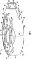
图1是根据本发明实施例的刺血针装置的透视图;Figure 1 is a perspective view of a lancet device according to an embodiment of the present invention;
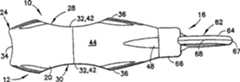
图2是图1刺血针装置的侧视图;Figure 2 is a side view of the lancet device of Figure 1;
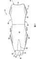
图3是图1刺血针装置的相反侧视图;Figure 3 is an opposite side view of the lancet device of Figure 1;
图4是图1刺血针装置的远端视图;Figure 4 is a distal view of the lancet device of Figure 1;
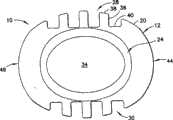
图5是图1刺血针装置的近端视图;Figure 5 is a proximal view of the lancet device of Figure 1;
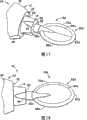
图6是图1刺血针装置的远端的透视图;Figure 6 is a perspective view of the distal end of the lancet device of Figure 1;
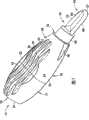
图7是所示刺血针装置的透视图,具有根据第一实施例的可去除无菌调整片部件;Figure 7 is a perspective view of the illustrated lancet device with a removable sterile tab member according to the first embodiment;
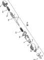
图7A是根据本发明实施例的刺血针装置的分解透视图,示出了内部驱动机构;7A is an exploded perspective view of a lancet device showing an internal drive mechanism in accordance with an embodiment of the present invention;
图8是图7刺血针装置的平面图;Figure 8 is a plan view of the lancet device of Figure 7;
图9是图7刺血针装置的侧视图;Figure 9 is a side view of the lancet device of Figure 7;
图10是图7刺血针装置的远端视图;Figure 10 is a distal view of the lancet device of Figure 7;
图11是图7刺血针装置的近端视图;Figure 11 is a proximal view of the lancet device of Figure 7;
图12是图7刺血针装置的透视和部分横截面图,示出了调整片部件的横截面;12 is a perspective and partial cross-sectional view of the lancet device of FIG. 7 showing a cross-section of the tab member;
图13是图7刺血针装置的远端图和部分横截面图,示出了调整片部件的横截面;13 is a distal view and partial cross-sectional view of the lancet device of FIG. 7 showing a cross-section of the tab member;
图14是图7刺血针装置的分解透视图,示出了与刺血针装置的主体相分离的调整片部件;14 is an exploded perspective view of the lancet device of FIG. 7 showing the tab member separated from the main body of the lancet device;
图14A是替换实施例中所示的刺血针装置的分解透视图,示出了调整片部件和包括相应凸轮状接合表面外壳的前表面,以促进调整片部件与刺血针装置主体的分离;14A is an exploded perspective view of the lancet device shown in an alternative embodiment showing the tab member and the front surface of the housing including corresponding cam-like engagement surfaces to facilitate separation of the tab member from the body of the lancet device ;
图15是图14的刺血针装置与调整片部件的特写和旋转透视图;Figure 15 is a close-up and rotated perspective view of the lancet assembly and tab assembly of Figure 14;
图16是图15的刺血针装置与调整片部件的分解透视图,示出了调整片部件的可分离部件;Fig. 16 is an exploded perspective view of the lancet assembly and tab assembly of Fig. 15, showing separable components of the tab assembly;
图17是具有第二实施例调整片部件的刺血针装置的远端的透视图;17 is a perspective view of the distal end of a lancet device having a second embodiment tab member;
图18是图17刺血针装置的平面图;Figure 18 is a plan view of the lancet device of Figure 17;
图19是图17刺血针装置的侧视图;Figure 19 is a side view of the lancet device of Figure 17;
图20是图17刺血针装置的透视和部分横截面图,示出了调整片部件的第二实施例的横截面;20 is a perspective and partial cross-sectional view of the lancet device of FIG. 17 showing a cross-section of a second embodiment of the tab member;
图21是图17刺血针装置的远端图和部分横截面图,示出了调整片部件的第二实施例的横截面;21 is a distal view and partial cross-sectional view of the lancet device of FIG. 17 showing a cross-section of a second embodiment of the tab member;
图22是图175的刺血针装置与调整片部件的分解透视图,示出了第二实施例的调整片部件的可分离部件;22 is an exploded perspective view of the lancet assembly and tab assembly of FIG. 175 showing the separable components of the tab assembly of a second embodiment;
图23是具有第三实施例调整片部件的刺血针装置的远端的透视图;23 is a perspective view of the distal end of a lancet device having a third embodiment tab member;
图24是图23中所示的调整片部件的平面图;Figure 24 is a plan view of the tab assembly shown in Figure 23;
图25是图24的调整片部件的侧视图;Figure 25 is a side view of the tab assembly of Figure 24;
图26是图24的调整片部件的远端图;Figure 26 is a distal view of the tab assembly of Figure 24;
图27是调整片部件的第四实施例的透视图;Figure 27 is a perspective view of a fourth embodiment of a tab member;
图28是图27的调整片部件的平面图;Figure 28 is a plan view of the tab assembly of Figure 27;
图29是图27的调整片部件的侧视图;Figure 29 is a side view of the tab assembly of Figure 27;
图30是图27的调整片部件的相反侧视图;Figure 30 is an opposite side view of the tab assembly of Figure 27;
图31是图27的调整片部件的远端图;Figure 31 is a distal view of the tab assembly of Figure 27;
图32是调整片部件的第五实施例的透视图;Figure 32 is a perspective view of a fifth embodiment of a tab member;
图33是图32的调整片部件的平面图;Figure 33 is a plan view of the tab assembly of Figure 32;
图34是图32的调整片部件的侧视图;Figure 34 is a side view of the tab assembly of Figure 32;
图35是图32的调整片部件的相反侧视图;Figure 35 is an opposite side view of the tab assembly of Figure 32;
图36是图32的调整片部件的远端图;Figure 36 is a distal view of the tab assembly of Figure 32;
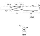
图37是调整片部件的第六实施例的透视图;Figure 37 is a perspective view of a sixth embodiment of a tab member;
图38是图37的调整片部件的平面图;Figure 38 is a plan view of the tab assembly of Figure 37;
图39是图37的调整片部件的侧视图;Figure 39 is a side view of the tab assembly of Figure 37;
图40是图37的调整片部件的远端图;Figure 40 is a distal view of the tab assembly of Figure 37;
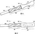
图41是调整片部件的第七实施例的透视图;Figure 41 is a perspective view of a seventh embodiment of a tab member;
图42是图41的调整片部件的平面图;Figure 42 is a plan view of the tab assembly of Figure 41;
图43是图41的调整片部件的侧视图;Figure 43 is a side view of the tab assembly of Figure 41;
图44是图41的调整片部件的远端图;Figure 44 is a distal view of the tab assembly of Figure 41;
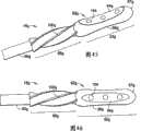
图45是调整片部件的第八实施例的透视图;Figure 45 is a perspective view of an eighth embodiment of a tab member;
图46是图45的调整片部件的平面图;Figure 46 is a plan view of the tab assembly of Figure 45;
图47是图45的调整片部件的侧视图;Figure 47 is a side view of the tab assembly of Figure 45;
图48是图45的调整片部件的远端图;Figure 48 is a distal view of the tab assembly of Figure 45;
图49是根据本发明的刺血针装置的替换实施例的侧视图;Figure 49 is a side view of an alternate embodiment of a lancet device in accordance with the present invention;
图50是根据本发明的刺血针装置的替换实施例的侧视图;Figure 50 is a side view of an alternate embodiment of a lancet device in accordance with the present invention;
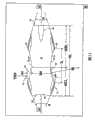
图51是图1刺血针装置的相对侧视图,示出了平面和尺寸;以及Figure 51 is an opposite side view of the lancet device of Figure 1, showing plan and dimensions; and
图52是图1刺血针装置的近端图,示出了平面和尺寸。52 is a proximal view of the lancet device of FIG. 1 showing plan and dimensions.
具体实施方式Detailed ways
为了在下文中进行描述,词语“上部”、“下部”、“右”、“左”、“竖直”、“水平”、“顶部”、“底部”、“横向”、“纵向”以及类似词语,若使用的话,应与本发明有关,与其在附图中的定向一样。然而,应该理解的是,除非明白地指定为相反情况,否则本发明可设想许多替换改变和实施例。还应该理解的是,附图中所示且文中所述的特定装置和实施例都仅是本发明的示例性实施例。For purposes of the description hereinafter, the words "upper," "lower," "right," "left," "vertical," "horizontal," "top," "bottom," "transverse," "longitudinal," and similar words , if used, shall relate to the invention, as it is oriented in the drawings. It should be understood, however, that the invention is conceivable to numerous alternative changes and embodiments unless expressly specified to the contrary. It should also be understood that the particular devices and embodiments shown in the drawings and described herein are merely exemplary embodiments of the invention.
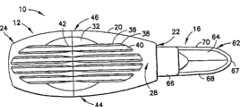
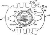
参照图1-7,其中一般示出了根据本发明的刺血针装置10。刺血针装置10通常包括外壳12和可关于外壳12移动的护罩14。如图7-48中所示的以及文中进一步描述的,刺血针装置10还包括无菌调整片部件16,适于与设置在外壳12中的刺入件(未示出)相联或相连接。护罩14与外壳12同轴且可相对于外壳12移动。护罩14还部分地设置在外壳12中并从外壳12中向外延伸。Referring to Figures 1-7, there is generally shown a
外壳12具有细长壳主体20,其具有向前端或远端22和向后端或近端24。在一个实施例中,远端22与近端24之间的壳主体20的轴向长度(在图51中示作外壳长度HL)在1.2与1.9英寸之间,诸如在约1.3与约1.7英寸之间,更典型地,在1.4与1.6英寸之间。如图1中所示的,壳主体20可包括在配合线(图1中邻近元件标号“42”和“32”)附近配合的远端部和分离的近端部。如图51中所示的,外壳底部长度HBL与外壳盖长度HCL表示出该配合线的位置。外壳盖长度HCL可大于总长度HL的20%。例如,HCL可在0.35与0.90英寸之间,诸如在0.50与0.74英寸之间,更典型地,在0.60与0.68英寸之间。可替换地,外壳盖长度HCL可表示为外壳12的长度(如图51中由HL表示的)的函数。例如,外壳盖长度可具有约0.23×HL与0.59×HL之间的长度HCL,诸如在0.33×HL与0.48×HL之间,尤其是在0.39×HL与0.44×HL之间。The
向前端或远端22限定了向前或远端开口26,护罩14穿过该开口26并与壳主体20同轴。通常为细长的壳主体20具有相对的横向侧28、30,它们基本上关于平面A对称地设置,如图51-52所示的。壳主体20的每个横向侧28、30均限定了手指抓持部(诸如凹口)32。而两个相对的手指抓持部凹口32被设在壳主体20上,应该理解的是,根据本发明可仅提供一个形成在壳主体20中的手指抓持凹口32。两个相对手指抓持凹口32的使用对于刺血针装置10的容易使用和操纵是优选的,如文中进一步描述的。手指抓持部(诸如凹口)32可形成为壳主体20中的凹陷部分或凹槽,并且也可由多个纵向延伸肋36形成,如下文中更详细地描述的。Toward the forward or
壳主体20的向后端或近端24限定了向后端或近端手指抓持凹口34。近端手指抓持凹口34也可形成为凹陷部分或凹槽,但是是在壳主体20的近端24上。侧部手指抓持凹口32和近端手指抓持凹口34提供了符合人体工程学形状的表面,所述表面基本上与使用者的指尖相符以在放血、采血或集血程序中帮助使用者操纵刺血针装置10并使用刺血针装置10。侧部手指抓持凹口32和近端手指抓持凹口34为使用者提供了多个手指抓持位置。由侧部手指抓持凹口32和近端手指抓持凹口34提供的多个手指抓持位置通过降低环境因素(诸如溢出的血液、湿度或其他因素)影响刺血针装置10的定位和驱动的可能性而改进了刺血针装置的操纵特性。The rearward or
壳主体20还包括沿壳主体20延伸的多个纵向肋36,并且可与壳主体20整体形成。肋36基本上关于图51-52的平面A被设在壳主体20的相对侧28、30上,并沿壳主体20长度的至少一部分纵向延伸(大致从壳主体20的近端24至远端22)。肋36的轮廓通常限定了侧部手指抓持凹口32,其中肋36穿过由壳主体20中的手指抓持凹口32限定的凹陷或凹进区域。如图4中所示的,肋36通常具有矩形横截面。然而,各个肋36的尖部38被形成或削尖以通常与壳主体20的通常为椭圆形横截面形状相配,并且具体地,与形成在向前端或远端22和向后端或近端24附近的壳主体20的椭圆形横截面形状相配。肋36在彼此之间限定了槽40。槽40的总数通常等于肋36的数量加1。因此,如图4中所示的,槽40为4个,而肋36的数量为3个。肋36通常改进壳主体20与使用者指尖之间的抓持。肋36与侧部手指抓持凹口32相组合,也为使用者提供了视觉和触觉提示以指示使用者放置其指尖的位置。而且,每个肋36都提供了用于减小缩孔(可在模压元件冷却后发生,尤其是对于厚壁区域)的装置。如图52中所示的,肋36具有宽度RW,而槽40具有宽度GW。在一个实施例中,肋36和槽40具有约0.02-0.09英寸之间的宽度,例如,约0.03与0.07英寸之间,尤其是0.04与0.06英寸之间。肋36和槽40的宽度不必彼此相同。The
通常,如图51和图52中所示的,壳主体20关于平面A和B对称,平面A和B两者基本上是沿壳主体20的定向穿过壳主体20的竖直和水平的平面,如图51-52中所示的。壳主体20的对称是关于穿过壳主体20的基本为竖直的平面A显示出来的。平面B基本上穿过通过刺血针装置10的质心限定的纵向轴或由基本上具有轴线的刺入尖、调整片部件16、或刺血针装置10的其他零件限定的轴线。平面B也正交于(垂直于)平面A且还穿过轴线。Generally, as shown in FIGS. 51 and 52 , the
正如图4所示的,壳主体20具有通常为椭圆形或扁长的横截面。壳主体20的相对侧28、30形成了椭圆形横截面的长侧而其余两个相对侧44、46形成了椭圆形横截面的两个短侧并可称作端部44、46。而且,壳主体20的纵向横截面也具有通常为椭圆形或扁长的横截面(正如图52和图51所示的平面B的普通横截面所限定的)。这样的普通椭圆形形状至少部分地由纵向肋36的一部分的轮廓限定,该纵向肋36的一部分形成邻近向前端或远端22和向后端或近端24的相对横向侧28、30处的凸出表面,如图51中所示的。而且,手指抓持部以壳主体20外表面中的凹形形状的凹陷或凹槽形成为壳主体20的相对侧28、30上的凹口32,用于容纳刺血针装置10的使用者的指尖。所述手指抓持凹口32是由纵向肋36的一部分形成的,该一部分的轮廓是在邻近向前端或远端22的肋36的向前凸出表面与邻近向后端或近端24的肋36的向后凸出表面之间形成通常为凹入的表面。形成向前凸出表面与向后凸出表面的纵向肋36通过手指抓持凹口32、34沿相对侧28、30处的壳主体20的长度限定的凹入表面对齐,并可沿壳主体20的整个长度延伸为肋结构,穿过限定了手指抓持凹口32、34的肋36的凸出表面。As shown in FIG. 4, the
手指抓持凹口32可为壳主体20的相对侧28、30中的双曲线状凹口、凹进或凹陷形式的,它们在壳主体20的相对侧28、30中限定了通常为双曲线的形状。除双曲线外(或作为其替换),指尖凹口可为抛物线或半圆形的。如图51中所示的,手指抓持凹口32可具有由图51中所示的凹口半径IR限定的径向曲线。在一个实施例中,半径IR在约0.5与1.2英寸之间,具体在约0.7与1.0英寸之间,最好在0.8与0.9英寸之间。例如可用具有半径测量能力的光学比较仪测量该轮廓。可替换地,半径IR可表示为外壳12的长度(如图51中由HL表示的)的函数。例如,半径IR可具有约0.33×HL与0.78×HL之间的数值,诸如在0.45×HL与0.65×HL之间,尤其是在0.52×HL与0.59×HL之间。The
如图51中所示的,每个远端22和近端24都分别可基于远端22和近端24处的肋36的外表面限定的凸出表面而变尖。基于凸出表面的所述变尖部分分别在远端22和近端24处形成了角度b和a。角度b和a的每个侧部都表示分别从远端22和近端24处的肋36的外表面限定的凸出表面的端点延伸的切线。变尖部分最好关于平面A对称。在一个实施例中,位于近端24附近的角度a具有约25°与55°之间的角度,诸如约29°与45°之间,更具体地,约33°与39°之间。相似地,位于远端22附近的角度b具有约18°与39°之间的角度,诸如约22°与32°之间,更具体地,约24°与28°之间。As shown in FIG. 51 , each
另外,如图51中所示的,由远端22和近端24处的肋36限定的凸出表面与肋36限定的凹入表面(其构成手指抓持凹口32、34)之间的交叉限定了两个拐角,这两个拐角当通过线连接(未示出)时,构成弦。该弦在其中心线部分处具有长度IL(如图51中所示的),该长度可在约0.3与1.3英寸之间,诸如在约0.5与1.0英寸之间,更具体地,在0.7与0.9英寸之间。可替换地,弦长度IL可表示为外壳12的长度(如图51中由HL表示的)的函数。例如,弦可具有约0.2×HL与0.85×HL之间的长度IL,诸如在0.33×HL与0.65×HL之间,尤其是在0.49×HL与0.59×HL之间。Additionally, as shown in FIG. 51, the distance between the convex surface defined by the
此外,如图51中所示的,构成弦端部的拐角(即,肋36的凸出形状与凹入形状之间的交叉)最好关于平面A对称地设置。在图51中由TRH表示穿过壳主体20相对横向侧28、30而构成弦端部的这些拐角之间的距离。TRH可具有约0.45与0.69英寸之间的长度,诸如在约0.49与0.63英寸之间,更具体地,在0.52与0.58英寸之间。可替换地,TRH可表示为外壳12的长度(如图51中由HL表示的)的函数。例如,TRH可具有约0.29×HL与0.45×HL之间的长度,诸如在0.32×HL与0.41×HL之间,更具体地,在0.34×HL与0.39×HL之间。Furthermore, as shown in FIG. 51 , the corners constituting the end of the chord (ie, the intersection between the convex shape and the concave shape of the rib 36 ) are preferably arranged symmetrically with respect to the plane A. As shown in FIG. The distance between the corners forming the chord ends through the opposite
此外,如图51中所示的,外壳12上手指抓持凹口32、34之间的最近距离可由尺寸IW表示。IW一定小于尺寸TRH,并具有小于TRH或约0.29与0.49英寸之间的长度,诸如在约0.33与0.45英寸之间,最好在0.36与0.42英寸之间。可替换地,IW可表示为外壳12的长度(如图51中由HL表示的)的函数。例如,IW可具有约0.19×HL与0.32×HL之间的长度,诸如在0.22×HL与0.29×HL之间,更具体地,在0.24×HL与0.27×HL之间。Furthermore, as shown in FIG. 51, the closest distance between
与图52中所示的,壳主体20基本上具有扁长的轮廓,至少相对于在形成弦端部的拐角(即,肋36的凸出形状与凹入形状之间的交叉)处穿过壳主体20的横截面。该外部主体形状也可描绘为椭圆形或卵形。在椭圆形的情况下,短轴(MiA)和长轴(MaA)表示穿过焦距中心绘出的短弦和长弦。如图52中的一个实施例所示的,壳主体20的轮廓的短轴(MiA)和长轴(MaA)可分别为约0.56与0.70英寸。短轴(MiA)可为0.46与0.70英寸之间,更具体地,在约0.5与0.63英寸之间,例如在0.53与0.59英寸之间。另外,长轴(MaA)可为0.53与0.85英寸之间,更具体地,在约0.6与0.8英寸之间,例如在0.65与0.75英寸之间。应该注意的是,在优选实施例中,MaA总是大于MiA。As shown in FIG. 52, the
另外,每个肋36都限定出凹进部分或凹入区域42,该凹进部分或凹入区域限定了壳主体20中的侧部手指抓持凹口32。每个肋36中的凹进部分42都形成在各个肋36的尖部38中,因此,在凹进部分或区域42中肋36不总是矩形形状的。此外,肋36的尖部38在该区域中不是变尖的。每个肋36中的凹进部分42通常都与侧部手指抓持凹口32限定的凹陷或凹入区域相配或覆盖该凹陷或凹入区域,并且在检查和使用时该覆盖区域在视觉和触觉上都传达给使用者。使用者被直观地告知该把其指尖放在何处以进行刺血针装置10的操作。然而,肋36的首要功能是改进或增强使用者指尖与壳主体20之间的抓持以便于适当地操纵刺血针装置10。而且,由肋36形成的凹进部分42(其通常限定侧部手指抓持凹口32)通常是椭圆形或卵形的,如从图1的透视图中看出的。Additionally, each
壳主体20还限定了至少一个(任选地,两个或多个)圆周凹口48。如图2和图3中所示的,圆周凹口48被限定在壳主体20的相对端44、46中。圆周凹口48通常为U形形状的且形成为壳主体20中的基本为凹入的凹陷部分或凹槽。The
护罩14从壳主体20中的远端开口26处向外延伸,如先前描述的。护罩14通常是圆柱形结构的,具有限定了位于中央的远端开口52的远端壁50,当刺血针装置10被使用者驱动时刺入件从所述远端开口中延伸穿过。远端壁50通常在远端开口52周围限定用于接触使用者身体时预期部位(该部位可能被刺入件刺入)的小接触面积。通过护罩14中形成的多个圆周凹口54使得该减小的接触面积更小(即,面积减小)。圆周凹口54在视觉上帮助使用者瞄准刺血针装置10,具体为瞄准刺入件。圆周凹口54通常与设在壳主体20上的圆周凹口48类似,并且通常是U形的凹入凹陷部分或凹槽。圆周凹口54定位在护罩14圆周周围并且可关于护罩14等距隔开。圆周凹口54能使得使用者容易地从视觉上定位刺入件的适当排出点,从而改进刺血针装置10的瞄准特征并确保皮肤刺入操作中的最佳血液流动。一个或多个圆周凹口54可与一个或多个圆周凹口48径向对齐。圆周凹口48、54可限定凹进的形状或轮廓,其用于聚焦“目标”以指示给使用者可能从护罩14中哪里形成刺入件的适当排出点。凹进的形状或轮廓可为抛物线形、椭圆形、半圆形等,并且被定位在壳主体20和护罩14上以聚焦或指引使用者适当地瞄准刺血针装置10。例如,一个或多个圆周凹口54可与一个或多个圆周凹口48径向对齐,以便于将刺血针装置10瞄准在患者身体上的选定刺入位置处。
外壳12通常用于封住驱动机构,图7A中示出了一个具体布置。驱动机构用于在进行皮肤穿刺程序之前保持刺入件以及在使用者驱动驱动机构时放松刺入件。驱动机构利用护罩14位移到外壳12中时外壳12与护罩14之间的相对移动作为输入的移动或力以放松刺入件以进行皮肤穿刺程序。通常,在操作中,使用者通过将装置10抓持在拇指与每个相应手指抓持凹口32、34上的手指之间,并将护罩14的前端50放置在使用者身体的部位或另一个人的身体(期望在该部位上启动血液流动)上,而驱动刺血针装置10。在放置在身体上之后,使用者在手指抓持凹口32、34处朝向壳主体20的向前或远端22施加轴向压力,在壳主体20上施加远端方向力,这使得护罩14从第一位置(前端50从外壳12的向前端22中伸出)移动到第二位置进入外壳12中。如所示的,护罩14进入外壳12中的移动可用作驱动驱动机构的输入并使得刺入件释放。在美国临时专利申请序列号第60/569,479(2004年5月7日提交,题为“Rotary-Actuated Medical Puncturing Devices”)或第60/572,317(2004年5月19日提交,题为“Cam-Actuated MedicalPuncturing Devices”)中公开了用于此目的的适合驱动机构,其全部内容整体结合于此作为参考。
在共同未决美国临时专利申请序列号第60/631,846(2004年11月30日提交)和共同未决美国专利申请第11/123,849(2005年5月6日提交,题为“Contact-Actuated Lancet Devices”)中公开了其他的适合驱动机构,其全部内容整体结合于此作为参考。这里,在图7A中基本示出了这样的驱动机构。具体地,外壳20通常包括向前主体部分和向后主体部分,它们可配合以限定外壳12。护罩14被设在壳主体20中并穿过其远端22。还提供了刺血针组件200,以沿轴线X穿过壳主体20和护罩14。刺血针组件200包括刺血针结构202,刺血针结构202在其前端包括针尖(未示),具有覆盖或封住针尖的杆60。杆60在可分离的凹口部分210处附于刺血针结构202,因此杆60与刺血针结构202在凹口部分210处的分离露出针尖以便使用。刺血针组件200可基于弹簧300的偏压力穿过壳主体20和护罩14移动,并可基于弹簧310的缩回力缩回到壳主体20和护罩14中。在壳主体20中致动器400将刺血针组件200保持在预驱动状态。当使得护罩14在壳主体20中移动时,护罩14引起致动器400的移动,之后致动器400操作以便将刺血针组件200从保持状态下释放开,使弹簧300将刺血针组件200偏压到刺入位置以及使缩回弹簧310将刺血针组件200缩回到壳主体20和护罩14中。在以上提及的美国临时专利申请序列号第60/631,846和美国专利申请序列号第11/123,849中全面地描述了所述操作。In co-pending U.S. Provisional Patent Application Serial No. 60/631,846 (filed November 30, 2004) and co-pending U.S. Patent Application No. 11/123,849 (filed May 6, 2005, entitled "Contact-Actuated Lancet Other suitable drive mechanisms are disclosed in "Devices", the entire contents of which are hereby incorporated by reference in their entirety. Here, such a drive mechanism is basically shown in FIG. 7A . Specifically, the
再参照图7-16,示出了与刺血针装置10连接的根据本发明一个实施例的无菌调整片部件16。在调整片部件16的第一实施例中,调整片部件与壳主体20的远端22相连并封住或封闭护罩14。在该公开中将描述的调整片部件16的每个实施例中,调整片部件16的首要作用是在驱动刺血针装置10之前封住或护住壳主体20内的刺入件,即,针尖。为了使用刺血针装置,必须首先将调整片部件16从刺入件上移除。调整片部件16通常与刺血针组件相连并且在模制工艺过程中与刺血针组件的一部分整体模制在一起。例如,在所述模制工艺过程中,调整片部件16可与刺血针组件的刺血针结构整体模制并被模制得封住刺入件或针尖。为了使用刺血针装置10,必须通过断开调整片部件16与刺血针结构之间的整体连接(诸如通过可分离凹口)而将调整片部件16与刺血针结构分离,然后将调整片部件16从刺血针结构处移开以露出针尖。所施加的断开力是根据本发明确定的并可为施加于调整片部件16的单扭转或拔的动作,或为组合的扭转(或转动)和“拔”的动作。Referring again to FIGS. 7-16 , a
调整片部件16、刺血针结构和刺入件之间的替换连接,调整片部件16可仅通过医疗领域中的惯用方法(诸如通过医用级别粘合剂)固定于刺入件。在该替换连接中,适合的“扭转”和“拔”的断开力必须施加于调整片部件16以将调整片部件16从刺入件上脱离。Alternative connection between the
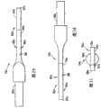
图7-16中所示的调整片部件16是两部分组成的结构,其由包括杆部60的内部和限定了远端部62的外部形成。杆部60通常适合于封住刺入件并保持刺入件的无菌直到刺血针装置10启用。远端部62被形成得用于封住护罩14向前远端50中的远端开口52,并适于保持护罩14和外壳12相对于彼此轴向移动。远端部62还符合人体工程学地形成得使得使用者容易操纵调整片部件16并施加必需的断开力以使调整片部件16断开与驱动机构和/或包含在壳主体20中的刺入件的接合。远端部62包括抓持部,诸如桨状件64,适于由使用者抓持以施加必需的断开力。在调整片部件16的本实施例中,远端部62包括适于与护罩14配合的悬垂裙部66(通常封住或封闭护罩14)。桨状件64具有倒圆的远端67。The
桨状件64的相对侧显示出这样的轮廓,该轮廓引导使用者关于将其指尖放置在桨状件64上的哪个位置,并且从视觉上以及从触觉上指示使用者如何向调整片部件16施加断开力以断开调整片部件16与驱动机构和/或刺入件之间的连接。通过桨状件64的相对弯曲的相对边缘68、70形成该轮廓。相对弯曲的相对边缘68、70关于基本上横向地穿过桨状件64的平面(即,通常垂直于显示出图13中所示的横截面的平面)形成通常为非对称的横截面。图12和13中所示的横截面通常是波形或S形的。总之,除提供关于使用者应将其指尖放置在桨状件64上的哪个位置的视觉和触觉提示以外,桨状件64的轮廓还在视觉上和触觉上指示使用者应将旋转力施加于桨状件64以帮助调整片部件16与设在壳主体20中的驱动机构和/或刺入件相分离。断开力被确定为组合的旋转或“扭转”力和“拔”力,用于断开调整片部件16与驱动机构和/或刺入件之间的连接。The opposite side of the
具体地,如图7-9中所示的,在刺血针装置10的预使用状态下,裙部66通常封住或封闭护罩14的远端部分。这不仅有助于装置中的刺入件的无菌,而且还保持护罩14远端50的前表面的无菌,该前表面在使用过程中接触患者的皮肤。裙部66还用于防止刺血针装置10的无意中驱动。如图14-16中所示的,裙部66是远端部62的整体部分并与桨状件64相连续。裙部66包括在调整片部件16与护罩14相连接时与壳主体20的远端22相接合的圆周边缘72,其用于防止护罩14非有意地位移到外壳12中且导致刺血针装置10的无意中驱动。优选地,外壳12、护罩14、以及调整片部件16全部由模制塑料材料制成,诸如医用级别塑料材料。裙部66也可作为如文中所述的任何其他实施例中的调整片部件16的部分而提供。Specifically, as shown in FIGS. 7-9 , in the pre-use state of
在替换实施例中,裙部66和/或壳主体20可包括用于帮助调整片部件与刺血针装置10脱离的结构。例如,如图14A中所示的,裙部66的圆周边缘72和壳主体20的远端22可包括用于帮助调整片部件与装置10脱离的相应结构。在图14A中所示的实施例中,圆周边缘72和远端22都形成有相应轮廓。在使用之前当裙部66与护罩14相接合时,圆周边缘72和远端22的相应轮廓配合以形成封闭结构。在脱离过程中,调整片部件16的旋转使得裙部66的圆周边缘72骑在远端22的有轮廓表面,从而形成或促成相应有轮廓表面之间的凸轮状接合,并帮助调整片部件16的向前或远端移动,辅助调整片部件16的脱离。In alternative embodiments, the
在操作中,桨状件64影响护罩14的驱动或移动,因此,通常影响刺血针装置10的驱动。圆周边缘或表面72被定位成例如通过接触而接合壳主体20的远端22,从而护罩14不能位移到壳主体20中以施加驱动设在壳主体20中的驱动机构所需的动作或力。因此,桨状件64是防止护罩14移动到壳主体20中(进而,移动到刺血针装置10中)的驱动抑制或影响装置。In operation, paddle 64 affects the actuation or movement of
具体地,参照图16,调整片部件16是两部分组成的结构,其由杆部60和远端部62形成,如前面描述的。杆部60可与远端部62相分离,如图16中所示的。杆部60包括远端74和近端76。近端76通常适合于连接于设置在外壳12中的驱动机构和/或刺入件,例如与驱动机构的一部分整体连接。远端74限定渐缩部分78以允许远端74被插入到远端部62中的接收槽80中,并且,更具体地,被接收在桨状件64中。远端74与接收槽80之间的接合是摩擦配合接合,并且远端74可与接收槽80脱离,从而分离杆部60与远端部62。在渐缩部分78的所有实施例中,78中垂直于通过远端74的中心轴线截得的横截面产生非圆形截面,以使杆部60相对于远端部62和桨状件64的转动被防止或者至少被限制。In particular, referring to FIG. 16, the
参见图17-22,其中示出了具有调整片部件16a的第二实施例的刺血针装置10。调整片部件16a的结构与上述调整片部件16类似,具有两个细微的变化。第一,调整片部件16a省略了远端部62a的裙部66。另外,桨状部分64a的整体形状为椭圆形或者扁长的。调整片部件16a的第二实施例说明裙部66是非强制性的并且根据本发明可露出护罩14。但是,如上所述,裙部66可与上述关于调整片部件16的实施例中的任何一个实施例结合使用或者从如图17-22所示的任何实施例中省略。17-22, there is shown a second embodiment of a
调整片部件16a还包括杆部60a和远端部62a,杆部60a和远端部62a以上述关于调整片部件16的第一实施例的方式相互分离。如在图20和21中所示,桨状件64a还表现由桨状件64a的相对弯曲边缘68a、70a形成或者限定的外形。The
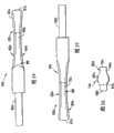
图23-26示出了调整片部件16b的第三实施例。调整片部件16b的第三实施例的结构基本上与调整片部件16a的第二实施例相同,并且在桨状件64b的形状和成形方面改变。在该实施例中,桨状件64b通常也为椭圆形、扁长形或者卵形。但是,桨状件64b的相对顶面和底面82、84的形成方式与调整片部件16、16a的上述实施例略微不同。在该实施例中,桨状件64b的相对边缘68b、70b不是相对弯曲的,因此当看图26时可以明显地看出桨状件64b具有双边对称的横截面。以与壳主体20的侧部手指抓持凹口32相似的方式,有轮廓的侧部82、84通常被形成为手指抓持凹口。有轮廓的侧部82、84可限定双曲线的、抛物线的、半圆形的形状。由有轮廓的侧部82、84形成的手指抓持凹口通常是凹形的,例如是双曲线形状的,以自然地适合使用者的指尖。桨状件64b的每个有轮廓的侧部82、84均包括一个或多个突起的手指抓持调整片86,用于改进桨状件64b与使用者指尖之间的摩擦特征。杆部60b可以与调整片部件16、16a的前述实施例相似的方式可拆卸地连接于远端部62b。23-26 illustrate a third embodiment of the
图27-31示出了调整片部件16c的第四实施例。调整片部件16c的第四实施例以与调整片部件16a、16b的第二和第三实施例基本相似的方式构成,并且又是主要在桨状件64c的形状和成形上改变。在该实施例中,桨状件64c在平面图中通常是非对称的,并且桨状件64b的相对边缘68c、70c不是相对弯曲的。然而,相对边缘68c、70c限定了相对的纵向弯曲部分或凸出部分88,如图28中清楚示出的,这使得桨状件64c的总体形状是非对称的。相对的弯曲部分88通常是双曲线或椭圆形状的(即,凹形的),如图27和28中所示的。与前述实施例相反,桨状件64c的相对侧部82c、84c不具有轮廓并被形成为通常平坦的表面。每个相对侧部82c、84c均在其中限定一个或多个成形凹口90。如图28中所示的,凹口90可具有任何适合的形状,诸如三角形(即,多边形形状)。其他适合的形状包括圆形、半圆形、卵形或不对称形状。成形的凹口90通常取代设在前述桨状件64b上的突出手指抓持调整片86。杆部60c可以与调整片部件16、16a、16b的前述实施例相似的方式可拆卸地连接于远端部62c。27-31 illustrate a fourth embodiment of the
图32-36示出了调整片部件16d的第五实施例。该实施例基本与上面刚刚描述的调整片部件16c相似。在该实施例中,桨状件64d在平面图中通常也是非对称的,并且桨状件64d的相对边缘68d、70d不是相对弯曲的。然而,以与图27-31中所示的调整片部件16c相似的方式,相对边缘68d、70d限定了相对的纵向弯曲部分88d,如图32和33中示出的。与刚刚描述的调整片部件16c的实施例相反,桨状件64d的相对侧部82d、84d以与图23-36中所示且先前描述的调整片部件16b相似的方式形成有轮廓。以与壳主体20的侧部手指抓持凹口32相似的方式,有轮廓的侧部82d、84d通常被形成为手指抓持凹口。由有轮廓的侧部82d、84d形成的手指抓持凹口通常是凹形的,以自然地适合使用者的指尖。桨状件64b的每个有轮廓的侧部82d、84d均可包括一个或多个突起的手指抓持调整片(未示出),其可与图23-25中所示的突起的手指抓持调整片86相似,用于改进桨状件64d与使用者指尖之间的摩擦特征。杆部60d可以以与调整片部件16、16a、16b、16c的前述实施例相似的方式可拆卸地连接于远端部62d。32-36 illustrate a fifth embodiment of a tab member 16d. This embodiment is substantially similar to the
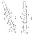
图37-40示出了调整片部件16e的第六实施例。在该实施例中,调整片部件16e在其整个长度上具有通常为圆柱形的形状,并且仅在杆部60e处减小横截面。远端62e不再形成有桨状件并且在其整个长度是通常为圆柱形的。在该实施例中,远端62e包括形成有由使用者抓持的相对手指抓持凹口94、96的远端抓持尖部92。以与壳主体20的侧部手指抓持凹口32相似的方式形成手指抓持凹口94、96,因此具有双曲线或椭圆形形状(例如,凹形),如图39中所示的。手指抓持凹口94、96通常是凹形的以自然地适合使用者的指尖。调整片部件16的远端62e进一步限定了设在杆部60e与手指抓持凹口94、96之间的中间部分或区域98。中间部分或区域98在其上限定了螺旋状的结构100。螺旋状的结构可称作螺旋状铲(helical sweep)、螺旋状键或者可被表示为外螺纹或者螺旋弹簧。螺旋状的结构100一般从抓持尖部92上的手指抓持凹口94、96正下方区域延伸到杆部60e。螺旋状的结构100为使用者提供视觉和触觉提示以指示使用者调整片部件16e应该转动以使得调整片部件16e脱开设置在壳体12内的致动机构和/或穿刺元件。螺旋状的结构100可用于指示使用者被调整片部件16e封闭的穿刺尖端可能是诸如针的尖穿刺元件,而不是具有切割边缘的刀状切割元件。中间部分16e可包括使得螺旋状的结构100平滑地过渡到设置在远端抓持尖部92上的平滑结构的过渡带102。37-40 illustrate a sixth embodiment of a
图41-44示出了调整片部件16f的第七实施例。调整片部件16f的成形基本上与上面参照图37-40所示的调整片部件16e的成形基本相同,细微的差别之处在于,螺旋状的结构100f在中间部分98f上的形成方式。螺旋状的结构100f与在图37-41中所示的中间部分98上的螺旋状的结构100相比沿着中间部分98f在纵向上进一步渐缩。另外,中间部分98f可省略上面参照图37-41所述的过渡带102,并且直接或者陡地与所述抓持尖部92f相连。41-44 illustrate a seventh embodiment of a
图45-48示出了调整片部件16g的第八实施例。调整片部件16g基本上与上述调整片部件16f相同,具有细微的变化。首先,调整片部件16g包括形成在每一个手指抓持凹口94g、96g上的一个或者多个突出的手指抓持调整片104。手指抓持凹口94g、96g类似双曲线或者椭圆形(凹入)表面。另外,中间部分98g上的螺旋状的结构100g与调整片部件16f中相比从抓持尖部92g更平滑地渐缩。最后,远端部分62g的倒圆远端67g比上述调整片部件16f的端部62f上的相应远端67f略微尖些(即,倒圆很小)。45-48 illustrate an eighth embodiment of a
图49和50示出了本发明所涉及的刺血针装置10a、10b的两个备选实施例。刺血针装置10a、10b主要在手指抓持凹口32a、32b的成形方面与上述刺血针装置10不同。在图49中,在壳体20a的相对侧面28a、30a中的手指抓持凹口32a仍然基本上为凹形凹陷部分或者槽以容纳刺血针装置10a的使用者手指尖。但是,现在手指抓持凹口32a过渡到从手指抓持凹口32a过渡到壳体20a的近端24a的壳体20a的基本上为圆柱形的部分。手指抓持凹口32a还可采用在上述壳体20a的相对侧面28a、30a中的双曲线、抛物线或者半圆形凹口、凹槽或凹陷部分。在图50中,手指抓持凹口32b过渡到从手指抓持凹口32b过渡到壳体20a的远端22b的壳体20b的基本上为圆柱形的部分,或者以如图9中所示的相反方式。49 and 50 illustrate two alternative embodiments of
尽管已经参照刺血针装置及其无菌调整片元件对本发明进行了描述,但是本领域技术人员可在不脱离本发明保护范围的情况下对本发明进行变型和变化。因此,本发明由后面的权利要求限定的,并且所有落入权利要求等同的范围内的本发明的变化都包含在它们的范围内。Although the invention has been described with reference to a lancet device and its sterile tab elements, variations and variations of the invention may be made by those skilled in the art without departing from the scope of the invention. Accordingly, the invention is defined by the following claims and all changes of the invention which come within the range of equivalency of the claims are intended to be embraced within their scope.
Claims (9)
Applications Claiming Priority (7)
| Application Number | Priority Date | Filing Date | Title |
|---|---|---|---|
| US63179504P | 2004-11-30 | 2004-11-30 | |
| US63184604P | 2004-11-30 | 2004-11-30 | |
| US60/631,846 | 2004-11-30 | ||
| US60/631,795 | 2004-11-30 | ||
| US11/123,849 | 2005-05-06 | ||
| US11/123,849US9380975B2 (en) | 2004-05-07 | 2005-05-06 | Contact activated lancet device |
| PCT/US2005/040589WO2006060128A2 (en) | 2004-11-30 | 2005-11-09 | Lancet device |
Related Child Applications (1)
| Application Number | Title | Priority Date | Filing Date |
|---|---|---|---|
| CN201210332282.6ADivisionCN102934996B (en) | 2004-11-30 | 2005-11-09 | Lancet device |
Publications (2)
| Publication Number | Publication Date |
|---|---|
| CN101090667A CN101090667A (en) | 2007-12-19 |
| CN101090667Btrue CN101090667B (en) | 2012-09-26 |
Family
ID=35929863
Family Applications (2)
| Application Number | Title | Priority Date | Filing Date |
|---|---|---|---|
| CN2005800449289AActiveCN101090667B (en) | 2004-11-30 | 2005-11-09 | Lancet device |
| CN201210332282.6AActiveCN102934996B (en) | 2004-11-30 | 2005-11-09 | Lancet device |
Family Applications After (1)
| Application Number | Title | Priority Date | Filing Date |
|---|---|---|---|
| CN201210332282.6AActiveCN102934996B (en) | 2004-11-30 | 2005-11-09 | Lancet device |
Country Status (10)
| Country | Link |
|---|---|
| US (8) | US9380975B2 (en) |
| EP (3) | EP2898829B1 (en) |
| JP (1) | JP5022225B2 (en) |
| CN (2) | CN101090667B (en) |
| AU (1) | AU2005310258B2 (en) |
| BR (1) | BRPI0518685B8 (en) |
| CA (2) | CA2589380C (en) |
| ES (3) | ES2650591T3 (en) |
| PL (2) | PL3323344T3 (en) |
| WO (1) | WO2006060128A2 (en) |
Families Citing this family (189)
| Publication number | Priority date | Publication date | Assignee | Title |
|---|---|---|---|---|
| US6036924A (en) | 1997-12-04 | 2000-03-14 | Hewlett-Packard Company | Cassette of lancet cartridges for sampling blood |
| US6391005B1 (en) | 1998-03-30 | 2002-05-21 | Agilent Technologies, Inc. | Apparatus and method for penetration with shaft having a sensor for sensing penetration depth |
| US8641644B2 (en) | 2000-11-21 | 2014-02-04 | Sanofi-Aventis Deutschland Gmbh | Blood testing apparatus having a rotatable cartridge with multiple lancing elements and testing means |
| DE10057832C1 (en) | 2000-11-21 | 2002-02-21 | Hartmann Paul Ag | Blood analysis device has syringe mounted in casing, annular mounting carrying needles mounted behind test strip and being swiveled so that needle can be pushed through strip and aperture in casing to take blood sample |
| US9795747B2 (en) | 2010-06-02 | 2017-10-24 | Sanofi-Aventis Deutschland Gmbh | Methods and apparatus for lancet actuation |
| US7749174B2 (en) | 2001-06-12 | 2010-07-06 | Pelikan Technologies, Inc. | Method and apparatus for lancet launching device intergrated onto a blood-sampling cartridge |
| JP4272051B2 (en) | 2001-06-12 | 2009-06-03 | ペリカン テクノロジーズ インコーポレイテッド | Blood sampling apparatus and method |
| US7041068B2 (en) | 2001-06-12 | 2006-05-09 | Pelikan Technologies, Inc. | Sampling module device and method |
| US7344507B2 (en) | 2002-04-19 | 2008-03-18 | Pelikan Technologies, Inc. | Method and apparatus for lancet actuation |
| JP4209767B2 (en) | 2001-06-12 | 2009-01-14 | ペリカン テクノロジーズ インコーポレイテッド | Self-optimized cutting instrument with adaptive means for temporary changes in skin properties |
| US7981056B2 (en) | 2002-04-19 | 2011-07-19 | Pelikan Technologies, Inc. | Methods and apparatus for lancet actuation |
| EP1395185B1 (en) | 2001-06-12 | 2010-10-27 | Pelikan Technologies Inc. | Electric lancet actuator |
| WO2002101359A2 (en) | 2001-06-12 | 2002-12-19 | Pelikan Technologies, Inc. | Integrated blood sampling analysis system with multi-use sampling module |
| AU2002344825A1 (en) | 2001-06-12 | 2002-12-23 | Pelikan Technologies, Inc. | Method and apparatus for improving success rate of blood yield from a fingerstick |
| US8337419B2 (en) | 2002-04-19 | 2012-12-25 | Sanofi-Aventis Deutschland Gmbh | Tissue penetration device |
| US9226699B2 (en) | 2002-04-19 | 2016-01-05 | Sanofi-Aventis Deutschland Gmbh | Body fluid sampling module with a continuous compression tissue interface surface |
| US9427532B2 (en) | 2001-06-12 | 2016-08-30 | Sanofi-Aventis Deutschland Gmbh | Tissue penetration device |
| US7344894B2 (en) | 2001-10-16 | 2008-03-18 | Agilent Technologies, Inc. | Thermal regulation of fluidic samples within a diagnostic cartridge |
| US7297122B2 (en) | 2002-04-19 | 2007-11-20 | Pelikan Technologies, Inc. | Method and apparatus for penetrating tissue |
| US7648468B2 (en) | 2002-04-19 | 2010-01-19 | Pelikon Technologies, Inc. | Method and apparatus for penetrating tissue |
| US9795334B2 (en) | 2002-04-19 | 2017-10-24 | Sanofi-Aventis Deutschland Gmbh | Method and apparatus for penetrating tissue |
| US7229458B2 (en) | 2002-04-19 | 2007-06-12 | Pelikan Technologies, Inc. | Method and apparatus for penetrating tissue |
| US9248267B2 (en) | 2002-04-19 | 2016-02-02 | Sanofi-Aventis Deustchland Gmbh | Tissue penetration device |
| US7141058B2 (en) | 2002-04-19 | 2006-11-28 | Pelikan Technologies, Inc. | Method and apparatus for a body fluid sampling device using illumination |
| US7547287B2 (en) | 2002-04-19 | 2009-06-16 | Pelikan Technologies, Inc. | Method and apparatus for penetrating tissue |
| US7892183B2 (en) | 2002-04-19 | 2011-02-22 | Pelikan Technologies, Inc. | Method and apparatus for body fluid sampling and analyte sensing |
| US7563232B2 (en) | 2002-04-19 | 2009-07-21 | Pelikan Technologies, Inc. | Method and apparatus for penetrating tissue |
| US7410468B2 (en) | 2002-04-19 | 2008-08-12 | Pelikan Technologies, Inc. | Method and apparatus for penetrating tissue |
| US9314194B2 (en) | 2002-04-19 | 2016-04-19 | Sanofi-Aventis Deutschland Gmbh | Tissue penetration device |
| US8579831B2 (en) | 2002-04-19 | 2013-11-12 | Sanofi-Aventis Deutschland Gmbh | Method and apparatus for penetrating tissue |
| US7708701B2 (en) | 2002-04-19 | 2010-05-04 | Pelikan Technologies, Inc. | Method and apparatus for a multi-use body fluid sampling device |
| US8784335B2 (en) | 2002-04-19 | 2014-07-22 | Sanofi-Aventis Deutschland Gmbh | Body fluid sampling device with a capacitive sensor |
| US7331931B2 (en) | 2002-04-19 | 2008-02-19 | Pelikan Technologies, Inc. | Method and apparatus for penetrating tissue |
| US7524293B2 (en) | 2002-04-19 | 2009-04-28 | Pelikan Technologies, Inc. | Method and apparatus for penetrating tissue |
| US7481776B2 (en) | 2002-04-19 | 2009-01-27 | Pelikan Technologies, Inc. | Method and apparatus for penetrating tissue |
| US7976476B2 (en) | 2002-04-19 | 2011-07-12 | Pelikan Technologies, Inc. | Device and method for variable speed lancet |
| US7901362B2 (en) | 2002-04-19 | 2011-03-08 | Pelikan Technologies, Inc. | Method and apparatus for penetrating tissue |
| US7909778B2 (en) | 2002-04-19 | 2011-03-22 | Pelikan Technologies, Inc. | Method and apparatus for penetrating tissue |
| US7717863B2 (en) | 2002-04-19 | 2010-05-18 | Pelikan Technologies, Inc. | Method and apparatus for penetrating tissue |
| US7674232B2 (en) | 2002-04-19 | 2010-03-09 | Pelikan Technologies, Inc. | Method and apparatus for penetrating tissue |
| US7232451B2 (en) | 2002-04-19 | 2007-06-19 | Pelikan Technologies, Inc. | Method and apparatus for penetrating tissue |
| US7374544B2 (en) | 2002-04-19 | 2008-05-20 | Pelikan Technologies, Inc. | Method and apparatus for penetrating tissue |
| US7491178B2 (en) | 2002-04-19 | 2009-02-17 | Pelikan Technologies, Inc. | Method and apparatus for penetrating tissue |
| US8221334B2 (en) | 2002-04-19 | 2012-07-17 | Sanofi-Aventis Deutschland Gmbh | Method and apparatus for penetrating tissue |
| US7371247B2 (en) | 2002-04-19 | 2008-05-13 | Pelikan Technologies, Inc | Method and apparatus for penetrating tissue |
| US7291117B2 (en) | 2002-04-19 | 2007-11-06 | Pelikan Technologies, Inc. | Method and apparatus for penetrating tissue |
| US8702624B2 (en) | 2006-09-29 | 2014-04-22 | Sanofi-Aventis Deutschland Gmbh | Analyte measurement device with a single shot actuator |
| US8267870B2 (en) | 2002-04-19 | 2012-09-18 | Sanofi-Aventis Deutschland Gmbh | Method and apparatus for body fluid sampling with hybrid actuation |
| US7582099B2 (en) | 2002-04-19 | 2009-09-01 | Pelikan Technologies, Inc | Method and apparatus for penetrating tissue |
| US7381184B2 (en) | 2002-11-05 | 2008-06-03 | Abbott Diabetes Care Inc. | Sensor inserter assembly |
| US8574895B2 (en) | 2002-12-30 | 2013-11-05 | Sanofi-Aventis Deutschland Gmbh | Method and apparatus using optical techniques to measure analyte levels |
| DE602004003549T2 (en)* | 2003-02-11 | 2007-09-27 | Salvus Technology Ltd., Stradbroke | SAFETY PIN |
| US7850621B2 (en) | 2003-06-06 | 2010-12-14 | Pelikan Technologies, Inc. | Method and apparatus for body fluid sampling and analyte sensing |
| WO2006001797A1 (en) | 2004-06-14 | 2006-01-05 | Pelikan Technologies, Inc. | Low pain penetrating |
| EP1635700B1 (en) | 2003-06-13 | 2016-03-09 | Sanofi-Aventis Deutschland GmbH | Apparatus for a point of care device |
| US20190357827A1 (en) | 2003-08-01 | 2019-11-28 | Dexcom, Inc. | Analyte sensor |
| US8282576B2 (en) | 2003-09-29 | 2012-10-09 | Sanofi-Aventis Deutschland Gmbh | Method and apparatus for an improved sample capture device |
| EP1680014A4 (en) | 2003-10-14 | 2009-01-21 | Pelikan Technologies Inc | METHOD AND DEVICE FOR A VARIABLE USER INTERFACE |
| USD902408S1 (en) | 2003-11-05 | 2020-11-17 | Abbott Diabetes Care Inc. | Analyte sensor control unit |
| US8668656B2 (en) | 2003-12-31 | 2014-03-11 | Sanofi-Aventis Deutschland Gmbh | Method and apparatus for improving fluidic flow and sample capture |
| US7822454B1 (en) | 2005-01-03 | 2010-10-26 | Pelikan Technologies, Inc. | Fluid sampling device with improved analyte detecting member configuration |
| WO2009048462A1 (en) | 2007-10-09 | 2009-04-16 | Dexcom, Inc. | Integrated insulin delivery system with continuous glucose sensor |
| US9066688B2 (en)* | 2004-05-07 | 2015-06-30 | Becton, Dickinson And Company | Contact activated lancet device |
| US9380975B2 (en)* | 2004-05-07 | 2016-07-05 | Becton, Dickinson And Company | Contact activated lancet device |
| WO2006011062A2 (en) | 2004-05-20 | 2006-02-02 | Albatros Technologies Gmbh & Co. Kg | Printable hydrogel for biosensors |
| WO2005120365A1 (en) | 2004-06-03 | 2005-12-22 | Pelikan Technologies, Inc. | Method and apparatus for a fluid sampling device |
| AU2005272621B2 (en)* | 2004-08-13 | 2010-11-11 | Becton, Dickinson And Company | Retractable needle syringe assembly |
| US10226207B2 (en) | 2004-12-29 | 2019-03-12 | Abbott Diabetes Care Inc. | Sensor inserter having introducer |
| US9259175B2 (en) | 2006-10-23 | 2016-02-16 | Abbott Diabetes Care, Inc. | Flexible patch for fluid delivery and monitoring body analytes |
| US8333714B2 (en) | 2006-09-10 | 2012-12-18 | Abbott Diabetes Care Inc. | Method and system for providing an integrated analyte sensor insertion device and data processing unit |
| US9398882B2 (en) | 2005-09-30 | 2016-07-26 | Abbott Diabetes Care Inc. | Method and apparatus for providing analyte sensor and data processing device |
| US9572534B2 (en) | 2010-06-29 | 2017-02-21 | Abbott Diabetes Care Inc. | Devices, systems and methods for on-skin or on-body mounting of medical devices |
| US8512243B2 (en) | 2005-09-30 | 2013-08-20 | Abbott Diabetes Care Inc. | Integrated introducer and transmitter assembly and methods of use |
| US7697967B2 (en) | 2005-12-28 | 2010-04-13 | Abbott Diabetes Care Inc. | Method and apparatus for providing analyte sensor insertion |
| US8571624B2 (en) | 2004-12-29 | 2013-10-29 | Abbott Diabetes Care Inc. | Method and apparatus for mounting a data transmission device in a communication system |
| US9743862B2 (en) | 2011-03-31 | 2017-08-29 | Abbott Diabetes Care Inc. | Systems and methods for transcutaneously implanting medical devices |
| US20090105569A1 (en) | 2006-04-28 | 2009-04-23 | Abbott Diabetes Care, Inc. | Introducer Assembly and Methods of Use |
| US7883464B2 (en) | 2005-09-30 | 2011-02-08 | Abbott Diabetes Care Inc. | Integrated transmitter unit and sensor introducer mechanism and methods of use |
| US9788771B2 (en) | 2006-10-23 | 2017-10-17 | Abbott Diabetes Care Inc. | Variable speed sensor insertion devices and methods of use |
| US8029441B2 (en) | 2006-02-28 | 2011-10-04 | Abbott Diabetes Care Inc. | Analyte sensor transmitter unit configuration for a data monitoring and management system |
| US7731657B2 (en) | 2005-08-30 | 2010-06-08 | Abbott Diabetes Care Inc. | Analyte sensor introducer and methods of use |
| US8652831B2 (en) | 2004-12-30 | 2014-02-18 | Sanofi-Aventis Deutschland Gmbh | Method and apparatus for analyte measurement test time |
| US8235950B2 (en)* | 2005-02-03 | 2012-08-07 | Salvus Technology GmbH | Safety needle |
| US8597255B2 (en)* | 2005-02-03 | 2013-12-03 | Salvus Technology Limited | Safety needle |
| US8827961B2 (en)* | 2005-02-03 | 2014-09-09 | West Pharmaceutical Services, Inc. | Safety needle |
| AU2006217781B2 (en)* | 2005-02-25 | 2010-09-16 | Salvus Technology Limited | Safety needle accessory |
| EP1868491B1 (en)* | 2005-03-24 | 2011-05-18 | Roche Diagnostics GmbH | Analyzing means with lancet and test element |
| WO2006110573A1 (en)* | 2005-04-07 | 2006-10-19 | Becton, Dickinson And Company | Trigger activated lancet |
| PL2425776T3 (en) | 2005-04-07 | 2013-12-31 | Becton Dickinson Co | Lancet device |
| WO2006110572A2 (en)* | 2005-04-07 | 2006-10-19 | Becton, Dickinson And Company | Finger activated lancet device |
| CN101179991B (en)* | 2005-04-07 | 2010-11-03 | 贝克顿·迪金森公司 | Push activation lancet device |
| US9521968B2 (en) | 2005-09-30 | 2016-12-20 | Abbott Diabetes Care Inc. | Analyte sensor retention mechanism and methods of use |
| CA2636034A1 (en) | 2005-12-28 | 2007-10-25 | Abbott Diabetes Care Inc. | Medical device insertion |
| US11298058B2 (en) | 2005-12-28 | 2022-04-12 | Abbott Diabetes Care Inc. | Method and apparatus for providing analyte sensor insertion |
| GB2434542A (en)* | 2006-01-31 | 2007-08-01 | Owen Mumford Ltd | Single-use skin pricking device |
| EP1852069B1 (en)* | 2006-05-04 | 2015-06-17 | Roche Diagnostics GmbH | System for sampling blood from a body part |
| WO2007129757A1 (en)* | 2006-05-10 | 2007-11-15 | Panasonic Corporation | Piercing instrument and piercing needle cartridge |
| USD569517S1 (en)* | 2006-06-07 | 2008-05-20 | Bradley Wilkinson | Lancet device |
| USD569975S1 (en)* | 2006-06-07 | 2008-05-27 | Becton Dickinson Co | Lancet device |
| DE102007005407A1 (en) | 2007-02-03 | 2008-08-07 | Fresenius Kabi Deutschland Gmbh | Cap for a container for holding medical fluids and container for receiving medical fluids |
| WO2008150917A1 (en) | 2007-05-31 | 2008-12-11 | Abbott Diabetes Care, Inc. | Insertion devices and methods |
| US9226748B2 (en)* | 2007-07-26 | 2016-01-05 | Alpha Scientific Corporation | Surgical suturing device, method and tools used therewith |
| GB0719876D0 (en)* | 2007-10-11 | 2007-11-21 | Weston Terence E | Safety needle |
| EP2265324B1 (en) | 2008-04-11 | 2015-01-28 | Sanofi-Aventis Deutschland GmbH | Integrated analyte measurement system |
| US8932314B2 (en)* | 2008-05-09 | 2015-01-13 | Lifescan Scotland Limited | Prime and fire lancing device with contacting bias drive and method |
| USD586916S1 (en) | 2008-05-09 | 2009-02-17 | Lifescan Scotland, Ltd. | Handheld lancing device |
| US20090281457A1 (en)* | 2008-05-09 | 2009-11-12 | Lifescan Soctland Ltd. | Prime and fire lancing device with non-contacting bias drive and method |
| USD586465S1 (en) | 2008-05-09 | 2009-02-10 | Lifescan Scotland Limited | Handheld lancing device |
| US8454533B2 (en) | 2008-05-09 | 2013-06-04 | Lifescan Scotland Limited | Lancing devices and methods |
| JP5386673B2 (en) | 2008-06-05 | 2014-01-15 | 株式会社ライトニックス | Puncture needle cartridge and puncture device |
| EP2337497A2 (en) | 2008-07-29 | 2011-06-29 | Facet Technologies, LLC | Lancets with improved coupling features and sterility caps |
| US9375169B2 (en) | 2009-01-30 | 2016-06-28 | Sanofi-Aventis Deutschland Gmbh | Cam drive for managing disposable penetrating member actions with a single motor and motor and control system |
| US9402544B2 (en) | 2009-02-03 | 2016-08-02 | Abbott Diabetes Care Inc. | Analyte sensor and apparatus for insertion of the sensor |
| US8262685B2 (en)* | 2009-03-27 | 2012-09-11 | Nipro Corporation | Disposable lancing device |
| JP5267870B2 (en)* | 2009-03-27 | 2013-08-21 | ニプロ株式会社 | Disposable blood collection device |
| USD611602S1 (en)* | 2009-05-11 | 2010-03-09 | Facet Technologies, Llc | Lancing device |
| US20110040316A1 (en)* | 2009-08-17 | 2011-02-17 | Sanford Research/USD | Method and Apparatus for a Single Handed Squeeze Lancet |
| EP3001194B1 (en) | 2009-08-31 | 2019-04-17 | Abbott Diabetes Care, Inc. | Medical devices and methods |
| WO2011041531A1 (en) | 2009-09-30 | 2011-04-07 | Abbott Diabetes Care Inc. | Interconnect for on-body analyte monitoring device |
| US9044177B2 (en) | 2009-10-07 | 2015-06-02 | Asahi Polyslider Company, Limited | Lancet pricking device |
| US9055899B2 (en) | 2009-10-22 | 2015-06-16 | Facet Technologies, Llc | Lancing device with improved guidance assembly |
| USD924406S1 (en) | 2010-02-01 | 2021-07-06 | Abbott Diabetes Care Inc. | Analyte sensor inserter |
| LT3622883T (en) | 2010-03-24 | 2021-08-25 | Abbott Diabetes Care, Inc. | Medical device inserters and processes of inserting and using medical devices |
| AU2011230596A1 (en)* | 2010-03-24 | 2012-01-19 | Abbott Diabetes Care Inc. | Medical device inserters and processes of inserting and using medical devices |
| USD634426S1 (en) | 2010-04-08 | 2011-03-15 | Facet Technologies, Llc | Lancing device |
| US8965476B2 (en) | 2010-04-16 | 2015-02-24 | Sanofi-Aventis Deutschland Gmbh | Tissue penetration device |
| EP2382921A1 (en) | 2010-04-30 | 2011-11-02 | Roche Diagnostics GmbH | Lancing device with automatic disengagement |
| US11064921B2 (en) | 2010-06-29 | 2021-07-20 | Abbott Diabetes Care Inc. | Devices, systems and methods for on-skin or on-body mounting of medical devices |
| US8556855B2 (en) | 2010-07-22 | 2013-10-15 | Becton, Dickinson And Company | Dual chamber syringe with retractable needle |
| US8556854B2 (en) | 2010-07-22 | 2013-10-15 | Becton, Dickinson And Company | Dual chamber syringe with retractable needle |
| US8721599B2 (en) | 2010-07-22 | 2014-05-13 | Becton, Dickinson And Company | Dual chamber passive retraction needle syringe |
| US9550030B2 (en) | 2010-07-22 | 2017-01-24 | Becton, Dickinson And Company | Dual chamber syringe with retractable needle |
| USD645147S1 (en) | 2010-11-11 | 2011-09-13 | Facet Technologies, Llc | Safety lancet |
| USD645148S1 (en) | 2010-11-11 | 2011-09-13 | Facet Technologies, Llc | Safety lancet |
| EP2697650B1 (en) | 2011-04-15 | 2020-09-30 | Dexcom, Inc. | Advanced analyte sensor calibration and error detection |
| CN102370487A (en)* | 2011-09-09 | 2012-03-14 | 天津华鸿科技有限公司 | Blood taking needle device |
| EP2713879B1 (en) | 2011-12-11 | 2017-07-26 | Abbott Diabetes Care, Inc. | Analyte sensor devices, connections, and methods |
| DK2802261T3 (en)* | 2012-01-10 | 2016-02-29 | Sanofi Aventis Deutschland | A cartridge for insertion into a meter, a meter for receiving a cartridge therein, and a system comprising a meter and a cartridge |
| US20130211289A1 (en) | 2012-01-25 | 2013-08-15 | Tasso, Inc. | Handheld Device for Drawing, Collecting, and Analyzing Bodily Fluid |
| GB2498772A (en)* | 2012-01-27 | 2013-07-31 | Owen Mumford Ltd | Lancing device moving lancet needle in longitudinal and lateral directions, lancet needle and lancing device with anti-recocking means |
| JP5298210B2 (en)* | 2012-02-08 | 2013-09-25 | 株式会社旭ポリスライダー | Lancet |
| US10646150B2 (en)* | 2013-03-12 | 2020-05-12 | Ascensia Diabetes Care Holdings Ag | Lancing device |
| EP3007623B1 (en)* | 2013-06-10 | 2019-02-20 | Facet Technologies, LLC | Lancet needle with alignment and retention notch |
| USD762298S1 (en) | 2013-09-10 | 2016-07-26 | Theranos, Inc. | Blood collection device |
| USD713958S1 (en)* | 2013-12-05 | 2014-09-23 | Becton, Dickinson And Company | Pen needle outer cover |
| USD742004S1 (en)* | 2014-02-18 | 2015-10-27 | “HTL-STREFA” Spólka Akcyjna | Skin incision device |
| CA157667S (en)* | 2014-03-31 | 2015-04-30 | Htl Strefa Spólka Akcyjna | Lancet device |
| US9919082B2 (en)* | 2014-07-09 | 2018-03-20 | H&H Medical Corporation | Pneumothorax medical treatment device |
| JP6640830B2 (en) | 2014-07-18 | 2020-02-05 | ベクトン・ディキンソン・アンド・カンパニーBecton, Dickinson And Company | Lancet device for removing first droplet |
| CN106999120B (en) | 2014-08-01 | 2021-05-14 | 塔索公司 | Devices, systems, and methods for gravity-enhanced microfluidic collection, handling, and delivery of liquids |
| TWM496457U (en)* | 2014-09-11 | 2015-03-01 | Biotest Medical Corp | Blood collection device with needle seat guiding structure |
| ES2760649T3 (en)* | 2015-02-24 | 2020-05-14 | Facet Tech Llc | Single-use compression lancing device |
| US10213139B2 (en) | 2015-05-14 | 2019-02-26 | Abbott Diabetes Care Inc. | Systems, devices, and methods for assembling an applicator and sensor control device |
| WO2016183493A1 (en) | 2015-05-14 | 2016-11-17 | Abbott Diabetes Care Inc. | Compact medical device inserters and related systems and methods |
| US9980747B2 (en)* | 2015-11-13 | 2018-05-29 | Argon Medical Devices, Inc. | Retractable centesis needle |
| CA3009328C (en) | 2015-12-21 | 2024-03-05 | Tasso, Inc. | Devices, systems and methods for actuation and retraction in fluid collection |
| EP4026488B1 (en) | 2015-12-30 | 2023-07-19 | Dexcom, Inc. | Transcutaneous analyte sensor systems and methods |
| USD813390S1 (en)* | 2016-01-15 | 2018-03-20 | Aspen Surgical Products, Inc. | Surgical scalpel blade attachment |
| JP7104026B2 (en) | 2016-08-24 | 2022-07-20 | ベクトン・ディキンソン・アンド・カンパニー | Device for taking blood samples |
| US11071478B2 (en) | 2017-01-23 | 2021-07-27 | Abbott Diabetes Care Inc. | Systems, devices and methods for analyte sensor insertion |
| US20180303510A1 (en)* | 2017-04-20 | 2018-10-25 | Elie Levy | Ergonomic Scalpel |
| JP6549185B2 (en) | 2017-06-16 | 2019-07-24 | 株式会社旭ポリスライダー | injector |
| EP4111949B1 (en) | 2017-06-23 | 2023-07-26 | Dexcom, Inc. | Transcutaneous analyte sensors, applicators therefor, and needle hub comprising anti-rotation feature |
| KR102090541B1 (en)* | 2017-09-29 | 2020-05-27 | 최임철 | Pressure-Activated Disposable Pain-Free Lancet |
| US20190120785A1 (en) | 2017-10-24 | 2019-04-25 | Dexcom, Inc. | Pre-connected analyte sensors |
| US11331022B2 (en) | 2017-10-24 | 2022-05-17 | Dexcom, Inc. | Pre-connected analyte sensors |
| US11179106B2 (en)* | 2018-03-16 | 2021-11-23 | Cardiac Pacemakers, Inc. | Wearable device to disposable patch connection via conductive adhesive |
| EP3801259B1 (en) | 2018-05-25 | 2023-07-19 | Becton, Dickinson and Company | Blood collection assembly with vibration module |
| USD926325S1 (en) | 2018-06-22 | 2021-07-27 | Dexcom, Inc. | Wearable medical monitoring device |
| JP7460607B2 (en) | 2018-09-14 | 2024-04-02 | タッソ インコーポレイテッド | Body fluid collection devices and related methods |
| EP3626291A1 (en)* | 2018-09-21 | 2020-03-25 | Regeneron Pharmaceuticals, Inc. | Needle shield grip device |
| BR112021015617A2 (en) | 2019-02-14 | 2021-10-05 | Becton, Dickinson And Company | CAPILLARY COLLECTOR WITH ROTATING CONNECTION |
| CA3126999A1 (en) | 2019-02-22 | 2020-08-27 | Deka Products Limited Partnership | Infusion set and inserter assembly systems and methods |
| BE1027338B1 (en)* | 2019-06-04 | 2021-01-14 | Inst Of Tropical Medicine | FINGER PRICKER COLLECTOR |
| USD1002852S1 (en) | 2019-06-06 | 2023-10-24 | Abbott Diabetes Care Inc. | Analyte sensor device |
| KR20220062395A (en)* | 2019-09-17 | 2022-05-16 | 벡톤 디킨슨 홀딩즈 피티이 엘티디. | Manual safety device, injection device comprising same, and method for manufacturing said injection device |
| US11134575B2 (en) | 2019-09-30 | 2021-09-28 | Gentherm Gmbh | Dual conductor laminated substrate |
| USD952148S1 (en)* | 2020-06-05 | 2022-05-17 | Medivena Sp. Z O.O. | Safety lancet |
| USD952146S1 (en)* | 2020-07-07 | 2022-05-17 | Medivena Sp. Z O.O. | Safety lancet |
| CA3188510A1 (en) | 2020-08-31 | 2022-03-03 | Vivek S. RAO | Systems, devices, and methods for analyte sensor insertion |
| USD999913S1 (en) | 2020-12-21 | 2023-09-26 | Abbott Diabetes Care Inc | Analyte sensor inserter |
| TWI749984B (en)* | 2021-01-04 | 2021-12-11 | 睿康生醫股份有限公司 | Disposable blood sampling safety needle structure and method capable of reducing tingling sensation |
| EP4362791A4 (en)* | 2021-06-29 | 2025-04-30 | Becton, Dickinson and Company | Capillary blood collection device |
| US20240315619A1 (en)* | 2021-06-29 | 2024-09-26 | Becton, Dickinson And Company | Blood Collection Kit With Blood Collection Devices of Multiple Sizes and Associated Sizing Systems and Methods |
| KR20240024244A (en)* | 2021-06-29 | 2024-02-23 | 백톤 디킨슨 앤드 컴퍼니 | Capillary Blood Collection Device |
| CN117597069A (en) | 2021-06-29 | 2024-02-23 | 贝克顿·迪金森公司 | Simulation device for capillary blood collection |
| CN117580506A (en)* | 2021-06-29 | 2024-02-20 | 贝克顿·迪金森公司 | capillary blood collection device |
| JP7735612B2 (en) | 2022-07-29 | 2025-09-08 | マドゥロ ディスカバリー,エルエルシ― | Improved Catheter Hub |
| EP4491118A1 (en) | 2023-07-13 | 2025-01-15 | Becton, Dickinson and Company | Collector accessory for small volume collection containers and related sample collection methods |
Citations (2)
| Publication number | Priority date | Publication date | Assignee | Title |
|---|---|---|---|---|
| US5314441A (en)* | 1992-10-16 | 1994-05-24 | International Technidyne Corporation | Disposable slicing lancet assembly |
| CN1264571A (en)* | 1999-02-23 | 2000-08-30 | 生命扫描有限公司 | Blood pricking device able to relieve pain |
Family Cites Families (115)
| Publication number | Priority date | Publication date | Assignee | Title |
|---|---|---|---|---|
| US3016847A (en) | 1956-04-30 | 1962-01-16 | Fmc Corp | Pie tamping and perforating mechanism |
| CH538277A (en) | 1970-09-04 | 1973-06-30 | Micromedic Systems Inc | Percutaneous blood test device |
| NL7117611A (en)* | 1970-12-21 | 1972-06-23 | ||
| JPS557477A (en) | 1978-07-04 | 1980-01-19 | Unitika Ltd | Laminate wrapping laminate whose gas shuttingg shuttinggoff property hardly deteriorates due to inflexion fatigue |
| US4431426A (en)* | 1979-08-20 | 1984-02-14 | Groshong Leroy E | Methods and apparatus for intravenous therapy and hyperalimentation |
| DE3011211A1 (en) | 1980-03-22 | 1981-10-01 | Clinicon Mannheim GmbH, 6800 Mannheim | BLOOD PLANT DEVICE FOR TAKING BLOOD FOR DIAGNOSTIC PURPOSES |
| US4375815A (en)* | 1981-03-23 | 1983-03-08 | Becton Dickinson And Company | Retractable lancet assembly |
| US4535769A (en) | 1981-03-23 | 1985-08-20 | Becton, Dickinson And Company | Automatic retractable lancet assembly |
| US4388925A (en) | 1981-03-23 | 1983-06-21 | Becton Dickinson And Company | Automatic retractable lancet assembly |
| US4449529A (en)* | 1981-11-18 | 1984-05-22 | Becton Dickinson And Company | Automatic retractable lancet assembly |
| US4577630A (en) | 1984-02-14 | 1986-03-25 | Becton, Dickinson And Co. | Reusable breach loading target pressure activated lancet firing device |
| US4635633A (en)* | 1984-12-17 | 1987-01-13 | Hufnagle Douglas R | Combination sterile pad support and lancet |
| US4627445A (en) | 1985-04-08 | 1986-12-09 | Garid, Inc. | Glucose medical monitoring system |
| JPS61286738A (en) | 1985-06-14 | 1986-12-17 | オ−デイオバイオニクス インコ−ポレイテツド | Medical system |
| US4653513A (en) | 1985-08-09 | 1987-03-31 | Dombrowski Mitchell P | Blood sampler |
| AU96973S (en)* | 1986-05-13 | 1987-07-02 | Acuhealth Pty Ltd | Self treatment acupuncture unit |
| GB8618578D0 (en) | 1986-07-30 | 1986-09-10 | Turner R C | Lancet device |
| US5048738A (en)* | 1986-11-21 | 1991-09-17 | Tom Cardamone | Interchangeable tape cutter |
| GB8710470D0 (en)* | 1987-05-01 | 1987-06-03 | Mumford Ltd Owen | Blood sampling devices |
| US4774964A (en)* | 1987-11-18 | 1988-10-04 | Applied Plastics Technology, Inc. | Disposable blood collection device |
| US4924879A (en) | 1988-10-07 | 1990-05-15 | Brien Walter J O | Blood lancet device |
| GB8924937D0 (en) | 1989-11-04 | 1989-12-28 | Owen Mumford Ltd | Improvements relating to blood sampling devices |
| US4994068A (en) | 1989-11-24 | 1991-02-19 | Unidex, Inc. | Combination sterile pad support and lancet containing lancet disposal element |
| US5114404A (en)* | 1990-07-24 | 1992-05-19 | Paxton Gerald R | Multifunctional retractable needle type general purpose disabling syringe having enhanced safety features and related method of operation |
| US5167641A (en)* | 1991-05-29 | 1992-12-01 | Arnis, Inc. | Auto-retracting needle injector system |
| CA2123400A1 (en) | 1991-11-12 | 1993-05-27 | Urs A. Ramel | Lancet device |
| GB9200219D0 (en)* | 1992-01-07 | 1992-02-26 | Medimech Int Ltd | Automatic injectors |
| US5261880A (en)* | 1992-03-10 | 1993-11-16 | Injectimed, Inc. | Single use syringes with second use lockout |
| US5269765A (en)* | 1992-03-10 | 1993-12-14 | Injectimed, Inc. | Methods of manufacture of safety sleeves for medical injection devices |
| US6290683B1 (en)* | 1992-04-29 | 2001-09-18 | Mali-Tech Ltd. | Skin piercing needle assembly |
| US5318583A (en) | 1992-05-05 | 1994-06-07 | Ryder International Corporation | Lancet actuator mechanism |
| PL169210B1 (en) | 1992-08-03 | 1996-06-28 | Przed Zagraniczne Htl | Puncturing device |
| JPH06238140A (en) | 1993-02-18 | 1994-08-30 | Toto Ltd | Filter membrane |
| US5540664A (en)* | 1993-05-27 | 1996-07-30 | Washington Biotech Corporation | Reloadable automatic or manual emergency injection system |
| DE4320463A1 (en) | 1993-06-21 | 1994-12-22 | Boehringer Mannheim Gmbh | Blood lancet device for drawing blood for diagnostic purposes |
| US5439473A (en) | 1993-12-13 | 1995-08-08 | Modulohm A/S | Safety lancet |
| US5478316A (en)* | 1994-02-02 | 1995-12-26 | Becton, Dickinson And Company | Automatic self-injection device |
| GB9422260D0 (en) | 1994-11-04 | 1994-12-21 | Owen Mumford Ltd | Improvements relating to skin prickers |
| US5628765A (en) | 1994-11-29 | 1997-05-13 | Apls Co., Ltd. | Lancet assembly |
| US5836917A (en)* | 1995-01-10 | 1998-11-17 | Specialized Health Products, Inc. | Self retracting medical needle apparatus and methods |
| US5569286A (en) | 1995-03-29 | 1996-10-29 | Becton Dickinson And Company | Lancet assembly |
| USD387865S (en)* | 1995-03-29 | 1997-12-16 | Becton Dickinson And Company | Lancet |
| JP3025175B2 (en)* | 1995-05-18 | 2000-03-27 | 丸三食品株式会社 | Seasoning liquid container |
| US5571132A (en)* | 1995-06-06 | 1996-11-05 | International Technidyne Corporation | Self activated finger lancet |
| KR0135178Y1 (en) | 1995-06-26 | 1999-03-20 | 김인환 | Blood collection lancet |
| US5643306A (en) | 1996-03-22 | 1997-07-01 | Stat Medical Devices Inc. | Disposable lancet |
| GB9616953D0 (en)* | 1996-08-13 | 1996-09-25 | Owen Mumford Ltd | Improvements relating to skin prickers |
| US5800395A (en)* | 1996-12-05 | 1998-09-01 | Mdc Investment Holdings, Inc. | Medical device with retractable needle |
| US20070142776A9 (en)* | 1997-02-05 | 2007-06-21 | Medtronic Minimed, Inc. | Insertion device for an insertion set and method of using the same |
| GB9708512D0 (en)* | 1997-04-28 | 1997-06-18 | Owen Mumford Ltd | Improvements relating to skin prickers |
| US5984940A (en) | 1997-05-29 | 1999-11-16 | Atrion Medical Products, Inc. | Lancet device |
| DE69822487T2 (en) | 1997-06-02 | 2005-03-24 | Paul Viranyi | BRACKET OF LANZETTS TO POINT UP THE SKIN |
| GB9713077D0 (en)* | 1997-06-21 | 1997-08-27 | Owen Mumford Ltd | Improvements relating to skin prickers |
| US6569115B1 (en)* | 1997-08-28 | 2003-05-27 | Mdc Investment Holdings, Inc. | Pre-filled retractable needle injection device |
| US5964718A (en) | 1997-11-21 | 1999-10-12 | Mercury Diagnostics, Inc. | Body fluid sampling device |
| JP4194754B2 (en)* | 1998-01-12 | 2008-12-10 | モルソエ,クラウス | Syringe |
| US5908434A (en) | 1998-02-13 | 1999-06-01 | Schraga; Steven | Lancet device |
| US5957895A (en)* | 1998-02-20 | 1999-09-28 | Becton Dickinson And Company | Low-profile automatic injection device with self-emptying reservoir |
| US6053930A (en) | 1998-05-11 | 2000-04-25 | Ruppert; Norbert | Single use lancet assembly |
| SE9803662D0 (en)* | 1998-10-26 | 1998-10-26 | Pharmacia & Upjohn Ab | autoinjector |
| US6197040B1 (en)* | 1999-02-23 | 2001-03-06 | Lifescan, Inc. | Lancing device having a releasable connector |
| SG85117A1 (en) | 1999-06-18 | 2001-12-19 | Surgilance Pte Ltd | Lancet assembly |
| US6168606B1 (en) | 1999-11-10 | 2001-01-02 | Palco Labs, Inc. | Single-use lancet device |
| PL189108B1 (en) | 1999-09-06 | 2005-06-30 | Htl Strefa Sp Z Oo | Puncturing device |
| USD444557S1 (en)* | 1999-10-19 | 2001-07-03 | Facet Technologies, Llc | Lancing device |
| US6283982B1 (en)* | 1999-10-19 | 2001-09-04 | Facet Technologies, Inc. | Lancing device and method of sample collection |
| CA2287757A1 (en) | 1999-10-29 | 2001-04-29 | Medical Plastic Devices M.P.D. Inc. | Disposable lancet |
| US6258112B1 (en) | 1999-11-02 | 2001-07-10 | Steven Schraga | Single use lancet assembly |
| US6248120B1 (en) | 2000-01-10 | 2001-06-19 | P. Z. “HTL” Spolka Akcyjna | Puncturing device |
| PL191428B1 (en)* | 2000-04-06 | 2006-05-31 | Htl Strefa Sp Z Oo | Puncturing depth adjusting assembly for puncturing devices |
| DE10030410C1 (en)* | 2000-06-21 | 2002-01-24 | Roche Diagnostics Gmbh | Blood lancet device for drawing blood for diagnostic purposes |
| USD445598S1 (en)* | 2000-07-25 | 2001-07-31 | Lion Licensing, Ltd. | Display stand |
| DE10053974A1 (en)* | 2000-10-31 | 2002-05-29 | Roche Diagnostics Gmbh | Blood collection system |
| US6514270B1 (en) | 2000-11-10 | 2003-02-04 | Steven Schraga | Single use lancet device |
| US7044931B2 (en)* | 2000-12-13 | 2006-05-16 | Hypoguard Usa Inc. | Syringe with retractable needle assembly |
| US6491709B2 (en)* | 2000-12-22 | 2002-12-10 | Becton, Dickinson And Company | Alternate-site lancer |
| US6540763B2 (en) | 2001-02-20 | 2003-04-01 | Medisys Asia Pacific Pte Ltd. | Lancet device with retractable sharps member |
| EP1247489B1 (en) | 2001-04-04 | 2007-06-13 | HTL Strefa Spolka z o.o. | Blood sampling device |
| CN1380042A (en) | 2001-04-13 | 2002-11-20 | “Pzhtl”股份有限公司 | Puncture device |
| CN1332632C (en) | 2001-07-11 | 2007-08-22 | 爱科来株式会社 | Lancets and Piercing Devices |
| US8100857B2 (en)* | 2001-07-25 | 2012-01-24 | B. Braun Melsungen Ag | Method and apparatus for indicating or covering a percutaneous puncture site |
| AU2002319694B8 (en)* | 2001-07-25 | 2008-10-23 | B. Braun Melsungen Ag | Method and apparatus for indicating or covering a percutaneous puncture site |
| DE20114658U1 (en)* | 2001-09-05 | 2001-11-15 | WILDEN Engineering- und Vertriebsgesellschaft mbH, 92536 Pfreimd | Lancet for taking blood |
| US6984223B2 (en)* | 2001-11-13 | 2006-01-10 | Becton, Dickinson And Company | Needle safety device |
| KR20030042393A (en) | 2001-11-22 | 2003-05-28 | 신백식 | A disposal lancet |
| US20030109895A1 (en)* | 2001-12-07 | 2003-06-12 | Taylor William C. | Keyed lancet with generic mounting compatibility |
| WO2003073936A2 (en) | 2002-03-06 | 2003-09-12 | 'htl Strefa' Sp. Z O.O. | A device for puncturing patient's skin |
| AU2003201346A1 (en) | 2002-03-20 | 2003-10-16 | Becton, Dickinson And Company | Needle shield assembly |
| US20040039407A1 (en) | 2002-04-29 | 2004-02-26 | Steven Schraga | Lancet device |
| CA2484876C (en)* | 2002-05-13 | 2011-11-22 | Becton, Dickinson And Company | Protease inhibitor sample collection system |
| DE10222235A1 (en) | 2002-05-16 | 2003-11-27 | Roche Diagnostics Gmbh | Blood Collection system |
| DE10223558A1 (en) | 2002-05-28 | 2003-12-11 | Roche Diagnostics Gmbh | System useful in withdrawing blood for diagnostic purposes, has housing, lancet guide and lancet drive provided with drive spring, cocking device, drive rotor and outputs side coupling mechanism |
| US6997913B2 (en) | 2002-06-07 | 2006-02-14 | Becton, Dickinson And Company | Needle safety device |
| US20030233074A1 (en)* | 2002-06-17 | 2003-12-18 | Shields Jack W. | IV access connectors for syringes with needles |
| US6852119B1 (en)* | 2002-09-09 | 2005-02-08 | Ramzi F. Abulhaj | Adjustable disposable lancet and method |
| WO2004039429A2 (en) | 2002-10-29 | 2004-05-13 | Palco Labs, Inc. | Single-use lancet device |
| TW586947B (en)* | 2002-12-02 | 2004-05-11 | Ming-Jeng Shiu | Safety device for injection and blood-drawing |
| JP4761701B2 (en)* | 2003-05-21 | 2011-08-31 | アークレイ株式会社 | Puncture device with adjustable puncture depth |
| USD499182S1 (en) | 2003-06-11 | 2004-11-30 | Palco Labs, Inc. | Single use lancet |
| PL207804B1 (en) | 2003-07-29 | 2011-02-28 | Htl Strefa Społka Z Ograniczoną Odpowiedzialnością | Piercing apparatus |
| US20050085840A1 (en) | 2003-10-15 | 2005-04-21 | Surgilance Pte Ltd | Lancet assembly |
| US20050159768A1 (en)* | 2004-01-15 | 2005-07-21 | Home Diagnostics, Inc. | Lancing device |
| US7604613B2 (en)* | 2004-01-20 | 2009-10-20 | Beckton, Dickinson And Company | Syringe having a retractable needle |
| KR101121072B1 (en) | 2004-05-07 | 2012-03-15 | 벡톤 디킨슨 앤드 컴퍼니 | Contact activated lancet device |
| US9066688B2 (en)* | 2004-05-07 | 2015-06-30 | Becton, Dickinson And Company | Contact activated lancet device |
| US9380975B2 (en)* | 2004-05-07 | 2016-07-05 | Becton, Dickinson And Company | Contact activated lancet device |
| US20060100655A1 (en)* | 2004-10-28 | 2006-05-11 | Koon-Wah Leong | Combined lancing and auxiliary device |
| USD532517S1 (en) | 2004-12-17 | 2006-11-21 | Becton, Dickinson And Company | Lancet device |
| USD538934S1 (en) | 2004-12-17 | 2007-03-20 | Becton, Dickinson And Company | Lancet device |
| US20070093760A1 (en)* | 2005-10-11 | 2007-04-26 | Wexler Michael R | Syringe with wound dressing material |
| WO2007047403A1 (en)* | 2005-10-13 | 2007-04-26 | Becton, Dickinson And Company | Disposable needle and hub assembly |
| JP4891276B2 (en)* | 2007-08-23 | 2012-03-07 | テルモ株式会社 | Puncture device |
| US8900190B2 (en)* | 2009-09-02 | 2014-12-02 | Medtronic Minimed, Inc. | Insertion device systems and methods |
| US8414539B1 (en)* | 2011-12-27 | 2013-04-09 | B. Braun Melsungen Ag | Needle tip guard for percutaneous entry needles |
| ES2842292T3 (en) | 2016-07-27 | 2021-07-13 | Greif Int Holding B V | High barrier polymer blend composition |
- 2005
- 2005-05-06USUS11/123,849patent/US9380975B2/enactiveActive
- 2005-11-09JPJP2007544359Apatent/JP5022225B2/enactiveActive
- 2005-11-09AUAU2005310258Apatent/AU2005310258B2/enactiveActive
- 2005-11-09PLPL17196624Tpatent/PL3323344T3/enunknown
- 2005-11-09EPEP15155765.9Apatent/EP2898829B1/enactiveActive
- 2005-11-09CACA2589380Apatent/CA2589380C/enactiveActive
- 2005-11-09CACA2941589Apatent/CA2941589C/enactiveActive
- 2005-11-09PLPL05847750Tpatent/PL1816960T3/enunknown
- 2005-11-09BRBRPI0518685Apatent/BRPI0518685B8/enactiveIP Right Grant
- 2005-11-09USUS11/270,330patent/US8048096B2/enactiveActive
- 2005-11-09EPEP05847750.6Apatent/EP1816960B1/enactiveActive
- 2005-11-09CNCN2005800449289Apatent/CN101090667B/enactiveActive
- 2005-11-09ESES15155765.9Tpatent/ES2650591T3/enactiveActive
- 2005-11-09ESES17196624Tpatent/ES2746365T3/enactiveActive
- 2005-11-09CNCN201210332282.6Apatent/CN102934996B/enactiveActive
- 2005-11-09EPEP17196624.5Apatent/EP3323344B1/enactiveActive
- 2005-11-09WOPCT/US2005/040589patent/WO2006060128A2/enactiveApplication Filing
- 2005-11-09ESES05847750.6Tpatent/ES2539012T3/enactiveActive
- 2010
- 2010-06-14USUS12/815,005patent/US9005233B2/enactiveActive
- 2010-06-14USUS12/815,090patent/US8906055B2/enactiveActive
- 2010-06-14USUS12/815,067patent/US10105087B2/enactiveActive
- 2011
- 2011-09-29USUS13/248,734patent/US9844330B2/ennot_activeExpired - Lifetime
- 2018
- 2018-09-20USUS16/136,562patent/US10842428B2/ennot_activeExpired - Lifetime
- 2020
- 2020-10-20USUS17/074,662patent/US20210030343A1/ennot_activeAbandoned
Patent Citations (2)
| Publication number | Priority date | Publication date | Assignee | Title |
|---|---|---|---|---|
| US5314441A (en)* | 1992-10-16 | 1994-05-24 | International Technidyne Corporation | Disposable slicing lancet assembly |
| CN1264571A (en)* | 1999-02-23 | 2000-08-30 | 生命扫描有限公司 | Blood pricking device able to relieve pain |
Non-Patent Citations (1)
| Title |
|---|
| 说明书第6页第2段、附图1. |
Also Published As
Similar Documents
| Publication | Publication Date | Title |
|---|---|---|
| CN101090667B (en) | Lancet device | |
| EP2135551B1 (en) | Contact activated lancet device | |
| US9066688B2 (en) | Contact activated lancet device | |
| CN106687040B (en) | First drop removal lancet device | |
| EP2263539B1 (en) | Contact activated lancet device | |
| AU2011235936B2 (en) | Lancet device | |
| AU2012202665B2 (en) | Contact activated lancet device |
Legal Events
| Date | Code | Title | Description |
|---|---|---|---|
| C06 | Publication | ||
| PB01 | Publication | ||
| C10 | Entry into substantive examination | ||
| SE01 | Entry into force of request for substantive examination | ||
| C14 | Grant of patent or utility model | ||
| GR01 | Patent grant |