CN101087571B - device and method for improving heart valve function - Google Patents
device and method for improving heart valve functionDownload PDFInfo
- Publication number
- CN101087571B CN101087571BCN2005800429675ACN200580042967ACN101087571BCN 101087571 BCN101087571 BCN 101087571BCN 2005800429675 ACN2005800429675 ACN 2005800429675ACN 200580042967 ACN200580042967 ACN 200580042967ACN 101087571 BCN101087571 BCN 101087571B
- Authority
- CN
- China
- Prior art keywords
- shape
- valve
- contact
- heart valve
- heart
- Prior art date
- Legal status (The legal status is an assumption and is not a legal conclusion. Google has not performed a legal analysis and makes no representation as to the accuracy of the status listed.)
- Expired - Fee Related
Links
Images


Classifications
- A—HUMAN NECESSITIES
- A61—MEDICAL OR VETERINARY SCIENCE; HYGIENE
- A61F—FILTERS IMPLANTABLE INTO BLOOD VESSELS; PROSTHESES; DEVICES PROVIDING PATENCY TO, OR PREVENTING COLLAPSING OF, TUBULAR STRUCTURES OF THE BODY, e.g. STENTS; ORTHOPAEDIC, NURSING OR CONTRACEPTIVE DEVICES; FOMENTATION; TREATMENT OR PROTECTION OF EYES OR EARS; BANDAGES, DRESSINGS OR ABSORBENT PADS; FIRST-AID KITS
- A61F2/00—Filters implantable into blood vessels; Prostheses, i.e. artificial substitutes or replacements for parts of the body; Appliances for connecting them with the body; Devices providing patency to, or preventing collapsing of, tubular structures of the body, e.g. stents
- A61F2/02—Prostheses implantable into the body
- A61F2/24—Heart valves ; Vascular valves, e.g. venous valves; Heart implants, e.g. passive devices for improving the function of the native valve or the heart muscle; Transmyocardial revascularisation [TMR] devices; Valves implantable in the body
- A61F2/2442—Annuloplasty rings or inserts for correcting the valve shape; Implants for improving the function of a native heart valve
- A61F2/2445—Annuloplasty rings in direct contact with the valve annulus
- A—HUMAN NECESSITIES
- A61—MEDICAL OR VETERINARY SCIENCE; HYGIENE
- A61F—FILTERS IMPLANTABLE INTO BLOOD VESSELS; PROSTHESES; DEVICES PROVIDING PATENCY TO, OR PREVENTING COLLAPSING OF, TUBULAR STRUCTURES OF THE BODY, e.g. STENTS; ORTHOPAEDIC, NURSING OR CONTRACEPTIVE DEVICES; FOMENTATION; TREATMENT OR PROTECTION OF EYES OR EARS; BANDAGES, DRESSINGS OR ABSORBENT PADS; FIRST-AID KITS
- A61F2220/00—Fixations or connections for prostheses classified in groups A61F2/00 - A61F2/26 or A61F2/82 or A61F9/00 or A61F11/00 or subgroups thereof
- A61F2220/0008—Fixation appliances for connecting prostheses to the body
- A—HUMAN NECESSITIES
- A61—MEDICAL OR VETERINARY SCIENCE; HYGIENE
- A61F—FILTERS IMPLANTABLE INTO BLOOD VESSELS; PROSTHESES; DEVICES PROVIDING PATENCY TO, OR PREVENTING COLLAPSING OF, TUBULAR STRUCTURES OF THE BODY, e.g. STENTS; ORTHOPAEDIC, NURSING OR CONTRACEPTIVE DEVICES; FOMENTATION; TREATMENT OR PROTECTION OF EYES OR EARS; BANDAGES, DRESSINGS OR ABSORBENT PADS; FIRST-AID KITS
- A61F2250/00—Special features of prostheses classified in groups A61F2/00 - A61F2/26 or A61F2/82 or A61F9/00 or A61F11/00 or subgroups thereof
- A61F2250/0004—Special features of prostheses classified in groups A61F2/00 - A61F2/26 or A61F2/82 or A61F9/00 or A61F11/00 or subgroups thereof adjustable
- A61F2250/0007—Special features of prostheses classified in groups A61F2/00 - A61F2/26 or A61F2/82 or A61F9/00 or A61F11/00 or subgroups thereof adjustable for adjusting length
Landscapes
- Health & Medical Sciences (AREA)
- Cardiology (AREA)
- Oral & Maxillofacial Surgery (AREA)
- Transplantation (AREA)
- Engineering & Computer Science (AREA)
- Biomedical Technology (AREA)
- Heart & Thoracic Surgery (AREA)
- Vascular Medicine (AREA)
- Life Sciences & Earth Sciences (AREA)
- Animal Behavior & Ethology (AREA)
- General Health & Medical Sciences (AREA)
- Public Health (AREA)
- Veterinary Medicine (AREA)
- Prostheses (AREA)
Abstract
Description
Translated fromChinese技术领域technical field
本发明总体上涉及改善心脏瓣膜的机能。更具体地说,本发明涉及一种用于治疗存在各种畸形和机能障碍的心脏瓣膜的装置和方法。The present invention generally relates to improving the function of heart valves. More particularly, the present invention relates to an apparatus and method for treating heart valves with various malformations and dysfunctions.
背景技术Background technique
有病的二尖瓣和三尖瓣经常需要替换或修复。所述二尖瓣和三尖瓣小叶或支撑索可能退化和衰弱,或者环带可能膨胀而导致瓣膜渗漏(闭锁不全)。所述小叶和索可能变得钙化且增厚,致使它们变得狭窄(堵塞向前流动)。最后,所述瓣膜依靠于所述索插入心室内。如果心室改变形状,则瓣膜支撑可能变得无机能,而且瓣膜可能渗漏。Diseased mitral and tricuspid valves often require replacement or repair. The mitral and tricuspid leaflets or struts may degenerate and weaken, or the annulus may dilate causing the valve to leak (insufficiency). The leaflets and cords may become calcified and thickened, causing them to narrow (block forward flow). Finally, the valve is inserted into the ventricle by means of the cord. If the ventricle changes shape, the valve support may become nonfunctional and the valve may leak.
在瓣膜修复时,有病的瓣膜保持在原位,然后进行外科手术来恢复其机能。有许多修复心脏瓣膜以恢复或改善其机能的方法。经常采用瓣环成形环来减小环带的尺寸。该环用于减小所述环带的直径,并使小叶正常地彼此相对。采用缝合术来将修复环与所述环带相连,并且帮助使该环带打皱襞。In valve repair, the diseased valve is left in place and surgery is performed to restore its function. There are many ways to repair heart valves to restore or improve their function. An annuloplasty ring is often used to reduce the size of the annulus. This ring serves to reduce the diameter of the annulus and to allow the leaflets to normally face each other. Sutures are used to connect the repair ring to the annulus and to help plicate the annulus.
根据另一方法,通过缝合方式或者利用夹子将小叶在其自由边处彼此相连。这意味着产生两个孔,即在小叶相连的两边上各产生一个孔。而后这两个孔可完全闭合。用夹子来将小叶彼此相连的实例公开于US 2004/0220593中。According to another method, the leaflets are connected to each other at their free edges by means of sutures or with clips. This means that two holes are created, one on each side where the leaflets are connected. The two holes can then be completely closed. An example of using clips to attach leaflets to each other is disclosed in US 2004/0220593.
在US 6,723,038中,公开了用于改善二尖瓣机能的装置。一种装置包括用于改善心脏瓣膜机能的夹板。该夹板包括一细长构件以及第一和第二固定构件,该细长构件被配置为横穿心室而定位,使得该细长构件的各端延伸穿过心脏的壁,所述第一和第二固定构件被配置为定位在心室的外部,并且与该细长构件的端部相连,以将该细长构件固定在横过该心室的位置。该第一固定构件包括一第一部分,该第一部分被配置为接触心脏靠近该瓣膜环带的第一区域,从而通过压缩心脏来改变瓣膜环带的形状。瓣膜环带形状的改变有利于恢复心脏机能。然而,使用该装置,该细长构件将被放置在血流中,因而患者将需要终身的抗血栓治疗,以防止在血流中形成血凝块。In US 6,723,038 a device for improving mitral valve function is disclosed. One device includes a splint for improving heart valve function. The splint includes an elongate member configured to be positioned across the ventricle such that each end of the elongate member extends through the wall of the heart, and first and second fixation members. Two fixation members are configured to be positioned outside of the ventricle and connected to the ends of the elongate member to secure the elongate member in position across the ventricle. The first fixation member includes a first portion configured to contact a first region of the heart proximate the valve annulus to thereby change the shape of the valve annulus by compressing the heart. Changes in the shape of the valve annulus are conducive to the restoration of cardiac function. However, with this device, the elongated member would be placed in the bloodstream, and the patient would require life-long antithrombotic therapy to prevent clots from forming in the bloodstream.
发明内容Contents of the invention
本发明的目的在于提供一种更容易实现的瓣膜修复,以便提供改善的心脏瓣膜机能。本发明的具体目的在于实现一种不阻碍血液流过心脏瓣膜的瓣膜修复。It is an object of the present invention to provide a more readily achievable valve repair in order to provide improved heart valve function. A particular object of the present invention is to achieve a valve repair that does not impede the flow of blood through the heart valve.
本发明的这些和其他目的是通过根据独立权利要求的装置和方法来实现的。本发明的优选实施例根据从属权利要求而变得明显。These and other objects of the invention are achieved by devices and methods according to the independent claims. Preferred embodiments of the invention are apparent from the dependent claims.
因此,提供一种用于改善心脏瓣膜机能的装置,该心脏瓣膜由包括环带、小叶和位于相邻小叶之间的至少第一连合和第二连合的瓣膜组织构成.该装置具有第一形状和第二形状,并且包括第一接触点和第二接触点,其中该装置处于第一形状时在所述第一接触点和第二接触点之间呈现的距离基本上对应于该心脏瓣膜的所述第一连合和第二连合之间的距离,该装置处于第二形状时在所述第一接触点和第二接触点之间呈现增加的距离.所述装置处于第一形状时被布置为插入该心脏瓣膜,以在该第一接触点和该第一连合处的瓣膜组织之间形成接触,以及在该第二接触点和该第二连合处的瓣膜组织之间形成接触.所述装置在被插入该心脏瓣膜时可从所述第一形状转变为所述第二形状,并且所述装置处于第二形状时被布置为大致沿其整个长度延伸在该第一接触点和第二接触点之间,并在整个心脏动作周期邻接该瓣膜组织.Accordingly, there is provided a device for improving the function of a heart valve consisting of valve tissue comprising an annulus, leaflets and at least a first commissure and a second commissure between adjacent leaflets. The device has a first a shape and a second shape, and comprising a first point of contact and a second point of contact, wherein the distance exhibited between the first point of contact and the second point of contact when the device is in the first shape substantially corresponds to that of the heart The distance between the first commissure and the second commissure of the valve, the device exhibits an increased distance between the first contact point and the second contact point when the device is in the second shape. The device is in the first Shaped to be inserted into the heart valve to form contact between the first contact point and valve tissue at the first commissure, and between the second contact point and valve tissue at the second commissure The device is transformable from the first shape to the second shape when inserted into the heart valve, and the device is arranged to extend substantially along its entire length in the second shape when in the second shape. Between the first contact point and the second contact point, and adjacent to the valve tissue throughout the cardiac cycle.
该装置在该装置为第一形状时可被插入心脏瓣膜中,并且通过拉伸位于所述连合之间的心脏瓣膜可改变该心脏瓣膜的形状。拉伸所述连合之间的心脏瓣膜意味着所述小叶的中间部分被更接近地拉到一起。因此,可改善所述小叶完全地关闭该心脏瓣膜的能力。The device is insertable into a heart valve when the device is in a first shape, and the shape of the heart valve is changed by stretching the heart valve between the commissures. Stretching the heart valve between the commissures means that the middle portions of the leaflets are drawn closer together. Thus, the ability of the leaflets to completely close the heart valve may be improved.
本发明提供一种可以简单方式改善泄漏的心脏瓣膜机能的装置。该装置被布置为实现心脏瓣膜几何形状的改变,从而改善所述小叶完全关闭的能力。然而已知的改变心脏瓣膜形状以便治疗泄漏瓣膜的方法集中于压缩该心脏瓣膜,而本发明提供的装置用于在心脏瓣膜开口的方向上拉伸该心脏瓣膜。因此,本发明基于如下思想:即可通过在一定方向上拉伸瓣膜而不是压缩瓣膜的方式来实现瓣膜几何形状的改变,从而使泄漏的心脏瓣膜获得治疗。The present invention provides a device that can improve the function of leaky heart valves in a simple manner. The device is arranged to effect a change in the geometry of the heart valve so as to improve the ability of the leaflets to close completely. Whereas known methods of changing the shape of a heart valve to treat a leaky valve focus on compressing the heart valve, the present invention provides a device for stretching the heart valve in the direction of the heart valve opening. Therefore, the present invention is based on the idea that a leaky heart valve can be healed by changing the geometry of the valve by stretching the valve in a certain direction instead of compressing it.
该装置提供第一形状,该第一形状被设计为与所述心脏瓣膜相配合,以在所述装置和该心脏瓣膜的两个连合之间形成接触。因此,该装置在两个接触点之间呈现的距离基本上对应于该心脏瓣膜的两个连合之间的距离。该装置不需要被放置为正好在所述连合接触,但可在所述连合附近与瓣膜组织相接触。因此,在该装置处于第一形状时该装置接触点之间的距离不需要正好对应于所述连合之间的距离。该装置可被压缩或限制,以暂时呈现或表现其第一形状,从而在对该装置的限制解除时该装置呈现其第二形状。或者,该装置可在两种预定形状之间转变。The device provides a first shape designed to cooperate with the heart valve to form contact between the device and two commissures of the heart valve. Thus, the distance exhibited by the device between the two points of contact substantially corresponds to the distance between the two commissures of the heart valve. The device need not be placed in contact just at the commissures, but may be in contact with valve tissue near the commissures. Thus, the distance between the contact points of the device need not correspond exactly to the distance between the commissures when the device is in the first shape. The device can be compressed or constrained to temporarily assume or assume its first shape, whereby the device assumes its second shape when the restraint on the device is released. Alternatively, the device can transition between two predetermined shapes.
所提供的用来实现几何形状改变的装置可被应用于心脏瓣膜,以便不妨碍血液流过该心脏瓣膜。该装置可被放置为大致沿着该装置整个长度邻接心脏瓣膜组织。这意味着该装置经过一段时间之后可长入瓣膜组织中,由此该装置不会呈现可能引起血凝块形成的任何异物面。为了长到瓣膜组织中,该装置不必遍及其整个长度最初就邻接瓣膜组织。然而,该装置的主要部位需要邻接瓣膜组织,并且没有邻接该瓣膜组织的部位应该非常靠近瓣膜组织放置,从而最终长入该瓣膜组织中。The provided means for effecting a change in geometry may be applied to a heart valve so as not to impede blood flow through the heart valve. The device can be placed adjacent to heart valve tissue substantially along the entire length of the device. This means that the device can grow into the valve tissue over time so that the device does not present any foreign surfaces that could cause blood clots to form. In order to grow into valve tissue, the device need not initially abut valve tissue throughout its entire length. However, the major portion of the device needs to abut the valve tissue, and the portion that does not abut the valve tissue should be placed very close to the valve tissue so that it eventually grows into the valve tissue.
此外,该装置被布置为在整个心脏动作周期邻接瓣膜组织。这意味着,如果该装置长入瓣膜组织的话,该装置不会在心脏动作过程中妨碍所述小叶的运动。In addition, the device is positioned to abut valve tissue throughout the cardiac cycle. This means that if the device grows into the valve tissue, the device will not impede the movement of the leaflets during heart action.
有几种可想到的该装置形状可满足大致沿着该装置整个长度在整个心脏动作周期邻接瓣膜组织的要求。然而,本领域技术人员可以理解,该装置处于其第二形状时应该主要邻接所述环带的瓣膜组织或者接近该环带,因为心脏瓣膜在那里的运动最小。下面将说明用于实现该装置和瓣膜组织之间邻接的几个不同实施例。There are several conceivable shapes of the device that meet the requirement of abutting the valve tissue throughout the cardiac cycle substantially along the entire length of the device. However, it will be appreciated by those skilled in the art that the device in its second shape should primarily abut the valve tissue of the annulus or be close to the annulus because there is minimal movement of the heart valve. Several different embodiments for achieving the abutment between the device and valve tissue are described below.
这里所使用的术语“连合”表示心脏瓣膜的小叶之间的接合部位。The term "commissure" as used herein refers to the junction between the leaflets of a heart valve.
该装置可被布置为形成与该心脏瓣膜的接触,使得从第一形状到第二形状的转变可实现该心脏瓣膜形状的改变。因此,该装置被布置为使心脏瓣膜被连接或固定到该装置上,以便该装置在从第一形状转变为第二形状时会将心脏瓣膜与其拉到一起以改变心脏瓣膜的形状。The device may be arranged to form contact with the heart valve such that transition from the first shape to the second shape effects a change in shape of the heart valve. Thus, the device is arranged such that the heart valve is attached or secured to the device such that the device, when transitioning from the first shape to the second shape, will pull the heart valve together with it to change the shape of the heart valve.
该装置可进一步包括用于将该装置连接到瓣膜组织的固定装置.该固定装置可被布置为在该装置发生形状转变之前将该装置连接到瓣膜组织.这可将该瓣膜组织固定到该装置,由此瓣膜组织会随着该装置的形状改变而改变其形状.The device may further comprise fixation means for attaching the device to valve tissue. The fixation means may be arranged to attach the device to valve tissue prior to the device undergoing a shape transformation. This may secure the valve tissue to the device , whereby the valve tissue changes its shape as the device changes shape.
所述固定装置可以是例如倒钩或钩子,其被布置为从该装置延伸从而与瓣膜组织相接合。The fixation means may be, for example, barbs or hooks arranged to extend from the device to engage valve tissue.
该固定装置可被布置在所述装置的接触点上。这意味着该装置可被连接到心脏瓣膜的所述连合上,并且接触点之间距离的改变将改变所述连合之间的距离。The fixing means may be arranged on the contact points of the device. This means that the device can be attached to the commissures of a heart valve and a change in the distance between the contact points will change the distance between the commissures.
该装置在所述接触点处可以是钩形的,以提供所述固定装置。这些钩可在所述连合处接合所述小叶的上侧和下侧,从而将该装置钩到所述小叶上。The means may be hook-shaped at said contact points to provide said securing means. These hooks can engage the upper and lower sides of the leaflets at the commissures, thereby hooking the device to the leaflets.
或者,该装置可包括一个被布置为接收用于将该装置连接到瓣膜组织的固定装置的部分。该装置可通过例如夹子或者缝合线连接到瓣膜组织上。Alternatively, the device may comprise a portion arranged to receive fixation means for attaching the device to valve tissue. The device may be attached to the valve tissue by, for example, clips or sutures.
所述用于接收固定装置的部分可被布置在该装置的接触点处。这表明该装置可被连接到心脏瓣膜的连合上,并且所述接触点之间距离的改变将改变所述连合之间的距离。Said portion for receiving a fixing device may be arranged at a contact point of the device. This suggests that the device can be attached to the commissures of a heart valve and that changing the distance between the contact points will change the distance between the commissures.
该装置可在所述第一接触点和第二接触点之间具有细长部件。该细长部件的形式可容易地适应心脏瓣膜的形式,以便该细长部件可在该装置处于第二形状时邻接瓣膜组织。The device may have an elongated member between said first and second contact points. The form of the elongated member can be easily adapted to the form of the heart valve so that the elongated member can abut valve tissue when the device is in the second shape.
该细长部件在该装置为第二形状时可具有对应于至少所述环带一部分的形式。因此,该装置可被布置在心脏瓣膜中,以便该细长部件靠接该环带的一部分,该部分在心脏动作周期期间是静止的。The elongate member may have a form corresponding to at least a portion of said annulus when the device is in the second shape. Thus, the device may be arranged in the heart valve so that the elongated member abuts a portion of the annulus which is at rest during a cardiac cycle.
该装置可在接触点处弯曲成一角度,以便能够在整个心脏动作周期与该瓣膜组织邻接。所述接触点可被放置为与心脏瓣膜的连合接触,所述连合位于心脏瓣膜的开口中。因此,该装置可需要在接触点处形成一角度,以便被放置为与所述接触点之间的瓣膜组织邻接。The device can be bent at an angle at the point of contact so as to be able to abut the valve tissue throughout the cardiac cycle. The contact point may be placed in contact with the commissures of the heart valve, which are located in the opening of the heart valve. Thus, the device may need to be angled at the point of contact in order to be placed in abutment with valve tissue between the point of contact.
该细长部件在该装置处于第二形状时可为C形。具有这种形式的装置在被放入心脏瓣膜中时,可邻接所述环带的瓣膜组织或者靠近该环带。The elongated member may be C-shaped when the device is in the second shape. A device of this form, when placed in a heart valve, may abut the valve tissue of the annulus or be close to the annulus.
该装置的所述细长部件可具有波状形式。这意味着该装置在处于第一形状时可通过压缩该装置的波状形式进行压缩。这样,该装置可呈现弹性力,该弹性力推动该装置从而通过扩展该波状形式来使其呈现第二形状。Said elongated member of the device may have a corrugated form. This means that the device is compressible by compressing the corrugated form of the device when in the first shape. In this way, the device may exhibit an elastic force that urges the device to assume the second shape by expanding the wave-like form.
该装置可以是环形的。这意味着该装置可被布置在心脏瓣膜中,以充分接合所述环带或者靠近所述环带的瓣膜组织。The device may be annular. This means that the device can be placed in a heart valve to sufficiently engage the valve tissue at or near the annulus.
该装置可表现用于将该装置从所述第一形状转变为所述第二形状的内在力。这意味着该装置自身可在被插入心脏瓣膜时提供形状转变。The device may exhibit an intrinsic force for transforming the device from said first shape to said second shape. This means that the device itself can provide a shape transition when inserted into a heart valve.
该装置可被形成为表现用于将该装置从所述第一形状转变为所述第二形状的弹性力。因此,该装置可被压缩以使其成为第一形状,并且在压缩力被释放时将呈现第二形状。The device may be formed to exhibit an elastic force for transforming the device from said first shape to said second shape. Thus, the device can be compressed such that it assumes a first shape, and will assume a second shape when the compressive force is released.
该装置可由用于提供所述内在力的形状记忆材料制成。当该装置已被插入心脏瓣膜时,例如通过加热该装置至预定温度,所述形状记忆可被激活。The device may be made of a shape memory material for providing said intrinsic force. The shape memory may be activated when the device has been inserted into a heart valve, for example by heating the device to a predetermined temperature.
本发明还提供一种用于改善心脏瓣膜机能的方法,所述心脏瓣膜由包括环带、小叶和位于相邻小叶之间的至少第一连合和第二连合的瓣膜组织构成.该方法包括:将一处于第一形状的装置插入该心脏瓣膜中,以在该装置的第一接触点和所述第一连合处的瓣膜组织之间形成接触,以及在该装置的第二接触点和所述第二连合处的瓣膜组织之间形成接触,使所述装置的形状从所述第一形状转变为第二形状,以便增加该装置的第一接触点和第二接触点之间的距离,从而增加该心脏瓣膜的第一连合和第二连合之间的距离,以及将处于第二形状的该装置布置在所述心脏瓣膜中,使其大致沿着其整个长度在整个心脏动作周期邻接所述瓣膜组织.The present invention also provides a method for improving the function of a heart valve consisting of valve tissue comprising an annulus, leaflets and at least a first commissure and a second commissure between adjacent leaflets. The method comprising: inserting a device in a first shape into the heart valve to form contact between a first contact point of the device and valve tissue at the first commissure, and a second contact point of the device forming contact with valve tissue at the second commissure to transform the shape of the device from the first shape to the second shape so as to increase the distance between the first contact point and the second contact point of the device distance, thereby increasing the distance between the first commissure and the second commissure of the heart valve, and the device in the second shape is arranged in the heart valve so that it is substantially along its entire length throughout the The heart action cycle is adjacent to the valve tissue.
由于本发明,通过拉伸心脏瓣膜的连合之间的距离可实现该心脏瓣膜几何形状的改变。这意味着心脏瓣膜中所述连合之间的开口被拉伸,所述小叶中间部分被更接近地拉到一起,从而改善心脏瓣膜完全关闭的能力。Thanks to the invention, a change in the geometry of the heart valve can be achieved by stretching the distance between the commissures of the heart valve. This means that the openings in the heart valve between the commissures are stretched and the leaflet midsections are drawn closer together, improving the heart valve's ability to close completely.
该方法可进一步包括将该装置在所述接触点处固定到所述连合上。这意味着该装置被连接到所述连合上,使得该装置的形状转变确实将使瓣膜组织与其拉到一起,从而引起心脏瓣膜几何形状的改变。The method may further include securing the device to the commissure at the contact point. This means that the device is attached to the commissures such that a shape transition of the device will indeed pull the valve tissue together with it, causing a change in the heart valve geometry.
该方法可进一步包括在将该装置插入该心脏瓣膜过程中将该装置限制在其第一形状。这意味着在插入该装置过程中,该装置被阻止呈现其第二形状。因此,该装置在第一形状时被用于心脏瓣膜,在心脏瓣膜中该装置配合在该心脏瓣膜的所述连合之间。The method may further include constraining the device in its first shape during insertion of the device into the heart valve. This means that during insertion of the device, the device is prevented from assuming its second shape. Thus, the device is used in a first shape for a heart valve in which the device fits between said commissures of the heart valve.
所述转变该装置形状可包括释放对所述装置的限制。该装置可呈现在限制被释放时将引起形状转变的内在力。Said transforming the device shape may comprise releasing a constraint on said device. The device can exhibit intrinsic forces that will cause a shape transformation when the restraint is released.
所述转变该装置形状可包括激活所述装置的形状记忆。当形状记忆被激活时,该装置将努力呈现其第二形状。所述形状记忆可通过例如加热该装置至转变温度而被激活。Said transforming the shape of the device may comprise activating a shape memory of said device. When shape memory is activated, the device will strive to assume its second shape. The shape memory can be activated, for example, by heating the device to the transition temperature.
附图说明Description of drawings
现在将参照附图通过举例来更详细地描述本发明,这些附图中:The invention will now be described in more detail by way of example with reference to the accompanying drawings in which:
图1为心脏左心室的横截面的示意图。Figure 1 is a schematic illustration of a cross-section of the left ventricle of the heart.
图2a-图2b为分别显示为处于打开和关闭状态的心脏二尖瓣的示意图。Figures 2a-2b are schematic diagrams of the mitral valve of the heart shown in its open and closed states, respectively.
图3为有病的二尖瓣的示意图。Figure 3 is a schematic illustration of a diseased mitral valve.
图4a-图4b为表示二尖瓣在治疗前和治疗后的形状的二尖瓣示意图。Figures 4a-4b are schematic diagrams of the mitral valve showing the shape of the mitral valve before and after treatment.
图5a-图5g为根据本发明装置的不同实施例的示意图。5a-5g are schematic diagrams of different embodiments of devices according to the invention.
图6a-图6b为应用于二尖瓣的该装置的第一实施例的示意图,其中该装置分别处于第一形状和第二形状。Figures 6a-6b are schematic views of a first embodiment of the device applied to the mitral valve, wherein the device is in a first shape and a second shape, respectively.
图6c-图6d为应用于二尖瓣的该装置的第二实施例的示意图,其中该装置分别处于第一形状和第二形状。Figures 6c-6d are schematic views of a second embodiment of the device applied to the mitral valve, wherein the device is in a first shape and a second shape, respectively.
图7-图9为心脏的示意图,其图示将根据本发明的装置应用于所述二尖瓣的方法。Figures 7-9 are schematic diagrams of a heart illustrating the method of applying the device according to the invention to the mitral valve.
具体实施方式Detailed ways
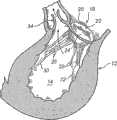
现在参见图1-图2,心脏12的二尖瓣18的机能将被描述.所述二尖瓣18位于心脏的左心房和左心室14之间.二尖瓣18包括环带20和一对小叶22,24,该对小叶选择性地允许和阻止血液流入左心室14.小叶22,24通过腱索或腱26,28从相应乳头肌30,32向上延伸而被支撑以便接合.血液通过二尖瓣18进入左心室14,在心脏12随后的收缩过程中通过主动脉瓣34排出.如图2a所示,小叶22,24被拉开且伸入左心室14中,以便打开二尖瓣18从而允许血液穿过而进入左心室14.如图2b所示,所述小叶22,24相接触以密封二尖瓣18,从而阻止血液从左心室14输送回左心房.Referring now to FIGS. 1-2 , the function of the
该二尖瓣具有前小叶22和后小叶24。小叶22,24在连合36,38接合,并且二尖瓣18在所述连合36,38之间具有开口40。所述前小叶22大于所述后小叶24,因此所述二尖瓣18的开口40具有弓形形状。所述开口40通过小叶22,24的运动而被打开和关闭。所述运动主要是由位于连合36,38之间的小叶22,24的自由边42,44来进行的。The mitral valve has an
在图3中显示了有病的二尖瓣18。小叶22,24不能完全接合,因而二尖瓣18的开口40不能完全关闭。在这种情况下,血液将通过开口40从左心室14往回泄漏到左心房中。这意味着心脏12的机能降低了,因为血液往回流动穿过系统而不是泵出到主动脉。因此,将需要确保小叶22,24能够完全关闭二尖瓣18。A diseased
现在参见图4a-图4b,利用根据本发明的装置治疗有病的二尖瓣18的原理将被描述。图4a显示带有开口40的二尖瓣18,开口40由于小叶22,24不能完全接合而没有被完全关闭。箭头A表示要施加到二尖瓣18上的力,以便重塑二尖瓣18,使得小叶22,24能够完全关闭。如图4a所示,所述二尖瓣通过分别拉所述连合36,38,即小叶22,24之间的接合部位而被重塑。这意味着二尖瓣开口40被拉长,并且小叶22,24的自由边42,44被更靠近地拉到一起。因此,小叶22,24能够关闭二尖瓣18而防止泄漏。Referring now to Figures 4a-4b, the principles of treating a diseased
尽管关于二尖瓣进行了说明,但可以理解,本发明也可应用于任何具有两个小叶的其他瓣膜,或者也可应用于具有三个小叶的瓣膜。Although described in relation to a mitral valve, it will be appreciated that the invention is applicable to any other valve having two leaflets, or also to valves having three leaflets.
现在参见图5a-图5g,根据本发明用于治疗有病的二尖瓣18的装置50的实施例将被描述。该装置要被插入二尖瓣18中,以便与连合36,38相接触。当在装置50和连合36,38之间形成接触时,该装置50将经历形状改变,以便将所述瓣膜组织与该装置带到一起,从而进行如上参见图4所述的二尖瓣18的重塑。Referring now to Figures 5a-5g, an embodiment of a
如图5a-图5g所示,所述装置50包括第一接触点52和第二接触点54,所述接触点分别在连合36,38处与瓣膜组织相接触。该装置50在接触点52,54处可以是钩形的,由此该装置50可在小叶22,24的两侧在连合36,38处形成接触。该装置50在接触点52,54处可进一步包括倒钩或者长钉或者任何尖突起(未示出),所述倒钩或者长钉或者尖突起可穿入所述瓣膜组织,以便将该装置50固定到所述瓣膜组织上。或者,该装置50也可以被布置成通过缝合线或夹子来固定到所述瓣膜组织上。As shown in Figures 5a-5g, the
当植入所述装置50时,整个装置50应该与所述瓣膜组织相接触,以便能使该装置50长到所述瓣膜组织中。这意味着该装置50对于血液流动来说不会呈现异物面,因而可防止血液凝固。为此,如图5a-图5f所示,该装置50可以在接触点52,54之间具有细长部件56。该细长部件56可被布置为沿着所述瓣膜组织整个长度延伸,因而该装置50最终可以完全长入该瓣膜组织中。所述装置50应该在整个心脏动作周期接触该瓣膜组织。由于小叶22,24在心脏动作过程中移动以便打开和关闭二尖瓣18,因此该细长部件56优选被放置为与环带20相接触,或者与接近该环带20的小叶组织相接触。该装置50在接触点52,54处弯曲,以便该细长部件可以在大致垂直于其中有所述钩形延伸的平面的平面内延伸。这意味着该装置50的细长部件56可以沿着所述瓣膜组织在二尖瓣18的环带20所在的平面内延伸,而接触点52,54被布置为与二尖瓣18的连合36,38相接触。或者,该细长部件56可以被固定到该装置50的接触部分上,以便该细长部件56可以在所述环带20所在的平面内延伸。When the
如图5a-图5f所示,该细长部件56可以在接触点52,54之间以多种不同方式延伸。该细长部件56可被放置为在连合36,38之间与所述瓣膜组织相接触。如图2-图4所示,所述二尖瓣18的开口40具有弓形形状。因此,即使该细长部件56基本上沿着直线在连合36,38之间延伸,该细长部件也可以与瓣膜组织相接触。然而,如果该细长部件56具有弓形或者弯曲的形状,则其可被放置为与更接近环带20的瓣膜组织相接触,在心脏动作过程中该组织经历更少的运动。因此,所述细长部件56可以如图5a所示地被弯曲,或弯曲成如图5b和图5f所示的C形,或者弯曲成如图5c和图5e所示的轻微弓形。然而,该细长部件可具有如图5d所示的波状形式,且沿着二尖瓣18的前小叶22延伸。As shown in Figures 5a-5f, the
如图5g所示,可选地,该装置可以是环形,以便主要沿着二尖瓣18的环带20延伸。该环形在连合36,38偏离环带20的形状,以允许所述装置50和连合36,38相接触。Alternatively, the device may be annular so as to extend primarily along the
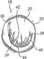
如图6a和图6c所示,所述装置50处于第一形状时被插入二尖瓣18中。该装置50被布置成所述第一形状,以便在该装置50和连合36,38之间形成接触。所述装置50可随后变换为第二形状,以便重塑二尖瓣18,如图6b和图6d所示。所述细长部件56在所述装置50的第一形状和第二形状之间改变形状。该细长部件56的弓形或弯曲程度变小,以便将接触点52,54进一步推开,并因而拉伸二尖瓣18的开口40,使得小叶22,24的自由边42,44被更靠近地拉到一起。As shown in Figures 6a and 6c, the
尽管图6a-图6d所示装置50被放置在二尖瓣18的心房侧,但应该理解,该装置50也可选择放置在二尖瓣18的心室侧。这样,该装置50可放置为与腱26,28相接触,以便该装置50邻接二尖瓣18的心室侧并可长入该瓣膜组织中。Although the
所述装置50可以是弹性的,以便在其变形为第一形状时,该装置具有内在力使其呈现第二形状。这样,该装置50可在外力作用下受到限制以在将该装置50插入心脏瓣膜的连合36,38之间的过程中保持其处于第一形状。对所述装置50的限制可以被布置为弯曲细长部件56或者压缩细长部件56,以便接触点52,54被更靠近地拉到一起。该装置50可以由具有相当刚性的材料制成,以便该装置50的弹性可恢复该装置50的形状,从而在释放对该装置50的限制时重塑该二尖瓣18。然而,所述装置50处于其第二形状时可稍具柔韧性,以允许环带20和连合36,38在心脏动作过程中有小的移动,同时仍然保持连合36,38处于被重塑的形状而被拉伸开。该装置可由任何合适的医学等级的材料制成,例如医学等级的金属或塑料。The
或者,该装置50可由形状记忆材料制成。这样,该装置50可在马氏体状态下被插入二尖瓣18中,其中该装置相对较软而且容易变形。因此,该装置50可在马氏体状态下容易地被插入并接触所述二尖瓣18的连合36,38。当该装置被加热到高于转变温度时,该装置50转变成奥氏体状态并呈现出程序控制的形状。因此,该装置50具有使其呈现第二形状的内在力并且保持所需的形状。该装置可由例如镍钛合金的形状记忆合金,或者形状记忆聚合物制成。Alternatively, the
通常,该装置处于第一形状时所述接触点之间的距离为18~20mm,此距离对应于二尖瓣的连合之间的正常距离。该装置形状的改变通常可以使接触点之间的距离增加40%,以重塑该二尖瓣。Typically, the distance between said contact points when the device is in the first shape is 18-20 mm, which corresponds to the normal distance between the commissures of the mitral valves. Changes in the shape of the device typically increase the distance between contact points by 40% to reshape the mitral valve.
现在将描述利用该装置治疗心脏瓣膜的方法.该装置可通过开放式外科手术被植入心脏内.该装置被带入到二尖瓣18中并放置为与连合36,38相接触.如图7所示,该装置可穿过心脏12的顶点插入二尖瓣18.在插入过程中,该装置50可例如通过压细长部件56以使该细长部件56弯曲的方式或者通过在该细长部件56的不同部分之间延伸的限制线以使这些部分保持彼此间最大距离的方式,被限制为所述第一形状.或者,该装置50也可通过保持其温度在转变温度以下以防止该装置50呈现其第二形状的方式,被保持在其第一形状.A method of treating a heart valve using the device will now be described. The device may be implanted in the heart by open surgery. The device is brought into the
当该装置50已被放置为与所述连合36,38相接触时,该装置50被固定到所述瓣膜组织上。这可通过如下方式来实现:即通过例如将该装置与瓣膜组织缝合或者使用一个或更多的夹子夹在该装置和瓣膜组织上的方式来将该装置50的各部分连接到所述瓣膜组织上。或者,在所述装置50上布置固定装置,该固定装置穿入瓣膜组织以便将该装置50固定到该瓣膜组织上。When the
当所述装置50已经被牢固地固定到所述瓣膜组织上时,该装置50被允许从其第一形状转变为其第二形状。因此,通过例如释放作用在细长部件56上的压力或者切断限制线的方式来释放限制。或者,该装置50可被加热以呈现奥氏体状态,并因此转变为其程序控制的第二形状。当呈现第二形状时,该装置50将重塑所述二尖瓣18,从而使二尖瓣18的开口40具有可由小叶22,24完全关闭的形式。When the
现在参见图8-图9,插入该装置50的基于导管的方法将被描述。该装置50通过导管60插入心脏12中。如图8a所示,所述导管60通过患者腹股沟中的股动脉62或者患者手臂中的锁骨下动脉64而被插入身体中,然后逆行穿过所述动脉被引导进心脏12中,再穿过主动脉瓣34进入左心室14。或者,如图8b所示,所述导管60可通过腔静脉被引导进右心房66,然后可穿过房间隔68而到达左心房70。Referring now to FIGS. 8-9 , a catheter-based method of inserting the
如图9a所示,所述装置50可被布置在导管60中位于承载器72的末端并由限制套74覆盖。当该导管60已经被插入二尖瓣18中时,如图9b所示,所述承载器72可被部分地推出到所述限制套74之外。这样,该装置50的接触点52,54可接触所述连合36,38。然后,所述承载器72可被完全推出到所述限制套74之外,以使该装置50呈现其第二形状并重塑该二尖瓣18。接着,该装置50可从所述承载器72被释放,所述导管60可从身体中抽出,并将该装置50留在二尖瓣18中的适当位置。As shown in FIG. 9 a , the
应该强调的是,此处描述的实施例决不是限制,并且在所附权利要求限定的保护范围内可以有许多替换实施例。It should be emphasized that the embodiments described here are in no way limiting and that many alternative embodiments are possible within the scope of protection defined by the appended claims.
Claims (16)
Translated fromChineseApplications Claiming Priority (6)
| Application Number | Priority Date | Filing Date | Title |
|---|---|---|---|
| SE0403046ASE0403046D0 (en) | 2004-12-15 | 2004-12-15 | A device and method for improving the function of a heart valve |
| SE0403046-6 | 2004-12-15 | ||
| SE04030466 | 2004-12-15 | ||
| US63609604P | 2004-12-16 | 2004-12-16 | |
| US60/636,096 | 2004-12-16 | ||
| PCT/SE2005/001914WO2006065212A1 (en) | 2004-12-15 | 2005-12-14 | A device and method for improving the function of a heart valve |
Related Child Applications (1)
| Application Number | Title | Priority Date | Filing Date |
|---|---|---|---|
| CN201010138346XADivisionCN101978933A (en) | 2004-12-15 | 2005-12-14 | A device and method for improving the function of a heart valve |
Publications (2)
| Publication Number | Publication Date |
|---|---|
| CN101087571A CN101087571A (en) | 2007-12-12 |
| CN101087571Btrue CN101087571B (en) | 2010-05-12 |
Family
ID=33563209
Family Applications (2)
| Application Number | Title | Priority Date | Filing Date |
|---|---|---|---|
| CN201010138346XAPendingCN101978933A (en) | 2004-12-15 | 2005-12-14 | A device and method for improving the function of a heart valve |
| CN2005800429675AExpired - Fee RelatedCN101087571B (en) | 2004-12-15 | 2005-12-14 | device and method for improving heart valve function |
Family Applications Before (1)
| Application Number | Title | Priority Date | Filing Date |
|---|---|---|---|
| CN201010138346XAPendingCN101978933A (en) | 2004-12-15 | 2005-12-14 | A device and method for improving the function of a heart valve |
Country Status (7)
| Country | Link |
|---|---|
| US (3) | US10201424B2 (en) |
| EP (1) | EP1827315A4 (en) |
| JP (1) | JP4980239B2 (en) |
| CN (2) | CN101978933A (en) |
| CA (1) | CA2590199C (en) |
| SE (1) | SE0403046D0 (en) |
| WO (1) | WO2006065212A1 (en) |
Families Citing this family (60)
| Publication number | Priority date | Publication date | Assignee | Title |
|---|---|---|---|---|
| US6440164B1 (en) | 1999-10-21 | 2002-08-27 | Scimed Life Systems, Inc. | Implantable prosthetic valve |
| AU2003285943B2 (en) | 2002-10-24 | 2008-08-21 | Boston Scientific Limited | Venous valve apparatus and method |
| US6945957B2 (en) | 2002-12-30 | 2005-09-20 | Scimed Life Systems, Inc. | Valve treatment catheter and methods |
| US7854761B2 (en) | 2003-12-19 | 2010-12-21 | Boston Scientific Scimed, Inc. | Methods for venous valve replacement with a catheter |
| US8128681B2 (en) | 2003-12-19 | 2012-03-06 | Boston Scientific Scimed, Inc. | Venous valve apparatus, system, and method |
| US7566343B2 (en) | 2004-09-02 | 2009-07-28 | Boston Scientific Scimed, Inc. | Cardiac valve, system, and method |
| US20060173490A1 (en) | 2005-02-01 | 2006-08-03 | Boston Scientific Scimed, Inc. | Filter system and method |
| US7867274B2 (en) | 2005-02-23 | 2011-01-11 | Boston Scientific Scimed, Inc. | Valve apparatus, system and method |
| US8608797B2 (en)* | 2005-03-17 | 2013-12-17 | Valtech Cardio Ltd. | Mitral valve treatment techniques |
| US7722666B2 (en) | 2005-04-15 | 2010-05-25 | Boston Scientific Scimed, Inc. | Valve apparatus, system and method |
| US8012198B2 (en) | 2005-06-10 | 2011-09-06 | Boston Scientific Scimed, Inc. | Venous valve, system, and method |
| US8128691B2 (en) | 2005-09-07 | 2012-03-06 | Medtentia International Ltd. Oy | Device and method for improving the function of a heart valve |
| US7569071B2 (en) | 2005-09-21 | 2009-08-04 | Boston Scientific Scimed, Inc. | Venous valve, system, and method with sinus pocket |
| WO2008091493A1 (en) | 2007-01-08 | 2008-07-31 | California Institute Of Technology | In-situ formation of a valve |
| US7967853B2 (en) | 2007-02-05 | 2011-06-28 | Boston Scientific Scimed, Inc. | Percutaneous valve, system and method |
| US7892276B2 (en) | 2007-12-21 | 2011-02-22 | Boston Scientific Scimed, Inc. | Valve with delayed leaflet deployment |
| US20100121437A1 (en) | 2008-04-16 | 2010-05-13 | Cardiovascular Technologies, Llc | Transvalvular intraannular band and chordae cutting for ischemic and dilated cardiomyopathy |
| US11083579B2 (en) | 2008-04-16 | 2021-08-10 | Heart Repair Technologies, Inc. | Transvalvular intraanular band and chordae cutting for ischemic and dilated cardiomyopathy |
| US8262725B2 (en)* | 2008-04-16 | 2012-09-11 | Cardiovascular Technologies, Llc | Transvalvular intraannular band for valve repair |
| US10456259B2 (en) | 2008-04-16 | 2019-10-29 | Heart Repair Technologies, Inc. | Transvalvular intraannular band for mitral valve repair |
| US20100121435A1 (en) | 2008-04-16 | 2010-05-13 | Cardiovascular Technologies, Llc | Percutaneous transvalvular intrannular band for mitral valve repair |
| US20100131057A1 (en) | 2008-04-16 | 2010-05-27 | Cardiovascular Technologies, Llc | Transvalvular intraannular band for aortic valve repair |
| US11013599B2 (en) | 2008-04-16 | 2021-05-25 | Heart Repair Technologies, Inc. | Percutaneous transvalvular intraannular band for mitral valve repair |
| US20120179184A1 (en)* | 2009-09-15 | 2012-07-12 | Boris Orlov | Heart valve remodeling |
| WO2011047168A1 (en)* | 2009-10-14 | 2011-04-21 | Cardiovascular Technologies, Llc | Percutaneous transvalvular intraannular band for mitral valve repair |
| US8870950B2 (en) | 2009-12-08 | 2014-10-28 | Mitral Tech Ltd. | Rotation-based anchoring of an implant |
| US8657872B2 (en) | 2010-07-19 | 2014-02-25 | Jacques Seguin | Cardiac valve repair system and methods of use |
| US11653910B2 (en) | 2010-07-21 | 2023-05-23 | Cardiovalve Ltd. | Helical anchor implantation |
| DK4233795T3 (en)* | 2010-10-05 | 2024-08-26 | Edwards Lifesciences Corp | Prosthetic heart valve |
| US8845717B2 (en) | 2011-01-28 | 2014-09-30 | Middle Park Medical, Inc. | Coaptation enhancement implant, system, and method |
| US8888843B2 (en) | 2011-01-28 | 2014-11-18 | Middle Peak Medical, Inc. | Device, system, and method for transcatheter treatment of valve regurgitation |
| US9668859B2 (en) | 2011-08-05 | 2017-06-06 | California Institute Of Technology | Percutaneous heart valve delivery systems |
| US20150351906A1 (en) | 2013-01-24 | 2015-12-10 | Mitraltech Ltd. | Ventricularly-anchored prosthetic valves |
| CA2898984C (en)* | 2013-01-25 | 2021-03-16 | Medtentia International Ltd Oy | A medical device and method for facilitating selection of an annuloplasty implant |
| EP2948100B1 (en)* | 2013-01-25 | 2021-05-05 | Medtentia International Ltd Oy | A system for cardiac valve repair |
| WO2014144247A1 (en) | 2013-03-15 | 2014-09-18 | Arash Kheradvar | Handle mechanism and functionality for repositioning and retrieval of transcatheter heart valves |
| US10166098B2 (en) | 2013-10-25 | 2019-01-01 | Middle Peak Medical, Inc. | Systems and methods for transcatheter treatment of valve regurgitation |
| EP3157469B2 (en) | 2014-06-18 | 2024-10-02 | Polares Medical Inc. | Mitral valve implants for the treatment of valvular regurgitation |
| CA2958065C (en) | 2014-06-24 | 2023-10-31 | Middle Peak Medical, Inc. | Systems and methods for anchoring an implant |
| EP3174502B1 (en) | 2014-07-30 | 2022-04-06 | Cardiovalve Ltd | Apparatus for implantation of an articulatable prosthetic valve |
| CN110141399B (en) | 2015-02-05 | 2021-07-27 | 卡迪尔维尔福股份有限公司 | Prosthetic valve with axial sliding frame |
| CN108348334A (en)* | 2015-10-27 | 2018-07-31 | 谢尔蒂斯有限公司 | Medical devices using bioabsorbable materials |
| US9592121B1 (en) | 2015-11-06 | 2017-03-14 | Middle Peak Medical, Inc. | Device, system, and method for transcatheter treatment of valvular regurgitation |
| US10531866B2 (en) | 2016-02-16 | 2020-01-14 | Cardiovalve Ltd. | Techniques for providing a replacement valve and transseptal communication |
| US20190231525A1 (en) | 2016-08-01 | 2019-08-01 | Mitraltech Ltd. | Minimally-invasive delivery systems |
| CA3031187A1 (en) | 2016-08-10 | 2018-02-15 | Cardiovalve Ltd. | Prosthetic valve with concentric frames |
| AU2017382273A1 (en) | 2016-12-22 | 2019-08-08 | Heart Repair Technologies, Inc. | Percutaneous delivery systems for anchoring an implant in a cardiac valve annulus |
| US10653524B2 (en) | 2017-03-13 | 2020-05-19 | Polares Medical Inc. | Device, system, and method for transcatheter treatment of valvular regurgitation |
| US10478303B2 (en) | 2017-03-13 | 2019-11-19 | Polares Medical Inc. | Device, system, and method for transcatheter treatment of valvular regurgitation |
| JP7159230B2 (en) | 2017-03-13 | 2022-10-24 | ポラレス・メディカル・インコーポレイテッド | Devices, systems and methods for transcatheter treatment of valvular regurgitation |
| US12064347B2 (en) | 2017-08-03 | 2024-08-20 | Cardiovalve Ltd. | Prosthetic heart valve |
| US11793633B2 (en) | 2017-08-03 | 2023-10-24 | Cardiovalve Ltd. | Prosthetic heart valve |
| WO2019097510A1 (en)* | 2017-11-15 | 2019-05-23 | Tel Hashomer Medical Research, Infrastructure And Services Ltd. | Mitral brace |
| WO2019226803A1 (en) | 2018-05-22 | 2019-11-28 | Boston Scientific Scimed, Inc. | Percutaneous papillary muscle relocation |
| WO2020167672A1 (en) | 2019-02-11 | 2020-08-20 | Subramanian Valavanur A | Percutaneous delivery systems for anchoring an implant in a cardiac valve annulus |
| EP3962417A4 (en) | 2019-05-02 | 2023-01-18 | University of Maryland, Baltimore | VALVE TRANSLOCATION DEVICE AND METHODS FOR TREATMENT OF FUNCTIONAL VALVE REGURGITATION |
| WO2021005246A1 (en)* | 2019-07-11 | 2021-01-14 | Medtentia International Ltd Oy | Annuloplasty device |
| US12357459B2 (en) | 2020-12-03 | 2025-07-15 | Cardiovalve Ltd. | Transluminal delivery system |
| US11464634B2 (en) | 2020-12-16 | 2022-10-11 | Polares Medical Inc. | Device, system, and method for transcatheter treatment of valvular regurgitation with secondary anchors |
| US11759321B2 (en) | 2021-06-25 | 2023-09-19 | Polares Medical Inc. | Device, system, and method for transcatheter treatment of valvular regurgitation |
Citations (3)
| Publication number | Priority date | Publication date | Assignee | Title |
|---|---|---|---|---|
| US6391054B2 (en)* | 1994-07-29 | 2002-05-21 | Edwards Lifesciences Corporation | Expandable annuloplasty ring |
| CN1391453A (en)* | 1999-09-17 | 2003-01-15 | 卡迪亚克·康赛普茨公司 | Mitral valve annuloplasty ring and method |
| US6602289B1 (en)* | 1999-06-08 | 2003-08-05 | S&A Rings, Llc | Annuloplasty rings of particular use in surgery for the mitral valve |
Family Cites Families (13)
| Publication number | Priority date | Publication date | Assignee | Title |
|---|---|---|---|---|
| JPH05184611A (en)* | 1991-03-19 | 1993-07-27 | Kenji Kusuhara | Valvular annulation retaining member and its attaching method |
| EP0996393B1 (en)* | 1997-07-22 | 2005-05-18 | Edwards Lifesciences Corporation | Expandable annuloplasty ring |
| SE514718C2 (en)* | 1999-06-29 | 2001-04-09 | Jan Otto Solem | Apparatus for treating defective closure of the mitral valve apparatus |
| MXPA02011590A (en)* | 2000-05-25 | 2004-07-30 | Bioring S A | Device for shrinking or reinforcing the heart valvular orifices. |
| US6419696B1 (en)* | 2000-07-06 | 2002-07-16 | Paul A. Spence | Annuloplasty devices and related heart valve repair methods |
| US8784482B2 (en)* | 2000-09-20 | 2014-07-22 | Mvrx, Inc. | Method of reshaping a heart valve annulus using an intravascular device |
| US6723038B1 (en) | 2000-10-06 | 2004-04-20 | Myocor, Inc. | Methods and devices for improving mitral valve function |
| AU2002362442B2 (en)* | 2001-10-01 | 2008-08-07 | Ample Medical, Inc. | Methods and devices for heart valve treatments |
| EP1465555B1 (en)* | 2001-12-21 | 2015-05-06 | QuickRing Medical Technologies Ltd. | Implantation system for annuloplasty rings |
| US6797001B2 (en)* | 2002-03-11 | 2004-09-28 | Cardiac Dimensions, Inc. | Device, assembly and method for mitral valve repair |
| AU2003277118A1 (en) | 2002-10-01 | 2004-04-23 | Ample Medical, Inc. | Devices for retaining native heart valve leaflet |
| CN100553590C (en)* | 2002-10-01 | 2009-10-28 | 安普尔医药公司 | The device of finishing semilunar valve annulus |
| US20040220593A1 (en)* | 2003-05-01 | 2004-11-04 | Secant Medical, Llc | Restraining clip for mitral valve repair |
- 2004
- 2004-12-15SESE0403046Apatent/SE0403046D0/enunknown
- 2005
- 2005-12-14CACA2590199Apatent/CA2590199C/ennot_activeExpired - Fee Related
- 2005-12-14EPEP05819067.9Apatent/EP1827315A4/ennot_activeCeased
- 2005-12-14WOPCT/SE2005/001914patent/WO2006065212A1/enactiveApplication Filing
- 2005-12-14JPJP2007546607Apatent/JP4980239B2/ennot_activeExpired - Fee Related
- 2005-12-14USUS11/793,028patent/US10201424B2/ennot_activeExpired - Fee Related
- 2005-12-14CNCN201010138346XApatent/CN101978933A/enactivePending
- 2005-12-14CNCN2005800429675Apatent/CN101087571B/ennot_activeExpired - Fee Related
- 2019
- 2019-01-11USUS16/246,374patent/US10765516B2/ennot_activeExpired - Fee Related
- 2020
- 2020-09-06USUS17/013,613patent/US20200397580A1/ennot_activeAbandoned
Patent Citations (3)
| Publication number | Priority date | Publication date | Assignee | Title |
|---|---|---|---|---|
| US6391054B2 (en)* | 1994-07-29 | 2002-05-21 | Edwards Lifesciences Corporation | Expandable annuloplasty ring |
| US6602289B1 (en)* | 1999-06-08 | 2003-08-05 | S&A Rings, Llc | Annuloplasty rings of particular use in surgery for the mitral valve |
| CN1391453A (en)* | 1999-09-17 | 2003-01-15 | 卡迪亚克·康赛普茨公司 | Mitral valve annuloplasty ring and method |
Also Published As
| Publication number | Publication date |
|---|---|
| EP1827315A4 (en) | 2017-05-31 |
| CA2590199A1 (en) | 2006-06-22 |
| JP4980239B2 (en) | 2012-07-18 |
| US20080109075A1 (en) | 2008-05-08 |
| US20200397580A1 (en) | 2020-12-24 |
| US10765516B2 (en) | 2020-09-08 |
| EP1827315A1 (en) | 2007-09-05 |
| SE0403046D0 (en) | 2004-12-15 |
| JP2008523886A (en) | 2008-07-10 |
| US20190183646A1 (en) | 2019-06-20 |
| CN101978933A (en) | 2011-02-23 |
| CN101087571A (en) | 2007-12-12 |
| CA2590199C (en) | 2014-01-21 |
| WO2006065212A1 (en) | 2006-06-22 |
| US10201424B2 (en) | 2019-02-12 |
Similar Documents
| Publication | Publication Date | Title |
|---|---|---|
| CN101087571B (en) | device and method for improving heart valve function | |
| US20220117733A1 (en) | Device And Method For Improving The Function Of A Heart Valve | |
| EP2649964B1 (en) | Devices for improving the function of a heart valve | |
| US20230255771A1 (en) | Annuloplasty device | |
| EP4465924A1 (en) | Annuloplasty device |
Legal Events
| Date | Code | Title | Description |
|---|---|---|---|
| C06 | Publication | ||
| PB01 | Publication | ||
| C10 | Entry into substantive examination | ||
| SE01 | Entry into force of request for substantive examination | ||
| ASS | Succession or assignment of patent right | Owner name:MEIDETANTIYA INTERNATIONAL CO., LTD. Free format text:FORMER OWNER: MEIDETANTIYA CO.,LTD. Effective date:20100325 | |
| C41 | Transfer of patent application or patent right or utility model | ||
| COR | Change of bibliographic data | Free format text:CORRECT: ADDRESS; FROM: LOND, SWEDEN TO: HELSINKI, FINLAND | |
| TA01 | Transfer of patent application right | Effective date of registration:20100325 Address after:Helsinki Applicant after:Medtentia AB Address before:Swedish wave Applicant before:Medtentia AB | |
| C14 | Grant of patent or utility model | ||
| GR01 | Patent grant | ||
| CF01 | Termination of patent right due to non-payment of annual fee | Granted publication date:20100512 Termination date:20191214 | |
| CF01 | Termination of patent right due to non-payment of annual fee |