CN101087564B - Ligation device - Google Patents
Ligation deviceDownload PDFInfo
- Publication number
- CN101087564B CN101087564BCN2005800444317ACN200580044431ACN101087564BCN 101087564 BCN101087564 BCN 101087564BCN 2005800444317 ACN2005800444317 ACN 2005800444317ACN 200580044431 ACN200580044431 ACN 200580044431ACN 101087564 BCN101087564 BCN 101087564B
- Authority
- CN
- China
- Prior art keywords
- sheath
- pressing member
- relative
- diameter
- ligation device
- Prior art date
- Legal status (The legal status is an assumption and is not a legal conclusion. Google has not performed a legal analysis and makes no representation as to the accuracy of the status listed.)
- Active
Links
Images


Classifications
- A—HUMAN NECESSITIES
- A61—MEDICAL OR VETERINARY SCIENCE; HYGIENE
- A61B—DIAGNOSIS; SURGERY; IDENTIFICATION
- A61B17/00—Surgical instruments, devices or methods
- A61B17/12—Surgical instruments, devices or methods for ligaturing or otherwise compressing tubular parts of the body, e.g. blood vessels or umbilical cord
- A61B17/122—Clamps or clips, e.g. for the umbilical cord
- A61B17/1227—Spring clips
- A—HUMAN NECESSITIES
- A61—MEDICAL OR VETERINARY SCIENCE; HYGIENE
- A61B—DIAGNOSIS; SURGERY; IDENTIFICATION
- A61B17/00—Surgical instruments, devices or methods
- A61B17/12—Surgical instruments, devices or methods for ligaturing or otherwise compressing tubular parts of the body, e.g. blood vessels or umbilical cord
- A61B17/128—Surgical instruments, devices or methods for ligaturing or otherwise compressing tubular parts of the body, e.g. blood vessels or umbilical cord for applying or removing clamps or clips
- A61B17/1285—Surgical instruments, devices or methods for ligaturing or otherwise compressing tubular parts of the body, e.g. blood vessels or umbilical cord for applying or removing clamps or clips for minimally invasive surgery
- A—HUMAN NECESSITIES
- A61—MEDICAL OR VETERINARY SCIENCE; HYGIENE
- A61B—DIAGNOSIS; SURGERY; IDENTIFICATION
- A61B90/00—Instruments, implements or accessories specially adapted for surgery or diagnosis and not covered by any of the groups A61B1/00 - A61B50/00, e.g. for luxation treatment or for protecting wound edges
- A61B90/03—Automatic limiting or abutting means, e.g. for safety
- A61B2090/037—Automatic limiting or abutting means, e.g. for safety with a frangible part, e.g. by reduced diameter
Landscapes
- Health & Medical Sciences (AREA)
- Surgery (AREA)
- Life Sciences & Earth Sciences (AREA)
- Heart & Thoracic Surgery (AREA)
- Nuclear Medicine, Radiotherapy & Molecular Imaging (AREA)
- Vascular Medicine (AREA)
- Engineering & Computer Science (AREA)
- Biomedical Technology (AREA)
- Reproductive Health (AREA)
- Medical Informatics (AREA)
- Molecular Biology (AREA)
- Animal Behavior & Ethology (AREA)
- General Health & Medical Sciences (AREA)
- Public Health (AREA)
- Veterinary Medicine (AREA)
- Surgical Instruments (AREA)
Abstract
Description
Translated fromChinese技术领域technical field
本发明涉及一种通过夹子(clip)对活体组织进行结扎的结扎装置。The invention relates to a ligating device for ligating living tissues through clips.
背景技术Background technique
以往,使用如下的结扎装置,即,与内窥镜组合起来使用,通过夹子对体腔内的活体组织进行结扎。Conventionally, a ligation device is used in combination with an endoscope to ligate living tissue in a body cavity with a clip.
在日本特开2004-121485号公报的结扎装置中,夹子具有受到扩开的力的一对臂。此外,将按压管包嵌在夹子上以使一对臂闭合来把持活体组织,并利用按压管将一对臂保持在闭合状态,由此对活体组织进行结扎。In the ligation device disclosed in Japanese Patent Laid-Open No. 2004-121485, the clip has a pair of arms that receive a force of expansion. In addition, the pressing tube is embedded in the clip to close the pair of arms to hold the living tissue, and the pressing tube is used to keep the pair of arms in the closed state, whereby the living tissue is ligated.
另外,在国际公开第03/030746A1号小册子(pamphlet)的结扎装置中,在盘管护套(coil sheath)的前端部连接有夹子,该夹子具有可开闭的一对夹子脚部。此外,将夹子脚部的基端部拉进盘管护套中,使夹子脚部闭合来把持活体组织,将夹子脚部保持在闭合状态,由此对活体组织进行结扎。In addition, in the ligation device of International Publication No. 03/030746A1 pamphlet, a clip is connected to the front end of a coil sheath, and the clip has a pair of clip legs that can be opened and closed. In addition, the base end of the clip leg is drawn into the coil sheath, the clip leg is closed to hold the living tissue, and the clip leg is kept in the closed state, thereby ligating the living tissue.
在日本特开2004-121485号公报的结扎装置中,一旦将按压管包嵌在夹子上时,就不能再次打开一对臂,从而不能重新把持活体组织。因而,日本特开2004-121485号公报的结扎装置存在不能适当地对活体组织进行结扎的可能性。In the ligation device disclosed in Japanese Patent Laid-Open No. 2004-121485, once the pressing tube is embedded in the clip, the pair of arms cannot be opened again, so that the living tissue cannot be grasped again. Therefore, the ligation device of JP-A-2004-121485 may not be able to properly ligate living tissue.
在这里,在结扎装置中,通常为了可靠地把持活体组织,在夹子上形成锐利的爪部。在国际公开第03/030746A1号小册子的结扎装置中,无法将夹子收纳在盘管护套中,夹子的爪部从盘管护套露出。因而,在将结扎装置贯穿到内窥镜等的通道中的情况下,存在爪部损伤通道内壁,或者爪部挂在通道内壁上而使所需的插入力量增大的可能性。因而,国际公开第03/030746A1号小册子的结扎装置不适于插入体腔内。Here, in the ligation device, sharp claws are generally formed on the clips in order to securely grasp the living tissue. In the ligation device of International Publication No. 03/030746A1, the clip cannot be accommodated in the coil sheath, and the claws of the clip are exposed from the coil sheath. Therefore, when the ligature device is inserted into a channel of an endoscope or the like, the inner wall of the channel may be damaged by the claw, or the claw may be caught on the inner wall of the channel, thereby increasing the required insertion force. Therefore, the ligation device of International Publication No. 03/030746A1 pamphlet is not suitable for insertion into a body cavity.
发明内容Contents of the invention
本发明就是着眼于上述课题而完成的,其目的是提供一种最适于体腔内的活体组织的结扎的结扎装置。The present invention has been made with the above problems in mind, and an object of the present invention is to provide a ligation device most suitable for ligation of living tissue in a body cavity.
本发明的一实施方式的结扎装置的特征在于,具备:夹子,该夹子具有对活体组织进行结扎并可开闭的夹子爪部件以及按压部件,所述夹子爪部件可进退地内装在该按压部件中,所述夹子爪部件相对于所述按压部件进退并通过与所述按压部件的相互作用而开闭;护套,其将所述夹子以能够进退且所述夹子爪部件不会露出到外部的方式收纳起来;操作线,其可进退地贯穿到所述护套中,该操作线的前端部与所述夹子爪部件连接,该操作线能够使所述夹子相对于所述护套进退;进退限制机构,为了能够通过所述夹子对活体组织进行结扎,该进退限制机构限制所述按压部件在所述护套的前端部相对于所述护套的进退,能够通过所述操作线相对于所述护套的进退,使所述夹子爪部件相对于所述按压部件进退;以及释放机构,其在对所述活体组织进行结扎的状态下,使所述夹子的至少一部分从所述护套释放。A ligation device according to an embodiment of the present invention is characterized in that it includes a clip including a clip claw member that ligates living tissue and can be opened and closed, and a pressing member, and the clip claw member is built in the pressing member so that it can advance and retreat. Among them, the clip claw part advances and retreats relative to the pressing part and is opened and closed by interacting with the pressing part; the sheath, which enables the clip to advance and retreat without the clip claw part being exposed to the outside The operation wire can be inserted into the sheath in a forward and backward manner, and the front end of the operation wire is connected to the clip claw part, and the operation wire can make the clip advance and retreat relative to the sheath; The advancing and retreating restricting mechanism, in order to ligate the living tissue through the clip, restricts the advancing and retreating of the pressing member relative to the sheath at the front end of the sheath, and can be moved relative to the sheath through the operating wire. advance and retreat of the sheath, the clip claw member advances and retreats relative to the pressing member; and a release mechanism, which releases at least a part of the clip from the sheath in a state where the living tissue is ligated. freed.
本发明优选的一实施方式的结扎装置的特征在于,所述进退限制机构具有:限制所述按压部件相对于所述护套的后退的后退限制机构;以及限制所述按压部件相对于所述护套的前进的前进限制机构。The ligation device according to a preferred embodiment of the present invention is characterized in that the advance and retreat restricting mechanism has: a retraction restricting mechanism that restricts the retraction of the pressing member relative to the sheath; Set of advancing forward limiting mechanisms.
本发明优选的一实施方式的结扎装置的特征在于,所述后退限制机构具有:设置在所述按压部件中的后退限制抵接部;以及设置在所述护套中,与配置在前端侧的所述后退限制抵接部抵接,限制所述按压部件的后退的后退限制止挡。According to a preferred embodiment of the present invention, the ligation device is characterized in that the retreat restriction mechanism has: a retreat restriction abutting portion provided in the pressing member; The retreat restricting abutting portion abuts against a retreat restricting stopper that restricts retreat of the pressing member.
本发明优选的一实施方式的结扎装置的特征在于,所述按压部件可从所述护套的前端部突出和没入,所述后退限制抵接部具有翼部,该翼部弹性地且可扩开和缩闭地设置在所述按压部件中,并且在所述按压部件被收纳于所述护套中的情况下缩闭,在所述按压部件从所述护套突出的状态下扩开,所述后退限制止挡设置在所述护套的前端,与扩开后的所述翼部抵接,从而限制所述按压部件没入所述护套的前端部。The ligation device according to a preferred embodiment of the present invention is characterized in that the pressing member can protrude and sink from the front end of the sheath, and the retreat restricting abutting portion has wings that are elastically and expandable. is provided in the pressing member so as to be opened and closed, and is contracted when the pressing member is accommodated in the sheath, and expanded when the pressing member protrudes from the sheath, The retreat limiting stopper is arranged at the front end of the sheath, abuts against the expanded wings, thereby restricting the pressing member from sinking into the front end of the sheath.
本发明优选的一实施方式的结扎装置的特征在于,所述按压部件及所述护套为大致筒形状,所述后退限制抵接部通过在所述按压部件中外径增大的后退限制大径部形成,所述后退限制止挡通过在所述护套中内径减小的后退限制护套小径部形成。According to a preferred embodiment of the present invention, the ligation device is characterized in that the pressing member and the sheath are substantially cylindrical in shape, and the retreat restricting abutting portion has a large diameter that is restricted by retreat by increasing the outer diameter of the pressing member. The retraction limiting stop is formed by a small diameter portion of the retraction limiting sheath having a reduced inner diameter in the sheath.
本发明优选的一实施方式的结扎装置的特征在于,通过使所述操作线相对于所述护套进退,使所述夹子相对于所述护套在所述后退限制大径部不与所述后退限制护套小径部抵接的范围内进退,使所述夹子爪部件通过与所述护套的相互作用而开闭,从而可对活体组织进行临时结扎,在所述后退限制大径部与所述后退限制护套小径部抵接的状态下,通过使所述操作线相对于所述护套后退,使所述夹子爪部件相对于所述按压部件后退,从而可对活体组织进行正式结扎。The ligation device according to a preferred embodiment of the present invention is characterized in that, by advancing and retreating the operation wire relative to the sheath, the large diameter portion of the clip relative to the sheath is not in contact with the retraction limiting large diameter portion. The retraction limit sheath advances and retreats within the range where the small-diameter portion of the sheath abuts, so that the clip claw parts can be opened and closed through the interaction with the sheath, so that the living tissue can be temporarily ligated. In a state where the small-diameter portion of the retreat-limiting sheath is in contact, the operating wire is retracted relative to the sheath, and the clip claw member is retracted relative to the pressing member, whereby the main ligation of living tissue can be performed. .
本发明优选的一实施方式的结扎装置的特征在于,在对活体组织进行了正式结扎的情况下,所述夹子爪部件借助于摩擦力而相对于所述按压部件固定。In the ligation device according to a preferred embodiment of the present invention, when the living tissue is completely ligated, the clip claw member is fixed relative to the pressing member by frictional force.
本发明优选的一实施方式的结扎装置的特征在于,所述前进限制机构具有:设置在所述按压部件中的前进限制抵接部;以及设置在所述护套中,与配置在后端侧的所述前进限制抵接部抵接,限制所述按压部件的前进的前进限制止挡。A ligation device according to a preferred embodiment of the present invention is characterized in that the advancement restricting mechanism has: an advancement restricting contact portion provided in the pressing member; The forward limiting abutting portion abuts against the forward limiting stopper that limits the forward movement of the pressing member.
本发明优选的一实施方式的结扎装置的特征在于,所述按压部件及所述护套为大致筒形状,所述前进限制抵接部通过在所述按压部件中外径增大的前进限制大径部形成,所述前进限制止挡通过在所述护套中内径减小的前进限制护套小径部形成。According to a preferred embodiment of the present invention, the ligation device is characterized in that the pressing member and the sheath are substantially cylindrical in shape, and the advance restricting abutting portion has a large advance restricting diameter with an enlarged outer diameter in the pressing member. The advancement limiting stop is formed by a small diameter portion of the advancement limiting sheath having a reduced inner diameter in the sheath.
本发明优选的一实施方式的结扎装置的特征在于,所述前进限制机构具有:设置在所述按压部件中的前进限制抵接部;以及设置在所述护套中,与所述前进限制抵接部抵接,限制所述按压部件的前进的前进限制止挡,在所述按压部件相对于所述护套前进、并且所述前进限制抵接部与所述前进限制止挡抵接的时候,所述翼部扩开。A ligation device according to a preferred embodiment of the present invention is characterized in that the advancement limiting mechanism has: an advancement limiting abutting portion provided in the pressing member; a contact part abuts against an advancement limiting stopper that restricts the advancement of the pressing member, when the pressing member advances relative to the sheath and the advancing limiting abutment part abuts against the advancing limiting stopper , the wings expand.
本发明优选的一实施方式的结扎装置的特征在于,该结扎装置还具备将所述操作线的前端部与所述夹子爪部件相互连接起来的连接部件,所述释放机构具有:第1断裂部,其设置在所述连接部件中,可断裂从而使所述夹子爪部件从所述操作线的前端部分离;以及第2断裂部,其在所述按压部件中设置在所述前进限制抵接部的前端侧,可断裂从而使所述按压部件的前端侧从所述护套分离。A ligation device according to a preferred embodiment of the present invention is characterized in that the ligation device further includes a connection member connecting the distal end portion of the operation wire and the clip claw member to each other, and the release mechanism has: a first breaking portion , which is provided in the connecting member, and is breakable so that the clip claw member is separated from the front end portion of the operation wire; and a second breaking portion, which is provided in the pressing member at the advance limiting abutment The front end side of the part is breakable so that the front end side of the pressing member is separated from the sheath.
本发明优选的一实施方式的结扎装置的特征在于,所述第2断裂部具有强度比所述按压部件的其他部分弱的脆弱部。In the ligation device according to a preferred embodiment of the present invention, the second breaking portion has a weak portion weaker than other portions of the pressing member.
本发明优选的一实施方式的结扎装置的特征在于,关于与所述按压部件的前后方向正交的截面,所述脆弱部的截面积小于所述按压部件的其他部分的截面积。A ligation device according to a preferred embodiment of the present invention is characterized in that the cross-sectional area of the fragile portion is smaller than the cross-sectional area of other portions of the pressing member in a cross section perpendicular to the front-rear direction of the pressing member.
本发明优选的一实施方式的结扎装置的特征在于,所述释放机构具有:卡定部,其在所述连接部件中设置在所述第1断裂部的后端侧;以及卡定支撑部,其在所述按压部件中设置在所述第2断裂部的后端侧,通过使所述操作线相对于所述护套后退,从而所述第1断裂部断裂,所述连接部件后退,所述卡定部卡定于所述卡定支撑部,对所述卡定支撑部朝向后端侧施力,从而所述第2断裂部断裂。The ligation device according to a preferred embodiment of the present invention is characterized in that the release mechanism has: a locking part provided on the rear end side of the first breaking part in the connecting member; and a locking support part, It is provided on the rear end side of the second breaking portion in the pressing member, and when the operation wire is moved back relative to the sheath, the first breaking portion is broken, and the connecting member moves back, so that The locking portion is locked to the locking support portion, and the locking support portion is urged toward the rear end side, whereby the second breaking portion breaks.
本发明优选的一实施方式的结扎装置的特征在于,所述按压部件为大致筒形状,所述连接部件为大致圆柱形状,所述卡定部通过在所述连接部件中外径增大的卡定大径部形成,所述卡定支撑部通过在所述按压部件中内径减小的卡定小径部形成。According to a preferred embodiment of the present invention, the ligation device is characterized in that the pressing member has a substantially cylindrical shape, the connecting member has a substantially cylindrical shape, and the locking portion is locked by an enlarged outer diameter of the connecting member. A large-diameter portion is formed, and the locking support portion is formed by a locking small-diameter portion having a reduced inner diameter in the pressing member.
本发明优选的一实施方式的结扎装置的特征在于,该结扎装置还具备将所述操作线的前端部与所述夹子爪部件相互连接起来的连接部件,所述前进限制机构具有:施力部,其设置在所述操作线的前端部;以及扩缩径部,其弹性地且可扩径和缩径地设置在所述按压部件中,被所述施力部朝向所述按压部件的径向外侧施力,从而扩径形成所述前进限制大径部,所述释放机构具有:第1断裂部,其设置在所述连接部件中,可断裂从而使所述夹子爪部件从所述操作线的前端部分离;所述施力部;以及所述扩缩径部,通过使所述操作线相对于所述护套后退,从而所述第1断裂部断裂,所述施力部后退到比所述扩缩径部更靠后端侧,所述扩缩径部缩径,所述按压部件可向前端侧通过所述前进限制护套小径部。A ligation device according to a preferred embodiment of the present invention is characterized in that the ligation device further includes a connecting member that connects the distal end portion of the operation wire and the clip claw member to each other, and the advance restricting mechanism includes: a biasing portion , which is provided at the front end portion of the operation wire; and a diameter-expanding portion, which is elastically provided in the pressing member so as to be expandable and shrinkable in diameter, and is directed toward the diameter of the pressing member by the biasing portion. Applying force to the outside, so as to expand the diameter to form the large-diameter portion for limiting the advancement, the release mechanism has: a first breaking portion, which is arranged in the connecting part, and can be broken so that the clip claw part can be removed from the operation The front end portion of the wire is separated; the urging portion; and the diameter-expanding portion are retracted by the operation wire relative to the sheath, so that the first breaking portion is broken, and the urging portion is retracted to The diameter of the expanding and contracting portion is reduced on the rear end side of the expanding and contracting diameter portion, and the pressing member can pass through the small diameter portion of the advancement restricting sheath toward the front end side.
本发明优选的一实施方式的结扎装置的特征在于,所述扩缩径部具有凸起部,该凸起部朝向所述按压部件的径向内侧突出,并被所述施力部朝向所述按压部件的径向外侧施力。The ligation device according to a preferred embodiment of the present invention is characterized in that the expanding and contracting diameter portion has a protruding portion that protrudes toward the radially inner side of the pressing member and is directed toward the Press the radially outer side of the part to apply force.
本发明优选的一实施方式的结扎装置的特征在于,上述按压部件具有使上述夹子爪部件相对于上述按压部件前进的弹性部。A ligation device according to a preferred embodiment of the present invention is characterized in that the pressing member has an elastic portion that advances the clip claw member relative to the pressing member.
本发明优选的一实施方式的结扎装置的特征在于,通过使所述操作线相对于所述护套后退、使所述夹子爪部件相对于所述按压部件后退,从而所述弹性部产生弹性变形,当释放所述操作线时,所述弹性部借助于回弹力使所述夹子爪部件相对于所述按压部件前进。The ligation device according to a preferred embodiment of the present invention is characterized in that the elastic portion is elastically deformed by retreating the operation wire relative to the sheath and retreating the clip claw member relative to the pressing member. , when the operation wire is released, the elastic portion advances the clip claw member relative to the pressing member by means of a resilient force.
本发明优选的一实施方式的结扎装置的特征在于,所述按压部件具有桥接部,该桥接部在所述夹子爪部件相对于所述按压部件前进的情况下,强制地打开所述夹子爪部件。The ligation device according to a preferred embodiment of the present invention is characterized in that the pressing member has a bridge portion for forcibly opening the clip claw member when the clip claw member advances relative to the pressing member. .
本发明优选的一实施方式的结扎装置的特征在于,所述按压部件为大致筒形状,具有内径减小的开闭小径部,所述夹子爪部件具有相互开闭的一对臂部,所述一对臂部具有:相互交叉的至少两个交叉部分;以及在两个交叉部之间设置在各臂部中的折弯形状的山形部分,通过使所述夹子爪部件相对于所述按压部件前进,所述山形部分插入所述开闭小径部中,通过所述开闭小径部相互接近,从而所述一对臂部打开,通过使所述夹子爪部件相对于所述按压部件后退,所述山形部分从所述开闭小径部中被拔出而相互离开,从而所述一对臂部闭合。A ligation device according to a preferred embodiment of the present invention is characterized in that the pressing member has a substantially cylindrical shape and has an opening and closing small-diameter portion with a reduced inner diameter, and the clip claw member has a pair of arm portions that are mutually opened and closed. A pair of arm portions has: at least two intersection portions intersecting each other; and a bent-shaped mountain-shaped portion provided in each arm portion between the two intersection portions, by making the clip claw member relative to the pressing member advance, the chevron-shaped part is inserted into the opening and closing small diameter part, and the opening and closing small diameter parts approach each other, so that the pair of arm parts are opened, and the clip claw member is retreated relative to the pressing member, so that The chevron-shaped portion is pulled out from the opening and closing small-diameter portion to separate from each other, so that the pair of arm portions are closed.
附图说明Description of drawings
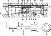
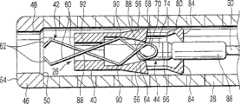
图1是表示本发明的第1实施方式的结扎装置的图。FIG. 1 is a diagram showing a ligation device according to a first embodiment of the present invention.
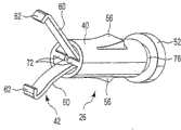
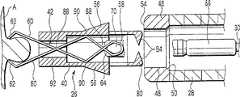
图2是表示本发明的第1实施方式的结扎装置的夹子的立体图。Fig. 2 is a perspective view showing a clip of the ligation device according to the first embodiment of the present invention.
图3是表示本发明的第1实施方式的结扎装置的按压部件的桥接部的形成的立体图。3 is a perspective view showing formation of a bridging portion of a pressing member of the ligation device according to the first embodiment of the present invention.
图4是用于说明基于本发明的第1实施方式的结扎装置的结扎方法中的、将夹子向护套中收纳的收纳工序的纵剖面图。4 is a longitudinal sectional view for explaining a storage step of storing the clip in the sheath in the ligation method by the ligation device according to the first embodiment of the present invention.
图5是用于说明基于本发明的第1实施方式的结扎装置的结扎方法中的、按压部件的进退的限制工序的纵剖面图。5 is a longitudinal sectional view for explaining a step of restricting the advance and retreat of the pressing member in the ligation method by the ligation device according to the first embodiment of the present invention.
图6是用于说明基于本发明的第1实施方式的结扎装置的结扎方法中的、活体组织的把持工序的纵剖面图。6 is a longitudinal sectional view for explaining a step of grasping a living tissue in the ligation method using the ligation device according to the first embodiment of the present invention.
图7是用于说明基于本发明的第1实施方式的结扎装置的结扎方法中的、夹子爪部件的分离工序的纵剖面图。7 is a longitudinal sectional view illustrating a step of separating a clip claw member in a ligation method using the ligation device according to the first embodiment of the present invention.
图8是用于说明基于本发明的第1实施方式的结扎装置的结扎方法中的、夹子的释放工序的纵剖面图。8 is a longitudinal sectional view for explaining a clip releasing step in a ligation method using the ligation device according to the first embodiment of the present invention.
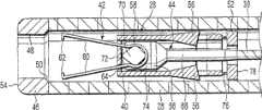
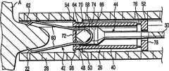
图9示出本发明第2实施方式的结扎装置的前端部,是用于说明基于该结扎装置的结扎方法中的、将夹子向护套中收纳的收纳工序的纵剖面图。9 shows a front end portion of a ligation device according to a second embodiment of the present invention, and is a longitudinal sectional view for explaining a storage step of storing a clip in a sheath in a ligation method using the ligation device.
图10是用于说明基于本发明的第2实施方式的结扎装置的结扎方法中的、按压部件的进退的限制工序的纵剖面图。10 is a longitudinal sectional view illustrating a step of restricting the advance and retreat of the pressing member in the ligation method of the ligation device according to the second embodiment of the present invention.
图11是用于说明基于本发明的第2实施方式的结扎装置的结扎方法中的、活体组织的把持工序的纵剖面图。11 is a longitudinal sectional view for explaining a step of grasping living tissue in a ligation method using the ligation device according to the second embodiment of the present invention.
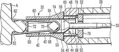
图12是用于说明基于本发明的第2实施方式的结扎装置的结扎方法中的、夹子爪部件及按压部件的分离工序的纵剖面图。12 is a longitudinal sectional view illustrating a step of separating a clip claw member and a pressing member in a ligation method of the ligation device according to the second embodiment of the present invention.
图13是用于说明基于本发明的第2实施方式的结扎装置的结扎方法中的、夹子的释放工序的纵剖面图。13 is a longitudinal sectional view for explaining a clip releasing step in a ligation method using the ligation device according to the second embodiment of the present invention.
图14是表示本发明的第3实施方式的结扎装置的前端部的纵剖面图。Fig. 14 is a longitudinal sectional view showing a distal end portion of a ligation device according to a third embodiment of the present invention.
图15是用于说明基于本发明的第3实施方式的结扎装置的结扎方法中的、活体组织的把持工序的纵剖面图。15 is a longitudinal sectional view for explaining a step of grasping living tissue in a ligation method using the ligation device according to the third embodiment of the present invention.
图16是表示本发明的第4实施方式的结扎装置的前端部的纵剖面图。Fig. 16 is a longitudinal sectional view showing a distal end portion of a ligation device according to a fourth embodiment of the present invention.
图17是用于说明基于本发明的第4实施方式的结扎装置的结扎方法中的、活体组织的把持工序的纵剖面图。17 is a longitudinal sectional view for explaining a step of grasping living tissue in a ligation method using the ligation device according to the fourth embodiment of the present invention.
图18示出本发明第5实施方式的结扎装置的前端部,是用于说明基于该结扎装置的结扎方法中的、按压部件的进退的限制工序的纵剖面图。18 shows the front end of the ligation device according to the fifth embodiment of the present invention, and is a longitudinal sectional view for explaining a step of restricting the advance and retreat of the pressing member in the ligation method using the ligation device.
图19是用于说明基于本发明的第5实施方式的结扎装置的结扎方法中的、按压部件的前进的限制工序的纵剖面图。19 is a longitudinal sectional view for explaining a step of restricting the advancement of the pressing member in the ligation method by the ligation device according to the fifth embodiment of the present invention.
图20是用于说明基于本发明的第5实施方式的结扎装置的结扎方法中的、临时结扎工序的纵剖面图。20 is a longitudinal sectional view for explaining a temporary ligation step in the ligation method using the ligation device according to the fifth embodiment of the present invention.
图21是用于说明基于本发明的第5实施方式的结扎装置的结扎方法中的、正式结扎工序的纵剖面图。21 is a longitudinal sectional view for explaining a main ligation process in the ligation method using the ligation device according to the fifth embodiment of the present invention.
图22是用于说明基于本发明的第5实施方式的结扎装置的结扎方法中的、夹子爪部件及按压部件的分离工序的纵剖面图。22 is a longitudinal sectional view illustrating a step of separating the clip claw member and the pressing member in the ligation method of the ligation device according to the fifth embodiment of the present invention.
图23是用于说明基于本发明的第5实施方式的结扎装置的结扎方法中的、夹子的释放工序的纵剖面图。23 is a longitudinal sectional view for explaining a clip releasing step in a ligation method using the ligation device according to the fifth embodiment of the present invention.
具体实施方式Detailed ways
参照图1至图8说明本发明的第1实施方式。在本实施方式的结扎装置中,在装置本体24中可分离地安装有夹子26。A first embodiment of the present invention will be described with reference to FIGS. 1 to 8 . In the ligation device of this embodiment, a
参照图1,装置本体24具有用于贯穿到内窥镜的通道内并插入体腔内的挠性的护套28。在本实施方式中,护套28通过紧密地卷绕盘管(coil)而形成。用于操作夹子26的操作线30进退自如地贯穿在该护套28中。此外,在护套28的基端部,连接有用于进退操作操作线30的操作部32。该操作部32具有前后细长的操作部本体34,滑块36进退自如地配设在该操作部本体34上。操作线30的基端部连接在该滑块36上,通过使滑块36相对于操作部本体34进退,可使操作线30相对于护套28进退。为了在滑块36的进退操作中保持操作部本体34,在操作部本体34的后端部配设有环状的搭指部38。Referring to FIG. 1 , the
参照图1及图2,夹子26进退自如地收纳在装置本体24的护套28的前端部。该夹子26通过将夹子爪部件42内嵌在按压部件40的大致圆筒形状的本体部内而形成。操作线30的前端部经由连接部件44连接在该夹子爪部件42上,通过使操作线30相对于护套28进退,从而夹子爪部件42与按压部件40一体地相对于护套28进退。Referring to FIGS. 1 and 2 , the
下面,对限制按压部件40在护套28的前端部相对于护套28的进退的进退限制机构进行说明。Next, an advance/retreat restricting mechanism for restricting the advance and retreat of the pressing
首先,说明限制按压部件40相对于护套28的前进的前进限制机构。First, an advancement restricting mechanism for restricting the advancement of the pressing
在盘管的前端部,通过焊接等固定有圆环状的止挡部件46,该止挡部件46具有与盘管的外径大致相等的外径,并且具有比盘管的内径小的内径。即,护套28的前端做成凸缘形状,在护套28的前端形成有内径减小的护套小径部48。利用该护套小径部48的后端侧形成前进限制止挡50。另一方面,在按压部件40的后端部形成有外径增大的前进限制大径部52。通过该前进限制大径部52与前进限制止挡50的抵接,来限制按压部件40相对于护套28的前进。An
接着,说明限制按压部件40相对于护套28后退的后退限制机构。Next, a retreat restriction mechanism for restricting the retreat of the pressing
按压部件40的本体部的外径小于护套小径部48的内径,按压部件40可从护套28的前端突出。此外,利用护套小径部48的前端侧形成后退限制止挡54。另一方面,多个翼部56有弹性地且可扩开和缩闭地配设在按压部件40上。即,在按压部件40中,在沿前后方向延伸设置的切槽中收纳有具有弹性的翼部56,在切槽的前端部,翼部56的前端部与按压部件40的本体部连接。翼部56的后端部能够以该翼部56的前端部和按压部件40的本体部的连接部为支点弹性地转动。此外,翼部56在没有被施加外力的自然状态下扩开。The outer diameter of the main body portion of the pressing
在按压部件40被收纳于护套28中的情况下,翼部56受到护套28的内周面的作用力而向切槽的内部折叠。此外,在按压部件40从护套28的前端部突出的情况下,翼部56借助于弹性而扩开。通过该扩开后的翼部56与后退限制止挡54的抵接,来限制按压部件40相对于护套28的后退。When the pressing
此外,护套小径部48的中心轴方向的长度尺寸稍稍短于按压部件40的前进限制大径部52的前端面与扩开后的翼部56的后端面之间的长度。即,在使夹子26相对于护套28前进的情况下,在按压部件40的前进限制大径部52与前进限制止挡50抵接的时候,翼部56扩开。In addition, the length dimension of the sheath small-
下面,说明夹子爪部件42的开闭机构。Next, the opening and closing mechanism of the
夹子爪部件42通过如下方式形成,即,将不锈钢制的带状部件以中央部的折弯部分成为圆弧形状的方式折弯成V字形状,并且,将V字形状的一对前端部以相互面对的方式向内侧折弯。在这里,利用夹子爪部件42的圆弧形状的折弯部分形成与连接部件44卡合的卡合部58。此外,利用从圆弧形状的折弯部分突出的一对腕状部分形成相互开闭来把持活体组织的一对臂部60,利用一对腕状部分的前端部的钩状部分形成穿刺活体组织的爪部62。The
将操作线30的前端部与夹子爪部件42连接起来的连接部件44具有将半圆柱状部64、大圆柱状部66及小圆柱状部68从前端侧顺次大致同轴地连接的形态,并且该连接部件44被收纳在按压部件40内。半圆柱状部64具有将外径与大圆柱状部66的外径大致相等的圆柱形状用包含中心轴的平面分割后的一侧的形状。此外,在半圆柱状部64的平面部上突出设置有泪珠形(teardrop)的卡合支撑部70,夹子爪部件42的卡合部58卷设并卡装在该卡合支撑部70上。另外,在大圆柱状部66的后端部,形成朝向后端侧外径减小的锥状,在该锥状的后端部连接有小圆柱状部68,该小圆柱状部68具有比大圆柱状部66的外径小的外径。此外,操作线30的前端部通过粘结、焊接等连接在小圆柱状部68的基端部。在这里,在按压部件40相对于护套28的进退被限制的情况下,通过使操作线30相对于护套28进退,从而连接部件44、即夹子爪部件42相对于按压部件40进退。The
在按压部件40的前端部,以横穿前端开口的方式沿直径方向架设有桥接部72。前端开口被桥接部72分割为两个,夹子爪部件42的一对臂部60分别滑动自如地贯穿到这一对分割开口中。此外,通过夹子爪部件42相对于按压部件40的前进,一对臂部60受到桥接部72的作用力而打开,从而夹子爪部件42打开。此外,如图3所示,桥接部72可以通过将在按压部件40的前端面上沿着中心轴方向关于中心轴对称地突出设置的长板状片向内侧折弯而形成。另一方面,通过夹子爪部件42相对于按压部件40的后退,夹子爪部件42被拉进按压部件40中,从而夹子爪部件42通过按压部件40而闭合。On the front end portion of the pressing
下面,对从护套28的前端部释放夹子26的释放机构进行说明。Next, a release mechanism for releasing the
如上所述,夹子爪部件42与操作线30的前端部通过连接部件44连接起来。此外,在连接部件44的半圆柱状部64中,卡合支撑部70与大圆柱状部66之间的部分可以断裂,形成第1断裂部74。此外,通过将半圆柱状部64的外径缩小而使其强度变脆弱,也可以形成第1断裂部74。在按压部件40相对于护套28的后退被限制、并且夹子爪部件42被充分地拉进按压部件40中的情况下,通过使操作线30相对于护套28进一步进退,从而第1断裂部74断裂。As described above, the
此外,在按压部件40的前进限制大径部52与翼部56之间,形成有可断裂的第2断裂部76。该第2断裂部76通过强度弱的脆弱部形成,关于与按压部件40的中心轴方向正交的截面,脆弱部的截面积小于按压部件40的本体部的截面积。在本实施方式中,通过使按压部件40的壁厚变薄而形成脆弱部,但是,也可以通过形成切槽等来形成脆弱部。在该第2断裂部76的后端侧,形成有内径相对于按压部件40的本体部减小的卡定小径部78。此外,在第1断裂部74断裂的情况下,通过使操作线30相对于护套28后退,从而作为卡定大径部的大圆柱状部66的后端侧的锥状卡定于按压部件40的卡定小径部78,对卡定小径部78向后端侧施力,从而使第2断裂部76断裂。In addition, a breakable
接着,参照图4至图8,说明基于本实施方式的结扎装置的活体组织的结扎方法。在本实施方式中,将结扎装置与内窥镜组合起来使用。Next, a method of ligation of living tissue using the ligation device of this embodiment will be described with reference to FIGS. 4 to 8 . In this embodiment, a ligation device is used in combination with an endoscope.
参照图4,夹子26以完全被收纳的方式安装在护套28的前端部中。在该安装状态下,夹子爪部件42不会露出到外部,按压部件40的翼部56通过护套28的内周面弹性地缩闭而折叠在切槽中。此外,夹子爪部件42相对于按压部件40配置在最前端的位置,虽然桥接部72对夹子爪部件42以使其最大限度地打开的方式施力,但是该夹子爪部件42通过护套28的内周面弹性地闭合。Referring to FIG. 4 , the
接着,将护套28贯穿到插入体腔内的内窥镜的通道中,使护套28的前端部从通道的前端部突出并向体腔内插入。此外,在内窥镜观察下,将护套28的前端部向活体组织的结扎对象部位A的附近移动。此外,也可以利用内窥镜以外的引导设备的通道将护套28向体腔内插入。Next, the
参照图5,在操作部32中,使滑块36相对于操作部本体34前进,从而通过操作线30使夹子26相对于护套28前进,使夹子26从护套28的前端部突出。这时,按压部件40的前进限制大径部52与护套小径部48的前进限制止挡50抵接,限制按压部件40从护套28的前端部进一步地突出。同时,通过使按压部件40从护套28的前端部突出,从而基于护套28的内周面的限制被解除,按压部件40的翼部56扩开,扩开后的翼部56与护套28的前端的后退限制止挡54抵接,由此,限制按压部件40没入护套28的前端部。另外,护套28的内周面对夹子爪部件42的施力被解除,从而夹子爪部件42最大限度地打开。Referring to FIG. 5 , in the
参照图6,将结扎装置的护套28相对于内窥镜压入,在内窥镜观察下,将夹子爪部件42的前端部按压到活体组织的结扎对象部位A。然后,使滑块36相对于结扎装置的操作部本体34后退。其结果是,夹子爪部件42通过操作线30而相对于按压部件40后退,夹子爪部件42被拉进按压部件40中,夹子爪部件42通过按压部件40闭合。此外,夹子爪部件42的爪部62穿刺结扎对象部位A,活体组织被夹子爪部件42把持。通过将夹子爪部件42充分地拉进按压部件40中,从而夹子爪部件42充分地闭合,活体组织被结扎。Referring to FIG. 6 , the
在这里,在止血目的的结扎中,如果对结扎对象部位A适当地结扎,则可以解决出血问题,但是在不能适当地结扎的情况下,就不能解决出血问题,所以需要进行再结扎。在进行再结扎的情况下,使滑块36相对于结扎装置的操作部本体34前进。其结果是,夹子爪部件42通过操作线30而相对于按压部件40前进,从而夹子爪部件42受到桥接部72的作用力而打开。这样,结扎对象部位A被释放。之后,反复进行上述操作,直到适当地对结扎对象部位A进行结扎为止。Here, in the ligation for the purpose of hemostasis, if the ligation target site A is properly ligated, the bleeding problem can be solved, but if the ligation cannot be done properly, the bleeding problem cannot be solved, so re-ligation is required. When performing religation, the
参照图7,在结扎对象部位A被适当地结扎、夹子爪部件42被充分地拉进按压部件40中的状态下,进一步使滑块36相对于操作部本体34后退。其结果是,连接部件44的第1断裂部74断裂,夹子爪部件42与操作线30分离。Referring to FIG. 7 , the
参照图8,在第1断裂部74断裂之后,进一步使滑块36相对于操作部本体34后退。其结果是,连接部件44的大圆柱状部66卡定于按压部件40的卡定小径部78,大圆柱状部66对卡定小径部78向后端侧施力,从而按压部件40的脆弱部断裂。这样,按压部件40的前端侧从护套28的前端部分离。Referring to FIG. 8 , after the
之后,将护套28相对于内窥镜拔出,将夹子26从护套28的前端部释放。在这里,夹子爪部件42借助于摩擦阻力卡装在按压部件40中,保持在闭合的状态。因而,该夹子26以对结扎对象部位A结扎的状态留置在体腔内。Thereafter, the
从而,本实施方式的结扎装置可以获得下面的效果。在本实施方式的结扎装置中,夹子26以夹子爪部件42不会露出到外部的方式被收纳在护套28中,通过将护套28贯穿内窥镜等的通道,从而向体腔内插入。因而,可防止通道内壁被夹子爪部件42损伤,并且,可避免夹子爪部件42挂在通道内壁上而使所需的插入力量增大。另外,夹子爪部件42相对于按压部件40进退,通过与按压部件40的相互作用而开闭,为了能够通过夹子26对活体组织进行结扎,进退限制机构限制按压部件40在护套28的前端部相对于护套28的进退,可以通过操作线30相对于护套28的进退,使夹子爪部件42相对于按压部件40进退。因而,可通过夹子爪部件42对结扎对象部位A重新进行结扎。这样,本实施方式的结扎装置最适合于体腔内的活体组织的结扎。Therefore, the ligation device of this embodiment can obtain the following effects. In the ligation device of this embodiment, the
另外,在本实施方式的结扎装置中,通过使滑块36相对于操作部本体34的前进,从而夹子26从护套28的前端部突出,夹子爪部件42打开,接着,通过使滑块36相对于操作部本体34后退,从而夹子爪部件42闭合,夹子26从护套28的前端部被释放。这样,结扎装置的基端部的操作方向和结扎装置的前端部的动作方向彼此一致,可进行结扎装置的直观的操作。In addition, in the ligation device of this embodiment, by advancing the
另外,在本实施方式的结扎装置的夹子26中,在夹子爪部件42相对于按压部件40前进的情况下,夹子爪部件42被桥接部72强制地打开。在没有形成这种桥接部72的情况下,仅通过对夹子爪部件42施加使其扩开的力来打开夹子爪部件42,从而难以可靠地打开夹子爪部件42,但是,在本实施方式中,能可靠地打开夹子爪部件42。In addition, in the
图9至图13示出本发明的第2实施方式。对于具有与第1实施方式同样功能的结构标以相同的标号,并省略对其的说明。9 to 13 show a second embodiment of the present invention. Components having the same functions as those in the first embodiment are given the same reference numerals, and their descriptions are omitted.
下面,对限制按压部件40的前进的前进限制机构以及释放夹子26的释放机构进行说明。Next, the advance restriction mechanism for restricting the advance of the pressing
在按压部件40的后端部,弹性地且可扩径和缩径地形成有扩缩径部80。处于扩径状态的扩缩径部80具有比护套小径部48的内径大的外径,具有与上述前进限制大径部52(参照图1至图8)同样的功能。另一方面,处于缩径状态的扩缩径部80与按压部件40的大致圆筒形状的本体部的外径基本相等,具有比护套小径部48的内径小的外径,可通过护套小径部48。At the rear end portion of the pressing
扩缩径部80具有朝向按压部件40的径向内侧突出的突出部84。此外,在操作线30的前端部,一体地或分体地形成有外径大于操作线30的外径的大致圆柱状的施力部86。此外,与第1实施方式不同,在连接部件44上没有形成小圆柱状部68(参照图1至图8),施力部86的前端部通过粘结、机械地连接或焊接等连接在大圆柱状部66的后端部。该施力部86被插入按压部件40内,对凸起部84朝按压部件40的径向外侧施力,将扩缩径部80保持在扩径状态。在这里,施力部86的中心轴方向的长度被设定成,在使夹子爪部件42相对于按压部件40进退而开闭时,始终处于凸起部84的径向内侧,而将扩缩径部80保持在扩径状态。此外,在连接部件44的第1断裂部74断裂之后,当使操作线30相对于护套28后退、从按压部件40拔出施力部86时,施力部86对凸起部84的施力被解除,扩缩径部80被保持在缩径状态。The diameter-enlarged
下面,说明夹子爪部件42的开闭机构。本实施方式的夹子爪部件42具有一对臂部60相互交叉的两个交叉部分88。在这两个交叉部88之间,各臂部60被折弯而形成山形部分90。另一方面,按压部件40的前端部成为凸缘形状,在按压部件40的前端部,形成有内径小于按压部件40的本体部的内径的开闭小径部92。在本实施方式中,开闭小径部92的前后端部分别做成台阶形状,但是,也可以是斜面(slope)形状等其他形状。在这里,夹子26的朝向宽度方向的各山形部分90之间的距离在没有被施加外力的自然状态下,大于按压部件40的开闭小径部92的内径,但是,既可以大于按压部件40的本体部的内径,也可以小于按压部件40的本体部的内径。此外,通过使夹子爪部件42相对于按压部件40前进,从而各山形部分90被插入开闭小径部92内,朝向按压部件40的径向内侧相互接近,一对臂部60的前端侧打开。另一方面,通过使夹子爪部件42相对于按压部件40后退,从而各山形部分90被从开闭小径部92拔出,朝向按压部件40的径向外侧相互离开,一对臂部60的前端侧闭合。Next, the opening and closing mechanism of the
接着,参照图9至图13,说明基于本实施方式的结扎装置的活体组织的结扎方法。下面,对与第1实施方式同样的工序,省略详细的说明。Next, with reference to FIGS. 9 to 13 , a method for ligation of living tissue using the ligation device of this embodiment will be described. Hereinafter, detailed descriptions of steps similar to those of the first embodiment will be omitted.
参照图9,将夹子26收纳在护套28的前端部中,将护套28的前端部插入体腔内,配置在结扎对象部位A的附近。Referring to FIG. 9 , the
参照图10,操作线30的前端部的施力部86对突起部84朝按压部件40的径向外侧施力,从而扩缩径部80被保持在扩径状态。在该状态下,使夹子26从护套28的前端部突出,通过进退限制机构,限制按压部件40相对于护套28的前端部的进退。此外,通过使滑块36相对于操作部本体34前进,从而通过操作线30使夹子爪部件42相对于按压部件40前进。其结果是,夹子爪部件42的各臂部60的山形部分90插入开闭小径部92,朝向按压部件40的径向内侧相互接近,一对臂部60的前端侧打开。Referring to FIG. 10 , the urging
参照图11,将夹子爪部件42的前端部按压到活体组织的结扎对象部位A。然后,使滑块36相对于结扎装置的操作部本体34后退,从而通过操作线30使夹子爪部件42相对于按压部件40后退。其结果是,夹子爪部件42的各臂部60的山形部分90被从开闭小径部92中拔出,朝向按压部件40的径向外侧相互离开,一对臂部60的前端侧闭合。这样,活体组织被结扎。在不能对结扎对象部位A适当地进行结扎的情况下,反复进行上述开闭操作,直到结扎对象部位A被适当地结扎为止。Referring to FIG. 11 , the front end portion of the
参照图12,在结扎对象部位A被适当地结扎、夹子爪部件42被充分地拉进按压部件40中的状态下,使滑块36相对于操作部本体34后退,从而使连接部件44的第1断裂部74断裂,使夹子爪部件42与操作线30分离。并且,在第1断裂部74断裂之后,进一步使滑块36相对于操作部本体34后退。其结果是,操作线30的前端部的施力部86被从按压部件40拔出,施力部86对凸起部84的施力被解除,扩缩径部80向缩径状态弹性地转移,而可通过护套小径部48。这样,按压部件40从护套28的前端部分离。Referring to FIG. 12 , in a state where the ligation target site A is properly ligated and the
参照图13,将护套28相对于内窥镜拔出,将夹子26从护套28的前端部释放。Referring to FIG. 13 , the
从而,本实施方式的结扎装置可以获得下面的效果。在本实施方式的夹子爪部件42的开闭机构中,通过使夹子爪部件42相对于按压部件40前进,从而夹子爪部件42的各臂部60的山形部分90被插入到按压部件40的开闭小径部92中,通过开闭小径部92相互接近,一对臂部60打开。另一方面,通过使夹子爪部件42相对于按压部件40后退,从而山形部分90被从开闭小径部92拔出而相互离开,一对臂部60闭合。因而,即使在反复进行夹子爪部件42的开闭的情况下,无论夹子爪部件42的材质如何,都可以防止由夹子爪部件42的塑性变形引起的打开宽度的减小,可持久地反复进行夹子爪部件42的开闭。Therefore, the ligation device of this embodiment can obtain the following effects. In the opening and closing mechanism of the
另外,在本实施方式的夹子26的释放机构中,通过使滑块36相对于操作部本体34后退,从而施力部86通过操作线30从按压部件40中被拔出,施力部86对凸起部84的施力被解除,扩缩径部80向缩径状态弹性地转移,而可通过护套小径部48。这样,借助于弹性变形进行按压部件40与护套28的前端部之间的分离,与通过塑性变形进行这种分离的情况相比,能可靠地进行分离,同时,可减少所需的操作力量。In addition, in the release mechanism of the
图14及图15示出本发明的第3实施方式。对具有与第1实施方式同样功能的结构标以相同的标号,并省略对其的说明。14 and 15 show a third embodiment of the present invention. Components having the same functions as those in the first embodiment are denoted by the same reference numerals, and their descriptions are omitted.
参照图14,本实施方式的按压部件40具有使夹子爪部件42相对于按压部件40前进的弹性部。该弹性部通过突出设置在按压部件40的内周面上的板簧94形成。该板簧94既可以与按压部件40一体地形成,也可以与按压部件40分体地形成并通过粘结、机械地连接或焊接等与按压部件40连接起来。与第1实施方式同样,夹子爪部件42相对于按压部件40配置在最前端的位置,板簧94配设在连接部件44的大圆柱状部66的后端部的位置。此外,在使操作线30相对于护套28后退、使连接部件44相对于按压部件40后退的情况下,板簧94借助于连接部件44的大圆柱状部66的锥状而弹性变形,从而产生使连接部件44前进的回弹力。Referring to FIG. 14 , the pressing
接着,参照14及图15,说明基于本实施方式的结扎装置的活体组织的结扎方法。下面,对于与第1实施方式同样的工序,省略详细的说明。Next, with reference to FIG. 14 and FIG. 15 , a method of ligation of living tissue using the ligation device of this embodiment will be described. Hereinafter, detailed descriptions of steps similar to those of the first embodiment will be omitted.
使滑块36相对于结扎装置的操作部本体34后退,从而使夹子爪部件42闭合来把持活体组织。这时,连接部件44相对于按压部件40后退,板簧94借助于连接部件44的大圆柱状部66的锥状而弹性变形,产生使连接部件44前进的回弹力。在不能对结扎对象部位A适当地进行结扎的情况下,解除对滑块36的操作力。其结果是,借助于板簧94的回弹力,夹子爪部件42、连接部件44及操作线30相对于按压部件40或护套28自动地前进,夹子爪部件42打开,结扎对象部位A被释放。之后,反复进行上述操作,直到结扎对象部位A被适当地结扎为止。The
从而,本实施方式的结扎装置可以获得下面的效果。在经由操作线30将滑块36相对于操作本体部的前进操作传递给连接部件44的结构中,存在因操作线30的松弛而不能充分将操作力传递给连接部件44、从而不能可靠地使连接部件44前进的情况。在本实施方式的结扎装置中,借助于按压部件40的板簧94的弹力,使夹子爪部件42、连接部件44及操作线30相对于按压部件40或护套28前进。因而,能可靠地使连接部件44前进,从而能够可靠地开闭夹子爪部件42。Therefore, the ligation device of this embodiment can obtain the following effects. In the structure in which the forward operation of the
另外,仅通过解除对滑块36的操作力,就可以借助于板簧94的弹力,使连接部件44相对于按压部件40自动地前进。因而,不需要进行滑块36相对于操作本体部34的前进操作,可非常简便地进行结扎装置的操作。In addition, only by releasing the operating force on the
此外,本实施例的弹性部也可适用于第2实施方式。In addition, the elastic part of this Example is also applicable to 2nd Embodiment.
图16及图17示出本发明的第4实施方式。对于具有与第3实施方式同样功能的结构标以相同的标号,并省略对其的说明。16 and 17 show a fourth embodiment of the present invention. Components having the same functions as those in the third embodiment are denoted by the same reference numerals, and description thereof will be omitted.
本实施方式的弹性部由螺旋弹簧96形成。该螺旋弹簧96在连接部件44的大圆柱状部66的锥状的前端部与按压部件40的卡定小径部78的前端面之间,内装在按压部件44中并且外装在连接部件44上。在对滑块36的操作力被解除的情况下,夹子爪部件42相对于按压部件40配置在最前端的位置,螺旋弹簧96没有被压缩。此外,通过使操作线30相对于护套28后退,使连接部件44相对于按压部件40后退,从而螺旋弹簧96被锥状的前端部与卡定小径部78的前端面压缩,产生使连接部件44前进的回弹力。基于本实施方式的结扎装置的活体组织的结扎方法,与基于第3实施方式的结扎装置的活体组织的结扎方法相同。The elastic portion in this embodiment is formed of a
在本实施方式中,使用螺旋弹簧96作为弹性部,因此,与第3实施方式那样使用板簧94的情况相比较,能可靠地获得大的弹力。因而,可以对连接部件44向前端侧施加大的力,能够可靠地打开夹子爪部件42。In this embodiment, since the
图18至图22示出本发明的第5实施方式。对于具有与第1实施方式同样功能的结构标以相同的标号,并省略对其的说明。18 to 22 show a fifth embodiment of the present invention. Components having the same functions as those in the first embodiment are given the same reference numerals, and their descriptions are omitted.
下面,说明对按压部件40的进退进行限制的进退限制机构。Next, the advance and retreat restriction mechanism for restricting the advance and retreat of the pressing
本实施方式的护套小径部48配置在距护套28的前端预定距离的后端侧。该护套小径部48通过从外周面侧对护套28挤压(潰す)以使其向径向内侧突出而形成,或者,通过在护套28的内周面连接其他部件而形成。本实施方式的护套小径部48作为前进限制护套小径部及后退限制护套小径部发挥功能。即,利用护套小径部48的后端侧形成限制按压部件40的前进的前进限制止挡50。另一方面,利用护套小径部48的前端侧形成限制按压部件40的后退的后退限制止挡54。此外,按压部件40的前端部做成凸缘形状,在按压部件40的前端部形成有外径增大的后退限制大径部98。此外,通过使按压部件40的后退限制大径部98与护套小径部48的后退限制止挡54抵接,从而限制按压部件40相对于护套28的后退。The sheath small-
在这里,在按压部件40的前进限制大径部52与护套小径部48的前进限制止挡50抵接的情况下,按压部件40相对于护套28位于最前端的位置,将该按压部件40的位置称作前端限制位置。此外,护套28的前端与护套小径部48的前进限制止挡50之间的长度,和按压部件40的前端部与前进限制大径部52的前端面之间的长度大致相等或比其稍短。即,在按压部件40配置在前端限制位置的情况下,按压部件40的前端部被配置在护套28前端的位置,或稍稍从护套28的前端突出。另一方面,在按压部件40的后退限制大径部98与护套小径部48的后退限制止挡54抵接的情况下,按压部件40相对于护套28位于最后端的位置,将该按压部件40的位置称作后端限制位置。Here, when the advance limiting large-
在按压部件40被配置在前端限制位置的情况下,通过使操作线30相对于护套28前进,从而夹子爪部件42相对于按压部件40前进,通过使操作线30相对于护套28后退,从而按压部件40与夹子爪部件42一体地相对于护套28后退。另一方面,在按压部件40被配置在后端限制位置的情况下,通过使操作线30相对于护套28后退,从而夹子爪部件42相对于按压部件40后退,通过使操作线30相对于护套28前进,从而按压部件40与夹子爪部件42一体地相对于护套28前进。在按压部件40被配置于前端限制位置与后端限制位置之间的情况下,通过使操作线30相对于护套28进退,从而按压部件40与夹子爪部件42一体地相对于护套28进退,夹子爪部件42受到护套28的内周面的作用力而开闭。When the pressing
接着,参照图18至图22,说明基于本实施方式的结扎装置的结扎方法。下面,对于与第1实施方式同样的工序,省略详细的说明。Next, a ligation method using the ligation device of this embodiment will be described with reference to FIGS. 18 to 22 . Hereinafter, detailed descriptions of steps similar to those of the first embodiment will be omitted.
参照图18,将夹子26安装在护套28的前端部,使滑块36相对于操作部本体34后退。其结果是,夹子26相对于护套28后退,按压部件40被配置在后端限制位置,进而夹子爪部件42相对于按压部件40后退,夹子爪部件42以夹子爪部件42不会露出到外部的方式被收纳在护套28中。在该状态下,将护套28的前端部插入体腔内,配置在活体组织的结扎对象部位A的附近。Referring to FIG. 18 , the
参照图19,使滑块36相对于操作部本体34前进,从而使夹子26相对于护套28前进,将按压部件40配置于前端限制位置,进而,使夹子爪部件42相对于按压部件40前进并配置在最前端的位置,最大限度地打开夹子爪部件42。Referring to FIG. 19 , the
参照图20,将夹子爪部件42的前端部按压到结扎对象部位A之后,使滑块36相对于操作部本体34后退。其结果是,夹子26相对于护套28后退,夹子爪部件42通过护套28的内周面闭合,结扎对象部位A被临时结扎。在这里,在不能适当地进行临时结扎的情况下,进行再结扎。即,使滑块36相对于操作部本体34前进,从而使夹子26相对于护套28前进,解除护套28的内周面对夹子爪部件42的施力,打开夹子爪部件42,释放结扎对象部位A。然后,再次进行临时结扎。Referring to FIG. 20 , after the front end portion of the
参照图21,在适当地进行临时结扎的情况下,转移到正式结扎。即,使滑块36相对于操作部本体34后退,从而使夹子26相对于护套28后退,将按压部件40配置于后端限制位置。进而,使滑块36相对于操作部本体34后退,与第1实施方式同样,对结扎对象部位A进行正式结扎。Referring to FIG. 21 , when the temporary ligation is properly performed, it is transferred to the final ligation. That is, the
参照22及图23,与第1实施方式同样,将夹子爪部件42从操作线30的前端部分离,同时,将按压部件40从护套28的前端部分离,将夹子26从护套28的前端部分离。22 and FIG. 23 , similar to the first embodiment, the
从而,本实施方式的结扎装置可以获得下面的效果。在如第1实施方式那样,使用可弹性地动作的翼部56作为按压部件40的后退限制机构的情况下,在将夹子26收纳在护套28的前端部中、将翼部56折叠在按压部件40的状态下,翼部56的弹性会劣化,从而在使按压部件40从护套28的前端部突出的情况下,翼部56不能充分地扩开,存在不能充分地发挥作为后退限制机构的功能的情况。在本实施方式中,由于使用固定的后退限制大径部98作为按压部件40的后退限制机构,所以,可避免上述情况发生,能可靠地限制按压部件40的后退。Therefore, the ligation device of this embodiment can obtain the following effects. In the case of using the elastically
另外,由于在夹子26从护套28前端分离之后也需要保持对活体组织进行结扎的状态,所以为了使夹子爪部件42与按压部件40彼此可靠地卡装在一起,在夹子爪部件42与按压部件40之间需要某种程度的摩擦力。但是,若摩擦力过大,则会妨碍夹子爪部件42相对于按压部件40的前进,也有可能妨碍夹子爪部件42扩开。在本实施方式中,在有可能反复进行的临时结扎中,通过使夹子26相对于护套28进退来进行夹子爪部件42的开闭,从而可避免因夹子爪部件42与按压部件40之间的摩擦力妨碍夹子爪部件42扩开。In addition, since it is necessary to maintain the state of ligating the living tissue even after the
Claims (21)
Translated fromChineseApplications Claiming Priority (5)
| Application Number | Priority Date | Filing Date | Title |
|---|---|---|---|
| JP374333/2004 | 2004-12-24 | ||
| JP2004374333 | 2004-12-24 | ||
| JP2005232253AJP4758173B2 (en) | 2004-12-24 | 2005-08-10 | Ligation device |
| JP232253/2005 | 2005-08-10 | ||
| PCT/JP2005/023652WO2006068242A1 (en) | 2004-12-24 | 2005-12-22 | Ligation device |
Related Child Applications (1)
| Application Number | Title | Priority Date | Filing Date |
|---|---|---|---|
| CN2009102211275ADivisionCN101695452B (en) | 2004-12-24 | 2005-12-22 | Ligation apparatus |
Publications (2)
| Publication Number | Publication Date |
|---|---|
| CN101087564A CN101087564A (en) | 2007-12-12 |
| CN101087564Btrue CN101087564B (en) | 2010-06-02 |
Family
ID=38938200
Family Applications (1)
| Application Number | Title | Priority Date | Filing Date |
|---|---|---|---|
| CN2005800444317AActiveCN101087564B (en) | 2004-12-24 | 2005-12-22 | Ligation device |
Country Status (2)
| Country | Link |
|---|---|
| JP (1) | JP4870139B2 (en) |
| CN (1) | CN101087564B (en) |
Cited By (1)
| Publication number | Priority date | Publication date | Assignee | Title |
|---|---|---|---|---|
| US9492176B2 (en) | 2011-11-11 | 2016-11-15 | Jian Zhu | Clamping and ligation device |
Families Citing this family (18)
| Publication number | Priority date | Publication date | Assignee | Title |
|---|---|---|---|---|
| CN101606856B (en)* | 2009-07-07 | 2011-12-28 | 中国人民解放军第三军医大学第二附属医院 | Biological tissue clamp device |
| JP5486983B2 (en)* | 2010-03-29 | 2014-05-07 | 富士フイルム株式会社 | Ligation device |
| JP5588711B2 (en)* | 2010-03-30 | 2014-09-10 | 富士フイルム株式会社 | Ligation device |
| JP5343113B2 (en)* | 2011-09-15 | 2013-11-13 | 富士フイルム株式会社 | Clip unit and ligating apparatus using the same |
| JP5480454B1 (en) | 2012-07-20 | 2014-04-23 | オリンパスメディカルシステムズ株式会社 | Hemostatic clip |
| US20140088616A1 (en)* | 2012-09-24 | 2014-03-27 | Boston Scientific Scimed, Inc. | Release mechanism for hemostatic clip |
| WO2016027523A1 (en)* | 2014-08-19 | 2016-02-25 | オリンパス株式会社 | Medical treatment instrument |
| CN105310738B (en)* | 2014-12-24 | 2017-12-26 | 石益海 | A kind of tear-away clamping device of three-clove style |
| US10470775B2 (en)* | 2015-10-23 | 2019-11-12 | Hangzhou Ags Medtech Co., Ltd. | Ligation device |
| JP6274233B2 (en)* | 2016-02-23 | 2018-02-07 | 住友ベークライト株式会社 | Clip cartridge system |
| JP6663992B2 (en)* | 2016-07-11 | 2020-03-13 | オリンパス株式会社 | Endoscope treatment tool |
| WO2019070606A1 (en)* | 2017-10-02 | 2019-04-11 | Boston Scientific Scimed, Inc. | Devices and methods for tissue retraction |
| JP7247218B2 (en)* | 2018-12-11 | 2023-03-28 | オリンパス株式会社 | How to release medical devices and clip units |
| CN118986456A (en)* | 2018-12-28 | 2024-11-22 | 奥林巴斯株式会社 | Ligature device |
| JP7183854B2 (en)* | 2019-02-20 | 2022-12-06 | 住友ベークライト株式会社 | Endoscope clip device |
| CN110090065B (en)* | 2019-04-25 | 2024-05-31 | 安徽医科大学第一附属医院 | Chuck release pincers |
| CN112704535B (en)* | 2019-10-25 | 2022-11-25 | 苏州英途康医疗科技有限公司 | Clamping device and surgical operation instrument |
| US20220386856A1 (en)* | 2019-11-14 | 2022-12-08 | Hangzhou Ags Medtech Co., Ltd. | Multi-processing device for an endoscope and use method thereof |
Family Cites Families (8)
| Publication number | Priority date | Publication date | Assignee | Title |
|---|---|---|---|---|
| JPS6092510A (en)* | 1983-10-25 | 1985-05-24 | Kinjiyou Gomme Kk | Method and apparatus for detection of position of vapor drain |
| JPS63288147A (en)* | 1987-05-21 | 1988-11-25 | Olympus Optical Co Ltd | Clip device |
| JPH08126648A (en)* | 1994-11-02 | 1996-05-21 | Olympus Optical Co Ltd | Treatment instrument for endoscope |
| JP3776529B2 (en)* | 1996-02-29 | 2006-05-17 | オリンパス株式会社 | Clip device |
| GB9722203D0 (en)* | 1997-10-21 | 1997-12-17 | Univ London | Surgical clip |
| JP4080708B2 (en)* | 2001-06-19 | 2008-04-23 | ペンタックス株式会社 | Endoscopic clip device |
| JP3914462B2 (en)* | 2001-11-15 | 2007-05-16 | ペンタックス株式会社 | Endoscopic clip device |
| JP4311953B2 (en)* | 2003-02-20 | 2009-08-12 | Hoya株式会社 | Endoscopic clip device |
- 2005
- 2005-12-22CNCN2005800444317Apatent/CN101087564B/enactiveActive
- 2008
- 2008-11-20JPJP2008296824Apatent/JP4870139B2/ennot_activeExpired - Lifetime
Non-Patent Citations (2)
| Title |
|---|
| JP特开2004-121485A 2004.04.22 |
| JP特开2004-305231A 2004.11.04 |
Cited By (1)
| Publication number | Priority date | Publication date | Assignee | Title |
|---|---|---|---|---|
| US9492176B2 (en) | 2011-11-11 | 2016-11-15 | Jian Zhu | Clamping and ligation device |
Also Published As
| Publication number | Publication date |
|---|---|
| JP2009072611A (en) | 2009-04-09 |
| CN101087564A (en) | 2007-12-12 |
| JP4870139B2 (en) | 2012-02-08 |
Similar Documents
| Publication | Publication Date | Title |
|---|---|---|
| CN101695452A (en) | Ligation apparatus | |
| CN101087564B (en) | Ligation device | |
| EP1493392B1 (en) | Ligation apparatus | |
| US6776783B1 (en) | Surgical clips and apparatus and method for clip placement | |
| US6814742B2 (en) | Physiological tissue clipping apparatus, clipping method and clip unit mounting method | |
| JP2006198388A5 (en) | ||
| JPH09289989A (en) | Clip device | |
| JP5486983B2 (en) | Ligation device | |
| CN112955082B (en) | Endoscope clamp | |
| CN113710169B (en) | Hemostatic Clip Deployment Device | |
| JP4394634B2 (en) | Endoscope clip removal device | |
| JP4709822B2 (en) | Biological tissue clip device | |
| WO2017017587A2 (en) | Thickness-adjustable hemostatic clips, clip appliers, and applications thereof | |
| JP7322185B2 (en) | Two-stage hemostatic clip deployment mechanism for removal of sloughing | |
| JP4472719B2 (en) | Biological tissue clip device | |
| CN114144129A (en) | Reloadable clip with flared bladder deformation | |
| WO2012039164A1 (en) | Ligature device and clip unit used therein | |
| JP2007196012A (en) | Clip device for living body tissue | |
| JP2023099702A (en) | Clip delivery device and clip unit | |
| JP4653184B2 (en) | Biological tissue clip device | |
| WO2021084728A1 (en) | Medical device | |
| JP4472720B2 (en) | Biological tissue clip device | |
| US20230149017A1 (en) | Endoscopic suturing method and medical instrument | |
| JP7508490B2 (en) | Ligation Device | |
| US20250000499A1 (en) | Clip device and clip system |
Legal Events
| Date | Code | Title | Description |
|---|---|---|---|
| C06 | Publication | ||
| PB01 | Publication | ||
| C10 | Entry into substantive examination | ||
| SE01 | Entry into force of request for substantive examination | ||
| C14 | Grant of patent or utility model | ||
| GR01 | Patent grant | ||
| C41 | Transfer of patent application or patent right or utility model | ||
| TR01 | Transfer of patent right | Effective date of registration:20160301 Address after:Tokyo, Japan Patentee after:Olympus Corporation Address before:Tokyo, Japan Patentee before:Olympus Corporation Patentee before:Olympus Medical Systems Corp. |