CN101084423B - Knock Deflagration Determination Device for Internal Combustion Engine - Google Patents
Knock Deflagration Determination Device for Internal Combustion EngineDownload PDFInfo
- Publication number
- CN101084423B CN101084423BCN2005800440759ACN200580044075ACN101084423BCN 101084423 BCN101084423 BCN 101084423BCN 2005800440759 ACN2005800440759 ACN 2005800440759ACN 200580044075 ACN200580044075 ACN 200580044075ACN 101084423 BCN101084423 BCN 101084423B
- Authority
- CN
- China
- Prior art keywords
- waveform
- knock
- vibration
- internal combustion
- engine
- Prior art date
- Legal status (The legal status is an assumption and is not a legal conclusion. Google has not performed a legal analysis and makes no representation as to the accuracy of the status listed.)
- Active
Links
Images


Classifications
- G—PHYSICS
- G01—MEASURING; TESTING
- G01L—MEASURING FORCE, STRESS, TORQUE, WORK, MECHANICAL POWER, MECHANICAL EFFICIENCY, OR FLUID PRESSURE
- G01L23/00—Devices or apparatus for measuring or indicating or recording rapid changes, such as oscillations, in the pressure of steam, gas, or liquid; Indicators for determining work or energy of steam, internal-combustion, or other fluid-pressure engines from the condition of the working fluid
- G01L23/22—Devices or apparatus for measuring or indicating or recording rapid changes, such as oscillations, in the pressure of steam, gas, or liquid; Indicators for determining work or energy of steam, internal-combustion, or other fluid-pressure engines from the condition of the working fluid for detecting or indicating knocks in internal-combustion engines; Units comprising pressure-sensitive members combined with ignitors for firing internal-combustion engines
- G01L23/221—Devices or apparatus for measuring or indicating or recording rapid changes, such as oscillations, in the pressure of steam, gas, or liquid; Indicators for determining work or energy of steam, internal-combustion, or other fluid-pressure engines from the condition of the working fluid for detecting or indicating knocks in internal-combustion engines; Units comprising pressure-sensitive members combined with ignitors for firing internal-combustion engines for detecting or indicating knocks in internal combustion engines
- G01L23/225—Devices or apparatus for measuring or indicating or recording rapid changes, such as oscillations, in the pressure of steam, gas, or liquid; Indicators for determining work or energy of steam, internal-combustion, or other fluid-pressure engines from the condition of the working fluid for detecting or indicating knocks in internal-combustion engines; Units comprising pressure-sensitive members combined with ignitors for firing internal-combustion engines for detecting or indicating knocks in internal combustion engines circuit arrangements therefor
Landscapes
- Chemical & Material Sciences (AREA)
- Engineering & Computer Science (AREA)
- Combustion & Propulsion (AREA)
- Physics & Mathematics (AREA)
- General Physics & Mathematics (AREA)
- Combined Controls Of Internal Combustion Engines (AREA)
- Testing Of Engines (AREA)
- Measurement Of Mechanical Vibrations Or Ultrasonic Waves (AREA)
Abstract
Description
Translated fromChinese技术领域technical field
本发明涉及爆燃(knock)判定装置,特别是用于内燃机的爆燃判定装置,该装置基于内燃机振动波形来判定发动机是否爆燃。The invention relates to a knock judging device, especially a knock judging device for an internal combustion engine, which judges whether the engine is knocking based on the vibration waveform of the internal combustion engine.
背景技术Background technique
常规地,用于检测内燃机爆燃的技术是已知的。日本专利特开No.2001-227400公开了一种用于内燃机的爆燃控制装置,该装置能够准确判定发动机是否爆燃。日本专利特开No.2001-227400所公开的内燃机用爆燃控制装置包含:信号检测器,其检测表示内燃机中所发生振动的波形的信号(或振动波形信号);发生期间检测器,其检测作为发生期间的时间段,在该时间段中,信号检测器检测到的振动波形信号取至少为预定值的值;峰值位置检测器,其检测在由发生期间检测器检测到的发生期间中的峰值位置;爆燃判定器,其基于发生期间与峰值位置之间的关系判定内燃机是否爆燃;爆燃控制器,其根据爆燃判定器的判定结果控制内燃机的运行状态。当峰值位置相对于发生期间处于预定范围内时,爆燃判定器判定爆燃(knocking)发生。Conventionally, techniques for detecting knocking in internal combustion engines are known. Japanese Patent Laid-Open No. 2001-227400 discloses a knock control device for an internal combustion engine, which can accurately determine whether the engine is knocked. The deflagration control device for an internal combustion engine disclosed in Japanese Patent Laid-Open No. 2001-227400 includes: a signal detector that detects a signal (or a vibration waveform signal) representing a waveform of vibration occurring in an internal combustion engine; a time period during an occurrence, in which the vibration waveform signal detected by the signal detector takes a value of at least a predetermined value; a peak position detector which detects a peak value in the occurrence period detected by the occurrence period detector position; a knock determiner, which determines whether the internal combustion engine is knocked based on the relationship between the occurrence period and the peak position; a knock controller, which controls the operating state of the internal combustion engine according to the determination result of the knock determiner. The knocking determiner determines that knocking occurs when the peak position is within a predetermined range with respect to the occurrence period.
根据该公报中公开的内燃机用爆燃控制装置,表示内燃机中所发生振动的波形的信号由信号检测器进行检测。振动波形信号在其过程中取至少为预定值的值的发生期间以及其中的峰值位置分别由发生期间检测器与峰值位置检测器进行检测。因此,允许爆燃判定器通过检测振动波形信号发生期间中的峰值位置来判定发送机是否爆燃。根据爆燃判定结果,控制内燃机的运行状态。当峰值位置相对于发生期间处于预定范围内时,也就是说,当波形被显示为处于峰值位置相对于振动波形信号发生期间的预定长度出现得较早的形状时,爆燃判定器将之识别为对爆燃所特有。因此,即使是在内燃机的运行状态突变的过渡状态中或在电气负载被打开/关闭时,准确地判定内燃机是否爆燃,且内燃机的运行状态可受到适当的控制。According to the knock control device for an internal combustion engine disclosed in this publication, a signal indicating a waveform of vibration generated in the internal combustion engine is detected by a signal detector. An occurrence period during which the vibration waveform signal takes a value of at least a predetermined value and a peak position therein are detected by an occurrence period detector and a peak position detector, respectively. Therefore, the knocking determiner is allowed to determine whether or not the transmitter is knocking by detecting the peak position in the period during which the vibration waveform signal occurs. Based on the knock determination result, the operating state of the internal combustion engine is controlled. When the peak position is within a predetermined range with respect to the occurrence period, that is, when the waveform is shown in a shape in which the peak position occurs earlier with respect to a predetermined length of the vibration waveform signal generation period, the knock determiner recognizes it as Specific to deflagration. Therefore, even in a transient state in which the operating state of the internal combustion engine changes suddenly or when the electrical load is turned on/off, it is accurately determined whether the internal combustion engine is knocking, and the operating state of the internal combustion engine can be properly controlled.
然而,在发动机爆燃时,强度上大于爆燃所引起振动的振动有时可能被检测为噪音。也就是说,在某些情况下,由于爆燃传感器故障或由于内燃机本身的振动引起的振动可能在强度上大于爆燃引起的振动。在这些情况下,使用日本专利特开No.2001-227400的内燃机用爆燃控制装置存在着这样的问题:基于峰值位置相对于发生期间并非处于预定范围内这一事实,发动机被错误地判定为未爆燃,但发动机实际上爆燃。However, at the time of engine knocking, vibrations greater in intensity than vibrations caused by knocking may sometimes be detected as noise. That is to say, in some cases, the vibration caused by the malfunction of the knock sensor or the vibration of the internal combustion engine itself may be greater in intensity than the vibration caused by the knock. Under these circumstances, the use of the knock control device for an internal combustion engine of Japanese Patent Laid-Open No. 2001-227400 has a problem that the engine is erroneously judged as not being Deflagration, but the engine actually detonates.
发明内容Contents of the invention
本发明的一个目的是提供一种能够以高精度判定发动机是否爆燃的爆燃判定装置。An object of the present invention is to provide a knock determination device capable of determining with high accuracy whether or not an engine is knocked.
根据本发明一实施形态的内燃机用爆燃判定装置包含:曲柄角度(crank angle)检测器,其检测内燃机的曲柄角度;波形检测器,其以预定的曲轴角度间隔检测内燃机振动波形;存储器,其预先存储内燃机振动波形;判定器,其基于在多个时刻将检测波形与存储波形进行比较的结果判定内燃机是否爆燃。A knocking determination device for an internal combustion engine according to an embodiment of the present invention includes: a crank angle detector that detects the crank angle of the internal combustion engine; a waveform detector that detects the vibration waveform of the internal combustion engine at predetermined crank angle intervals; A vibration waveform of the internal combustion engine is stored; a determiner which determines whether the internal combustion engine is knocking based on a result of comparing the detected waveform with the stored waveform at a plurality of times.
根据本发明,可在例如试验中创建对应于发动机爆燃时产生的振动波形的爆燃波形模型并预先进行存储,可在多个时刻将该模型与检测波形进行比较以便判定发动机是否爆燃。因此,当振动在预定曲柄角度间隔上在多个时刻上发生时,可详细分析每个时刻上的振动是否是由于爆燃引起的。因此,可以用高精度判定发动机是否爆燃。因此,可提供能够以高精度判定发动机是否爆燃的爆燃判定装置。According to the present invention, a knock waveform model corresponding to the vibration waveform generated when the engine knocks is created and stored in advance, for example, in a test, and the model is compared with the detected waveform at multiple times to determine whether the engine knocks. Therefore, when vibration occurs at a plurality of timings at predetermined crank angle intervals, it is possible to analyze in detail whether the vibration at each timing is due to knocking. Therefore, whether or not the engine knocks can be determined with high accuracy. Therefore, it is possible to provide a knock determination device capable of determining with high accuracy whether or not the engine is knocked.
根据本发明另一实施形态的内燃机用爆燃判定装置包含:曲柄角度检测器,其检测内燃机的曲柄角度;波形检测器,其以预定的曲柄角度间隔检测内燃机振动波形;存储器,其预先存储内燃机振动波形;判定器,其基于在检测波形中振动强度减小的时刻将检测波形与存储波形进行比较的结果判定内燃机是否爆燃。A knocking determination device for an internal combustion engine according to another embodiment of the present invention includes: a crank angle detector that detects the crank angle of the internal combustion engine; a waveform detector that detects the vibration waveform of the internal combustion engine at predetermined crank angle intervals; and a memory that stores the vibration of the internal combustion engine in advance. a waveform; a determiner that determines whether the internal combustion engine is knocking based on a result of comparing the detected waveform with the stored waveform at a timing at which the vibration intensity in the detected waveform decreases.
根据本发明,可在例如试验中创建对应于发动机爆燃时产生的振动波形的爆燃波形模型并预先进行存储,可在多个时刻将该模型与检测波形进行比较以便判定发动机是否爆燃。因此,当振动在预定曲柄角度间隔上在多个时刻上发生时,可详细分析每个时刻上的振动是否是由于爆燃引起的。因此,可以用高精度判定发动机是否爆燃。因此,可提供能够以高精度判定发动机是否爆燃的爆燃判定装置。According to the present invention, a knock waveform model corresponding to the vibration waveform generated when the engine knocks is created and stored in advance, for example, in a test, and the model is compared with the detected waveform at multiple times to determine whether the engine knocks. Therefore, when vibration occurs at a plurality of timings at predetermined crank angle intervals, it is possible to analyze in detail whether the vibration at each timing is due to knocking. Therefore, whether or not the engine knocks can be determined with high accuracy. Therefore, it is possible to provide a knock determination device capable of determining with high accuracy whether or not the engine is knocked.
优选为,爆燃判定装置还包括计算器,该计算器计算与检测波形和存储波形之间的偏差有关的值。判定器基于与提供检测波形与存储波形间最小偏差的时刻上的偏差有关的值判定内燃机是否爆燃。Preferably, the knock determination device further includes a calculator that calculates a value related to a deviation between the detected waveform and the stored waveform. The determiner determines whether or not the internal combustion engine is knocking based on a value related to a deviation in timing providing a minimum deviation between the detected waveform and the stored waveform.
根据本发明,检测波形与存储波形之间的差异用与偏差有关的值来数值地表示。因此,可对检测波形进行数值分析,以便客观地判定发动机是否爆燃。另外,发动机是否爆燃是基于与偏差有关的计算值中与这样的时刻上的偏差有关的值判定的:该时刻提供检测波形与存储波形之间的最小偏差。因此,可基于很有可能是由于爆燃引起的振动波形的波形判定发动机是否爆燃。相应地,可以用高精度判定发动机是否爆燃。According to the present invention, the difference between the detected waveform and the stored waveform is numerically represented by a value related to the deviation. Therefore, the detection waveform can be numerically analyzed in order to objectively determine whether the engine is knocking. In addition, whether or not the engine knocks is determined based on a value related to a deviation at a timing that provides the smallest deviation between the detected waveform and the stored waveform, among the calculated values related to the deviation. Therefore, whether or not the engine knocks can be determined based on a waveform that is highly likely to be a vibration waveform due to knocking. Accordingly, whether or not the engine knocks can be determined with high accuracy.
更为优选的是,爆燃判定装置还包含:计算器,该计算器计算与检测波形和存储波形之间的偏差有关的值;强度检测器,其检测内燃机振动的强度。波形检测器基于振动强度检测内燃机振动波形。判定器基于提供检测波形与存储波形间最小偏差的时刻上的振动强度以及与偏差有关的值判定内燃机爆燃。More preferably, the knock determination device further includes: a calculator that calculates a value related to a deviation between the detected waveform and the stored waveform; and an intensity detector that detects the intensity of the vibration of the internal combustion engine. The waveform detector detects the vibration waveform of the internal combustion engine based on the vibration intensity. The determiner determines knocking of the internal combustion engine based on the vibration intensity at the time point providing the smallest deviation between the detected waveform and the stored waveform and a value related to the deviation.
根据本发明,检测波形与存储波形之间的差异用与偏差有关的值来数值地表示。因此,可对检测波形进行数值分析,以便客观地判定发动机是否爆燃。另外,发动机是否爆燃是基于在这样的时刻的振动强度最大值以及与偏差有关的值判定的:该时刻提供检测波形与存储波形之间的最小偏差。因此,可基于很有可能是由于爆燃引起的振动波形的波形以及具有该波形的振动的强度判定发动机是否爆燃。相应地,可以用高精度判定发动机是否爆燃。According to the present invention, the difference between the detected waveform and the stored waveform is numerically represented by a value related to the deviation. Therefore, the detection waveform can be numerically analyzed in order to objectively determine whether the engine is knocking. In addition, whether or not the engine knocks is determined based on the maximum value of the vibration intensity at the timing that provides the smallest deviation between the detected waveform and the stored waveform, and a value related to the deviation. Therefore, whether or not the engine knocks can be determined based on the waveform of the vibration waveform which is likely to be caused by knocking and the intensity of the vibration having the waveform. Accordingly, whether or not the engine knocks can be determined with high accuracy.
附图说明Description of drawings
图1为一原理结构图,其示出了由根据本发明第一实施例的爆燃判定装置控制的发动机;Fig. 1 is a schematic structural diagram showing an engine controlled by a knocking determination device according to a first embodiment of the present invention;
图2示出了存储在根据本发明第一实施例的爆燃判定装置的发动机ECU的存储器中的爆燃波形模型(1);Fig. 2 shows a knock waveform model (1) stored in the memory of the engine ECU of the knock determination device according to the first embodiment of the present invention;
图3示出了存储在根据本发明第一实施例的爆燃判定装置的发动机ECU的存储器中的爆燃波形模型(2);FIG. 3 shows a knock waveform model (2) stored in the memory of the engine ECU of the knock determination device according to the first embodiment of the present invention;
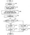
图4为一流程图,其示出了由根据本发明第一实施例的爆燃判定装置中的发动机ECU执行的程序的控制结构;Fig. 4 is a flow chart showing the control structure of a program executed by the engine ECU in the knocking determination device according to the first embodiment of the present invention;
图5示出了正规化后的振动波形;Fig. 5 shows the vibration waveform after normalization;
图6示出了正规化前的振动波形;Figure 6 shows the vibration waveform before normalization;
图7示出了根据本发明第一实施例的爆燃判定装置中将发动机振动波形与爆燃波形模型进行比较的时刻;Fig. 7 shows the moment when the engine vibration waveform is compared with the knock waveform model in the knock determination device according to the first embodiment of the present invention;
图8为一流程图,其示出了由根据本发明第二实施例的爆燃判定装置中的发动机ECU执行的程序的控制结构;FIG. 8 is a flowchart showing a control structure of a program executed by an engine ECU in a knock determination apparatus according to a second embodiment of the present invention;
图9示出了根据本发明第二实施例的爆燃判定装置中将发动机振动波形与爆燃波形模型进行比较的时刻。FIG. 9 shows the timing at which the engine vibration waveform is compared with the knock waveform model in the knock determination device according to the second embodiment of the present invention.
具体实施方式Detailed ways
下面将参照附图以实施例介绍本发明,在下面的介绍中,同样的部件有同样的标注并在名称和功能上相同。因此,不再重复对其进行详细介绍。The present invention will be described with embodiments below with reference to the accompanying drawings. In the following description, the same parts have the same labels and are the same in name and function. Therefore, its detailed introduction will not be repeated.
第一实施例first embodiment
参照图1,将介绍装有根据本发明第一实施例的爆燃判定装置的车辆的发动机100。根据本实施例的爆燃判定装置通过由例如发动机ECU(电子控制单元)200执行的程序实现。Referring to FIG. 1, an
发动机100为内燃机,其使得通过空气净化器102吸入的空气与由喷射器104喷射的燃料的混合物在燃烧室内由火花塞106点火并由此燃烧。The
燃烧的空气-燃料混合物产生燃烧压力,该压力压下活塞108,且曲轴110旋转。燃烧后的空气-燃料混合物(或排气)由三元触媒112净化,随后排出车外。发动机100吸入由节流阀114调节的量的空气。The combusting air-fuel mixture creates combustion pressure that depresses
发动机100由发动机ECU200控制,发动机ECU200连接到爆燃传感器300、水温传感器302、被设置为与定时转子(timing rotor)304相对的曲柄位置传感器306、节流阀开度传感器308、车速传感器310、点火开关312。The
爆燃传感器300由压电元件实现。由于发动机100振动,爆燃传感器300产生电压,该电压具有与振动大小对应的大小。爆燃传感器300向发动机ECU200传送表示该电压的信号。水温传感器302在水冷套处检测发动机100中的冷却水的温度,并向发动机ECU200传送表示检测结果的信号。The
定时转子304被设置在曲轴110上并随着曲轴110的旋转而旋转。定时转子304周围具有如预定间隔的多个突起。曲柄位置传感器306被布置为与定时转子304的凸起相对。当定时转子304旋转时,定时转子304的凸起与曲柄位置传感器306之间的气隙发生变化,曲柄位置传感器306的线圈部分通过增大/减小的磁通,并因此感生电动势。曲柄位置传感器306向发动机ECU200传送表示该电动势的信号。由此信号,发动机ECU200检测曲柄角度。The
节流阀开度传感器308检测节流阀开度并将表示检测结果的信号传送到发动机ECU200。车速传感器310检测车轮(未示出)的转速,并将表示检测结果的信号传送到发动机ECU200。由车轮转速,发动机ECU200计算车速。点火开关312由起动发动机100的驾驶者打开。The
发动机ECU200使用从各传感器以及点火开关312传送来的信号以及存储在存储器202中的图和程序来执行算术运算以控制设备,使得发动机100具有希望的运行状况。
在本实施例中,发动机ECU200依赖于从爆燃传感器300传送的信号和曲柄角度在预定的爆燃检测通道(gate)(从预定的第一曲柄角度到预定的第二曲柄角度的区间)上检测发动机100的振动波形(下面将振动的这种波形简称为“振动波形”),并由检测得到的振动波形判定发动机100是否爆燃。本实施例的爆燃检测通道从燃烧行程中的上死点(0°)到90°。注意,爆燃检测通道不限于此。In the present embodiment, the
为了判定发动机是否爆燃,发动机ECU200的存储器202存储与发动机100爆燃时所产生振动的波形模型对应的爆燃波形模型,如图2所示。In order to determine whether the engine is knocking, the
在该爆燃波形模型中,振动强度用0到1的无量纲数表示,且不与曲柄角度唯一对应。具体而言,对于本实施例的爆燃波形模型,尽管判定为在振动强度峰值后,振动在强度上随着曲柄角度增加而降低,不判定振动强度在其上具有峰值的曲柄角度。另外,爆燃波形模型是各频带振动合成波形。在图2中,CA表示曲柄角度。In the deflagration waveform model, the vibration intensity is represented by a dimensionless number from 0 to 1, and does not uniquely correspond to the crank angle. Specifically, with the knock waveform model of the present embodiment, although it is determined that after the vibration intensity peaks, the vibration decreases in intensity as the crank angle increases, the crank angle at which the vibration intensity has a peak is not determined. In addition, the knock waveform model is a synthetic waveform of vibration in each frequency band. In FIG. 2, CA represents the crank angle.
本实施例的爆燃波形模型对应于爆燃产生的在振动强度峰值后的振动。应当注意,如图3所示,可存储与爆燃引起的在振动上升后的振动对应的爆燃波形模型。The deflagration waveform model of the present embodiment corresponds to the vibration generated by the deflagration after the peak value of the vibration intensity. It should be noted that, as shown in FIG. 3 , a knock waveform model corresponding to the vibration after the vibration rise caused by the knock may be stored.
如下获取爆燃波形模型:进行试验等等以便使发动机100爆燃,从而检测发动机100的振动波形,由该波形创建并预先存储爆燃波形模型。然而,应当注意,可以用不同的方法创建该模型。发动机ECU200将检测波形与存储的爆燃波形模型进行比较以判定发动机100是否爆燃。The knock waveform model is obtained by conducting an experiment or the like to knock the
参照图4,下面将介绍由本实施例的爆燃判定装置中的发动机ECU200执行的程序的控制结构。Referring to FIG. 4, the control structure of the program executed by
在步骤(下面简称为“S”)100中,发动机ECU200由传送自爆燃传感器300的信号检测发动机100的振动强度。振动强度用输出自爆燃传感器300的电压值表示。注意,振动强度可用与输出自爆燃传感器300的电压值对应的值表示。在燃烧行程中对于从上死点到(曲柄角度)90°的角度检测振动强度。In step (hereinafter simply referred to as “S”) 100 ,
在S102中,发动机ECU200对于每5度的曲柄角度计算输出自爆燃传感器300的电压值(即表示振动强度)的积分(下面也称为“积分值”)。对每个频带的振动计算积分值,然后将相应频带的积分值合成在一起。因此,检测到发动机100的振动波形。In S102 ,
在S104中,发动机ECU200在各自移动5度的多个时刻将振动波形与爆燃波形模型进行比较,计算出相关系数K,K是与振动波形及爆燃波形模型之间的偏差有关的值。将振动波形在与爆燃波形模型比较之前进行正规化。这里,对波形进行正规化意味着将各积分值除以在振动波形与爆燃波形模型重叠的曲柄角度上的最大积分值,使得振动强度用0到1的无量纲数字表示,如图5所示。In S104 ,
对于各曲柄角度(5度的)计算在各时刻的正规化振动波形与爆燃波形模型之间的偏差绝对值(或偏移量),以便计算相关系数K。如果正规化振动波形与爆燃波形模型对于每个曲柄角度提供了偏差绝对值ΔS(I)(其中,I为自然数),且用强度表示的爆燃波形模型振动对曲柄角度的积分(即爆燃波形模型的面积)用S表示,则相关系数K用公式K=(S-∑ΔS(I))/S计算,其中,∑ΔS(I)表示对于振动波形与爆燃波形模型重叠的曲柄角度的ΔS(I)的总和。注意,相关系数K可通过不同的方法计算。The absolute value (or offset) of the deviation between the normalized vibration waveform and the knock waveform model at each time point is calculated for each crank angle (of 5 degrees) to calculate the correlation coefficient K. If the normalized vibration waveform and the deflagration waveform model provide the absolute value of the deviation ΔS(I) (wherein, I is a natural number) for each crank angle, and the deflagration waveform model represented by the intensity integral of the vibration to the crank angle (that is, the deflagration waveform model area) is represented by S, and the correlation coefficient K is calculated by the formula K=(S-∑ΔS(I))/S, wherein, ∑ΔS(I) represents the ΔS( I) sum. Note that the correlation coefficient K can be calculated by different methods.
再次参照图4,在S106中,发动机ECU200计算爆燃强度N。爆燃强度N是在以下基础上计算得到的:计算所得相关系数K中的最大值以及最大的积分值P,即在提供最大相关系数K的时刻上的最大积分值。如果发动机100没有爆燃且以用本底水平(background level)(BGL)的值表示的强度振动,于是,通过公式N=P×K/BGL计算爆燃强度N。BGL被存储在存储器202中。注意,爆燃强度N可以用不同的方法计算。Referring again to FIG. 4 ,
在S108中,发动机ECU200判定爆燃强度N是否大于预定基准值。如果大于(步骤S108中的是),控制以S110进行,否则(步骤S108中的否),控制以S114进行。In S108,
在S110中,发动机ECU200判定为发动机100爆燃。在S112中,发动机ECU200引入点火延迟(spark retard)。在S114中,发动机ECU200判定为发动机100没有爆燃。在S116中,发动机ECU200引入点火提前(spark advance)。In S110 ,
将基于上面介绍的结构和流程图对根据本实施例的爆燃判定装置的发动机ECU200的运行进行介绍。The operation of the
当驾驶者打开点火开关312且发动机100起动时,由传送自爆燃传感器300的信号在强度上检测发动机100的振动(S100)。When the driver turns on the
在从上死点到90°的范围的燃烧行程中,对于各频率计算每5度的积分值,并将为各频率计算得到的积分值合成在一起(S102)。因此,如图6所示,检测出发动机100的振动波形。In the combustion stroke ranging from the top dead center to 90°, an integral value every 5 degrees is calculated for each frequency, and the integral values calculated for each frequency are synthesized together (S102). Therefore, as shown in FIG. 6 , the vibration waveform of the
使用每5度的积分值来检测振动波形使得对这样的振动波形的最小化检测成为可能:该波形有着由于具有细微变化的强度的振动引起的复杂形状。这能有助于将检测振动波形与爆燃波形模型进行比较。Detecting a vibration waveform using an integral value every 5 degrees makes it possible to minimize the detection of a vibration waveform having a complicated shape due to vibrations with minutely varying intensities. This can help to compare the detected vibration waveform with a model of the deflagration waveform.
这里,假设对于15°-20°的积分值被计算为由于爆燃引起的振动的强度峰值,而对于50°-55°的积分值被计算为并非由于爆燃引起的振动(噪音)的强度峰值。另外,并非由于爆燃引起的振动的峰值大于由于爆燃引起的振动的强度峰值。Here, it is assumed that the integrated value for 15°-20° is calculated as the intensity peak of vibration due to knocking, and the integrated value for 50°-55° is calculated as the intensity peak of vibration (noise) not due to knocking. In addition, the peak value of the vibration not due to knocking is larger than the intensity peak of the vibration due to knocking.
注意,尽管图6示出了矩形的振动波形,每个积分值可用线连接以表示振动波形。另外,各积分值可单独地用点表示以表示振动波形。Note that although FIG. 6 shows a rectangular vibration waveform, each integrated value may be connected by a line to represent the vibration waveform. In addition, each integral value may be individually represented by a dot to represent a vibration waveform.
如图7所示,在各自移动5度的多个时刻上将检测振动波形与爆燃波形模型(虚线)进行比较。在每个时刻上,为各曲柄角度计算正规化的振动波形与爆燃波形模型的偏差绝对值ΔS(I)。代表对曲柄角度积分的爆燃波形模型振动强度的值S以及这种ΔS(I)的总和∑ΔS(I)用于计算相关系数K=(S-∑ΔS(I))/S(S104)。这使得检测振动波形与爆燃波形模型的匹配程度能被数值地表示,并因此能被客观判定。As shown in FIG. 7 , the detected vibration waveform was compared with the knock waveform model (dotted line) at a plurality of times each shifted by 5 degrees. At each time point, the absolute value ΔS(I) of the deviation of the normalized vibration waveform from the knock waveform model is calculated for each crank angle. The value S representing the vibration intensity of the knock waveform model integrated with the crank angle and the sum ΣΔS(I) of such ΔS(I) are used to calculate the correlation coefficient K=(S-ΣΔS(I))/S (S104). This enables the degree of matching between the detected vibration waveform and the deflagration waveform model to be expressed numerically, and thus can be judged objectively.
尽管在图7中将正规化之前的振动波形与爆燃波形模型(虚线)进行比较,实际上,将正规化的振动波形与爆燃波形模型进行比较。具体而言,通过将每个积分值除以在振动波形与爆燃波形模型重叠的曲柄角度上的最大积分值,将振动波形正规化,且正规化的振动波形与爆燃波形模型之间的比较在以5度移动的各时刻上进行。另外,图7中虚线所示的爆燃波形模型对应于一部分这样的时刻:在其上,进行与振动波形的比较。Although the vibration waveform before normalization is compared with the knock waveform model (broken line) in FIG. 7 , in fact, the normalized vibration waveform is compared with the knock waveform model. Specifically, the vibration waveform was normalized by dividing each integral value by the maximum integral value at the crank angle where the vibration waveform overlapped with the knock waveform model, and the comparison between the normalized vibration waveform and the knock waveform model was in Carried out at each moment of movement by 5 degrees. In addition, the knock waveform model shown by the dotted line in FIG. 7 corresponds to a portion of timing at which comparison with the vibration waveform is made.
通过振动波形的这种正规化,不论各个时刻上的振动强度如何,可用一个爆燃波形模型为所有时刻对振动波形进行分析。这可消除存储与振动强度对应的大量爆燃波形模型的必要性,并因此有助于创建爆燃波形模型。By such normalization of the vibration waveform, the vibration waveform can be analyzed for all times with one deflagration waveform model regardless of the vibration intensity at each time. This can eliminate the need to store a large number of deflagration waveform models corresponding to vibration intensities, and thus facilitates the creation of deflagration waveform models.
在计算得到相关系数K之后,将相关系数K与最大积分值P的乘积除以BGL,以便计算爆燃强度N(S106)。因此,除了在检测振动波形与爆燃波形模型之间的匹配程度以外,还可依赖于振动强度来更加详细地分析发动机100的振动是否是由于爆燃引起的。After the correlation coefficient K is calculated, the product of the correlation coefficient K and the maximum integral value P is divided by BGL to calculate the knock intensity N (S106). Therefore, in addition to detecting the degree of matching between the vibration waveform and the knock waveform model, whether the vibration of the
计算爆燃强度N时使用的相关系数K是计算所得的相关系数K中最大的。也就是说,使用在这样的时刻计算得到的相关系数K计算爆燃强度N:该时刻提供了振动波形与爆燃波形模型之间的最小偏差。The correlation coefficient K used in calculating the knock intensity N is the largest among the calculated correlation coefficients K. That is, the knock intensity N is calculated using the correlation coefficient K calculated at the timing that provides the smallest deviation between the vibration waveform and the knock waveform model.
计算爆燃强度N时使用的最大积分值P是在这样的时刻上的最大积分值:在该时刻上,计算出最大的相关系数K。也就是说,其是提供振动波形与爆燃波形模型间最小偏差的时刻以及振动波形与爆燃波形模型重叠的曲柄角度上的最大积分值。因此,可取决于很有可能是爆燃引起的振动的波形的振动波形以及振动的强度来判定发动机100是否爆燃。The maximum integral value P used in calculating the knock intensity N is the maximum integral value at the time point at which the largest correlation coefficient K is calculated. That is, it is the timing providing the smallest deviation between the vibration waveform and the knock waveform model and the maximum integral value over the crank angle at which the vibration waveform overlaps the knock waveform model. Therefore, whether or not the
这里,假设相关系数K当在对于15°-20°的积分值与爆燃波形模型的振动强度峰值匹配的时刻计算时最大。在该时刻,振动波形与爆燃波形模型在15°-90°的曲柄角度上重叠,因此,为用于计算爆燃强度N的最大积分值P使用了对于50°-55°的积分值。Here, it is assumed that the correlation coefficient K is maximum when calculated at the time when the integrated value for 15°-20° matches the vibration intensity peak value of the knock waveform model. At this moment, the vibration waveform and the knock waveform model overlap over a crank angle of 15°-90°, and therefore, for the maximum integral value P for calculating the knock intensity N, an integral value for 50°-55° is used.
如果计算得到的爆燃强度N大于预定基准值(S108中的是),做出发动机爆燃的判定(S110),并引入点火延迟(S112)以阻止发动机爆燃。If the calculated knock intensity N is greater than the predetermined reference value (YES in S108), a determination of engine knock is made (S110), and an ignition retard is introduced (S112) to prevent engine knock.
如果爆燃强度N不大于预定基准值(S108中的否),做出发动机没有爆燃的判定(S114),并引入点火提前(S116)。If the knock intensity N is not greater than the predetermined reference value (NO in S108), a determination is made that the engine is not knocked (S114), and ignition advance is introduced (S116).
因此,在本实施例的爆燃判定装置中,发动机ECU基于传送自爆燃传感器的信号检测发动机振动波形,并在多个时刻上将该振动波形与爆燃振动模型进行比较以计算相关系数K。计算所得相关系数K中的最大相关系数K——即在振动波形与爆燃波形模型间偏差最小的时刻计算得到的相关系数K——与该时刻的最大积分值P的乘积被除以BGL以计算爆燃强度N。如果爆燃强度N大于基准值,做出发动机发生爆燃的判定。如果爆燃强度N不大于基准值,做出发动机没有爆燃的判定。因此,当除爆燃引起的振动外检测到并非由于爆燃引起的振动时,对各时刻的振动进行分析以判定发动机是否爆燃。这可防止在发动机实际爆燃时错误判定为发动机没有爆燃,这种错误判定可能由仅分析并非由于爆燃引起的振动而引起。因此,可用高精度判定发动机是否爆燃。Therefore, in the knock determination device of this embodiment, the engine ECU detects the engine vibration waveform based on the signal transmitted from the knock sensor, and compares the vibration waveform with the knock vibration model at multiple times to calculate the correlation coefficient K. The product of the maximum correlation coefficient K among the calculated correlation coefficients K—that is, the correlation coefficient K calculated at the moment when the deviation between the vibration waveform and the deflagration waveform model is the smallest—and the maximum integral value P at this moment is divided by BGL to calculate Deflagration intensity N. If the knock intensity N is greater than the reference value, a determination is made that the engine knock occurs. If the knock intensity N is not greater than the reference value, a determination is made that the engine is not knocked. Therefore, when vibration not due to knocking is detected in addition to vibration caused by knocking, the vibration at each time point is analyzed to determine whether the engine is knocking. This prevents an erroneous determination that the engine is not knocking when the engine is actually knocking, which could be caused by analyzing only vibrations not due to knocking. Therefore, whether or not the engine knocks can be determined with high accuracy.
第二实施例second embodiment
参照图8与9,将介绍本发明的第二实施例。在前面的第一实施例中,在以5度移动的多个时刻上将振动波形与爆燃波形模型进行比较。相反,在本实施例中,在振动波形中振动在强度上减小的时刻将振动波形与爆燃波形模型进行比较。其他的配置与前面的第一实施例相同。它们的功能也是同样的。因此,不再重复进行详细介绍。Referring to Figs. 8 and 9, a second embodiment of the present invention will be described. In the foregoing first embodiment, the vibration waveform was compared to the knock waveform model at multiple times shifted by 5 degrees. In contrast, in the present embodiment, the vibration waveform is compared with the knock waveform model at the moment when the vibration decreases in intensity in the vibration waveform. Other configurations are the same as in the previous first embodiment. Their functions are also the same. Therefore, the detailed description will not be repeated.
参照图8,将介绍由根据本实施例的爆燃判定装置的发动机ECU200所执行程序的控制结构。与前面的第一实施例相同的处理用同样的参考步骤标号表示,且不再重复对其进行详细介绍。Referring to FIG. 8 , a control structure of a program executed by
在S200中,发动机ECU200在振动波形中振动强度降低的时刻将振动波形与爆燃波形模型进行比较以计算相关系数K。这里,振动波形在与爆燃波形模型进行比较之前被正规化。In S200 ,
下面基于上述结构介绍根据本实施例的爆燃判定装置的发动机ECU200的运行。The operation of the
当驾驶者打开点火开关312且发动机100起动时,从传送自爆燃传感器300的信号在强度上检测发动机100的振动(S100)。When the driver turns on the
在从上死点到90°的范围的燃烧行程中,为各频率计算每5度的积分值并将为各频率计算得到的积分值合成在一起(S102)。由此,检测得到发动机100的振动波形。In the combustion stroke ranging from the top dead center to 90°, an integral value every 5 degrees is calculated for each frequency and the integrated values calculated for each frequency are combined (S102). Thus, the vibration waveform of the
这里,如同上面的第一实施例一样,假设对于15°-20°的积分值是由于爆燃引起的振动的强度峰值,而对于50°-55°的积分值是并非由于爆燃引起的振动的强度峰值。另外,对于50°-55°的积分值大于对于15°-20°的积分值。Here, as in the first embodiment above, it is assumed that the integrated value for 15°-20° is the peak intensity of vibration due to knocking, and the integrated value for 50°-55° is the intensity of vibration not due to knocking peak. In addition, the integral value for 50°-55° is larger than that for 15°-20°.
如图9所示,在振动波形中振动强度(积分值)减小的时刻将检测得到的振动波形与爆燃波形模型(长短交替的虚线)进行比较。在每个时刻,为各曲柄角度计算正规化的振动波形与爆燃波形模型的偏差绝对值ΔS(I)。表示对曲柄角度积分的爆燃波形模型振动强度的值S以及这种ΔS(I)的总和∑ΔS(I)用于计算相关系数K=(S-∑ΔS(I))/S(S200)。As shown in FIG. 9 , the detected vibration waveform is compared with the knock waveform model (alternating long and short dashed lines) at the moment when the vibration intensity (integrated value) decreases in the vibration waveform. At each moment, the absolute value ΔS(I) of the deviation between the normalized vibration waveform and the knock waveform model is calculated for each crank angle. The value S representing the vibration intensity of the knock waveform model integrated with the crank angle and the sum ΣΔS(I) of such ΔS(I) are used to calculate the correlation coefficient K=(S-ΣΔS(I))/S (S200).
尽管在图9中将正规化之前的振动波形与爆燃波形模型(长短交替虚线)进行比较,实际上如同第一实施例中一样将正规化后的振动波形与爆燃波形模型进行比较。具体而言,通过将每个积分值除以在振动波形与爆燃波形模型重叠的曲柄角度上的最大积分值,对振动波形进行正规化,并将正规化后的振动波形与爆燃波形模型进行比较。Although the vibration waveform before normalization is compared with the knock waveform model (alternating long and short dash lines) in FIG. 9 , the normalized vibration waveform is actually compared with the knock waveform model as in the first embodiment. Specifically, the vibration waveform is normalized by dividing each integral value by the maximum integral value at the crank angle at which the vibration waveform overlaps with the knock waveform model, and the normalized vibration waveform is compared with the knock waveform model .
在计算得到相关系数K之后,将相关系数K与最大积分值P的乘积除以BGL以计算爆燃强度N(S106)。计算爆燃强度N时使用的相关系数K是计算所得相关系数K中最大的。也就是说,使用在提供振动波形与爆燃波形模型间最小偏差的时刻上计算得到的相关系数K计算爆燃强度N。After the correlation coefficient K is calculated, the product of the correlation coefficient K and the maximum integral value P is divided by BGL to calculate the knock intensity N (S106). The correlation coefficient K used when calculating the deflagration intensity N is the largest among the calculated correlation coefficients K. That is, the knock intensity N is calculated using the correlation coefficient K calculated at the time point providing the smallest deviation between the vibration waveform and the knock waveform model.
计算爆燃强度N时使用的最大积分值P是计算得到最大相关系数K的时刻上的最大积分值P。也就是说,其是在提供振动波形与爆燃波形模型间最小偏差的时刻上以及在振动波形与爆燃波形模型重叠的曲轴角度上的最大积分值P。The maximum integral value P used when calculating the knock intensity N is the maximum integral value P at the moment when the maximum correlation coefficient K is calculated. That is, it is the maximum integral value P at the timing providing the smallest deviation between the vibration waveform and the knock waveform model and at the crankshaft angle at which the vibration waveform overlaps with the knock waveform model.
这里,假设相关系数K当在对于15°-20°的积分值与爆燃波形模型的振动强度峰值匹配的时刻上计算时最大。在该时刻上,振动波形与爆燃波形模型在15°-90°的曲柄角度上重叠,因此,为用于计算爆燃强度N的最大积分值P使用了50°-55°的积分值。Here, it is assumed that the correlation coefficient K is maximum when calculated at the time when the integrated value for 15°-20° matches the vibration intensity peak value of the knock waveform model. At this point in time, the vibration waveform and the knock waveform model overlap over a crank angle of 15°-90°, and therefore, an integral value of 50°-55° is used for the maximum integral value P for calculating the knock intensity N.
如果计算得到的爆燃强度N大于预定基准值(S108中的是),做出发动机爆燃的判定(S110),并引入点火延迟(S112)以阻止发动机爆燃。If the calculated knock intensity N is greater than the predetermined reference value (YES in S108), a determination of engine knock is made (S110), and an ignition retard is introduced (S112) to prevent engine knock.
如果爆燃强度N不大于预定基准值(S108中的否),做出发动机没有爆燃的判定(S114),并引入点火提前(S116)。If the knock intensity N is not greater than the predetermined reference value (NO in S108), a determination is made that the engine is not knocked (S114), and ignition advance is introduced (S116).
因此,在本实施例的爆燃判定装置中,发动机ECU基于传送自爆燃传感器的信号检测发动机振动波形,并在振动强度降低的时刻上将振动波形与爆燃振动模型进行比较以计算相关系数K。将计算所得相关系数K中的最大值——即在振动波形与爆燃波形模型间偏差最小的时刻上计算的相关系数K——与该时刻的最大积分值P的乘积除以BGL,以便计算爆燃强度N。如果爆燃强度N大于基准值,做出发动机发生爆燃的判定。如果爆燃强度N不大于基准值,做出发动机没有爆燃的判定。因此,可获得与第一实施例中类似的效果,且用于计算相关系数K的时刻与第一实施例相比可被减少。因此,可以减轻发动机ECU的工作量,并可快速判定发动机是否爆燃。Therefore, in the knock determination device of the present embodiment, the engine ECU detects the engine vibration waveform based on the signal transmitted from the knock sensor, and compares the vibration waveform with the knock vibration model at the time when the vibration intensity decreases to calculate the correlation coefficient K. Divide the product of the maximum value of the calculated correlation coefficient K—that is, the correlation coefficient K calculated at the time when the deviation between the vibration waveform and the deflagration waveform model is the smallest—by the maximum integral value P at this time by BGL to calculate the deflagration Strength N. If the knock intensity N is greater than the reference value, a determination is made that the engine knock occurs. If the knock intensity N is not greater than the reference value, a determination is made that the engine is not knocked. Therefore, similar effects to those in the first embodiment can be obtained, and the timing for calculating the correlation coefficient K can be reduced compared with the first embodiment. Therefore, the workload of the engine ECU can be reduced, and whether the engine is knocked can be quickly determined.
应当明了,这里公开的实施例是说明性而不是限制性的。本发明的范围由权利要求书的条款而不是上面的介绍和实例限定,并包括属于权利要求书条款的范围或等同含义的所有修改和改变。It should be understood that the embodiments disclosed herein are illustrative rather than restrictive. The scope of the present invention is defined by the terms of the claims, rather than the above description and examples, and includes all modifications and changes falling within the scope of the terms of the claims or equivalent meanings.
Claims (4)
Translated fromChineseApplications Claiming Priority (3)
| Application Number | Priority Date | Filing Date | Title |
|---|---|---|---|
| JP2004371898AJP2006177259A (en) | 2004-12-22 | 2004-12-22 | Internal combustion engine knock determination device |
| JP371898/2004 | 2004-12-22 | ||
| PCT/JP2005/023841WO2006068280A1 (en) | 2004-12-22 | 2005-12-20 | Knock determination device for internal combustion engine |
Publications (2)
| Publication Number | Publication Date |
|---|---|
| CN101084423A CN101084423A (en) | 2007-12-05 |
| CN101084423Btrue CN101084423B (en) | 2012-05-02 |
Family
ID=36069263
Family Applications (1)
| Application Number | Title | Priority Date | Filing Date |
|---|---|---|---|
| CN2005800440759AActiveCN101084423B (en) | 2004-12-22 | 2005-12-20 | Knock Deflagration Determination Device for Internal Combustion Engine |
Country Status (6)
| Country | Link |
|---|---|
| US (1) | US7251556B2 (en) |
| EP (1) | EP1848974B1 (en) |
| JP (1) | JP2006177259A (en) |
| CN (1) | CN101084423B (en) |
| DE (1) | DE602005020191D1 (en) |
| WO (1) | WO2006068280A1 (en) |
Families Citing this family (17)
| Publication number | Priority date | Publication date | Assignee | Title |
|---|---|---|---|---|
| JP2006177259A (en)* | 2004-12-22 | 2006-07-06 | Toyota Motor Corp | Internal combustion engine knock determination device |
| JP4342520B2 (en)* | 2006-01-27 | 2009-10-14 | トヨタ自動車株式会社 | Ignition timing control device for internal combustion engine |
| JP4312213B2 (en)* | 2006-06-28 | 2009-08-12 | トヨタ自動車株式会社 | Internal combustion engine knock determination device |
| JP4597167B2 (en)* | 2006-06-28 | 2010-12-15 | トヨタ自動車株式会社 | Internal combustion engine knock determination device |
| WO2008014265A2 (en)* | 2006-07-24 | 2008-01-31 | Ethanol Boosting Systems, Llc | Single nozzle direct injection system for rapidly variable gasoline/anti-knock agent mixtures |
| US7703446B2 (en)* | 2006-07-24 | 2010-04-27 | Ethanol Boosting Systems Llc | Single nozzle direct injection system for rapidly variable gasoline/anti-knock agents mixtures |
| JP4490455B2 (en) | 2006-10-06 | 2010-06-23 | トヨタ自動車株式会社 | Internal combustion engine knock determination device, knock determination method, program for realizing the method, and recording medium storing the program |
| JP4600431B2 (en) | 2007-05-30 | 2010-12-15 | トヨタ自動車株式会社 | Internal combustion engine knock determination device |
| KR100993378B1 (en)* | 2008-12-03 | 2010-11-09 | 서울대학교산학협력단 | Method and apparatus for judging combustion time of compression ignition engine |
| JP5464202B2 (en) | 2011-12-12 | 2014-04-09 | 株式会社デンソー | Electronic control device for internal combustion engine |
| KR101316281B1 (en)* | 2011-12-13 | 2013-10-08 | 아주대학교산학협력단 | Method for controlling of combustion in diesel engine |
| CN103758641B (en)* | 2014-01-14 | 2016-02-10 | 上海交通大学 | A kind of Engine Knock comprising external exhaust gas recirculation impact judges and the Forecasting Methodology in moment occurs |
| US9752949B2 (en)* | 2014-12-31 | 2017-09-05 | General Electric Company | System and method for locating engine noise |
| JP6312618B2 (en)* | 2015-03-13 | 2018-04-18 | 日立オートモティブシステムズ株式会社 | Internal combustion engine control device and abnormal combustion detection method |
| US10371079B2 (en)* | 2016-09-09 | 2019-08-06 | Ford Global Technologies, Llc | Method and system for knock sensor rationality check |
| CN110940528B (en)* | 2019-12-19 | 2022-04-19 | 中国人民解放军海军士官学校 | Method and system for identifying working modal parameters of diesel engine based on detonation excitation |
| CN116337327B (en)* | 2023-03-24 | 2025-09-19 | 潍柴动力股份有限公司 | Tamper detection method and device for knock sensor, electronic device and storage medium |
Family Cites Families (23)
| Publication number | Priority date | Publication date | Assignee | Title |
|---|---|---|---|---|
| JPS631761A (en) | 1986-06-19 | 1988-01-06 | Nissan Motor Co Ltd | Internal combustion engine ignition timing control device |
| GB2245382B (en) | 1990-04-28 | 1994-03-23 | Motorola Inc | Automotive diagnostic system |
| JPH0819890B2 (en) | 1990-07-16 | 1996-03-04 | 株式会社ユニシアジェックス | Knocking detection device and ignition timing correction device for internal combustion engine |
| JP3325067B2 (en) | 1993-02-26 | 2002-09-17 | 株式会社日立製作所 | Knock detection device for internal combustion engine |
| FR2731794B1 (en)* | 1995-03-15 | 1997-06-06 | Magneti Marelli France | METHOD AND DEVICE FOR RECOGNIZING SIGNALS OF ON-BOARD VIBRATION SENSORS, IN PARTICULAR FOR RECOGNIZING CLICK OF AN INTERNAL COMBUSTION ENGINE |
| FR2765623B1 (en) | 1997-07-03 | 1999-09-10 | Renault | DEVICE FOR DETECTION AND MEASUREMENT OF CLICK AND ANTICTICTICAL SYSTEM COMPRISING SUCH A DEVICE |
| JP2000205098A (en) | 1999-01-19 | 2000-07-25 | Ngk Spark Plug Co Ltd | Energization control unit for glow plug |
| JP4390939B2 (en) | 1999-12-16 | 2009-12-24 | 株式会社デンソー | Knock control device for internal combustion engine |
| JP3753583B2 (en) | 2000-02-15 | 2006-03-08 | 株式会社デンソー | Knock control device for internal combustion engine |
| US6546328B1 (en)* | 2001-01-03 | 2003-04-08 | Eaton Corporation | Knock and misfire detection system |
| JP4465928B2 (en) | 2001-07-04 | 2010-05-26 | 株式会社デンソー | Knock control device for internal combustion engine |
| JP2002357156A (en) | 2001-05-30 | 2002-12-13 | Mitsubishi Electric Corp | Knock control device for internal combustion engine |
| JP2003172196A (en) | 2001-12-06 | 2003-06-20 | Toyota Motor Corp | Knock control device for internal combustion engine |
| JP2003278592A (en) | 2002-03-22 | 2003-10-02 | Toyota Motor Corp | Knock control device for internal combustion engine |
| DE10215959A1 (en)* | 2002-04-11 | 2003-10-30 | Univ Karlsruhe Th Inst Fuer Ko | Knocking detection method for a petrol-driven external combustion engine, is based on monitoring the cylinder pressure and detection of the high frequency pressure variations associated with knocking |
| DE10300204A1 (en)* | 2003-01-08 | 2004-07-22 | Robert Bosch Gmbh | Knock detection method and apparatus |
| US20040162668A1 (en)* | 2003-02-14 | 2004-08-19 | Stephen Rawlinson | Method of detecting knock in an internal combustion engine |
| JP4297734B2 (en) | 2003-05-28 | 2009-07-15 | 株式会社デンソー | Knock control device for internal combustion engine |
| JP2006177259A (en)* | 2004-12-22 | 2006-07-06 | Toyota Motor Corp | Internal combustion engine knock determination device |
| JP2006226967A (en)* | 2005-02-21 | 2006-08-31 | Toyota Motor Corp | Internal combustion engine knock determination device |
| JP4549920B2 (en)* | 2005-04-27 | 2010-09-22 | トヨタ自動車株式会社 | Internal combustion engine knock determination device |
| JP4538383B2 (en)* | 2005-06-28 | 2010-09-08 | トヨタ自動車株式会社 | Ignition timing control device for internal combustion engine |
| JP4404813B2 (en)* | 2005-06-30 | 2010-01-27 | トヨタ自動車株式会社 | Internal combustion engine knock determination device |
- 2004
- 2004-12-22JPJP2004371898Apatent/JP2006177259A/enactivePending
- 2005
- 2005-12-20DEDE602005020191Tpatent/DE602005020191D1/enactiveActive
- 2005-12-20WOPCT/JP2005/023841patent/WO2006068280A1/enactiveApplication Filing
- 2005-12-20CNCN2005800440759Apatent/CN101084423B/enactiveActive
- 2005-12-20EPEP05842253Apatent/EP1848974B1/enactiveActive
- 2005-12-21USUS11/312,735patent/US7251556B2/enactiveActive
Also Published As
| Publication number | Publication date |
|---|---|
| US7251556B2 (en) | 2007-07-31 |
| EP1848974A1 (en) | 2007-10-31 |
| US20060136117A1 (en) | 2006-06-22 |
| DE602005020191D1 (en) | 2010-05-06 |
| JP2006177259A (en) | 2006-07-06 |
| WO2006068280A1 (en) | 2006-06-29 |
| CN101084423A (en) | 2007-12-05 |
| EP1848974B1 (en) | 2010-03-24 |
Similar Documents
| Publication | Publication Date | Title |
|---|---|---|
| CN101084423B (en) | Knock Deflagration Determination Device for Internal Combustion Engine | |
| US7669459B2 (en) | Knocking determination device for internal combustion engine | |
| CN101184980B (en) | Internal combustion engine knock determination device | |
| US7412874B2 (en) | Internal combustion engine knock determination device | |
| US7945379B2 (en) | Knock determination device and method for internal combustion engine | |
| CN101321946B (en) | Apparatus and method for controlling ignition timing of internal combustion engine | |
| EP1896815B1 (en) | Knocking determination device for internal combustion engine | |
| US7206691B2 (en) | Internal combustion engine knock determination device | |
| US20060236753A1 (en) | Internal combustion engine knock determination device | |
| JP5253432B2 (en) | Internal combustion engine knock determination device | |
| JP2006307665A (en) | Internal combustion engine knock determination device |
Legal Events
| Date | Code | Title | Description |
|---|---|---|---|
| C06 | Publication | ||
| PB01 | Publication | ||
| C10 | Entry into substantive examination | ||
| SE01 | Entry into force of request for substantive examination | ||
| C14 | Grant of patent or utility model | ||
| GR01 | Patent grant |