CN101081563A - Ink tank cartridge for a printer - Google Patents
Ink tank cartridge for a printerDownload PDFInfo
- Publication number
- CN101081563A CN101081563ACN 200610094488CN200610094488ACN101081563ACN 101081563 ACN101081563 ACN 101081563ACN 200610094488CN200610094488CN 200610094488CN 200610094488 ACN200610094488 ACN 200610094488ACN 101081563 ACN101081563 ACN 101081563A
- Authority
- CN
- China
- Prior art keywords
- ink
- ink supply
- chamber
- cartridge
- supply port
- Prior art date
- Legal status (The legal status is an assumption and is not a legal conclusion. Google has not performed a legal analysis and makes no representation as to the accuracy of the status listed.)
- Granted
Links
- 238000007789sealingMethods0.000claimsdescription16
- 239000000976inkSubstances0.000description354
- 239000006260foamSubstances0.000description29
- 238000004891communicationMethods0.000description27
- 239000006261foam materialSubstances0.000description27
- 238000005192partitionMethods0.000description17
- 239000012530fluidSubstances0.000description10
- 239000003086colorantSubstances0.000description8
- 238000000034methodMethods0.000description6
- 238000009434installationMethods0.000description4
- 239000007788liquidSubstances0.000description4
- 230000007423decreaseEffects0.000description2
- 238000010586diagramMethods0.000description2
- 230000000694effectsEffects0.000description2
- 239000002699waste materialSubstances0.000description2
- 239000006096absorbing agentSubstances0.000description1
- 230000002411adverseEffects0.000description1
- 230000007547defectEffects0.000description1
- 238000006073displacement reactionMethods0.000description1
- 238000001035dryingMethods0.000description1
- 239000013013elastic materialSubstances0.000description1
- 230000007613environmental effectEffects0.000description1
- 238000001704evaporationMethods0.000description1
- 239000010408filmSubstances0.000description1
- 238000010438heat treatmentMethods0.000description1
- 238000012856packingMethods0.000description1
- 230000000149penetrating effectEffects0.000description1
- 230000002093peripheral effectEffects0.000description1
- 239000011148porous materialSubstances0.000description1
- 239000010409thin filmSubstances0.000description1
Images


Landscapes
- Ink Jet (AREA)
Abstract
Translated fromChineseDescription
Translated fromChinese技术领域technical field
本发明一般地涉及一种由供墨槽供墨的供墨打印机,尤其涉及一种可向打印头连续供墨同时能避免因温度、气压变化或波动而产生的不利影响的供墨槽。本发明的供墨槽可盛装较大量的油墨,槽中可向打印状输送的油墨的百分比较大。本发明还包括一种具有透明侧壁的墨槽,因此用户易于确定槽中所留油墨的量;本发明还包括不希望使供墨盒中的油墨移动的阻尼装置。The present invention generally relates to an ink supply printer supplied with ink from an ink supply tank, and more particularly to an ink supply tank capable of continuously supplying ink to a printing head while avoiding adverse effects caused by changes or fluctuations in temperature and air pressure. The ink supply tank of the present invention can contain a relatively large amount of ink, and the percentage of the ink that can be transported to the printing shape in the tank is relatively large. The invention also includes an ink tank having transparent side walls so the user can easily determine the amount of ink remaining in the tank; and dampening means that do not wish to dislodge ink in the ink supply cartridge.
本发明还涉及一种喷墨打印机用的墨盒,在这种打印机中,一个喷墨记录头和一个墨盒装在一个可移动的滑动架上,具体地说,在旧墨盒中的油墨用尽了时,就用一个新墨盒更换它。The present invention also relates to an ink cartridge for an ink-jet printer, in which an ink-jet recording head and an ink cartridge are mounted on a movable carriage, in particular, when the ink in the used ink cartridge is exhausted , replace it with a new toner cartridge.
背景技术Background technique
在欧洲专利No 581,531中公开一种现有技术的喷墨打印机,在这种打印机中,盛墨装置和喷墨记录头安装在一个滑动架上。在已公开的这种打印机中,为了防止由于滑动架的移动而引起的墨盒的移动,由随之产生的油墨液位的波动或气泡而造成的打印缺陷,将墨盒分隔成两个区域。墨盒的第一区域邻近记录头,它容纳渗入到一个多孔件中的油墨,第二区域容纳液态油墨,没有多孔件。这种结构使油墨经多孔件输送到记录头,因此,由墨盒中的油墨的移动而引起的问题在某种程度上可避免发生。A prior art inkjet printer is disclosed in European Patent No 581,531. In this printer, an ink holding device and an inkjet recording head are mounted on a carriage. In the disclosed printer, the ink cartridge is divided into two regions in order to prevent the movement of the ink cartridge due to the movement of the carriage, and printing defects caused by the consequent fluctuation of the ink level or air bubbles. A first region of the cartridge, adjacent to the recording head, contains ink that has penetrated a porous member, and a second region contains liquid ink, without the porous member. This structure allows the ink to be delivered to the recording head through the porous member, and therefore, the problems caused by the movement of the ink in the ink cartridge can be avoided to some extent.
多孔件被一个凸出件固定,而与记录头保持流体连通,该凸出件插入在墨盒的侧壁上所形成的孔中。然而,这样的结构不能应用在必须制止气泡进入压力室的记录头的场合中,例如,将压电振动器作为喷墨致动器的喷墨打印机。The porous member is held in fluid communication with the recording head by a protruding member which is inserted into a hole formed in the side wall of the cartridge. However, such a structure cannot be applied to a recording head in which air bubbles must be prevented from entering a pressure chamber, for example, an inkjet printer using a piezoelectric vibrator as an inkjet actuator.
因此产生出解决上述问题的喷墨打印机。Therefore, an inkjet printer that solves the above-mentioned problems has been produced.
发明内容Contents of the invention
一般地说,按照本发明,提供一种供墨打印机。通过包括一个具有一供墨器的墨槽和一对侧壁的供墨系统向打印头供给油墨。在墨槽内有一个油墨吸收件,它位于供墨口附近,所占的空间比墨槽的总容积小。供墨槽的壁是透明的,这样,用户可较容易地确定留在供墨槽中的油墨的量。Generally speaking, in accordance with the present invention, an ink fed printer is provided. Ink is supplied to the printhead by an ink supply system including an ink tank having an ink supply and a pair of side walls. There is an ink absorber inside the ink tank, which is located near the ink supply port and takes up less space than the total volume of the ink tank. The walls of the ink feed slot are transparent so that the user can more easily determine the amount of ink remaining in the ink feed slot.
其一端位于供墨口内的油墨接受和输送件伸入到供墨槽内,在这种情况下,油墨吸收件靠在油墨接收和输送件上,且局部被压缩。油墨接收和输送件具有与打印头流体连通的细长的油墨通道,从油墨吸收件向打印头供给油墨。The ink receiving and delivering member having one end in the ink supply port projects into the ink supply channel, in which case the ink absorbing member abuts against the ink receiving and delivering member and is partially compressed. The ink receiving and delivering member has an elongated ink channel in fluid communication with the printhead to supply ink from the ink absorbing member to the printhead.
具体地说,供墨盒具有储存油墨的墨室和接收吸收油墨的多孔件的泡沫材料室。一块隔板将油墨室和泡沫材料室隔开,该隔板上有一个孔,以使油墨室与泡沫材料室流体连通。该油墨盒上也有一个供墨口。一个漏斗形的密封件装在供墨口内,并借助通过多孔件产生的压差将油墨供给一个记录头。密封件的供墨口内面向上,它是有弹性的。Specifically, the ink supply cartridge has an ink chamber for storing ink and a foam material chamber for receiving an ink-absorbing porous member. A partition separates the ink chamber from the foam chamber, the partition having an aperture to allow fluid communication between the ink chamber and the foam chamber. The ink cartridge also has an ink supply port. A funnel-shaped sealing member is accommodated in the ink supply port, and ink is supplied to a recording head by a pressure difference generated through the porous member. The inside of the seal with the ink supply port facing up is elastic.
当记录头的供墨针状体插入供墨口内时,针状体的顶部与密封件弹性地接触。由于密封件是漏斗状的,开口向上,所以它易于变形,贴紧供墨针。而且,由于它具有弹性,与针状体贴的更紧。这样,可适应供墨针状体和供墨口之间的相对安装误差。这样供墨口可被可靠地密封。When the ink supply needle of the recording head is inserted into the ink supply port, the top of the needle comes into elastic contact with the sealing member. Since the seal is funnel-shaped and opens upward, it is easily deformed to fit tightly against the ink supply needle. And, since it's elastic, it fits tighter with the needles. In this way, relative installation errors between the ink supply needle and the ink supply port can be accommodated. Thus the ink supply port can be reliably sealed.
因此,本发明的目的是提供一种喷墨打印机用的改进的墨盒。SUMMARY OF THE INVENTION It is therefore an object of the present invention to provide an improved ink cartridge for use in ink jet printers.
本发明的一个目的是提供一种结构简单的高质量和高可靠性的供墨打印机,它能将稳定和适当量的油墨从供墨槽供给打印头,而较少受环境变化如温度和压力波动所造成的影响。An object of the present invention is to provide a high-quality and high-reliability ink-supply printer with a simple structure, which can supply a stable and appropriate amount of ink from the ink-supply tank to the print head, and is less affected by environmental changes such as temperature and pressure. the impact of fluctuations.
本发明的另一个目的是提供一种喷墨打印机用的墨盒,安装该盒时用的力最小,供墨针状体的安装误差的充差大,与记录头配合可获得完全的密封,同时形成尽可能小的无用空间。Another object of the present invention is to provide an ink cartridge for an ink-jet printer. The force used when installing the cartridge is the smallest, the installation error of the ink supply needle has a large difference, and it can be completely sealed by cooperating with the recording head. Create as little dead space as possible.
本发明的又一个目的是防止气泡进入记录头,同时在装有多孔件的室中保持负压。Yet another object of the present invention is to prevent air bubbles from entering the recording head while maintaining a negative pressure in the chamber provided with the porous member.
本发明提供一种喷墨式记录设备用的墨盒,包括:The invention provides an ink cartridge for an inkjet recording device, comprising:
在所述墨盒中形成至少一个室的多个壁;a plurality of walls forming at least one chamber in the cartridge;
一个供墨口延伸穿过所述至少一个室的至少一个壁,以便允许油墨通过所述至少一个室流出;和an ink supply port extending through at least one wall of the at least one chamber to allow ink to flow out through the at least one chamber; and
在所述供墨口内安装一个漏斗形密封件,所述密封件具有:一个宽的端部,其尺寸足于接合所述供墨口;一个窄的端部,其尺寸小于所述供墨口;和一个通孔,其穿过所述漏斗形密封件,所述通孔具有一个宽的端部和一个窄的端部,所述通孔的宽的端部的尺寸大于所述供墨针状体的尺寸,所述通孔的窄的端部的尺寸足于接纳喷墨式记录设备的供墨针状体,并弹性地紧靠在所述供墨针状体的外周界面上,所述供墨针状体插入所述供墨口时,所述漏斗形密封件容许油墨只从所述供墨口流动到所述供墨针状体。Mounted within the ink supply port is a funnel-shaped seal having a wide end sized to engage the ink supply port and a narrow end smaller than the ink supply port and a through hole passing through the funnel-shaped seal, the through hole having a wide end and a narrow end, the wide end of the through hole being larger in size than the ink supply needle The size of the shape, the size of the narrow end of the through hole is sufficient to receive the ink supply needle of the inkjet recording device, and elastically close to the outer peripheral interface of the ink supply needle, so The funnel-shaped seal allows ink to flow only from the ink supply port to the ink supply needle when the ink supply needle is inserted into the ink supply port.
由于参照附图所作的如下描述,本发明的其它目的,特征和优点将就得更加明显,其中,图示的实例表示本发明的优选实施例,但不能理解为它们是对本发明的限制。Other objects, features and advantages of the present invention will become more apparent from the following description made with reference to the accompanying drawings, wherein the illustrated examples represent preferred embodiments of the present invention, but they are not to be construed as limiting the invention.
因此,本发明包括若干步骤和这些步骤中的一个或多个与其它每个步骤的关系;还包括体现结构、零件的组合和部件的装配的技术特征的设备,用它们实现那些步骤;还包括在下面详细公开中举例说明的内容,而本发明的保护范围将在权利要求书中表示。Therefore, the present invention includes a number of steps and the relationship of one or more of these steps to each of the other steps; also includes the technical characteristics of the structure, the combination of parts and the assembly of parts, and implements those steps; also includes What is exemplified in the following detailed disclosure, the scope of protection of the invention will be indicated in the claims.
为了充分地理解本发明,结合附图参见下面的描述,其中:For a full understanding of the present invention, reference is made to the following description taken in conjunction with the accompanying drawings, in which:
附图说明Description of drawings
图1是表示本发明的一个实施例的喷墨型记录设备的供墨系统的示意图;1 is a schematic diagram showing an ink supply system of an ink jet type recording apparatus according to an embodiment of the present invention;
图2是按照本发明的第一个实施例构成的多色喷墨打印机墨盒的剖视图;Fig. 2 is the cross-sectional view of the multi-color inkjet printer ink box that the first embodiment of the present invention is formed;
图3是第一实施例从图2的方向旋转90°的剖视图;Fig. 3 is a cross-sectional view of the first embodiment rotated 90° from the direction of Fig. 2;
图4是表示图2和图3的墨盒被拆下了盖后的透视图;Figure 4 is a perspective view showing the ink cartridge of Figures 2 and 3 with the cover removed;
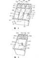
图5是表示按照本发明的第二个实施例构成的单色墨盒的透视图;Figure 5 is a perspective view showing a monochrome ink cartridge constructed according to a second embodiment of the present invention;
图6(a)是图2的多色墨盒的盖的俯视图;Fig. 6 (a) is the top view of the lid of the multi-color ink cartridge of Fig. 2;
图6(b)是表示其上具有附加的密封的盖的俯视图;Figure 6(b) is a top view showing the lid with an additional seal thereon;
图7(a)是表示本发明的其内插有供墨针状体的密封件的剖视图;Fig. 7 (a) is the cross-sectional view showing the sealing member of the present invention in which the ink supply needle is inserted;
图7(b)是供墨针状体插入前的密封件的剖面图;Figure 7 (b) is a cross-sectional view of the seal before the ink supply needle is inserted;
图8是表示油墨消耗,压力值和留在油墨室中的油墨量的之间的关系曲线图;Fig. 8 is a graph showing the relationship between ink consumption, pressure value and the amount of ink remaining in the ink chamber;
图9是本发明的第三个实施例的墨盒的局部剖视图,它表示油墨室和泡沫材料室之间的界面;Figure 9 is a partial sectional view of the ink cartridge of the third embodiment of the present invention, which shows the interface between the ink chamber and the foam material chamber;
图10是本发明的第四个实施例的墨盒的局部剖视图,它表示油墨室和泡沫材料室之间的界面;Figure 10 is a partial sectional view of the ink cartridge of the fourth embodiment of the present invention, which shows the interface between the ink chamber and the foam material chamber;
图11是按照本发明的第五个实施例构成的墨盒的油墨室和泡沫材料室之间的界面的局部剖视图;Fig. 11 is a partial cross-sectional view of the interface between the ink chamber and the foam material chamber of the ink cartridge formed according to the fifth embodiment of the present invention;
图12是沿图11中的33-33线剖切的剖视图;Fig. 12 is a sectional view cut along line 33-33 in Fig. 11;
图13是表示按照本发明的第六个实施例构成的墨盒的油墨盒和泡沫材料室之间的界面的局部剖视图;Fig. 13 is a partial sectional view showing the interface between the ink cartridge and the foam material chamber of the ink cartridge constructed according to the sixth embodiment of the present invention;
图14是沿图13中的35-35线剖切的剖视图;Fig. 14 is a sectional view cut along line 35-35 in Fig. 13;
图15是表示按照本发明的第七个实施例构成的墨盒的剖视图;Fig. 15 is a sectional view showing an ink cartridge constructed according to a seventh embodiment of the present invention;
图16是表示按照本发明的第八个实施例构成的墨盒的剖视图;Fig. 16 is a sectional view showing an ink cartridge constructed according to an eighth embodiment of the present invention;
图17是按照本发明的第九个实施例构成的喷墨打印机用的墨盒的剖视图;Fig. 17 is a sectional view of an ink cartridge for an ink jet printer according to a ninth embodiment of the present invention;
图18是本发明的第九个实施例的墨盒从图17的方向旋转90°的剖视图;Fig. 18 is the sectional view of the ink cartridge of the ninth embodiment of the present invention rotated 90° from the direction of Fig. 17;
具体实施方式Detailed ways
本发明的打印机头可用于四色打印机绘图器或采色图象打印机,它具有四色油墨系统和相应于四种油墨颜色的油墨喷嘴。四色打印机绘图器采用墨色、红色、绿色和兰色油墨,移动打印头或打印纸页,或两者都移动,同时,相应于所需要的一种颜色,对着打印纸在规定的位置象传统的喷墨打印头那样喷射油墨,形成墨点。重复上述循环,使可记录所需的字符和图像。本发明可用于各种喷墨打印机,包括利用加热电阻等产生的热或压电位移或换能器,根据所输入的打印信号,将油墨室的油墨喷射成墨滴的打印头。本发明的供墨槽能使油墨通过细长的通道连续地供给所说的油墨室。The printer head of the present invention can be used in a four-color printer plotter or a color image printer, which has a four-color ink system and ink nozzles corresponding to four ink colors. Four-color printer plotters use black, red, green and blue inks to move the print head or the printed paper, or both, and at the same time, corresponding to a required color, face the printed paper at the specified position as Ink is ejected like a conventional inkjet print head to form ink dots. The above cycle is repeated so that desired characters and images can be recorded. The present invention can be used in various inkjet printers, including printheads that use thermal or piezoelectric displacements generated by heating resistors or transducers to eject ink from ink chambers into ink droplets according to input printing signals. The ink supply channel of the present invention enables ink to be continuously supplied to said ink chamber through the elongated channel.
在利用四种颜色即墨色、红色、绿色和兰色的油墨的采色图像打印机中,打印头在与打印纸的进给方向垂直的方向扫描打印纸页,在一次扫描行程中形成一排点,打印纸向前进给一排点的间距,以记录图像。在七色打印机中,使用四色油墨,即墨色、黄色、品红色和青色,通过叠印墨色以外的三种所需颜色中的两种颜色,在打印纸页上形成 红色、绿色和兰色,所以可记录七种颜色的彩色图像。In a color image printer using inks of four colors, namely ink, red, green and blue, the printing head scans the printing paper in a direction perpendicular to the feeding direction of the printing paper, forming a row of dots in one scanning stroke. , the printing paper advances to the pitch of a row of dots to record the image. In a seven-color printer, four-color inks, namely ink, yellow, magenta, and cyan, are used to form red, green, and blue on a printed page by overprinting two of the three required colors other than ink, so Color images in seven colors can be recorded.
本发明主要涉及打印机头,尤其涉及供墨槽,整个打印机的结构的详细描述将只由一个实例给出。The present invention relates mainly to the printer head, and particularly to the ink supply tank, and a detailed description of the structure of the entire printer will be given by way of example only.
图1是表示本发明的一个实施例的喷墨式记录设备的供墨系统的示意图。FIG. 1 is a schematic diagram showing an ink supply system of an ink jet recording apparatus according to an embodiment of the present invention.
喷墨式打印机的打印组件1通过连接件2与油墨槽3相连。通过中空的针状体和连接件2的供墨通道2b将油墨从油墨槽3供给打印头组件1,因此,打印头组件1根据打印信号喷射油墨滴。A
图1所示的设备还包括一个装在非打印区的帽盖4,一个驱动机构(未示出)将帽盖4压靠在打印头组件1的喷嘴板上,防止喷嘴孔口干燥。帽盖4通过管8与真空泵5连通,控制装置6操作真空泵5,以便通过帽盖4从打印头组件1抽吸油墨。图1所示的装置还包括一个通过管9与真空泵5的出口相连的废油墨槽7。The device shown in FIG. 1 also includes a cap 4 mounted on the non-printing area, and a driving mechanism (not shown) presses the cap 4 against the nozzle plate of the
记录头可以是例如在欧洲专利出版物No.581,531,No.609,863,No.584,823等等中所描述的任何一种结构。The recording head may be of any structure described, for example, in European Patent Publication No. 581,531, No. 609,863, No. 584,823 and the like.
墨盒的形状应使其用较小的力就能进行安装,并可适应一定程度的安装误差。首先参见图2和图3,它们表示按照本发明的第一个实施例所构成的墨盒。图3所示的隔板502和503将盒501隔成三个室504、505和506。中部隔板510将三个室504、505,506的每一个都隔成用于盛装相应的多孔件520、520′或520″的泡沫材料室511、511′或511″和用于盛装液体油墨的油墨室512、512′或512″。泡沫材料室511、511′或511″的大小要能容纳相应的多孔材料520、520′或520″。The shape of the ink cartridge should be such that it can be installed with low force and can accommodate a certain degree of installation error. Referring first to Figures 2 and 3, they show an ink cartridge constructed in accordance with a first embodiment of the present invention.
确定每个多孔件520、520′和520″的体积,要使其大于每个泡沫材料室511、511′或511″的容积,以便在一个优选的实施例中被保持在相应的泡沫材料室内的多孔件会被压缩。确定每个泡沫材料511、511′或511″与每个油墨室512,512′或512″的容积的比,要使每个泡沫材料室511,511′或511″的大小能盛装比相应的油墨室512,512′或512″多20%至30%的油墨。The volume of each
当将三种颜色的油墨装在图2至图4中所示的一个盒内时,难于查看由不同颜色油墨的不平稳消耗所引起的留在室中的油墨量的不同。当一种颜色的油墨被用尽时,用户想要处理这个墨盒,他不必多余地担心留在盒中的其它颜色的墨水会泄漏。在处理本发明的墨盒时,可防止油墨从盒中流出,因为每种颜色的油墨都被每个相应的多孔件吸收,从而可保护四周不泄油墨。When three colors of ink are housed in one cartridge as shown in FIGS. 2 to 4, it is difficult to see the difference in the amount of ink remaining in the chamber caused by uneven consumption of inks of different colors. When the ink of one color is used up, the user wants to dispose of this ink cartridge without unnecessarily worrying that the ink of other colors remaining in the cartridge will leak. When handling the ink cartridge of the present invention, ink can be prevented from flowing out of the cartridge because ink of each color is absorbed by each corresponding porous member, thereby protecting the surroundings from ink leakage.
在盒501的各自的泡沫材料室511,511′和511″内形成供墨口513,513′和513″(未示出)。室511是每个室511,511′和511″中的一个例子。每个供墨口513,513′和513″都适于与记录头的相应的供墨针状体配合,供墨针状体在每个泡沫材料室511,511′和511″的下端插入。
现参见图2和图3,盖516将盒501的上端密封。在盖516相应于泡沫材料室511的位置形成两个装墨口514、515。类似地,在图6(a)中,每个室511,511′和511″都包括相应的装置墨口514和515,514′和515以及514″和515″。图2所示的凸出部516a和516b与盖516的下表面形成一体并位于泡沫材料室511内,以便分别围绕着装墨口515和514。凸出部516a和516b将多孔件520向着泡沫材料室511的底壁压缩,供墨口513就形成在底壁上。凸出部516a′和516b′以及516a″和516b″类似地形成在盖516的内壁上,位于泡沫材料室511′和511″内,如图3所示,它们分别具有供墨口513′和513″。Referring now to FIGS. 2 and 3 , the
与供墨口513相对的凸出部516a的下顶端比凸出部516b的下顶端的位置低,从而,在供墨口513的附近的那部分多孔件压缩程度最大。The lower top end of the
在每个泡沫材料室511,511′和511″的底上分别形成隆起部522,522′和522″(总起来称为522),它们和盖516共同压缩多孔件520,520′和520″。在相应的隆起部522的上端形成凹口523,523′和523″(总起来称为523),它们限定具有一个固定开口区域的空间。在相应的隆起部522内形成通孔524,524′和524″(总起来称为524)。每个通孔524的一端与由凹口523限定的空间呈流体连通,另一端下面将要进行描述的一个相应的密封件(总起来称为530)连通。过滤器525,525′和525″(未示出)(总起来称为525)被分别固定在凹口523的上端。On the bottom of each
只示出一个的密封件530分别位于供墨口513,513′和513″的下端,它们是用弹性材料例如橡胶制造的,形状为漏斗形,开口向上。管状部分531的下端比其它部分厚。相应的密封件530的圆锥形部分532的相应的上部圆形边缘533与相应的供墨口513,513′和513″的台阶部分513a接触。每个密封件530都具有凸缘535,它位于供墨口513的内壁中的槽527内。圆管形部分531和圆锥形部分532之间的交界面为薄的连接部分534。Only one sealing
采用这种结构,通过圆管形部分531可将密封件530固定安装在相应的供墨口513内。此外,相应的上部台阶部分513a可防止上部圆形边缘533向上移动。因此,即使在相应的供墨针状体插入或退出时,密封件也足以在供墨口513内得到固定。由于圆锥形部分532通过薄的连接部分534可用来在相应的供墨口513的密封件和供墨针状体之间实现密封,所以圆锥部分可稍微移动而不产生变形。因此,在相应的密封件和供墨针状体之间能保持气体密封同时适应相应的供墨针状体和供墨口之间的相对安装误差。With this structure, the sealing
中部隔板510分别把泡沫材料室511,511′和511″和油墨室512,512′和512隔开,其上有连通孔519,519′和519″。延伸到预定高度的狭槽519a,519a′和519a″分别与通孔519,519′和519″连通,以便进行气-液交换。在相应的每对泡沫材料室和油墨室511和512,511′和512′以及511″和512″当中的泡沫材料室511,511′和511″内分别装有多孔件520,520′和520″,装入的方式是,将多孔件压向相应的连通孔519,519′或519″。在盒501的后壁501a上在相应的油墨室内形成肋518,518′和518。在相应的每对室511、512之间形成单独的连通孔,该连通孔是在隔板510上形成的并只在隔板上延伸一段高度。The
在本发明的第二个实施例中,一个油墨盒用于单色油墨。单色或墨争油墨的墨盒5100的尺寸可比彩色油墨的墨盒尺寸小,但黑色油墨盒的油墨室5112的容积比每种颜色的相应墨室的容积大。按照本发明的第二实施例,在图5所示的黑色油墨的墨盒5100内形成隔板5117,隔板5117在隔开泡沫材料室5111和油墨室5112的中部隔板5110与盒5100的侧壁5100a之间延伸,从而将油墨室隔成两个小室5112a和5112b。这种结构能防止墨盒5100由在下面将要描述的在装油墨操作的过程中所产生的负压而引起的变形和在使用过程中由外部压力而引起的变形,从而防止油墨泄漏。小室5112a和5112b经在中部隔板5110上的连通孔5119与泡沫材料室保持流体连通,连通孔5119只在中部隔板5110上延伸一段高度。另外,在隔板5117的下部形成一个连通孔。In the second embodiment of the present invention, one ink cartridge is used for a single color ink. The
在当把墨盒装到滑动架上时易于被看到的壁5100a的内表面上,有许多沿着内表面延伸的肋5118。这些肋可使油墨易于沿壁5100a向下流动,通过查看液位,用户易于判断留在墨盒中的油墨的量。On the inner surface of the
现在参见图6(a)和6(b),它们表示按照本发明的第一附加实施例构成的盖516。在盖516的相应于盒501内的多孔件520,520′和520″的位置形成装油墨孔514,514′和514″以及515,515′和515″。通孔口541,541′和541″分别经槽540,540′和540″与装油墨孔514,514′和514″连通。Referring now to Figures 6(a) and 6(b), there is shown a
当把用于盖住装油墨孔514,514′和514″以及515,515′和515″和放气口541,541′和541″的封闭板542固定安装到图6所示的盖516的上侧边上时,在泡沫材料室511,511′和511″被装填后,槽540,540′和540″与封闭板542一起形成细长的管。封闭板542的舌形片545从盖516上伸出,舌形片545具有一个预部543,它位于放气口541,541′和541″的路线的中点。当舌形片545从盖516上脱出时,舌形片545易于与封闭板542分离。这可顺次将放气口541露出,但封闭板542的下侧边的其它部分并不露出。When the closing plate 542 that is used to cover the
在一个优选的实施例中,在封闭件542的永久封闭槽540,540′和540″的那个主要部分544上印制例如由字母和图形组成的图案。在舌形片545上印制图案、色彩或其它印像与在封闭板542的主要部分544上所印制的不同,舌形片545通过颈部543与主要部分544相连。In a preferred embodiment, on that major portion 544 of the permanently closed grooves 540, 540' and 540" of the closure 542, patterns such as letters and figures are printed. Patterns are printed on the tongue 545, The color or other print is different from that printed on the main portion 544 of the closure plate 542 to which the tongue 545 is connected by a neck 543 .
例如,在又一个实施例中,封闭板542的主要部分544的底色是兰的,其上印制黑色的字母和其它图形。舌形片545的底色例如是黄色或红色,与主要部分544的底色形成对照。印制在底基上的字母和图形的颜色主要是墨色或兰色。这样,由于主要部分544和舌形片545彼此的颜色和图案不同,所以可以对它们进行区分。因此,在需要拿开舌形片545时,可引起用户的注意。For example, in yet another embodiment, the main portion 544 of the closure panel 542 has a blue background with black letters and other graphics printed thereon. The base color of the tongue-shaped piece 545 is, for example, yellow or red, which contrasts with the base color of the main part 544 . The letters and figures printed on the base are mainly ink or blue. In this way, since the main portion 544 and the tongue 545 are different in color and pattern from each other, they can be distinguished. Therefore, when the tongue-shaped piece 545 needs to be removed, the user's attention can be drawn.
每个供墨口513、513′和513″都被一个图2所示的薄膜546密封住,且装墨针状体分别气密地插入装墨孔514,514′和514″以及515,515′和515″。使第一组装墨孔541,541′和541″与真空装置连通,而将第二组装墨孔515,515′和515″关闭。Each
真空装置使每个泡沫材料室511,511′和511″以及每个油墨室512,512′和512″内的压力降低。当压力降低到预定值时,停止真空操作并将第一组装置孔关闭。此后,使第二组装墨孔与装有油墨的测量管连通。测量管内装有的油墨被吸入处于真空状态的墨盒,然后被相应的多孔件520,520′和520″吸收,之后,分别经连通孔519,519′和519″流入油墨室512,512′和512″。The vacuum means reduces the pressure in each
在规定量的油墨流入相应的油墨室后,将封闭后板542固定安装在盖516的表面上,以便在减压状态下密封装置孔514,514′和514″以及515,515′和515″,槽540,540′和540及连通孔541,541′和541″。此后,封闭板542使泡沫材料室511,511′和511″及油墨室512,512′和512″保持从减压状态。After the prescribed amount of ink has flowed into the corresponding ink chamber, the closed rear plate 542 is fixedly installed on the surface of the
在使用墨盒前,把封闭板542的舌形片545脱出,以便使舌形片545的颈部543处断开,与主要部分544分离。因此,装墨孔514,514′和514″经槽540,540′和540″与放气口541,541′和541″流体连通。同样,泡沫材料室经槽540,540′和540″与放气口541,541′和541″从而与大气流体连通。因此,在防止油墨蒸发的同时,使墨盒得到排气。Before using the ink cartridge, the tongue-shaped piece 545 of the closing plate 542 is disengaged so that the neck portion 543 of the tongue-shaped piece 545 is broken and separated from the main part 544 . Accordingly,
现在参见图7(a)和(b),其中墨盒的供墨口513的位置要与记录头供墨针状体550对中。此后,在插入墨盒时将它推向记录头。供墨针状体550的圆锥部分551穿过薄膜密封件546与图7(a)所示的密封件530的孔配合。由一密封件530的开口向上,所以在供墨针状体550的圆锥形部分551使密封件530弹性变形时,供墨针状体550便穿过密封件530。Referring now to FIGS. 7( a ) and ( b ), the position of the
使用墨盒时,供墨针状体550穿过密封件530。密封件530的连接部分534的弹性促使圆锥部分532与供墨针状体550配合。即使记录头的供墨针状体550与密封件530的中心稍有轴线不重合,供墨针状体550的供墨口513也能实现气体密封。When the ink cartridge is used, the
安装墨盒后,为了将油墨引入记录头或利用油墨的喷射性能,给记录头和贯穿的供墨针状体550施加负压,以使盒中的油墨穿过供墨针状体550流入记录头。由于压差的存在,施加给墨盒的这个高负压使气密地把墨盒与大气相密封和相隔绝的密封件530的圆锥部分532如图7(a)所示上升朝向墨盒的内部。因此,这个压差有助于使密封件530的圆锥部分532弹性地压向供墨针地压向供墨针状体550,从而有助于气密地密封墨盒。After the ink cartridge is installed, in order to introduce ink into the recording head or to utilize the ejection performance of the ink, negative pressure is applied to the recording head and the penetrating
即使供墨针状体550没有完全插入密封件530,只要供墨针状体550的圆锥形部分551与图7(b)所示的圆锥部分532保持接触,密封件530的圆锥部分532内的弹性力使圆锥部分532与供墨针状体550保持接触。因此,即使没有将针状体完全插入,也能确保密封件530和供墨针状体550的气密性。Even if the
由于在与密封件530接触时供墨针状体550的顶部被密封,所示可使墨盒内的无用空间很小,可防止由将墨盒插入记录头时的活塞效应产生的空气泡进入墨盒。Since the top of the
当通过记录头的喷嘴开口施加负压时,多孔件520所吸收的油墨经通孔524和供墨针状体550的通孔552流入记录头。当预定量的油墨离开多孔件520被消耗,多孔件520的中的油墨量减少时,油墨室512内的压力超过连通孔519附近的多孔件520的吸持力,因此,空气泡在连通孔519进入油墨室512。因此,油墨室512内的压力增加,因而油墨流入泡沫材料室511。When negative pressure is applied through the nozzle openings of the recording head, the ink absorbed by the
流入泡沫材料室511的油墨被多孔件520吸收,并使泡沫材料室511的油墨量增加。在连通孔519附近的多孔件520的油墨吸持力与油墨室512内的压力平衡的时刻,油墨从油墨室512向泡沫材料室511的流动停止。The ink flowing into the
图8所示的曲线表示这个过程。在该图中,字母F表示泡沫材料室511的多孔件520中的压力值,它母G表示油墨室512内的油墨量。当多孔件520中最初所含有的预定量的油墨W1被消耗,从而多孔件520中的油墨量减少到预定值时,由于在此预定值下,油墨室512内的压力超过连通孔519附近的多孔件520的油墨吸持力,所以油墨便逐渐地从油墨室512流入泡沫材料室511。这个过程进行到油墨室512内的压力与连通孔519附近的多孔件520的油墨吸持力重新恢复平衡为止。结果,尽管油墨室512内的油墨量在逐渐减少,但多孔件520中的油墨量基本上保持不变,从而按不变的压差以不变的速率供给记录头油墨。The graph shown in Figure 8 represents this process. In this figure, the letter F represents the pressure value in the
在记录头消耗预定量的油墨W2后,在油墨室512内不会留有油墨,但多孔件520内所含有的油墨量会等于从油墨室间断地供给泡沫材料室511的油墨量。因而,尽管油墨室512中没有用来向多孔件520作补充的油墨,但利用多孔件520内所吸收的油墨量能继续进行打印。在打印过程中消耗预定量的油墨W3后,多孔件520内的油墨将被用尽,该墨盒将不再维持打印。After the recording head consumes a predetermined amount of ink W2, no ink remains in the
在从油墨室512中所装的全部油墨已被多孔件520吸收到油墨用尽的整个打印过程中,供给打印头的油墨量是不变的。用尽油墨室512内的油墨表明油墨盒中的油墨即将被用尽。如果在这种程度下插入一个新墨盒,就可确保供给记录头的油墨不被中断。The amount of ink supplied to the print head is constant throughout the printing process from when all the ink contained in the
如上所述,在打印过程中,必须使本发明的墨盒的内部空间保持在负压状态下。除了在供墨口和供墨针状体之间实现上述的气体密封外,从油墨室512向泡沫材料室511输送油墨必须正常地进行,以确保供给记录头的油墨的流量不变。下面将描述用于控制从油墨室512向泡沫材料室511输送油墨的结构。As mentioned above, it is necessary to keep the inner space of the ink cartridge of the present invention under negative pressure during the printing process. In addition to achieving the above-mentioned gas seal between the ink supply port and the ink supply needle, ink supply from the
下面参见图9,该图表示本发明第三个实施例的泡沫材料室511和油墨室512之间的界面。用同样的标号表示同样的结构。这个实施例与第一个实施例之间的主要不同在于在孔519中形成的一个台阶部分。Referring now to FIG. 9, this figure shows the interface between the
在通过519中形成一个台阶部分560。油墨室512的底部分563比泡沫材料室511的底部分高,台阶部分560是分隔中心。连通泡沫材料室和油墨室的槽561是在台阶部分560的下部分内形成的。A stepped
多孔件520与连通孔519接触并挤入台阶部分560,这样,连通孔519附近的这部分多孔件520受到压缩,从而,通过连通孔519在油墨室512和泡沫材料室511之间获得了所需的压差。当油墨室512内的油墨量减少到低值时,槽561使油墨室512内的油墨汇聚,然后被泡沫材料室511内的多孔件520吸收。因此,油墨室512内的全部油墨都能毫无浪费地供给记录头进行打印。The
现在参见图10,该图表示按照本发明的第四个实施例构成的墨盒。同样,用同样的标号表示同样的结构。这个实施例与第一个实施例之间的主要不同在于相应的室的底的高度不同。Referring now to Figure 10, there is shown an ink container constructed in accordance with a fourth embodiment of the present invention. Likewise, the same structures are denoted by the same reference numerals. The main difference between this embodiment and the first embodiment lies in the different heights of the bottoms of the respective chambers.
油墨室512的底表面564比泡沫材料室511的底表面高,从而形成台阶部分562。台阶部分562容纳多孔件520的下面部分。这样,通过孔519附近的那部分多孔件受到压缩。根据需要,可以形成从油墨室512向泡沫材料室511倾斜的斜面563,以促使油墨的输送。由于斜面563可使油墨室512内的油墨较容易地流向泡沫材料室,与滑动架的倾斜无关,所以可从油墨室512稳定地供给记录头油墨。The
现在参见图11和图12,这个图表示按照本发明第五个实施例构成的油墨盒。同样的结构用同样的标号表示。这个实施例与第一个实施例之间的主要不同在于通孔的形状。这个实施例与图4和图5所示的实施例相同。Referring now to Fig. 11 and Fig. 12, this figure shows an ink container constructed according to a fifth embodiment of the present invention. The same structures are denoted by the same reference numerals. The main difference between this embodiment and the first embodiment is the shape of the through holes. This embodiment is the same as the embodiment shown in FIGS. 4 and 5 .
在隔开泡沫材料室511和油墨室512的中部隔板510的表面上形成图4和图5所示的狭槽519a。狭槽519a是在隔板510的泡沫材料室511一侧的表面上形成的,并与相应的室511,512内的中部隔板510的连通孔519的上部连通。为了使空气从油墨室512进入泡沫材料室511并使这些室保持流体连通,在狭槽519a的下端内形成通孔519b。因此,具有较小毛细作用力的多孔件520的上部分通过由浅槽519a形成的空间与连通孔519保持流体连通。因而,空气能流畅地取代油墨,以使油墨室512内的油墨平衡地流入泡沫材料室511,从而防止供给油墨时出现过多或不足。On the surface of the
现在参见图13和图14,这两个图表示按照本发明的第六个实施例构成的油墨盒。用同样的标号表示同样的结构。主要不同在于有一个伸入泡沫材料室511的凸出部。Referring now to Figures 13 and 14, these figures show an ink cartridge constructed in accordance with a sixth embodiment of the present invention. The same structures are denoted by the same reference numerals. The main difference is that there is a protrusion extending into the
如图14所示,在泡沫材料室511的底上形成一个马蹄形凸出部565。凸出部565在连通孔519附近获得一个空间,以使油墨能易于从油墨室512流入泡沫材料室511。As shown in FIG. 14, on the bottom of the
如上所述,一块中部隔板510将泡沫材料室511与油墨室512相互隔开。分别如图5和图6所示,在单色墨盒的第七个或第八个实施例中,可使形成的油墨室571围绕着泡沫材料室570的两个或三个边,在隔开泡沫材料室570和油墨室571的壁572中的至少一个壁上,形成连通孔573。在泡沫材料室570内有一个出口574。这个结构的墨盒能够储存的油墨量与整个墨盒的容积相比比较多。因而,由于室的位置的关系,用户易于查看因油墨用尽是否需要更换墨盒。As mentioned above, a
现在参见图17和图18,这两个图表示按照本发明的第九个实施例构成的喷墨打印机的墨盒。这个实施例怀第一个实施例类似,主要不同在于采用了弹性O形圈5300,在将供墨针状体插入供墨盒时,O形圈5300与记录头的供墨针状体的圆周表面接触。然而,这种喷墨打印机产生了已被第一个实施例解决了的其它一些问题。当将墨盒装到滑动架上和将供墨针状体插入墨盒时,产生大的摩擦力,从而在记录头和滑架上造成附加应力。此外,O形圈5300的圆周边由墨盒本体5302支承。在将供墨针状体插入供墨盒内时,如果在墨盒和记录头的供墨针状体间出现轴线不重合,则很难安装墨盒。进一步说,当具有盛装三种颜色的油墨的槽5304,5306和5308的一个三色油墨盒如图18所示形成一体时,如果墨盒和任一个供墨针状体轴线不重合,则很难将这样一个墨盒安装到记录上。Referring now to Fig. 17 and Fig. 18, these two figures show the ink cartridge of the ink jet printer according to the ninth embodiment of the present invention. This embodiment is similar to the first embodiment, and the main difference is that an elastic O-
因此,将会看到,从前面的描述中已变得明显的上述目的能得以有效地实现,由于在不脱离本发明的原则和范围的情况下实现上面的结构和所述的方法时可以作某些改变,所以上面的描述所包含的和附图所示的内容应被理解为是说明性的而没有限制的含义。Therefore, it will be seen that the above object, which has become apparent from the foregoing description, can be effectively achieved, since the above structure and the described method can be implemented without departing from the principle and scope of the present invention. subject to certain variations, it is therefore intended that all matter contained in the above description and shown in the accompanying drawings shall be interpreted as illustrative and not in a limiting sense.
同样应理解,下面的权利要求可包括本发明书所描述的本发明的一般的特殊的技术特征和本发明所陈述的范围。It is also to be understood that the following claims may include the general and specific technical characteristics of the invention described in this specification and the stated scope of the invention.
Claims (3)
Applications Claiming Priority (4)
| Application Number | Priority Date | Filing Date | Title |
|---|---|---|---|
| JP248516/1994 | 1994-09-16 | ||
| JP24851694 | 1994-09-16 | ||
| JP11928995AJP3513979B2 (en) | 1994-09-16 | 1995-04-20 | Ink cartridge for inkjet printer |
| JP119289/1995 | 1995-04-20 |
Related Parent Applications (2)
| Application Number | Title | Priority Date | Filing Date |
|---|---|---|---|
| CN95117800ADivisionCN1090567C (en) | 1994-09-16 | 1995-09-16 | Ink cartridge, inkjet recording device, ink supply system and method |
| CNB2005101163030ADivisionCN100528577C (en) | 1994-09-16 | 1995-09-16 | Ink box |
Publications (2)
| Publication Number | Publication Date |
|---|---|
| CN101081563Atrue CN101081563A (en) | 2007-12-05 |
| CN101081563B CN101081563B (en) | 2011-10-05 |
Family
ID=36772490
Family Applications (5)
| Application Number | Title | Priority Date | Filing Date |
|---|---|---|---|
| CNB2005101163030AExpired - Fee RelatedCN100528577C (en) | 1994-09-16 | 1995-09-16 | Ink box |
| CN2006100944884AExpired - LifetimeCN101081563B (en) | 1994-09-16 | 1995-09-16 | Seals and their cartridges |
| CN200610100680AExpired - LifetimeCN100584619C (en) | 1994-09-16 | 1995-09-16 | Ink cartridge for inkjet recording equipment |
| CN 200610101845PendingCN1907717A (en) | 1994-09-16 | 1995-09-16 | Ink tank cartridge for a printer |
| CN 200610101843PendingCN1907716A (en) | 1994-09-16 | 1995-09-16 | Ink tank cartridge for a printer |
Family Applications Before (1)
| Application Number | Title | Priority Date | Filing Date |
|---|---|---|---|
| CNB2005101163030AExpired - Fee RelatedCN100528577C (en) | 1994-09-16 | 1995-09-16 | Ink box |
Family Applications After (3)
| Application Number | Title | Priority Date | Filing Date |
|---|---|---|---|
| CN200610100680AExpired - LifetimeCN100584619C (en) | 1994-09-16 | 1995-09-16 | Ink cartridge for inkjet recording equipment |
| CN 200610101845PendingCN1907717A (en) | 1994-09-16 | 1995-09-16 | Ink tank cartridge for a printer |
| CN 200610101843PendingCN1907716A (en) | 1994-09-16 | 1995-09-16 | Ink tank cartridge for a printer |
Country Status (1)
| Country | Link |
|---|---|
| CN (5) | CN100528577C (en) |
Families Citing this family (3)
| Publication number | Priority date | Publication date | Assignee | Title |
|---|---|---|---|---|
| CN106515223B (en)* | 2016-12-21 | 2018-01-30 | 深圳弘锐精密数码喷印设备有限公司 | A kind of ink repeated recycling utilize device and printer |
| JP6972959B2 (en)* | 2017-11-22 | 2021-11-24 | セイコーエプソン株式会社 | Liquid injection device |
| CN109397882B (en)* | 2018-11-19 | 2020-01-07 | 合肥鑫晟光电科技有限公司 | A cleaning device and method for an inkjet printing nozzle |
Family Cites Families (6)
| Publication number | Priority date | Publication date | Assignee | Title |
|---|---|---|---|---|
| US475733A (en)* | 1892-05-24 | Signors of one-third to q | ||
| US4631556A (en)* | 1983-05-11 | 1986-12-23 | Canon Kabushiki Kaisha | Liquid jet recording apparatus |
| US4757331A (en)* | 1985-03-19 | 1988-07-12 | Canon Kabuskiki Kaisha | Recorder having ink supply means for movable ink tank |
| IT1232551B (en)* | 1989-07-13 | 1992-02-19 | Olivetti & Co Spa | PRINT HEAD FOR A INK-JET THERMAL PRINTER |
| EP0786352B1 (en)* | 1992-01-28 | 2001-11-28 | Seiko Epson Corporation | Ink tank cartridge and container therefor |
| US5619238A (en)* | 1992-07-24 | 1997-04-08 | Canon Kabushiki Kaisha | Method of making replaceable ink cartridge |
- 1995
- 1995-09-16CNCNB2005101163030Apatent/CN100528577C/ennot_activeExpired - Fee Related
- 1995-09-16CNCN2006100944884Apatent/CN101081563B/ennot_activeExpired - Lifetime
- 1995-09-16CNCN200610100680Apatent/CN100584619C/ennot_activeExpired - Lifetime
- 1995-09-16CNCN 200610101845patent/CN1907717A/enactivePending
- 1995-09-16CNCN 200610101843patent/CN1907716A/enactivePending
Also Published As
| Publication number | Publication date |
|---|---|
| CN101081563B (en) | 2011-10-05 |
| CN1907717A (en) | 2007-02-07 |
| CN100528577C (en) | 2009-08-19 |
| CN1907716A (en) | 2007-02-07 |
| CN100584619C (en) | 2010-01-27 |
| CN1781718A (en) | 2006-06-07 |
| CN101011883A (en) | 2007-08-08 |
Similar Documents
| Publication | Publication Date | Title |
|---|---|---|
| CN1090567C (en) | Ink cartridge, inkjet recording device, ink supply system and method | |
| US6145974A (en) | Ink-supplied printer head and ink container | |
| US6776479B2 (en) | Fluid interconnect port venting for capillary reservoir fluid containers, and methods | |
| US6276785B1 (en) | Ink-supplied printer head and ink container | |
| KR100901952B1 (en) | Interchangeable ink container and printing component for inkjet printing system, and method of forming seal between exchangeable ink container and sealing structure | |
| US6474798B1 (en) | Ink supplied printer head and ink container | |
| GB2315461A (en) | Multi-colour ink cartridge having an enlarged supply port | |
| CN101081563A (en) | Ink tank cartridge for a printer | |
| GB2306401A (en) | Ink tank cartridge for a printer | |
| JP6790530B2 (en) | Liquid injection device | |
| HK1110276A (en) | An ink tank cartridge for an ink-jet type recording apparatus | |
| HK1071723B (en) | An ink tank cartridge for an inkjet type recording apparatus | |
| HK1102429A (en) | An ink tank cartridge for an ink-jet type recording apparatus |
Legal Events
| Date | Code | Title | Description |
|---|---|---|---|
| C06 | Publication | ||
| PB01 | Publication | ||
| C10 | Entry into substantive examination | ||
| SE01 | Entry into force of request for substantive examination | ||
| C14 | Grant of patent or utility model | ||
| GR01 | Patent grant | ||
| CX01 | Expiry of patent term | Granted publication date:20111005 | |
| EXPY | Termination of patent right or utility model |