CN101080633A - Disposable test sensor cartridge - Google Patents
Disposable test sensor cartridgeDownload PDFInfo
- Publication number
- CN101080633A CN101080633ACNA2005800432235ACN200580043223ACN101080633ACN 101080633 ACN101080633 ACN 101080633ACN A2005800432235 ACNA2005800432235 ACN A2005800432235ACN 200580043223 ACN200580043223 ACN 200580043223ACN 101080633 ACN101080633 ACN 101080633A
- Authority
- CN
- China
- Prior art keywords
- gear
- ejection mechanism
- testing sensor
- test sensor
- tooth bar
- Prior art date
- Legal status (The legal status is an assumption and is not a legal conclusion. Google has not performed a legal analysis and makes no representation as to the accuracy of the status listed.)
- Pending
Links
Images


Classifications
- G—PHYSICS
- G01—MEASURING; TESTING
- G01N—INVESTIGATING OR ANALYSING MATERIALS BY DETERMINING THEIR CHEMICAL OR PHYSICAL PROPERTIES
- G01N33/00—Investigating or analysing materials by specific methods not covered by groups G01N1/00 - G01N31/00
- G01N33/48—Biological material, e.g. blood, urine; Haemocytometers
- G01N33/483—Physical analysis of biological material
- G01N33/487—Physical analysis of biological material of liquid biological material
- G01N33/4875—Details of handling test elements, e.g. dispensing or storage, not specific to a particular test method
- G01N33/48757—Test elements dispensed from a stack
Landscapes
- Health & Medical Sciences (AREA)
- Engineering & Computer Science (AREA)
- Life Sciences & Earth Sciences (AREA)
- Biomedical Technology (AREA)
- Physics & Mathematics (AREA)
- Chemical & Material Sciences (AREA)
- Medicinal Chemistry (AREA)
- General Physics & Mathematics (AREA)
- Molecular Biology (AREA)
- Urology & Nephrology (AREA)
- Optics & Photonics (AREA)
- Food Science & Technology (AREA)
- Hematology (AREA)
- Biochemistry (AREA)
- Biophysics (AREA)
- General Health & Medical Sciences (AREA)
- Analytical Chemistry (AREA)
- Immunology (AREA)
- Pathology (AREA)
- Automatic Analysis And Handling Materials Therefor (AREA)
- Investigating Or Analysing Biological Materials (AREA)
Abstract
Description
Translated fromChinese技术领域technical field
本发明主要涉及一种用于分配测试传感器的装置和方法。尤其是,本发明涉及一种一次一个地分配测试传感器的方法和装置,同时缩短分配测试传感器所需要滑动移动的距离。The present invention generally relates to an apparatus and method for dispensing test sensors. More particularly, the present invention relates to a method and apparatus for dispensing test sensors one at a time while reducing the distance of sliding movement required to dispense the test sensors.
背景技术Background technique
现今,测试传感器盒(test-sensor cartridge)通常用于独立分配测试传感器。例如,测试传感器盒可被用于如葡萄糖计中以便分配与该葡萄糖计一起使用的测试传感器。所述盒用于储存多个测试传感器并且有助于保持传感器无菌和清洁,直到需要使用。典型地,所述盒包括多种将每个测试传感器投出的推进机构。在一些装置中,使用滑动器来驱动所述推进机构。Today, test-sensor cartridges are commonly used to dispense test sensors independently. For example, a test sensor cartridge may be used, eg, in a glucose meter to dispense test sensors for use with the glucose meter. The cartridge is used to store multiple test sensors and helps keep the sensors sterile and clean until required for use. Typically, the cassette includes various push mechanisms to eject each test sensor. In some devices, a slider is used to drive the advancement mechanism.
典型地,所述滑动器需要移动一段距离,该距离等于测试传感器必须移动以便投出所述传感器的距离,因此,对于一些投出所述传感器的使用者来说是困难的。例如,手比较小的人如儿童在从普通的盒中分配测试传感器时会遇到困难。Typically, the slider needs to be moved a distance equal to the distance the test sensor must be moved in order to cast the sensor, thus making it difficult for some users who cast the sensor. For example, persons with small hands, such as children, may have difficulty dispensing test sensors from conventional cartridges.
因此,存在着对能够解决这些问题的测试传感器盒的需要。Therefore, a need exists for a test sensor cartridge that can address these issues.
发明内容Contents of the invention
本发明的几个实施例公开了一种用于将测试传感器从测试传感器盒中弹出的测试传感器弹射机构。在第一个实施例中,所述测试传感器弹射机构包括固定齿条、可移动齿条和齿轮。所述固定齿条连接于表面上。可移动齿条基本平行于固定齿条设置并且适于与测试传感器接触。所述齿轮位于固定齿条和可移动齿条之间并且与它们接触。所述齿轮沿着第一方向的横向运动通过齿轮产生了旋转运动。横向运动和旋转运动使可移动齿条沿着第一方向横向运动。可移动齿条沿着第一方向的横向运动将测试传感器从测试传感器盒中弹出。Several embodiments of the present invention disclose a test sensor ejection mechanism for ejecting a test sensor from a test sensor cartridge. In a first embodiment, the test sensor ejection mechanism includes a fixed rack, a movable rack and a pinion. The fixed rack is connected to the surface. The movable rack is disposed substantially parallel to the fixed rack and is adapted to contact the test sensor. The pinion is located between and in contact with the fixed and movable racks. Transversal movement of the gear in a first direction produces rotational motion through the gear. The lateral movement and the rotational movement move the movable rack laterally in a first direction. Lateral movement of the movable rack in a first direction ejects the test sensor from the test sensor cartridge.
根据另一个实施例,所述弹射机构包括固定齿条、可移动齿条、狭槽、齿轮、齿轮中心部分和滑动器。所述固定齿条被固定于所述盒的面上。所述可移动齿条平行于固定齿条设置并且具有从其上突出的脚部。所述狭槽形成在所述盒的面上并且适于允许所述脚部穿过其延伸并与测试传感器接触。所述齿轮设置在固定齿条和可移动齿条之间并与它们接触,所述齿轮具有在那里形成的中心孔。所述齿轮中心部分穿过齿轮中心孔,所述滑动器连接于齿轮中心部分。所述滑动器沿着第一方向的横向移动使齿轮沿着第一方向运动,由此通过齿轮产生了旋转运动。横向运动和旋转运动使可移动齿条沿着第一方向横向运动。可移动齿条沿着第一方向的横向运动将测试传感器从测试传感器盒弹出。According to another embodiment, the ejection mechanism includes a fixed rack, a movable rack, a slot, a gear, a gear center portion and a slider. The fixed rack is fixed on the face of the case. The movable rack is disposed parallel to the fixed rack and has feet protruding therefrom. The slot is formed in a face of the cartridge and is adapted to allow the foot to extend therethrough and contact the test sensor. The gear is disposed between and in contact with the fixed rack and the movable rack, the gear having a central hole formed therein. The gear central part passes through the gear central hole, and the slider is connected to the gear central part. Lateral movement of the slider in the first direction moves the gear in the first direction, thereby producing rotational motion through the gear. The lateral movement and the rotational movement move the movable rack laterally in a first direction. Lateral movement of the movable rack in a first direction ejects the test sensor from the test sensor cartridge.
根据另一个实施例,测试传感器分配装置包括测试传感器盒和弹射机构。所述传感器盒形成了内腔并且包括面、端壁、堆叠的测试传感器、测试传感器保持机构和测试传感器弹射狭槽。所述面和后壁从基底向顶盖延伸。所述堆叠的测试传感器位于盒的内腔内。所述测试传感器保持机构位于盒内腔内并具有保持板和至少一个弹簧,所述弹簧在一端连接于保持板上,在另一端连接于盒的端壁上。所述测试传感器弹射狭槽基本平行于盒的面并且适于允许其中一个测试传感器从盒弹出。所述弹射机构包括固定齿条、可移动齿条、狭槽开口、齿轮、齿轮中心部分和滑动器。所述固定齿条被固定于测试传感器盒的面上。所述可移动齿条基本平行于固定齿条并且具有从其上延伸的脚部。所述狭槽开口位于测试传感器盒的面上并且适于允许所述脚部通过其延伸并与其中一个测试传感器接触。所述齿轮位于固定齿条和可移动齿条之间并与它们接触,还具有形成在其内的中心孔。所述齿轮中心部分穿过齿轮中心孔并允许齿轮在其上旋转。所述滑动器连接于齿轮中心部分。所述滑动器沿着第一方向的横向运动使齿轮沿第一方向运动,这通过齿轮产生了旋转运动。横向运动和旋转运动使可移动齿条沿着第一方向横向运动。可移动齿条沿着第一方向的横向运动通过弹射狭缝部分将测试传感器从测试传感器盒弹出。According to another embodiment, a test sensor dispensing device includes a test sensor cartridge and an ejection mechanism. The sensor cartridge forms an interior cavity and includes faces, end walls, stacked test sensors, a test sensor retention mechanism, and a test sensor ejection slot. The face and rear wall extend from the base to the top cover. The stacked test sensors are located within the cavity of the cartridge. The test sensor holding mechanism is located within the cavity of the box and has a holding plate and at least one spring connected at one end to the holding plate and at the other end to the end wall of the box. The test sensor ejection slot is substantially parallel to the face of the cartridge and is adapted to allow one of the test sensors to be ejected from the cartridge. The ejection mechanism includes a fixed rack, a movable rack, a slot opening, a gear, a gear center portion, and a slider. The fixed rack is fixed on the surface of the test sensor box. The movable rack is substantially parallel to the fixed rack and has feet extending therefrom. The slot opening is located on a face of the test sensor cartridge and is adapted to allow the foot to extend therethrough and contact one of the test sensors. The gear is located between and in contact with the fixed rack and the movable rack, and also has a central hole formed therein. The gear center portion passes through the gear center hole and allows the gear to rotate thereon. The slider is connected to the gear central part. Lateral movement of the slider in the first direction moves the gear in the first direction, which produces rotational motion through the gear. The lateral movement and the rotational movement move the movable rack laterally in a first direction. Lateral movement of the movable rack along the first direction ejects the test sensor from the test sensor cartridge through the eject slot portion.
在另一个实施例中,一种仪器适于分配测试传感器。所述仪器包括读出头、显示器、按钮组、和弹射机构。读出头适于根据分配的测试传感器上的流体样品确定分析物的浓度。所述显示器对仪器使用者显示信息。所述按钮组允许使用者与仪器互动。所述弹射机构包括固定齿条、可移动齿条、和齿轮。所述固定齿条固定于表面上。所述可移动齿条基本平行于固定齿条设置并且适于与测试传感器接触。所述齿轮设置在固定齿条和可移动齿条之间并与它们接触。所述齿条沿着第一方向的横向运动通过齿轮产生了旋转运动。横向运动和旋转运动都使可移动齿条沿着第一方向横向运动。可移动齿条沿着第一方向的横向运动将测试传感器从测试传感器盒弹出。In another embodiment, an instrument is adapted to dispense test sensors. The instrument includes a readhead, a display, a button set, and an ejection mechanism. The read head is adapted to determine the concentration of the analyte from the fluid sample on the dispensed test sensor. The display displays information to a user of the instrument. The set of buttons allows the user to interact with the instrument. The ejection mechanism includes a fixed rack, a movable rack, and a gear. The fixed rack is fixed on the surface. The movable rack is disposed substantially parallel to the fixed rack and is adapted to contact the test sensor. The gear is disposed between and in contact with the fixed rack and the movable rack. Lateral movement of the rack in a first direction produces rotational movement through the gear. Both the lateral movement and the rotational movement move the movable rack laterally in a first direction. Lateral movement of the movable rack in a first direction ejects the test sensor from the test sensor cartridge.
本发明的上述描述并没有打算描述本发明的每一个实施例,或者每一个方面。本发明的其他特点和优点根据下面的附图和详细描述将会很清楚。The above description of the present invention is not intended to describe each embodiment, or every aspect, of the present invention. Other features and advantages of the present invention will be apparent from the following drawings and detailed description.
附图说明Description of drawings
图1为根据本发明的一个实施例的测试传感器盒的透视图;Figure 1 is a perspective view of a test sensor cartridge according to one embodiment of the present invention;
图2为图1中所示盒的内部透视图;Figure 2 is an internal perspective view of the box shown in Figure 1;
图3为具有可移动的齿条的图2中的测试传感器盒的内部透视图;Figure 3 is an internal perspective view of the test sensor cartridge of Figure 2 with a movable rack;
图4为说明插入到图1中测试传感器盒中的可移动的齿条的图3中的盒的顶视图;FIG. 4 is a top view of the cartridge of FIG. 3 illustrating the movable rack inserted into the test sensor cartridge of FIG. 1;
图5为弹射机构位于备用位置时的连接于图2中测试传感器盒的弹射机构的示意图;5 is a schematic diagram of the ejection mechanism connected to the test sensor box in FIG. 2 when the ejection mechanism is in the standby position;
图5b为弹射机构位于弹射位置时的图5a中的弹射机构和盒的示意图;Figure 5b is a schematic diagram of the ejection mechanism and cartridge in Figure 5a when the ejection mechanism is in the ejection position;
图6为图5中的测试传感器盒的一个可替换的实施例以及滑动机构的示意图,其中弹射机构被外壳封闭;Figure 6 is a schematic diagram of an alternative embodiment of the test sensor cartridge of Figure 5 and the sliding mechanism, wherein the ejection mechanism is enclosed by the housing;
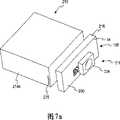
图7a为根据本发明的一个实施例的测试传感器盒和弹射机构的透视图,所述弹射机构可拆卸地连接于所述测试传感器盒上;Figure 7a is a perspective view of a test sensor cartridge and an ejection mechanism detachably attached to the test sensor cartridge according to one embodiment of the present invention;
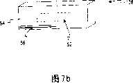
图7b为图7a中弹射机构外壳后部的透视图;Figure 7b is a perspective view of the rear of the ejection mechanism housing in Figure 7a;
图8为一个测量计的透视图,其中图5中的弹射机构被连接于本发明的一个实施例的内部;Figure 8 is a perspective view of a gauge with the ejection mechanism of Figure 5 attached to the interior of an embodiment of the present invention;
图9为连接于图8中的测量计外部的图6中的弹射机构的透视图。9 is a perspective view of the ejection mechanism of FIG. 6 attached to the outside of the gauge of FIG. 8 .
具体实施方式Detailed ways
本发明涉及一种用于分配测试传感器的可分配测试传感器盒和弹射机构。从所述盒内弹出的测试传感器(例如,生物传感器)可用于确定流体样品中的分析物浓度,例如血液或体液。可被收集和分析的这些类型的分析物的一些例子包括葡萄糖、酯类(lipid profiles)(例如,胆固醇,甘油三酯,LDL和HDL),微白蛋白、血红蛋白A1C、果糖、乳酸盐、或胆红素。体液中分析物的数量确定在某些生理异常的诊断和维持方面非常重要。特别是,确定体液中的葡萄糖对于必须经常测试体液中葡萄糖水平以便调节他们饮食中的葡萄糖吸收的糖尿病患者非常重要。每次测试需要使用新的测试传感器,因此,一天中可能使用很多测试条。包含很多测试传感器的盒用于允许使用者大致在单个目标内携带多个试验片。这些盒也可直接被并入一个仪器或相似的装置中。然后,用所述仪器或相似装置对血液或体液样品进行分析以便确定所检测的分析物的浓度。The present invention relates to a dispensable test sensor cartridge and ejection mechanism for dispensing test sensors. A test sensor (eg, a biosensor) ejected from the cartridge can be used to determine the analyte concentration in a fluid sample, such as blood or body fluid. Some examples of these types of analytes that can be collected and analyzed include glucose, lipid profiles (e.g., cholesterol, triglycerides, LDL and HDL), microalbumin, hemoglobin A1C, fructose, lactate, or bilirubin. Quantitative determination of analytes in body fluids is important in the diagnosis and maintenance of certain physiological abnormalities. In particular, determination of glucose in body fluids is important for diabetics who must frequently test glucose levels in body fluids in order to regulate glucose absorption in their diet. Each test requires the use of a new test sensor, so many test strips may be used in a day. Cartridges containing many test sensors are used to allow the user to carry multiple test strips generally within a single target. The cartridges can also be incorporated directly into an instrument or similar device. The blood or body fluid sample is then analyzed using the instrument or similar device to determine the concentration of the detected analyte.
现在转向附图并且从图1-2开始,说明了根据本发明第一个实施例的测试传感器盒10。所述测试传感器盒10包括基底12,顶盖13,和从基底12延伸并且支撑所述顶盖13的两个相对的侧壁14a,14b。所述盒还包括从基底12延伸并且支撑所述顶盖13的面16和后面18。所述盒10在内腔21内适于包含多个测试传感器20,所述内腔21由侧壁14a-b,面16和后面18形成并且位于基底12和顶盖13之间。Turning now to the drawings and beginning with FIGS. 1-2 , a
所述盒10还包括位于内腔21内的测试传感器保存机构22。所述测试传感器保存机构22包括保持板22a和多个弹簧22b,c。所述测试传感器20堆叠在盒10的面16和保持板22a之间。所述保存机构22用于确保所述测试传感器彼此保持接触并且与所述面16的内表面齐平。所述测试传感器保持机构22驱动所述测试传感器20朝向面16的内表面。所述弹簧22b,c位于保持板22a和后面18之间并且既连接于保持板22a上又连接于后面18上。例如,所述弹簧22b,c可通过将从后面18延伸的突起19和从保持板22a延伸的另一个突起插入弹簧22b,c的中心孔中进行连接。可以设想,所述弹簧22b,c可以通过其他方法进行连接。所述弹簧22b,c沿着面16的方向提供了一个作用于保持板22a上的力。尽管所述实施例说明了通常将力施加于保持板22a上的两个弹簧22b,c,但是应该注意到,可以使用不同数目的弹簧,例如一个弹簧。The
参考图3,盒10的面16形成了一个通常与基底12平行的狭槽24。所述狭槽24适于允许通过狭槽24插入弹射机构11(图5a)。开始时,所述狭槽被密封,例如,通过将金属薄片连接于盒10的面16上。密封狭槽能够保护堆叠的测试传感器不受潮。所述侧壁14a具有与所述基底12垂直的弹射狭缝25以便足以允许所述测试传感器一次一个地从所述盒10中弹出。Referring to FIG. 3 , face 16 of
图3也说明了一个位于盒10的狭槽24附近的可移动的齿条26。所述可移动的齿条26包括从那里延伸的脚部27。如图4中所示,所述脚部27设计用于在与面16的内表面平齐的测试传感器的端部后面通过狭槽24插入。所述脚部27设计用于仅与最接近测试传感器盒10的面16的一个测试传感器20接触。当所述脚部27通过狭槽24插入时,所述可移动的齿条26适于可拆卸地与所述盒10连接。所述脚部27可从待命位置到弹射位置往复移动。可以预计,在这里所描述的脚部27的位置,也可以采用其他类型的弹射方案和装置。FIG. 3 also illustrates a
图5a-b说明了具有连接于所述盒10的面16的固定齿条28的图1-2中的盒10。所述可移动齿条26已经借助于通过狭槽24将脚部27插入可拆卸地连接于所述盒10。所述固定齿条28固定于盒10的面16上,而可移动齿条26被定位于覆盖狭槽24的位置。齿轮30位于固定齿条28和可移动齿条26之间。齿轮30既与固定齿条28接触也与可移动齿条26接触。齿轮30、固定齿条28和可移动齿条26都包含齿。齿轮30的齿适于插入固定齿条28和可移动齿条26的齿之间。齿轮30具有穿过中心孔(未示出)的中间部分32和连接于中间部分32的滑动器34。当使用者移动滑动器34时,允许齿轮30在中间部分32上旋转。Figures 5a-b illustrate the
齿轮30和齿条26,28为双齿条和小齿轮构造。因此,当滑动器34从固定位置(图5a)到弹射位置(图5b)横向移动时-沿着箭头A的方向(图5a-b)-齿轮30也横向移动并且固定齿条28使齿轮30沿顺时针方向旋转。无论是齿轮30的横向移动还是齿轮30的旋转都能够使可移动齿条26沿着箭头A的方向横向移动。例如,当滑动器34横向移动距离X时,齿轮30同样横向移动一个X距离,这使得可移动齿条26移动一个横向距离X。另外,当齿轮30横向移动时,固定齿条26使齿轮30(即,所述小齿轮)顺时针旋转(在所述实施例中)。基于齿轮30的尺寸以及齿轮30和齿条26,28的齿的构造,这样的旋转使可移动齿条进一步移动一个距离Y。这样,滑动器34沿箭头A的方向横向移动一个距离X使得可移动齿条26沿箭头A的方向横向移动一个距离X+Y。The
如上所述,可移动齿条的脚部27位于离面16最近的测试传感器20的后部。因此,当所述滑动器34横向移动一个距离X时,所述测试传感器20沿着与滑动器34相同的方向横向移动一个X+Y的距离。当可移动齿条26沿着箭头A的方向横向移动时,最接近盒的面16的测试传感器20借助于脚部27通过弹射狭缝25部分弹出。当测试传感器20被取出时,所述测试传感器保持机构22朝着面16对保持堆叠的测试传感器20施加压力,直到下一个最接近的测试传感器20与面16平齐。As mentioned above, the
弹簧36靠近离弹射狭缝25最近的可移动齿条设置。当可移动齿条26朝着弹射狭缝25移动时,所述弹簧36受到压缩,因此,当滑动器34得到释放时,弹簧36的回程力使可移动齿条26返回到起始位置以便弹射其他的测试传感器20。A
如上所述,在一些实施例中,狭槽24可以用箔片密封,例如,通过Alusuisse Flexible Packaging公司经销的箔片AL-191-01密封。此外,弹射狭缝25也可以用箔片密封。在这些实施例中,当被连接到所述盒10上时,所述脚部27开始刺穿狭槽24的箔片密封。然后,当滑动器34沿着箭头A的方向横向移动时,所述脚部27切开密封狭槽24的箔片密封。当所述脚部27沿着箭头A的方向移动时,测试传感器20被从盒10中分配。被分配的测试传感器20首先切开密封弹射狭缝25的箔片。As noted above, in some embodiments,
现在转向图6,弹射机构111位于外壳38内并且连接于根据本发明另一个实施例的盒110上。所述弹射机构111包括固定齿条128,在一端具有脚部的可移动齿条126,弹簧136和齿轮130,所有的部件部分地被都封闭在外壳38内。所述外壳38包括底部40,顶部42,和前部50。所述外壳38还包括从底部40延伸到顶部42的两个侧边44a和44b。盒110的面116作为外壳38的后壁。面116包括如图1和3中的狭槽24的小尺寸狭槽,所述脚部通过该狭槽伸出。所述底部40提供了一个供可移动齿条126在其上滑动的路径。外壳38的底部40和前部50同样将可移动齿条126和弹簧136保持在适当位置,确保所述脚部保持被定位在狭槽内。所述前部50具有适于允许中心部分132延伸通过的孔52。所述滑动器134位于外壳38外部,这样使用者可以接近它。所述孔52适于允许使用者移动滑动器134以便测试传感器能够被弹射。Turning now to FIG. 6, an
现在转向图7a-b,说明了根据本发明另一个实施例的可移动外壳138。所述可移动外壳138可拆卸地连接于盒210。除了可移动外壳138具有固定在那里以充分地封闭弹射机构211的后部54外,可移动外壳138与图6中的外壳38相似。可移动外壳138包括与图6中的外壳38相同的内部特点。在图7a-b中说明的实施例中,狭槽56在可移动外壳138的后部54中形成。盒210在前面216上具有与在图1中盒上形成的狭槽24相同尺寸的狭槽。狭槽56具有与盒10中形成的狭槽24相同的尺寸并且适于允许可移动齿条226的脚部从那里延伸通过。当可移动外壳138可拆卸地连接于盒210时,所述狭槽56与盒210的前面216上的狭槽对齐以便可移动齿条226的脚部通过狭槽插入到盒210内。当所述脚部被这样插入时,所述弹射机构211可以从盒210中分配测试传感器。Turning now to Figures 7a-b, a
可移动外壳138的后部54适于可拆卸地连接于盒210的面216。可拆卸地连接可以通过不同的装置获得,包括但并不限于狭槽和沟槽连接、一个或多个闭锁机构、胶粘剂等。The
如图8所示,根据本发明的一些实施例,盒110或210以及外壳38或可移动外壳138适于插入到仪器100中。根据一个实施例,仪器100包括显示器62,读出头60,包括多个按钮64a-c的按钮组64。当按钮组64允许使用者使用仪器100时,所述读出头60适于从施加于测试传感器20的流体样品中获得一个读数。所述仪器100被调节以便盒的侧壁最接近仪器100的第一表面66和第二表面68。第一表面66包括与盒的弹射狭槽对齐的测试传感器弹出孔70,这样当测试传感器通过盒的弹射狭槽被弹射时,能够通过测试传感器弹射孔70弹射。邻近的第二表面68包括允许使用者接近和移动滑动器334的狭槽开口72。所述狭槽开口72适于允许弹射机构111,211的中心部分从固定位置到测试位置往复移动。在一个可替换的实施例中,图7a-b中的弹射机构211和外壳138最初被封闭在仪器100内,随后可将盒210插入仪器100内以便盒210的面216与外壳138的后面54平齐并且盒210的侧壁214a与仪器100的第一表面66平齐。当盒210被正确插入时,弹射狭槽225与仪器100上形成的测试传感器弹射孔70对齐。As shown in FIG. 8 ,
现在参考图9,根据本发明的一个实施例,图7a-b中的弹射机构111和211被连接于仪器200上。所述弹射机构111和211被连接于仪器200的外表面76上。外壳138的后部54(图7b)适于与盒的面216接触以便外壳138的狭槽56与盒210的面216上的狭槽对齐。在该实施例中,盒210在使用过程中保持在仪器200的外部。Referring now to FIG. 9,
可选择的实施例AAlternative Embodiment A
一种用于从测试传感器盒中弹射测试传感器的测试传感器弹射机构,所述弹射机构包括:A test sensor ejection mechanism for ejecting a test sensor from a test sensor cartridge, the ejection mechanism comprising:
固定于表面上的固定齿条;a fixed rack fixed to the surface;
通常与固定齿条平行设置的可移动齿条,所述可移动齿条适于与测试传感器接合;和a movable rack disposed generally parallel to the fixed rack, the movable rack being adapted to engage the test sensor; and
位于固定齿条和可移动齿条之间并且与它们接触的齿轮;a gear located between and in contact with the fixed and movable racks;
其中,所述齿轮沿着第一方向的横向移动通过齿轮产生了旋转运动,横向运动和旋转运动使可移动齿条沿着第一方向横向移动,可移动齿条沿着第一方向的横向移动将测试传感器从测试传感器盒中弹出。Wherein, the lateral movement of the gear along the first direction generates rotational motion through the gear, the lateral motion and the rotational motion cause the movable rack to move laterally along the first direction, and the movable rack moves laterally along the first direction Pop the test sensor out of the test sensor box.
可选择的实施例BAlternative embodiment B
实施例A中的测试传感器弹射机构,其中可移动齿条移动的横向距离为齿轮移动的距离的两倍。The test sensor ejection mechanism in Example A where the movable rack travels twice the lateral distance that the gear travels.
可选择的实施例CAlternative embodiment C
实施例A中的测试传感器弹射机构进一步包括机械地连接于齿轮上的滑动器,其中滑动器沿着第一方向的移动使齿轮沿着所述第一方向移动。The test sensor ejection mechanism of embodiment A further includes a slider mechanically coupled to the gear, wherein movement of the slider in a first direction moves the gear in the first direction.
可选择的实施例DAlternative embodiment D
实施例A中的测试传感器弹射机构,其中弹射机构至少部分地被外壳封闭。The test sensor ejection mechanism of Embodiment A, wherein the ejection mechanism is at least partially enclosed by the housing.
可选择的实施例EAlternative Embodiment E
实施例D中的测试传感器弹射机构,其中所述外壳适于可拆卸地连接于仪器上。The test sensor ejection mechanism of Embodiment D, wherein the housing is adapted to be detachably attached to the instrument.
可选择的实施例FAlternative embodiment F
实施例D中的测试传感器弹射机构,其中所述外壳适于可拆卸地连接于测试传感器盒上。The test sensor ejection mechanism of Embodiment D, wherein the housing is adapted to be detachably attached to the test sensor cartridge.
可选择的实施例GAlternative embodiment G
实施例A中的测试传感器弹射机构,其中测试传感器适于帮助确定流体样品中分析物的浓度。The test sensor ejection mechanism of Embodiment A, wherein the test sensor is adapted to assist in determining the concentration of the analyte in the fluid sample.
可旋转的实施例HRotatable Embodiment H
实施例G中的测试传感器弹射机构,其中所述分析物为葡萄糖并且流体样品为全血。The test sensor ejection mechanism of Embodiment G, wherein the analyte is glucose and the fluid sample is whole blood.
可选择的实施例IAlternative Embodiment I
一种测试传感器弹射机构,用于从测试传感器盒中弹射测试传感器,所述弹射机构包括:A test sensor ejection mechanism for ejecting a test sensor from a test sensor box, the ejection mechanism comprising:
固定于盒的面上的固定齿条;a fixed rack fixed on the face of the box;
与固定齿条平行设置的可移动齿条,所述可移动齿条具有从其上伸出的脚部;a movable rack disposed parallel to the fixed rack, the movable rack having feet extending therefrom;
在盒的面上形成的狭槽,所述狭槽适于允许所述脚部延伸通过其并且与测试传感器接触;a slot formed in a face of the case adapted to allow the foot to extend therethrough and contact the test sensor;
设置在固定齿条和可移动齿条之间并且与它们接触的齿轮,所述齿轮具有在其内形成的中心孔;a gear disposed between and in contact with the fixed rack and the movable rack, the gear having a central hole formed therein;
通过齿轮的中心孔的齿轮中心部分;和the center portion of the gear passing through the center hole of the gear; and
连接于齿轮中心部分上的滑动器,a slider attached to the center part of the gear,
其中,滑动器沿第一方向的横向移动使齿轮沿第一方向移动,这通过齿轮产生了旋转运动,横向运动和旋转运动驱动可移动齿条沿着第一方向运动,可移动齿条沿着第一方向的横向运动将测试传感器从测试传感器盒中弹出。Wherein, the lateral movement of the slider along the first direction causes the gear to move along the first direction, which generates rotational motion through the gear, the lateral motion and the rotational motion drive the movable rack to move along the first direction, and the movable rack moves along the Lateral movement in a first direction ejects the test sensor from the test sensor cartridge.
可选择的实施例JAlternative Embodiment J
实施例I中的测试传感器弹射机构,其中所述盒包括多个位于其内的测试传感器。The test sensor ejection mechanism of embodiment I, wherein the cartridge includes a plurality of test sensors located therein.
可选择的实施例KAlternative embodiment K
实施例J中的测试传感器弹射机构,其中所述盒包括用于将多个测试传感器中的一个与所述盒的面平齐的测试传感器保持机构。The test sensor ejection mechanism of Embodiment J, wherein the cartridge includes a test sensor retention mechanism for flushing one of the plurality of test sensors with a face of the cartridge.
可选择的实施例LAlternative embodiment L
实施例K中的测试传感器弹射机构,其中所述弹射机构和所述盒适于插入到仪器中。The test sensor ejection mechanism of Embodiment K, wherein said ejection mechanism and said cartridge are adapted to be inserted into an instrument.
可选择的实施例MAlternative embodiment M
实施例K中的测试传感器弹射机构,其中所述弹射机构和所述盒适于可拆卸地连接于仪器上。The test sensor ejection mechanism of embodiment K, wherein said ejection mechanism and said cartridge are adapted to be detachably attached to an instrument.
可选择的实施例NAlternative Embodiment N
一种测试传感器分配装置,包括:A test sensor dispensing device comprising:
形成中央室的测试传感器盒,包括:A test sensor box forming the central chamber, consisting of:
(i)从基底到顶盖延伸的面和端壁,(i) the faces and end walls extending from the base to the roof,
(ii)位于盒的中央室内的多个堆叠的测试传感器,(ii) a plurality of stacked test sensors located within the central chamber of the cassette,
(iii)位于盒中央室内的测试传感器保存机构,所述保存机构包括保持板和至少一个弹簧,所述至少一个弹簧在一端连接于保持板上,在另一端连接于盒的端壁上,和(iii) a test sensor retention mechanism located within the central compartment of the cassette, said retention mechanism comprising a retaining plate and at least one spring attached at one end to the retaining plate and at the other end to an end wall of the cassette, and
(iv)通常平行于盒的面的测试传感器弹射槽,所述弹射槽适于允许多个测试传感器中的一个被从盒中弹出;和(iv) a test sensor ejection slot generally parallel to a face of the cartridge adapted to allow one of the plurality of test sensors to be ejected from the cartridge; and
弹射机构,包括Ejection mechanism, including
(i)固定于测试传感器盒的面上的固定齿条,(i) a fixed rack fixed to the face of the test sensor box,
(ii)通常与固定齿条平行设置的可移动齿条,所述可移动齿条具有从其上延伸的脚部,(ii) a movable rack disposed generally parallel to the fixed rack, said movable rack having feet extending therefrom,
(iii)位于测试传感器盒的面上的狭槽开口,所述狭槽开口适于允许所述脚部延伸通过其并且与多个测试传感器中的一个接合,(iii) a slot opening on a face of the test sensor cartridge adapted to allow the foot to extend therethrough and engage one of the plurality of test sensors,
(iv)位于固定齿条和可移动齿条之间并且与它们接触的齿轮,所述齿轮具有在其内形成的中心孔,(iv) a gear located between and in contact with a fixed rack and a movable rack, said gear having a central hole formed therein,
(v)通过齿轮的中心孔的齿轮中心部分,所述齿轮中心部分允许齿轮在其上旋转,和(v) a gear center portion passing through the center hole of the gear, said gear center portion allowing the gear to rotate thereon, and
(vi)连接于齿轮中心部分上的滑动器,(vi) a slider attached to the center portion of the gear,
其中,滑动器沿着第一方向的横向运动使所述齿轮沿着第一方向运动,由此通过齿轮产生了旋转运动,横向运动和旋转运动使可移动齿条沿着第一方向横向运动,可移动齿条沿着第一方向的横向运动基底通过弹射狭槽将测试传感器从测试传感器盒弹出。wherein the lateral movement of the slider along the first direction causes the gear to move along the first direction, thereby generating a rotational movement through the gear, the transverse movement and the rotational movement cause the movable rack to move laterally along the first direction, Lateral movement of the movable rack along the first direction ejects the test sensor from the test sensor cartridge through the eject slot.
可选择的实施例OAlternative Embodiment O
实施例N中的测试传感器分配装置,其中测试传感器分配装置连接于仪器上。The test sensor dispensing device of Embodiment N, wherein the test sensor dispensing device is attached to the instrument.
可选择的实施例PAlternative embodiment P
实施例N中的测试传感器分配装置,其中弹射机构被封闭于外壳内,所述外壳包括开口,齿轮中心部分和滑动器通过该开口伸出。The test sensor dispensing device of Embodiment N, wherein the ejection mechanism is enclosed within a housing that includes an opening through which the gear hub and slider protrude.
可选择的实施例QAlternative embodiment Q
实施例P中的测试传感器分配装置,其中测试传感器盒的面作为所述外壳的后壁。The test sensor dispensing device of embodiment P, wherein the face of the test sensor cartridge serves as the rear wall of the housing.
可选择的实施例RAlternative embodiment R
实施例N中的测试传感器分配装置,其中狭槽开口开始用箔片密闭。The test sensor dispensing device in Example N, wherein the slot opening was initially sealed with a foil.
可选择的实施例SAlternative Embodiment S
实施例N中的测试传感器分配装置,其中弹射狭槽开始用箔片密闭。The test sensor dispensing device in Example N, where the ejection slot was initially sealed with a foil.
可选择的实施例TAlternative embodiment T
一种适于分配测试传感器的仪器,所述仪器包括:An apparatus suitable for dispensing test sensors, the apparatus comprising:
适于从被分配的测试传感器上的流体样品中确定分析物浓度的读出头;a read head adapted to determine the concentration of an analyte from the fluid sample on the dispensed test sensor;
为仪器的使用者显示信息的显示器;A display for displaying information for the user of the instrument;
允许使用者与仪器互动的按钮组;和a set of buttons that allow the user to interact with the instrument; and
弹射机构,包括Ejection mechanism, including
(i)固定于表面上的固定齿条,(i) a fixed rack fixed to a surface,
(ii)通常平行于固定齿条设置的可移动齿条,所述可移动齿条适于与测试传感器接合,和(ii) a movable rack disposed generally parallel to the fixed rack adapted to engage the test sensor, and
(iii)设置于固定齿条和运动齿条之间并且与它们接触的齿轮,(iii) a gear disposed between and in contact with a fixed rack and a moving rack,
其中,所述齿轮沿着第一方向的横向运动通过齿轮产生了旋转运动,横向运动和旋转运动使可移动齿条沿着第一方向横向运动,所述可移动齿条沿着第一方向的横向运动使测试传感器从测试传感器盒中弹出。Wherein, the lateral movement of the gear along the first direction generates a rotational movement through the gear, and the lateral movement and the rotational movement make the movable rack move laterally along the first direction, and the movable rack moves along the first direction. Lateral movement ejects the test sensor from the test sensor box.
可选择的实施例UAlternative embodiment U
实施例T中的仪器,其中所述分析物为葡萄糖并且流体样品为全血。The apparatus of Embodiment T, wherein the analyte is glucose and the fluid sample is whole blood.
可选择的实施例VAlternative Embodiment V
实施例T中的仪器,其中所述弹射机构连接于所述仪器的外表面上。The instrument of Embodiment T, wherein said ejection mechanism is attached to an outer surface of said instrument.
可选择的实施例WAlternative embodiment W
实施例T中的仪器,所述仪器进一步包括适于允许测试传感器盒插入仪器中的内腔,所述弹射机构连接于所述内腔上以便允许齿轮从仪器外部沿着第一方向横向地运动。The instrument of embodiment T further comprising a lumen adapted to allow a test sensor cartridge to be inserted into the instrument, the ejection mechanism being coupled to the lumen to allow the gear to move laterally in a first direction from outside the instrument .
尽管可对本发明进行各种修改和选择其他可替换的形式,但是借助于附图中的例子说明的是特定的实施例并在这里进行了详细描述。然而,应该理解,本发明并没有意图限定于这里描述的特定方式。相反,本发明涵盖了所有落入本发明精神和范围内的修改、等同和替代方式,本发明的精神和范围由所附权利要求限定。While the invention is susceptible to various modifications and alternative forms, specific embodiments are illustrated by way of example in the drawings and described herein in detail. It should be understood, however, that the invention is not intended to be limited to the particular forms described. On the contrary, the invention covers all modifications, equivalents and alternatives falling within the spirit and scope of the invention as defined by the appended claims.
Claims (23)
Applications Claiming Priority (2)
| Application Number | Priority Date | Filing Date | Title |
|---|---|---|---|
| US63718404P | 2004-12-17 | 2004-12-17 | |
| US60/637,184 | 2004-12-17 |
Publications (1)
| Publication Number | Publication Date |
|---|---|
| CN101080633Atrue CN101080633A (en) | 2007-11-28 |
Family
ID=36035665
Family Applications (1)
| Application Number | Title | Priority Date | Filing Date |
|---|---|---|---|
| CNA2005800432235APendingCN101080633A (en) | 2004-12-17 | 2005-12-16 | Disposable test sensor cartridge |
Country Status (11)
| Country | Link |
|---|---|
| US (1) | US8097210B2 (en) |
| EP (1) | EP1875231B8 (en) |
| JP (1) | JP2008524599A (en) |
| CN (1) | CN101080633A (en) |
| BR (1) | BRPI0518557A2 (en) |
| CA (1) | CA2592339C (en) |
| MX (1) | MX2007006886A (en) |
| NO (1) | NO20073660L (en) |
| RU (1) | RU2007127255A (en) |
| TW (1) | TW200632316A (en) |
| WO (1) | WO2006066123A1 (en) |
Cited By (1)
| Publication number | Priority date | Publication date | Assignee | Title |
|---|---|---|---|---|
| CN109881589A (en)* | 2019-04-12 | 2019-06-14 | 郑州市交通规划勘察设计研究院 | A kind of bridge construction component and the construction method using the construction component |
Families Citing this family (18)
| Publication number | Priority date | Publication date | Assignee | Title |
|---|---|---|---|---|
| CN101080633A (en)* | 2004-12-17 | 2007-11-28 | 拜尔保健有限公司 | Disposable test sensor cartridge |
| EP2426493B1 (en) | 2005-01-14 | 2018-10-03 | Ascensia Diabetes Care Holdings AG | Test sensor cartridges and sensor-dispensing instruments |
| DE602006014717D1 (en)* | 2005-03-22 | 2010-07-15 | Bayer Healthcare Llc | CARTRIDGE WITH WHEEL FOR OPENING CLOSURE |
| CN101166972A (en)* | 2005-04-25 | 2008-04-23 | 拜尔保健有限公司 | Sensor release mechanism for test meter |
| US8574510B2 (en)* | 2009-09-30 | 2013-11-05 | Bayer Healthcare Llc | Stackable electrochemical analyte sensors, systems and methods including same |
| CN103907024B (en) | 2011-10-20 | 2016-06-08 | 捷普电路股份有限公司 | For box and the measuring apparatus of fluid test bar |
| WO2013096268A1 (en)* | 2011-12-20 | 2013-06-27 | Bayer Heal Thcare Llc | Linear, cartridge-based glucose measurement system |
| US9097700B2 (en) | 2011-12-29 | 2015-08-04 | Bayer Healthcare Llc | Glucose measurement system with high-capacity cartridge and capability of more frequent replenishment |
| US9383333B2 (en) | 2012-05-31 | 2016-07-05 | Ascensia Diabetes Care Holdings Ag | Replaceable multistrip cartridge and biosensor meter |
| WO2013180755A1 (en) | 2012-05-31 | 2013-12-05 | Bayer Healthcare Llc | Multistrip cartridge |
| US9039876B2 (en) | 2012-06-29 | 2015-05-26 | Roche Diagnostics Operations, Inc. | Test strip ejector for medical device |
| US8715571B2 (en) | 2012-06-29 | 2014-05-06 | Roche Diagnostics Operations, Inc. | Test strip ejector for medical device |
| WO2014072370A1 (en)* | 2012-11-09 | 2014-05-15 | Roche Diagnostics Gmbh | Test strip ejector for medical device |
| JP6563892B2 (en) | 2013-03-11 | 2019-08-21 | アセンシア・ディアベティス・ケア・ホールディングス・アーゲー | Strip grabber |
| CA2904689A1 (en) | 2013-03-12 | 2014-10-09 | Bayer Healthcare Llc | Test strip meter with a mechanism for pushing the test strip against an optical reader |
| US9376708B2 (en) | 2013-03-13 | 2016-06-28 | Ascensia Diabetes Care Holdings Ag | Bottled glucose sensor with no handling |
| WO2015195487A1 (en) | 2014-06-19 | 2015-12-23 | Bayer Healthcare Llc | Sensor clip for stacked sensor dispensing system, and system using the same |
| US10945568B1 (en)* | 2019-09-17 | 2021-03-16 | Lianne Chase | Rubbing alcohol dispenser apparatus |
Family Cites Families (15)
| Publication number | Priority date | Publication date | Assignee | Title |
|---|---|---|---|---|
| US5510266A (en) | 1995-05-05 | 1996-04-23 | Bayer Corporation | Method and apparatus of handling multiple sensors in a glucose monitoring instrument system |
| DE19715031A1 (en) | 1997-04-11 | 1998-10-15 | Boehringer Mannheim Gmbh | Magazine for storing test elements |
| US6036924A (en) | 1997-12-04 | 2000-03-14 | Hewlett-Packard Company | Cassette of lancet cartridges for sampling blood |
| EP1296691B1 (en)* | 2000-06-30 | 2005-11-02 | Polydex Pharmaceuticals Limited | Use of cellulose sulfate and other sulfated polysaccharides to prevent and treat papilloma virus infections |
| GB0017737D0 (en)* | 2000-07-20 | 2000-09-06 | Hypoguard Limited | Test device |
| US7138089B2 (en) | 2000-07-20 | 2006-11-21 | Hypoguard Limited | Test device for analyzing blood glucose or other analytes in bodily fluids |
| US6827899B2 (en) | 2000-08-30 | 2004-12-07 | Hypoguard Limited | Test device |
| EP1328192B1 (en) | 2001-03-29 | 2011-01-05 | Lifescan Scotland Ltd | Integrated sample testing meter |
| US6988996B2 (en)* | 2001-06-08 | 2006-01-24 | Roche Diagnostics Operatons, Inc. | Test media cassette for bodily fluid testing device |
| US6997343B2 (en)* | 2001-11-14 | 2006-02-14 | Hypoguard Limited | Sensor dispensing device |
| US6908008B2 (en)* | 2001-12-21 | 2005-06-21 | Lifescan, Inc. | Test device with means for storing and dispensing diagnostic strips |
| JP3954393B2 (en)* | 2002-01-18 | 2007-08-08 | 松下電器産業株式会社 | Biosensor cartridge and biosensor dispensing apparatus with the same attached |
| US20030223906A1 (en) | 2002-06-03 | 2003-12-04 | Mcallister Devin | Test strip container system |
| CN101080633A (en)* | 2004-12-17 | 2007-11-28 | 拜尔保健有限公司 | Disposable test sensor cartridge |
| DE602006014717D1 (en)* | 2005-03-22 | 2010-07-15 | Bayer Healthcare Llc | CARTRIDGE WITH WHEEL FOR OPENING CLOSURE |
- 2005
- 2005-12-16CNCNA2005800432235Apatent/CN101080633A/enactivePending
- 2005-12-16TWTW094144916Apatent/TW200632316A/enunknown
- 2005-12-16JPJP2007546965Apatent/JP2008524599A/enactivePending
- 2005-12-16RURU2007127255/28Apatent/RU2007127255A/ennot_activeApplication Discontinuation
- 2005-12-16MXMX2007006886Apatent/MX2007006886A/enactiveIP Right Grant
- 2005-12-16BRBRPI0518557-2Apatent/BRPI0518557A2/ennot_activeIP Right Cessation
- 2005-12-16USUS11/792,602patent/US8097210B2/enactiveActive
- 2005-12-16EPEP05854466.9Apatent/EP1875231B8/ennot_activeNot-in-force
- 2005-12-16WOPCT/US2005/045760patent/WO2006066123A1/enactiveApplication Filing
- 2005-12-16CACA2592339Apatent/CA2592339C/ennot_activeExpired - Fee Related
- 2007
- 2007-07-17NONO20073660Apatent/NO20073660L/ennot_activeApplication Discontinuation
Cited By (2)
| Publication number | Priority date | Publication date | Assignee | Title |
|---|---|---|---|---|
| CN109881589A (en)* | 2019-04-12 | 2019-06-14 | 郑州市交通规划勘察设计研究院 | A kind of bridge construction component and the construction method using the construction component |
| CN109881589B (en)* | 2019-04-12 | 2021-04-27 | 郑州市交通规划勘察设计研究院 | Bridge construction assembly and construction method applying same |
Also Published As
| Publication number | Publication date |
|---|---|
| NO20073660L (en) | 2007-07-17 |
| US8097210B2 (en) | 2012-01-17 |
| BRPI0518557A2 (en) | 2008-11-25 |
| EP1875231A1 (en) | 2008-01-09 |
| WO2006066123A1 (en) | 2006-06-22 |
| MX2007006886A (en) | 2007-08-06 |
| RU2007127255A (en) | 2009-01-27 |
| EP1875231B8 (en) | 2016-06-01 |
| US20080181818A1 (en) | 2008-07-31 |
| CA2592339C (en) | 2013-04-02 |
| EP1875231B1 (en) | 2016-03-23 |
| JP2008524599A (en) | 2008-07-10 |
| CA2592339A1 (en) | 2006-06-22 |
| TW200632316A (en) | 2006-09-16 |
Similar Documents
| Publication | Publication Date | Title |
|---|---|---|
| CN101080633A (en) | Disposable test sensor cartridge | |
| EP1949099B1 (en) | Cartridge with a wheel for sealing the opening | |
| EP1321769B1 (en) | Test device with means for storing and dispensing diagnostic strips | |
| CN101061384A (en) | Sensor dispensing device and mechanism for extracting the sensor | |
| CN1432813A (en) | Test chip and strip distributor | |
| JP5126994B2 (en) | Integrated sensor for analyzing biological samples | |
| US8435447B2 (en) | Integrated meter for analyzing biological samples | |
| US7575457B2 (en) | Contact connector assembly for a sensor-dispensing instrument | |
| CN1407871A (en) | Body fluid measuring apparatus with lancet and lancet holder used for the measuring apparatus | |
| CN1728967A (en) | Body Fluid Testing Equipment | |
| CN1665447A (en) | Unit for piercing, and piercing device | |
| CN1404576A (en) | Sensor cartridge, sensor supply device, and measurement device | |
| CN101666809A (en) | analyzer | |
| CN1250331C (en) | Centrifugal separation device and analysis device having same | |
| JP4522014B2 (en) | Biosensor sheet, biosensor cartridge, and biosensor dispensing device | |
| JP2005207833A (en) | Optical device for turbidity detection, and turbidity detection device using it | |
| JP2010521666A (en) | Single sensor meter system that does not require sensor operation and method using the same | |
| EP1808232A1 (en) | Centrifugal separator and analyzer with the same | |
| JP4213014B2 (en) | Dispensing device | |
| CN101048232A (en) | Centrifugal separation device and analysis device equipped with the device | |
| WO2006059241A2 (en) | Analyte sensing device mounted on a flexible substrate | |
| HK1114902A (en) | Diagnostic system for determining substance concentrations in liquid samples | |
| HK1053701B (en) | Test device with means for storing and dispensing diagnostic strips | |
| BRPI0611080A2 (en) | multi-contact sensor connector with release mechanism |
Legal Events
| Date | Code | Title | Description |
|---|---|---|---|
| C06 | Publication | ||
| PB01 | Publication | ||
| C10 | Entry into substantive examination | ||
| SE01 | Entry into force of request for substantive examination | ||
| C02 | Deemed withdrawal of patent application after publication (patent law 2001) | ||
| WD01 | Invention patent application deemed withdrawn after publication | Open date:20071128 |