CN101067972A - Memory error-detecting and error-correcting coding circuit and method for reading and writing data utilizing the same - Google Patents
Memory error-detecting and error-correcting coding circuit and method for reading and writing data utilizing the sameDownload PDFInfo
- Publication number
- CN101067972A CN101067972ACN200710098602.5ACN200710098602ACN101067972ACN 101067972 ACN101067972 ACN 101067972ACN 200710098602 ACN200710098602 ACN 200710098602ACN 101067972 ACN101067972 ACN 101067972A
- Authority
- CN
- China
- Prior art keywords
- data
- bit
- circuit
- error
- xor
- Prior art date
- Legal status (The legal status is an assumption and is not a legal conclusion. Google has not performed a legal analysis and makes no representation as to the accuracy of the status listed.)
- Granted
Links
- 238000000034methodMethods0.000titleclaimsabstractdescription67
- 238000012937correctionMethods0.000claimsabstractdescription80
- 239000011159matrix materialSubstances0.000claimsabstractdescription71
- 238000003860storageMethods0.000claimsabstractdescription14
- 230000005540biological transmissionEffects0.000claimsabstractdescription11
- 208000011580syndromic diseaseDiseases0.000claimsdescription31
- 239000000284extractSubstances0.000claimsdescription11
- 238000007689inspectionMethods0.000claimsdescription10
- 238000000605extractionMethods0.000claimsdescription8
- 230000014759maintenance of locationEffects0.000abstract1
- 238000013461designMethods0.000description6
- 238000005516engineering processMethods0.000description4
- 241001269238DataSpecies0.000description3
- 230000002950deficientEffects0.000description2
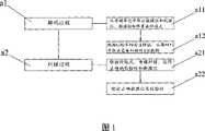
- 238000010586diagramMethods0.000description2
- 238000003780insertionMethods0.000description2
- 230000037431insertionEffects0.000description2
- 230000005039memory spanEffects0.000description2
- 238000005457optimizationMethods0.000description2
- JJWKPURADFRFRB-UHFFFAOYSA-Ncarbonyl sulfideChemical compoundO=C=SJJWKPURADFRFRB-UHFFFAOYSA-N0.000description1
- 238000001514detection methodMethods0.000description1
- 230000006866deteriorationEffects0.000description1
- 238000011161developmentMethods0.000description1
- 239000012467final productSubstances0.000description1
- 230000010354integrationEffects0.000description1
- 230000007774longtermEffects0.000description1
- 238000004519manufacturing processMethods0.000description1
- 239000000463materialSubstances0.000description1
- 230000002093peripheral effectEffects0.000description1
- 238000012360testing methodMethods0.000description1
- 238000012795verificationMethods0.000description1
Images


Landscapes
- Error Detection And Correction (AREA)
- Techniques For Improving Reliability Of Storages (AREA)
- Detection And Correction Of Errors (AREA)
Abstract
Description
Claims (9)
Priority Applications (1)
| Application Number | Priority Date | Filing Date | Title |
|---|---|---|---|
| CN2007100986025ACN101067972B (en) | 2007-04-23 | 2007-04-23 | Memory error-detecting and error-correcting coding circuit and method for reading and writing data utilizing the same |
Applications Claiming Priority (1)
| Application Number | Priority Date | Filing Date | Title |
|---|---|---|---|
| CN2007100986025ACN101067972B (en) | 2007-04-23 | 2007-04-23 | Memory error-detecting and error-correcting coding circuit and method for reading and writing data utilizing the same |
Publications (2)
| Publication Number | Publication Date |
|---|---|
| CN101067972Atrue CN101067972A (en) | 2007-11-07 |
| CN101067972B CN101067972B (en) | 2012-04-25 |
Family
ID=38880485
Family Applications (1)
| Application Number | Title | Priority Date | Filing Date |
|---|---|---|---|
| CN2007100986025AActiveCN101067972B (en) | 2007-04-23 | 2007-04-23 | Memory error-detecting and error-correcting coding circuit and method for reading and writing data utilizing the same |
Country Status (1)
| Country | Link |
|---|---|
| CN (1) | CN101067972B (en) |
Cited By (60)
| Publication number | Priority date | Publication date | Assignee | Title |
|---|---|---|---|---|
| CN101950586A (en)* | 2009-03-27 | 2011-01-19 | 联发科技股份有限公司 | Storage controller and method for controlling data reading |
| CN101533671B (en)* | 2008-03-10 | 2013-03-13 | 海力士半导体有限公司 | Non-volatile memory device and method of operating the same |
| CN101930799B (en)* | 2009-06-23 | 2013-05-29 | 北京兆易创新科技股份有限公司 | Non-volatile memory with error checking/correcting circuit and methods thereof for reading and writing data |
| CN101794623B (en)* | 2009-06-01 | 2013-11-06 | 深圳市朗科科技股份有限公司 | Error correction device of storage device and method thereof |
| CN103456355A (en)* | 2012-05-31 | 2013-12-18 | 上海华虹集成电路有限责任公司 | EEPROM interface circuit |
| CN104981874A (en)* | 2013-02-04 | 2015-10-14 | 美光科技公司 | Apparatus and method for target refresh of memory |
| CN106328209A (en)* | 2015-06-30 | 2017-01-11 | 中国科学院电子学研究所 | Storage single event multiple bit upset fault-tolerance method and circuit |
| CN106407037A (en)* | 2015-07-27 | 2017-02-15 | 中国科学院电子学研究所 | Dual-port memory word line control circuit |
| CN107192929A (en)* | 2017-06-21 | 2017-09-22 | 贵州电网有限责任公司电力科学研究院 | The GIS Partial discharge signals source system and application method verified for superfrequency monitoring system |
| CN107301881A (en)* | 2017-06-30 | 2017-10-27 | 哈尔滨工业大学 | It is a kind of based on 4 adjacent and 3 burst error correction codes SRAM memory radiation hardening methods and accumulator system |
| CN107454072A (en)* | 2017-07-28 | 2017-12-08 | 中国人民解放军信息工程大学 | A kind of control methods of multichannel data content and device |
| US9922694B2 (en) | 2014-05-21 | 2018-03-20 | Micron Technology, Inc. | Apparatuses and methods for controlling refresh operations |
| CN107993687A (en)* | 2018-01-12 | 2018-05-04 | 成都信息工程大学 | A kind of memory circuitry |
| CN108242973A (en)* | 2016-12-26 | 2018-07-03 | 北京邮电大学 | A data error correction method and device |
| CN108540138A (en)* | 2018-04-16 | 2018-09-14 | 中国科学院微电子研究所 | CSRAA coding circuit and encoder |
| US10134461B2 (en) | 2013-08-26 | 2018-11-20 | Micron Technology, Inc. | Apparatuses and methods for selective row refreshes |
| US20190267077A1 (en) | 2016-03-31 | 2019-08-29 | Micron Technology, Inc. | Semiconductor device |
| US10580475B2 (en) | 2018-01-22 | 2020-03-03 | Micron Technology, Inc. | Apparatuses and methods for calculating row hammer refresh addresses in a semiconductor device |
| CN111124741A (en)* | 2019-12-12 | 2020-05-08 | 上海高性能集成电路设计中心 | Enhanced type checking and error correcting device facing memory characteristics |
| CN111294059A (en)* | 2019-12-26 | 2020-06-16 | 成都海光集成电路设计有限公司 | Encoding method, decoding method, error correction method and related device |
| US10770127B2 (en) | 2019-02-06 | 2020-09-08 | Micron Technology, Inc. | Apparatuses and methods for managing row access counts |
| US10943636B1 (en) | 2019-08-20 | 2021-03-09 | Micron Technology, Inc. | Apparatuses and methods for analog row access tracking |
| US10964378B2 (en) | 2019-08-22 | 2021-03-30 | Micron Technology, Inc. | Apparatus and method including analog accumulator for determining row access rate and target row address used for refresh operation |
| US11043254B2 (en) | 2019-03-19 | 2021-06-22 | Micron Technology, Inc. | Semiconductor device having cam that stores address signals |
| CN113140252A (en)* | 2020-01-16 | 2021-07-20 | 三星电子株式会社 | Error correction circuit of semiconductor memory device and semiconductor memory device |
| US11069393B2 (en) | 2019-06-04 | 2021-07-20 | Micron Technology, Inc. | Apparatuses and methods for controlling steal rates |
| US11139015B2 (en) | 2019-07-01 | 2021-10-05 | Micron Technology, Inc. | Apparatuses and methods for monitoring word line accesses |
| US11152050B2 (en) | 2018-06-19 | 2021-10-19 | Micron Technology, Inc. | Apparatuses and methods for multiple row hammer refresh address sequences |
| US11158373B2 (en) | 2019-06-11 | 2021-10-26 | Micron Technology, Inc. | Apparatuses, systems, and methods for determining extremum numerical values |
| US11158364B2 (en) | 2019-05-31 | 2021-10-26 | Micron Technology, Inc. | Apparatuses and methods for tracking victim rows |
| US11200942B2 (en) | 2019-08-23 | 2021-12-14 | Micron Technology, Inc. | Apparatuses and methods for lossy row access counting |
| US11222683B2 (en) | 2018-12-21 | 2022-01-11 | Micron Technology, Inc. | Apparatuses and methods for staggered timing of targeted refresh operations |
| US11222686B1 (en) | 2020-11-12 | 2022-01-11 | Micron Technology, Inc. | Apparatuses and methods for controlling refresh timing |
| US11222682B1 (en) | 2020-08-31 | 2022-01-11 | Micron Technology, Inc. | Apparatuses and methods for providing refresh addresses |
| US11227649B2 (en) | 2019-04-04 | 2022-01-18 | Micron Technology, Inc. | Apparatuses and methods for staggered timing of targeted refresh operations |
| US11264079B1 (en) | 2020-12-18 | 2022-03-01 | Micron Technology, Inc. | Apparatuses and methods for row hammer based cache lockdown |
| US11264096B2 (en) | 2019-05-14 | 2022-03-01 | Micron Technology, Inc. | Apparatuses, systems, and methods for a content addressable memory cell with latch and comparator circuits |
| US11270750B2 (en) | 2018-12-03 | 2022-03-08 | Micron Technology, Inc. | Semiconductor device performing row hammer refresh operation |
| US11302377B2 (en) | 2019-10-16 | 2022-04-12 | Micron Technology, Inc. | Apparatuses and methods for dynamic targeted refresh steals |
| US11302374B2 (en) | 2019-08-23 | 2022-04-12 | Micron Technology, Inc. | Apparatuses and methods for dynamic refresh allocation |
| US11309010B2 (en) | 2020-08-14 | 2022-04-19 | Micron Technology, Inc. | Apparatuses, systems, and methods for memory directed access pause |
| US11315619B2 (en) | 2017-01-30 | 2022-04-26 | Micron Technology, Inc. | Apparatuses and methods for distributing row hammer refresh events across a memory device |
| US11348631B2 (en) | 2020-08-19 | 2022-05-31 | Micron Technology, Inc. | Apparatuses, systems, and methods for identifying victim rows in a memory device which cannot be simultaneously refreshed |
| US11380382B2 (en) | 2020-08-19 | 2022-07-05 | Micron Technology, Inc. | Refresh logic circuit layout having aggressor detector circuit sampling circuit and row hammer refresh control circuit |
| US11386946B2 (en) | 2019-07-16 | 2022-07-12 | Micron Technology, Inc. | Apparatuses and methods for tracking row accesses |
| US11424005B2 (en) | 2019-07-01 | 2022-08-23 | Micron Technology, Inc. | Apparatuses and methods for adjusting victim data |
| US11462291B2 (en) | 2020-11-23 | 2022-10-04 | Micron Technology, Inc. | Apparatuses and methods for tracking word line accesses |
| US11482275B2 (en) | 2021-01-20 | 2022-10-25 | Micron Technology, Inc. | Apparatuses and methods for dynamically allocated aggressor detection |
| US11532346B2 (en) | 2018-10-31 | 2022-12-20 | Micron Technology, Inc. | Apparatuses and methods for access based refresh timing |
| US11557331B2 (en) | 2020-09-23 | 2023-01-17 | Micron Technology, Inc. | Apparatuses and methods for controlling refresh operations |
| US11600314B2 (en) | 2021-03-15 | 2023-03-07 | Micron Technology, Inc. | Apparatuses and methods for sketch circuits for refresh binning |
| US11626152B2 (en) | 2018-05-24 | 2023-04-11 | Micron Technology, Inc. | Apparatuses and methods for pure-time, self adopt sampling for row hammer refresh sampling |
| CN115987304A (en)* | 2023-01-31 | 2023-04-18 | 浙江力积存储科技有限公司 | Error correction method, device and storage medium for data shielding |
| US11664063B2 (en) | 2021-08-12 | 2023-05-30 | Micron Technology, Inc. | Apparatuses and methods for countering memory attacks |
| US11688451B2 (en) | 2021-11-29 | 2023-06-27 | Micron Technology, Inc. | Apparatuses, systems, and methods for main sketch and slim sketch circuit for row address tracking |
| WO2024065794A1 (en)* | 2022-09-30 | 2024-04-04 | Intel Corporation | Evaluation and mitigation of soft-errors in parallel and distributed training and inference of transformers |
| US12002501B2 (en) | 2018-12-26 | 2024-06-04 | Micron Technology, Inc. | Apparatuses and methods for distributed targeted refresh operations |
| US12112787B2 (en) | 2022-04-28 | 2024-10-08 | Micron Technology, Inc. | Apparatuses and methods for access based targeted refresh operations |
| US12125514B2 (en) | 2022-04-28 | 2024-10-22 | Micron Technology, Inc. | Apparatuses and methods for access based refresh operations |
| US12165687B2 (en) | 2021-12-29 | 2024-12-10 | Micron Technology, Inc. | Apparatuses and methods for row hammer counter mat |
Family Cites Families (3)
| Publication number | Priority date | Publication date | Assignee | Title |
|---|---|---|---|---|
| IT1274925B (en)* | 1994-09-21 | 1997-07-29 | Texas Instruments Italia Spa | MEMORY ARCHITECTURE FOR SOLID STATE DISCS |
| CN1256005A (en)* | 1998-01-21 | 2000-06-07 | 索尼株式会社 | Encoding method and memory device |
| EP1657723B1 (en)* | 2003-08-18 | 2013-03-06 | Fujitsu Semiconductor Limited | Semiconductor memory and operation method of semiconductor memory |
- 2007
- 2007-04-23CNCN2007100986025Apatent/CN101067972B/enactiveActive
Cited By (98)
| Publication number | Priority date | Publication date | Assignee | Title |
|---|---|---|---|---|
| CN101533671B (en)* | 2008-03-10 | 2013-03-13 | 海力士半导体有限公司 | Non-volatile memory device and method of operating the same |
| CN101950586A (en)* | 2009-03-27 | 2011-01-19 | 联发科技股份有限公司 | Storage controller and method for controlling data reading |
| CN101950586B (en)* | 2009-03-27 | 2014-04-09 | 联发科技股份有限公司 | Storage controller and method for controlling data reading |
| CN101794623B (en)* | 2009-06-01 | 2013-11-06 | 深圳市朗科科技股份有限公司 | Error correction device of storage device and method thereof |
| CN101930799B (en)* | 2009-06-23 | 2013-05-29 | 北京兆易创新科技股份有限公司 | Non-volatile memory with error checking/correcting circuit and methods thereof for reading and writing data |
| CN103456355A (en)* | 2012-05-31 | 2013-12-18 | 上海华虹集成电路有限责任公司 | EEPROM interface circuit |
| US10861519B2 (en) | 2013-02-04 | 2020-12-08 | Micron Technology, Inc. | Apparatuses and methods for targeted refreshing of memory |
| CN104981874A (en)* | 2013-02-04 | 2015-10-14 | 美光科技公司 | Apparatus and method for target refresh of memory |
| US10147472B2 (en) | 2013-02-04 | 2018-12-04 | Micron Technology, Inc. | Apparatuses and methods for targeted refreshing of memory |
| US9741409B2 (en) | 2013-02-04 | 2017-08-22 | Micron Technology, Inc. | Apparatuses and methods for targeted refreshing of memory |
| US10811066B2 (en) | 2013-02-04 | 2020-10-20 | Micron Technology, Inc. | Apparatuses and methods for targeted refreshing of memory |
| US10134461B2 (en) | 2013-08-26 | 2018-11-20 | Micron Technology, Inc. | Apparatuses and methods for selective row refreshes |
| US10930335B2 (en) | 2013-08-26 | 2021-02-23 | Micron Technology, Inc. | Apparatuses and methods for selective row refreshes |
| US11361808B2 (en) | 2013-08-26 | 2022-06-14 | Micron Technology, Inc. | Apparatuses and methods for selective row refreshes |
| US9922694B2 (en) | 2014-05-21 | 2018-03-20 | Micron Technology, Inc. | Apparatuses and methods for controlling refresh operations |
| US10607686B2 (en) | 2014-05-21 | 2020-03-31 | Micron Technology, Inc. | Apparatuses and methods for controlling refresh operations |
| US10867660B2 (en) | 2014-05-21 | 2020-12-15 | Micron Technology, Inc. | Apparatus and methods for controlling refresh operations |
| US10153031B2 (en) | 2014-05-21 | 2018-12-11 | Micron Technology, Inc. | Apparatuses and methods for controlling refresh operations |
| CN106328209A (en)* | 2015-06-30 | 2017-01-11 | 中国科学院电子学研究所 | Storage single event multiple bit upset fault-tolerance method and circuit |
| CN106328209B (en)* | 2015-06-30 | 2020-01-21 | 中国科学院电子学研究所 | Memory single-particle multi-bit upset fault-tolerant method and circuit |
| CN106407037A (en)* | 2015-07-27 | 2017-02-15 | 中国科学院电子学研究所 | Dual-port memory word line control circuit |
| CN106407037B (en)* | 2015-07-27 | 2019-04-02 | 中国科学院电子学研究所 | A kind of dual-ported memory Word line control circuit |
| US20190267077A1 (en) | 2016-03-31 | 2019-08-29 | Micron Technology, Inc. | Semiconductor device |
| US10950289B2 (en) | 2016-03-31 | 2021-03-16 | Micron Technology, Inc. | Semiconductor device |
| CN108242973A (en)* | 2016-12-26 | 2018-07-03 | 北京邮电大学 | A data error correction method and device |
| CN108242973B (en)* | 2016-12-26 | 2020-10-27 | 北京邮电大学 | Data error correction method and device |
| US11315619B2 (en) | 2017-01-30 | 2022-04-26 | Micron Technology, Inc. | Apparatuses and methods for distributing row hammer refresh events across a memory device |
| CN107192929B (en)* | 2017-06-21 | 2023-11-03 | 贵州电网有限责任公司电力科学研究院 | GIS partial discharge signal source system for checking ultrahigh frequency monitoring system and use method |
| CN107192929A (en)* | 2017-06-21 | 2017-09-22 | 贵州电网有限责任公司电力科学研究院 | The GIS Partial discharge signals source system and application method verified for superfrequency monitoring system |
| CN107301881B (en)* | 2017-06-30 | 2020-06-09 | 哈尔滨工业大学 | A radiation hardening method and memory system for SRAM memory based on 4-bit adjacent and 3-bit burst error correction codes |
| CN107301881A (en)* | 2017-06-30 | 2017-10-27 | 哈尔滨工业大学 | It is a kind of based on 4 adjacent and 3 burst error correction codes SRAM memory radiation hardening methods and accumulator system |
| CN107454072A (en)* | 2017-07-28 | 2017-12-08 | 中国人民解放军信息工程大学 | A kind of control methods of multichannel data content and device |
| CN107993687B (en)* | 2018-01-12 | 2023-08-11 | 成都信息工程大学 | a memory circuit |
| CN107993687A (en)* | 2018-01-12 | 2018-05-04 | 成都信息工程大学 | A kind of memory circuitry |
| US11322192B2 (en) | 2018-01-22 | 2022-05-03 | Micron Technology, Inc. | Apparatuses and methods for calculating row hammer refresh addresses in a semiconductor device |
| US10580475B2 (en) | 2018-01-22 | 2020-03-03 | Micron Technology, Inc. | Apparatuses and methods for calculating row hammer refresh addresses in a semiconductor device |
| CN108540138A (en)* | 2018-04-16 | 2018-09-14 | 中国科学院微电子研究所 | CSRAA coding circuit and encoder |
| CN108540138B (en)* | 2018-04-16 | 2022-05-17 | 中国科学院微电子研究所 | CSRAA coding circuit and encoder |
| US11626152B2 (en) | 2018-05-24 | 2023-04-11 | Micron Technology, Inc. | Apparatuses and methods for pure-time, self adopt sampling for row hammer refresh sampling |
| US11694738B2 (en) | 2018-06-19 | 2023-07-04 | Micron Technology, Inc. | Apparatuses and methods for multiple row hammer refresh address sequences |
| US11152050B2 (en) | 2018-06-19 | 2021-10-19 | Micron Technology, Inc. | Apparatuses and methods for multiple row hammer refresh address sequences |
| US11532346B2 (en) | 2018-10-31 | 2022-12-20 | Micron Technology, Inc. | Apparatuses and methods for access based refresh timing |
| US11935576B2 (en) | 2018-12-03 | 2024-03-19 | Micron Technology, Inc. | Semiconductor device performing row hammer refresh operation |
| US11315620B2 (en) | 2018-12-03 | 2022-04-26 | Micron Technology, Inc. | Semiconductor device performing row hammer refresh operation |
| US11270750B2 (en) | 2018-12-03 | 2022-03-08 | Micron Technology, Inc. | Semiconductor device performing row hammer refresh operation |
| US11222683B2 (en) | 2018-12-21 | 2022-01-11 | Micron Technology, Inc. | Apparatuses and methods for staggered timing of targeted refresh operations |
| US12002501B2 (en) | 2018-12-26 | 2024-06-04 | Micron Technology, Inc. | Apparatuses and methods for distributed targeted refresh operations |
| US10770127B2 (en) | 2019-02-06 | 2020-09-08 | Micron Technology, Inc. | Apparatuses and methods for managing row access counts |
| US11257535B2 (en) | 2019-02-06 | 2022-02-22 | Micron Technology, Inc. | Apparatuses and methods for managing row access counts |
| US11521669B2 (en) | 2019-03-19 | 2022-12-06 | Micron Technology, Inc. | Semiconductor device having cam that stores address signals |
| US11043254B2 (en) | 2019-03-19 | 2021-06-22 | Micron Technology, Inc. | Semiconductor device having cam that stores address signals |
| US11227649B2 (en) | 2019-04-04 | 2022-01-18 | Micron Technology, Inc. | Apparatuses and methods for staggered timing of targeted refresh operations |
| US11309012B2 (en) | 2019-04-04 | 2022-04-19 | Micron Technology, Inc. | Apparatuses and methods for staggered timing of targeted refresh operations |
| US11600326B2 (en) | 2019-05-14 | 2023-03-07 | Micron Technology, Inc. | Apparatuses, systems, and methods for a content addressable memory cell and associated comparison operation |
| US11264096B2 (en) | 2019-05-14 | 2022-03-01 | Micron Technology, Inc. | Apparatuses, systems, and methods for a content addressable memory cell with latch and comparator circuits |
| US11158364B2 (en) | 2019-05-31 | 2021-10-26 | Micron Technology, Inc. | Apparatuses and methods for tracking victim rows |
| US11984148B2 (en) | 2019-05-31 | 2024-05-14 | Micron Technology, Inc. | Apparatuses and methods for tracking victim rows |
| US11069393B2 (en) | 2019-06-04 | 2021-07-20 | Micron Technology, Inc. | Apparatuses and methods for controlling steal rates |
| US11798610B2 (en) | 2019-06-04 | 2023-10-24 | Micron Technology, Inc. | Apparatuses and methods for controlling steal rates |
| US11158373B2 (en) | 2019-06-11 | 2021-10-26 | Micron Technology, Inc. | Apparatuses, systems, and methods for determining extremum numerical values |
| US11854618B2 (en) | 2019-06-11 | 2023-12-26 | Micron Technology, Inc. | Apparatuses, systems, and methods for determining extremum numerical values |
| US11424005B2 (en) | 2019-07-01 | 2022-08-23 | Micron Technology, Inc. | Apparatuses and methods for adjusting victim data |
| US11699476B2 (en) | 2019-07-01 | 2023-07-11 | Micron Technology, Inc. | Apparatuses and methods for monitoring word line accesses |
| US11139015B2 (en) | 2019-07-01 | 2021-10-05 | Micron Technology, Inc. | Apparatuses and methods for monitoring word line accesses |
| US11386946B2 (en) | 2019-07-16 | 2022-07-12 | Micron Technology, Inc. | Apparatuses and methods for tracking row accesses |
| US10943636B1 (en) | 2019-08-20 | 2021-03-09 | Micron Technology, Inc. | Apparatuses and methods for analog row access tracking |
| US11398265B2 (en) | 2019-08-20 | 2022-07-26 | Micron Technology, Inc. | Apparatuses and methods for analog row access tracking |
| US10964378B2 (en) | 2019-08-22 | 2021-03-30 | Micron Technology, Inc. | Apparatus and method including analog accumulator for determining row access rate and target row address used for refresh operation |
| US11568918B2 (en) | 2019-08-22 | 2023-01-31 | Micron Technology, Inc. | Apparatuses, systems, and methods for analog accumulator for determining row access rate and target row address used for refresh operation |
| US11417383B2 (en) | 2019-08-23 | 2022-08-16 | Micron Technology, Inc. | Apparatuses and methods for dynamic refresh allocation |
| US11200942B2 (en) | 2019-08-23 | 2021-12-14 | Micron Technology, Inc. | Apparatuses and methods for lossy row access counting |
| US11302374B2 (en) | 2019-08-23 | 2022-04-12 | Micron Technology, Inc. | Apparatuses and methods for dynamic refresh allocation |
| US11715512B2 (en) | 2019-10-16 | 2023-08-01 | Micron Technology, Inc. | Apparatuses and methods for dynamic targeted refresh steals |
| US11302377B2 (en) | 2019-10-16 | 2022-04-12 | Micron Technology, Inc. | Apparatuses and methods for dynamic targeted refresh steals |
| CN111124741A (en)* | 2019-12-12 | 2020-05-08 | 上海高性能集成电路设计中心 | Enhanced type checking and error correcting device facing memory characteristics |
| CN111294059A (en)* | 2019-12-26 | 2020-06-16 | 成都海光集成电路设计有限公司 | Encoding method, decoding method, error correction method and related device |
| CN113140252A (en)* | 2020-01-16 | 2021-07-20 | 三星电子株式会社 | Error correction circuit of semiconductor memory device and semiconductor memory device |
| US11309010B2 (en) | 2020-08-14 | 2022-04-19 | Micron Technology, Inc. | Apparatuses, systems, and methods for memory directed access pause |
| US11380382B2 (en) | 2020-08-19 | 2022-07-05 | Micron Technology, Inc. | Refresh logic circuit layout having aggressor detector circuit sampling circuit and row hammer refresh control circuit |
| US11749331B2 (en) | 2020-08-19 | 2023-09-05 | Micron Technology, Inc. | Refresh modes for performing various refresh operation types |
| US11348631B2 (en) | 2020-08-19 | 2022-05-31 | Micron Technology, Inc. | Apparatuses, systems, and methods for identifying victim rows in a memory device which cannot be simultaneously refreshed |
| US11222682B1 (en) | 2020-08-31 | 2022-01-11 | Micron Technology, Inc. | Apparatuses and methods for providing refresh addresses |
| US11557331B2 (en) | 2020-09-23 | 2023-01-17 | Micron Technology, Inc. | Apparatuses and methods for controlling refresh operations |
| US11222686B1 (en) | 2020-11-12 | 2022-01-11 | Micron Technology, Inc. | Apparatuses and methods for controlling refresh timing |
| US11462291B2 (en) | 2020-11-23 | 2022-10-04 | Micron Technology, Inc. | Apparatuses and methods for tracking word line accesses |
| US12217813B2 (en) | 2020-11-23 | 2025-02-04 | Lodestar Licensing Group Llc | Apparatuses and methods for tracking word line accesses |
| US11810612B2 (en) | 2020-12-18 | 2023-11-07 | Micron Technology, Inc. | Apparatuses and methods for row hammer based cache lockdown |
| US11264079B1 (en) | 2020-12-18 | 2022-03-01 | Micron Technology, Inc. | Apparatuses and methods for row hammer based cache lockdown |
| US11482275B2 (en) | 2021-01-20 | 2022-10-25 | Micron Technology, Inc. | Apparatuses and methods for dynamically allocated aggressor detection |
| US12406717B2 (en) | 2021-01-20 | 2025-09-02 | Micron Technology, Inc. | Apparatuses and methods for dynamically allocated aggressor detection |
| US11600314B2 (en) | 2021-03-15 | 2023-03-07 | Micron Technology, Inc. | Apparatuses and methods for sketch circuits for refresh binning |
| US11664063B2 (en) | 2021-08-12 | 2023-05-30 | Micron Technology, Inc. | Apparatuses and methods for countering memory attacks |
| US11688451B2 (en) | 2021-11-29 | 2023-06-27 | Micron Technology, Inc. | Apparatuses, systems, and methods for main sketch and slim sketch circuit for row address tracking |
| US12165687B2 (en) | 2021-12-29 | 2024-12-10 | Micron Technology, Inc. | Apparatuses and methods for row hammer counter mat |
| US12125514B2 (en) | 2022-04-28 | 2024-10-22 | Micron Technology, Inc. | Apparatuses and methods for access based refresh operations |
| US12112787B2 (en) | 2022-04-28 | 2024-10-08 | Micron Technology, Inc. | Apparatuses and methods for access based targeted refresh operations |
| WO2024065794A1 (en)* | 2022-09-30 | 2024-04-04 | Intel Corporation | Evaluation and mitigation of soft-errors in parallel and distributed training and inference of transformers |
| CN115987304A (en)* | 2023-01-31 | 2023-04-18 | 浙江力积存储科技有限公司 | Error correction method, device and storage medium for data shielding |
Also Published As
| Publication number | Publication date |
|---|---|
| CN101067972B (en) | 2012-04-25 |
Similar Documents
| Publication | Publication Date | Title |
|---|---|---|
| CN101067972A (en) | Memory error-detecting and error-correcting coding circuit and method for reading and writing data utilizing the same | |
| CN107403646B (en) | Flash memory device and flash memory management method | |
| CN107391026B (en) | Flash memory device and flash memory storage management method | |
| CN111710358B (en) | Flash memory device, flash memory controller and flash memory storage management method | |
| US12283971B2 (en) | Flash memory apparatus and storage management method for flash memory | |
| KR101320684B1 (en) | Encoding, decoding, and multi-stage decoding circuits and methods for concatenated bch code, error correct circuit of flash memory device using the same, and flash memory device using the same | |
| CN103631669A (en) | Write-back method for error correction SRAM | |
| US20240421832A1 (en) | Method and System for Fast Column Processing for Highly Irregular LDPC Codes | |
| CN1722096A (en) | Multi-disk fault-tolerant system and method | |
| TWI892940B (en) | Flash memory apparatus, flash memory controller, and storage management method for flash memory | |
| TWI895219B (en) | Flash memory apparatus, storage management method for flash memory, and flash memory controller |
Legal Events
| Date | Code | Title | Description |
|---|---|---|---|
| C06 | Publication | ||
| PB01 | Publication | ||
| C10 | Entry into substantive examination | ||
| SE01 | Entry into force of request for substantive examination | ||
| C53 | Correction of patent of invention or patent application | ||
| CB02 | Change of applicant information | Address after:100084 Room 301, building B, research building, Tsinghua Science and Technology Park, Beijing Applicant after:GIGADEVICE SEMICONDUCTOR Inc. Address before:100084 Room 301, building B, research building, Tsinghua Science and Technology Park, Beijing Applicant before:GigaDevice Semiconductor Inc. | |
| COR | Change of bibliographic data | Free format text:CORRECT: APPLICANT; FROM: BEIJING XINJI JIAYI, MICROELECTRONIC SCIENCE + TECH. CO., LTD. TO: GIGADEVICE SEMICONDUCTOR INC. | |
| C14 | Grant of patent or utility model | ||
| GR01 | Patent grant | ||
| C56 | Change in the name or address of the patentee | Owner name:BEIJING GIGADEVICE SEMICONDUCTOR CO., LTD. Free format text:FORMER NAME: BEIJING GIGADEVICE SEMICONDUCTOR INC. | |
| CP03 | Change of name, title or address | Address after:100084 Beijing City, Haidian District Xueyuan Road No. 30, large industrial building A block 12 layer Patentee after:GIGADEVICE SEMICONDUCTOR(BEIJING) Inc. Address before:100084 Room 301, building B, research building, Tsinghua Science and Technology Park, Beijing Patentee before:GigaDevice Semiconductor Inc. | |
| CP03 | Change of name, title or address | ||
| CP03 | Change of name, title or address | Address after:Room 101, Floor 1-5, Building 8, Yard 9, Fenghao East Road, Haidian District, Beijing 100094 Patentee after:Zhaoyi Innovation Technology Group Co.,Ltd. Address before:12 / F, block a, Tiangong building, No.30 Xueyuan Road, Haidian District, Beijing 100084 Patentee before:GIGADEVICE SEMICONDUCTOR(BEIJING) Inc. |