CN101059709A - Portable electronic device - Google Patents
Portable electronic deviceDownload PDFInfo
- Publication number
- CN101059709A CN101059709ACN 200610075595CN200610075595ACN101059709ACN 101059709 ACN101059709 ACN 101059709ACN 200610075595CN200610075595CN 200610075595CN 200610075595 ACN200610075595 ACN 200610075595ACN 101059709 ACN101059709 ACN 101059709A
- Authority
- CN
- China
- Prior art keywords
- battery
- portable electronic
- electronic devices
- battery connection
- connection block
- Prior art date
- Legal status (The legal status is an assumption and is not a legal conclusion. Google has not performed a legal analysis and makes no representation as to the accuracy of the status listed.)
- Pending
Links
Images


Landscapes
- Power Sources (AREA)
Abstract
Description
Translated fromChinese技术领域technical field
本发明涉及一种可携式电子装置,特别是涉及一种可携式电子装置的电池连接座。The invention relates to a portable electronic device, in particular to a battery connection seat of the portable electronic device.
背景技术Background technique
随着科技的日渐发达,可携式电子装置例如笔记型计算机已成为日常生活中不可或缺的重要工具。然而,当笔记型计算机直接放置于桌面上使用时,显示屏幕所展开的角度往往不适合使用者观看。现有的解决方式例如外加一个支撑架,将笔记型计算机置于支撑架上以符合适合的观看角度,然而,携带此支撑架则变成使用者的另一个负担。With the development of technology, portable electronic devices such as notebook computers have become an indispensable and important tool in daily life. However, when the notebook computer is directly placed on the desktop for use, the angle at which the display screen is unfolded is often not suitable for the user to watch. Existing solutions are such as adding a support frame, and placing the notebook computer on the support frame to meet a suitable viewing angle. However, carrying the support frame becomes another burden for the user.
发明内容Contents of the invention
有鉴于此,本发明提供一种可携式电子装置,利用附加于可携式电子装置中的电池连接座,当要使用其支撑功能时,电池连接座可相对于可携式电子装置的本体旋转而突出,用以支撑可携式电子装置;若不使用时,则电池连接座可完全收纳于可携式电子装置中,不会占用额外的空间。In view of this, the present invention provides a kind of portable electronic device, utilizes the battery connecting seat that is added in portable electronic device, when wanting to use its support function, battery connecting seat can be relative to the main body of portable electronic device It rotates and protrudes to support the portable electronic device; when not in use, the battery connection seat can be completely stored in the portable electronic device without taking up extra space.
本发明提供一种可携式电子装置,包括一本体以及一电池连接座。电池连接座与本体枢接,用以连接一电池,其中电池连接座可相对于本体旋转而与本体呈一角度。The invention provides a portable electronic device, which includes a body and a battery connection base. The battery connection seat is pivotally connected with the body for connecting a battery, wherein the battery connection seat can rotate relative to the body to form an angle with the body.
在一实施例中,可携式电子装置还包括一角度控制机构,设置于本体上,可活动地与电池连接座连接,用以固定电池连接座相对于本体转动的角度。In one embodiment, the portable electronic device further includes an angle control mechanism, which is disposed on the body and is movably connected to the battery connection base for fixing the rotation angle of the battery connection base relative to the body.
在一实施例中,角度控制机构包括一定位柱及一弹性元件,电池连接座包括多个定位孔。弹性元件穿设于定位柱上,定位柱通过弹性元件所提供的弹力而选择性地卡合于定位孔其中之一。弹性元件为一弹簧。In one embodiment, the angle control mechanism includes a positioning post and an elastic element, and the battery connection seat includes a plurality of positioning holes. The elastic element is passed through the positioning column, and the positioning column is selectively engaged with one of the positioning holes through the elastic force provided by the elastic element. The elastic element is a spring.
在一实施例中,角度控制机构还包括一座体,设置在该本体上,定位柱可活动地设置于座体中。In one embodiment, the angle control mechanism further includes a seat, which is arranged on the body, and the positioning column is movably arranged in the seat.
在一实施例中,电池连接座包括一第一接合部,电池包括一第二接合部。电池通过第二接合部与第一接合部接合(join),以将电池连接于电池连接座上。In one embodiment, the battery connection seat includes a first joint portion, and the battery includes a second joint portion. The battery is joined with the first joint portion through the second joint portion to connect the battery to the battery connection seat.
在一实施例中,第一接合部包括一滑槽,第二接合部包括一凸肋,凸肋可滑动于滑槽中。In one embodiment, the first engaging portion includes a sliding groove, the second engaging portion includes a protruding rib, and the protruding rib can slide in the sliding groove.
在一实施例中,第一接合部包括一凸肋,第二接合部包括一滑槽,凸肋可滑动于滑槽中。In one embodiment, the first engaging portion includes a protruding rib, the second engaging portion includes a sliding groove, and the protruding rib can slide in the sliding groove.
在一实施例中,第一接合部包括一孔洞,第二接合部包括一插销,插销系可插入孔洞,用以使电池固接于电池连接座。In one embodiment, the first joint portion includes a hole, and the second joint portion includes a pin, and the pin can be inserted into the hole for fixing the battery to the battery connecting seat.
在一实施例中,第一接合部包括一卡勾,第二接合部包括一卡扣,卡勾与卡扣相连接,用以使电池固接于电池连接座。In one embodiment, the first joint portion includes a hook, and the second joint portion includes a buckle, and the hook is connected with the buckle for fixing the battery to the battery connection seat.
在一实施例中,本体包括一第一卡合部,电池连接座包括一第一相对卡合部,通过第一卡合部卡合于第一相对卡合部,用以使电池连接座固定于本体。In one embodiment, the body includes a first engaging portion, and the battery connecting seat includes a first relative engaging portion, and the first engaging portion is engaged with the first opposing engaging portion, so as to fix the battery connecting seat on the ontology.
在一实施例中,第一卡合部为一突块,第一相对卡合部为一孔洞,突块卡合于孔洞,使得电池连接座固定于本体。In one embodiment, the first engaging portion is a protrusion, the first relative engaging portion is a hole, and the protrusion engages in the hole so that the battery connection seat is fixed to the body.
在一实施例中,电池连接座包括一电连接端口,用以与电池电连接,电连接端口电连接于本体,电池与本体通过电连接端口而电连接。In one embodiment, the battery connection base includes an electrical connection port for electrical connection with the battery, the electrical connection port is electrically connected to the main body, and the battery and the main body are electrically connected through the electrical connection port.
在一实施例中,可携式电子装置更包括一软性电路板,连接于本体以及电连接端口。In one embodiment, the portable electronic device further includes a flexible circuit board connected to the main body and the electrical connection port.
在一实施例中,本体具有一容纳部,用以容纳电池。In one embodiment, the body has a receiving portion for receiving the battery.
在一实施例中,电池连接座大体呈U字型设置于容纳部的周围。In one embodiment, the battery connection seat is substantially U-shaped and arranged around the receiving portion.
在一实施例中,可携式电子装置为一笔记型计算机。In one embodiment, the portable electronic device is a notebook computer.
为使本发明的上述及其它目的、特征和优点能更明显易懂,下文特举具体的较佳实施例,并配合所附图式做详细说明。In order to make the above and other objects, features and advantages of the present invention more comprehensible, specific preferred embodiments are specifically cited below and described in detail in conjunction with the accompanying drawings.
附图说明Description of drawings
图1A为本发明的可携式电子装置的示意图;FIG. 1A is a schematic diagram of a portable electronic device of the present invention;
图1B为本发明的可携式电子装置的另一示意图;FIG. 1B is another schematic diagram of the portable electronic device of the present invention;
图1C为本发明的可携式电子装置的又一示意图;FIG. 1C is another schematic diagram of the portable electronic device of the present invention;
图1D为本发明的可携式电子装置的又一示意图;FIG. 1D is another schematic diagram of the portable electronic device of the present invention;
图1E为本发明的可携式电子装置的又一示意图;FIG. 1E is another schematic diagram of the portable electronic device of the present invention;
图2A为本发明的可携式电子装置的内部构造示意图;2A is a schematic diagram of the internal structure of the portable electronic device of the present invention;
图2B为本发明的可携式电子装置的部分放大示意图;2B is a partially enlarged schematic view of the portable electronic device of the present invention;
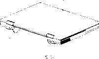
图3A为本发明的可携式电子装置的电池连接座的示意图;以及3A is a schematic view of the battery connection socket of the portable electronic device of the present invention; and
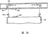
图3B为本发明的可携式电子装置的示意图。FIG. 3B is a schematic diagram of the portable electronic device of the present invention.
符号说明Symbol Description
1 本体1 body
11 固定部11 Fixed part
2 电池连接座2 battery connector
21 枢轴21 Pivot
22 长边22 long side
23 侧边23 side
24 开孔24 openings
4 角度控制机构4 Angle control mechanism
41 座体41 seat body
42 定位柱42 Positioning column
43 弹性元件43 elastic element
B 电池B battery
E1 电连接端口E1 electrical connection port
E1’ 相对电连接端口E1’ relative electrical connection port
F 软性电路板(Flexible Printed Circuit Board)F Flexible Printed Circuit Board
F1 第一卡合部F1 first engaging part
F1’ 第一相对卡合部F1' The first relative engaging part
F2 第二卡合部F2 Second engaging part
F2’ 第二相对卡合部F2' The second relative engaging part
H1 H2 H3定位孔H1 H2 H3 positioning hole
L1 第一接合部L1 first junction
L1’ 第二接合部L1’ second junction
M 印刷电路板(Printed Circuit Board)M Printed Circuit Board
具体实施方式Detailed ways
以下以具体的实施例,对本发明揭示的形态内容加以详细说明。The form and content disclosed by the present invention will be described in detail below with specific examples.
图1A-图1E为本发明的可携式电子装置的示意图(为方便及简化起见,以下将以笔记型计算机为例说明本发明),本发明的可携式电子装置主要包括一本体1、一电池连接座2以及一电池B,电池连接座2枢接于本体1,而电池B以可拆卸地方式与电池连接座2连接。1A-FIG. 1E are schematic diagrams of the portable electronic device of the present invention (for convenience and simplification, the present invention will be described below with a notebook computer as an example), the portable electronic device of the present invention mainly includes a
电池连接座2可于一第一位置(如第1A图所示)以及一第二位置(如第1B图所示)之间转动,当电池连接座2位于第一位置时,处于收纳状态,意即,电池连接座2收纳于本体1中;而当电池连接座2相对于本体1旋转而突出于本体1时,处于使用状态,此时电池连接座与本体成一角度,可支撑本体1,亦即,可通过电池连接座2支撑本发明的可携式电子装置。The
本体1中设置有印刷电路板(例如主机板)M,并具有一容纳部,通过连接于电池连接座2的软性电路板F可将电池B电连接至印刷电路板M。The
在将电池B装入容纳部,并与电池连接座2连接之后,当电池连接座2位于第一位置时,电池连接座2及电池B收纳于本体1中,而当电池连接座2相对于本体1旋转而突出于本体1时,电池连接座2及电池B可共同支撑本体1,即可通过电池连接座2及电池B支撑本发明的可携式电子装置。After the battery B is loaded into the accommodating part and connected with the
换句话说,如图1C所示,当电池B脱离电池连接座2时,本发明的可携式电子装置可以单独通过电池连接座2所支撑;又如图1D所示,当电池B与电池连接座2连接时,本发明的可携式电子装置可以由电池连接座2及电池B所共同支撑。In other words, as shown in Figure 1C, when the battery B is separated from the
再请参见图1E,图1E是由本发明的可携式电子装置的底侧观之,电池连接座2上设置有一第一接合部L1,而电池B上则设置有一第二接合部L1’,因此,当电池B连接至电池连接座2时,第一接合部L1与第二接合部L1’相接合,用以将电池B连接于电池连接座2上。举例来说,电池连接座2的第一接合部L1可以为一凸肋,而电池B的第二接合部L1’为一滑槽,当电池B置入电池连接座2时,凸肋可滑动地容置于滑槽中,并限制电池B不会自电池连接座2轻易脱离。或者,也可将第一接合部L1设计为一滑槽,而第二接合部L1’设计为一凸肋,也可达到相同功能。Please refer to FIG. 1E again. FIG. 1E is viewed from the bottom side of the portable electronic device of the present invention. The
又或者,第一接合部L1可以为一孔洞或一卡勾,第二接合部L1’为一插销或一卡扣,通过将插销插入孔洞或是卡勾连接卡扣,使电池固接于电池连接座。Alternatively, the first joint part L1 can be a hole or a hook, and the second joint part L1' can be a pin or a buckle. By inserting the pin into the hole or connecting the buckle with the hook, the battery is fixed to the battery. Connecting seat.
请参见图2A,同样由本发明的可携式电子装置的底侧观之,电池连接座2通过枢轴21而枢接于本体1的固定部11上。另外,在本体1上邻近于电池连接座2处更设置有角度控制机构4,用以固定电池连接座2相对于本体1所旋转的角度。角度控制机构4包括一座体41、一定位柱42及一弹性元件43,座体41设置于本体1上,定位柱42可活动地设置于座体41,而弹性元件43则穿设于定位柱42上,又,在电池连接座2上设置有多个定位孔H1、H2、H3,当电池连接座2相对于本体1而转动时,定位柱42通过弹性元件43所提供的弹性恢复力而选择性地卡合于多个定位孔H1、H2、H3的其中一者。举例来说,当电池连接座2位于第一位置时,定位柱42卡合于定位孔H1,当电池连接座2位于第二位置时,定位柱42卡合于定位孔H3,而当电池连接座2位于一中间位置时,定位柱42卡合于定位孔H2。由此,可固定电池连接座2相对于本体1所旋转的角度。在上述中的弹性元件43例如为一弹簧。又,为了使电池连接座2相对于本体1所旋转的角度更有变化,可通过增加电池连接座2上的定位孔的数量而达成。Please refer to FIG. 2A , also viewed from the bottom side of the portable electronic device of the present invention, the
另外,在本体上1更设置有第一卡合部F1,而电池连接座2设置有第一相对卡合部F1’,当第一卡合部F1与第一相对卡合部F1’互相卡合时,则可使电池连接座2固定于本体1。更详而言之,请参见图2B,当电池B置入电池连接座2时,电池连接座2的第一接合部L1与电池B的第二接合部L1’相接合,而电池连接座2的第一接合部L1上设置有第一相对卡合部F1’,因此,当移动第一卡合部F1使第一卡合部F1与第一相对卡合部F1’互相卡合时,可固定住电池连接座2,用以限制电池连接座2相对于本体1的转动。在上述中,第一卡合部F1例如为一突块,而第一相对卡合部F1’例如为一孔洞。In addition, the
再请参见图3A及图3B,说明电池连接座2。电池连接座2大体上呈U字型设置于容纳部的周围,具有一长边22以及两侧边23。上述的枢轴21沿一轴向延伸,而长边22与轴向平行;上述的第一接合部L1可分别设置于两侧边23的内侧,用以与第二接合部L1’接合;上述的第一相对卡合部F1’也可分别设置于两侧边23的外侧,用以与第一卡合部F1相卡合;上述的多个定位孔H1、H2、H3可形成于其中一侧边23或两侧边23上,用以与相对应的定位柱42相卡合。Referring to FIG. 3A and FIG. 3B again, the
又,在电池连接座2的长边22上设置有电连接端口E1,当电池B置入电池连接座2时,电连接端口E1与电池B上的相对电连接端口E1’电连接,再透过如图1A所示的连接于电池连接座2的软性电路板F,将电池B电连接至印刷电路板M。Also, an electrical connection port E1 is provided on the
另外,在电池连接座2的长边22上更设置有第二卡合部F2,而电池B设置有第二相对卡合部F2’,当第二卡合部F2与第二相对卡合部F2’互相卡合时,则可连接电池B连接于电池连接座2上。更详而言之,请参见图3B,当电池B置入电池连接座2后,电池B的第二相对卡合部F2’穿过电池连接座2上的开孔24,当移动第二卡合部F2使第二卡合部F2与第二相对卡合部F2’卡合时,则可将电池B连接于电池连接座2上,限制电池B不会自电池连接座2轻易脱离。在上述中,第二卡合部F2例如为一卡勾,而第二相对卡合部F2’例如为一卡扣。In addition, a second engaging portion F2 is further provided on the
综上所述,本发明所揭露的可携式电子装置,利用可相对于本体旋转而突出的电池连接座,可轻易的支撑可携式电子装置并改变可携式电子装置放置于一平面上的角度,因而可提高可携式电子装置于使用上的便利性。To sum up, the portable electronic device disclosed in the present invention can easily support the portable electronic device and change the portable electronic device to be placed on a plane by using the protruding battery connection base that can rotate relative to the main body. Therefore, the convenience of using the portable electronic device can be improved.
虽然结合以上较佳实施例揭露了本发明,然而其并非用以限定本发明,任何熟悉此项技术者,在不脱离本发明的精神和范围内,仍可作些许的更动与润饰,因此本发明的保护范围应以附上的权利要求所界定的为准。Although the present invention has been disclosed in combination with the above preferred embodiments, it is not intended to limit the present invention, and any person skilled in the art can still make some changes and modifications without departing from the spirit and scope of the present invention, so The scope of protection of the present invention should be defined by the appended claims.
Claims (17)
Priority Applications (1)
| Application Number | Priority Date | Filing Date | Title |
|---|---|---|---|
| CN 200610075595CN101059709A (en) | 2006-04-19 | 2006-04-19 | Portable electronic device |
Applications Claiming Priority (1)
| Application Number | Priority Date | Filing Date | Title |
|---|---|---|---|
| CN 200610075595CN101059709A (en) | 2006-04-19 | 2006-04-19 | Portable electronic device |
Publications (1)
| Publication Number | Publication Date |
|---|---|
| CN101059709Atrue CN101059709A (en) | 2007-10-24 |
Family
ID=38865851
Family Applications (1)
| Application Number | Title | Priority Date | Filing Date |
|---|---|---|---|
| CN 200610075595PendingCN101059709A (en) | 2006-04-19 | 2006-04-19 | Portable electronic device |
Country Status (1)
| Country | Link |
|---|---|
| CN (1) | CN101059709A (en) |
Cited By (3)
| Publication number | Priority date | Publication date | Assignee | Title |
|---|---|---|---|---|
| CN101652038A (en)* | 2008-08-15 | 2010-02-17 | 鸿富锦精密工业(深圳)有限公司 | Electronic equipment and switch device |
| CN103135674A (en)* | 2011-11-29 | 2013-06-05 | 英业达股份有限公司 | Electronic device |
| CN107015608A (en)* | 2017-04-24 | 2017-08-04 | 郑州云海信息技术有限公司 | A server chassis |
- 2006
- 2006-04-19CNCN 200610075595patent/CN101059709A/enactivePending
Cited By (5)
| Publication number | Priority date | Publication date | Assignee | Title |
|---|---|---|---|---|
| CN101652038A (en)* | 2008-08-15 | 2010-02-17 | 鸿富锦精密工业(深圳)有限公司 | Electronic equipment and switch device |
| CN101652038B (en)* | 2008-08-15 | 2013-04-24 | 鸿富锦精密工业(深圳)有限公司 | Electronic equipment and switch device |
| CN103135674A (en)* | 2011-11-29 | 2013-06-05 | 英业达股份有限公司 | Electronic device |
| CN103135674B (en)* | 2011-11-29 | 2016-05-25 | 英业达股份有限公司 | electronic device |
| CN107015608A (en)* | 2017-04-24 | 2017-08-04 | 郑州云海信息技术有限公司 | A server chassis |
Similar Documents
| Publication | Publication Date | Title |
|---|---|---|
| CN102480892B (en) | Chip card fixing mechanism and portable electronic device with fixing mechanism | |
| TWI401378B (en) | Portable electronic device | |
| US8387938B2 (en) | Electronic device holder | |
| US8292671B2 (en) | Connector | |
| US20120044624A1 (en) | Handle assembly for a portable electronic device | |
| CN104344184A (en) | Portable foldable cradle | |
| CN1703141A (en) | Hinge device and electronic equipment using the same | |
| CN1619460A (en) | electronic device with display | |
| CN1976363A (en) | Portable terminal with hinge device including two axes of rotation | |
| US20140118899A1 (en) | Electronic device and linkage mechanism thereof | |
| CN102606855A (en) | Base and electronic equipment assembly using base | |
| CN102915081A (en) | Portable electronic device and its connection port | |
| CN1204475C (en) | Notebook-type computer | |
| CN1976568A (en) | Information processing apparatus | |
| US8787010B2 (en) | Information processing apparatus | |
| CN101059709A (en) | Portable electronic device | |
| CN102969598B (en) | Connecting module and machine body applying same | |
| CN1525274A (en) | An electronic device having a latch that locks two parts in a closed position and is operable to open | |
| CN2609043Y (en) | Notebook computer on desk | |
| CN102693682A (en) | Display and electronic device with same | |
| TW201238444A (en) | Mounting apparatus for disk drive | |
| CN219420754U (en) | Card holds in palm and electronic equipment | |
| CN2843002Y (en) | Electronic equipment with clamping close device | |
| CN2490691Y (en) | Portable keyboard device | |
| CN2600686Y (en) | Electronic equipment with back support device |
Legal Events
| Date | Code | Title | Description |
|---|---|---|---|
| C06 | Publication | ||
| PB01 | Publication | ||
| C10 | Entry into substantive examination | ||
| SE01 | Entry into force of request for substantive examination | ||
| C02 | Deemed withdrawal of patent application after publication (patent law 2001) | ||
| WD01 | Invention patent application deemed withdrawn after publication |