CN101057370B - Luneberg dielectric lens and manufacturing method thereof - Google Patents
Luneberg dielectric lens and manufacturing method thereofDownload PDFInfo
- Publication number
- CN101057370B CN101057370BCN2005800384157ACN200580038415ACN101057370BCN 101057370 BCN101057370 BCN 101057370BCN 2005800384157 ACN2005800384157 ACN 2005800384157ACN 200580038415 ACN200580038415 ACN 200580038415ACN 101057370 BCN101057370 BCN 101057370B
- Authority
- CN
- China
- Prior art keywords
- layer
- dome
- expanded beads
- ceramic
- shaped
- Prior art date
- Legal status (The legal status is an assumption and is not a legal conclusion. Google has not performed a legal analysis and makes no representation as to the accuracy of the status listed.)
- Expired - Fee Related
Links
Images


Classifications
- C—CHEMISTRY; METALLURGY
- C04—CEMENTS; CONCRETE; ARTIFICIAL STONE; CERAMICS; REFRACTORIES
- C04B—LIME, MAGNESIA; SLAG; CEMENTS; COMPOSITIONS THEREOF, e.g. MORTARS, CONCRETE OR LIKE BUILDING MATERIALS; ARTIFICIAL STONE; CERAMICS; REFRACTORIES; TREATMENT OF NATURAL STONE
- C04B38/00—Porous mortars, concrete, artificial stone or ceramic ware; Preparation thereof
- C04B38/06—Porous mortars, concrete, artificial stone or ceramic ware; Preparation thereof by burning-out added substances by burning natural expanding materials or by sublimating or melting out added substances
- H—ELECTRICITY
- H01—ELECTRIC ELEMENTS
- H01Q—ANTENNAS, i.e. RADIO AERIALS
- H01Q15/00—Devices for reflection, refraction, diffraction or polarisation of waves radiated from an antenna, e.g. quasi-optical devices
- H01Q15/02—Refracting or diffracting devices, e.g. lens, prism
- H01Q15/08—Refracting or diffracting devices, e.g. lens, prism formed of solid dielectric material
- H—ELECTRICITY
- H01—ELECTRIC ELEMENTS
- H01Q—ANTENNAS, i.e. RADIO AERIALS
- H01Q19/00—Combinations of primary active antenna elements and units with secondary devices, e.g. with quasi-optical devices, for giving the antenna a desired directional characteristic
- H01Q19/06—Combinations of primary active antenna elements and units with secondary devices, e.g. with quasi-optical devices, for giving the antenna a desired directional characteristic using refracting or diffracting devices, e.g. lens
- H01Q19/062—Combinations of primary active antenna elements and units with secondary devices, e.g. with quasi-optical devices, for giving the antenna a desired directional characteristic using refracting or diffracting devices, e.g. lens for focusing
- C—CHEMISTRY; METALLURGY
- C04—CEMENTS; CONCRETE; ARTIFICIAL STONE; CERAMICS; REFRACTORIES
- C04B—LIME, MAGNESIA; SLAG; CEMENTS; COMPOSITIONS THEREOF, e.g. MORTARS, CONCRETE OR LIKE BUILDING MATERIALS; ARTIFICIAL STONE; CERAMICS; REFRACTORIES; TREATMENT OF NATURAL STONE
- C04B2111/00—Mortars, concrete or artificial stone or mixtures to prepare them, characterised by specific function, property or use
- C04B2111/00474—Uses not provided for elsewhere in C04B2111/00
- C04B2111/00939—Uses not provided for elsewhere in C04B2111/00 for the fabrication of moulds or cores
Landscapes
- Chemical & Material Sciences (AREA)
- Engineering & Computer Science (AREA)
- Ceramic Engineering (AREA)
- Materials Engineering (AREA)
- Structural Engineering (AREA)
- Organic Chemistry (AREA)
- Aerials With Secondary Devices (AREA)
Abstract
Description
Translated fromChinese技术领域technical field
本发明涉及介电透镜(dielectric lens)。更具体地,本发明涉及半球形Luneberg介电透镜,其中半球形含陶瓷的泡沫中心层和多个半球形圆顶状的泡沫层被同心堆叠,并且其中每层中每单位体积的陶瓷含量得到调节。本发明也涉及制备用于制造介电透镜的一系列泡沫模制品的方法。 The present invention relates to dielectric lenses. More specifically, the present invention relates to a hemispherical Luneberg dielectric lens in which a hemispherical ceramic-containing foam core layer and a plurality of hemispherical dome-shaped foam layers are concentrically stacked, and wherein the ceramic content per unit volume in each layer is obtained adjust. The invention also relates to a process for the preparation of a series of foam moldings for the manufacture of dielectric lenses. the
背景技术Background technique
近年来,随着信息通讯技术的显著发展和信息量的增加,要求信号信息的传递更加精确和更加快速。同时,高频带的使用正迅速增加。尤其是,已经开始全规模使用高于1GHz的频带,特别是10至20GHz之间的频带。因此,在卫星广播和卫星通信中,期望开发一种利用Luneberg透镜天线(Luneberg lens attenna)发送和接收无线电波的方法作为使用抛物形天线的传统方法的替代。 In recent years, with the remarkable development of information and communication technology and the increase of information volume, the transmission of signal information is required to be more accurate and faster. At the same time, the use of high frequency bands is increasing rapidly. In particular, frequency bands above 1 GHz, especially between 10 and 20 GHz, have been used on a full scale. Therefore, in satellite broadcasting and satellite communication, it is expected to develop a method of transmitting and receiving radio waves using a Luneberg lens antenna (Luneberg lens antenna) as an alternative to the conventional method using a parabolic antenna. the
在使用抛物形天线的卫星广播和卫星通信的传统系统中,将同步卫星与朝向固定方向的抛物形天线一起使用,来发送和接收无线电波。用此系统,为了向多个卫星发送无线电波并且从该多个卫星接收无线电波,必须根据目标卫星的位置改变天线的朝向,或者使用多个抛物形天线。相反,当多个馈给信号(feed)位于天线盖上的Luneberg透镜的焦点位置(focal position)上时,Luneberg透镜天线(安装有Luneberg介电透镜的球形或半球形天线)能够向多个静止卫星发送无线电波并且从该多个静止卫星接收无线电波。此外,当作为通信目标的卫星或者天线如同近地轨道卫星(low earth orbit satellite,LEO)的情况移动时,在抛物形天线的情况下,整个天线必须跟踪该目标;然而,在Luneberg透镜天线的情况下,仅其小组件例如接收器或发送器必须跟踪该目标。因此,Luneberg透镜天线不需要大的驱动系统,并且也适合作为移动体的天线。根据使用Luneberg透镜天线的方法,能够在每一居所(residence)使用一个天线发送和接收大量信息。也即,Luneberg透镜天线也适合在多频道广播的时代作为接收电视广播的天线。 In conventional systems of satellite broadcasting and satellite communication using a parabolic antenna, a geostationary satellite is used with a parabolic antenna oriented in a fixed direction to transmit and receive radio waves. With this system, in order to transmit radio waves to and receive radio waves from a plurality of satellites, it is necessary to change the orientation of the antenna according to the position of the target satellite, or to use a plurality of parabolic antennas. Conversely, a Luneberg lens antenna (a spherical or hemispherical antenna fitted with a Luneberg dielectric lens) is capable of feeding multiple stationary signals when multiple feeds are located at the focal position of the Luneberg lens on the antenna cover. Satellites transmit radio waves and receive radio waves from the plurality of geostationary satellites. In addition, when the satellite or antenna that is the communication target moves as in the case of a low earth orbit satellite (LEO), in the case of a parabolic antenna, the entire antenna must track the target; however, in the case of a Luneberg lens antenna In this case, only its widgets such as receivers or transmitters must track the target. Therefore, the Luneberg lens antenna does not require a large drive system, and is also suitable as an antenna for a moving body. According to the method using the Luneberg lens antenna, it is possible to transmit and receive a large amount of information using one antenna per residence. That is, the Luneberg lens antenna is also suitable as an antenna for receiving television broadcasts in the era of multi-channel broadcasting. the
Luneberg透镜天线安装有Luneberg介电透镜,该介电透镜具有会聚和聚焦无线电波的功能。用于Luneberg介电透镜的材料必须具有优良的介电性质(例如均匀的介电常数和低的介电损耗角正切),从而处理日益增加的信息量,也即高频无线电波。此外,由于天线经常被安装在每个居所的屋顶上,所以从安装工作的效率和安全的观点来看,材料的尺寸应该小,以及材料的重量应该轻。 The Luneberg lens antenna is equipped with a Luneberg dielectric lens that has the function of converging and focusing radio waves. Materials used in Luneberg dielectric lenses must have excellent dielectric properties (eg, uniform permittivity and low dielectric loss tangent) to handle the ever-increasing amount of information, ie, high-frequency radio waves. In addition, since the antenna is often installed on the roof of each residence, the size of the material should be small and the weight of the material should be light from the viewpoint of efficiency and safety of the installation work. the
Luneberg介电透镜具有球形或半球形的形状,并且包括多个同心堆叠的具有不同介电常数的层,从而介电常数理论上从2至1变化,并且最内的中心层的介电常数约为2,最外层的介电常数约为1。因此,理论上,如此设计Luneberg介电透镜,使得介电常数εr根据以下方程(1)从中心(r=0)到表面(r=R)变化: A Luneberg dielectric lens has a spherical or hemispherical shape and consists of a number of concentrically stacked layers with different dielectric constants, whereby the dielectric constant theoretically varies from 2 to 1, and the innermost central layer has a dielectric constant of about is 2, and the dielectric constant of the outermost layer is about 1. Therefore, in theory, a Luneberg dielectric lens is designed such that the permittivity εr varies from the center (r=0) to the surface (r=R) according to the following equation (1):
εr=2-(r/R)2 (1) εr =2-(r/R)2 (1)
其中,εr、R和r分别表示介电常数、透镜的半径和测量点处的半径。每层的介电常数参考由以上方程(1)确定的值来确定。 Among them, εr , R and r represent the permittivity, the radius of the lens and the radius at the measurement point, respectively. The dielectric constant of each layer is determined with reference to the value determined by equation (1) above.
但是,实际上,由于难以获得介电常数根据由方程(1)给出的理想曲线连续变化的模制产品,所以Luneberg介电透镜是通过结合多个具有不同介电常数的离散的层制造的。美国专利申请公开第20040029985号中公开了一种Luneberg型的介电透镜。该介电透镜为球形,其具有核和多个中空球形壳,该核和多个中空球形壳具有不同的介电常数,该球形壳包围该核并且彼此同心重叠以形成同心球。该核和壳分别由含有无机介电填料的合成树脂的泡沫制成。由于该介电透镜重量轻,所以它能够保证可使用性和安装工作的安全。但是,使用美国专利申请公开第20040029985号中公开的介电透镜的天线不足以满足实际使用的性能,例如天线增益。 However, in practice, since it is difficult to obtain a molded product in which the dielectric constant varies continuously according to the ideal curve given by equation (1), Luneberg dielectric lenses are fabricated by combining a plurality of discrete layers with different dielectric constants . US Patent Application Publication No. 20040029985 discloses a Luneberg type dielectric lens. The dielectric lens is spherical with a core and a plurality of hollow spherical shells having different dielectric constants, the spherical shells surrounding the core and concentrically overlapping each other to form concentric spheres. The core and the shell are each made of a foam of synthetic resin containing inorganic dielectric fillers. Due to its light weight, the dielectric lens ensures workability and safety for installation work. However, the antenna using the dielectric lens disclosed in US Patent Application Publication No. 20040029985 is insufficient for practical performance such as antenna gain. the
发明内容Contents of the invention
因此,本发明的目的是提供一种Luneberg介电透镜,其具有优良的实际使用的天线特性,例如天线增益。 It is therefore an object of the present invention to provide a Luneberg dielectric lens which is excellent in antenna characteristics for practical use, such as antenna gain. the
本发明的另一目的是提供能够制造一系列泡沫模制品(foam moldings)的方法,该泡沫模制品具有变化的每单位体积陶瓷含量,并适合用于制造介电透镜。 Another object of the present invention is to provide a process enabling the manufacture of a series of foam moldings with varying ceramic content per unit volume, suitable for use in the manufacture of dielectric lenses. the
本发明的一方面提供半球形介电透镜,其包括: One aspect of the present invention provides a hemispherical dielectric lens comprising:
半球形中心层,其具有半球形外表面;和 a hemispherical central layer having a hemispherical outer surface; and
多个半球形圆顶状层(hemisperical dome-shaped layer),每层具有同心的半球形内表面和外表面,所述中心层外表面和圆顶状层的外表面具有不同的直径,所述圆顶状层的内表面具有不同的直径, a plurality of hemisperical dome-shaped layers, each layer having concentric hemispherical inner and outer surfaces, the outer surface of the central layer and the outer surface of the dome-shaped layer having different diameters, the The inner surface of the dome-shaped layer has different diameters,
所述中心层和圆顶状层被连续地彼此同心装配,并被整合成半球形, The central layer and the dome-shaped layer are successively fitted concentrically with each other and are integrated into a hemisphere,
所述中心层是含陶瓷的热塑性树脂膨胀珠(thermoplastic resin expanded beads)的泡沫模制品, The central layer is a foam molding containing ceramic thermoplastic resin expanded beads,
所述圆顶状层中每层均是热塑性树脂膨胀珠的泡沫模制品,其含有0至80重量%陶瓷, Each of said dome-shaped layers is a foam molding of thermoplastic resin expanded beads containing 0 to 80% by weight of ceramics,
其中,每单位体积的所述中心层和圆顶状层的陶瓷含量从所述中心层至最外圆顶状层减小,并且 wherein the ceramic content per unit volume of said central layer and dome-shaped layer decreases from said central layer to the outermost dome-shaped layer, and
其中所述中心层和圆顶状层中每层的表观密度(apparent density)的标准偏差为0.07g/cm3以下。 Wherein the standard deviation of the apparent density of each of the central layer and the dome-shaped layer is 0.07 g/cm3 or less.
另一方面,本发明提供球形介电透镜,其包括: In another aspect, the present invention provides a spherical dielectric lens comprising:
球形核,其具有球形外表面;和 a spherical core having a spherical outer surface; and
多个中空球形壳,每壳具有同心的球形内表面和外表面,所述核的外表面和壳的外表面具有不同的直径,并且所述壳的内表面具有不同的直径, a plurality of hollow spherical shells, each having concentric spherical inner and outer surfaces, the outer surface of the core and the outer surface of the shell having different diameters, and the inner surface of the shells having a different diameter,
所述核和壳被同心放置,并被整合成球形, The core and shell are concentrically placed and integrated into a spherical shape,
所述核是含陶瓷的热塑性树脂膨胀珠的泡沫模制品, The core is a foam molding containing ceramic expanded beads of thermoplastic resin,
每个所述壳都是含0至80重量%陶瓷的热塑性树脂膨胀珠的泡沫模制品, Each of said shells is a foam molding of expanded beads of thermoplastic resin containing 0 to 80% by weight ceramic,
其中,每单位体积的所述核和壳的陶瓷含量从所述核至最外的壳减小,并且 wherein the ceramic content per unit volume of said core and shell decreases from said core to the outermost shell, and
其中每个所述核和壳的表观密度(apparent density)的标准偏差为0.07g/cm3以下。 wherein the standard deviation of apparent density of each of the core and shell is 0.07 g/cm3 or less.
本发明也提供制备用于制造介电透镜的一系列泡沫模制品的方法,该泡沫模制品具有变化的每单位体积陶瓷含量,该制造方法包括如下步骤: The present invention also provides a method for preparing a series of foam moldings for the manufacture of dielectric lenses, the foam moldings having varying ceramic contents per unit volume, the manufacturing method comprising the steps of:
提供含陶瓷的树脂粒子,每树脂粒子具有相同重量百分比含量的陶瓷; Provide ceramic-containing resin particles, each resin particle has ceramics in the same weight percentage content;
将树脂粒子分成P组,以不同的膨胀比(expansion ratio)发泡(foaming)和膨胀(expanding)各组的树脂粒子,获得P组具有不同表观密度的膨胀珠; The resin particle is divided into P group, with different expansion ratio (expansion ratio) foaming (foaming) and the resin particle of expansion (expanding) each group, obtains the expansion bead that P group has different apparent densities;
从P组膨胀珠中选择Q组(1≤Q≤P)膨胀珠,并使Q组膨胀珠经过表 观密度调节处理,获得R组(R≥1)处理过的膨胀珠,从而总共获得(P-Q+R)组具有不同表观密度的处理和未处理的膨胀珠,它们重量的标准偏差为0.5mg以下,并且其表观密度的标准偏差为0.1g/cm3以下;和 Select Q group (1≤Q≤P) expansion beads from the P group expansion beads, and make the Q group expansion beads undergo the apparent density adjustment process to obtain the R group (R≥1) processed expansion beads, thus obtaining a total of ( P-Q+R) groups have treated and untreated expanded beads of different apparent densities, the standard deviation of their weights is 0.5 mg or less, and the standard deviation of their apparent densities is 0.1 g/cm3 or less; and
在具有不同尺寸模腔的不同模具中模制(P-Q+R)-组膨胀珠中的每组,获得(P-Q+R)-种模制品,该模制品的每单位体积具有不同重量的陶瓷。 Each of the (P-Q+R)-groups of expanded beads is molded in different molds with different-sized mold cavities to obtain (P-Q+R)-type molded articles having different weight of ceramic. the
附图说明Description of drawings
当根据附图考虑时,本发明的其它目的、特征和优点将由以下本发明优选实施方式的详细说明变得明显,附图中: Other objects, features and advantages of the present invention will become apparent from the following detailed description of preferred embodiments of the invention when considered in light of the accompanying drawings, in which:
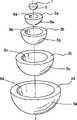
图1是图解地说明本发明介电透镜的实施方式的透视图; Figure 1 is a perspective view diagrammatically illustrating an embodiment of a dielectric lens of the present invention;
图2是图1的介电透镜除去盖(cover)的透视分解图; Figure 2 is a perspective exploded view of the dielectric lens of Figure 1 with the cover removed;
图3示出了聚丙烯树脂膨胀珠的模制品的初次DSC曲线图的例子; Figure 3 shows an example of the initial DSC curve graph of a molded product of polypropylene resin expanded beads;
图4示出了用于测量其熔点和熔融完成温度(melt completion temperature)的聚丙烯树脂二次DSC曲线的图的例子; Figure 4 shows an example of a plot of a quadratic DSC curve of a polypropylene resin used to measure its melting point and melt completion temperature;
图5(a)是图解地说明用于测量膨胀珠的比重的设备的正视图(elevational view); Fig. 5 (a) is the front view (elevational view) that schematically illustrates the equipment for measuring the specific gravity of expanded beads;
图5(b)是图5(a)的侧视图; Fig. 5 (b) is the side view of Fig. 5 (a);
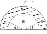
图6(a)是圆顶状层的平面图,其示出了从圆顶状层上切掉样品,以用来测量它们的介电常数的取样位置; Fig. 6 (a) is the plan view of dome-shaped layer, and it has shown cut away sample from dome-shaped layer, to be used for the sampling position of measuring their dielectric constant;
图6(b)是沿着图6(a)中的线VIb-VIb的剖视图;和 Figure 6(b) is a cross-sectional view along line VIb-VIb in Figure 6(a); and
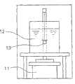
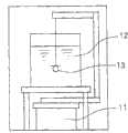
图7是用于测量Luneberg天线的天线增益的系统的说明性示意图。 7 is an explanatory schematic diagram of a system for measuring antenna gain of a Luneberg antenna. the
具体实施方式Detailed ways
本发明的半球形介电透镜包括半球形中心(或核)层和同心堆叠在中心层上的多个半球形圆顶状层(或壳)。优选地,中心层和邻近的圆顶状层之间的间隙尽可能地小,并且邻近的两个圆顶状层之间的间隙也尽可能地小。换句话说,介电透镜的每邻近的两层理想地设置为彼此接触。当所述缝隙大时,无线电波通过空气-层界面时会被不必要地反射或折射,这导致天线增益的减少或旁瓣(sidelobe)的增加。 The hemispherical dielectric lens of the present invention includes a hemispherical central (or core) layer and a plurality of hemispherical dome-shaped layers (or shells) stacked concentrically on the central layer. Preferably, the gap between the central layer and the adjacent dome-shaped layer is as small as possible, and the gap between two adjacent dome-shaped layers is also as small as possible. In other words, every adjacent two layers of the dielectric lens are ideally disposed in contact with each other. When the gap is large, radio waves are unnecessarily reflected or refracted when passing through the air-layer interface, which results in a decrease in antenna gain or an increase in sidelobe. the
当本发明两个类似的半球形介电透镜结合形成球时,可获得球形介电透镜。在这种情况下,可以使用单个球形核作为球形介电透镜的最内层, 而不使用两个半球形中心层。这种球形介电透镜当然在本发明的范围内。 When two similar hemispherical dielectric lenses of the present invention are combined to form a sphere, a spherical dielectric lens can be obtained. In this case, a single spherical core can be used as the innermost layer of the spherical dielectric lens instead of two hemispherical central layers. Such spherical dielectric lenses are of course within the scope of the present invention. the
图1描述本发明的半球形介电透镜的例子。如图2所示(图2是图1的介电透镜的分解图),介电透镜具有:半球形中心层1,半球形中心层1具有半球形外表面5;以及四个半球形圆顶状层2a、2b、2c和2d,其各具有半球形外表面5a、5b、5c和5d及半球形内表面6a、6b、6c和6d。每个圆顶状层2a、2b、2c和2d的外表面与其内表面是同心的。外表面5、5a、5b、5c和5d的直径彼此不同,内表面6a、6b、6c和6d的直径彼此不同。通过连续同心地将中心层1和圆顶状层2a、2b、2c和2d彼此装配,从而整合它们,可获得图l所示的半球形透镜。在图1中,3所指的是半球形中空盖,其具有半球形透镜被装配在其内的半球形凹穴,并且其最外层2d与盖3的内表面紧密接触。盖可由合成树脂形成。通过将无线电波反射体(未示出)连接到该多层介电透镜的平扁表面上来形成Luneberg透镜天线。但是本发明不限于图1所示的实施方式。 Fig. 1 depicts an example of a hemispherical dielectric lens of the present invention. As shown in Figure 2 (Figure 2 is an exploded view of the dielectric lens of Figure 1), the dielectric lens has: a hemispherical
因为需要令人满意的天线性能和制造容易性,本发明的介电透镜优选具有约50至约4,000mm,更优选约50至约2,000mm,还更优选约120至约1,800mm,最优选约350至1,000mm的直径。圆顶状层的数目为至少2。圆顶状层的数目上限为约80。出于对由上述方程(1)表示的理想曲线更好近似的原因,圆顶状层的数目优选为至少4,更优选为至少7。随着圆顶状层的数目增加,空气-层界面增加的可能性增加,这有害地影响天线增益。此外,在透镜中,在从中心层到最外层的方向上,介电常数理论上从约2到约1变化。因此,当层数目大时,各层之间的介电常数差异必须极其小。因此,根据天线组件的制造条件,邻近层间的介电常数可能被颠倒,从而会降低天线性能。因此,圆顶状层的数目优选为40以下,更优选20以下。每个圆顶状层的厚度优选为10至80mm,更优选为15至50mm,最优选为15至30mm。 Because of the need for satisfactory antenna performance and ease of manufacture, the dielectric lens of the present invention preferably has a thickness of about 50 to about 4,000 mm, more preferably about 50 to about 2,000 mm, still more preferably about 120 to about 1,800 mm, most preferably about Diameters from 350 to 1,000mm. The number of dome-shaped layers is at least two. The upper limit to the number of domed layers is about 80. The number of dome-shaped layers is preferably at least 4, more preferably at least 7, for reasons of better approximation to the ideal curve represented by equation (1) above. As the number of domed layers increases, the likelihood of increased air-layer interfaces increases, which adversely affects antenna gain. Furthermore, in the lens, the dielectric constant theoretically varies from about 2 to about 1 in the direction from the center layer to the outermost layer. Therefore, when the number of layers is large, the difference in dielectric constant between the layers must be extremely small. Therefore, depending on the manufacturing conditions of the antenna assembly, the dielectric constant between adjacent layers may be reversed, thereby degrading the antenna performance. Therefore, the number of dome-shaped layers is preferably 40 or less, more preferably 20 or less. The thickness of each dome-shaped layer is preferably 10 to 80 mm, more preferably 15 to 50 mm, most preferably 15 to 30 mm. the
在本发明中,每个半球形中心层和半球形圆顶状层优选形成为整体(one piece)。但是为了制造的方便,可通过结合多个分别制造的组件(piece)来形成一层或多层。 In the present invention, each of the hemispherical center layer and the hemispherical dome-shaped layer is preferably formed as one piece. But for convenience of manufacture, one or more layers may be formed by combining a plurality of separately manufactured pieces. the
中心层是含陶瓷的热塑性树脂膨胀珠的泡沫模制品,而每个圆顶状层是热塑性树脂膨胀珠的泡沫模制品,并含有0至80重量%的陶瓷。泡沫模制品通过模内模制方法(in-mold molding method)制造,在该方法中,将根据 需要与陶瓷混合的热塑性树脂膨胀珠填充入模具中,并加热使它们熔融粘结到一起。通过对根据需要与陶瓷混合的热塑性树脂的树脂粒子进行发泡和膨胀,来制造膨胀珠(expanded bead)。 The center layer is a foam molding of thermoplastic resin expanded beads containing ceramics, and each dome-shaped layer is a foam molding of thermoplastic resin expanded beads and contains 0 to 80% by weight of ceramics. Foam molded articles are produced by an in-mold molding method in which expanded beads of thermoplastic resin mixed with ceramics as needed are filled into a mold and heated to fuse them together. Expanded beads are produced by foaming and expanding resin particles of thermoplastic resin mixed with ceramics as needed. the
用作泡沫模制品的基础树脂(base resin)的热塑性树脂可为聚烯烃树脂,例如低密度聚乙烯树脂、高密度聚乙烯树脂、线型低密度聚乙烯树脂、聚丙烯树脂、苯乙烯改性的聚丙烯树脂(可通过将苯乙烯接枝到聚丙烯树脂上获得);聚苯乙烯树脂、聚酯树脂或聚碳酸酯树脂。如果需要的话,这些树脂可以以它们中的两种或多种结合来使用,或与另一种聚合物结合来使用这些树脂。尤其是,出于膨胀珠的制备优点,例如调节其表观密度的容易程度的原因,优选使用聚烯烃树脂或聚苯乙烯树脂。因为具有优良的耐热性、机械强度和可加工性,聚丙烯树脂尤其优选用作基础树脂。 The thermoplastic resin used as the base resin of foam moldings may be polyolefin resins such as low-density polyethylene resins, high-density polyethylene resins, linear low-density polyethylene resins, polypropylene resins, styrene-modified Polypropylene resin (obtainable by grafting styrene to polypropylene resin); polystyrene resin, polyester resin or polycarbonate resin. These resins may be used in combination of two or more thereof, or these resins may be used in combination with another polymer, if desired. In particular, polyolefin resins or polystyrene resins are preferably used for reasons of production advantages of expanded beads, such as easiness of adjusting the apparent density thereof. Polypropylene resin is particularly preferably used as the base resin because of its excellent heat resistance, mechanical strength and workability. the
此处所用的术语“聚丙烯树脂”意图指丙烯的均聚物或丙烯与一种或多种共聚单体的共聚物,该共聚物具有至少70mol%,优选至少80mol%的丙烯单体单元含量。丙烯共聚物的例子包括丙烯-乙烯无规共聚物、丙烯-乙烯嵌段共聚物、丙烯-丁烯无规共聚物和丙烯-乙烯-丁烯无规三元共聚物。 The term "polypropylene resin" as used herein is intended to mean a homopolymer of propylene or a copolymer of propylene and one or more comonomers, the copolymer having a content of propylene monomer units of at least 70 mol%, preferably at least 80 mol% . Examples of propylene copolymers include propylene-ethylene random copolymers, propylene-ethylene block copolymers, propylene-butene random copolymers and propylene-ethylene-butene random terpolymers. the
用于中心层的泡沫模制品含有陶瓷,而用于圆顶状层的每个泡沫模制品含有0至80重量%的陶瓷。因为陶瓷含有在泡沫模制品中,所以可容易地调节其介电常数。虽然可通过控制泡沫模制品的密度来控制其介电常数,但是仅通过控制密度不容易制备具有1.4以上的介电常数的泡沫模制品。通过将陶瓷结合到泡沫模制品中,能够将泡沫模制品的介电常数设置在高于1.4的值。在本发明中,不仅通过调节泡沫模制品的密度,而且通过调节其陶瓷含量(重量%),来控制泡沫模制品的介电常数。 The foam moldings for the central layer contain ceramics, whereas the foam moldings for the dome-shaped layers contain 0 to 80% by weight of ceramics each. Since the ceramic is contained in the foam molding, its dielectric constant can be easily adjusted. Although the dielectric constant of a foam molding can be controlled by controlling its density, it is not easy to prepare a foam molding having a dielectric constant of 1.4 or more only by controlling the density. By incorporating ceramics into the foam moldings, it is possible to set the dielectric constant of the foam moldings at values higher than 1.4. In the present invention, the dielectric constant of the foam molding is controlled not only by adjusting the density of the foam molding but also by adjusting the ceramic content (% by weight) thereof. the
重要的是,用于中心层和圆顶状层的泡沫模制品的每单位体积陶瓷含量(g/cm3)从中心层至最外圆顶状层减小,以使介电常数基于以上理论方程(1)从最内中心层处约2的介电常数变化到最外层处约1的介电常数。泡沫模制品的每单位体积陶瓷含量(g/cm3)的理想分布可如下获得:例如,将预定量(重量%)的陶瓷结合到泡沫模制品中,并从中心层到最外层减小泡沫模制品的表观密度。在这种情况下,虽然泡沫模制品具有相同的每单位重量陶瓷含量(重量%),但是其每单位体积陶瓷含量(g/cm3)从中心层至最外层减小。接着可通过以各种不同的膨胀比来发泡和膨胀具有预定重量百分比含量陶瓷的相同树脂粒子(粒料),获得不同组的具有不同表观密度的膨胀珠, 并通过在不同模具中模制该不同组的膨胀珠,来获得一系列具有所需介电常数分布的泡沫模制品。因此,能够容易地控制泡沫模制品的介电常数,并且能够显著提高其制造效率。因此,优选使用1至7种,尤其是2至5种具有不同重量百分比含量的陶瓷的树脂粒子(树脂粒子的种类数不超过(X-1),其中X是指介电透镜的层数),来形成本发明的介电透镜。以不同的膨胀比发泡和膨胀每种树脂粒子,获得不同组的具有不同表观密度的膨胀珠,并且在各种不同的模具中模制,由所述不同组的膨胀珠获得介电透镜。 It is important that the ceramic content per unit volume (g/cm3 ) of the foam moldings for the center layer and the dome-shaped layer decrease from the center layer to the outermost dome-shaped layer so that the dielectric constant is based on the above theory Equation (1) varies from a dielectric constant of about 2 at the innermost center layer to a dielectric constant of about 1 at the outermost layer. A desired distribution of the ceramic content (g/cm3 ) per unit volume of the foam molding can be obtained by, for example, incorporating a predetermined amount (% by weight) of ceramic into the foam molding and decreasing from the center layer to the outermost layer Apparent density of foam moldings. In this case, although the foam molding has the same ceramic content per unit weight (% by weight), its ceramic content per unit volume (g/cm3 ) decreases from the center layer to the outermost layer. Then, different groups of expanded beads with different apparent densities can be obtained by foaming and expanding the same resin particles (pellets) with a predetermined weight percentage content of ceramics at various expansion ratios, and by molding in different molds The different sets of expanded beads are produced to obtain a series of foam moldings with the desired dielectric constant distribution. Therefore, the dielectric constant of the foam molding can be easily controlled, and its production efficiency can be significantly improved. Therefore, it is preferable to use 1 to 7 kinds, especially 2 to 5 kinds of resin particles of ceramics with different weight percent contents (the number of kinds of resin particles does not exceed (X-1), where X refers to the number of layers of the dielectric lens) , to form the dielectric lens of the present invention. Each resin particle is foamed and expanded at different expansion ratios to obtain different sets of expanded beads having different apparent densities, and molded in various different molds from which a dielectric lens is obtained .
本说明书和所附的权利要求中所用的“用于中心层和圆顶状层的泡沫模制品的每单位体积陶瓷含量(g/cm3)从中心层到最外圆顶状层减小”意图指每个圆顶状层的每单位体积陶瓷含量(g/cm3)基本上等于或小于它邻近的内层(中心层或圆顶状层)的每单位体积陶瓷含量,并且最外圆顶状层的每单位体积陶瓷含量(g/cm3)小于最内中心层的每单位体积陶瓷含量。在如图1所示的介电透镜的情况下,例如中心层1和圆顶状层2a、2b、2c和2d的每单位体积陶瓷含量A、B、C、D和E(g/cm3)分别应该为:B基本上等于或小于A,C基本上等于或小于B,D基本上等于或小于C,E基本上等于或小于D,并且E小于A。因此,例如以下条件在本发明的范围内: "The ceramic content (g/cm3 ) per unit volume of the foam molding for the central layer and the dome-shaped layer decreases from the central layer to the outermost dome-shaped layer" used in this specification and the appended claims It is intended to mean that the ceramic content per unit volume (g/cm3 ) of each dome-shaped layer is substantially equal to or less than the ceramic content per unit volume of its adjacent inner layer (central layer or dome-shaped layer), and the outermost circle The ceramic content per unit volume (g/cm3 ) of the top layer is smaller than that of the innermost central layer. In the case of a dielectric lens as shown in FIG. 1, for example, the ceramic contents A, B, C, D, and E per unit volume of the
A>B>C>D>E; A>B>C>D>E;
A>B>C>D≈E; A>B>C>D≈E;
A>B>C≈D≈E;和 A>B>C≈D≈E; and
A≈B>C>D>E A≈B>C>D>E
其中,符号≈表示“基本上等于”。但是A≈B≈C≈D≈E的条件不在本发明的范围内。如此处所用的,术语“基本上等于”意图指“等于”或“不比...大超过0.009g/cm3”。即,例如当D为0.100g/cm3,E为0.109g/cm3时,E被认为是基本上等于D,因此,此条件包含在本发明的范围内。 Wherein, the symbol ≈ means "substantially equal to". However, the condition of A≈B≈C≈D≈E is out of the scope of the present invention. As used herein, the term "substantially equal to" is intended to mean "equal to" or "no more than 0.009 g/cm3 ". That is, for example, when D is 0.100 g/cm3 and E is 0.109 g/cm3 , E is considered to be substantially equal to D, and therefore, this condition falls within the scope of the present invention.
优选的是,当将中心层和圆顶状层中每层的每单位体积陶瓷含量(g/cm3)每个精确到百分位(精确到0.01)时,每单位体积陶瓷含量(g/cm3)等于或小于它邻近的内层。还优选的是,当每单位体积陶瓷含量(g/cm3)精确到0.01时,该介电透镜具有至少三层具有不同的陶瓷含量/单位体积(g/cm3)的层(包括中心层)。还优选的是,该介电透镜没有这样邻近的三层或更多层,它们的陶瓷含量/单位体积(g/cm3)基本上相互相等。尤其优选的是,当每单位体积陶瓷含量精确到0.01时,每个中心层和圆顶状层的每单位体积陶瓷含量 (g/cm3)小于它邻近的内层。 Preferably, when the ceramic content per unit volume (g/cm3 ) of each layer in the center layer and the dome-shaped layer is each accurate to the percentile (accurate to 0.01), the ceramic content per unit volume (g/cm 3 ) cm3 ) equal to or smaller than its adjacent inner layer. It is also preferable thatthe dielectric lens has at least three layers (including the central layer ). It is also preferred that the dielectric lens has no adjacent three or more layers whose ceramic contents per unit volume (g/cm3 ) are substantially equal to each other. It is especially preferred that each of the central and dome-shaped layers have a smaller ceramic content per unit volume (g/cm3 ) than its adjacent inner layer when the ceramic content per unit volume is accurate to 0.01.
也优选的是,所述中心层和所述圆顶状层的表观密度从所述中心层到最外圆顶状层减小。本说明书和附加的权利要求中所用的“用于中心层和圆顶状层的泡沫模制品的表观密度(g/cm3)从中心层到最外圆顶状层减小”意图指每个圆顶状层的表观密度基本上等于或小于它邻近的内层(中心层或圆顶状层)的表观密度(g/cm3),并且最外圆顶状层的表观密度(g/cm3)小于最内中心层的表观密度(g/cm3)。如此处所用的,术语“基本上等于”意图指“等于”或“不比...大超过0.030g/cm3”。优选的是,当将中心层和圆顶状层中每层的表观密度(g/cm3)精确到0.01时,每个表观密度(g/cm3)等于或小于它邻近的内层。尤其优选的是,当将中心层和圆顶状层中每层的表观密度(g/cm3)精确到0.01时,每个表观密度(g/cm3)小于它邻近的内层。 It is also preferred that the apparent density of the central layer and the dome-shaped layer decreases from the central layer to the outermost dome-shaped layer. "The apparent density (g/cm3 ) of the foam moldings for the central layer and the dome-shaped layer decreases from the central layer to the outermost dome-shaped layer" as used in this specification and the appended claims is intended to mean that each The apparent density of a dome-shaped layer is substantially equal to or less than the apparent density (g/cm3 ) of its adjacent inner layer (central layer or dome-shaped layer), and the apparent density of the outermost dome-shaped layer (g/cm3 ) is less than the apparent density (g/cm3 ) of the innermost central layer. As used herein, the term "substantially equal to" is intended to mean "equal to" or "no more than 0.030 g/cm3 ". It is preferable that each apparent density (g/cm3 ) of the central layer and the dome-shaped layer is equal to or smaller than that of its adjacent inner layer when the apparent density (g/cm3 ) of each layer is accurate to 0.01 . It is especially preferred that each of the central layer and the dome-shaped layer have an apparent density (g/cm3 ) that is smaller than its adjacent inner layer when the apparent density (g/cm3 ) of each layer is accurate to 0.01.
如上所述,每个圆顶状层具有0至80重量%的每单位重量陶瓷含量。当陶瓷含量大于80重量%时,模制品易于收缩并导致尺寸精度、介电性质和外观变坏。同样的原因,中心层优选具有不大于80重量%的每单位重量陶瓷含量。 As mentioned above, each dome-shaped layer has a ceramic content per unit weight of 0 to 80% by weight. When the ceramic content is more than 80% by weight, the molded article tends to shrink and cause deterioration of dimensional accuracy, dielectric properties and appearance. For the same reason, the center layer preferably has a ceramic content per unit weight of not more than 80% by weight. the
为了适当地将每个中心层和圆顶状层的介电常数调节至1.4或更高,每个中心层和所述圆顶状层的每单位重量陶瓷含量优选为至少10重量%。因此,当期望1.4以上的介电常数时,中心层和圆顶状层的陶瓷含量优选为10至80重量%,更优选15至70重量%,尤其优选20至65重量%。当预期的圆顶状层的介电常数小于1.4,尤其是小于1.2时,其陶瓷含量可以为0。 In order to properly adjust the dielectric constant of each of the center layer and the dome-shaped layer to 1.4 or higher, the ceramic content per unit weight of each of the center layer and the dome-shaped layer is preferably at least 10% by weight. Therefore, when a dielectric constant of 1.4 or more is desired, the ceramic content of the center layer and the dome-shaped layer is preferably 10 to 80% by weight, more preferably 15 to 70% by weight, and especially preferably 20 to 65% by weight. When the dielectric constant of the desired dome-shaped layer is less than 1.4, especially less than 1.2, its ceramic content can be zero. the
如此处所用的,如下测定泡沫模制品的每单位重量陶瓷含量Mw(重量%)。在炉中于600℃燃烧重量为Wm的样品模制品。然后测定燃烧残余物的重量Wr。如下计算样品的每单位重量陶瓷含量(重量%): As used herein, the ceramic content Mw (% by weight) per unit weight of the foam molding is determined as follows. Sample moldings with a weight of Wm were burned in a furnace at 600°C. The weight Wr of the combustion residue is then measured. The ceramic content (% by weight) per unit weight of the sample is calculated as follows:
Mw(wt%)=(Wr/Wm×100)。 Mw (wt%) = (Wr/Wm x 100). the
泡沫模制品的每单位重量陶瓷含量(重量%)等于制造泡沫模制品的膨胀珠的每单位重量陶瓷含量(重量%)。如此处所用的,如下给出泡沫模制品的每单位体积陶瓷含量Mv(g/cm3): The ceramic content per unit weight (% by weight) of the foam molding is equal to the ceramic content (% by weight) per unit weight of the expanded beads from which the foam molding is produced. As used herein, the ceramic content Mv per unit volume of the foam molding (g/cm3 ) is given as follows:
Mv(g/cm3)=D(g/cm3)×Mw(wt%)/100 Mv(g/cm3 )=D(g/cm3 )×Mw(wt%)/100
其中D为泡沫模制品的表观密度,Mw如上所定义。 where D is the apparent density of the foam molding and Mw is as defined above. the
本发明中可使用任何陶瓷,只要它具有高的介电常数并能够被均匀地 分散到热塑性树脂中。含有钛氧化物作为其主要成分的陶瓷是优选的,这是因为它具有高介电常数、低的比重和优良的介电特性。含有钛氧化物作为其主要成分的陶瓷优选是钛氧化物或具有由MO·nTiO2(其中M表示一个或多个二价金属,n为1以上的整数)表示的组成的陶瓷。由上式中的M表示的二价金属的例子包括但不限于碱土金属例如钡、锶、钙和镁,以及铅。 Any ceramic can be used in the present invention as long as it has a high dielectric constant and can be uniformly dispersed in the thermoplastic resin. A ceramic containing titanium oxide as its main component is preferable because it has a high dielectric constant, low specific gravity and excellent dielectric characteristics. The ceramic containing titanium oxide as its main component is preferably titanium oxide or a ceramic having a composition represented by MO·nTiO2 (where M represents one or more divalent metals, and n is an integer of 1 or more). Examples of divalent metals represented by M in the above formula include, but are not limited to, alkaline earth metals such as barium, strontium, calcium, and magnesium, and lead.
通过使钛氧化物和一种或多种碱土金属或铅的化合物的混合物在500℃至1400℃反应,能够制造由上式MO·nTiO2表示的碱土金属钛酸盐和钛酸铅,所述一种或多种碱土金属或铅的化合物例如碱土金属或铅的盐、氧化物、氢氧化物、无机酸盐或有机酸盐。可通过合适的已知方法制造原料之一钛氧化物,所述已知方法如日本已审专利申请(Kokoku Publication)H06-88786、日本未审专利申请(Kokai Publication)H05-221795或日本未审专利申请(Kokai Publication)H10-95617中所描述的方法。 Alkaline earth metal titanate andlead titanate represented by the above formula MO·nTiO can be produced by reacting a mixture of titanium oxide and one or more compounds of alkaline earth metal or lead at 500°C to 1400°C, said One or more alkaline earth metal or lead compounds such as alkaline earth metal or lead salts, oxides, hydroxides, inorganic acid salts or organic acid salts. Titanium oxide, one of the raw materials, can be produced by an appropriate known method such as Japanese Examined Patent Application (Kokoku Publication) H06-88786, Japanese Unexamined Patent Application (Kokai Publication) H05-221795, or Japanese Unexamined Patent Application (Kokai Publication) H05-221795 or Japanese Unexamined Patent Application (Kokai Publication) The method described in Patent Application (Kokai Publication) H10-95617.
钛氧化物与碱土金属盐或铅盐的反应是本领域中众所周知的,并且能够通过例如水热法(hydrothermal method)、煅烧法、湿式沉积法(wet deposition method)或助熔剂法(flux method)进行。具体地的碱土金属钛酸盐和钛酸铅的例子包括钛酸钡、钛酸钙、钛酸镁、钛酸锶、钛酸锶钡、钛酸钙钡、钛酸锶钙和钛酸铅。尤其是,钛酸钙是特别优选使用的,因为它在高频带下具有低的介电损耗。这些钛酸盐可单独使用或结合它们的两种或多种来使用,并且也可连同一种以上其它陶瓷材料例如钛氧化物来使用。 The reaction of titanium oxides with alkaline earth metal salts or lead salts is well known in the art and can be achieved by, for example, hydrothermal methods, calcination methods, wet deposition methods or flux methods conduct. Specific examples of alkaline earth metal titanates and lead titanates include barium titanate, calcium titanate, magnesium titanate, strontium titanate, barium strontium titanate, barium calcium titanate, calcium strontium titanate, and lead titanate. In particular, calcium titanate is particularly preferably used because it has low dielectric loss at high frequency bands. These titanates may be used alone or in combination of two or more thereof, and may also be used together with one or more other ceramic materials such as titanium oxide. the
出于用树脂捏合效率和在树脂基质中均匀分散性的原因,陶瓷可优选为纤维的形式(例如纤维、柱或针的形式)、粒状形式(例如球、近似球(near sphere)、椭球形或近似椭球形(near ellipsoidal))或片状形式(plate-like form)(例如鳞状、云母状或絮片(flake)的形式)。尤其优选使用具有0.1至10μm范围的最大直径平均值的纤维或片状陶瓷。如果需要的话,可结合使用纤维和片状陶瓷。对包括纤维状钛氧化物作为其主要成分的陶瓷的尺寸没有特别限制。出于膨胀树脂珠单元的破裂自由度和介电常数调节的良好效率的原因,纤维状陶瓷优选具有约0.01至30μm,更优选约0.1至10μm,最优选0.1至1μm的最大直径平均值(此后称为平均最大直径),约0.1至100μm,更优选约0.5至50μm,最优选3至50μm的平均纤维长度,以及3至30,更优选5至20的长径比(平均纤维长度/平均最大直径)。 For reasons of kneading efficiency with the resin and uniform dispersibility in the resin matrix, the ceramics may preferably be in the form of fibers (such as the form of fibers, columns, or needles), granular forms (such as spheres, near spheres, ellipsoids) or near ellipsoidal) or plate-like form (eg, scaly, mica-like or flake-like form). Particular preference is given to using fibers or sheet ceramics which have an average value of the largest diameter in the range of 0.1 to 10 μm. Combinations of fibers and ceramic flakes can be used if desired. There is no particular limitation on the size of the ceramic including fibrous titanium oxide as its main component. For the reasons of the degree of freedom of fracture of the expanded resin bead unit and the good efficiency of dielectric constant adjustment, the fibrous ceramics preferably have a maximum diameter average value of about 0.01 to 30 μm, more preferably about 0.1 to 10 μm, most preferably 0.1 to 1 μm (hereinafter called average maximum diameter), about 0.1 to 100 μm, more preferably about 0.5 to 50 μm, most preferably 3 to 50 μm average fiber length, and 3 to 30, more preferably 5 to 20 aspect ratio (average fiber length/average maximum diameter). the
此外,对包括片状钛氧化物作为其主要成分的陶瓷的尺寸没有特别限 制。出于以上同样的原因,片状陶瓷优选具有约0.01至100μm,更优选约0.01至50μm,最优选约0.5至20μm的最大长度的平均值(此后称为平均最大长度),0.01至10μm,更优选约0.05至5μm的最大厚度的平均值(此后称为平均最大厚度),以及约3至100,更优选约5至50的长径比(平均最大长度/平均最大厚度)。 In addition, there is no particular limitation on the size of ceramics including flaky titanium oxide as its main component. For the same reason above, the flake ceramics preferably have an average value of the maximum length (hereinafter referred to as the average maximum length) of about 0.01 to 100 μm, more preferably about 0.01 to 50 μm, most preferably about 0.5 to 20 μm, 0.01 to 10 μm, more preferably An average value of the maximum thickness (hereinafter referred to as the average maximum thickness) of about 0.05 to 5 μm is preferable, and an aspect ratio (average maximum length/average maximum thickness) of about 3 to 100, more preferably about 5 to 50. the
对包括粒状钛氧化物作为其主要成分的陶瓷的尺寸没有特别限制。出于以上同样的原因,粒状陶瓷优选具有约0.01至100μm,更优选约0.01至30μm,最优选0.1至1μm的最大长度的平均值(此后称为平均最大长度)。 There is no particular limitation on the size of ceramics including granular titanium oxide as its main component. For the same reason as above, the granular ceramics preferably have an average value of the maximum length (hereinafter referred to as the average maximum length) of about 0.01 to 100 μm, more preferably about 0.01 to 30 μm, most preferably 0.1 to 1 μm. the
如本说明书和附加的权利要求所用的,纤维状、片状和粒状陶瓷的平均最大直径、平均纤维长度、平均最大长度和平均最大厚度是利用电子显微照相测定的。测定任意选取的100个陶瓷粒子的最大直径、长度、最大长度和/或最大厚度。平均最大直径、平均纤维长度、平均最大长度和平均最大厚度中的每个都是100个样品的算术平均值。用来形成本发明介电透镜的泡沫模制品的基础树脂优选包含含极性基团的聚合物,尤其是羧酸改性的热塑性共聚物,该共聚物含有含羧酸基团的共聚单体,这是因为膨胀珠的表观密度的均匀性被提高了。含羧酸基团的共聚单体可为例如酸酐如醋酸酐、丁二酸酐、马来酸酐或邻苯二甲酸酐,或羧酸如甲基丙烯酸、马来酸或丙烯酸。当泡沫模制品的基础树脂包含聚烯烃树脂时,羧酸改性的热塑性共聚物优选为羧酸改性的聚烯烃树脂。例如,当泡沫模制品的基础树脂包含聚丙烯树脂时,羧酸改性的热塑性共聚物优选为羧酸改性的聚丙烯,尤其优选马来酸酐改性的聚丙烯树脂。羧酸改性的聚丙烯树脂优选为接枝共聚物,该接枝共聚物具有优选0.5至15重量%,更优选1至8重量%的接枝共聚单体含量,这是因为提高了基础树脂与陶瓷间的亲和力。 As used in this specification and the appended claims, the average maximum diameter, average fiber length, average maximum length, and average maximum thickness of fibrous, flake, and granular ceramics are determined using electron microscopy. The maximum diameter, length, maximum length and/or maximum thickness of 100 randomly selected ceramic particles are determined. Each of the average maximum diameter, average fiber length, average maximum length, and average maximum thickness is an arithmetic mean of 100 samples. The base resin used to form the foam molding of the dielectric lens of the present invention preferably comprises a polar group-containing polymer, especially a carboxylic acid-modified thermoplastic copolymer containing a carboxylic acid group-containing comonomer , because the uniformity of the apparent density of the expanded beads is improved. Comonomers containing carboxylic acid groups may be, for example, acid anhydrides such as acetic anhydride, succinic anhydride, maleic anhydride or phthalic anhydride, or carboxylic acids such as methacrylic acid, maleic acid or acrylic acid. When the base resin of the foam molding contains a polyolefin resin, the carboxylic acid-modified thermoplastic copolymer is preferably a carboxylic acid-modified polyolefin resin. For example, when the base resin of the foam molding contains a polypropylene resin, the carboxylic acid-modified thermoplastic copolymer is preferably a carboxylic acid-modified polypropylene, particularly preferably a maleic anhydride-modified polypropylene resin. The carboxylic acid modified polypropylene resin is preferably a graft copolymer having a graft comonomer content of preferably 0.5 to 15% by weight, more preferably 1 to 8% by weight, since the base resin is increased Affinity with ceramics. the
羧酸改性的热塑性共聚物的量优选为至少0.15重量%,更优选0.15至1.5重量%,最优选0.2至1.0重量%,基于热塑性树脂、羧酸改性的热塑性共聚物和陶瓷的总重量。因为这种基础数珠与陶瓷之间具有提高的亲和力,从而由基础树脂形成的膨胀珠的表观密度是均匀的 The amount of carboxylic acid-modified thermoplastic copolymer is preferably at least 0.15% by weight, more preferably 0.15 to 1.5% by weight, most preferably 0.2 to 1.0% by weight, based on the total weight of thermoplastic resin, carboxylic acid-modified thermoplastic copolymer and ceramic . The apparent density of the expanded beads formed from the base resin is uniform due to the increased affinity between the base beads and the ceramic
羧酸改性的热塑性共聚物可通过以下方法结合到基础树脂中:捏合热塑性树脂、陶瓷和羧酸改性的热塑性共聚物,或捏合热塑性树脂、陶瓷和包含羧酸改性的热塑性共聚物和热塑性树脂的母料(master batch)。可供选择地,首先用羧酸改性的热塑性共聚物表面处理陶瓷,随后将表面处理过的 陶瓷与热塑性树脂捏合。对所得的捏合混合物进行造粒。然后对该粒料(树脂粒子)进行发泡和膨胀,获得膨胀珠,随后对膨胀珠进行熔融粘结,获得泡沫模制品,该泡沫模制品包含分散在包含羧酸改性的热塑性共聚物的基础树脂泡沫中的陶瓷。 The carboxylic acid modified thermoplastic copolymer can be incorporated into the base resin by kneading thermoplastic resin, ceramic and carboxylic acid modified thermoplastic copolymer, or kneading thermoplastic resin, ceramic and containing carboxylic acid modified thermoplastic copolymer and A master batch of thermoplastic resin. Alternatively, the ceramic is first surface-treated with a carboxylic acid-modified thermoplastic copolymer, and the surface-treated ceramic is subsequently kneaded with a thermoplastic resin. The resulting kneaded mixture was granulated. The pellets (resin particles) are then foamed and expanded to obtain expanded beads, which are then melt-bonded to obtain a foam molded article comprising a resin dispersed in a thermoplastic copolymer comprising a carboxylic acid modification. Ceramic in base resin foam. the
只要不有害地影响本发明期望的效果,也可向泡沫模制品中加入一种以上的添加剂。添加剂可为例如抗氧化剂、紫外线吸收剂、抗静电剂、阻燃剂、金属减活性剂、颜料、染料、成核剂和孔度调节剂(cell size adjusting agent)。合适的孔度调节剂的实例是硼酸锌、滑石、碳酸钙、硼砂、氢氧化铝和其它无机粉末。可通过将基础树脂和陶瓷连同添加剂一起捏合,从而将该添加剂结合到泡沫模制品中。对捏合的物质进行造粒,形成树脂粒子(粒料),以上述方式由该树脂粒子制造泡沫模制品。 It is also possible to add more than one additive to the foam moldings, as long as the desired effects of the present invention are not adversely affected. The additives may be, for example, antioxidants, ultraviolet absorbers, antistatic agents, flame retardants, metal deactivators, pigments, dyes, nucleating agents, and cell size adjusting agents. Examples of suitable pore size regulators are zinc borate, talc, calcium carbonate, borax, aluminum hydroxide and other inorganic powders. The additive can be incorporated into the foam molding by kneading the base resin and the ceramic together with the additive. The kneaded substance is pelletized to form resin particles (pellets), from which resin particles are produced in the above-mentioned manner. the
每个构成本发明的介电透镜的泡沫模制品的表观密度具有0.07g/cm3以下的标准偏差(sd)是重要的。当标准偏差(Sd)大于0.07g/cm3时,表观密度的变化大,以致于可能导致模制品的介电特性的变化,从而导致不能获得好的介电透镜。因此,表观密度的标准偏差(Sd)优选为0.05g/cm3,更优选0.03g/cm3以下,最优选0.02g/cm3以下。 It is important that the apparent density of each of the foam moldings constituting the dielectric lens of the present invention have a standard deviation (sd) of 0.07 g/cm3 or less. When the standard deviation (Sd) is larger than 0.07 g/cm3 , the variation in apparent density is so large that it may cause variation in the dielectric properties of molded articles, resulting in failure to obtain a good dielectric lens. Therefore, the standard deviation (Sd) of the apparent density is preferably 0.05 g/cm3 , more preferably 0.03 g/cm3 or less, most preferably 0.02 g/cm3 or less.
通过使用特定膨胀珠(该膨胀珠具有0.5mg以下的重量标准偏差(sd),并且该膨胀珠的表观密度具有0.1g/cm3以下的标准偏差)制备泡沫模制品,可获得0.07g/cm3以下的小表观密度的标准偏差(Sd)。这种膨胀珠可通过各种方法获得,包括例如制造具有重量差异小的树脂粒子的方法,以特定方式膨胀和发泡树脂粒子的方法、对膨胀珠分级的方法和结合上述方法中的两种或多种的方法。 By using specific expanded beads (the expanded beads have a weight standard deviation (sd) of 0.5 mg or less, and the apparent density of the expanded beads has a standard deviation of 0.1 g/cm3 or less), 0.07 g/cm can be obtained. Standard deviation (Sd) of small apparent densities below cm3 . Such expanded beads can be obtained by various methods including, for example, a method of producing resin particles having a small difference in weight, a method of expanding and foaming resin particles in a specific manner, a method of classifying expanded beads, and a method of combining two of the above methods or multiple methods.
重量差异小的树脂粒子可如下制造:例如在造粒方法的工艺中采用各种方法,在该造粒工艺中,将包含热塑性树脂和陶瓷的捏合混合物以线料(strand)的形式挤出,然后将该线料冷却并切成粒子。一种方法是提供导向装置(guide),以防止该线料在切割前弯曲。其它方法包括调节切割机的旋转速度、调节切割机相对于该线料的角度、使用水下切割方法和/或使用合适的筛网例如旋转管式筛网分类该树脂粒子。 Resin particles having a small difference in weight can be produced by employing various methods, for example, in a process of a granulation method in which a kneaded mixture containing a thermoplastic resin and ceramics is extruded in the form of a strand, The strands are then cooled and cut into pellets. One approach is to provide guides to prevent the strand from bending before cutting. Other methods include adjusting the rotational speed of the cutter, adjusting the angle of the cutter relative to the strand, using underwater cutting methods, and/or sorting the resin particles using a suitable screen, such as a rotating tube screen. the
以特定方式膨胀和发泡树脂粒子的方法可为例如采用这样的分散法(将在后面详细描述),其中从密闭容器中排出软化的树脂粒子在分散介质中的分散体,同时对密闭容器加压从而使密闭容器中的压力保持恒定;采用 这样的分散法,其中从密闭容器中将分散体排出到加压气氛中;采用这样的分散法,其中从密闭容器中放出分散体,同时逐渐减小搅拌器的旋转速度,该搅拌器用来搅拌密闭容器中的分散体;和结合上述方法中的两种或多种的方法。 The method of expanding and foaming resin particles in a specific manner may be, for example, employing a dispersion method (described in detail later) in which a dispersion of softened resin particles in a dispersion medium is discharged from a closed container while adding pressure so that the pressure in the closed container is kept constant; a dispersion method in which the dispersion is discharged from the closed container into a pressurized atmosphere; a dispersion method in which the dispersion is released from the closed container while gradually reducing the pressure. the rotational speed of a small agitator used to agitate a dispersion in a closed container; and a method combining two or more of the above methods. the
对膨胀珠分级方法可为例如将膨胀珠筛分成所需的粒度,或通过重力分离器(gravity separator)或风力分级器(air classifier)对膨胀珠分级。 The method for classifying the expanded beads may be, for example, sieving the expanded beads into a desired particle size, or classifying the expanded beads by a gravity separator or an air classifier. the
为了达到0.07g/cm3以下的小表观密度标准偏差(Sd),以在模腔内防止膨胀珠经受压缩力的方式模制膨胀珠,也是有效的。为了此目的,有利地不给膨胀珠赋予高的二次膨胀力(secondary expansion power)。也优选在将膨胀珠填充到模腔中的同时,减小施加到膨胀珠上的压力。当使膨胀珠经受高压缩力,而同时模制膨胀珠时,泡沫模制品的表面区域具有比内部区域更大的表观密度,这会导致泡沫模制品介电常数的变化。 In order to achieve a small apparent density standard deviation (Sd) below 0.07 g/cm3 , it is also effective to mold the expanded beads in such a way as to prevent them from being subjected to compressive forces within the mold cavity. For this purpose, the expansion beads are advantageously not imparted with a high secondary expansion power. It is also preferable to reduce the pressure applied to the expansion beads while filling the expansion beads into the mold cavity. When the expanded beads are subjected to high compressive forces while the expanded beads are molded, the surface area of the foam molding has a greater apparent density than the inner area, which leads to a change in the dielectric constant of the foam molding.
通过测定每个任意选取的1000个膨胀珠的表观密度来确定膨胀珠的表观密度的标准偏差。由测量的结果计算标准偏差。如下测量表观密度: The standard deviation of the apparent density of the expanded beads was determined by measuring the apparent density of each arbitrarily selected 1000 expanded beads. Standard deviations were calculated from the measured results. The apparent density is measured as follows:
1.将任意选取的1000个膨胀珠在23℃、50%相对湿度的气氛中静置48小时。测定1000个膨胀珠中每个的重量(W1),精确到小数点后第二位。 1. Put 1000 randomly selected expanded beads in an atmosphere at 23°C and 50% relative humidity for 48 hours. The weight (W1) of each of the 1000 expanded beads is determined to the second decimal place. the
2.使用比重计,测定乙醇(纯度:99%以上)的比重(ρ1),精确到小数点后第三位。 2. Use a hydrometer to measure the specific gravity (ρ1) of ethanol (purity: more than 99%), accurate to the third decimal place. the
3.准备如图5(a)和5(b)中所示的密度测定系统。该系统包括微量天平11和包含上述乙醇的容器12。 3. Prepare a densitometry system as shown in Figures 5(a) and 5(b). The system includes a
4.将每个膨胀珠(如13所表示的)浸入乙醇以测定被浸入的珠的重量(W2),精确到小数点后第二位。重量W2是作用于膨胀珠上的重力和浮力之差。 4. Dip each expanded bead (as indicated at 13) into ethanol to determine the weight (W2) of the immersed bead to the second decimal place. The weight W2 is the difference between the gravitational and buoyant forces acting on the expanding beads. the
5.使用如下公式计算膨胀珠的比重(ρ0): 5. Use the following formula to calculate the specific gravity (ρ0) of the expanded beads:
ρ0=W1/{(W1-W2)/ρ1} ρ0=W1/{(W1-W2)/ρ1}
6.使用如下公式计算膨胀珠的表观密度(g/cm3): 6. Calculate the apparent density (g/cm3 ) of the expanded beads using the following formula:
表观密度=ρ×ρ0 Apparent density = ρ×ρ0
其中ρ是纯水的密度(即1g/cm3)。 where ρ is the density of pure water (ie 1 g/cm3 ).
通过测定每个任意选取的1000个膨胀珠的重量(mg),精确到小数点后第三位,来确定膨胀珠的重量的标准偏差,该膨胀珠已经在23℃、50%相对湿度的气氛中静置了48小时。 Determine the standard deviation of the weight of expanded beads by measuring the weight (mg) of each arbitrarily selected 1000 expanded beads, which have been placed in an atmosphere at 23°C and 50% relative humidity, to the third decimal place Let sit for 48 hours. the
如下测量泡沫模制品的表观密度的标准偏差(Sd)。从泡沫模制品,在如图6(a)所示的位置[1]至[15]切出15个长方体样本,每样本的长度为16mm、宽度为10mm,以及厚度为8mm。位置[1]、[6]和[11]以约120度的角按相等角度间隔,位置[1]、[6]和[11]中的每个位置接近于泡沫模制品的顶部,并离泡沫模制品的顶部不大于5cm。位置[2]至[5]以相等角度彼此间隔,并且每个位置与包括泡沫模制品环形边的平面间隔约20度的角(如图6(b)中θ所示)。位置[7]至[10]和位置[12]至[15]也类似于位置[2]至[5]布置。各切割样品的厚度方向上的轴与半球形泡沫模制品的径向方向平行或接近平行。当泡沫模制品的厚度太小而不能切出8mm厚度的样品时,进行切割使样品的厚度尽可能地大。测定15个样品中每个的表观密度。由测量的结果计算表观密度的标准偏差(Sd)。通过测定样品的重量(精确到小数点后第二位)和用电测径规测定样品的尺寸(精确到小数点后第二位)来确定表观密度。由测量的尺寸计算样品的体积。通过用样品的重量除以其体积得到表观密度。 The standard deviation (Sd) of the apparent density of the foam molding was measured as follows. From the foam molding, 15 cuboid samples each having a length of 16 mm, a width of 10 mm, and a thickness of 8 mm were cut out at positions [1] to [15] as shown in FIG. 6( a ). Positions [1], [6], and [11] are equally angularly spaced at an angle of about 120 degrees, each of positions [1], [6], and [11] being close to the top of the foam molding and The top of the foam molding is not greater than 5 cm. Locations [2] to [5] were spaced from each other at equal angles, and each location was spaced at an angle of about 20 degrees from the plane containing the annular edge of the foam molding (shown as θ in Figure 6(b)). Positions [7] to [10] and positions [12] to [15] are also arranged similarly to positions [2] to [5]. The axis in the thickness direction of each cut sample was parallel or nearly parallel to the radial direction of the hemispherical foam molding. When the thickness of the foam molding was too small to cut out a sample with a thickness of 8 mm, cutting was performed so that the thickness of the sample was as large as possible. The apparent density of each of the 15 samples was determined. The standard deviation (Sd) of the apparent density was calculated from the measured results. Apparent density is determined by measuring the weight of the sample (to the second decimal place) and measuring the dimensions of the sample (to the second decimal place) with an electric caliper. The volume of the sample is calculated from the measured dimensions. The apparent density is obtained by dividing the weight of the sample by its volume. the
如本说明书和附加权利要求所用的,术语“标准偏差”定义为方差的平方根。 As used in this specification and appended claims, the term "standard deviation" is defined as the square root of the variance. the
优选的是,邻近中心层外表面的区域或接近每个圆顶状层(最外圆顶状层除外)的外表面和内表面区域,具有的空隙数V与膨胀珠数N之比(V/N)为0.2至1.0,更优选0.3至1.0,最优选0.4至1.0,这是因为需要防止泡沫模制品的表面区域的表观密度增加,同时保证膨胀珠之间令人满意的熔融粘结。空隙是相邻的膨胀珠之间形成的缝隙。如下测量邻近中心层外表面的区域或邻近每层圆顶状层(最外圆顶状层除外)的外表面和内表面的区域的空隙数V和膨胀珠数N。从中心层的半球形表面或从圆顶状层的外表面和内表面的泡沫模制品上切割约500μm厚的表面区域。计算暴露出的切割表面上方形区域(5cm×5cm)中存在的空隙数V和膨胀珠数N。在方形区域的边界上存在的空隙和膨胀珠也分别被包含在数目V和N中。优选的是,具有0.3至2.5mm2面积的空隙占空隙数V的至少75%。 Preferably, the region adjacent to the outer surface of the central layer or the region near the outer and inner surfaces of each dome-shaped layer (except the outermost dome-shaped layer) has a ratio of the number of voids V to the number of expanded beads N (V /N) is from 0.2 to 1.0, more preferably from 0.3 to 1.0, most preferably from 0.4 to 1.0, because it is necessary to prevent an increase in the apparent density of the surface area of the foam molding while ensuring satisfactory fusion bonding between the expanded beads . A void is a gap formed between adjacent expanded beads. The void number V and the expanded bead number N of the region adjacent to the outer surface of the center layer or the region adjacent to the outer and inner surfaces of each dome-shaped layer (except for the outermost dome-shaped layer) were measured as follows. Surface areas approximately 500 μm thick were cut from the hemispherical surface of the central layer or from the foam moldings of the outer and inner surfaces of the dome-shaped layer. The number V of voids and the number N of expanded beads present in a square area (5 cm x 5 cm) above the exposed cut surface were counted. Voids and expansion beads present on the border of the square area are also included in the numbers V and N, respectively. Preferably, voids having an area of 0.3 to 2.5 mm2 account for at least 75% of the void number V.
泡沫模制品具有0.2至1.0的V/N之比的事实,意味着其表面不必要求是光滑的。更正确地,期望泡沫模制品的表面在邻近的膨胀珠之间具有空隙。通常,出于外观的原因,期望泡沫模制品具有光滑的表面。因此通常以将膨胀珠压向模具的光滑内表面的这种方式进行模制操作,从而光滑度被印到泡沫模制品上。但是在这种情况下,泡沫模制品的表面区域具有比 其内侧区域更高的密度,这导致泡沫模制品内的介电常数的变化。在本发明中,优选进行模制,从而防止膨胀珠以高的接触压力与模具的内表面接触,同时保证膨胀珠之间的熔融粘结。尤其是,优选向模具中充入蒸汽,同时保持其压力低于膨胀珠的二次膨胀力。可通过在模具的内壁安装表面压力测定装置原位测定膨胀珠的二次膨胀力。 The fact that the foam molding has a V/N ratio of 0.2 to 1.0 means that its surface does not necessarily have to be smooth. More precisely, it is desirable that the surface of the foam molding has interstices between adjacent expansion beads. Often, for reasons of appearance it is desirable for foam moldings to have a smooth surface. The molding operation is therefore usually carried out in such a way that the expanded beads are pressed against the smooth inner surface of the mould, so that the smoothness is imprinted on the foam molding. In this case, however, the surface region of the foam molding has a higher density than its inner region, which leads to a change in the dielectric constant within the foam molding. In the present invention, molding is preferably performed so as to prevent the expansion beads from contacting the inner surface of the mold at a high contact pressure while ensuring fusion bonding between the expansion beads. In particular, it is preferable to fill the mold with steam while maintaining its pressure lower than the secondary expansion force of the expanded beads. The secondary expansion force of the expanded beads can be measured in situ by installing a surface pressure measuring device on the inner wall of the mold. the
最外圆顶状层的V/N比对其介电常数的变化影响很小,并且该比可为0至1.0的范围。 The V/N ratio of the outermost dome-shaped layer has little influence on the variation of its dielectric constant, and the ratio may range from 0 to 1.0. the
出于令人满意的介电性能、容易获得期望的介电常数分布、和重量轻和令人满意的机械强度的可行性,本发明的介电透镜优选具有0.03至1.2g/cm3,更优选为0.05至1.0g/cm3,最优选为0.1至0.8g/cm3的总表观密度。根据JIS K7222-1999测定介电透镜的总表观密度。由介电透镜的外部尺寸的测定结果,来计算其体积。 The dielectric lens of the present invention preferably has 0.03 to 1.2 g/cm3 , more An overall apparent density of 0.05 to 1.0 g/cm3 , most preferably 0.1 to 0.8 g/cm3 is preferred. The total apparent density of the dielectric lens is measured according to JIS K7222-1999. The volume of the dielectric lens was calculated from the measurement results of the outer dimensions of the dielectric lens.
构成本发明介电透镜的半球形中心层和半球形圆顶状层是含陶瓷的膨胀珠的泡沫模制品,该膨胀珠由作为基础树脂的热塑性树脂形成。前面描述的热塑性树脂优选为非交联的树脂例如非交联的聚丙烯树脂或非交联的线型低密度聚乙烯树脂。但是,热塑性树脂可为交联的树脂。例如交联的低密度聚乙烯树脂可被合适地用于本发明的目的。 The hemispherical center layer and the hemispherical dome-shaped layer constituting the dielectric lens of the present invention are foam moldings containing ceramic expanded beads formed of a thermoplastic resin as a base resin. The aforementioned thermoplastic resin is preferably a non-crosslinked resin such as a non-crosslinked polypropylene resin or a non-crosslinked linear low-density polyethylene resin. However, the thermoplastic resin may be a cross-linked resin. For example cross-linked low density polyethylene resins may be suitably used for the purpose of the present invention. the
当聚丙烯树脂用作膨胀珠的基础树脂时,出于尺寸稳定性好和表观密度变化小的原因,优选的是,由聚丙烯树脂获得的泡沫模制品在其DSC曲线中除了显示出固有吸热峰(intrinsic endothermic peak)之外,还显示出高温吸热峰(high temperature endothermic peak),该固有吸热峰位于高温峰的较低温度侧,以及高温峰的热值(ΔHh J/g)是全部吸热峰的热值(ΔHt J/g)的2至35%。高温峰基于全部吸热峰的热值百分比(ΔHh/ΔHt×100)更优选为5至35%,最优选为10至30%。全部吸热峰(ΔHh)的热值是高温峰和固有峰的热值之和。 When polypropylene resin is used as the base resin for expanded beads, it is preferred that foam moldings obtained from polypropylene resin exhibit in their DSC curves in addition to inherent In addition to the intrinsic endothermic peak, it also shows a high temperature endothermic peak, which is located on the lower temperature side of the high temperature peak, and the calorific value of the high temperature peak (ΔHh J/ g) is 2 to 35% of the calorific value (ΔHt J/g) of the entire endothermic peak. The calorific value percentage (ΔHh /ΔHt × 100) of the high temperature peak based on all endothermic peaks is more preferably 5 to 35%, most preferably 10 to 30%. The calorific value of all endothermic peaks (ΔHh ) is the sum of the calorific values of the high temperature peak and the intrinsic peak.
通过控制用来生产泡沫模制品的膨胀珠的热值可调节泡沫模制品的高温峰的热值(caloritic value)。可通过如下方法制造提供具有高温峰的DSC曲线的膨胀聚丙烯树脂珠:例如加热包含聚丙烯树脂粒子(粒料)的分散体至高于聚丙烯树脂的熔点(Tm)但不超过其熔融完成温度(Te)的温度一段时间,足以增加高温峰的热值。当在膨胀温度的合适范围中的高温下进行膨胀时,可减小膨胀珠的高温峰的热值。膨胀珠的高温峰的热值和全部吸热峰(whole endothermic peaks)的热值几乎等于由膨胀珠获得的泡沫模制品。 The caloritic value of the high temperature peak of the foam molding can be adjusted by controlling the calorific value of the expansion beads used to produce the foam molding. Expanded polypropylene resin beads that provide a DSC curve with a high temperature peak can be produced, for example, by heating a dispersion comprising polypropylene resin particles (pellets) above the melting point (Tm) of the polypropylene resin but not exceeding its melting completion temperature (Te) for a period of time sufficient to increase the calorific value of the high temperature peak. When the expansion is performed at a high temperature in an appropriate range of the expansion temperature, the calorific value of the high temperature peak of the expanded beads can be reduced. The calorific value of the high temperature peak and of the whole endothermic peaks of the expanded beads is almost equal to that of the foam molding obtained from the expanded beads. the
膨胀珠和泡沫模制品的高温峰的热值是吸热量,并对应于图3中所示的第一DSC曲线的吸热峰(高温峰)“b”的面积,该吸热峰“b”存在于吸热峰(固有峰)“a”的更高温度侧。这些峰是通过差式扫描量热分析获得的,在该分析中,以10℃/分钟的加热速度将由膨胀珠或泡沫模制品获得的2至4mg样品从室温(15至40℃)加热至220℃。更具体地,可如下测定热值。在图3所示的DSC曲线中,画出直线(α-β),该直线在膨胀珠80℃时曲线上的点α和熔融完成温度T时曲线上的β点之间延伸。熔融完成温度T是高温峰“b”与基线BL相交的切点(intersection)β的温度。接着,在固有峰“a”和高温峰“b”之间画出平行于纵坐标并经过在谷底的曲线中点γ的线。此线在点δ与线(α-β)相交。高温峰“b”的面积是由高温峰“b”的曲线、线(δ-β)和线(γ-δ)所限定的面积(图3中的阴影部分),并且该面积对应于高温峰“b”的热值(吸热量)。高温峰和固有峰的总热值对应于由线(α-β)和DSC曲线限定的总面积。 The calorific value of the high temperature peak of the expanded beads and the foam molding is an endothermic amount, and corresponds to the area of the endothermic peak (high temperature peak) "b" of the first DSC curve shown in FIG. ” exists on the higher temperature side of the endothermic peak (proper peak) “a”. These peaks were obtained by differential scanning calorimetry in which a 2 to 4 mg sample obtained from expanded beads or foam moldings was heated from room temperature (15 to 40°C) to 220°C at a heating rate of 10°C/min. ℃. More specifically, the calorific value can be determined as follows. In the DSC curve shown in Fig. 3, a straight line (α-β) is drawn extending between the point α on the curve at 80°C of the expanded bead and the point β on the curve at the melting completion temperature T. The melting completion temperature T is the temperature of the intersection β where the high temperature peak "b" intersects the base line BL. Next, a line parallel to the ordinate and passing through the midpoint γ of the curve at the bottom of the valley is drawn between the intrinsic peak "a" and the high temperature peak "b". This line intersects the line (α-β) at point δ. The area of the high temperature peak "b" is the area defined by the curve of the high temperature peak "b", the line (δ-β) and the line (γ-δ) (shaded part in Figure 3), and this area corresponds to the high temperature peak Calorific value (heat absorption) of "b". The total calorific value of the high temperature peak and the intrinsic peak corresponds to the total area defined by the line (α-β) and the DSC curve. the
泡沫模制品高温峰“b”通常出现在(T1+5℃)至(T1+30℃)的范围的温度,更一般地出现在(T1+8℃)至(T1+25℃)的范围,其中T1为固有峰“a”的温度。 The high temperature peak "b" of the foam molding generally appears at a temperature in the range of (T1+5°C) to (T1+30°C), more generally in the range of (T1+8°C) to (T1+25°C), where T1 is the temperature of intrinsic peak "a". the
如此处所用的,术语“聚丙烯树脂的熔点”意图指由DSC分析测定的熔点,在该分析中,以10℃/分钟的速度将样品树脂从室温(10至40℃)加热至220℃。然后立即以10℃/min的速度将样品冷却至约40℃(40至50℃),以10℃/min的速度加热至220℃,对DSC曲线再次测量,获得如图4中所示的第二DSC曲线。如图4所示,第二DSC曲线中的吸热峰的温度Tm表示该熔点。当在第二DSC曲线中观察到多个吸热峰时,熔点Tm是在那些峰中具有最大面积的峰的峰温度。但是,当有多个峰,并且第二最大峰具有不小于最大峰的60%的面积时,那么熔点就是最大和第二最大峰的温度的算术平均值。聚丙烯树脂的熔融完成温度是第二DSC曲线中高温峰与基线BL相交的切点β的温度Te。 As used herein, the term "melting point of polypropylene resin" is intended to mean the melting point determined by DSC analysis in which a sample resin is heated from room temperature (10 to 40°C) to 220°C at a rate of 10°C/min. Then immediately cool the sample to about 40°C (40 to 50°C) at a rate of 10°C/min, heat it to 220°C at a rate of 10°C/min, and measure the DSC curve again to obtain the first sample as shown in Figure 4 Two DSC curves. As shown in FIG. 4 , the temperature Tm of the endothermic peak in the second DSC curve represents the melting point. When a plurality of endothermic peaks are observed in the second DSC curve, the melting point Tm is the peak temperature of the peak having the largest area among those peaks. However, when there are multiple peaks, and the second largest peak has an area not less than 60% of the largest peak, then the melting point is the arithmetic mean of the temperatures of the largest and second largest peaks. The melting completion temperature of the polypropylene resin is the temperature Te of the tangent point β where the high temperature peak intersects the baseline BL in the second DSC curve. the
出于尺寸稳定性好和均匀介电常数的原因,优选的是,构成本发明的介电透镜的每个泡沫模制品在其每mm2横截面上具有20至1000的平均孔数(average cell number),5至200μm的平均孔直径(average cell diameter)。泡沫模制品的平均孔数和平均孔直径几乎等于用于生产该泡沫模制品的膨胀珠的平均孔数和平均孔直径。因此,通过控制膨胀珠的平均孔数和平均孔 直径可控制泡沫模制品的平均孔数和平均孔直径。具有以上指定的平均孔数和平均孔直径的膨胀珠显示出合适的二次膨胀性质(secondary expansion property)和好的熔融粘结性质。 For reasons of good dimensional stability and a uniform dielectric constant, it is preferred that each foam molding constituting the dielectric lens of the present invention has an average cell number of 20 to 1000 per mm cross- section thereof. number), an average cell diameter of 5 to 200 μm. The average number of cells and the average cell diameter of the foam moldings are almost equal to the average number of cells and the average cell diameter of the expanded beads used to produce the foam moldings. Therefore, the average cell number and average cell diameter of the foam molding can be controlled by controlling the average cell number and average cell diameter of the expanded beads. Expanded beads having the above-specified average number of pores and average pore diameter exhibit suitable secondary expansion properties and good fusion bonding properties.
通过控制陶瓷的量和进行树脂粒子(粒料)的膨胀和发泡的条件例如压力和温度,可控制膨胀珠的平均孔数和平均孔直径。更具体地,当通过这样的分散法生产膨胀珠(其中,将密闭容器中所包含的并且保持在高温和高压下的树脂粒子在分散介质中的分散体从密闭容器的出口排出至较低的压力气氛中)时,连接孔口(orifice)与所述出口以提供大的压力梯度,这能够减小平均孔直径以及增加平均孔数。当在高温加热所述出口以高温进行膨胀时,平均孔直径增加和平均孔数减小。 By controlling the amount of ceramics and the conditions under which expansion and foaming of resin particles (pellets) are performed such as pressure and temperature, the average number of pores and the average pore diameter of the expanded beads can be controlled. More specifically, when the expanded beads are produced by such a dispersion method (in which a dispersion of resin particles in a dispersion medium contained in an airtight container and kept under high temperature and pressure is discharged from the outlet of the airtight container to a lower In a pressure atmosphere), the orifice is connected to the outlet to provide a large pressure gradient, which can reduce the average pore diameter and increase the average pore number. When the outlet is heated at a high temperature to perform expansion at a high temperature, the average pore diameter increases and the average pore number decreases. the
如下测量此处所用的泡沫模制品的平均孔数和平均孔直径。任意切割样品泡沫模制品,并观察横截面上任意所选的正方形区域(10mm×10mm),以计算孔数。用计算出来的数值除以面积(100mm2)获得平均孔数。在计算孔数时,计算出来的数值中不包括正方形的上边和右边上存在的那些孔,而正方形的下边和左边上存在的那些孔包括在计算出来的数值中。对横截面上正方形区域中每孔的直径(横截面上的孔中两点之间的最大距离)也进行了测量。平均孔直径是孔直径的算术平均值。用于制造泡沫模制品的膨胀珠优选为球形、近似球形、椭圆体形、柱形或近似柱形(near columnar),这是因为这种膨胀珠能够被均匀地填充到模腔中,而这导致获得的泡沫模制品具有均匀的表观密度。 The average cell number and average cell diameter of the foam moldings used here were measured as follows. The sample foam molding was cut arbitrarily, and an arbitrarily selected square area (10 mm×10 mm) on the cross section was observed to calculate the number of pores. The calculated value was divided by the area (100 mm2 ) to obtain the average number of holes. When calculating the number of holes, those holes present on the upper and right sides of the square are excluded from the calculated value, while those holes present on the lower and left sides of the square are included in the calculated value. The diameter of each hole in a square area on the cross section (the maximum distance between two points in a hole on the cross section) was also measured. The average pore diameter is the arithmetic mean of the pore diameters. The expanded beads used to manufacture foam moldings are preferably spherical, approximately spherical, ellipsoidal, cylindrical or approximately columnar (near columnar), because such expanded beads can be filled uniformly in the mold cavity, which results in The obtained foam moldings have a uniform apparent density.
出于使泡沫模制品表观密度的变化最小化的原因,膨胀珠的平均最大长度通常为0.5至10mm,优选为0.8至5.0mm,更优选为1.0至3.0mm。膨胀珠的平均最大长度是使用测径规所测定的任意所选50个膨胀珠的最大长度的算术平均值。球形膨胀珠的最大长度是其直径。在柱形膨胀珠的情况下,如下确定最大长度。选择柱形膨胀珠的轴向为Z轴。确定Z轴方向上膨胀珠的最大尺寸。此外,确定X轴方向上膨胀珠的最大尺寸和Y轴方向上膨胀珠的最大尺寸。最大长度是X-、Y-和Z-轴上的三个最大尺寸的最大值。 For reasons of minimizing changes in the apparent density of foam moldings, the average maximum length of the expanded beads is generally 0.5 to 10 mm, preferably 0.8 to 5.0 mm, more preferably 1.0 to 3.0 mm. The average maximum length of the expanded beads is the arithmetic mean of the maximum lengths of any selected 50 expanded beads as determined using calipers. The maximum length of a spherical expanded bead is its diameter. In the case of cylindrical expanded beads, the maximum length is determined as follows. Select the axis of the cylindrical expansion beads as the Z axis. Determine the maximum dimension of the expanded bead in the Z-axis direction. In addition, the maximum dimension of the expanded beads in the X-axis direction and the maximum dimension of the expanded beads in the Y-axis direction are determined. The maximum length is the maximum of the three largest dimensions on the X-, Y-, and Z-axes. the
当膨胀珠为球形时,其平均最大长度优选为0.8至5.0mm,更优选为1.0至3.0mm。当膨胀珠为柱形时,其Z轴上最大长度的平均值(L)和X或Y轴上最大长度的平均值(D)各自在0.8至5.0mm的范围内,优选在1.0至 3.0mm的范围内。在这种情况下,长径比L/D优选为0.8至1.2。 When the expanded beads are spherical, their average maximum length is preferably 0.8 to 5.0 mm, more preferably 1.0 to 3.0 mm. When the expansion beads are cylindrical, the average value (L) of the maximum length on the Z axis and the average value (D) of the maximum length on the X or Y axis are each in the range of 0.8 to 5.0mm, preferably 1.0 to 3.0mm In the range. In this case, the aspect ratio L/D is preferably 0.8 to 1.2. the
可在造粒步骤过程中控制柱形膨胀珠的最大长度的平均值(L)和最大长度的平均值(D),在造粒步骤中,以线料的形式挤出基础树脂以及任选的陶瓷的捏合物质,并且将该线料切割,获得树脂粒子(粒料)。通过控制该线料的直径和切割长度,即控制粒料的形状,可以控制膨胀珠的长度L和长径比L/D。使用球形树脂粒子可制造球形膨胀珠。例如,通过在温水中切割线料,可制造球形树脂粒子。出于高机械强度和低表观密度变化的原因,构成本发明的介电透镜的泡沫模制品的开孔量(open cell content)(根据ASTMD2856-70,步骤C)优选为40%以下,更优选为30%以下,最优选为20%以下。 The average value of the maximum length (L) and the average value of the maximum length (D) of the cylindrical expanded beads can be controlled during the pelletizing step in which the base resin and optionally A kneaded mass of ceramics is kneaded, and the strand is cut to obtain resin particles (pellets). By controlling the diameter and cut length of the strand, that is, controlling the shape of the pellet, the length L and the aspect ratio L/D of the expanded beads can be controlled. Spherical expanded beads can be produced using spherical resin particles. For example, spherical resin particles can be produced by cutting strands in warm water. For reasons of high mechanical strength and low apparent density variation, the open cell content (according to ASTMD2856-70, step C) of the foam molding constituting the dielectric lens of the present invention is preferably 40% or less, more preferably Preferably it is 30% or less, most preferably 20% or less. the
下面将描述本发明的介电透镜的制造方法。介电透镜包括半球形中心层和多个半球形圆顶状层。每个中心层和圆顶状层都是通过用蒸汽加热填充在模具中的膨胀珠而获得的泡沫模制品。可由发泡和膨胀树脂粒子制备该膨胀珠。以下将更加详细地描述树脂粒子、膨胀珠和泡沫模制品的制造。 A method of manufacturing the dielectric lens of the present invention will be described below. The dielectric lens includes a hemispherical center layer and a plurality of hemispherical dome-shaped layers. Each of the central and dome-shaped layers is a foam molding obtained by heating expanded beads filled in a mold with steam. The expanded beads can be prepared from foamed and expanded resin particles. The manufacture of resin particles, expanded beads and foam moldings will be described in more detail below. the
树脂粒子可通过向挤出机进料基础树脂例如聚丙烯树脂、陶瓷,以及如果需要的话,一种或多种添加剂例如包含极性基团的热塑性树脂(例如马来酸酐改性的聚丙烯)来制备。当将要制造的泡沫模制品是不含陶瓷时,不将陶瓷进料到挤出机。然后在挤出机中加热、熔融和捏合该进料,此后将它以线料的形式挤出通过冲模。冷却该线料并将它切割,获得树脂粒子(粒料)。 The resin pellets can be obtained by feeding a base resin such as polypropylene resin, ceramics, and, if desired, one or more additives such as a thermoplastic resin containing polar groups (e.g., maleic anhydride-modified polypropylene) to an extruder. to prepare. When the foam molding to be produced is ceramic-free, no ceramic is fed to the extruder. The feed is then heated, melted and kneaded in an extruder, after which it is extruded in strand form through a die. The strand is cooled and cut to obtain resin particles (pellets). the
然后通过任何合适的方法优选通过分散法发泡和膨胀树脂粒子,在该分散法中,在密闭容器中将树脂粒子分散于合适的分散介质例如含水介质中。在发泡剂的存在下加热容器中的分散体,以用发泡剂浸渍树脂粒子。然后在足以使树脂粒子发泡和膨胀的温度,使分散体从容器中排出到较低压力区域中。 The resin particles are then foamed and expanded by any suitable method, preferably by a dispersion method in which the resin particles are dispersed in a suitable dispersion medium such as an aqueous medium in a closed vessel. The dispersion in the container is heated in the presence of a blowing agent to impregnate the resin particles with the blowing agent. The dispersion is then discharged from the vessel into an area of lower pressure at a temperature sufficient to foam and expand the resin particles. the
为了防止树脂粒子的熔融粘结,优选将分散剂加入到分散介质中,该分散剂可为有机粉末或无机粉末。尤其合适的是使用无机材料(例如天然或合成的粘土矿物(高岭土、云母或粘土)、氧化铝、钛氧化物、碱式碳酸镁、碱式碳酸锌、碳酸钙或氧化铁)的微细粒子。这些无机材料可单独使用或者以其两种或多种组合形式使用,用量为0.001至5重量份/100重量份树脂粒子。 In order to prevent fusion bonding of the resin particles, it is preferable to add a dispersant to the dispersion medium, and the dispersant may be an organic powder or an inorganic powder. Especially suitable is the use of fine particles of inorganic materials such as natural or synthetic clay minerals (kaolin, mica or clay), aluminum oxide, titanium oxide, basic magnesium carbonate, basic zinc carbonate, calcium carbonate or iron oxide. These inorganic materials may be used alone or in combination of two or more thereof in an amount of 0.001 to 5 parts by weight per 100 parts by weight of resin particles. the
考虑发泡剂的种类、膨胀温度和将要制造的膨胀珠的表观密度,合适地选择发泡剂的量。当氮气用作发泡剂,水用作分散介质时,氮气的用量为使得即将排出分散体之前密闭容器内的压力(即,密闭容器的上层空间的压力)在0.6至6MPaG的范围内。当将要制造的膨胀珠的表观密度低时,优选使得容器上层空间内的压力较高。当将要制造的膨胀珠的表观密度高时,优选使得容器上层空间内的压力较低。 The amount of the blowing agent is appropriately selected in consideration of the kind of the blowing agent, the expansion temperature, and the apparent density of the expanded beads to be produced. When nitrogen is used as the blowing agent and water is used as the dispersion medium, the nitrogen is used in an amount such that the pressure in the closed container immediately before the dispersion is discharged (ie, the pressure in the upper space of the closed container) is in the range of 0.6 to 6 MPaG. When the apparent density of the expanded beads to be produced is low, it is preferable to make the pressure in the upper space of the container higher. When the apparent density of the expanded beads to be produced is high, it is preferable to make the pressure in the upper space of the container lower. the
用于分散法中的发泡剂可为有机物理发泡剂或无机物理发泡剂。有机物理发泡剂的例子包括脂肪烃例如丙烷、丁烷、戊烷、己烷和庚烷;以及脂环烃例如环丁烷和环己烷。无机物理发泡剂的粒子包括空气、氮气、二氧化碳、氧气、氩气和水。这些有机和无机发泡剂可单独使用或以它们的两种或多种的混合物形式使用。尤其合适使用的是,由选自氮气、氧气、二氧化碳和水中的一种或多种无机物理发泡剂作为主要成分构成的发泡剂。出于膨胀珠表观密度的稳定性(均匀性)、成本低和没有环境问题的原因,优选使用空气、二氧化碳或水。水例如离子交换水,用作用于分散其内的树脂粒子的分散介质,其本身也可用作发泡剂。 The blowing agent used in the dispersion method can be an organic physical blowing agent or an inorganic physical blowing agent. Examples of organic physical blowing agents include aliphatic hydrocarbons such as propane, butane, pentane, hexane, and heptane; and alicyclic hydrocarbons such as cyclobutane and cyclohexane. Particles of inorganic physical blowing agents include air, nitrogen, carbon dioxide, oxygen, argon and water. These organic and inorganic blowing agents may be used alone or as a mixture of two or more thereof. Particularly suitably used are blowing agents composed as main components of one or more inorganic physical blowing agents selected from nitrogen, oxygen, carbon dioxide and water. Air, carbon dioxide or water is preferably used for reasons of stability (uniformity) of apparent density of expanded beads, low cost and no environmental problems. Water, such as ion-exchanged water, is used as a dispersion medium for dispersing the resin particles therein, and itself can also be used as a blowing agent. the
优选的是,由分散法获得到膨胀珠,在其DSC曲线中除了显示出固有吸热峰之外,优选还显示出高温吸热峰,该固有吸热峰位于高温峰的较低温度侧,以及高温峰的热值(ΔHh J/g)是全部吸热峰的热值(ΔHt J/g)的2至35%,这是因为需要由膨胀珠获得的泡沫模制品的良好尺寸稳定性和表观密度的变化小。由于通过改变膨胀温度能够改变高温峰的热值,所以可通过选择合适的膨胀温度获得这种膨胀珠。然后模制这样获得的膨胀珠,获得泡沫模制品。可通过间歇式模制方法(在该方法中,将膨胀珠(如果必要的话,将该膨胀珠的内压增加至约0.3MPaG之后)填充入模腔)合适地获得该泡沫模制品。在关闭该模具之后,向该模具中充入饱和蒸汽以加热该珠、使其膨胀和熔融粘结在一起。然后冷却并打开模具以从模具中取出泡沫模制品。 Preferably, the expanded beads obtained by the dispersion method exhibit, in addition to an inherent endothermic peak, a high-temperature endothermic peak in its DSC curve, the inherent endothermic peak being located on the lower temperature side of the high-temperature peak, and The calorific value of the high temperature peak (ΔHh J/g) is 2 to 35% of that of the total endothermic peak (ΔHt J/g), because good dimensional stability of the foam molding obtained from expanded beads is required and apparent density changes are small. Since the calorific value of the high temperature peak can be changed by changing the expansion temperature, such expanded beads can be obtained by selecting an appropriate expansion temperature. The expanded beads thus obtained are then molded to obtain foam moldings. The foam molded article can be suitably obtained by a batch molding method in which expansion beads (after increasing the internal pressure of the expansion beads to about 0.3 MPaG, if necessary) are filled into the mold cavity. After closing the mold, the mold is filled with saturated steam to heat, expand and melt bond the beads together. The mold is then cooled and opened to remove the foam molding from the mould.
如果需要的话,在进行模制之前,可用加压气体处理膨胀珠,以将其内部压力增加至0.1至0.6MPaG。然后用蒸汽或热空气加热处理的珠,从而进一步减小膨胀珠的表观密度。当期望增加膨胀珠的内部压力时,容许膨胀珠处于密闭容器中,向该容器中充入加压的气体一段合适的时间从而使加压的气体渗入单元中。可将任何气体用于该增压处理,只要它在处理膨胀珠的条件下时是气体的形式。该气体可合适地为包含无机气体作为主 要组分的气体。无机气体的粒子包括氮气、氧气、空气、二氧化碳和氩气。因为成本低和没有环境问题的原因,合适地使用氮气或空气。 If necessary, the expanded beads may be treated with pressurized gas to increase their internal pressure to 0.1 to 0.6 MPaG before molding. The treated beads are then heated with steam or hot air, thereby further reducing the apparent density of the expanded beads. When it is desired to increase the internal pressure of the expanded beads, the expanded beads are allowed to be in a closed container which is filled with pressurized gas for a suitable period of time to allow the pressurized gas to infiltrate the cell. Any gas can be used for this pressurization process as long as it is in the form of a gas under the conditions under which the expanded beads are processed. The gas may suitably be a gas containing an inorganic gas as a main component. Particles of inorganic gases include nitrogen, oxygen, air, carbon dioxide, and argon. Nitrogen or air is suitably used for reasons of low cost and no environmental concerns. the
构成本发明的介电透镜的泡沫模制品的各自具有0.07g/cm3以下的表观密度的标准偏差(Sd)。为了获得这种泡沫模制品,优选使用这种膨胀珠,其重量的标准偏差为0.5mg以下,更优选为0.2mg以下,其表观密度的标准偏差为0.1g/cm3以下,更优选为0.03g/cm3以下(条件是用于形成每层的膨胀珠各自具有相同的重量百分比含量的陶瓷)。通过使用多组的膨胀珠,每组都具有上述重量和表观密度的标准偏差,能够获得各自具有均匀表观密度的一系列泡沫模制品。然而,可以使泡沫模制品之间的每单位体积的表观密度和陶瓷含量的差异如期望地小。 The foam moldings constituting the dielectric lens of the present invention each have a standard deviation (Sd) of apparent density of 0.07 g/cm3 or less. In order to obtain such foam moldings, it is preferred to use such expanded beads whose standard deviation in weight is 0.5 mg or less, more preferably 0.2 mg or less, and whose apparent density has a standard deviation of 0.1 g/cm3 or less, more preferably 0.03g/cm3 or less (provided that the expanded beads used to form each layer have the same percentage by weight of ceramics). By using sets of expanded beads each having the above-mentioned standard deviations in weight and apparent density, a series of foam moldings each having a uniform apparent density can be obtained. However, the differences in apparent density per unit volume and ceramic content between foam molded articles can be made as small as desired.
可通过以下方法合适地制备每单位体积具有不同重量的陶瓷的一系列泡沫模制品。首先,提供含陶瓷的树脂粒子,各树脂粒子具有相同重量百分比含量的陶瓷。将树脂粒子分成P组,以不同的膨胀比发泡和膨胀每组的树脂粒子,从而获得P组具有不同表观密度的膨胀珠。然后,从P组膨胀珠中选择Q组(1≤Q≤P)膨胀珠,并使Q组膨胀珠经受表观密度调节处理,获得R组(R≥1)处理过的膨胀珠,从而总共获得(P-Q+R)组表观密度不同的处理过的和未处理的膨胀珠,其重量的标准偏差为0.5mg以下,表观密度的标准偏差为0.1g/cm3以下。然后,在具有不同尺寸模腔的不同模具中模制(P-Q+R)组膨胀珠,获得(P-Q+R)个模制品,其每单位体积具有不同重量的陶瓷。 A series of foam moldings having different weights of ceramics per unit volume can be suitably prepared by the following method. First, ceramic-containing resin particles are provided, and each resin particle has ceramics in the same percentage by weight. The resin particles are divided into P groups, and the resin particles of each group are foamed and expanded at different expansion ratios, thereby obtaining the P group of expanded beads with different apparent densities. Then, select Q group (1≤Q≤P) expanded beads from P group expanded beads, and make Q group expanded beads undergo apparent density adjustment treatment, obtain R group (R≥1) processed expanded beads, so that the total Treated and untreated expanded beads with different apparent densities in groups (P-Q+R) were obtained with a standard deviation of weight below 0.5 mg and a standard deviation of apparent density below 0.1 g/cm3 . Then, (P-Q+R) sets of expanded beads were molded in different molds having cavities of different sizes to obtain (P-Q+R) molded articles having different weights of ceramics per unit volume.
当使用两组或多组含陶瓷的树脂粒子(相同组的每个树脂粒子具有相同的重量百分比含量的陶瓷,但是不同组的树脂粒子具有不同重量百分比含量的陶瓷)进行以上方法时,可以生产大量的层。因此,上述方法容许制备具有至少5层,优选5至41层,更优选8至21层的介电透镜,其中介电常数从2减小到1,最高的介电常数为最内的半球形中心层,该介电透镜能够接近完美的Luneberg透镜。 When using two or more groups of ceramic-containing resin particles (each resin particle of the same group has ceramics with the same weight percent content, but different groups of resin particles have ceramics with different weight percentage contents) to carry out the above method, it is possible to produce Lots of layers. Thus, the method described above allows the preparation of dielectric lenses with at least 5 layers, preferably 5 to 41 layers, more preferably 8 to 21 layers, in which the dielectric constant decreases from 2 to 1, with the highest dielectric constant being the innermost hemispherical At the center layer, the dielectric lens can approach a perfect Luneberg lens. the
以下实施例将进一步说明本发明。份数和百分比是基于重量的。虽然以下实施例具体描述了聚丙烯树脂膨胀珠的模制品形式的介电透镜,但是能够使用由其它基础树脂(例如前述的那些,而不使用聚丙烯树脂)制成的膨胀珠模制品,来获得本发明的目的。因此,应该认为以下实施例的所有方面都是说明性的,而不是限制性的。 The following examples further illustrate the invention. Parts and percentages are by weight. Although the following embodiments specifically describe dielectric lenses in the form of moldings of polypropylene resin expanded beads, it is possible to use expanded bead moldings made of other base resins, such as those described above, without using polypropylene resin, to Obtain the purpose of the present invention. Therefore, the following examples should be considered in all respects as illustrative and not restrictive. the
实施例1 Example 1
如表3所示制造了具有800mm直径和由13层构成的介电透镜。在表3中,“层数”是指包括中心层和圆顶状层在内的层的总数。 A dielectric lens having a diameter of 800 mm and consisting of 13 layers was fabricated as shown in Table 3. In Table 3, "number of layers" refers to the total number of layers including the center layer and the dome-shaped layer. the
应该基于以上描述的理论公式(1)调节介电透镜的每层的介电常数εr。因此,调节每层的膨胀珠的模制品的陶瓷物质含量和表观密度。为了达到高精度地调节表观密度的目的,制备了两种树脂粒子(树脂粒子1-1和1-2),并且通过分散法在各种条件下使其发泡和膨胀,获得7种膨胀珠(膨胀珠1-1至1-7)。对膨胀珠分级,获得13种具有变化的表观密度的膨胀珠,其用于制造介电透镜的13层。以下是制备树脂粒子、制备膨胀珠和制备膨胀珠的模制品的详细描述。 The dielectric constant εr of each layer of the dielectric lens should be adjusted based on the theoretical formula (1) described above. Accordingly, the ceramic substance content and the apparent density of the molded product of expanded beads per layer are adjusted. In order to adjust the apparent density with high precision, two types of resin particles (resin particles 1-1 and 1-2) were prepared, and they were foamed and expanded under various conditions by the dispersion method to obtain 7 types of expansion Beads (expanded beads 1-1 to 1-7). The expanded beads were graded to obtain 13 expanded beads with varying apparent densities, which were used to manufacture the 13 layers of the dielectric lens. The following are detailed descriptions of preparing resin particles, preparing expanded beads, and preparing molded articles of expanded beads.
制备树脂粒子:Prepare resin particles:
以表4中所示之比例混合表1中所示的树脂(树脂1和树脂2)和表2中所示的陶瓷(Cer1)。用双轴挤出机(two-axis extruder)捏合各共混物,并且对其进行挤出和造粒,获得柱形粒子形式的树脂粒子1-1和1-2。树脂粒子1-1和1-2中马来酸酐含量如表4所示。 The resins (
表1 Table 1
表2 Table 2
表3 table 3
表4 Table 4

膨胀珠的制备:Preparation of expanded beads:
将树脂粒子1-1和1-2各自以100份的量填充至高压釜中,并与1.0份氧化铝(防粘剂)和0.01份十二烷基苯磺酸钠一起分散于300份水中,获得分散体。 Resin particles 1-1 and 1-2 were filled into an autoclave in an amount of 100 parts each, and dispersed in 300 parts of water together with 1.0 part of alumina (anti-blocking agent) and 0.01 part of sodium dodecylbenzenesulfonate , to obtain a dispersion. the
在关闭高压釜之后,一边搅拌,一边将该分散体加热至比如表5-1所示的膨胀温度低5℃的温度。在将该分散体保持在此温度时,将表5-1中所示的发泡剂引入高压釜。然后将该分散体在此温度下保持15分钟。此后,将温度升高到如表5-1所示的膨胀温度,并且将分散体在该温度下再保持15分钟。在此步骤中高压釜的内压作为膨胀压力(expansion pressure)如表5-1中所示。此后,当将高压釜内含物保持在该膨胀温度时,打开高压釜的一端,以将该分散体排出到大气中,获得膨胀珠(膨胀珠1-1至1-7)。进行排放,同时进料相同的发泡剂,从而使高压釜内的压力保持在膨胀压力。 After closing the autoclave, the dispersion was heated to a
对通过分散法这样获得的膨胀珠测定其高温峰的热值(ΔHh)、全部吸热峰的热值(ΔHt)、高温峰基于全部吸热峰的热值百分比(ΔHh/ΔHt×100)、每mm2横截面上的平均孔数、横截面中的平均孔直径、形状、平均最大直径(D)和平均最大高度(L)。结果概括于表5-2中。 For the expanded beads thus obtained by the dispersion method, the calorific value (ΔHh ) of the high temperature peak, the calorific value (ΔHt ) of the entire endothermic peak, the percentage of the calorific value of the high temperature peak based on the entire endothermic peak (ΔHh /ΔHt ×100), the average number of holes permm2 cross section, the average hole diameter, shape, average maximum diameter (D) and average maximum height (L) in the cross section. The results are summarized in Table 5-2.
表5-1 Table 5-1


用重力分离器将膨胀珠1-1至1-7分级成13种膨胀珠,用于制造介电透镜的13层。测定每种膨胀珠的表观密度、表观密度的标准偏差和重量的标准偏差。结果概括于表6中。 The expanded beads 1-1 to 1-7 were fractionated with a gravity separator into 13 types of expanded beads for the fabrication of 13 layers of a dielectric lens. The apparent density, the standard deviation of the apparent density, and the standard deviation of the weight were determined for each expanded bead. The results are summarized in Table 6. the
如下测定此处所用的“膨胀珠的表观密度”。使至少1,000个膨胀珠(重量:W1)在23℃、相对湿度为50%的1大气压的空气中静置48小时,然后在23℃用金属网将其浸入包含在量筒中的乙醇中。由乙醇的液位的升高,可确定膨胀珠的表观体积(V1)。通过用膨胀珠的重量W1(g)除以其体积V1(cm3)获得表观密度(g/cm3)(密度=W1/V1)。但是,由如上所述的单个珠的表观密度的测定结果计算表观密度的标准偏差。 The "apparent density of expanded beads" used herein is determined as follows. At least 1,000 expanded beads (weight: W1) were allowed to stand in 1 atm air at 23°C and a relative humidity of 50% for 48 hours, and then immersed at 23°C with a metal mesh in ethanol contained in a graduated cylinder. From the rise in the ethanol level, the apparent volume (V1) of the expanded beads can be determined. The apparent density (g/cm3 ) was obtained by dividing the weight W1 (g) of the expanded bead by its volume V1 (cm3 ) (density=W1/V1). However, the standard deviation of the apparent density was calculated from the measurement results of the apparent density of individual beads as described above.
制备膨胀珠的模制品:Preparation of molded articles of expanded beads:
将13种膨胀珠的每种置于内压如表6所示的增压槽(pressurized tank)中48小时,从而膨胀珠的内压与该槽的内压相同。将内压增加的13种膨胀珠填充入各自的模具中,向该模具中充入具有如表6所示的压力的蒸汽,用于使膨胀珠熔融粘结在一起。然后冷却模具,获得13个膨胀珠模制品。模制品之一是用作介电透镜的最内第1层(中心层)的半球形层,而其它模制品是用作中间第2至第12层和最外第13层的半球形圆顶状层。 Each of the 13 kinds of expanded beads was placed in a pressurized tank having an internal pressure as shown in Table 6 for 48 hours so that the internal pressure of the expanded beads was the same as that of the tank. Thirteen kinds of expanded beads with increased internal pressure were filled into respective molds, and steam having a pressure as shown in Table 6 was charged into the molds for fusion bonding the expanded beads together. The mold was then cooled to obtain 13 expanded bead molded articles. One of the moldings is a hemispherical layer used as the innermost 1st layer (central layer) of the dielectric lens, while the other moldings are hemispherical domes used as the middle 2nd to 12th layers and the outermost 13th layer shape layer. the
在60℃和大气压力下使每个模制品老化24小时,然后使它们在23℃和大气压力中静置48小时。此后,测量每个模制品的内径、外径、每单位体积的陶瓷含量、每单位重量的陶瓷含量、表观密度、表观密度的标准偏差、表面区域的空隙数(V)、0.3至2.5mm2比表面积(specific area)的空隙数和该表面区域中的膨胀珠数(N)。在此和继此之后的实施例和对比例中,当圆顶状层的外表面和内表面具有不同的V/N值时,在表中示出较小的值。结果概括于表6中。发现第1至第13层的每层都具有20%以下的开孔量。然后通过以从第1至第13层的顺序将它们相互装配来整合第1至第13层,以形成13层的半球形透镜,其具有0.17g/cm3的总表观密度。 Each molding was aged at 60°C and atmospheric pressure for 24 hours, and then they were allowed to stand at 23°C and atmospheric pressure for 48 hours. Thereafter, the inner diameter, outer diameter, ceramic content per unit volume, ceramic content per unit weight, apparent density, standard deviation of apparent density, void number (V) of surface area, 0.3 to 2.5 The number of voids in mm2 specific area (specific area) and the number (N) of expanded beads in this surface area. In Examples and Comparative Examples here and thereafter, when the outer surface and the inner surface of the dome-shaped layer have different V/N values, the smaller value is shown in the table. The results are summarized in Table 6. Each of the 1st to 13th layers was found to have an open cell amount of 20% or less. The 1st to 13th layers were then integrated by assembling them to each other in order from the 1st to 13th layers to form a 13-layer hemispherical lens having a total apparent density of 0.17 g/cm3 .

实施例2 Example 2
如表3所示制造了具有370mm直径和由8层构成的介电透镜。制备了两种树脂粒子(树脂粒子2-1和2-2),并且通过分散法在各种条件下使其发泡和膨胀,获得6种膨胀珠(膨胀珠2-1至2-6)。对膨胀珠分级,获得8种具有变化的表观密度的膨胀珠,其用于制造介电透镜的8层。以下是详细的步骤。 A dielectric lens having a diameter of 370 mm and consisting of 8 layers was fabricated as shown in Table 3. Two kinds of resin particles (resin particles 2-1 and 2-2) were prepared, and they were foamed and expanded under various conditions by the dispersion method to obtain 6 kinds of expanded beads (expanded beads 2-1 to 2-6) . The expanded beads were graded to obtain 8 types of expanded beads with varying apparent densities, which were used to manufacture the 8 layers of the dielectric lens. Below are the detailed steps. the
制备树脂粒子:Prepare resin particles:
以表7中所示之比例混合表1中所示的树脂(树脂1和树脂3)和表2中所示的陶瓷(Cer 2)。用双轴挤出机(two-axis extruder)捏合各共混物,并且对其进行挤出和造粒,获得柱形粒子形式的树脂粒子2-1和2-2。树脂粒子2-1和2-2的马来酸酐含量如表7所示。 The resins shown in Table 1 (
表7 Table 7

膨胀珠的制备:Preparation of expanded beads:
以与实施例1中所述相同的方式发泡和膨胀树脂粒子2-1和2-2,所不同的是膨胀温度和压力如表8-1所示。这样获得的膨胀珠(膨胀珠2-1至2-6)具有如表8-2中所概括的性质。 Resin particles 2-1 and 2-2 were foamed and expanded in the same manner as described in Example 1, except that the expansion temperature and pressure were as shown in Table 8-1. The expanded beads thus obtained (expanded beads 2-1 to 2-6) had properties as summarized in Table 8-2. the
表8-1 Table 8-1


用重力分离器将膨胀珠2-1至2-6分级成8种膨胀珠,用于制造介电透镜的8层。测定每种膨胀珠的表观密度、表观密度的标准偏差和重量的标准偏差,结果概括于表9中。 The expanded beads 2-1 to 2-6 were fractionated with a gravity separator into 8 kinds of expanded beads for the fabrication of 8 layers of the dielectric lens. The apparent density, the standard deviation of the apparent density and the standard deviation of the weight were measured for each expanded bead, and the results are summarized in Table 9. the
制备膨胀珠的模制品:Preparation of molded articles of expanded beads:
将8种膨胀珠的每种置于内压如表9所示的增压槽中48小时,从而膨胀珠的内压与该槽的内压相同。将内压增加的8种膨胀珠填充入各自的模具中,向该模具中充入具有如表9所示的压力的蒸汽,用于使膨胀珠熔融粘结在一起。然后冷却模具,获得8个膨胀珠模制品。模制品之一是用作介电透镜的最内第1层(中心层)的半球形层,而其它模制品是用作中间第2至第7层和最外第8层的半球形圆顶状层。 Each of the 8 kinds of expanded beads was placed in a pressurized tank having an internal pressure as shown in Table 9 for 48 hours so that the internal pressure of the expanded beads was the same as that of the tank. The 8 kinds of expanded beads with increased internal pressure were filled into respective molds, and the molds were filled with steam having the pressure shown in Table 9 for fusion bonding the expanded beads together. The mold was then cooled to obtain 8 expanded bead molded articles. One of the moldings is a hemispherical layer used as the innermost 1st layer (central layer) of the dielectric lens, while the other moldings are hemispherical domes used as the middle 2nd to 7th layers and the outermost 8th layer shape layer. the
在60℃和大气压下使每个模制品老化24小时,然后使它们在23℃和大气压中静置48小时。此后,测量每个模制品的内径、外径、每单位体积的陶瓷含量、每单位重量的陶瓷含量、表观密度、表观密度的标准偏差、表面区域的空隙数(V)、0.3至2.5mm2比表面积的空隙数和该表面区域中的膨胀珠数(N)。结果概括于表9中。发现第1至第8层的每层都具有20%以下的开孔量。然后通过以从第1至第8层的顺序将它们相互装配来整合第1至第8层,以形成8层的半球形透镜,其具有0.20g/cm3的总表观密度。 Each molded article was aged at 60°C and atmospheric pressure for 24 hours, and then they were allowed to stand at 23°C and atmospheric pressure for 48 hours. Thereafter, the inner diameter, outer diameter, ceramic content per unit volume, ceramic content per unit weight, apparent density, standard deviation of apparent density, void number (V) of surface area, 0.3 to 2.5 The number of voids with a specific surface area inmm and the number (N) of expanded beads in that surface area. The results are summarized in Table 9. Each of the 1st to 8th layers was found to have an open cell amount of 20% or less. The 1st to 8th layers were then integrated by assembling them to each other in order from the 1st to 8th layers to form an 8-layer hemispherical lens with a total apparent density of 0.20 g/cm3 .
表9 Table 9

实施例3 Example 3
如表3所示制造了具有450mm直径和由8层构成的介电透镜。将如实施例2中所用具有变化的表观密度的相同的8种膨胀珠,用于制造实施例3中的介电透镜的8层。 A dielectric lens having a diameter of 450 mm and consisting of 8 layers was fabricated as shown in Table 3. The same 8 types of expanded beads with varying apparent densities as used in Example 2 were used to fabricate the 8 layers of the dielectric lens in Example 3. the
制备膨胀珠的模制品:Preparation of molded articles of expanded beads:
将8种膨胀珠的每种置于内压如表10所示的增压槽中48小时,从而膨胀珠的内压与该槽的内压相同。将内压增加的8种膨胀珠填充入各自的模具中,向该模具中充入具有如表10所示的压力的蒸汽,用于使膨胀珠熔融粘结在一起。然后冷却模具,获得8个膨胀珠模制品。模制品之一是用作介电透镜的最内第1层(中心层)的半球形层,而其它模制品是用作中间第2至第7层和最外第8层的半球形圆顶状层。 Each of the 8 kinds of expanded beads was placed in a pressurized tank having an internal pressure shown in Table 10 for 48 hours so that the internal pressure of the expanded beads was the same as that of the tank. The 8 kinds of expanded beads with increased internal pressure were filled into respective molds, and the molds were filled with steam having the pressure shown in Table 10 for fusion bonding the expanded beads together. The mold was then cooled to obtain 8 expanded bead molded articles. One of the moldings is a hemispherical layer used as the innermost 1st layer (central layer) of the dielectric lens, while the other moldings are hemispherical domes used as the middle 2nd to 7th layers and the outermost 8th layer shape layer. the
在60℃和大气压下使每个模制品老化24小时,然后使它们在23℃和大气压中静置48小时。此后,测量每个模制品的内径、外径、每单位体积的陶瓷含量、每单位重量的陶瓷含量、表观密度、表观密度的标准偏差、表面区域的空隙数(V)、0.3至2.5mm2比表面积的空隙数和该表面区域中的膨胀珠数(N)。结果概括于表10中。发现第1至第8层的每层都具有20%以下的开孔量。然后通过以从第1至第8层的顺序将它们相互装配来整合第1至第8层,以形成8层的半球形透镜,其具有0.20g/cm3的总表观密度。 Each molded article was aged at 60°C and atmospheric pressure for 24 hours, and then they were allowed to stand at 23°C and atmospheric pressure for 48 hours. Thereafter, the inner diameter, outer diameter, ceramic content per unit volume, ceramic content per unit weight, apparent density, standard deviation of apparent density, void number (V) of surface area, 0.3 to 2.5 The number of voids with a specific surface area inmm and the number (N) of expanded beads in that surface area. The results are summarized in Table 10. Each of the 1st to 8th layers was found to have an open cell amount of 20% or less. The 1st to 8th layers were then integrated by assembling them to each other in order from the 1st to 8th layers to form an 8-layer hemispherical lens with a total apparent density of 0.20 g/cm3 .
表10 Table 10

实施例4 Example 4
如表3所示制造了具有800mm直径和由13层构成的介电透镜。使用如实施例2中所用相同的树脂粒子(树脂粒子2-1和2-2),制备了8种膨胀珠(膨胀珠3-1至3-8)。对膨胀珠分级,获得13种具有变化的表观密度的膨胀珠,其用于制造介电透镜的13层。以下是制备树脂粒子、制备膨胀珠和制备膨胀珠的模制品的详细描述。 A dielectric lens having a diameter of 800 mm and consisting of 13 layers was fabricated as shown in Table 3. Using the same resin particles (Resin Particles 2-1 and 2-2) as used in Example 2, 8 kinds of expanded beads (Expanded Beads 3-1 to 3-8) were prepared. The expanded beads were graded to obtain 13 expanded beads with varying apparent densities, which were used to manufacture the 13 layers of the dielectric lens. The following are detailed descriptions of preparing resin particles, preparing expanded beads, and preparing molded articles of expanded beads. the
膨胀珠的制备:Preparation of expanded beads:
以与实施例1中所述相同的方式发泡和膨胀树脂粒子2-1和2-2的每种,所不同的是膨胀温度和压力如表11-1所示。这样获得的膨胀珠(膨胀珠3-1至3-8)具有如表11-2中所概括的性质。 Each of the resin particles 2-1 and 2-2 was foamed and expanded in the same manner as described in Example 1, except that the expansion temperature and pressure were as shown in Table 11-1. The expanded beads thus obtained (expanded beads 3-1 to 3-8) had properties as summarized in Table 11-2. the
表11-1 Table 11-1
用重力分离器将膨胀珠3-1至3-8分级成13种膨胀珠,用于制造介电透镜的13层。测定每种膨胀珠的表观密度、表观密度的标准偏差和重量的标准偏差。结果概括于表12中。 The expanded beads 3-1 to 3-8 were fractionated with a gravity separator into 13 types of expanded beads for the fabrication of 13 layers of the dielectric lens. The apparent density, the standard deviation of the apparent density, and the standard deviation of the weight were determined for each expanded bead. The results are summarized in Table 12. the
制备膨胀珠的模制品:Preparation of molded articles of expanded beads:
将13种膨胀珠的每种置于内压如表12所示的增压槽中48小时,从而膨胀珠的内压与该槽的内压相同。将内压增加的13种膨胀珠填充入各自的模具中,向该模具中充入具有如表12所示的压力的蒸汽,用于使膨胀珠熔融粘结在一起。然后冷却模具,获得13个膨胀珠模制品。模制品之一是用作介电透镜的最内第1层(中心层)的半球形层,而其它模制品是用作中间第2至第12层和最外第13层的半球形圆顶状层。 Each of the 13 kinds of expanded beads was placed in a pressurized tank having an internal pressure shown in Table 12 for 48 hours so that the internal pressure of the expanded beads was the same as that of the tank. Thirteen kinds of expanded beads with increased internal pressure were filled into respective molds, and steam having a pressure as shown in Table 12 was filled into the molds for fusion bonding the expanded beads together. The mold was then cooled to obtain 13 expanded bead molded articles. One of the moldings is a hemispherical layer used as the innermost 1st layer (central layer) of the dielectric lens, while the other moldings are hemispherical domes used as the middle 2nd to 12th layers and the outermost 13th layer shape layer. the
在60℃和大气压下使每个模制品老化24小时,然后使它们在23℃和大气压中静置48小时。此后,测量每个模制品的内径、外径、每单位体积的陶瓷含量、每单位重量的陶瓷含量、表观密度、表观密度的标准偏差、表面区域的空隙数(V)、0.3至2.5mm2比表面积的空隙数和该表面区域中的膨胀珠数(N)。结果概括于表12中。发现第1至第13层的每层都具有20%以下的开孔量。然后通过以从第1至第13层的顺序将它们相互装配来整合第1至第13层,以形成13层的半球形透镜,其具有0.27g/cm3的总表观密度。 Each molded article was aged at 60°C and atmospheric pressure for 24 hours, and then they were allowed to stand at 23°C and atmospheric pressure for 48 hours. Thereafter, the inner diameter, outer diameter, ceramic content per unit volume, ceramic content per unit weight, apparent density, standard deviation of apparent density, void number (V) of surface area, 0.3 to 2.5 The number of voids with a specific surface area inmm and the number (N) of expanded beads in that surface area. The results are summarized in Table 12. Each of the 1st to 13th layers was found to have an open cell amount of 20% or less. The 1st to 13th layers were then integrated by assembling them to each other in order from the 1st to 13th layers to form a 13-layer hemispherical lens having a total apparent density of 0.27 g/cm3 .
实施例5 Example 5
如表3所示制造了具有370mm直径和由8层构成的介电透镜。实施例2中用于制造介电透镜的第1至第4层和第6至第8层的膨胀珠分别用来制备实施例5中的介电透镜的第1至第4层和第6至第8层。用重力分离器分类实施例2中获得的膨胀珠2-3,获得用于制造实施例5介电透镜的第5层的膨胀珠。用作该8层的膨胀珠的表观密度、表观密度的标准偏差和重量的标准偏差概括于表13中。 A dielectric lens having a diameter of 370 mm and consisting of 8 layers was fabricated as shown in Table 3. The expansion beads used to manufacture the first to fourth layers and the sixth to eighth layers of the dielectric lens in
制备膨胀珠的模制品:Preparation of molded articles of expanded beads:
将8种膨胀珠的每种置于内压如表13所示的增压槽中48小时,从而膨胀珠的内压与该槽的内压相同。将内压增加的8种膨胀珠填充入各自的模具中,向该模具中充入具有如表13所示的压力的蒸汽,用于使膨胀珠熔融粘结在一起。然后冷却模具,获得8个膨胀珠模制品。模制品之一是用作介电透镜的最内第1层(中心层)的半球形层,而其它模制品是用作中间第2至第7层和最外第8层的半球形圆顶状层。 Each of the 8 kinds of expanded beads was placed in a pressurized tank having an internal pressure shown in Table 13 for 48 hours so that the internal pressure of the expanded beads was the same as that of the tank. The 8 kinds of expanded beads with increased internal pressure were filled into respective molds, and the molds were filled with steam having the pressure shown in Table 13 for fusion bonding the expanded beads together. The mold was then cooled to obtain 8 expanded bead molded articles. One of the moldings is a hemispherical layer used as the innermost 1st layer (central layer) of the dielectric lens, while the other moldings are hemispherical domes used as the middle 2nd to 7th layers and the outermost 8th layer shape layer. the
在60℃和大气压下使每个模制品老化24小时,然后使它们在23℃和大气压中静置48小时。此后,测量每个模制品的内径、外径、每单位体积的陶瓷含量、每单位重量的陶瓷含量、表观密度、表观密度的标准偏差、表面区域的空隙数(V)、0.3至2.5mm2比表面积的空隙数和该表面区域中的膨胀珠数(N)。结果概括于表13中。发现第1至第8层的每层都具有20%以下的开孔量。然后通过以从第1至第8层的顺序将它们相互装配来整合第1至第8层,以形成8层的半球形透镜,其具有0.20g/cm3的总表观密度。 Each molded article was aged at 60°C and atmospheric pressure for 24 hours, and then they were allowed to stand at 23°C and atmospheric pressure for 48 hours. Thereafter, the inner diameter, outer diameter, ceramic content per unit volume, ceramic content per unit weight, apparent density, standard deviation of apparent density, void number (V) of surface area, 0.3 to 2.5 The number of voids with a specific surface area inmm and the number (N) of expanded beads in that surface area. The results are summarized in Table 13. Each of the 1st to 8th layers was found to have an open cell amount of 20% or less. The 1st to 8th layers were then integrated by assembling them to each other in order from the 1st to 8th layers to form an 8-layer hemispherical lens with a total apparent density of 0.20 g/cm3 .
表13 Table 13


实施例6 Example 6
如表3所示制造了具有800mm直径和由13层构成的介电透镜。实施例4中用于制造介电透镜的第1至第7层和第9至第13层的膨胀珠分别用来制备实施例6中的介电透镜的第1至第7层和第9至第13层。通过分散法发泡和膨胀实施例2中获得的树脂粒子2-1,获得膨胀珠(膨胀珠4-1),对其分级,制备用于制造实施例6中的介电透镜第8层的膨胀珠。膨胀珠的制备及其模制品的制备的详情如下。 A dielectric lens having a diameter of 800 mm and consisting of 13 layers was fabricated as shown in Table 3. The expansion beads used to manufacture the first to seventh layers and the ninth to thirteenth layers of the dielectric lens in
膨胀珠的制备:Preparation of expanded beads:
以与实施例1中所述相同的方式发泡和膨胀树脂粒子2-1,所不同的是膨胀温度和压力如表14-1所示。这样获得的膨胀珠(膨胀珠4-1)具有如表14-2中所概括的性质。 Resin Particle 2-1 was foamed and expanded in the same manner as described in Example 1, except that the expansion temperature and pressure were as shown in Table 14-1. The expanded beads thus obtained (expanded beads 4-1) had properties as summarized in Table 14-2. the
表14-1 Table 14-1

用重力分离器对膨胀珠4-1分级,获得用于介电透镜的第8层的膨胀珠。用于介电透镜的13层的膨胀珠的表观密度、表观密度的标准偏差和重量标准偏差概况于表15中。 The expanded beads 4-1 were classified with a gravity separator to obtain expanded beads for the 8th layer of the dielectric lens. The apparent densities, standard deviations of the apparent densities, and weight standard deviations of the expanded beads used for the 13 layers of the dielectric lens are summarized in Table 15. the
制备膨胀珠的模制品:Preparation of molded articles of expanded beads:
将13种膨胀珠的每种置于内压如表15所示的增压槽中48小时,从而膨胀珠的内压与该槽的内压相同。将内压增加的13种膨胀珠填充入各自的模具中,向该模具中充入具有如表15所示的压力的蒸汽,用于使膨胀珠熔融粘结在一起。然后冷却模具,获得13个膨胀珠模制品。模制品之一是用作介电透镜的最内第1层(中心层)的半球形层,而其它模制品是用作中间第2至第12层和最外第13层的半球形圆顶状层。 Each of the 13 kinds of expanded beads was placed in a pressurized tank having an internal pressure shown in Table 15 for 48 hours so that the internal pressure of the expanded beads was the same as that of the tank. Thirteen kinds of expanded beads with increased internal pressure were filled into respective molds, and steam having the pressure shown in Table 15 was filled into the molds for fusion bonding the expanded beads together. The mold was then cooled to obtain 13 expanded bead molded articles. One of the moldings is a hemispherical layer used as the innermost 1st layer (central layer) of the dielectric lens, while the other moldings are hemispherical domes used as the middle 2nd to 12th layers and the outermost 13th layer shape layer. the
在60℃和大气压下使每个模制品老化24小时,然后使它们在23℃和大气压中静置48小时。此后,测量每个模制品的内径、外径、每单位体积的陶瓷含量、每单位重量的陶瓷含量、表观密度、表观密度的标准偏差、表面区域的空隙数(V)、0.3至2.5mm2比表面积的空隙数和该表面区域中的膨胀珠数(N)。结果概括于表15中。发现第1至第13层的每层都具有20%以下的开孔量。然后通过以从第1至第13层的顺序将它们相互装配来整合第1至第13层,以形成13层的半球形透镜,其具有0.27g/cm3的总表观密度。 Each molded article was aged at 60°C and atmospheric pressure for 24 hours, and then they were allowed to stand at 23°C and atmospheric pressure for 48 hours. Thereafter, the inner diameter, outer diameter, ceramic content per unit volume, ceramic content per unit weight, apparent density, standard deviation of apparent density, void number (V) of surface area, 0.3 to 2.5 The number of voids with a specific surface area inmm and the number (N) of expanded beads in that surface area. The results are summarized in Table 15. Each of the 1st to 13th layers was found to have an open cell amount of 20% or less. The 1st to 13th layers were then integrated by assembling them to each other in order from the 1st to 13th layers to form a 13-layer hemispherical lens having a total apparent density of 0.27 g/cm3 .


实施例7 Example 7
如表3所示制造了具有370mm直径和由8层构成的介电透镜。用于制备实施例2中介电透镜的第1至第8层分别用来制备实施例7中介电透镜的第1至第8层。 A dielectric lens having a diameter of 370 mm and consisting of 8 layers was fabricated as shown in Table 3. The first to eighth layers used to prepare the dielectric lens in Example 2 were used to prepare the first to eighth layers of the dielectric lens in Example 7, respectively. the
制备膨胀珠的模制品:Preparation of molded articles of expanded beads:
将8种膨胀珠的每种置于内压如表16所示的增压槽中48小时,从而膨胀珠的内压与该槽的内压相同。将内压增加的8种膨胀珠填充入各自的模具中,向该模具中充入具有如表16所示的压力的蒸汽,用于使膨胀珠熔融粘结在一起。然后冷却模具,获得8个膨胀珠模制品。模制品之一是用作介电透镜的最内第1层(中心层)的半球形层,而其它模制品是用作中间第2至第7层和最外第8层的半球形圆顶状层。 Each of the 8 kinds of expanded beads was placed in a pressurized tank having an internal pressure as shown in Table 16 for 48 hours so that the internal pressure of the expanded beads was the same as that of the tank. The 8 kinds of expanded beads with increased internal pressure were filled into respective molds, and the molds were filled with steam having the pressure shown in Table 16 for fusion bonding the expanded beads together. The mold was then cooled to obtain 8 expanded bead molded articles. One of the moldings is a hemispherical layer used as the innermost 1st layer (central layer) of the dielectric lens, while the other moldings are hemispherical domes used as the middle 2nd to 7th layers and the outermost 8th layer shape layer. the
在60℃和大气压下使每个模制品老化24小时,然后使它们在23℃和大气压中静置48小时。此后,测量每个模制品的内径、外径、每单位体积的陶瓷含量、每单位重量的陶瓷含量、表观密度、表观密度的标准偏差、表面区域的空隙数(V)、0.3至2.5mm2比表面积的空隙数和该表面区域中的膨胀珠数(N)。结果概括于表16中。发现第1至第8层的每层都具有20%以下的开孔量。然后通过以从第1至第8层的顺序将它们相互装配来整合第1至第8层,以形成8层的半球形透镜,其具有0.20g/cm3的总表观密度。 Each molded article was aged at 60°C and atmospheric pressure for 24 hours, and then they were allowed to stand at 23°C and atmospheric pressure for 48 hours. Thereafter, the inner diameter, outer diameter, ceramic content per unit volume, ceramic content per unit weight, apparent density, standard deviation of apparent density, void number (V) of surface area, 0.3 to 2.5 The number of voids with a specific surface area inmm and the number (N) of expanded beads in that surface area. The results are summarized in Table 16. Each of the 1st to 8th layers was found to have an open cell amount of 20% or less. The 1st to 8th layers were then integrated by assembling them to each other in order from the 1st to 8th layers to form an 8-layer hemispherical lens with a total apparent density of 0.20 g/cm3 .
表16 Table 16


对比例1 Comparative example 1
如表3所示制造了具有370mm直径和由8层构成的介电透镜。用于制造实施例2中介电透镜的第1至第4层和第7至第8层的膨胀珠分别用来制备对比例1中的介电透镜的第1至第4层和第7至第8层。对实施例6中获得的膨胀珠4-1分级,获得用于制备对比例1中第6层的膨胀珠。通过分散法发泡和膨胀实施例2中获得的树脂粒子2-1,获得膨胀珠(膨胀珠5-1),对其分级,制备用于制造对比例1中的第5层的膨胀珠。膨胀珠的制备及其模制品的制备的详情如下。 A dielectric lens having a diameter of 370 mm and consisting of 8 layers was fabricated as shown in Table 3. The expansion beads used to manufacture the first to fourth layers and the seventh to eighth layers of the dielectric lens in Example 2 were used to prepare the first to fourth layers and the seventh to eighth layers of the dielectric lens in Comparative Example 1, respectively. 8 floors. The expanded beads 4-1 obtained in Example 6 were classified to obtain the expanded beads used to prepare the sixth layer in Comparative Example 1. The resin particles 2-1 obtained in Example 2 were foamed and expanded by the dispersion method to obtain expanded beads (expanded beads 5-1), which were classified to prepare expanded beads for the production of the fifth layer in Comparative Example 1. The details of the preparation of the expanded beads and the preparation of their molded articles are as follows. the
膨胀珠的制备:Preparation of expanded beads:
以与实施例1中所述相同的方式发泡和膨胀树脂粒子2-1,所不同的是膨胀温度和压力如表17-1所示。这样获得的膨胀珠(膨胀珠5-1)具有如表17-2中所概括的性质。 Resin particles 2-1 were foamed and expanded in the same manner as described in Example 1, except that the expansion temperature and pressure were as shown in Table 17-1. The expanded beads thus obtained (expanded beads 5-1) had properties as summarized in Table 17-2. the
表17-1 Table 17-1

表17-2 Table 17-2

用重力分离器对膨胀珠分级5-1,获得用于介电透镜的第5层的膨胀珠。用于介电透镜的8层的膨胀珠的表观密度、表观密度的标准偏差和重量标准偏差概况于表18中。 The expanded beads were graded 5-1 with a gravity separator to obtain expanded beads for
制备膨胀珠的模制品:Preparation of molded articles of expanded beads:
将8种膨胀珠的每种置于内压如表18所示的增压槽中48小时,从而膨胀珠的内压与该槽的内压相同。将内压增加的8种膨胀珠填充入各自的模具中,向该模具中充入具有如表18所示的压力的蒸汽,用于使膨胀珠熔融粘结在一起。然后冷却模具,获得8个膨胀珠模制品。模制品之一是用作介电透镜的最内第1层(中心层)的半球形层,而其它模制品是用作中间第2至第7层和最外第8层的半球形圆顶状层。 Each of the 8 kinds of expanded beads was placed in a pressurized tank having an internal pressure as shown in Table 18 for 48 hours so that the internal pressure of the expanded beads was the same as that of the tank. Eight types of expanded beads with increased internal pressure were filled into respective molds, and steam having a pressure as shown in Table 18 was charged into the molds for fusion bonding the expanded beads together. The mold was then cooled to obtain 8 expanded bead molded articles. One of the moldings is a hemispherical layer used as the innermost 1st layer (central layer) of the dielectric lens, while the other moldings are hemispherical domes used as the middle 2nd to 7th layers and the outermost 8th layer shape layer. the
在60℃和大气压下使每个模制品老化24小时,然后使它们在23℃和大气压中静置48小时。此后,测量每个模制品的内径、外径、每单位体积的陶瓷含量、每单位重量的陶瓷含量、表观密度、表观密度的标准偏差、表面区域的空隙数(V)、0.3至2.5mm2比表面积的空隙数和该表面区域中的膨胀珠数(N)。结果概括于表18中。发现第1至第8层的每层都具有20%以下的开孔量。然后通过以从第1至第8层的顺序将它们相互装配来整合第1至第8层,以形成8层的半球形透镜,其具有0.20g/cm3的总表观密度。 Each molded article was aged at 60°C and atmospheric pressure for 24 hours, and then they were allowed to stand at 23°C and atmospheric pressure for 48 hours. Thereafter, the inner diameter, outer diameter, ceramic content per unit volume, ceramic content per unit weight, apparent density, standard deviation of apparent density, void number (V) of surface area, 0.3 to 2.5 The number of voids with a specific surface area inmm and the number (N) of expanded beads in that surface area. The results are summarized in Table 18. Each of the 1st to 8th layers was found to have an open cell amount of 20% or less. The 1st to 8th layers were then integrated by assembling them to each other in order from the 1st to 8th layers to form an 8-layer hemispherical lens with a total apparent density of 0.20 g/cm3 .
表18 Table 18


对比例2 Comparative example 2
如表3所示制造了具有800mm直径和由13层构成的介电透镜。实施例4中用于制造介电透镜的第1至第7、第10、第12和第13层的膨胀珠分别用来制备对比例2中的介电透镜的第1至第7层、第10、第12和第13层。将用于制造实施例4的第11层的膨胀珠用于制备对比例2的第9层。通过分散法发泡和膨胀实施例2中获得的树脂粒子2-1,获得膨胀珠(膨胀珠6-1),对其分级,制备用于制造对比例2中的介电透镜第8和第11层的两种膨胀珠。膨胀珠的制备及其模制品的制备的详情如下。 A dielectric lens having a diameter of 800 mm and consisting of 13 layers was fabricated as shown in Table 3. The expansion beads used to manufacture the first to seventh, tenth, twelfth and thirteenth layers of the dielectric lens in Example 4 were used to prepare the first to seventh layers and the first layer of the dielectric lens in Comparative Example 2, respectively. 10, 12th and 13th floors. The expanded beads used to make the 11th layer of Example 4 were used to make the 9th layer of Comparative Example 2. The resin particles 2-1 obtained in Example 2 were foamed and expanded by the dispersion method to obtain expanded beads (expanded beads 6-1), which were classified to prepare the dielectric lenses No. 8 and No. 8 used in Comparative Example 2. 11 layers of two kinds of expansion beads. The details of the preparation of the expanded beads and the preparation of their molded articles are as follows. the
膨胀珠的制备:Preparation of expanded beads:
以与实施例1中所述相同的方式发泡和膨胀树脂粒子2-1,所不同的是膨胀温度和压力如表19-1所示。这样获得的膨胀珠(膨胀珠6-1)具有如表19-2中所概括的性质。 Resin particles 2-1 were foamed and expanded in the same manner as described in Example 1, except that the expansion temperature and pressure were as shown in Table 19-1. The expanded beads thus obtained (expanded beads 6-1) had properties as summarized in Table 19-2. the
表19-1 Table 19-1

表19-2 Table 19-2
用重力分离器对膨胀珠分级6-1,获得用于介电透镜的第8和第11层的膨胀珠。用于介电透镜的13层的膨胀珠的表观密度、表观密度的标准偏差和重量标准偏差概况于表20中。 The expanded beads were graded 6-1 with a gravity separator to obtain expanded beads for the 8th and 11th layers of the dielectric lens. The apparent densities, standard deviations of the apparent densities, and weight standard deviations of the expanded beads for the 13 layers of dielectric lenses are summarized in Table 20. the
制备膨胀珠的模制品:Preparation of molded articles of expanded beads:
将13种膨胀珠的每种置于内压如表20所示的增压槽中48小时,从而膨胀珠的内压与该槽的内压相同。将内压增加的13种膨胀珠填充入各自的模具中,向该模具中充入具有如表20所示的压力的蒸汽,用于使膨胀珠熔融粘结在一起。然后冷却模具,获得13个膨胀珠模制品。模制品之一是用作介电透镜的最内第1层(中心层)的半球形层,而其它模制品是用作中间第2至第12层和最外第13层的半球形圆顶状层。 Each of the 13 kinds of expanded beads was placed in a pressurized tank having an internal pressure as shown in Table 20 for 48 hours so that the internal pressure of the expanded beads was the same as that of the tank. Thirteen kinds of expanded beads with increased internal pressure were filled into respective molds, and steam having a pressure as shown in Table 20 was filled into the molds for fusion bonding the expanded beads together. The mold was then cooled to obtain 13 expanded bead molded articles. One of the moldings is a hemispherical layer used as the innermost 1st layer (central layer) of the dielectric lens, while the other moldings are hemispherical domes used as the middle 2nd to 12th layers and the outermost 13th layer shape layer. the
在60℃和大气压下使每个模制品老化24小时,然后使它们在23℃和大气压中静置48小时。此后,测量每个模制品的内径、外径、每单位体积的陶瓷含量、每单位重量的陶瓷含量、表观密度、表观密度的标准偏差、表面区域的空隙数(V)、0.3至2.5mm2比表面积的空隙数和该表面区域中的膨胀珠数(N)。结果概括于表20中。发现第1至第13层的每层都具有20%以下的开孔量。然后通过以从第1至第13层的顺序将它们相互装配来整合第1至第13层,以形成13层的半球形透镜,其具有0.27g/cm3的总表观密度。 Each molded article was aged at 60°C and atmospheric pressure for 24 hours, and then they were allowed to stand at 23°C and atmospheric pressure for 48 hours. Thereafter, the inner diameter, outer diameter, ceramic content per unit volume, ceramic content per unit weight, apparent density, standard deviation of apparent density, void number (V) of surface area, 0.3 to 2.5 The number of voids with a specific surface area inmm and the number (N) of expanded beads in that surface area. The results are summarized in Table 20. Each of the 1st to 13th layers was found to have an open cell amount of 20% or less. The 1st to 13th layers were then integrated by assembling them to each other in order from the 1st to 13th layers to form a 13-layer hemispherical lens having a total apparent density of 0.27 g/cm3 .
在实施例1-7和对比例1和2中,发现每个模制品的高温峰的热值(ΔHh)、全部吸热峰的热值(ΔHt)、高温峰基于全部吸热峰的热值百分比(ΔHh/ΔHt×100)、每mm2横截面的平均孔数和横截面中的平均孔直径与用于制造相应的模制品的膨胀珠的那些性质类似。 In Examples 1 to 7 and Comparative Examples 1 and 2, it was found that the calorific value (ΔHh ) of the high temperature peak, the calorific value (ΔHt ) of the entire endothermic peak, the calorific value of the high temperature peak based on the entire endothermic peak of each molded article The percent calorific value (ΔHh /ΔHt × 100), the average number of pores per mm2 of cross-section and the average pore diameter in the cross-section are similar to those of the expanded beads used to produce the corresponding moldings.
使用图7中所示的系统测量实施例1-7和对比例1和2中获得的8层或13层Luneberg介电透镜中每个的天线增益。将配备有将要测试Luneberg介电透镜的天线20置于旋转工作台21上,旋转工作台21布置在消声室22中。从传送天线23发送11.7GHz的无线电波,并用Luneberg介电透镜接收它。用网络分析器24测定天线增益。结果如表21所示。 The antenna gain of each of the 8-layer or 13-layer Luneberg dielectric lenses obtained in Examples 1-7 and Comparative Examples 1 and 2 was measured using the system shown in FIG. 7 . An
表21 Table 21
从表21中所示的结果,可以理解,根据本发明的8-层介电透镜(实施例2、5和7)的天线增益显著大于对比例1中的8层介电透镜的天线增益,在对比例1中,第6层的陶瓷含量(g/cm3)大于第5层的陶瓷含量(g/cm3)。此外,根据本发明的13-层介电透镜(实施例1、4和6)天线增益显著大于对比例2中的13层介电透镜的天线增益,在对比例2中,陶瓷含量(g/cm3)从第9层至第11层逐渐增加。 From the results shown in Table 21, it can be understood that the antenna gain of the 8-layer dielectric lens (Examples 2, 5 and 7) according to the present invention is significantly greater than that of the 8-layer dielectric lens in Comparative Example 1, In Comparative Example 1, the ceramic content (g/cm3 ) of the sixth layer was greater than that of the fifth layer (g/cm3 ). In addition, the antenna gain of the 13-layer dielectric lens (Examples 1, 4 and 6) according to the present invention was significantly greater than that of the 13-layer dielectric lens in Comparative Example 2, in which the ceramic content (g/ cm3 ) increases gradually from the 9th layer to the 11th layer.
实施例5的介电透镜的天线增益比实施例2的稍低,实施例5中的第5层具有与第4层类似的陶瓷含量(g/cm3)。实施例6的介电透镜的天线增益比实施例4的稍低,实施例6中的第8层的表观密度的标准偏差为0.05g/cm3。实施例7的介电透镜的天线增益比实施例2的稍低,实施例7中的第5层的V/N比不在0.2至1.0的范围内。使用纤维状陶瓷的实施例1的介电透镜的天线增益比使用球形陶瓷的实施例4的介电透镜的天线增益稍大。 The antenna gain of the dielectric lens of Example 5 is slightly lower than that of Example 2, and the fifth layer in Example 5 has a ceramic content (g/cm3 ) similar to that of the fourth layer. The antenna gain of the dielectric lens of Example 6 was slightly lower than that of Example 4, and the standard deviation of the apparent density of the eighth layer in Example 6 was 0.05 g/cm3 . The antenna gain of the dielectric lens of Example 7 is slightly lower than that of Example 2, and the V/N ratio of the fifth layer in Example 7 is not in the range of 0.2 to 1.0. The antenna gain of the dielectric lens of Example 1 using fibrous ceramics is slightly larger than that of the dielectric lens of Example 4 using spherical ceramics.
可以以其它具体形式体现本发明,而没有偏离本发明的精神或基本特征。因此,本发明的实施方式在所有方面应该被认为是示例性的,而不是限制性的,本发明的范围由所附权利要求表明,而并非由前述描述表明,因此权利要求的等价含义和范围的所有变化也意图包括本发明的范围内。 The present invention may be embodied in other specific forms without departing from the spirit or essential characteristics of the invention. Therefore, the embodiments of the present invention should be regarded as illustrative in all aspects, rather than restrictive, and the scope of the present invention is indicated by the appended claims rather than by the foregoing description, so the equivalent meanings of the claims and All changes in range are intended to be included within the scope of the invention. the
Claims (8)
Translated fromChineseApplications Claiming Priority (3)
| Application Number | Priority Date | Filing Date | Title |
|---|---|---|---|
| JP2004264109 | 2004-09-10 | ||
| JP264109/2004 | 2004-09-10 | ||
| PCT/JP2005/016987WO2006028272A1 (en) | 2004-09-10 | 2005-09-08 | Luneberg dielectric lens and method of producing same |
Publications (2)
| Publication Number | Publication Date |
|---|---|
| CN101057370A CN101057370A (en) | 2007-10-17 |
| CN101057370Btrue CN101057370B (en) | 2011-03-09 |
Family
ID=35124524
Family Applications (1)
| Application Number | Title | Priority Date | Filing Date |
|---|---|---|---|
| CN2005800384157AExpired - Fee RelatedCN101057370B (en) | 2004-09-10 | 2005-09-08 | Luneberg dielectric lens and manufacturing method thereof |
Country Status (6)
| Country | Link |
|---|---|
| US (1) | US7671820B2 (en) |
| EP (1) | EP1787357B1 (en) |
| JP (1) | JP4638487B2 (en) |
| CN (1) | CN101057370B (en) |
| DE (1) | DE602005020467D1 (en) |
| WO (1) | WO2006028272A1 (en) |
Cited By (1)
| Publication number | Priority date | Publication date | Assignee | Title |
|---|---|---|---|---|
| RU2821297C1 (en)* | 2023-11-24 | 2024-06-19 | Федеральное государственное бюджетное учреждение науки Федеральный исследовательский центр "Институт общей физики им. А.М. Прохорова Российской академии наук" (ИОФ РАН) | Giant coaxial line with lens correctors |
Families Citing this family (193)
| Publication number | Priority date | Publication date | Assignee | Title |
|---|---|---|---|---|
| DE102006057324A1 (en)* | 2006-12-05 | 2008-06-19 | Rohde & Schwarz Gmbh & Co. Kg | Doherty amplifier system |
| CN102401891B (en)* | 2010-09-10 | 2014-06-18 | 上海无线电设备研究所 | Implementation method of passive radar target intensifier |
| CN102255145A (en)* | 2011-04-19 | 2011-11-23 | 浙江大学 | Lens type antenna housing |
| US10009065B2 (en) | 2012-12-05 | 2018-06-26 | At&T Intellectual Property I, L.P. | Backhaul link for distributed antenna system |
| US9113347B2 (en) | 2012-12-05 | 2015-08-18 | At&T Intellectual Property I, Lp | Backhaul link for distributed antenna system |
| US9525524B2 (en) | 2013-05-31 | 2016-12-20 | At&T Intellectual Property I, L.P. | Remote distributed antenna system |
| US9999038B2 (en) | 2013-05-31 | 2018-06-12 | At&T Intellectual Property I, L.P. | Remote distributed antenna system |
| US9780457B2 (en)* | 2013-09-09 | 2017-10-03 | Commscope Technologies Llc | Multi-beam antenna with modular luneburg lens and method of lens manufacture |
| US8897697B1 (en) | 2013-11-06 | 2014-11-25 | At&T Intellectual Property I, Lp | Millimeter-wave surface-wave communications |
| US9209902B2 (en) | 2013-12-10 | 2015-12-08 | At&T Intellectual Property I, L.P. | Quasi-optical coupler |
| JP6211913B2 (en) | 2013-12-11 | 2017-10-11 | 株式会社ジェイエスピー | Polyolefin resin expanded particles |
| US9705634B2 (en)* | 2013-12-30 | 2017-07-11 | Applied Research Associates, Inc. | Communication users predictive product |
| US9692101B2 (en) | 2014-08-26 | 2017-06-27 | At&T Intellectual Property I, L.P. | Guided wave couplers for coupling electromagnetic waves between a waveguide surface and a surface of a wire |
| US9768833B2 (en) | 2014-09-15 | 2017-09-19 | At&T Intellectual Property I, L.P. | Method and apparatus for sensing a condition in a transmission medium of electromagnetic waves |
| US10063280B2 (en) | 2014-09-17 | 2018-08-28 | At&T Intellectual Property I, L.P. | Monitoring and mitigating conditions in a communication network |
| US9628854B2 (en) | 2014-09-29 | 2017-04-18 | At&T Intellectual Property I, L.P. | Method and apparatus for distributing content in a communication network |
| US9615269B2 (en) | 2014-10-02 | 2017-04-04 | At&T Intellectual Property I, L.P. | Method and apparatus that provides fault tolerance in a communication network |
| US9685992B2 (en) | 2014-10-03 | 2017-06-20 | At&T Intellectual Property I, L.P. | Circuit panel network and methods thereof |
| US9503189B2 (en) | 2014-10-10 | 2016-11-22 | At&T Intellectual Property I, L.P. | Method and apparatus for arranging communication sessions in a communication system |
| US9762289B2 (en) | 2014-10-14 | 2017-09-12 | At&T Intellectual Property I, L.P. | Method and apparatus for transmitting or receiving signals in a transportation system |
| US9973299B2 (en) | 2014-10-14 | 2018-05-15 | At&T Intellectual Property I, L.P. | Method and apparatus for adjusting a mode of communication in a communication network |
| US9653770B2 (en) | 2014-10-21 | 2017-05-16 | At&T Intellectual Property I, L.P. | Guided wave coupler, coupling module and methods for use therewith |
| US9520945B2 (en) | 2014-10-21 | 2016-12-13 | At&T Intellectual Property I, L.P. | Apparatus for providing communication services and methods thereof |
| US9769020B2 (en) | 2014-10-21 | 2017-09-19 | At&T Intellectual Property I, L.P. | Method and apparatus for responding to events affecting communications in a communication network |
| US9627768B2 (en) | 2014-10-21 | 2017-04-18 | At&T Intellectual Property I, L.P. | Guided-wave transmission device with non-fundamental mode propagation and methods for use therewith |
| US9780834B2 (en) | 2014-10-21 | 2017-10-03 | At&T Intellectual Property I, L.P. | Method and apparatus for transmitting electromagnetic waves |
| US9564947B2 (en) | 2014-10-21 | 2017-02-07 | At&T Intellectual Property I, L.P. | Guided-wave transmission device with diversity and methods for use therewith |
| US9312919B1 (en) | 2014-10-21 | 2016-04-12 | At&T Intellectual Property I, Lp | Transmission device with impairment compensation and methods for use therewith |
| US9577306B2 (en) | 2014-10-21 | 2017-02-21 | At&T Intellectual Property I, L.P. | Guided-wave transmission device and methods for use therewith |
| US9461706B1 (en) | 2015-07-31 | 2016-10-04 | At&T Intellectual Property I, Lp | Method and apparatus for exchanging communication signals |
| US9742462B2 (en) | 2014-12-04 | 2017-08-22 | At&T Intellectual Property I, L.P. | Transmission medium and communication interfaces and methods for use therewith |
| US10340573B2 (en) | 2016-10-26 | 2019-07-02 | At&T Intellectual Property I, L.P. | Launcher with cylindrical coupling device and methods for use therewith |
| US9654173B2 (en) | 2014-11-20 | 2017-05-16 | At&T Intellectual Property I, L.P. | Apparatus for powering a communication device and methods thereof |
| US9997819B2 (en) | 2015-06-09 | 2018-06-12 | At&T Intellectual Property I, L.P. | Transmission medium and method for facilitating propagation of electromagnetic waves via a core |
| US9680670B2 (en) | 2014-11-20 | 2017-06-13 | At&T Intellectual Property I, L.P. | Transmission device with channel equalization and control and methods for use therewith |
| US10009067B2 (en) | 2014-12-04 | 2018-06-26 | At&T Intellectual Property I, L.P. | Method and apparatus for configuring a communication interface |
| US10243784B2 (en) | 2014-11-20 | 2019-03-26 | At&T Intellectual Property I, L.P. | System for generating topology information and methods thereof |
| US9800327B2 (en) | 2014-11-20 | 2017-10-24 | At&T Intellectual Property I, L.P. | Apparatus for controlling operations of a communication device and methods thereof |
| US9544006B2 (en) | 2014-11-20 | 2017-01-10 | At&T Intellectual Property I, L.P. | Transmission device with mode division multiplexing and methods for use therewith |
| US9954287B2 (en) | 2014-11-20 | 2018-04-24 | At&T Intellectual Property I, L.P. | Apparatus for converting wireless signals and electromagnetic waves and methods thereof |
| US10144036B2 (en) | 2015-01-30 | 2018-12-04 | At&T Intellectual Property I, L.P. | Method and apparatus for mitigating interference affecting a propagation of electromagnetic waves guided by a transmission medium |
| CN107623189B (en)* | 2015-02-16 | 2020-12-29 | 航天特种材料及工艺技术研究所 | A kind of manufacturing method of hemispheric Lumberg lens antenna |
| US9876570B2 (en) | 2015-02-20 | 2018-01-23 | At&T Intellectual Property I, Lp | Guided-wave transmission device with non-fundamental mode propagation and methods for use therewith |
| US9749013B2 (en) | 2015-03-17 | 2017-08-29 | At&T Intellectual Property I, L.P. | Method and apparatus for reducing attenuation of electromagnetic waves guided by a transmission medium |
| US10224981B2 (en) | 2015-04-24 | 2019-03-05 | At&T Intellectual Property I, Lp | Passive electrical coupling device and methods for use therewith |
| US9705561B2 (en) | 2015-04-24 | 2017-07-11 | At&T Intellectual Property I, L.P. | Directional coupling device and methods for use therewith |
| US9948354B2 (en) | 2015-04-28 | 2018-04-17 | At&T Intellectual Property I, L.P. | Magnetic coupling device with reflective plate and methods for use therewith |
| US9793954B2 (en) | 2015-04-28 | 2017-10-17 | At&T Intellectual Property I, L.P. | Magnetic coupling device and methods for use therewith |
| US9871282B2 (en) | 2015-05-14 | 2018-01-16 | At&T Intellectual Property I, L.P. | At least one transmission medium having a dielectric surface that is covered at least in part by a second dielectric |
| US9490869B1 (en) | 2015-05-14 | 2016-11-08 | At&T Intellectual Property I, L.P. | Transmission medium having multiple cores and methods for use therewith |
| US9748626B2 (en) | 2015-05-14 | 2017-08-29 | At&T Intellectual Property I, L.P. | Plurality of cables having different cross-sectional shapes which are bundled together to form a transmission medium |
| US10679767B2 (en) | 2015-05-15 | 2020-06-09 | At&T Intellectual Property I, L.P. | Transmission medium having a conductive material and methods for use therewith |
| US10650940B2 (en) | 2015-05-15 | 2020-05-12 | At&T Intellectual Property I, L.P. | Transmission medium having a conductive material and methods for use therewith |
| US9917341B2 (en) | 2015-05-27 | 2018-03-13 | At&T Intellectual Property I, L.P. | Apparatus and method for launching electromagnetic waves and for modifying radial dimensions of the propagating electromagnetic waves |
| US10812174B2 (en) | 2015-06-03 | 2020-10-20 | At&T Intellectual Property I, L.P. | Client node device and methods for use therewith |
| US9866309B2 (en) | 2015-06-03 | 2018-01-09 | At&T Intellectual Property I, Lp | Host node device and methods for use therewith |
| US10103801B2 (en) | 2015-06-03 | 2018-10-16 | At&T Intellectual Property I, L.P. | Host node device and methods for use therewith |
| US10348391B2 (en) | 2015-06-03 | 2019-07-09 | At&T Intellectual Property I, L.P. | Client node device with frequency conversion and methods for use therewith |
| US10154493B2 (en) | 2015-06-03 | 2018-12-11 | At&T Intellectual Property I, L.P. | Network termination and methods for use therewith |
| US9912381B2 (en) | 2015-06-03 | 2018-03-06 | At&T Intellectual Property I, Lp | Network termination and methods for use therewith |
| US9913139B2 (en) | 2015-06-09 | 2018-03-06 | At&T Intellectual Property I, L.P. | Signal fingerprinting for authentication of communicating devices |
| JP6084345B1 (en)* | 2015-06-10 | 2017-02-22 | 株式会社ジェイエスピー | Thermoplastic resin foam particles |
| US10142086B2 (en) | 2015-06-11 | 2018-11-27 | At&T Intellectual Property I, L.P. | Repeater and methods for use therewith |
| US9608692B2 (en) | 2015-06-11 | 2017-03-28 | At&T Intellectual Property I, L.P. | Repeater and methods for use therewith |
| US9820146B2 (en) | 2015-06-12 | 2017-11-14 | At&T Intellectual Property I, L.P. | Method and apparatus for authentication and identity management of communicating devices |
| US9667317B2 (en) | 2015-06-15 | 2017-05-30 | At&T Intellectual Property I, L.P. | Method and apparatus for providing security using network traffic adjustments |
| US9509415B1 (en) | 2015-06-25 | 2016-11-29 | At&T Intellectual Property I, L.P. | Methods and apparatus for inducing a fundamental wave mode on a transmission medium |
| US9640850B2 (en) | 2015-06-25 | 2017-05-02 | At&T Intellectual Property I, L.P. | Methods and apparatus for inducing a non-fundamental wave mode on a transmission medium |
| US9865911B2 (en) | 2015-06-25 | 2018-01-09 | At&T Intellectual Property I, L.P. | Waveguide system for slot radiating first electromagnetic waves that are combined into a non-fundamental wave mode second electromagnetic wave on a transmission medium |
| US9628116B2 (en) | 2015-07-14 | 2017-04-18 | At&T Intellectual Property I, L.P. | Apparatus and methods for transmitting wireless signals |
| US9722318B2 (en) | 2015-07-14 | 2017-08-01 | At&T Intellectual Property I, L.P. | Method and apparatus for coupling an antenna to a device |
| US10033108B2 (en) | 2015-07-14 | 2018-07-24 | At&T Intellectual Property I, L.P. | Apparatus and methods for generating an electromagnetic wave having a wave mode that mitigates interference |
| US10320586B2 (en) | 2015-07-14 | 2019-06-11 | At&T Intellectual Property I, L.P. | Apparatus and methods for generating non-interfering electromagnetic waves on an insulated transmission medium |
| US10205655B2 (en) | 2015-07-14 | 2019-02-12 | At&T Intellectual Property I, L.P. | Apparatus and methods for communicating utilizing an antenna array and multiple communication paths |
| US10033107B2 (en) | 2015-07-14 | 2018-07-24 | At&T Intellectual Property I, L.P. | Method and apparatus for coupling an antenna to a device |
| US9882257B2 (en) | 2015-07-14 | 2018-01-30 | At&T Intellectual Property I, L.P. | Method and apparatus for launching a wave mode that mitigates interference |
| US10044409B2 (en) | 2015-07-14 | 2018-08-07 | At&T Intellectual Property I, L.P. | Transmission medium and methods for use therewith |
| US10148016B2 (en) | 2015-07-14 | 2018-12-04 | At&T Intellectual Property I, L.P. | Apparatus and methods for communicating utilizing an antenna array |
| US9836957B2 (en) | 2015-07-14 | 2017-12-05 | At&T Intellectual Property I, L.P. | Method and apparatus for communicating with premises equipment |
| US10341142B2 (en) | 2015-07-14 | 2019-07-02 | At&T Intellectual Property I, L.P. | Apparatus and methods for generating non-interfering electromagnetic waves on an uninsulated conductor |
| US9847566B2 (en) | 2015-07-14 | 2017-12-19 | At&T Intellectual Property I, L.P. | Method and apparatus for adjusting a field of a signal to mitigate interference |
| US9853342B2 (en) | 2015-07-14 | 2017-12-26 | At&T Intellectual Property I, L.P. | Dielectric transmission medium connector and methods for use therewith |
| US10170840B2 (en) | 2015-07-14 | 2019-01-01 | At&T Intellectual Property I, L.P. | Apparatus and methods for sending or receiving electromagnetic signals |
| US9608740B2 (en) | 2015-07-15 | 2017-03-28 | At&T Intellectual Property I, L.P. | Method and apparatus for launching a wave mode that mitigates interference |
| US10090606B2 (en) | 2015-07-15 | 2018-10-02 | At&T Intellectual Property I, L.P. | Antenna system with dielectric array and methods for use therewith |
| US9793951B2 (en) | 2015-07-15 | 2017-10-17 | At&T Intellectual Property I, L.P. | Method and apparatus for launching a wave mode that mitigates interference |
| US9912027B2 (en) | 2015-07-23 | 2018-03-06 | At&T Intellectual Property I, L.P. | Method and apparatus for exchanging communication signals |
| US9871283B2 (en) | 2015-07-23 | 2018-01-16 | At&T Intellectual Property I, Lp | Transmission medium having a dielectric core comprised of plural members connected by a ball and socket configuration |
| US9948333B2 (en) | 2015-07-23 | 2018-04-17 | At&T Intellectual Property I, L.P. | Method and apparatus for wireless communications to mitigate interference |
| US10784670B2 (en) | 2015-07-23 | 2020-09-22 | At&T Intellectual Property I, L.P. | Antenna support for aligning an antenna |
| US9749053B2 (en) | 2015-07-23 | 2017-08-29 | At&T Intellectual Property I, L.P. | Node device, repeater and methods for use therewith |
| US10020587B2 (en) | 2015-07-31 | 2018-07-10 | At&T Intellectual Property I, L.P. | Radial antenna and methods for use therewith |
| US9967173B2 (en) | 2015-07-31 | 2018-05-08 | At&T Intellectual Property I, L.P. | Method and apparatus for authentication and identity management of communicating devices |
| US9735833B2 (en) | 2015-07-31 | 2017-08-15 | At&T Intellectual Property I, L.P. | Method and apparatus for communications management in a neighborhood network |
| US9904535B2 (en) | 2015-09-14 | 2018-02-27 | At&T Intellectual Property I, L.P. | Method and apparatus for distributing software |
| US10079661B2 (en) | 2015-09-16 | 2018-09-18 | At&T Intellectual Property I, L.P. | Method and apparatus for use with a radio distributed antenna system having a clock reference |
| US10136434B2 (en) | 2015-09-16 | 2018-11-20 | At&T Intellectual Property I, L.P. | Method and apparatus for use with a radio distributed antenna system having an ultra-wideband control channel |
| US10051629B2 (en) | 2015-09-16 | 2018-08-14 | At&T Intellectual Property I, L.P. | Method and apparatus for use with a radio distributed antenna system having an in-band reference signal |
| US9705571B2 (en) | 2015-09-16 | 2017-07-11 | At&T Intellectual Property I, L.P. | Method and apparatus for use with a radio distributed antenna system |
| US10009063B2 (en) | 2015-09-16 | 2018-06-26 | At&T Intellectual Property I, L.P. | Method and apparatus for use with a radio distributed antenna system having an out-of-band reference signal |
| US10009901B2 (en) | 2015-09-16 | 2018-06-26 | At&T Intellectual Property I, L.P. | Method, apparatus, and computer-readable storage medium for managing utilization of wireless resources between base stations |
| US9769128B2 (en) | 2015-09-28 | 2017-09-19 | At&T Intellectual Property I, L.P. | Method and apparatus for encryption of communications over a network |
| US9729197B2 (en) | 2015-10-01 | 2017-08-08 | At&T Intellectual Property I, L.P. | Method and apparatus for communicating network management traffic over a network |
| US9882277B2 (en) | 2015-10-02 | 2018-01-30 | At&T Intellectual Property I, Lp | Communication device and antenna assembly with actuated gimbal mount |
| US10074890B2 (en) | 2015-10-02 | 2018-09-11 | At&T Intellectual Property I, L.P. | Communication device and antenna with integrated light assembly |
| US9876264B2 (en) | 2015-10-02 | 2018-01-23 | At&T Intellectual Property I, Lp | Communication system, guided wave switch and methods for use therewith |
| US10665942B2 (en) | 2015-10-16 | 2020-05-26 | At&T Intellectual Property I, L.P. | Method and apparatus for adjusting wireless communications |
| US10355367B2 (en) | 2015-10-16 | 2019-07-16 | At&T Intellectual Property I, L.P. | Antenna structure for exchanging wireless signals |
| US10051483B2 (en) | 2015-10-16 | 2018-08-14 | At&T Intellectual Property I, L.P. | Method and apparatus for directing wireless signals |
| JP6536376B2 (en)* | 2015-11-24 | 2019-07-03 | 株式会社村田製作所 | Luneberg lens antenna device |
| CN106099382A (en)* | 2016-06-02 | 2016-11-09 | 深圳贝斯特网联通讯设备有限公司 | The manufacture method of Luneberg lens antenna |
| CN106207482B (en)* | 2016-08-16 | 2020-06-19 | 成都信息工程大学 | Cylindrical Layered Lumbo Lens |
| US9912419B1 (en) | 2016-08-24 | 2018-03-06 | At&T Intellectual Property I, L.P. | Method and apparatus for managing a fault in a distributed antenna system |
| US9860075B1 (en) | 2016-08-26 | 2018-01-02 | At&T Intellectual Property I, L.P. | Method and communication node for broadband distribution |
| US10291311B2 (en) | 2016-09-09 | 2019-05-14 | At&T Intellectual Property I, L.P. | Method and apparatus for mitigating a fault in a distributed antenna system |
| US11032819B2 (en) | 2016-09-15 | 2021-06-08 | At&T Intellectual Property I, L.P. | Method and apparatus for use with a radio distributed antenna system having a control channel reference signal |
| US10135147B2 (en) | 2016-10-18 | 2018-11-20 | At&T Intellectual Property I, L.P. | Apparatus and methods for launching guided waves via an antenna |
| US10135146B2 (en) | 2016-10-18 | 2018-11-20 | At&T Intellectual Property I, L.P. | Apparatus and methods for launching guided waves via circuits |
| US10340600B2 (en) | 2016-10-18 | 2019-07-02 | At&T Intellectual Property I, L.P. | Apparatus and methods for launching guided waves via plural waveguide systems |
| US9876605B1 (en) | 2016-10-21 | 2018-01-23 | At&T Intellectual Property I, L.P. | Launcher and coupling system to support desired guided wave mode |
| US10811767B2 (en) | 2016-10-21 | 2020-10-20 | At&T Intellectual Property I, L.P. | System and dielectric antenna with convex dielectric radome |
| US9991580B2 (en) | 2016-10-21 | 2018-06-05 | At&T Intellectual Property I, L.P. | Launcher and coupling system for guided wave mode cancellation |
| US10374316B2 (en) | 2016-10-21 | 2019-08-06 | At&T Intellectual Property I, L.P. | System and dielectric antenna with non-uniform dielectric |
| US10312567B2 (en) | 2016-10-26 | 2019-06-04 | At&T Intellectual Property I, L.P. | Launcher with planar strip antenna and methods for use therewith |
| US10224634B2 (en) | 2016-11-03 | 2019-03-05 | At&T Intellectual Property I, L.P. | Methods and apparatus for adjusting an operational characteristic of an antenna |
| US10291334B2 (en) | 2016-11-03 | 2019-05-14 | At&T Intellectual Property I, L.P. | System for detecting a fault in a communication system |
| US10225025B2 (en) | 2016-11-03 | 2019-03-05 | At&T Intellectual Property I, L.P. | Method and apparatus for detecting a fault in a communication system |
| US10498044B2 (en) | 2016-11-03 | 2019-12-03 | At&T Intellectual Property I, L.P. | Apparatus for configuring a surface of an antenna |
| US10340603B2 (en) | 2016-11-23 | 2019-07-02 | At&T Intellectual Property I, L.P. | Antenna system having shielded structural configurations for assembly |
| US10535928B2 (en) | 2016-11-23 | 2020-01-14 | At&T Intellectual Property I, L.P. | Antenna system and methods for use therewith |
| US10178445B2 (en) | 2016-11-23 | 2019-01-08 | At&T Intellectual Property I, L.P. | Methods, devices, and systems for load balancing between a plurality of waveguides |
| US10340601B2 (en) | 2016-11-23 | 2019-07-02 | At&T Intellectual Property I, L.P. | Multi-antenna system and methods for use therewith |
| US10090594B2 (en) | 2016-11-23 | 2018-10-02 | At&T Intellectual Property I, L.P. | Antenna system having structural configurations for assembly |
| US10361489B2 (en) | 2016-12-01 | 2019-07-23 | At&T Intellectual Property I, L.P. | Dielectric dish antenna system and methods for use therewith |
| US10305190B2 (en) | 2016-12-01 | 2019-05-28 | At&T Intellectual Property I, L.P. | Reflecting dielectric antenna system and methods for use therewith |
| US10020844B2 (en) | 2016-12-06 | 2018-07-10 | T&T Intellectual Property I, L.P. | Method and apparatus for broadcast communication via guided waves |
| US10439675B2 (en) | 2016-12-06 | 2019-10-08 | At&T Intellectual Property I, L.P. | Method and apparatus for repeating guided wave communication signals |
| US10135145B2 (en) | 2016-12-06 | 2018-11-20 | At&T Intellectual Property I, L.P. | Apparatus and methods for generating an electromagnetic wave along a transmission medium |
| US9927517B1 (en) | 2016-12-06 | 2018-03-27 | At&T Intellectual Property I, L.P. | Apparatus and methods for sensing rainfall |
| US10819035B2 (en) | 2016-12-06 | 2020-10-27 | At&T Intellectual Property I, L.P. | Launcher with helical antenna and methods for use therewith |
| US10727599B2 (en) | 2016-12-06 | 2020-07-28 | At&T Intellectual Property I, L.P. | Launcher with slot antenna and methods for use therewith |
| US10637149B2 (en) | 2016-12-06 | 2020-04-28 | At&T Intellectual Property I, L.P. | Injection molded dielectric antenna and methods for use therewith |
| US10755542B2 (en) | 2016-12-06 | 2020-08-25 | At&T Intellectual Property I, L.P. | Method and apparatus for surveillance via guided wave communication |
| US10326494B2 (en) | 2016-12-06 | 2019-06-18 | At&T Intellectual Property I, L.P. | Apparatus for measurement de-embedding and methods for use therewith |
| US10382976B2 (en) | 2016-12-06 | 2019-08-13 | At&T Intellectual Property I, L.P. | Method and apparatus for managing wireless communications based on communication paths and network device positions |
| US10694379B2 (en) | 2016-12-06 | 2020-06-23 | At&T Intellectual Property I, L.P. | Waveguide system with device-based authentication and methods for use therewith |
| US10359749B2 (en) | 2016-12-07 | 2019-07-23 | At&T Intellectual Property I, L.P. | Method and apparatus for utilities management via guided wave communication |
| US10389029B2 (en) | 2016-12-07 | 2019-08-20 | At&T Intellectual Property I, L.P. | Multi-feed dielectric antenna system with core selection and methods for use therewith |
| US10446936B2 (en) | 2016-12-07 | 2019-10-15 | At&T Intellectual Property I, L.P. | Multi-feed dielectric antenna system and methods for use therewith |
| US10027397B2 (en) | 2016-12-07 | 2018-07-17 | At&T Intellectual Property I, L.P. | Distributed antenna system and methods for use therewith |
| US10139820B2 (en) | 2016-12-07 | 2018-11-27 | At&T Intellectual Property I, L.P. | Method and apparatus for deploying equipment of a communication system |
| US9893795B1 (en) | 2016-12-07 | 2018-02-13 | At&T Intellectual Property I, Lp | Method and repeater for broadband distribution |
| US10168695B2 (en) | 2016-12-07 | 2019-01-01 | At&T Intellectual Property I, L.P. | Method and apparatus for controlling an unmanned aircraft |
| US10243270B2 (en) | 2016-12-07 | 2019-03-26 | At&T Intellectual Property I, L.P. | Beam adaptive multi-feed dielectric antenna system and methods for use therewith |
| US10547348B2 (en) | 2016-12-07 | 2020-01-28 | At&T Intellectual Property I, L.P. | Method and apparatus for switching transmission mediums in a communication system |
| US10938108B2 (en) | 2016-12-08 | 2021-03-02 | At&T Intellectual Property I, L.P. | Frequency selective multi-feed dielectric antenna system and methods for use therewith |
| US10326689B2 (en) | 2016-12-08 | 2019-06-18 | At&T Intellectual Property I, L.P. | Method and system for providing alternative communication paths |
| US10103422B2 (en) | 2016-12-08 | 2018-10-16 | At&T Intellectual Property I, L.P. | Method and apparatus for mounting network devices |
| US9998870B1 (en) | 2016-12-08 | 2018-06-12 | At&T Intellectual Property I, L.P. | Method and apparatus for proximity sensing |
| US10389037B2 (en) | 2016-12-08 | 2019-08-20 | At&T Intellectual Property I, L.P. | Apparatus and methods for selecting sections of an antenna array and use therewith |
| US10777873B2 (en) | 2016-12-08 | 2020-09-15 | At&T Intellectual Property I, L.P. | Method and apparatus for mounting network devices |
| US10601494B2 (en) | 2016-12-08 | 2020-03-24 | At&T Intellectual Property I, L.P. | Dual-band communication device and method for use therewith |
| US10069535B2 (en) | 2016-12-08 | 2018-09-04 | At&T Intellectual Property I, L.P. | Apparatus and methods for launching electromagnetic waves having a certain electric field structure |
| US10530505B2 (en) | 2016-12-08 | 2020-01-07 | At&T Intellectual Property I, L.P. | Apparatus and methods for launching electromagnetic waves along a transmission medium |
| US9911020B1 (en) | 2016-12-08 | 2018-03-06 | At&T Intellectual Property I, L.P. | Method and apparatus for tracking via a radio frequency identification device |
| US10411356B2 (en) | 2016-12-08 | 2019-09-10 | At&T Intellectual Property I, L.P. | Apparatus and methods for selectively targeting communication devices with an antenna array |
| US10916969B2 (en) | 2016-12-08 | 2021-02-09 | At&T Intellectual Property I, L.P. | Method and apparatus for providing power using an inductive coupling |
| US10340983B2 (en) | 2016-12-09 | 2019-07-02 | At&T Intellectual Property I, L.P. | Method and apparatus for surveying remote sites via guided wave communications |
| US10264586B2 (en) | 2016-12-09 | 2019-04-16 | At&T Mobility Ii Llc | Cloud-based packet controller and methods for use therewith |
| US9838896B1 (en) | 2016-12-09 | 2017-12-05 | At&T Intellectual Property I, L.P. | Method and apparatus for assessing network coverage |
| US10714827B2 (en)* | 2017-02-02 | 2020-07-14 | The Boeing Company | Spherical dielectric lens side-lobe suppression implemented through reducing spherical aberration |
| US9973940B1 (en) | 2017-02-27 | 2018-05-15 | At&T Intellectual Property I, L.P. | Apparatus and methods for dynamic impedance matching of a guided wave launcher |
| US10298293B2 (en) | 2017-03-13 | 2019-05-21 | At&T Intellectual Property I, L.P. | Apparatus of communication utilizing wireless network devices |
| JP6664347B2 (en)* | 2017-03-31 | 2020-03-13 | 富士フイルム株式会社 | Manufacturing method of lens |
| KR102312067B1 (en)* | 2017-06-07 | 2021-10-13 | 로저스코포레이션 | Dielectric Resonator Antenna System |
| CN107959122B (en) | 2017-08-18 | 2019-03-12 | 西安肖氏天线科技有限公司 | A kind of ultralight artificial dielectric multilayer cylindrical lens |
| US10587034B2 (en) | 2017-09-29 | 2020-03-10 | Commscope Technologies Llc | Base station antennas with lenses for reducing upwardly-directed radiation |
| CN111684653B (en) | 2018-02-06 | 2022-04-22 | 康普技术有限责任公司 | Lensed base station antenna producing antenna beam with omnidirectional azimuth pattern |
| WO2019195961A1 (en)* | 2018-04-08 | 2019-10-17 | 广东通宇通讯股份有限公司 | Millimeter-wave multibeam lens antenna |
| WO2019216181A1 (en) | 2018-05-09 | 2019-11-14 | 住友電気工業株式会社 | Lens, antenna, and on-board apparatus |
| CN110401039B (en)* | 2019-07-29 | 2021-01-15 | 广东福顺天际通信有限公司 | Production method of luneberg lens |
| GB201911130D0 (en) | 2019-08-05 | 2019-09-18 | Qinetiq Ltd | MAterials and methods |
| CN110615909B (en)* | 2019-09-18 | 2021-01-15 | 广东福顺天际通信有限公司 | Dielectric material and production method of dielectric material |
| CN111208474A (en)* | 2020-03-02 | 2020-05-29 | 上海神添实业有限公司 | Passive radar target intensifier |
| CN111244641B (en)* | 2020-04-26 | 2020-11-27 | 成都新光微波工程有限责任公司 | Be applied to low frequency channel 5G dominant MIMO luneberg lens antenna |
| CN111509398B (en)* | 2020-04-26 | 2022-04-12 | 成都新光微波工程有限责任公司 | Preparation method of low-density artificial medium luneberg lens |
| CN111613900B (en)* | 2020-05-29 | 2021-06-11 | 西安海天天线科技股份有限公司 | Method for manufacturing artificial dielectric multilayer ball lens |
| CN111748125B (en)* | 2020-07-03 | 2022-10-21 | 成都新光微波工程有限责任公司 | Modified polyurethane foam and method for preparing low-density luneberg lens by using same |
| CN112490684A (en)* | 2020-11-24 | 2021-03-12 | 四川九洲电器集团有限责任公司 | EPS pre-foaming method for Luneberg lens antenna and Luneberg lens antenna |
| US20220239007A1 (en)* | 2021-01-26 | 2022-07-28 | Envistacom, Llc | Luneburg lens-based satellite antenna system |
| CN115107304B (en)* | 2021-03-17 | 2024-09-24 | 中国科学院宁波材料技术与工程研究所 | A method for preparing a Luneburg lens hemisphere and a Luneburg lens antenna |
| CN115873297B (en)* | 2022-12-27 | 2024-03-01 | 华东理工大学 | Foaming Lunbo lens and preparation method thereof |
| CN116001176B (en)* | 2022-12-27 | 2023-09-29 | 苏州申赛新材料有限公司 | Method for preparing foaming Bo lens |
Citations (4)
| Publication number | Priority date | Publication date | Assignee | Title |
|---|---|---|---|---|
| US2943358A (en)* | 1957-07-05 | 1960-07-05 | Emerson & Cuming Inc | Method of fabricating luneberg lenses |
| EP0963827A2 (en)* | 1998-06-11 | 1999-12-15 | Jsp Corporation | Molded article of foamed and expanded beads of propylene resin |
| CN1290975A (en)* | 1999-09-30 | 2001-04-11 | 株式会社东芝 | Antenna device |
| CN1444621A (en)* | 2000-07-27 | 2003-09-24 | 大塚化学株式会社 | Dielectric resin foam and lens antenna comprising the same |
Family Cites Families (6)
| Publication number | Priority date | Publication date | Assignee | Title |
|---|---|---|---|---|
| FR1464693A (en) | 1965-10-13 | 1967-01-06 | Lignes Telegraph Telephon | Improvements to artificial dielectric materials and Luneburg reflectors made from such materials |
| US4482513A (en)* | 1981-03-10 | 1984-11-13 | General Dynamics, Pomona Division | Method of molding foam/aluminum flake microwave lenses |
| DE4400864A1 (en) | 1994-01-14 | 1995-07-20 | Rohde & Schwarz | Spherical lens for radio direction applications |
| JP3395352B2 (en) | 1994-05-25 | 2003-04-14 | 株式会社村田製作所 | Manufacturing method of lightweight dielectric |
| JP4315355B2 (en)* | 1998-06-11 | 2009-08-19 | 株式会社ジェイエスピー | Propylene-based resin foam particle molding |
| US6433936B1 (en)* | 2001-08-15 | 2002-08-13 | Emerson & Cuming Microwave Products | Lens of gradient dielectric constant and methods of production |
- 2005
- 2005-09-08CNCN2005800384157Apatent/CN101057370B/ennot_activeExpired - Fee Related
- 2005-09-08DEDE602005020467Tpatent/DE602005020467D1/ennot_activeExpired - Lifetime
- 2005-09-08USUS11/662,262patent/US7671820B2/ennot_activeExpired - Fee Related
- 2005-09-08JPJP2007511132Apatent/JP4638487B2/ennot_activeExpired - Lifetime
- 2005-09-08EPEP05783418Apatent/EP1787357B1/ennot_activeExpired - Lifetime
- 2005-09-08WOPCT/JP2005/016987patent/WO2006028272A1/enactiveApplication Filing
Patent Citations (4)
| Publication number | Priority date | Publication date | Assignee | Title |
|---|---|---|---|---|
| US2943358A (en)* | 1957-07-05 | 1960-07-05 | Emerson & Cuming Inc | Method of fabricating luneberg lenses |
| EP0963827A2 (en)* | 1998-06-11 | 1999-12-15 | Jsp Corporation | Molded article of foamed and expanded beads of propylene resin |
| CN1290975A (en)* | 1999-09-30 | 2001-04-11 | 株式会社东芝 | Antenna device |
| CN1444621A (en)* | 2000-07-27 | 2003-09-24 | 大塚化学株式会社 | Dielectric resin foam and lens antenna comprising the same |
Cited By (1)
| Publication number | Priority date | Publication date | Assignee | Title |
|---|---|---|---|---|
| RU2821297C1 (en)* | 2023-11-24 | 2024-06-19 | Федеральное государственное бюджетное учреждение науки Федеральный исследовательский центр "Институт общей физики им. А.М. Прохорова Российской академии наук" (ИОФ РАН) | Giant coaxial line with lens correctors |
Also Published As
| Publication number | Publication date |
|---|---|
| US7671820B2 (en) | 2010-03-02 |
| JP4638487B2 (en) | 2011-02-23 |
| US20080191952A1 (en) | 2008-08-14 |
| JP2009516933A (en) | 2009-04-23 |
| WO2006028272A1 (en) | 2006-03-16 |
| CN101057370A (en) | 2007-10-17 |
| EP1787357B1 (en) | 2010-04-07 |
| DE602005020467D1 (en) | 2010-05-20 |
| EP1787357A1 (en) | 2007-05-23 |
Similar Documents
| Publication | Publication Date | Title |
|---|---|---|
| CN101057370B (en) | Luneberg dielectric lens and manufacturing method thereof | |
| CN101061162B (en) | Expanded polypropylene beads for forming dielectric material and dielectric lens member formed therefrom | |
| US7179844B2 (en) | Dielectric resin foam and lens for radio waves using the same | |
| CN103724653B (en) | The mechanograph of polyolefin resin expanded bead | |
| JP6706108B2 (en) | Expanded particle molding | |
| EP2883902B1 (en) | Polyolefin-based resin expanded beads | |
| CN103249537A (en) | Process for producing molded body of expanded polyolefin resin particles, and molded body of expanded polyolefin resin particles | |
| CN104910408B (en) | Foaming polystyrene series resin particle and its manufacturing method, polystyrene resin pre-expanded particles | |
| US20200259264A1 (en) | Methods of preparing a composite dielectric material | |
| CN111509398B (en) | Preparation method of low-density artificial medium luneberg lens | |
| TW202302764A (en) | Thermoplastic resin compositions for electromagnetic wave absorbers, and molded bodies thereof | |
| EP1603191A1 (en) | Luneberg lens and process for producing the same | |
| EP1182225A1 (en) | Process for preparing polyolefin pre-expanded particles | |
| CN112189032A (en) | Polypropylene resin foamed particle, polypropylene resin in-mold foamed molded article, and method for producing polypropylene resin foamed particle | |
| JP5220486B2 (en) | Polyolefin resin pre-expanded particles and method for producing the same | |
| JP6505570B2 (en) | Foamed particle molded body and radio wave absorber using the same | |
| JP2006121664A (en) | Luneberg lens and manufacturing method thereof | |
| JPS60110430A (en) | Foamed molding and manufacture thereof | |
| JP2004297789A (en) | Luneberg lens and manufacturing method thereof | |
| HK1056188A (en) | Dielectric resin foam and lens antenna comprising the same | |
| JP2016050229A (en) | Method for producing expanded polypropylene resin particles and expanded molded article of expanded particles | |
| JP2023148536A (en) | Foamed particle and foamed particle molding | |
| EP0314788A1 (en) | Preexpanded polyolefin resin particles and process for their preparation |
Legal Events
| Date | Code | Title | Description |
|---|---|---|---|
| C06 | Publication | ||
| C41 | Transfer of patent application or patent right or utility model | ||
| PB01 | Publication | ||
| TA01 | Transfer of patent application right | Effective date of registration:20070831 Address after:Osaka Japan Applicant after:Sumitomo Electric Industries, Ltd. Address before:Tokyo, Japan, Japan Applicant before:JSP Corp. Co-applicant before:Sumitomo Electric Industries, Ltd. | |
| C10 | Entry into substantive examination | ||
| SE01 | Entry into force of request for substantive examination | ||
| C14 | Grant of patent or utility model | ||
| GR01 | Patent grant | ||
| CF01 | Termination of patent right due to non-payment of annual fee | Granted publication date:20110309 Termination date:20200908 | |
| CF01 | Termination of patent right due to non-payment of annual fee |