CN101056573A - Endoscope inserted-shape detecting apparatus - Google Patents
Endoscope inserted-shape detecting apparatusDownload PDFInfo
- Publication number
- CN101056573A CN101056573ACNA2005800388853ACN200580038885ACN101056573ACN 101056573 ACN101056573 ACN 101056573ACN A2005800388853 ACNA2005800388853 ACN A2005800388853ACN 200580038885 ACN200580038885 ACN 200580038885ACN 101056573 ACN101056573 ACN 101056573A
- Authority
- CN
- China
- Prior art keywords
- magnetic field
- mentioned
- coil
- signal
- unit
- Prior art date
- Legal status (The legal status is an assumption and is not a legal conclusion. Google has not performed a legal analysis and makes no representation as to the accuracy of the status listed.)
- Granted
Links
Images


Classifications
- A—HUMAN NECESSITIES
- A61—MEDICAL OR VETERINARY SCIENCE; HYGIENE
- A61B—DIAGNOSIS; SURGERY; IDENTIFICATION
- A61B34/00—Computer-aided surgery; Manipulators or robots specially adapted for use in surgery
- A61B34/20—Surgical navigation systems; Devices for tracking or guiding surgical instruments, e.g. for frameless stereotaxis
- A—HUMAN NECESSITIES
- A61—MEDICAL OR VETERINARY SCIENCE; HYGIENE
- A61B—DIAGNOSIS; SURGERY; IDENTIFICATION
- A61B5/00—Measuring for diagnostic purposes; Identification of persons
- A61B5/06—Devices, other than using radiation, for detecting or locating foreign bodies ; Determining position of diagnostic devices within or on the body of the patient
- A61B5/061—Determining position of a probe within the body employing means separate from the probe, e.g. sensing internal probe position employing impedance electrodes on the surface of the body
- A61B5/062—Determining position of a probe within the body employing means separate from the probe, e.g. sensing internal probe position employing impedance electrodes on the surface of the body using magnetic field
- A—HUMAN NECESSITIES
- A61—MEDICAL OR VETERINARY SCIENCE; HYGIENE
- A61B—DIAGNOSIS; SURGERY; IDENTIFICATION
- A61B90/00—Instruments, implements or accessories specially adapted for surgery or diagnosis and not covered by any of the groups A61B1/00 - A61B50/00, e.g. for luxation treatment or for protecting wound edges
- A61B90/36—Image-producing devices or illumination devices not otherwise provided for
- A—HUMAN NECESSITIES
- A61—MEDICAL OR VETERINARY SCIENCE; HYGIENE
- A61B—DIAGNOSIS; SURGERY; IDENTIFICATION
- A61B1/00—Instruments for performing medical examinations of the interior of cavities or tubes of the body by visual or photographical inspection, e.g. endoscopes; Illuminating arrangements therefor
- A61B1/31—Instruments for performing medical examinations of the interior of cavities or tubes of the body by visual or photographical inspection, e.g. endoscopes; Illuminating arrangements therefor for the rectum, e.g. proctoscopes, sigmoidoscopes, colonoscopes
- A—HUMAN NECESSITIES
- A61—MEDICAL OR VETERINARY SCIENCE; HYGIENE
- A61B—DIAGNOSIS; SURGERY; IDENTIFICATION
- A61B17/00—Surgical instruments, devices or methods
- A61B2017/00017—Electrical control of surgical instruments
- A61B2017/00137—Details of operation mode
- A—HUMAN NECESSITIES
- A61—MEDICAL OR VETERINARY SCIENCE; HYGIENE
- A61B—DIAGNOSIS; SURGERY; IDENTIFICATION
- A61B17/00—Surgical instruments, devices or methods
- A61B17/00234—Surgical instruments, devices or methods for minimally invasive surgery
- A61B2017/00292—Surgical instruments, devices or methods for minimally invasive surgery mounted on or guided by flexible, e.g. catheter-like, means
- A61B2017/00296—Surgical instruments, devices or methods for minimally invasive surgery mounted on or guided by flexible, e.g. catheter-like, means mounted on an endoscope
- A—HUMAN NECESSITIES
- A61—MEDICAL OR VETERINARY SCIENCE; HYGIENE
- A61B—DIAGNOSIS; SURGERY; IDENTIFICATION
- A61B34/00—Computer-aided surgery; Manipulators or robots specially adapted for use in surgery
- A61B34/20—Surgical navigation systems; Devices for tracking or guiding surgical instruments, e.g. for frameless stereotaxis
- A61B2034/2046—Tracking techniques
- A61B2034/2051—Electromagnetic tracking systems
- A—HUMAN NECESSITIES
- A61—MEDICAL OR VETERINARY SCIENCE; HYGIENE
- A61B—DIAGNOSIS; SURGERY; IDENTIFICATION
- A61B90/00—Instruments, implements or accessories specially adapted for surgery or diagnosis and not covered by any of the groups A61B1/00 - A61B50/00, e.g. for luxation treatment or for protecting wound edges
- A61B90/39—Markers, e.g. radio-opaque or breast lesions markers
- A61B2090/3954—Markers, e.g. radio-opaque or breast lesions markers magnetic, e.g. NMR or MRI
- A61B2090/3958—Markers, e.g. radio-opaque or breast lesions markers magnetic, e.g. NMR or MRI emitting a signal
- A—HUMAN NECESSITIES
- A61—MEDICAL OR VETERINARY SCIENCE; HYGIENE
- A61B—DIAGNOSIS; SURGERY; IDENTIFICATION
- A61B90/00—Instruments, implements or accessories specially adapted for surgery or diagnosis and not covered by any of the groups A61B1/00 - A61B50/00, e.g. for luxation treatment or for protecting wound edges
- A61B90/36—Image-producing devices or illumination devices not otherwise provided for
- A61B90/361—Image-producing devices, e.g. surgical cameras
Landscapes
- Health & Medical Sciences (AREA)
- Life Sciences & Earth Sciences (AREA)
- Engineering & Computer Science (AREA)
- Surgery (AREA)
- Veterinary Medicine (AREA)
- General Health & Medical Sciences (AREA)
- Public Health (AREA)
- Biomedical Technology (AREA)
- Heart & Thoracic Surgery (AREA)
- Medical Informatics (AREA)
- Molecular Biology (AREA)
- Animal Behavior & Ethology (AREA)
- Pathology (AREA)
- Nuclear Medicine, Radiotherapy & Molecular Imaging (AREA)
- Physics & Mathematics (AREA)
- Biophysics (AREA)
- Human Computer Interaction (AREA)
- Oral & Maxillofacial Surgery (AREA)
- Robotics (AREA)
- Endoscopes (AREA)
- Measurement Of Length, Angles, Or The Like Using Electric Or Magnetic Means (AREA)
Abstract
Description
Translated fromChinese技术领域technical field
本发明涉及内窥镜插入形状检测装置,特别涉及能够检测出插入到被检体的内窥镜的插入部的形状的内窥镜插入形状检测装置。The present invention relates to an endoscope insertion shape detection device, and more particularly to an endoscope insertion shape detection device capable of detecting the shape of an insertion portion of an endoscope inserted into a subject.
背景技术Background technique
一直以来,内窥镜广泛应用于医疗领域、工业领域等中。例如在医疗领域方面,内窥镜在对作为患部的生物体的体腔的规定部位或规定组织等进行各种处理时被使用。特别是在从生物体的肛门侧插入内窥镜,对下部消化器官进行种种处理的时候,为了把内窥镜的插入部圆滑地插入到弯曲的体腔内,把内窥镜插入形状检出装置与内窥镜一起使用,该内窥镜插入形状检出装置能够检测出在体腔内的插入部的位置和弯曲状态等。Conventionally, endoscopes have been widely used in medical fields, industrial fields, and the like. For example, in the medical field, an endoscope is used to perform various treatments on a predetermined part or predetermined tissue of a body cavity of a living body as an affected part. Especially when inserting the endoscope from the anus side of the living body and performing various treatments on the lower digestive organs, insert the endoscope into the shape detection device in order to smoothly insert the insertion part of the endoscope into the curved body cavity Used together with an endoscope, this endoscope insertion shape detection device can detect the position, bending state, and the like of an insertion portion in a body cavity.
作为如前所述的内窥镜插入形状检测装置例如在日本特开2000-081304号公报中被提出。在日本特开2000-081304号公报中提出的内窥镜插入形状检测装置具有如下的结构及作用:检测模块通过读出线圈(sense coil),检测出由配置于插入到电子内窥镜的插入部中的探针上的源线圈所产生的磁场作为信号,之后主处理器对该信号进行信号处理,从而在监视器上显示内窥镜的插入部的插入形状。An endoscope insertion shape detection device as described above is proposed in, for example, Japanese Patent Application Laid-Open No. 2000-081304. The endoscope insertion shape detection device proposed in Japanese Patent Application Laid-Open No. 2000-081304 has the following structure and function: the detection module detects the insertion shape configured to be inserted into the electronic endoscope through a sense coil. The magnetic field generated by the source coil on the probe in the endoscope is used as a signal, and then the main processor performs signal processing on the signal, so as to display the insertion shape of the insertion part of the endoscope on the monitor.
在日本特开2000-081304号公报中提出的内窥镜插入形状检测装置中,作为磁场产生部的源线圈随着内窥镜的插入部的插入状态而移动,同时产生磁场,而作为磁场检测元件的读出线圈始终在相同的位置对从源线圈发出的磁场进行检测。为此,例如当从成为磁场检测对象的规定源线圈的位置到读出线圈的位置的距离非常近的时候,在读出线圈中产生由于饱和磁场导致的磁饱和,从而内窥镜插入形状检测装置推定该规定的源线圈的位置时的精度可能变得低下。而且,例如当从成为磁场检测对象的规定源线圈的位置到读出线圈的位置的距离太远的时候,由于在读出线圈中检测出的磁场变得微弱,所以内窥镜插入形状检测装置在推定该规定源线圈的位置时的精度可能变得低下。In the endoscope insertion shape detection device proposed in Japanese Patent Application Laid-Open No. 2000-081304, the source coil as a magnetic field generating part moves with the insertion state of the insertion part of the endoscope, and generates a magnetic field at the same time as a magnetic field detection device. The element's sense coil always detects the magnetic field emanating from the source coil at the same location. For this reason, for example, when the distance from the position of the predetermined source coil to be detected by the magnetic field to the position of the readout coil is very short, magnetic saturation due to a saturated magnetic field occurs in the readout coil, so that the insertion shape of the endoscope can be detected. The accuracy of the device in estimating the position of the predetermined source coil may decrease. And, for example, when the distance from the position of the predetermined source coil that becomes the magnetic field detection object to the position of the readout coil is too long, the magnetic field detected in the readout coil becomes weak, so the endoscope insertion shape detection device The accuracy in estimating the position of the predetermined source coil may decrease.
此外,如前所述的内窥镜插入形状检测装置推定源线圈的位置时的精度的低下可能会使得内窥镜插入形状检测装置向监视器输出的插入部的插入形状与实际的插入部的插入形状产生差异。In addition, as the above-mentioned endoscope insertion shape detection device lowers the accuracy when estimating the position of the source coil, the insertion shape of the insertion part output by the endoscope insertion shape detection device to the monitor may differ from the actual insertion part. Interpolate shapes to make a difference.
发明内容Contents of the invention
本发明是鉴于前述问题而提出的,本发明的目的是提供一种内窥镜插入形状检测装置,该内窥镜插入形状检测装置能够选择磁场检测元件的配置,以便能够接收来自处于能够更加精度良好地推定磁场产生部的位置的位置关系中的磁场检测元件的磁场信号。The present invention has been made in view of the aforementioned problems, and an object of the present invention is to provide an endoscope insertion shape detection device capable of selecting the configuration of magnetic field detection elements so as to be able to receive data from a magnetic field at a higher accuracy. The magnetic field signal of the magnetic field detection element in the positional relationship of the positions of the magnetic field generation parts is estimated favorably.
本发明的方式之一的内窥镜插入形状检测装置包括:磁场检测部,该磁场检测部在规定的位置配置有多个磁场检测元件,该磁场检测元件用于检测配置在内窥镜的插入部上的多个磁场产生元件所产生的磁场;信号检测部,其把上述磁场检测元件检测出的上述磁场作为磁场信号而输出;磁场产生位置推定部,其根据上述磁场信号来推定上述磁场产生元件的位置;以及控制部,其根据上述磁场产生位置推定部的推定结果,选择用于上述磁场信号的检测的上述磁场检测元件。An endoscope insertion shape detection device according to one aspect of the present invention includes: a magnetic field detection unit in which a plurality of magnetic field detection elements are arranged at predetermined positions, and the magnetic field detection elements are used to detect the insertion of the endoscope. A magnetic field generated by a plurality of magnetic field generating elements on the portion; a signal detection portion, which outputs the above-mentioned magnetic field detected by the above-mentioned magnetic field detection element as a magnetic field signal; a magnetic field generation position estimation portion, which estimates the generation of the above-mentioned magnetic field based on the above-mentioned magnetic field signal a position of an element; and a control unit that selects the magnetic field detection element used for detection of the magnetic field signal based on an estimation result of the magnetic field generation position estimation unit.
附图说明Description of drawings
图1是表示本发明的第一实施方式中的内窥镜系统的整体结构的图。FIG. 1 is a diagram showing the overall configuration of an endoscope system in a first embodiment of the present invention.
图2是表示第一实施方式中的读出线圈单元的结构的图。FIG. 2 is a diagram showing the configuration of a sense coil unit in the first embodiment.
图3是表示第一实施方式中的内窥镜插入形状检测装置的内部结构的方框图。Fig. 3 is a block diagram showing the internal configuration of the endoscope insertion shape detection device in the first embodiment.
图4是表示第一实施方式中的内窥镜插入形状检测装置进行的控制的内容的流程图。4 is a flowchart showing the content of control performed by the endoscope insertion shape detection device in the first embodiment.
图5是表示第二实施方式中的内窥镜系统的整体结构的图。FIG. 5 is a diagram showing an overall configuration of an endoscope system in a second embodiment.
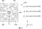
图6是表示第二实施方式中的读出线圈单元的结构的图。FIG. 6 is a diagram showing the configuration of a sense coil unit in a second embodiment.
图7是表示第二实施方式中的内窥镜插入形状检测装置的内部结构的方框图。Fig. 7 is a block diagram showing an internal configuration of an endoscope insertion shape detection device in a second embodiment.
图8是表示第二实施方式中的读出线圈单元成为与图7不同的状态的情况的图。FIG. 8 is a diagram showing a state in which the sense coil unit in the second embodiment is in a state different from that in FIG. 7 .
图9是表示第二实施方式中的读出线圈单元的第一变形例的结构的图。FIG. 9 is a diagram showing the configuration of a first modified example of the sense coil unit in the second embodiment.
图10是表示图9的读出线圈单元中的读出线圈组的配置的例子的图。FIG. 10 is a diagram showing an example of arrangement of a sense coil group in the sense coil unit of FIG. 9 .
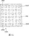
图11是表示第二实施方式中的读出线圈单元的第二变形例的结构的图。FIG. 11 is a diagram showing the configuration of a second modified example of the sense coil unit in the second embodiment.
图12是表示在图11的读出线圈单元上配置的拆装式读出线圈的结构的图。FIG. 12 is a diagram showing the configuration of a detachable sense coil disposed on the sense coil unit in FIG. 11 .
图13是表示在图11的读出线圈单元上配置的拆装式读出线圈的与图12不同的结构的图。FIG. 13 is a diagram illustrating a configuration of a detachable sense coil disposed on the sense coil unit in FIG. 11 that is different from that in FIG. 12 .
具体实施方式Detailed ways
下面参照附图说明本发明的实施方式。Embodiments of the present invention will be described below with reference to the drawings.
(第一实施方式)(first embodiment)
图1至图4是关于本发明的第一实施方式的图。图1是表示本发明的第一实施方式中的内窥镜系统的整体结构的图。图2是表示第一实施方式中的读出线圈单元的结构的图。图3是表示第一实施方式中的内窥镜插入形状检测装置的内部结构的方框图。图4是表示第一实施方式中的内窥镜插入形状检测装置进行的控制的内容的流程图。1 to 4 are diagrams related to a first embodiment of the present invention. FIG. 1 is a diagram showing the overall configuration of an endoscope system in a first embodiment of the present invention. FIG. 2 is a diagram showing the configuration of a sense coil unit in the first embodiment. Fig. 3 is a block diagram showing the internal configuration of the endoscope insertion shape detection device in the first embodiment. 4 is a flowchart showing the content of control performed by the endoscope insertion shape detection device in the first embodiment.
如图1所示,内窥镜系统1构成为具有下列主要部件:内窥镜3,其在作为被检体的患者2的体腔内对该体腔内的像进行拍摄,并将所拍摄到的该体腔内的像作为摄像信号而输出;视频处理器4,其对从内窥镜3输出的摄像信号进行图像处理等并输出;监视器5,其基于从视频处理器4输出的摄像信号,对内窥镜3所拍摄到的期望部位的像进行图像显示;插入形状检测用探针6;能载置患者2的床7;内窥镜插入形状检测装置8;监视器9;以及读出线圈单元23。As shown in FIG. 1 , an
并且,内窥镜3具有:插入到体腔内等的插入部11;与该插入部11的基端侧相连设置,用于把持着内窥镜3进行操作的操作部12;以及从操作部12的侧部延伸出,能与视频处理器4等外部装置连接的通用电缆13。In addition, the
在作为插入部11的前端的前端部14的内部设置有:用于对被摄体的像进行成像的物镜光学系统15;以及对由物镜光学系统15所成像的该被摄体的像进行拍摄并将所拍摄到的该被摄体的像作为摄像信号而输出的CCD(固体摄像元件)16。从CCD 16输出的摄像信号被输出给一端与CCD 16的后方连接的信号线17。信号线17设置成插通到插入部11、操作部12和通用电缆13的内部,另一端与视频处理器4电连接。由此,从CCD 16输出的摄像信号经由信号线17向视频处理器4输出。Inside the
在上述操作部12的侧部设置有用于插入插入形状检测用探针6的探针插入口18。探针插入口18与探针用通道19连通,该探针用通道19设计成插通于插入部11的内部,且该探针插入口18形成为能够将插入形状检测用探针6插通到探针用通道19的内部。A
插入形状检测用探针6具有能够插入到内窥镜3的探针插入口18和探针用通道19内的尺寸和形状等,多个源线圈21相隔规定的间隔而设置。The insertion
源线圈21是内窥镜插入形状检测装置8的一部分,同时构成为具有作为磁场产生部的功能的磁场产生元件,在插入形状检测用探针6被插入到内窥镜3中的状态下,源线圈21产生与插入部11的插入形状相应的磁场。The
并且,从插入形状检测用探针6的基端侧延伸出用于与内窥镜插入形状检测装置8连接的电缆22。内窥镜插入形状检测装置8通过电缆22来驱动源线圈21,从而使得产生磁场。Further, a
作为内窥镜插入形状检测装置8的一部分而设置在内窥镜插入形状检测装置8的外部的、作为磁场检测部的读出线圈单元23,例如配置在能够检测从设置于插入形状检测用探针6的多个源线圈21分别发出的磁场的如图1所示的位置上,该插入形状检测用探针6插入到插入于载置于床7上的患者2的体腔内的插入部11的探针用通道19中,并且该读出线圈单元23通过电缆24与内窥镜插入形状检测装置8连接。As a part of the endoscope insertion
而且,读出线圈单元23构成为包括9个作为磁场检测元件的读出线圈组23A、23B、23C、23D、23E、23F、23G、23H和23I。并且,如图2所示,所述的读出线圈组23A至23I在读出线圈单元23的内部配置成矩阵状。Further, the
如图2所示,读出线圈组23A构成为具有各源线圈21产生的、朝向X轴方向的读出线圈、朝向Y轴方向的读出线圈和朝向Z轴方向的读出线圈这三个读出线圈。此外,对于读出线圈组23A以外的其它读出线圈组,都具有与读出线圈组23A相同的结构。As shown in FIG. 2 , the sense coil group 23A is configured to have three sources: a sense coil facing the X-axis direction, a sense coil facing the Y-axis direction, and a sense coil facing the Z-axis direction generated by each
并且,由读出线圈组23A至23I检测出的磁场被输出到内窥镜插入形状检测装置8。再者,读出线圈单元23并不限于配置于上述位置,例如,也可以配置在床7的内部。而且,设置于读出线圈单元23的内部的读出线圈组并不限于图2所示9个读出线圈组被配置成矩阵状,例如也可以是9个之外的其它数量,也可以不配置成矩阵状。而且,设置于读出线圈单元23的内部的读出线圈组不限于由上述三个读出线圈构成,例如也可以构成为仅具有一个读出线圈。And, the magnetic fields detected by the readout coil groups 23A to 23I are output to the endoscope insertion
而且,如图3所示,内窥镜插入形状检测装置8构成为在内部具有:驱动各个源线圈21的源线圈驱动部31;经由源线圈驱动部13对各个源线圈21进行控制,以使各个源线圈21在规定的定时以及以规定的不同频率产生磁场的源线圈控制部32;信号检测部33;信号记录部34;源线圈位置解析部35;插入形状图像生成部36;信号控制部37;以及监视器驱动部39。Furthermore, as shown in FIG. 3 , the endoscope insertion
信号检测部33在基于从读出线圈单元23输出的磁场而将该磁场变换成磁场信号之后,基于信号控制部37的控制内容,将该磁场信号中,基于从相对于各源线圈21或规定的源线圈21处于规定的位置关系中的所述磁场检测元件输出的磁场的磁场信号,放大至可进行信号处理的电平并输出。进而,后面将叙述信号控制部37的控制内容。After the
作为控制部的信号控制部37向信号记录部34输出从信号检测部33输出的磁场信号。而且,信号控制部37在读出线圈单元23的X坐标、Y坐标和Z坐标中分别具有基于配置读出线圈组23A至23I的位置的阈值。由此,信号控制部37基于所述阈值以及从源线圈位置解析部35输出的、作为包含各源线圈21的位置信息的信号的位置信息信号,控制信号检测部33,以使信号检测部33能够接收基于从读出线圈组23A至23I中的、相对于各源线圈21处于规定的位置关系的读出线圈组输出的磁场的磁场信号。并且,信号控制部37并不限于硬件构成,例如,也可以在信号检测部33的内部构成为进行上述内容的控制的软件。而且,信号控制部37进行的控制也不限于上述的内容,例如也可以进行仅接收从信号检测部33输出的磁场信号中的、为了推定各源线圈21的位置所必要的、具有规定的信号电平的、规定数量的磁场信号的控制。具体来说,例如,信号控制部37进行的控制也可以是进行从信号检测部33仅接收如下磁场信号的控制:所述磁场信号基于从9个读出线圈组23A至23I中的具有比引起磁饱和的程度小的信号电平的、并且按照信号电平从大到小的顺序的4个读出线圈组输出的磁场。The
信号记录部34暂时记录从信号控制部37输出的磁场信号。The
作为磁场产生位置推定部的源线圈位置解析部35基于在信号记录部34中记录的磁场信号,推定各源线圈21的三维位置坐标,作为位置信息信号输出。The source coil
插入形状图像生成部36基于从源线圈位置解析部35输出的各源线圈21的位置信息信号而计算出插入部11的三维形状。而且,插入形状图像生成部36根据算出的插入部11的三维形状而生成插入部11的插入形状图形,作为插入形状图形信号而输出。The insertion shape
监视器驱动部39基于从插入形状图像生成部36输出的插入形状图形信号而驱动监视器9,在监视器9上描绘插入部11的插入形状图形。The
接下来参照图1至图4来说明使用本实施方式的内窥镜系统1的情况下的作用。Next, the operation when the
首先,手术者将插入形状检测用探针6从探针插入口18插入到内窥镜3中。之后,手术者将内窥镜3的通用电缆13与视频处理器4连接,将插入形状检测用探针6的电缆22以及从读出线圈单元23延伸出的电缆24与内窥镜插入形状检测装置8连接,将内窥镜3的插入部11插入到患者2的体腔内。于是,CCD 16对体腔内的像进行拍摄,将所拍摄的该体腔内的像作为摄像信号而输出。视频处理器4基于从CCD 16输出的摄像信号而进行图像处理等,并向监视器5输出进行了图像处理等之后的摄像信号。监视器5基于从视频处理器4输出的摄像信号,对内窥镜3所拍摄的体腔内的像进行图像显示。First, the operator inserts the insertion
而且,内窥镜插入形状检测装置8的源线圈控制部32经由源线圈驱动部31,对各个源线圈21进行控制,以使各源线圈21在不同的定时产生磁场。各个源线圈21基于源线圈控制部32的控制内容而产生与体腔内的插入部11的插入形状对应的磁场。Further, the source
各个源线圈21开始产生磁场后,读出线圈单元23首先通过如图2所示配置成矩阵状的读出线圈组23A至23I,检测从各个源线圈21产生的磁场。在读出线圈组23A至23I中检测出的磁场经由电缆24向内窥镜插入形状检测装置8输出。After each
信号检测部33基于从读出线圈单元23输出的磁场而将该磁场变换成磁场信号之后,将该磁场信号中,作为基于从读出线圈组23A、23C、23G和23I输出的磁场的磁场信号,即4组12个磁场信号放大为能进行信号处理的电平并输出。信号控制部37向信号记录部34输出从信号检测部33输出的4组12个磁场信号。信号记录部34暂时记录从信号控制部37输出的磁场信号。源线圈位置解析部35基于在信号记录部34中记录的4组12个磁场信号,推定关于多个源线圈21各自的三维位置坐标(图4的步骤S1),将该推定结果作为位置信息信号而输出到信号控制部37。After the
信号控制部37基于从源线圈位置解析部35输出的位置信息信号,当在多个源线圈21中,存在例如由于插入形状检测用探针6的整体没有插入到患者2的体腔内等,而导致源线圈位置解析部35连大致的位置都无法推定(图4的步骤S2)的源线圈的情况下,为了再次进行对该源线圈的位置的推定,信号控制部37再次通过信号检测部33接收基于从读出线圈组23A、23C、23G和23I输出的磁场的4组12个磁场信号(图4的步骤S6),并输出给信号记录部34。然后,源线圈位置解析部35根据记录在信号记录部34中的所述4组12个磁场信号,再次推定关于所述源线圈的三维位置坐标(图4的步骤S1),将该推定的结果作为位置信息信号而向信号控制部37输出。Based on the position information signal output from the source coil
信号控制部37根据从源线圈位置解析部35输出的位置信息信号,针对多个源线圈21中的通过源线圈位置解析部35能够推定出至少大致的位置(图4的步骤S2)的源线圈,对信号检测部33进行控制,以便能够接收基于来自相对于该源线圈处于规定的位置关系中,即处于能够精度良好地推定该源线圈的位置的位置关系中的读出线圈组的磁场的磁场信号。The
并且,接下来,将读出线圈单元23划分为对应于读出线圈组23A至23I的配置的如图2所示的假想区域。而且,信号控制部37具有将读出线圈单元23的全体划分成上述假想区域的值,作为上述X坐标和Y坐标的阈值。接下来以一个例子来说明下述情况:通过在源线圈位置解析部35中进行的所述推定,作为推定对象的规定的源线圈21被推定为位于区域X1与区域Y1交叉的区域(以下将这样的区域记为(X1,Y1)区域),并且位于Z轴方向的位置是坐标Z1的区域(以下将这样的区域记为(X1,Y1,Z1)区域)。And, next, the
当成为推定对象的上述规定的源线圈21在Z1<α(α为实数)的(X1,Y1,Z1)区域中时,即在(X1,Y1)区域中的离读出线圈组23A非常近的位置处时,由于磁饱和等原因,源线圈位置解析部35推定所述规定的源线圈21的位置时的精度有可能低下。为了防止如前所述的由于磁饱和等引起的位置推定时的精度低下,信号控制部37如下表1所示,对信号检测部33进行控制,以便能够接收基于从读出线圈组23C、23F、23H和23I输出的磁场的4组12个磁场信号(图4的步骤S3)。When the above-mentioned
并且,当成为推定对象的上述规定的源线圈21在α≤Z1≤β(β是满足α<β的实数)的(X1,Y1,Z1)区域中时,即在(X1,Y1)区域中且在Z轴上的坐标α与坐标β之间的位置处时,信号控制部37为了使检测的磁场的强度最佳化,如下表1所示,对信号检测部33进行控制,以便能够接收基于从读出线圈组23A、23B、23D和23E输出的磁场的4组12个磁场信号(图4的步骤S3)。And, when the above-mentioned
再者,当成为推定对象的上述规定的源线圈21在Z1>β的(X1,Y1,Z1)区域中时,即在(X1,Y1)区域中离读出线圈组23A非常远的位置处时,由于检测的磁场变得微弱等原因,源线圈位置解析部35推定上述规定的源线圈21的位置时的精度有可能低下。为了防止如前所述的由于检测的磁场微弱而引起的位置推定时的精度低下,信号控制部37如下表1所示,对信号检测部33进行控制,以便能够接收基于从读出线圈组23A、23C、23G和23I输出的磁场的4组12个磁场信号(图4的步骤S3)。In addition, when the above-mentioned
信号控制部37基于如下表1所示的由作为将读出线圈单元23的全体划分为该假想区域的值的X坐标的阈值和Y坐标的阈值、以及作为上述坐标α和坐标β的Z坐标的阈值构成的模板,设定用于接收由设置在插入形状检测用探针6上的多个源线圈21全体所产生的磁场信号的读出线圈组。The
[表1]
信号控制部37接收从与对信号检测部33进行的控制内容对应的读出线圈组输出的磁场的磁场信号(图4的步骤S4),向信号记录部34输出所接收的该磁场信号。The
信号记录部34暂时记录从信号控制部37输出的磁场信号。源线圈位置解析部35基于在信号记录部34中记录的磁场信号,推定关于多个源线圈21各自的三维位置坐标,将该推定结果作为位置信息信号向插入形状图像生成部36和信号控制部37输出。插入形状图像生成部36基于从源线圈位置解析部35输出的各源线圈21的三维位置坐标信息信号而计算出插入部11的三维形状,然后,插入形状图像生成部36根据算出的该三维形状生成插入部11的插入形状图形,并作为插入形状图形信号输出。监视器驱动部39基于从插入形状图像生成部36输出的插入形状图形信号而驱动监视器9,描绘出插入部11的插入形状图形。The
然后,源线圈位置解析部35为了对各个源线圈21再次进行位置推定,根据在信号记录部34中记录的磁场信号,即与信号控制部37对信号检测部33进行的控制内容对应的从读出线圈组输出的磁场的磁场信号,推定关于多个源线圈21各自的三维位置坐标(图4的步骤S5),将该推定结果作为位置信息信号向信号控制部37输出。Then, in order to estimate the position of each
此后,对于设置于插入形状检测用探针6上的多个源线圈21中的能够推定至少大致的位置的源线圈,基于表1所示的模板,由信号控制部37修改设定用于接收所输出的磁场的磁场信号的读出线圈组(图4的步骤S2、步骤S3、步骤S4和步骤S5)。并且,对于设置于插入形状检测用探针6上的多个源线圈21中的连大致的位置都不能够推定的源线圈,根据基于从读出线圈组23A、23C、23G和23I输出的磁场的4组12个磁场信号,由源线圈位置解析部35再次推定关于上述源线圈的三维位置坐标(图4的步骤S2、步骤S6和步骤S1)。Thereafter, among the plurality of source coils 21 provided on the insertion
本实施方式的内窥镜插入形状检测装置8中的信号控制部37基于从源线圈位置解析部35输出的位置信息信号,对信号检测部33进行控制,从而选择在检测由设置在检测用探针6上的多个源线圈21各自产生的磁场时使用的读出线圈组23A至23I的配置。根据该作用,信号控制部37对于多个源线圈21,能够接收从处于能够精度良好地推定该源线圈21各自的位置的位置关系中的读出线圈组输出的磁场的磁场信号。由此,本实施方式的内窥镜插入形状检测装置8能够比以往更正确地描绘出插入部11的插入形状,其结果,手术者能够更加顺畅地进行内窥镜3的插入操作。The
(第2实施方式)(second embodiment)
图5至图13涉及本发明的第二实施方式。并且省略了对具有与第一实施方式相同的结构的部分的详细说明。此外,对于与第一实施方式相同的构成要素使用相同的标号,并省略说明。5 to 13 relate to a second embodiment of the present invention. And a detailed description of parts having the same configuration as that of the first embodiment is omitted. In addition, the same code|symbol is used for the same component as 1st Embodiment, and description is abbreviate|omitted.
图5是表示第二实施方式中的内窥镜系统的整体结构的图。图6是表示第二实施方式中的读出线圈单元的结构的图。图7是表示第二实施方式中的内窥镜插入形状检测装置的内部结构的方框图。图8是表示第二实施方式中的读出线圈单元形成为与图7不同的状态的情况的图。图9是表示第二实施方式中的读出线圈单元的第一变形例的结构的图。图10是表示图9的读出线圈单元中的读出线圈组的配置的例子的图。图11是表示第二实施方式中的读出线圈单元的第二变形例的结构的图。图12是表示在图11的读出线圈单元上配置的拆装式读出线圈的结构的图。图13是表示在图11的读出线圈单元上配置的拆装式读出线圈中与图12不同的结构的图。FIG. 5 is a diagram showing an overall configuration of an endoscope system in a second embodiment. FIG. 6 is a diagram showing the configuration of a sense coil unit in a second embodiment. Fig. 7 is a block diagram showing an internal configuration of an endoscope insertion shape detection device in a second embodiment. FIG. 8 is a diagram showing a state in which the sense coil unit in the second embodiment is formed in a state different from that in FIG. 7 . FIG. 9 is a diagram showing the configuration of a first modified example of the sense coil unit in the second embodiment. FIG. 10 is a diagram showing an example of arrangement of a sense coil group in the sense coil unit of FIG. 9 . FIG. 11 is a diagram showing the configuration of a second modified example of the sense coil unit in the second embodiment. FIG. 12 is a diagram showing the configuration of a detachable sense coil disposed on the sense coil unit in FIG. 11 . FIG. 13 is a diagram showing a structure different from that of FIG. 12 among the detachable sense coils disposed on the sense coil unit of FIG. 11 .
如图5所示,内窥镜系统1a构成为具有下列主要部件:内窥镜3,其在作为被检体的患者2的体腔内对体腔内的像进行拍摄,并将所拍摄到的该体腔内的像作为摄像信号而输出;视频处理器4,其对从内窥镜3输出的摄像信号进行图像处理等并输出;监视器5,其基于从视频处理器4输出的摄像信号,对内窥镜3所拍摄到的期望部位的像进行图像显示;插入形状检测用探针6;能载置患者2的床7;内窥镜插入形状检测装置8a;监视器9;以及读出线圈单元23a。并且,在插入形状检测用探针6上,相隔规定的间隔设置有作为内窥镜插入形状检测装置8a的一部分、且构成为具有作为磁场产生部的功能的多个磁场产生元件的多个源线圈21。As shown in FIG. 5 , the endoscope system 1a is configured to have the following main components: an
作为内窥镜插入形状检测装置8a的一部分而设置在内窥镜插入形状检测装置8a的外部的、作为磁场检测部的读出线圈单元23a,例如配置在能够检测从设置于插入形状检测用探针6的多个源线圈21分别发出的磁场的如图5所示的位置上,该插入形状检测用探针6插入到插入于载置于床7上的患者2的体腔内的插入部11的探针用通道19中,并且该读出线圈单元23通过电缆24与内窥镜插入形状检测装置8a连接。并且,读出线圈单元23a构成为具有作为磁场检测元件的4个读出线圈组23J、23K、23L和23M、臂驱动部23N和臂101。As a part of the endoscope insertion
如图6所示,读出线圈组23J构成为具有源线圈21所产生的、朝向X轴方向的读出线圈、朝向Y轴方向的读出线圈和朝向Z轴方向的读出线圈这三个读出线圈。此外,对于读出线圈组23J以外的其它读出线圈组,都具有与读出线圈组23J相同的结构。由读出线圈组23J至23M检测出的磁场作为磁场信号被输出到内窥镜插入形状检测装置8a。如图6所示,读出线圈组23J至23M分别具有上述三个源线圈被配置成大致L字形的部件的结构,并且,该大致L字形的部件的每一个部件都经由臂101与臂驱动部23N连接。As shown in FIG. 6 , the
臂驱动部23N通过信号线,经由电缆24与内窥镜插入形状检测装置8a连接。并且,臂驱动部23N通过基于内窥镜插入形状检测装置8a的控制内容来驱动臂101,从而能够在臂101的可动范围MR内变更读出线圈组23J至23M的位置。The
如图7所示,内窥镜插入形状检测装置8a在内部具有:驱动各个源线圈21的源线圈驱动部31;通过源线圈驱动部31,对源线圈21的磁场产生定时和频率等进行控制的源线圈控制部32;信号检测部33;信号记录部34;源线圈位置解析部35;插入形状图像生成部36;臂控制部38;监视器驱动部39。As shown in FIG. 7 , the endoscope insertion
作为控制部的臂控制部38根据从信号检测部33输出的磁场信号、和从源线圈位置解析部35输出的作为含有源线圈21的位置信息的信号的位置信息信号,控制臂驱动部23N而使臂101伸缩,从而把读出线圈组23J至23M的位置变更为与源线圈21成规定的位置关系。并且,臂控制部38进行的控制并不限于前述内容,例如也可以在通过信号检测部33接收了基于从读出线圈组23J至23M输出的磁场的4组12个磁场信号之后,基于该4组12个磁场信号的信号电平的平均值,控制臂驱动部23N而使臂101伸缩。The
下面参照图5至图8说明使用本实施方式涉及的内窥镜系统1a时的作用。Next, the operation when the endoscope system 1a according to this embodiment is used will be described with reference to FIGS. 5 to 8 .
首先,手术者将插入形状检测用探针6从探针插入口18插入到内窥镜3中。之后,手术者将内窥镜3的通用电缆13与视频处理器4连接,将插入形状检测用探针6的电缆22以及从读出线圈单元23a延伸出的电缆24与内窥镜插入形状检测装置8a连接,将内窥镜3的插入部11插入到患者2的体腔内。于是,CCD 16对体腔内的像进行拍摄,将所拍摄的该体腔内的像作为摄像信号而输出。视频处理器4基于从CCD 16输出的摄像信号而进行图像处理等,并向监视器5输出进行了图像处理等之后的摄像信号。监视器5基于从视频处理器4输出的摄像信号,对内窥镜3所拍摄的体腔内的像进行图像显示。First, the operator inserts the insertion
而且,内窥镜插入形状检测装置8a的源线圈控制部32经由源线圈驱动部31,对各个源线圈21进行控制,以使各源线圈21在不同的定时产生磁场。各个源线圈21基于源线圈控制部32的控制内容而产生与体腔内的插入部11的插入形状对应的磁场。Further, the source
在各个源线圈21开始产生磁场后,读出线圈单元23a首先在初始状态、即臂101的伸缩状态为处于如图6所示的位置的状态下,通过读出线圈组23J至23M检测由各个源线圈21产生的磁场。在读出线圈组23J至23M中检测出的磁场经由电缆24向内窥镜插入形状检测装置8a输出。After each
信号检测部33基于从读出线圈单元23a输出的磁场而将该磁场变换成磁场信号之后,将该磁场信号放大成能进行信号处理的电平并输出。信号记录部34暂时记录从信号检测部33输出的磁场信号。源线圈位置解析部35基于在信号记录部34中记录的磁场信号,推定关于多个源线圈21各自的三维位置坐标,将该推定结果作为位置信息信号而输出到臂控制部38。The
并且,源线圈位置解析部35基于在信号记录部34中记录的磁场信号,推定关于多个源线圈21各自的三维位置坐标,将该推定的结果作为位置信息信号向插入形状图像生成部36输出。插入形状图像生成部36基于从源线圈位置解析部35输出的各个源线圈21的三维位置坐标信息信号而算出插入部11的三维形状之后,根据所算出的该三维形状生成插入部11的插入形状图形,并作为插入形状图形信号输出。监视器驱动部39基于从插入形状图像生成部36输出的插入形状图形信号而驱动监视器9,描绘出插入部11的插入形状图形。Then, the source coil
臂控制部38基于从信号检测部33输出的磁场信号和从源线圈位置解析部35输出的位置信息信号,控制臂驱动部23N而使臂101伸缩,从而变更读出线圈组23J至23M的位置,以使读出线圈组23J至23M配置在相对于规定的源线圈21成为规定的位置关系的位置处。并且,上述成为规定的位置关系的位置是如下的位置:读出线圈组23J至23M能够以规定的强度接收从设置于插入形状检测用探针6上的源线圈21中的、发出成为所有源线圈的大致平均值的强度的磁场的规定源线圈21所产生的磁场的位置。并且,上述规定的强度是不会使源线圈位置解析部35推定各个源线圈21的位置时的精度低下的程度的强度,例如是不会在读出线圈组23J至23M中的任一方中发生磁饱和且不会使检测的磁场变得微弱的程度的强度。The
当产生成为所有源线圈的大致平均值的强度的磁场的规定源线圈21位于离读出线圈单元23a非常近的位置处时,臂控制部38为了防止由于磁饱和而导致的源线圈位置解析部35推定所述规定的源线圈21的位置时的精度低下,例如控制臂驱动部23N来使臂101伸展,以使读出线圈组23J至23M的位置成为图8所示的状态。When the
并且,当产生成为所有源线圈的大致平均值的强度的磁场的规定源线圈21位于离读出线圈单元23a远的位置处时,臂控制部38为了防止由于检测的磁场变得微弱而导致的源线圈位置解析部35推定所述规定源线圈21的位置时的精度低下,例如控制臂驱动部23N来使臂101伸展,以使读出线圈组23J至23M的位置成为图8所示的状态。Furthermore, when the
而且,当从产生成为所有源线圈的大致平均值的强度的磁场的规定源线圈21的位置到读出线圈单元23a的位置的距离是能够以上述规定的强度来检测磁场的适当距离时,臂控制部38控制臂驱动部23N而缩回臂101,以使例如读出线圈组23J至23M的位置成为与如图6所示的读出线圈单元23a的初始状态大致相同的状态。Furthermore, when the distance from the position of the
并且,关于臂控制部38进行的上述的内容的控制,如果能够以不会使源线圈位置解析部35推定各源线圈21的位置时的精度变得低下的程度的强度来检测由设置在插入形状检测用探针6上的各源线圈21发出的磁场,则臂控制部38进行的上述的内容的控制并不限于对分别由3个读出线圈构成的读出线圈组23J至23M进行。例如,臂控制部38也可以对具有将读出线圈一个一个分别连接到臂101的结构的读出线圈单元23a进行上述内容的控制。In addition, if the above-mentioned control performed by the
并且,本实施方式的内窥镜系统1a也可以取代读出线圈单元23a,而使用具有图9和图10所示的结构的读出线圈单元23b来构成。In addition, the endoscope system 1a of this embodiment may be configured using a
作为内窥镜插入形状检测装置8a的一部分、设置在内窥镜插入形状检测装置8a的外部的作为磁场检测部的读出线圈单元23b具有臂驱动部23N、读出线圈部102和臂103。
在读出线圈部102中,设置有读出线圈组23J至23M,并且它们分别配置在图10所示的位置上。In the
臂103具有可向前后、左右以及上下移动的结构,通过设置在基端侧的臂驱动部23N的控制,能够变更设置在前端侧的读出线圈部102的位置。The
由于作为本实施方式的第一变形例的读出线圈单元23b具备上述的结构,所以臂控制部38通过控制臂驱动部23N而使臂103伸缩等,以使得读出线圈组23J至23M配置在成为规定的位置关系的、能够以规定的强度接收由产生成为全部源线圈的大致平均值的强度的磁场的规定源线圈21所产生的磁场的位置处,从而能够变更读出线圈组23J至23M的位置。并且,上述规定的强度是不会使源线圈位置解析部35推定各源线圈21的位置时的精度变得低下的程度的强度,例如是不会在读出线圈组23J至23M中的任一方中引起磁饱和且不会使检测的磁场变得微弱的程度的强度。Since the
而且,作为本实施方式的第2变形例,读出线圈单元23b的读出线圈部102也可以具有如图11和图12所示的读出线圈部102A的结构。Furthermore, as a second modified example of the present embodiment, the
读出线圈部102A例如具有设有多个像图11所示的连接器23S1那样的连接器的连接器组23S。并且,读出线圈部102A具有在连接器组23S中,能够与具有如图12所示的结构的拆装式读出线圈23X自由拆装的结构。The
设置于连接器组23S中的连接器23S1等多个连接器分别经由未图示的信号线与内窥镜插入形状检测装置8a连接。A plurality of connectors such as the connector 23S1 provided in the
作为磁场检测元件的拆装式读出线圈23X构成为具有:由朝向X轴方向的读出线圈、朝向Y轴方向的读出线圈和朝向Z轴方向的读出线圈这三个读出线圈构成的读出线圈组23Q;以及设置于连接器组23S中的、对于连接器23S1等连接器可自由拆装的连接器23R。The
并且,若拆装式读出线圈23X能接收由设置在连接器组23S中的源线圈21产生的磁场,并具有对于连接器23S1等连接器可自由拆装的结构,则并不限于图12所示的装置,例如也可以构成为图13所示的拆装式读出线圈23Y那样的装置。拆装式读出线圈23Y在读出线圈组23Q的周围设置有连接部23T,并且,连接部23T对于设置于读出线圈部102A上的连接部23Sa是可自由拆装的。In addition, if the
并且,读出线圈组23Q并不限于由上述的三个读出线圈构成的结构,例如也可以是仅由朝向X轴方向的读出线圈、朝向Y轴方向的读出线圈或朝向Z轴方向的读出线圈中的任一方构成的结构。In addition, the sense coil group 23Q is not limited to the structure composed of the above-mentioned three sense coils, for example, only the sense coils facing the X-axis direction, the sense coils facing the Y-axis direction, or the sense coils facing the Z-axis direction may be used. The structure composed of either side of the readout coil.
下面说明读出线圈单元23b具有读出线圈部102A时的作用。Next, the operation when the
手术者在使用内窥镜插入形状检测装置8a前,首先将拆装式读出线圈23X与连接器组23S的任一个连接器连接。并且,由于可以在连接器组23S中同时连接多个拆装式读出线圈23X,所以在下面的说明中,对在设置在如图11所示的连接器组23S的4个角落上的连接器23S1、连接器23S2、连接器23S3和连接器23S4上各连接一个拆装式读出线圈23X的结构进行说明。The operator first connects the
此后,当手术者起动了内窥镜系统1a的各个部分时,各个源线圈21基于源线圈控制部32的控制内容而产生与体腔内的插入部11的插入形状对应的磁场。Thereafter, when the operator activates each part of the endoscope system 1 a , each
在各源线圈21开始产生磁场后,读出线圈单元23b首先通过设置在连接器组23S的4个角落上的拆装式读出线圈23X,检测从各源线圈21产生的磁场。将分别安装在连接器组23S的4个角落上的4个拆装式读出线圈23X所检测出的磁场经由电缆24向内窥镜插入形状检测装置8a输出。After each
信号检测部33基于从读出线圈单元23b输出的磁场而将该磁场转换成磁场信号之后,将该磁场信号放大成能进行信号处理的电平并输出。信号记录部34暂时记录从信号检测部33输出的磁场信号。源线圈位置解析部35基于在信号记录部34中记录的磁场信号,推定在连接器组23S中连接拆装式读出线圈23X的位置和个数、以及关于多个源线圈21各自的三维位置坐标,将该推定结果作为位置信息信号向臂控制部38输出。The
臂控制部38基于从信号检测部33输出的磁场信号和从源线圈位置解析部35输出的位置信息信号,控制臂驱动部23N而使臂103伸缩,以使得分别安装在连接器组23S的4个角落上的4个拆装式读出线圈23X被配置在相对于规定的源线圈21成为规定的位置关系的位置处,从而变更读出线圈单元23b的位置。并且,成为上述规定的位置关系的位置是如下的位置,即4个拆装式读出线圈23X能以规定的强度接收从设置于插入形状检测用探针6上的源线圈21中的、产生成为全部源线圈的大致平均值的强度的磁场的规定源线圈21所产生的磁场的位置。并且,上述规定的强度是不会使源线圈位置解析部35推定各源线圈21的位置时的精度变得低下的程度的强度,例如是不会在分别安装在连接器组23S的4个角落上的4个拆装式读出线圈23X中的任一方中引起磁饱和且不会使检测的磁场变得微弱的程度的强度。Based on the magnetic field signal output from the
并且,即使通过臂控制部38的控制,变更了读出线圈单元23b的位置之后,例如在设置在连接器组23S的4个角落上的拆装式读出线圈23X中的任一方中,由于由产生成为所有源线圈的大致平均值的强度的磁场的规定源线圈21所产生的磁场,而产生磁饱和,由此会发生源线圈位置解析部35推定各源线圈21的位置时的精度变得低下的情况。在这种情况下,插入形状图像生成部36根据从源线圈位置解析部35输出的位置信息信号,向监视器驱动部39输出将具有促使拆装式读出线圈23X的连接位置的变更或连接数的减少等内容的字符串叠加显示在内窥镜3的插入部11的插入形状图形上的插入形状图形信号。In addition, even after the position of the read
监视器驱动部39根据从插入形状图像生成部36输出的插入形状图形信号而驱动监视器9,将具有促使手术者变更拆装式读出线圈23X的连接位置、减少连接数量等的内容的字符串叠加描绘在插入部11的插入形状图形上。The
之后,手术者参照上述字符串而进行拆装式读出线圈23X的连接位置的变更或连接数量的减少等,当拆装式读出线圈23X中的任一方中都变成不会发生磁饱和的状态时,插入形状图像生成部36基于从源线圈位置解析部35输出的位置信息信号而中止上述字符串的显示,将进行了拆装式读出线圈23X的连接位置的变更或连接数量的减少等之后的插入部11的插入形状图形作为插入形状图形信号向监视器驱动部39输出。Thereafter, the operator changes the connection position of the
并且,即使通过臂控制部38的控制,变更了读出线圈单元23b的位置之后,由于例如由设置在连接器组23S的4个角落上的拆装式读出线圈23X进行检测的、由产生成为所有源线圈的大致平均值的强度的磁场的规定源线圈21所产生的磁场变得微弱,从而发生源线圈位置解析部35推定各源线圈21的位置时的精度变得低下的情况。在这种情况下,插入形状图像生成部36根据从源线圈位置解析部35输出的位置信息信号,向监视器驱动部39输出将具有促使拆装式读出线圈23X的连接位置的变更或连接数量的增加等内容的字符串重叠显示在内窥镜3的插入部11的插入形状图形上的插入形状图形信号。And, even if the position of the
监视器驱动部39根据从插入形状图像生成部36输出的插入形状图形信号而驱动监视器9,将促使手术者变更拆装式读出线圈23X的连接位置、或增加连接数量等的内容的字符串重叠描绘在插入部11的插入形状图形上。The
之后,当手术者参照上述字符串进行了拆装式读出线圈23X的连接位置的变更或连接数量的增加等时,拆装式读出线圈23X中的任一方中都变成所检测的磁场不是微弱的磁场的状态。在上述状态下,插入形状图像生成部36基于从源线圈位置解析部35输出的位置信息信号而中止上述字符串的显示,将进行了拆装式读出线圈23X的连接位置的变更或连接数量的增加等之后的插入部11的插入形状图形作为插入形状图形信号,而向监视器驱动部39输出。Afterwards, when the operator changes the connection position of the
本实施方式的内窥镜插入形状检测装置8a具有如下结构,即臂控制部38对读出线圈单元23a或读出线圈单元23b进行控制,以使得读出线圈组23J至23M或拆装式读出线圈23X能够以不会引起磁饱和、且不会使检测的磁场变得微弱的程度的强度的规定强度,来接收由产生成为所有源线圈的大致平均值的强度的磁场的规定源线圈21所产生的磁场。即,臂控制部38基于从源线圈位置解析部35输出的位置信息信号,对读出线圈单元23a或读出线圈单元23b进行控制,从而选择在检测由产生成为所有源线圈的大致平均值的强度的磁场的规定源线圈21所产生的磁场时所使用的读出线圈组23J至23M或拆装式读出线圈23X的配置。由此,本实施方式的内窥镜插入形状检测装置8a能够精度良好地推定源线圈21各自的位置,且能够比以往技术更正确地描绘出插入部11的插入形状。其结果,手术者能够更加顺畅地进行内窥镜3的插入操作。The endoscope insertion
Claims (7)
Applications Claiming Priority (3)
| Application Number | Priority Date | Filing Date | Title |
|---|---|---|---|
| JP2004348945AJP4749703B2 (en) | 2004-12-01 | 2004-12-01 | Endoscope insertion shape detection device |
| JP348945/2004 | 2004-12-01 | ||
| PCT/JP2005/021988WO2006059644A1 (en) | 2004-12-01 | 2005-11-30 | Endoscope insertion shape detecting device |
Publications (2)
| Publication Number | Publication Date |
|---|---|
| CN101056573Atrue CN101056573A (en) | 2007-10-17 |
| CN101056573B CN101056573B (en) | 2010-11-03 |
Family
ID=36565077
Family Applications (1)
| Application Number | Title | Priority Date | Filing Date |
|---|---|---|---|
| CN2005800388853AExpired - Fee RelatedCN101056573B (en) | 2004-12-01 | 2005-11-30 | Endoscope insertion shape detection device |
Country Status (5)
| Country | Link |
|---|---|
| US (1) | US8192354B2 (en) |
| EP (1) | EP1818004B1 (en) |
| JP (1) | JP4749703B2 (en) |
| CN (1) | CN101056573B (en) |
| WO (1) | WO2006059644A1 (en) |
Cited By (4)
| Publication number | Priority date | Publication date | Assignee | Title |
|---|---|---|---|---|
| CN102939040A (en)* | 2010-06-09 | 2013-02-20 | 奥林巴斯医疗株式会社 | Probe shape detection device and probe shape detection method |
| CN104142119A (en)* | 2014-08-20 | 2014-11-12 | 广州市易轩生物科技有限公司 | Sensing device for three-dimensional shape of hose |
| CN105358037A (en)* | 2013-08-22 | 2016-02-24 | 奥林巴斯株式会社 | Location detection device and location detection system |
| CN110731746A (en)* | 2019-09-10 | 2020-01-31 | 中山大学附属第一医院 | A device for estimating the shape of an endoscope |
Families Citing this family (6)
| Publication number | Priority date | Publication date | Assignee | Title |
|---|---|---|---|---|
| JP4914574B2 (en)* | 2005-04-18 | 2012-04-11 | オリンパスメディカルシステムズ株式会社 | Endoscope shape detection device |
| EP2062523A4 (en)* | 2006-09-14 | 2015-08-12 | Olympus Medical Systems Corp | MEDICAL GUIDING SYSTEM AND METHOD FOR CONTROLLING THE MEDICAL DEVICE |
| JP5918548B2 (en) | 2012-01-24 | 2016-05-18 | 富士フイルム株式会社 | Endoscopic image diagnosis support apparatus, operation method thereof, and endoscopic image diagnosis support program |
| JP5687788B1 (en)* | 2014-03-27 | 2015-03-18 | 株式会社マコメ研究所 | Catheter detection device |
| US10383543B2 (en)* | 2015-11-11 | 2019-08-20 | Biosense Webster (Israel) Ltd. | Symmetric short contact force sensor with four coils |
| DE102017008148A1 (en)* | 2017-08-29 | 2019-02-28 | Joimax Gmbh | Sensor unit, intraoperative navigation system and method for detecting a surgical instrument |
Family Cites Families (13)
| Publication number | Priority date | Publication date | Assignee | Title |
|---|---|---|---|---|
| US5681260A (en)* | 1989-09-22 | 1997-10-28 | Olympus Optical Co., Ltd. | Guiding apparatus for guiding an insertable body within an inspected object |
| US5253647A (en)* | 1990-04-13 | 1993-10-19 | Olympus Optical Co., Ltd. | Insertion position and orientation state pickup for endoscope |
| US6059718A (en)* | 1993-10-18 | 2000-05-09 | Olympus Optical Co., Ltd. | Endoscope form detecting apparatus in which coil is fixedly mounted by insulating member so that form is not deformed within endoscope |
| US5729129A (en)* | 1995-06-07 | 1998-03-17 | Biosense, Inc. | Magnetic location system with feedback adjustment of magnetic field generator |
| US5997473A (en)* | 1996-09-06 | 1999-12-07 | Olympus Optical Co., Ltd. | Method of locating a coil which consists of determining the space occupied by a source coil generating a magnetic field |
| JP3571675B2 (en)* | 1998-03-18 | 2004-09-29 | オリンパス株式会社 | Coil position measuring device and coil position measuring method |
| JP3236565B2 (en) | 1998-03-18 | 2001-12-10 | オリンパス光学工業株式会社 | Position estimation device |
| US6511417B1 (en)* | 1998-09-03 | 2003-01-28 | Olympus Optical Co., Ltd. | System for detecting the shape of an endoscope using source coils and sense coils |
| JP3746617B2 (en) | 1998-09-04 | 2006-02-15 | オリンパス株式会社 | Position estimation device |
| US6773393B1 (en)* | 1999-08-05 | 2004-08-10 | Olympus Optical Co., Ltd. | Apparatus and method for detecting and displaying form of insertion part of endoscope |
| US6745065B2 (en)* | 2001-08-02 | 2004-06-01 | Olympus Corporation | Endoscope apparatus |
| US20040204645A1 (en)* | 2003-04-10 | 2004-10-14 | Vahid Saadat | Scope position and orientation feedback device |
| EP1797812B1 (en)* | 2003-08-22 | 2011-04-13 | Olympus Corporation | Device for detecting shape of endoscope |
- 2004
- 2004-12-01JPJP2004348945Apatent/JP4749703B2/ennot_activeExpired - Fee Related
- 2005
- 2005-11-30EPEP05811281.4Apatent/EP1818004B1/ennot_activeNot-in-force
- 2005-11-30CNCN2005800388853Apatent/CN101056573B/ennot_activeExpired - Fee Related
- 2005-11-30WOPCT/JP2005/021988patent/WO2006059644A1/enactiveApplication Filing
- 2007
- 2007-05-29USUS11/807,496patent/US8192354B2/enactiveActive
Cited By (7)
| Publication number | Priority date | Publication date | Assignee | Title |
|---|---|---|---|---|
| CN102939040A (en)* | 2010-06-09 | 2013-02-20 | 奥林巴斯医疗株式会社 | Probe shape detection device and probe shape detection method |
| CN102939040B (en)* | 2010-06-09 | 2015-02-25 | 奥林巴斯医疗株式会社 | Probe shape detection device and probe shape detection method |
| CN105358037A (en)* | 2013-08-22 | 2016-02-24 | 奥林巴斯株式会社 | Location detection device and location detection system |
| CN105358037B (en)* | 2013-08-22 | 2017-07-25 | 奥林巴斯株式会社 | Position detecting device and position detecting system |
| CN104142119A (en)* | 2014-08-20 | 2014-11-12 | 广州市易轩生物科技有限公司 | Sensing device for three-dimensional shape of hose |
| CN104142119B (en)* | 2014-08-20 | 2017-06-09 | 广州市易轩生物科技有限公司 | Flexible pipe 3D shape sensing device |
| CN110731746A (en)* | 2019-09-10 | 2020-01-31 | 中山大学附属第一医院 | A device for estimating the shape of an endoscope |
Also Published As
| Publication number | Publication date |
|---|---|
| EP1818004B1 (en) | 2015-10-07 |
| CN101056573B (en) | 2010-11-03 |
| EP1818004A1 (en) | 2007-08-15 |
| WO2006059644A1 (en) | 2006-06-08 |
| EP1818004A4 (en) | 2009-01-21 |
| US20070232854A1 (en) | 2007-10-04 |
| US8192354B2 (en) | 2012-06-05 |
| JP4749703B2 (en) | 2011-08-17 |
| JP2006149972A (en) | 2006-06-15 |
Similar Documents
| Publication | Publication Date | Title |
|---|---|---|
| US20080303898A1 (en) | Endoscopic image processing apparatus | |
| US20200320702A1 (en) | Medical image processing device, endoscope system, medical image processing method, and program | |
| US8192354B2 (en) | Endoscope inserted-shape detecting apparatus | |
| CN1494873A (en) | Ultrasonic diagnostic device, ultrasonic probe, and ultrasonic image photography support method | |
| CN1612708A (en) | Endoscope | |
| CN101040767A (en) | Endoscope and display device | |
| CN113365545B (en) | Image recording device, image recording method, and image recording program | |
| JP7385731B2 (en) | Endoscope system, image processing device operating method, and endoscope | |
| CN111031889B (en) | Medical image processing apparatus and medical image processing method | |
| JPWO2008136098A1 (en) | Medical image processing apparatus and medical image processing method | |
| JP4855901B2 (en) | Endoscope insertion shape analysis system | |
| CN104994792A (en) | Ultrasonic diagnostic device and medical image processing device | |
| US20220414880A1 (en) | Medical system, information processing method, and computer-readable medium | |
| US20180161063A1 (en) | Ultrasound observation apparatus, method of operating ultrasound observation apparatus, and computer readable recording medium | |
| CN116940274A (en) | Shape measurement system for endoscope and shape measurement method for endoscope | |
| JP4855902B2 (en) | Biological observation system | |
| US20230289926A1 (en) | Processing device, processing program, processing method, and processing system | |
| US20240307127A1 (en) | Processing apparatus and information processing method | |
| US20250255460A1 (en) | Medical support device, endoscope, medical support method, and program | |
| US20250292401A1 (en) | Image processing device, endoscope system, image processing method, and program | |
| JP2020141834A (en) | Endoscope processor and endoscope system | |
| JP6585352B2 (en) | Ultrasonic observation apparatus, ultrasonic endoscope, ultrasonic diagnostic system, operation method of ultrasonic observation apparatus, and operation program of ultrasonic observation apparatus | |
| US20250009329A1 (en) | Image processing apparatus, medical diagnostic apparatus, ultrasonic endoscope apparatus, image processing method, and program | |
| US20220409010A1 (en) | Medical image processing device, operation method therefor, and endoscope system | |
| JP4823539B2 (en) | Endoscope insertion shape detection device |
Legal Events
| Date | Code | Title | Description |
|---|---|---|---|
| C06 | Publication | ||
| PB01 | Publication | ||
| C10 | Entry into substantive examination | ||
| SE01 | Entry into force of request for substantive examination | ||
| C14 | Grant of patent or utility model | ||
| GR01 | Patent grant | ||
| CF01 | Termination of patent right due to non-payment of annual fee | Granted publication date:20101103 | |
| CF01 | Termination of patent right due to non-payment of annual fee |