CN101048102A - Link systems and articulation mechanisms for remote manipulation of surgical or diagnostic tools - Google Patents
Link systems and articulation mechanisms for remote manipulation of surgical or diagnostic toolsDownload PDFInfo
- Publication number
- CN101048102A CN101048102ACNA2005800251545ACN200580025154ACN101048102ACN 101048102 ACN101048102 ACN 101048102ACN A2005800251545 ACNA2005800251545 ACN A2005800251545ACN 200580025154 ACN200580025154 ACN 200580025154ACN 101048102 ACN101048102 ACN 101048102A
- Authority
- CN
- China
- Prior art keywords
- links
- link
- movement
- cables
- cable
- Prior art date
- Legal status (The legal status is an assumption and is not a legal conclusion. Google has not performed a legal analysis and makes no representation as to the accuracy of the status listed.)
- Granted
Links
Images


Landscapes
- Surgical Instruments (AREA)
- Endoscopes (AREA)
Abstract
Description
Translated fromChinese相关申请的交叉引用Cross References to Related Applications
本申请要求于2004年6月7日提交的美国临时申请No.60/577,757的权益,此处该临时申请的内容结合在本公开内容中作为参考。This application claims the benefit of US Provisional Application No. 60/577,757, filed June 7, 2004, the contents of which are hereby incorporated by reference into this disclosure.
技术领域technical field
本发明涉及链节(link)系统及其应用,包括手术或诊断器械和工具的远程引导和操纵。The present invention relates to link systems and applications thereof, including remote guidance and manipulation of surgical or diagnostic instruments and tools.
背景技术Background technique
能够容易地远程操纵、引导和/或操作器械和工具的能力在许多工业和应用中是有意义的,尤其是在希望将器械或工具导引到不易于用手导引或者会存在风险或危险的工作空间内的情况下。这些可包括应用工具或器械难以到达目标位置的情况,例如手动到达目标位置受限的某些外科手术过程,或机器的制造或修理,乃至商业和家庭使用。其它情况例如可包括工作环境对于使用者而言是危险的工业应用,例如工作空间暴露在危险的化学物质下。其它情况还可例如包括使用者会有危险的法律执行或军事应用,例如将工具或器械部署在危险或敌对位置。The ability to easily steer, guide, and/or operate instruments and tools remotely is of interest in many industries and applications, especially where it is desired to direct the instruments or tools to places where manual guidance is not easy or would present a risk or hazard in the working space. These can include situations where the application tool or instrument is difficult to reach the target site, such as certain surgical procedures where manual access to the target site is limited, or the manufacture or repair of machinery, or even commercial and home use. Other situations may include, for example, industrial applications where the working environment is hazardous for the user, such as where the working space is exposed to hazardous chemicals. Other situations may also include, for example, law enforcement or military applications where the user would be at risk, such as deploying a tool or implement in a dangerous or hostile location.
以外科手术过程作为说明性示例,过程例如内窥镜检查和腹腔镜检查通常使用从身体外部的位置在目标器官或组织内操纵或朝该目标器官或组织操纵的器械。内窥镜检查过程的示例包括乙状结肠镜检查、结肠镜检查、食管胃十二指肠镜检查和支气管镜检查。传统上,内窥镜的插入管可通过向前推动而前进,通过向后拉动而收回。可通过扭曲以及一般的向上/向下和向左/向右运动来指引管的端部。该受限的运动范围往往使得难以通过锐角处(例如在直肠乙状结肠内),会使病人不舒服并增加周围组织受到损伤的危险。腹腔镜检查包括根据解剖标志安置套针工作口(port)。工作口的数量通常根据预期过程以及要获得令人满意的组织松动(mobilization)以及手术区暴露所需的器械的数量而改变。尽管腹腔镜手术存在许多好处,例如术后疼痛较小,下床活动早以及黏连形成减少,但是其往往难以通过腹腔镜工作口实现最优的器官回缩(retraction)以及获得传统器械的最佳可操作性。在某些情况下,这些缺陷会导致手术时间增加或者不精确地放置组件例如缝合器和缝合线。可操纵的导管对于诊断和治疗应用也是公知的。类似于内窥镜,这种导管包括可在一般受限的运动范围内被指引的端部以导引病人的脉管系统。Taking surgical procedures as an illustrative example, procedures such as endoscopy and laparoscopy typically employ instruments that are manipulated in or toward a target organ or tissue from a location external to the body. Examples of endoscopic procedures include sigmoidoscopy, colonoscopy, esophagogastroduodenoscopy, and bronchoscopy. Traditionally, the insertion tube of an endoscope is advanced by pushing forward and retracted by pulling backward. The end of the tube can be directed by twisting and general up/down and left/right movements. This limited range of motion often makes navigating through sharp angles (such as in the rectosigmoid) difficult, uncomfortable for the patient and increases the risk of injury to surrounding tissues. Laparoscopy includes placement of a trocar port according to anatomical landmarks. The number of working ports will generally vary depending on the intended procedure and the number of instruments required to achieve satisfactory tissue mobilization and exposure of the surgical field. Although laparoscopic surgery has many benefits, such as less postoperative pain, early ambulation, and reduced adhesion formation, it is often difficult to achieve optimal organ retraction through the laparoscopic working port and to obtain the best results from traditional instruments. Good maneuverability. In some cases, these deficiencies can result in increased operative time or imprecise placement of components such as staplers and sutures. Steerable catheters are also known for diagnostic and therapeutic applications. Similar to endoscopes, such catheters include an end that can be directed through a generally limited range of motion to navigate the patient's vasculature.
已经进行了许多尝试来设计具有改进的可操纵性的内窥镜和导管。例如,Sato的U.S.3,557,780、Ailinger等的U.S.5,271,381、Alotta等的U.S.5,916,146以及Sakai的U.S.6,270,453说明了具有一个或多个柔性部分的内窥镜器械,可通过致动一组丝线而使所述柔性部分弯曲。通过旋转小齿轮(Sato)、操作旋钮(Ailinger等)、可操纵臂(Alotta等)或通过滑轮机构(Sato)从器械的近端来致动所述丝线。Boury等的U.S.5,916,147公开了一种可操纵的导管,该导管具有四条在导管的壁内延伸的丝线。每条丝线终止于导管的不同部分。丝线的近端从导管松散地延伸出来从而医生可以拉动它们。医生能够通过选择性地拉紧丝线而使导管成一定形状并从而操纵导管。There have been many attempts to design endoscopes and catheters with improved maneuverability. For example, U.S. 3,557,780 to Sato, U.S. 5,271,381 to Ailinger et al, U.S. Partially bent. The wire is actuated from the proximal end of the instrument by rotating a pinion (Sato), an operating knob (Ailinger et al.), a steerable arm (Alotta et al.), or by a pulley mechanism (Sato). U.S. 5,916,147 to Boury et al. discloses a steerable catheter having four wires extending within the wall of the catheter. Each wire terminates in a different part of the catheter. The proximal ends of the wires extend loosely from the catheter so that the physician can pull them. The physician is able to shape and thereby manipulate the catheter by selectively tensioning the wire.
尽管上述每种装置都可被远程操纵,但是它们的运动范围一般受到限制。操纵机构的使用还比较麻烦,例如在Boury等的导管中,必须单独拉动每条丝线以使导管成一定形状。此外,在例如使用旋钮和滑轮机构的内窥镜和可操纵导管的情况下,需要进行大量训练以便能够熟练地操作这些装置通过病人的身体。Although each of the above devices can be operated remotely, their range of motion is generally limited. The use of the steering mechanism is also cumbersome, as in the catheter of Boury et al., each wire must be pulled individually to shape the catheter. Furthermore, in the case of endoscopes and steerable catheters, for example, which use knob and pulley mechanisms, extensive training is required to be able to skillfully maneuver these devices through a patient's body.
因此,具有提高的远程可操纵性以便可控制地导引复杂几何形体的装置能使器械和工具更有效且精确地前进和布置。这种装置对于提供更直观和易用的用户接口(interface)以实现这种提高的可操纵性而言也是有利的。这种装置对于限制缆线部件内所不期望的张紧或松弛也是有利的。另外,这种装置具有能够防止该装置运动的锁定机构是有利的。这种装置在许多工业领域中在引导、操纵和/或操作器械和工具方面会有广泛应用。这种装置本身还具有娱乐、消遣和教育价值。Thus, a device with improved remote maneuverability for controllably guiding complex geometries enables more efficient and precise advancement and deployment of instruments and tools. Such a device would also be advantageous in providing a more intuitive and easy-to-use user interface to achieve this increased maneuverability. Such a device is also advantageous for limiting undesired tension or slack in the cable component. Additionally, it would be advantageous for such a device to have a locking mechanism that prevents movement of the device. Such devices find widespread use in guiding, manipulating and/or manipulating instruments and tools in many industrial fields. The device itself also has entertainment, recreation and educational value.
发明内容Contents of the invention
本发明提供了用于各种用途包括但不限于器械例如外科或诊断器械或工具的远程操作的铰接机构、链节系统以及它们的部件。这些器械和工具可包括外科或诊断器械或工具,包括但不限于内窥镜、导管、多普勒流量计、麦克风、探针、牵开器、解剖器、缝合器、夹具、抓紧器、剪刀或切割器、消融(ablation)或烧灼元件等。非外科应用中的其它器械或工具包括但不限于抓紧器、驱动器、动力工具、焊接器、磁体、光学透镜和观察器、电动工具、音频/视频工具、激光器、监视器等。根据应用,可以想到本发明的铰接机构、链节系统和其它部件可容易地调整以适应多个器械和工具的结合或适应它们的变型。链节系统和铰接机构可用于将这些器械或工具操纵到所期望的目标位置,并且还可用于致动或有助于致动这类器械和工具。The present invention provides articulation mechanisms, link systems, and components thereof for a variety of uses including, but not limited to, remote operation of instruments such as surgical or diagnostic instruments or tools. These instruments and tools may include surgical or diagnostic instruments or tools including, but not limited to, endoscopes, catheters, Doppler flow meters, microphones, probes, retractors, dissectors, staplers, clamps, graspers, scissors Or cutters, ablation or cautery elements, and the like. Other instruments or tools in non-surgical applications include, but are not limited to, graspers, drivers, power tools, welders, magnets, optical lenses and viewers, power tools, audio/video tools, lasers, monitors, and the like. Depending on the application, it is contemplated that the articulation mechanisms, link systems and other components of the present invention may be readily adjusted to accommodate combinations or variations of multiple instruments and tools. Link systems and articulation mechanisms can be used to maneuver these instruments or tools to desired target positions, and can also be used to actuate or facilitate the actuation of such instruments and tools.
在本发明的一个方面中,提供一种包括多个链节的链节系统,其中至少两个相邻的链节可围绕两个不同的枢转点彼此相对枢转。在一些变型中,相邻的链节具有相对的表面,每个表面具有沿轴向对齐的凸起部或凹部。在这些变型中,链节系统还包括设置在至少两个相邻链节之间的套管,该套管与所述至少两个相邻链节中的每一个的凸起部或凹部相接触。该套管可包括构造成接纳相邻链节的相对的凸起部和/或凹部的凹部或凸起部。在某些情况下,相邻链节的凸起部或凹部是半球形。这种链节系统可并入或以其它方式形成根据本发明的铰接机构的部件。In one aspect of the invention there is provided a link system comprising a plurality of links, wherein at least two adjacent links are pivotable relative to each other about two different pivot points. In some variations, adjacent links have opposing surfaces, each surface having an axially aligned protrusion or recess. In these variations, the chain link system further comprises a sleeve disposed between at least two adjacent links, the sleeve being in contact with the protrusion or recess of each of the at least two adjacent links . The bushing may include a recess or protrusion configured to receive opposing protrusions and/or recesses of an adjacent link. In some cases, the protrusions or recesses of adjacent links are hemispherical. Such link systems may be incorporated into or otherwise form part of a hinge mechanism according to the invention.
在本发明的另一个方面中,提供一种用于例如远程操纵外科或诊断工具的铰接机构。该铰接机构可包括一个或多个允许远程操纵位于远端的工具或器械的链节系统。在一个变型内,提供一种包括多对链节的铰接机构,每个链节都相对于该对中的另一个链节保持间隔开。至少两个相邻的链节可围绕两个不同的枢转点彼此相对枢转。在一些变型内,相邻的链节具有相对的表面,每个表面具有沿轴向对齐的凸起部或凹部,并且所述相邻链节被置于它们之间的套管分隔开。该铰接机构还包括多组缆线,每组缆线将分离的一对链节相互连接,使得一对中的一个链节的运动可引起该对中的另一个链节的对应的相关运动(relative movement)。在一些变型内,链节设计成减小或消除相邻链节之间的过度的缆线松弛或张紧。In another aspect of the invention, an articulation mechanism for, eg, telemanipulating a surgical or diagnostic tool is provided. The articulation mechanism may include one or more link systems that allow remote manipulation of a distally located tool or instrument. In one variation, a hinge mechanism is provided that includes pairs of links, each link being spaced relative to the other link of the pair. At least two adjacent links are pivotable relative to each other about two different pivot points. In some variations, adjacent links have opposing surfaces each having an axially aligned protrusion or recess, and the adjacent links are separated by a bushing interposed therebetween. The articulation mechanism also includes sets of cables, each set of cables interconnecting a separate pair of links such that movement of one link of a pair causes a corresponding relative movement of the other link of the pair ( relative movement). In some variations, the links are designed to reduce or eliminate excessive cable slack or tension between adjacent links.
在本发明的又一个方面中,提供一种可并入铰接机构的锁定机构。该机构构造成接纳一条或多条在远端连接到一个或多个链节的缆线(或其它致动元件),并且在被致动时阻止缆线(或其它致动元件)运动从而阻止对应的链节本身的运动。在锁定机构的一个实施例中,该机构构造成使得每条缆线能够从活动的锁定构件和固定的接触构件之间通过。活动的锁定构件的运动可使一条或多条缆线接触所述固定的接触构件,从而摩擦地阻止一条或多条缆线的运动。In yet another aspect of the present invention, a locking mechanism that may be incorporated into a hinge mechanism is provided. The mechanism is configured to receive one or more cables (or other actuating elements) that are distally connected to one or more links, and when actuated, prevent the movement of the cables (or other actuating elements) thereby preventing corresponding to the movement of the link itself. In one embodiment of the locking mechanism, the mechanism is configured such that each cable can pass between the movable locking member and the fixed contact member. Movement of the movable locking member may cause the one or more cables to contact the fixed contact member, thereby frictionally resisting movement of the one or more cables.
在另一个实施例中,锁定机构可包括一个或多个垂直于该锁定机构的中心轴线设置的锁定通道。在机构壳体内的一个或多个锁定通道中的每一个内都设置有活动的按钮件。所述壳体可包括接纳一条或多条缆线(或其它致动元件)的一个或多个通过通道,每个锁定通道与每个通过通道相关联。在锁定通道内压下按钮件使得相关联的通过通道内的缆线(或其它致动元件)与筒体发生摩擦接触,从而摩擦地阻止缆线的运动。In another embodiment, the locking mechanism may include one or more locking channels disposed perpendicular to the central axis of the locking mechanism. A movable button member is disposed within each of the one or more locking passages within the mechanism housing. The housing may include one or more through channels for receiving one or more cables (or other actuating elements), each locking channel being associated with each through channel. Depression of the button member within the locking channel brings the associated cable (or other actuating element) passing through the channel into frictional contact with the barrel, thereby frictionally resisting movement of the cable.
在另一个实施例中,锁定机构包括具有沿轴向对齐的固定和活动套环的双套环机构。一个或多个缆线组(或其它致动元件)通过一个套环并围绕另一个套环的周界。活动套环朝固定套环的轴向运动使得缆线与两个套环接触,从而摩擦地阻止缆线的运动。In another embodiment, the locking mechanism comprises a dual collar mechanism having axially aligned fixed and movable collars. One or more sets of cables (or other actuating elements) pass through one loop and around the perimeter of the other loop. Axial movement of the movable collar towards the fixed collar brings the cable into contact with both collars, frictionally resisting movement of the cable.
在本发明的另一个方面中,提供一种包括外科或诊断工具以及位于该外科或诊断工具的近端的多个链节的外科装置。一细长轴位于所述多个链节的近端,并且一条或多条缆线在远端连接到一个或多个链节并在近端被接纳通过该细长轴。一条或多条缆线的运动引起一个或多个链节的运动。此外,至少两个相邻的链节可围绕两个不同的枢转点彼此相对枢转。在一些变型内,至少两个相邻链节具有相对的表面,这些表面具有沿轴向对齐的凸起部和/或凹部,并且所述相邻链节被设置在它们之间的套管分隔开。所述套管与相邻链节中的每一个的凸起部或凹部相接触。In another aspect of the invention, a surgical device is provided that includes a surgical or diagnostic tool and a plurality of links located at a proximal end of the surgical or diagnostic tool. An elongate shaft is positioned proximally of the plurality of links, and one or more cables are connected distally to the one or more links and are received proximally through the elongate shaft. Movement of one or more cables causes movement of one or more links. Furthermore, at least two adjacent links are pivotable relative to each other about two different pivot points. In some variations, at least two adjacent links have opposing surfaces with axially aligned protrusions and/or recesses, and the adjacent links are divided by a bushing disposed therebetween. separated. The sleeve is in contact with the protrusion or recess of each of the adjacent links.
在本发明的其它方面中,工具或器械可附装到链节系统和/或铰接机构并从链节系统和/或铰接机构延伸出,或者链节系统和/或铰接机构可结合在这种器械或工具中。在外科手术应用的情况下,外科或诊断工具的示例包括但不限于内窥镜、导管、多普勒流量计、麦克风、探针、牵开器、解剖器、缝合器、夹具、抓紧器、剪刀或切割器以及消融或烧灼元件。对于其它应用,同样可想到许多工具或器械,包括但不限于抓紧器、驱动器、动力工具、焊接器、磁体、光学透镜和观察器、光源、电动工具、音频/视频工具、激光器、监视器等。工具或器械的类型、附装方法和位置以及应用和使用包括但不限于在未决和共有的美国申请No.10/444,769中所述的相应内容,该申请全文结合于此作为参考。In other aspects of the invention, tools or implements may be attached to and extend from the link system and/or articulation mechanism, or the link system and/or articulation mechanism may be incorporated in such equipment or tools. In the case of surgical applications, examples of surgical or diagnostic tools include, but are not limited to, endoscopes, catheters, Doppler flow meters, microphones, probes, retractors, dissectors, staplers, clamps, graspers, Scissors or cutters and ablation or cauterization elements. For other applications, many tools or instruments are likewise conceivable, including but not limited to grippers, drivers, power tools, welders, magnets, optical lenses and viewers, light sources, power tools, audio/video tools, lasers, monitors, etc. . The type of tool or instrument, method and location of attachment, and application and use include, but are not limited to, those described in co-pending and commonly-owned US Application No. 10/444,769, which is hereby incorporated by reference in its entirety.
附图说明Description of drawings
图1A示出根据本发明一个实施例的外科针驱动器装置的透视图,其具有近端和远端的铰接链节系统;Figure 1A shows a perspective view of a surgical needle driver device having a proximal and distal articulating link system according to one embodiment of the present invention;
图1B示出图1A的实施例的俯视图,其中该装置被铰接至一不同位置;Figure 1B shows a top view of the embodiment of Figure 1A with the device hinged to a different position;
图2A示出与图1A所示的实施例的远端链节系统相类似的链节系统的放大透视图,其中包括沿轴向对齐的相对的凸起部的相邻链节被设置在所述凸起部之间的套管分隔开;FIG. 2A shows an enlarged perspective view of a distal link system similar to that of the embodiment shown in FIG. 1A , wherein adjacent links comprising axially aligned opposing bosses are positioned at the The sleeves between the protrusions are separated;
图2B示出图2A的链节系统的侧视图;Figure 2B shows a side view of the link system of Figure 2A;
图2C示出图2A所示的链节系统沿由线K-K表示的平面的剖视图;Figure 2C shows a cross-sectional view of the link system shown in Figure 2A along the plane indicated by line K-K;
图2D示出处于弯曲构型的图2A的链节系统的侧视图;Figure 2D shows a side view of the link system of Figure 2A in a bent configuration;
图2E和2F分别示出与图2A的链节系统类似的链节系统的直的和弯曲的(构型的)剖视图;Figures 2E and 2F show straight and curved (configurational) cross-sectional views, respectively, of a link system similar to that of Figure 2A;
图3A示出部分省略的图1所示装置的放大侧视图;Figure 3A shows an enlarged side view of the device shown in Figure 1, partially omitted;
图3B示出部分省略的图1所示装置的放大剖视图;Figure 3B shows an enlarged cross-sectional view of the device shown in Figure 1, partially omitted;
图4示出图3B所示装置的由区域A指示的远端工具和链节组件的详细剖视图;Figure 4 shows a detailed cross-sectional view of the distal tool and link assembly indicated by area A of the device shown in Figure 3B;
图5示出图3B所示实施例的由区域B指示的近端链节-手柄组件的详细剖视图;Figure 5 shows a detailed cross-sectional view of the proximal link-handle assembly indicated by area B of the embodiment shown in Figure 3B;
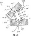
图6A和6B分别示出根据本发明另一个实施例的链节系统的直的和弯曲的(构型的)剖视图,其中包括沿轴向对齐的相对的凹口的相邻链节被设置在所述凹口之间的套管分隔开;6A and 6B show straight and curved (configured) cross-sectional views, respectively, of a chain link system according to another embodiment of the present invention, wherein adjacent links comprising axially aligned opposing notches are positioned at sleeve spacers between said notches;
图7A和7B分别示出根据本发明又一个实施例的链节系统的直的和弯曲的(构型的)剖视图;7A and 7B show straight and curved (configurational) cross-sectional views, respectively, of a chain link system according to yet another embodiment of the present invention;
图8示出根据本发明另一个实施例的外科针驱动器件的透视图,其中远端链节的位置有所改变;8 shows a perspective view of a surgical needle drive device according to another embodiment of the present invention, wherein the position of the distal link is changed;
图9A和9B示出根据本发明另一个实施例的链节锁定机构分别处于锁定位置(9A)和解锁位置(9B)的侧视图;9A and 9B show side views of a link locking mechanism in a locked position (9A) and an unlocked position (9B), respectively, according to another embodiment of the present invention;
图10A示出图9A的锁定机构的俯视图;Figure 10A shows a top view of the locking mechanism of Figure 9A;
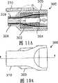
图11A和11B示出图9A的锁定机构的剖视图;11A and 11B show cross-sectional views of the locking mechanism of FIG. 9A;
图12A和12B示出分别用区域C和D指示的图9A和9B的锁定机构的放大剖视图;Figures 12A and 12B show enlarged cross-sectional views of the locking mechanism of Figures 9A and 9B indicated by regions C and D, respectively;
图13示出根据本发明另一个实施例的锁定机构的透视图;Figure 13 shows a perspective view of a locking mechanism according to another embodiment of the present invention;
图14示出图13的锁定机构的侧视图;Figure 14 shows a side view of the locking mechanism of Figure 13;
图15示出图13的锁定机构的俯视图;Figure 15 shows a top view of the locking mechanism of Figure 13;
图16示出图13的锁定机构的端视图;Figure 16 shows an end view of the locking mechanism of Figure 13;
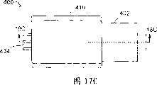
图17A-17C示出处于解锁位置(图17A)、部分锁定位置(图17B)和锁定位置(图17C)的图13的锁定机构的俯视图;17A-17C show top views of the locking mechanism of FIG. 13 in an unlocked position (FIG. 17A), a partially locked position (FIG. 17B) and a locked position (FIG. 17C);
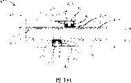
图18A-18C分别示出图17A-C所示的锁定机构分别沿由线18A-18A、18B-18B和18C-18C表示的平面的剖视图;Figures 18A-18C show cross-sectional views of the locking mechanism shown in Figures 17A-C along planes represented by
图19示出根据本发明另一个实施例的链节锁定机构的透视图;Figure 19 shows a perspective view of a link locking mechanism according to another embodiment of the present invention;
图20A和20B示出分别处于锁定构型(20B)和解锁构型(20A)的图19的机构垂直于其纵向轴线剖切的横截面视图;Figures 20A and 20B show a cross-sectional view of the mechanism of Figure 19 taken perpendicular to its longitudinal axis in a locked configuration (20B) and an unlocked configuration (20A), respectively;
图21A和21B分别示出构造为中性缆线偏置(neutral cable bias)的根据本发明另一个实施例的链节系统的直的和弯曲的(构型的)剖视图;21A and 21B show straight and curved (configured) cross-sectional views, respectively, of a link system according to another embodiment of the invention configured as a neutral cable bias;
图22A和22B分别示出构造为负的缆线偏置的根据本发明又一个实施例的链节系统的直的和弯曲的(构型的)剖视图;22A and 22B show straight and curved (configured) cross-sectional views, respectively, of a link system according to yet another embodiment of the invention configured for negative cable bias;
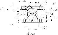
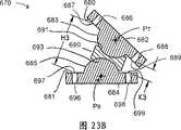
图23A和23B分别示出构造为正的缆线偏置的根据本发明再一个实施例的链节系统的直的和弯曲的(构型的)剖视图。23A and 23B show straight and curved (configured) cross-sectional views, respectively, of a link system according to yet another embodiment of the present invention configured for positive cable bias.
具体实施方式Detailed ways
如文中的更详细说明,提供了可形成或并入或构成多种装置的铰接链节系统和机构。链节系统可由各个链节的组合形成。根据本发明的铰接机构通常包括多对链节和至少一组连接至少一对分离的链节的缆线。文中使用的术语“链节”是指链节系统或铰接机构的分离部分,该分离部分能够相对于该系统或机构的另一个分离部分运动。在一些实施例中,链节可对应于位于机构的相对端的另一个分离部分或限定区域。链节通常为筒状,但并非必须如此。链节通常沿机构的纵向轴线对齐。在一些实施例中,链节系统可包括多个链节,至少两个链节通过套管分隔开。As described in greater detail herein, articulation link systems and mechanisms are provided that may form or incorporate or constitute a variety of devices. A chain link system can be formed from a combination of individual chain links. Articulation mechanisms according to the invention generally include pairs of links and at least one set of cables connecting at least one pair of separate links. As used herein, the term "link" refers to a system of links or a discrete part of an articulation mechanism that is movable relative to another discrete part of the system or mechanism. In some embodiments, a link may correspond to another separate portion or defined area at an opposite end of the mechanism. The links are usually barrel shaped, but need not be. The links are generally aligned along the longitudinal axis of the mechanism. In some embodiments, the link system may include a plurality of links, at least two of which are separated by bushings.
链节系统可形成或并入多种铰接机构。在许多实施例中,根据本发明的铰接机构一般包括多对链节和多组缆线。在另外的实施例中,铰接机构包括多个链节或部段,它们都是分离的成对构件。链节形成近端和远端,而每对中的一个链节位于在近端的链节系统内,而该链节对中的另一个链节位于在远端的链节系统内。Link systems can form or incorporate a variety of articulation mechanisms. In many embodiments, articulation mechanisms according to the present invention generally include multiple pairs of links and multiple sets of cables. In other embodiments, the articulation mechanism includes a plurality of links or segments that are separate pairs of members. The links form the proximal and distal ends, with one link of each pair located within the proximal link system and the other link of the link pair located within the distal link system.
在这种铰接机构中,每个缆线组使铰接机构中分离的一对链节相互连接,使得一对链节中的一个链节的运动引起该对中的另一个链节的相应运动。如文中所用,术语“主动(active)链节”或“主动链节对”是指通过缆线组直接相连的链节。术语“间隔(spacer)链节”或“间隔链节对”是指不通过缆线组直接相连的链节。但是,间隔链节可设置在主动链节之间,并为连接主动链节的缆线组提供通路。能够操作主动链节对的能力使得机构可容易地形成复杂的三维构型和几何形状,下文中将对此作详细说明。对于依赖于以不同方式穿过未连接的链节的缆线组或丝线的传统铰接装置,难以实现这种复杂的几何形状,这是因为这种装置通常设计成使操纵缆线或丝线穿过每个链节并终止于最远端的链节处。因此,所有部段协同响应丝线或缆线组的通常为弯曲或弓形方式的运动而一起弯曲。In such an articulation, each cable set interconnects a separate pair of links in the articulation such that movement of one link of a pair causes corresponding movement of the other link of the pair. As used herein, the term "active link" or "active link pair" refers to links that are directly connected by a cable set. The term "spacer link" or "spacer link pair" refers to links that are not directly connected by a cable set. However, spacer links may be positioned between the drive links and provide passage for the cable sets connecting the drive links. The ability to manipulate pairs of drive links allows the mechanism to be readily formed into complex three-dimensional configurations and geometries, as described in more detail below. Such complex geometries are difficult to achieve with conventional articulations that rely on sets of cables or wires that pass through unconnected links in different Each link terminates at the most distal link. Thus, all segments flex together in concert in response to movement of the wire or cable set, typically in a bending or arcuate manner.
本发明的链节系统或铰接机构可例如结合在用于将手术或诊断器械和工具引导和操纵到病人身体区域内的目标位置的装置中。该装置能够以其自然的、直的构型,或者在从病人之外的位置在其近端进行各种操作之后被引入。在许多实施例中,链节系统形成铰接机构的一部分或几部分。机构近端的运动导致远端处的运动。此外,所引起的远端的定向运动可根据近端相对于远端的旋转程度而被反向、镜像或产生别的结果。另外,近端提供了用于控制对远端的操纵和操作的用户接口,这使用起来更加方便和容易。该用户接口使得例如使用者能够基于设置在外部的近端用户接口的被操作后的形状而容易地看到位于例如病人体内的机构远端的形状和定向运动。可选择地,远端链节的控制或致动可通过更传统的操纵链节致动缆线的方法例如通过使用旋钮和滑轮系统等来实现。The link system or articulation mechanism of the present invention may, for example, be incorporated in devices for guiding and manipulating surgical or diagnostic instruments and tools to target locations within a patient's body region. The device can be introduced in its natural, straight configuration, or after various manipulations have been performed on its proximal end from a location outside the patient. In many embodiments, the link system forms part or parts of the articulation mechanism. Movement at the proximal end of the mechanism results in movement at the distal end. Furthermore, the resulting directional movement of the distal end may be reversed, mirrored, or otherwise produced depending on the degree of rotation of the proximal end relative to the distal end. In addition, the proximal end provides a user interface for controlling the manipulation and operation of the far end, which is more convenient and easy to use. The user interface enables eg a user to easily see the shape and orientation of the distal end of the mechanism located eg in a patient based on the manipulated shape of the externally disposed proximal user interface. Alternatively, control or actuation of the distal links may be accomplished by more traditional methods of manipulating link actuation cables, such as by using a knob and pulley system or the like.
除了形成复杂构型之外,本发明还允许通过限制被操作的主动链节并允许这样的链节抵抗由横向施加的力导致的运动来增加机构的刚性。如果在操作给定的链节对以获得期望形状并将该对的一个链节固定成该期望形状时,该对的另一个链节可抵抗负荷并同时保持其所期望的无负荷形状,则可认为该链节对被完全限制。对于以三个自由度自由运动的链节,至少需要三条缆线来完全限制该链节。而传统的铰接装置并不总是如此。间隔链节不会这样被限制,并且在希望被致动机构具有刚性较弱部分的许多情况下包括这种未被限制的链节是有利的。In addition to forming complex configurations, the present invention allows for increased rigidity of the mechanism by constraining the active links being manipulated and allowing such links to resist movement caused by laterally applied forces. If, when a given pair of links is manipulated to obtain a desired shape and one link of the pair is fixed in that desired shape, the other link of the pair can resist the load while maintaining its desired unloaded shape, then The link pair can be considered fully constrained. For a link that is free to move in three degrees of freedom, at least three cables are required to fully constrain the link. And that's not always the case with conventional articulations. Spacer links are not so constrained, and the inclusion of such unconstrained links is advantageous in many cases where it is desired to have a less rigid portion of the actuated mechanism.
术语“器械”和“工具”在此可互换使用,并且是指通常由使用者操作以实现特定目的的装置。仅为了说明的目的,将在用于在被远程访问的身体区域内的外科或诊断工具和器械的远程引导、操作和/或致动的范围内对本发明的链节系统和铰接机构进行说明。如前所述,还可想到链节系统和铰接机构的除了外科或诊断应用之外的其它应用,并且这对于本领域的技术人员而言是显而易见的。通常,任何这种应用包括希望将器械或工具导引到不易于用手导引或者会存在危险的工作空间中的任何情况。这包括而不限于工业应用,例如用于将工具、探针、传感器等导引到受限的空间内,或者用于工具的远程精确操纵,例如机器的组装或维修。这还可包括工具或器械的应用目标位置难以到达的商业或家用情况。其它情况可包括例如工作环境对于使用者而言是危险的工业应用,例如工作空间暴露在危险化学物质中。其它情况还可包括例如使用者会有危险的法律执行或军事应用,例如将工具或器械部署在危险的或敌对的位置。其它应用还包括仅希望对复杂几何形状进行远程操纵的应用。这些应用包括诸如玩具或游戏的消遣或娱乐中的使用,例如木偶、玩偶、小雕像等的远程操纵。The terms "instrument" and "tool" are used interchangeably herein and refer to a device that is generally manipulated by a user to accomplish a specific purpose. For purposes of illustration only, the link system and articulation mechanism of the present invention will be described in the context of use for remote guidance, manipulation and/or actuation of surgical or diagnostic tools and instruments within remotely accessed body regions. As previously mentioned, other applications of the link system and articulation mechanism than surgical or diagnostic applications are also conceivable and will be apparent to those skilled in the art. In general, any such application includes any situation where it is desired to guide an instrument or tool into a workspace where manual guidance is not easy or would present a hazard. This includes, without limitation, industrial applications, such as for guiding tools, probes, sensors, etc. into confined spaces, or for remote precise manipulation of tools, such as assembly or repair of machines. This can also include commercial or domestic situations where the target location of the tool or appliance is difficult to reach. Other situations may include, for example, industrial applications where the working environment is hazardous for the user, eg the working space is exposed to hazardous chemicals. Other situations may include, for example, law enforcement or military applications where the user would be at risk, such as deploying a tool or implement in a dangerous or hostile location. Other applications include those that simply wish to remotely manipulate complex geometries. These applications include use in recreation or entertainment such as toys or games, such as remote manipulation of puppets, dolls, figurines, and the like.
参照图1A,示出本发明的结合有根据本发明的铰接机构和链节系统的一个实施例。如图1A所示,针驱动器100包括具有被细长轴102隔开的近端链节组104和对应的远端链节组106的铰接机构102,所述细长轴保持近端和远端链节组处于分隔开的关系,并且还形成用于使针驱动器前进的工作轴。具有抓紧夹爪108、109的针驱动工具107附装在远端链节组106的远端,并可操作地连接到棘轮手柄110,该手柄附装在近端链节组104的近端。尽管该实施例结合有针驱动工具,但是容易理解,多种外科工具和器械能够可操作地附装在远端,包括但不限于多普勒流量计、麦克风、内窥镜、光源、探针、牵开器、解剖器、缝合器、夹具、抓紧器、剪刀或切割器,或者消融或烧灼元件,以及如前所述的用于非外科应用的其它工具或器械。Referring to Figure 1A, one embodiment of the present invention incorporating a hinge mechanism and link system according to the present invention is shown. As shown in FIG. 1A ,
如图3A-5中更详细地示出,近端和远端链节组104和106包括对应的成对的链节,即近端链节组104内的每个单独的链节与远端链节组106内的单独链节成对以形成一系列分离的对。远端链节组106包括链节122A、124A和126A,而近端链节组104包括链节122B、124B和126B。链节122A和122B、124A和124B以及126A和126B均为分离的链节对。近端链节(122B、124B和125B)通过缆线组134、135连接到远端链节(122A、124A和126A),使得近端链节组104内的近端链节的运动引起远端链节组106的对应的相关运动。具体地,链节122A和122B通过缆线134连接,链节124A和124B通过缆线135连接,而链节126A和126B固定在细长轴112上。因此,链节122A和122B以及链节124A和124B形成主动链节对。一般而言,使用一组或多组缆线来连接根据本发明的变化实施例的铰接机构的主动链节对。如前所述,在铰接机构的一端的每个主动链节通过形成缆线组的两条或多条缆线连接至在另一端的与其对应的链节。如所述,一个主动链节对的运动由其相应的缆线组控制,并独立于任意其它的主动链节对。As shown in more detail in FIGS. 3A-5 , proximal and distal link sets 104 and 106 include corresponding pairs of links, that is, each individual link within proximal link set 104 is associated with a distal end link set 104 . Individual links within link set 106 are paired to form a series of separate pairs. Distal link set 106 includes links 122A, 124A, and 126A, while proximal link set 104 includes links 122B, 124B, and 126B. Links 122A and 122B, 124A and 124B, and 126A and 126B are all separate link pairs. Proximal links (122B, 124B, and 125B) are connected to distal links (122A, 124A, and 126A) by cable sets 134, 135 such that movement of proximal links within proximal link set 104 causes distal The corresponding relative movement of the
图2A-D更详细地示出类似于与装置100分隔开的链节组106的链节组。如图可见,相邻的链节122和124被套管130分隔开,而相邻的链节124和126被套管132分隔开。从图2C中更清楚地看到,每个链节沿链节组的纵向轴线X1对齐,相邻的链节122和124以及相邻的链节124和126各具有沿该轴线对齐的相对的凸起部(123、125、127、129)。每个套管130和132具有用于接纳链节122、124和126的凸起部的相对的凹部(131、133、137、139)。链节还包括允许缆线组134和135通过的通道138。缆线组134和135分别连接到链节122和124。缆线通道偏离链节的中心轴线,使得当向一条或多条缆线施加张力时,链节122、124和126的凸起部可在每个套管(130和132)的对应凹部内旋转,从而使每个链节围绕枢转点枢转,并允许链节组作为一个整体弯曲,如图2D中可更清楚地示出。每个链节和套管还分别包括中心通道140和141,这些中心通道与每个链节或套管的中心轴线对齐。在被组装时,这些通道形成中央腔,致动缆线(148)从该中央腔通过以便控制和/或致动针驱动工具(107)。中心通道通常还为与同本发明的链节系统或铰接机构一起使用的任意期望工具或器械相关联的缆线、丝线、光纤或其它类似元件提供通道。如图所示,套管130和132的中心通道以截头圆锥142的形状终止。这使得链节和套管能彼此相对枢转而不会影响致动缆线通过。截头圆锥部分的总尺寸通常与链节和套管之间的所期望的相对枢转程度相称。尽管由于上述原因设置中心通道是有利的,但是可理解,链节和套管也可不具有这样的通道,并且对与本发明的链节系统或铰接机构相关联的工具或器械的控制还可通过使致动缆线和其它类似元件沿任意径向位置-包括链节系统或铰接机构的周边-穿过而实现。2A-D illustrate a link set similar to link set 106 spaced apart from
转到图3A-5,上述装置100包括设置在近端链节组104和远端链节组106之间的细长轴112。该轴通常是空心的并且包括空腔114,该空腔容纳连接链节对的缆线组134和135以及致动缆线148。轴的空腔通常为与同本发明的链节系统或铰接机构一起使用的任意期望工具或器械相关联的缆线、丝线、光纤或其它类似元件提供通道。Turning to FIGS. 3A-5 , the
驱动器100的手柄110是传统的棘轮型手柄,该手柄可操作地链接到致动缆线148。具体地,如图3A、3B和5所示,手柄110包括固定臂151和枢转臂152,臂151通过套环153固定在近端链节122B上,套环153与链节122B的互补毂部(reciprocal hub)相接合。枢转臂152在枢轴150处可枢转地连接到固定臂151,并且还包括销147,该销被接纳在臂151的导槽149内并且可在该导槽内平移。致动缆线148在其近端终止于缆线连接器146的远端,缆线连接器146还在其近端接纳销147。当手柄110被致动时,臂152围绕枢转点150枢转,从而引起缆线连接器146和致动缆线148朝装置的近端平移(即缩回)。The
如图4中清楚地示出,针驱动器107类似地通过套环153固定在远端链节122A上,该套环与链节122A的互补毂部分121A相接合。夹爪108和109向远端延伸,并且夹爪108固定,而夹爪109在枢轴105处可枢转地连接至夹爪108。缆线连接器154在其远端在销106处连接到夹爪108,而致动缆线148的远端固定在缆线连接器154的近端上。如图所示,弹簧156围绕缆线148设置并设置在缆线连接器154和远端链节122A之间,使缆线保持张紧并使夹爪109处于打开位置。针驱动器通过中央缆线148的缩回而被致动,该缩回使连接器154缩回并压缩弹簧156,使夹爪109围绕枢轴105枢转到紧靠夹爪108的闭合位置。As best shown in FIG. 4 ,
在本发明的不同实施例中,链节组或链节系统设计成根据每个链节和套管的构造而具有“中性缆线偏置”。当链节系统由于缆线沿链节的一侧施加的致动力而弯曲时,穿过链节的缆线的相对张紧度能够以正的、负的或中性的方式被影响。此影响或偏置也可称为“缆线牵引偏置(pull bias)”。当链节被铰连时产生或增加缆线张紧的链节系统被称作具有“正偏置”。或者,当链节被铰连时导致缆线张紧减小或松弛的链节系统被称作具有“负偏置”。使缆线张紧和缆线松弛最小的链节系统被称作具有“中性偏置”。结合了具有中性缆线偏置的链节系统的机构通常可在一定的运动范围上保持其形状,并可抵抗向该机构施加的会损害形状精度的反作用力,因此通常在大多数情况下是优选的。但是,根据应用,负的或正的偏置或影响可以是有利的。例如,在一些应用中,可使缆线松弛的负的缆线偏置是所期望的,因为这会减小铰接链节的刚性,并限制它们对于沿链节施加的反作用力的抵抗力。期望获得此效应的示例包括导引链节通过或围绕敏感或脆弱的解剖结构的情况。在其它应用中,可使缆线张紧增加的正的缆线偏置是所期望的,因为这会增加铰接链节的刚性并且还增加它们对所施加的反作用力的抵抗力。这种张紧还可提高阻碍链节的进一步弯曲或铰接的抵抗力。期望获得此效应的示例包括预防链节系统的过大弯曲或“过度弯曲”比较重要的应用。In various embodiments of the invention, the link set or link system is designed to have a "neutral cable bias" depending on the configuration of each link and bushing. As the link system bends due to the actuation force exerted by the cable along one side of the link, the relative tension of the cable passing through the link can be affected in a positive, negative or neutral manner. This effect or bias may also be referred to as "cable pull bias." Link systems that create or increase cable tension when the links are articulated are said to have a "positive bias". Alternatively, link systems that result in reduced or loose cable tension when the links are articulated are said to have a "negative bias." A link system that minimizes cable tension and cable slack is said to have a "neutral bias". A mechanism incorporating a link system with a neutral cable offset typically retains its shape over a range of motion and resists reaction forces applied to the mechanism that would impair shape accuracy, so typically in most cases is preferred. However, depending on the application, a negative or positive bias or influence can be advantageous. For example, in some applications, a negative cable bias that causes cable slack is desirable because it reduces the stiffness of articulating links and limits their resistance to reaction forces applied along the link. Examples where this effect is desired include guiding links through or around sensitive or delicate anatomical structures. In other applications, a positive cable bias that results in increased cable tension is desirable as this increases the stiffness of the articulation links and also increases their resistance to applied reaction forces. Such tensioning may also increase resistance to further bending or articulation of the link. Examples where this effect is desired include applications where preventing excessive bending or "overbending" of the link system is important.
参照图2A-2D,链节组106内的链节和套管的特定构造实现了中性缆线偏置。在该实施例中对于实现中性缆线偏置而言很重要的是每个链节-套管-链节组件之间的枢转点的设置和位置。链节122、124和126的凸起部(123、125、127、129)是半球形,而套管130和132的凹部(131、133、137、139)为截头半球形。凸起部和凹部的半球形状在相邻链节之间形成枢转点P。枢转点位于链节组的中心轴线X与由每个链节122、124和126的平的、未突出的轴向面120限定的平面的交点处,并与半球形凸起部围绕其被限定(circumscribe)的轴线点(axis point)相关联。这可参照图2E和2F更清楚地看到,图中示出与图2A-2D内所示的构造类似的链节-套管-链节组件。此处,链节122c和124c同样被套管130c分隔开。链节122c和124c分别包括半球形凸起部123c和125c,这些凸起部被套管130c的截头半球形凹部131c和133c接纳。该构造也在两个链节之间形成枢转点P1、P2,这些枢转点位于轴线X与由每个链节的轴向面120c限定的平面的交点处。另外,链节具有相同的总直径,对应的缆线通道具有相同的半径或与链节中心的距离,以及相同的相邻链节之间的距离或间隙,所述距离或间隙由置于链节之间的套管保持。Referring to FIGS. 2A-2D , the particular configuration of the links and bushings within the link set 106 achieves a neutral cable bias. Important to achieving neutral cable bias in this embodiment is the placement and location of the pivot points between each link-bushing-link assembly. The raised portions (123, 125, 127, 129) of
当链节被操纵到期望位置或构型时,链节-套管-链节组件的每个链节围绕其相应的枢转点枢转,使得任意两个相邻的链节围绕双枢转点相互接近或远离地枢转。此外,由于任意给定链节的这种双枢转行为,给定缆线通道出口点朝相邻链节上的与之对应的缆线通道出口点运动的距离等于该链节的相对侧上的相对缆线通道出口点运动远离相邻链节上的与之对应的缆线通道出口点的距离。但是,不管链节是否枢转,对应的两组缆线通道出口点之间的组合距离保持恒定,这对于保持中性缆线偏置是重要的。当这种组合距离不相等时,缆线松弛或张紧会增加。具体地,当链节枢转或被铰接时在成组的相对缆线出口点之间的组合距离大于处于直的、未铰接位置时的组合距离的情况下,缆线会张紧。或者,当枢转或被铰接时在成组的相对通道出口点之间的组合距离相对于直的、未铰接位置时减小的情况下,缆线会松弛。When the links are manipulated into the desired position or configuration, each link of the link-sleeve-link assembly pivots about its corresponding pivot point such that any two adjacent links pivot about a double The points pivot towards or away from each other. Furthermore, due to this double pivoting behavior of any given link, a given cable channel exit point moves toward its corresponding cable channel exit point on an adjacent link a distance equal to that on the opposite side of that link. The relative cable channel exit point moves away from the corresponding cable channel exit point on the adjacent link. However, regardless of whether the links are pivoted, the combined distance between the corresponding two sets of cable channel exit points remains constant, which is important to maintain neutral cable bias. When this combined distance is not equal, cable slack or tension increases. Specifically, where the combined distance between sets of opposing cable exit points when the links are pivoted or articulated is greater than in the straight, unarticulated position, the cable will be tensioned. Alternatively, where the combined distance between groups of opposing channel exit points is reduced when pivoted or articulated relative to the straight, un-articulated position, the cable will slack.
该现象可参照图21A-23B更清楚地进行说明,图中示出具有中性(图21A-21B)、负的(图22A-22B)和正的(图23A-23B)缆线偏置的链节组件(610,640,670)。每个链节组件(610,640,670)包括两个相邻的链节(622和624,652和654以及682和684),并且在这两个链节之间插有套管(630,660,690)。与上述实施例类似,链节包括凸起部(623,625,653,655,683和685),这些凸起部与套管的凹部(631,633,661,663,691,693)相接合。图21A和21B的链节组件610的构造与图2E和2F内所示的组件类似,并且可实现中性缆线偏置。凸起部623和625为半球形并且接纳在截头半球形的凹部631和633内。和图2A-2F的组件一样,该构造也形成枢转点P3和P4,这些枢转点位于轴线X1与由两个链节(622,624)的轴向面(620,621)限定的平面的交点处,并且与缆线通道(626,628,636,638)的缆线通道出口点(627,629,637,639)一致(coincidewith)。如图所示,链节622的出口点627和629位于链节622的相对侧上,并且在组件处于直的、未弯曲位置(图21A)时与相邻链节624上的出口点637和639对齐。在此位置,出口点627和637之间的距离与出口点629和639之间的距离相同,并且在图21A内用G1表示。当组件弯曲(图21B)时,对应的出口点之间的相对距离改变,如图21B内的距离H1和K1所示。但是,对于如上所述地定位的枢转位置P3和P4,当链节处于直的、未弯曲位置时相对的缆线通道出口点之间的组合距离保持相同。即,G1+G1等于H1+K1,这可用等式G1+G1=H1+K1表示。This phenomenon can be more clearly illustrated with reference to Figures 21A-23B, which show chains with neutral (Figures 21A-21B), negative (Figures 22A-22B) and positive (Figures 23A-23B) cable offsets Section components (610, 640, 670). Each link assembly (610, 640, 670) includes two adjacent links (622 and 624, 652 and 654, and 682 and 684) between which a bushing (630, 660, 690). Similar to the previous embodiments, the links include protrusions (623, 625, 653, 655, 683 and 685) which engage recesses (631, 633, 661, 663, 691, 693) of the bushings . The
图22A-22B内所示的链节组件640设计成实现负的缆线偏置,以便在铰接时增加缆线松弛。除了链节652和654具有从链节652和654的轴向面650、651更远地延伸处的半球形凸起部653和655之外,该组件的链节和套管与图21A-21B内的相同。结果,形成枢转点P5和P6,这些枢转点不再分别与缆线通道656、658、666和668的缆线通道出口点657、659、667和669一致。而是枢转点沿靠近套管660的方向与轴向面偏离一距离y2。在该构型中,当枢转时相对的缆线通道出口点之间的组合距离不等于当链节处于直的、未弯曲位置时相应缆线通道出口点之间的组合距离。即,H2+K2不等于G2+G2,而是等于一更小的值,这会向系统内引入缆线松弛。这可由等式G1+G1=H2+K2+Δ2表示,其中引入系统中的缆线松弛的程度与值Δ2相关。The
相反地,链节组件670(图23A-23B)设计成实现在铰接时可增加缆线张紧的正的缆线偏置。同样,该组件的链节和套管与图21A-21B内的相同,但是链节682和684具有被截短的半球形凸起部683和685。这使得形成枢转点P7和P8,这些枢转点从由链节的轴向面680、681限定的平面偏离一距离y3,但是这次是沿远离套管690的方向偏离。因此,枢转点同样没有与对应缆线通道686、688、696和698的缆线通道出口点687、689、697和699一致。而且,当枢转时相对的缆线通道出口点之间的组合距离不等于在直的、未弯曲位置时相应缆线通道出口点之间的组合距离。而是H3+K3大于G3+G3,这会向系统内引入缆线张紧。这可由等式G3+G3=H3+K3-Δ3表示,其中引入系统中的缆线张紧的程度同样与值Δ3相关。In contrast, the link assembly 670 (FIGS. 23A-23B) is designed to achieve a positive cable bias that increases cable tension when articulating. Again, the links and sleeves of this assembly are the same as in FIGS. 21A-21B , but links 682 and 684 have truncated
中性的、负的和正的缆线偏置还可由多种其它的链节系统构造来实现。作为示例而非限制,图6A和6B内所示的变型示出一种可选构型的链节-套管-链节组件,其可实现与图2A-2D、2E-2F以及21A-21B的链节类似的缆线通道出口点的双枢转和等距运动,并且也会导致中性缆线偏置。链节系统200包括由套管210分隔开的相对的相邻链节202和204。相邻的链节202和204均具有沿轴向对齐的相对的半球形凹部(201、203、205、207)。套管210具有用于分别接纳每个链节202和204的凹部203和205的截头半球形凸起部211、213。链节系统具有两个枢转点P9和P10,这些枢转点位于链节系统的中心轴线X2与分别由链节202和204的轴向面220和222限定的平面的交点处,并且与截头半球形凸起部绕其被限定的轴线点相关联。如参照图6B可具体地看到,套管210的中心通道214的直径分别大于链节202和204的中心通道216、218的直径,以便当链节枢转时允许致动缆线等无阻碍地通过。通过修改组件以引入枢转点位置的偏离,可实现正的或负的偏置。Neutral, negative and positive cable biasing can also be achieved with a variety of other link system configurations. By way of example and not limitation, the variation shown in FIGS. 6A and 6B shows an alternative configuration of a link-sleeve-link assembly that can be implemented in the same manner as in FIGS. 2A-2D, 2E-2F, and 21A-21B. The double pivoting and equidistant movement of the link similar to the cable channel exit point, and also causes the neutral cable bias.
图7A和7B内示出同样可实现中性缆线偏置的另一种链节-套管-链节组件。该系统的链节具有与设置在链节之间的套管相接合的凹部和凸起部。套管同样具有相应的凸起部和凹部。该链节-套管-链节组件同样可实现与图2A-2D的链节以及图6A和6B的链节类似的缆线通道出口点的双枢转和等距运动。链节系统250包括由套管260分隔开的相对的相邻链节252和254。链节252具有半球形凸起部256,而链节254具有与该凸起部256沿轴向对齐的相对的半球形凹部258。套管260具有接纳链节252的凸起部256的截头半球形凹部262,以及由凹部258接纳的截头半球形凸起部264。链节系统250具有两个枢转点P11和P12,这些枢转点位于链节系统的中心轴线X3与由链节252的平的、未凹入也未凸出的轴向面270或链节254的平的、未凹入也未凸出并与套管260相交的轴向面272限定的平面的交点处。这些枢转点还与链节的半球形凸起部或套管的截头半球形凸起部绕其被限定的轴线点相关联。如参照图7B可具体地看到,套管260的中心通道280的直径分别大于链节252和254的中心通道282、284的直径,以便当链节枢转时允许致动缆线等无阻碍地通过。同样,通过修改该组件以引入枢转点位置的偏离,可实现正的或负的偏置。Another link-sleeve-link assembly that also achieves a neutral cable bias is shown in Figures 7A and 7B. The links of the system have recesses and protrusions that engage bushings disposed between the links. The sleeve likewise has corresponding elevations and depressions. This link-sleeve-link assembly also allows for dual pivot and isometric movement of the cable channel exit points similar to the links of Figures 2A-2D and the links of Figures 6A and 6B.
尽管套管的特定实施例已被说明为具有与对应链节的凹部和/或凸起部相接合的凸起部和/或凹部,但是同样可以使用仅为筒状和空心的并具有通常为钝的端部的套管。假设套管的内径稍小于对应的凸起部的直径,或可选地套管的外径稍小于对应的凹部,则这种套管在与对应链节的凸起部和/或凹部接合时也同样能良好地工作,以便链节可相对于套管作枢转运动。Although specific embodiments of bushings have been described as having protrusions and/or recesses that engage with recesses and/or protrusions of corresponding links, it is equally possible to use only cylindrical and hollow and having generally Blunt end of the cannula. Provided that the inner diameter of the sleeve is slightly smaller than the diameter of the corresponding protrusion, or alternatively the outer diameter of the sleeve is slightly smaller than the corresponding recess, such a sleeve when engaged with the protrusion and/or recess of the corresponding link It also works well so that the link can pivot relative to the bushing.
与上述构造和参数一致,根据本发明的链节系统和铰接机构内的链节和套管可根据用途具有任何尺寸和形状。对于外科手术应用,它们的形式通常取决于这些因素例如病人年纪、所关注的解剖区域、预期的应用以及医生的喜好。如所述,链节和套管通常为筒状,并且可包括供将链节连接至其它链节或装置部件的缆线以及与同链节系统一起使用的期望工具或器械相关联的另外的缆线、丝线、光纤或其它类似元件通过的通道。通道直径通常稍大于缆线直径而形成滑动配合。此外,链节还包括一个或多个用于接纳可附装的外科器械或诊断工具的元件或供致动它们的缆线通过的通道。如所述,这些通道可沿链节或套管的中心或周边或任意径向位置定位。根据应用,链节的直径通常为大约0.5mm至大约15mm或更大。套管与链节相比趋向于具有大致相当的尺寸,并常常具有较小的直径。对于内窥镜应用,对于小型内窥镜器械,典型直径可为大约2mm至大约3mm,对于中等尺寸的内窥镜器械,典型直径为大约5mm至大约7mm,而对于大型内窥镜器械,典型直径为大约10mm至大约15mm。对于导管应用,直径可为大约1mm至大约5mm。链节和套管的总长度通常根据链节之间的期望弯曲半径而改变。Consistent with the configuration and parameters described above, the links and bushings within the link system and articulation mechanism according to the present invention can be of any size and shape according to the application. For surgical applications, their form typically depends on such factors as patient age, anatomical region of interest, intended application, and physician preference. As noted, the links and bushings are generally cylindrical in shape and may include cables for connecting the links to other links or device components as well as additional accessories associated with the desired tools or implements for use with the link system. A channel through which cables, wires, optical fibers, or other similar elements pass. The channel diameter is usually slightly larger than the cable diameter to create a snug fit. In addition, the links also include one or more passages for receiving elements of attachable surgical instruments or diagnostic tools or for the passage of cables for actuating them. As noted, these channels may be positioned along the center or perimeter of the link or bushing or at any radial location. Depending on the application, the links typically have a diameter of about 0.5 mm to about 15 mm or more. The bushings tend to be of roughly comparable size and often have a smaller diameter than the links. For endoscopic applications, typical diameters may range from about 2mm to about 3mm for small endoscopic instruments, about 5mm to about 7mm for medium sized endoscopic instruments, and typically for large endoscopic instruments The diameter is about 10 mm to about 15 mm. For catheter applications, the diameter may be from about 1 mm to about 5 mm. The overall length of the links and bushings generally varies depending on the desired bend radius between the links.
对于外科手术应用,链节或套管或该链节或套管并入其中的机构或装置的其它部件可由任何生物相容材料制成,包括但不限于:不锈钢、钛、钽;和它们的任何合金;以及聚合物例如聚乙烯或其共聚物,聚对苯二甲酸乙二醇酯或其共聚物、尼龙、硅树脂、聚亚胺酯、含氟聚合物、聚(氯乙烯);以及它们的组合。如果希望的话,可在链节或套管或其它部件上设置光滑涂层以便有助于链节系统的前进。光滑涂层可包括亲水聚合物例如聚乙烯吡咯烷酮,含氟聚合物例如四氟乙烯,或硅树脂。还可在一个或多个链节或套管上包含不透射线的标记以便在射线成像时指示铰接机构或装置的位置。通常,将通过荧光检查来检测标记。For surgical applications, the links or sleeves or other parts of the mechanism or device into which they are incorporated may be made of any biocompatible material including, but not limited to: stainless steel, titanium, tantalum; and their Any alloy; and polymers such as polyethylene or its copolymers, polyethylene terephthalate or its copolymers, nylon, silicone, polyurethane, fluoropolymers, poly(vinyl chloride); and their combination. If desired, a lubricious coating may be provided on the links or bushings or other components to aid in the advancement of the link system. The lubricity coating may comprise a hydrophilic polymer such as polyvinylpyrrolidone, a fluoropolymer such as tetrafluoroethylene, or silicone. Radiopaque markers may also be included on one or more links or sleeves to indicate the position of the articulation mechanism or device when radiographically imaged. Typically, labeling will be detected by fluoroscopy.
尽管附图内已示出的许多链节系统具有一定数量的链节和套管,但是这仅是用于说明单个机构或链节和套管组件之间的相互关系。根据这些因素例如铰接机构的预期使用和期望长度以及运动范围,可采用任意数量的链节和套管。While many link systems have been shown in the drawings with a certain number of links and bushings, this is only to illustrate the interrelationship between individual mechanisms or link and bushing assemblies. Any number of links and bushings may be used depending on such factors as the intended use of the articulation mechanism and the desired length and range of motion.
如所述,缆线可用于致动本发明的链节系统。在这些实施例中,一个或多个链节通过两条或多条缆线连接到位于远端的与之对应的链节或部段。每个缆线组可由至少两条缆线构成。如所述,链节的运动由其对应的缆线组控制,并独立于任何其它的链节。在一些变型中,例如,缆线组将包括三条缆线。通过使用一组的三条缆线连接到链节,能以三个自由度(即上/下运动、左/右运动,以及旋转或“滚动”运动)操纵或移动该链节,而独立于任何其它的链节。通过组合多个链节,可实现多个自由度,使得链节系统可成形为多种复杂的构型。例如,图2A内所示的远端链节组106共具有三个链节(122、124、126),其中两个链节(122、124)通过缆线组(134、135)独立地连接,从而能以6个自由度运动。在仅使用一组缆线来操纵链节的典型的传统机构中,不能获得这种多个自由度。As mentioned, cables may be used to actuate the link system of the present invention. In these embodiments, one or more links are connected to a corresponding link or segment at the distal end by two or more cables. Each cable set may consist of at least two cables. As stated, the movement of the links is controlled by their corresponding cable sets and is independent of any other links. In some variations, for example, the cable set will include three cables. By connecting to the link using a set of three cables, the link can be manipulated or moved in three degrees of freedom (i.e., up/down motion, left/right motion, and rotational or "rolling" motion), independent of any other links. By combining multiple links, multiple degrees of freedom can be achieved, allowing the link system to be shaped into a variety of complex configurations. For example, the distal link set 106 shown in FIG. 2A has a total of three links (122, 124, 126), wherein two links (122, 124) are independently connected by a cable set (134, 135). , so that it can move in 6 degrees of freedom. Such multiple degrees of freedom cannot be obtained in typical conventional mechanisms that use only one set of cables to manipulate the links.
缆线直径根据应用而改变,并且可为大约0.15mm至大约3mm。对于导管应用,典型直径可为大约0.15mm至大约0.75mm。对于内窥镜应用,典型直径可为大约0.5mm至大约3mm。The cable diameter varies depending on the application and may be from about 0.15mm to about 3mm. For catheter applications, typical diameters may be from about 0.15 mm to about 0.75 mm. For endoscopic applications, typical diameters may range from about 0.5 mm to about 3 mm.
缆线柔性可例如因缆线材料的类型和编排方式而改变或因物理或化学处理而改变。通常,将根据铰接机构的预期应用的需要而改变缆线刚度或柔性。缆线可以是由这样的材料制成的单股或多股线,所述材料包括但不限于生物相容材料例如镍钛合金、不锈钢或其任何合金、超弹性合金、碳纤维,聚合物例如聚(氯乙烯)、聚氧乙烯、聚对苯二甲酸乙二醇酯和其它聚酯,聚烯烃、聚丙烯,以及它们的共聚物;尼龙;丝(silk);以及它们的组合,或本领域内已知的其它合适的材料。Cable flexibility may change, for example, due to the type and arrangement of cable material or due to physical or chemical treatments. Typically, the cable stiffness or flexibility will be varied as required by the intended application of the articulation mechanism. The cable may be a single or multiple strands of material including, but not limited to, biocompatible materials such as nickel-titanium alloys, stainless steel or any alloy thereof, superelastic alloys, carbon fibers, polymers such as polyester (vinyl chloride), polyoxyethylene, polyethylene terephthalate and other polyesters, polyolefins, polypropylene, and their copolymers; nylon; silk (silk); and combinations thereof, or the art other suitable materials known in the art.
缆线可根据本领域内已知的方式固定在链节上,例如通过使用粘结剂或通过硬钎焊、软钎焊、焊接等,其包括在未决的且共有的美国申请No.10/444,769中所述的方法,该申请全文结合于此作为参考。在图5内所示的实施例中,缆线134通过定位螺丝143固定在链节122B上。The cables may be secured to the links according to known means in the art, such as by use of adhesives or by brazing, soldering, welding, etc., which are included in pending and commonly owned U.S. Application No. 10 /444,769, which application is hereby incorporated by reference in its entirety. In the embodiment shown in FIG. 5 ,
本发明的链节系统和铰接机构还可包括间隔链节即未通过分离的缆线组连接的链节。这些链节用作被动链节,它们不能被独立地致动,但是允许缆线组通过其中而到达邻近的主动链节。间隔链节是在链节系统或铰接机构内提供额外长度所需要的。另外,在机构的一端包括间隔链节使得在对应的另一端的移动或运动可成比例地缩放。例如,在远端和近端的成对链节相连接的铰接机构的近端包括间隔链节需要使用者在近端实施更大的运动以便在远端实现所期望的运动。这在需要精确、精细的受控运动的情况下是有利的,例如在如果远端的移动或运动不能进行这种成比例缩放则存在使用者不能必要地熟练执行所期望过程的危险的情况下。或者,可在远端设置间隔链节,在这种情况下远端的运动程度可成比例地大于近端的运动程度,这也是特定应用所需要的。除了上文所述之外,移动或运动的成比例缩放还可通过增加或减小缆线通道定位处与中心轴线的半径或距离来实现,下文将对此作进一步说明。The link system and articulation mechanism of the present invention may also include spacer links, ie links that are not connected by separate sets of cables. These links act as passive links, which cannot be actuated independently, but allow the cable sets to pass through them to the adjacent active links. Spacer links are needed to provide extra length within a link system or articulation mechanism. In addition, including spacer links at one end of the mechanism allows the movement or motion at the corresponding other end to be scaled proportionally. For example, including spaced links at the proximal end of an articulation mechanism that connects pairs of links at the distal and proximal ends requires the user to perform greater motion at the proximal end in order to achieve a desired motion at the distal end. This is advantageous in situations where precise, finely controlled movements are required, for example where there is a risk that the user will not be able to perform the desired procedure with the necessary proficiency if the movement or movement of the distal end cannot be scaled in this way. . Alternatively, spacer links may be provided at the distal end, in which case the degree of motion of the distal end may be proportionally greater than the degree of motion of the proximal end, as may be desired for a particular application. In addition to the above, scaling of movement or motion can also be achieved by increasing or decreasing the radius or distance from the central axis where the cable channel is located, as will be further explained below.
转到图1A和1B的实施例,近端和远端链节的构造成使近端链节组104的运动引起在远端链节组106处的放大运动。尤其参照图4和5,可见近端链节122B、124B和126B通常大于它们的远端配对链节122A、124A和126A。更重要的是,对于近端链节122B、124B和126B而言,缆线通道(138B)的定位处离对应链节的中心轴线的半径或距离比它们的远端链节配对物(138A)更大。由于该差,给定的链节对在被操作时可产生与该差成比例的交互(reciprocal)运动。对于任何两个链节对,该差可用当链节相对于它们的未枢转状态被操作时所得到的枢转角度来表示。因此,对于任意给定的分别具有不同的缆线通道定位半径R1和R2的链节对L1和L2,并且其中R2>R1,当L1枢转角度A1时,对应的链节L2将产生枢转角A2=A1×sin-1(R1/R2)。因此,缆线通道定位半径的增加或减小可成比例地增加或减小对应的近端和远端链节系统的弯曲角。这可具有重要的人类工程学应用,包括由使用者操作的近端的较小的折曲角会导致远端的较大的弯曲角或折曲角从而使得远端可进行放大或增加的运动以布置和/或致动外科工具或器械的外科手术应用。这具体参照图1B可见,该图示出处于弯曲构型的装置100的链节组104和106。位于远端链节组106的端部的针驱动器107相对于细长轴112的运动角度大约为90度,并且成比例地大于位于近端链节组104的近端的手柄110相对于该轴的角度,该角度示出为大约45度。Turning to the embodiment of FIGS. 1A and 1B , the configuration of the proximal and distal links is such that movement of the proximal link set 104 causes amplified movement at the distal link set 106 . Referring particularly to FIGS. 4 and 5 , it can be seen that the proximal links 122B, 124B, and 126B are generally larger than their distal counterpart links 122A, 124A, and 126A. More importantly, for proximal links 122B, 124B, and 126B, cable channels (138B) are located at a greater radius or distance from the central axis of the corresponding link than their distal link counterparts (138A). bigger. Due to this difference, a given link pair, when manipulated, can produce a reciprocal motion proportional to this difference. For any two link pairs, this difference may be expressed in terms of the pivot angle obtained when the links are operated relative to their unpivoted state. Therefore, for any given link pair L1 and L2 with different cable channel positioning radii R 1 and R 2 , respectively, and whereR 2>R 1, when L1 is pivoted by angle A1 , the corresponding The link L2 of will produce the pivot angle A2 =A1 ×sin-1 (R1 /R2 ). Accordingly, an increase or decrease in the cable channel positioning radius may proportionally increase or decrease the bend angles of the corresponding proximal and distal link systems. This can have important ergonomic applications, including that a smaller flex angle of the proximal end manipulated by the user results in a larger flex or flex angle of the distal end allowing for amplified or increased motion of the distal end Surgical applications to deploy and/or actuate surgical tools or instruments. This can be seen with particular reference to FIG. 1B , which shows link sets 104 and 106 of
在图1和3-6所示的实施例中,手柄110固定在近端链节组104的近端上。在该构型内,手柄本身可用于操纵近端链节,从而对应地操纵远端链节。因此,手柄本身可用于手动操纵和操作远端针驱动器。在图8所示的可选实施例中,针驱动器700包括手柄710,该手柄直接固定在细长轴712的近端上。近端链节组704如前所述地可操作地连接到远端链节组706,但是相关联的链节缆线的路线设置成使得链节组704从手柄本身露出,并且该链节组的最远端的链节固定在手柄上。在该构型内,手柄可操纵或引导细长轴。然后,近端链节组可被独立地操作以便操纵远端的针驱动工具707,这类似于操纵杆。该“操纵杆”构型可增加使用者在某些方向或使用中的控制。In the embodiment shown in FIGS. 1 and 3-6 , the
链节系统、铰接机构以及结合有这种系统或机构的装置还可包括锁定机构。锁定机构在被致动时可防止一个或多个链节或成对的链节运动。在一个方面中,锁定机构构造成接纳连接到并操纵链节的缆线(或其它类似的致动元件),并且在被致动时,限制缆线(或其它类似的致动元件)运动并由此限制和锁定对应的相连的链节对。在一些变型中,锁定机构包括活动的锁定构件和固定的接触构件,从而活动的锁定构件的运动使缆线(或其它类似的致动元件)与固定的接触构件相接触,从而阻止缆线(或其它类似的致动元件)进一步运动,进而还阻止链节的运动。所述的锁定机构与文中公开的链节和链节系统以及其它链节系统-包括在未决和共有的美国申请No.10/444,769内所述的系统,该申请全文结合于此作为参考-以及其它已知的链节系统兼容。Link systems, articulation mechanisms, and devices incorporating such systems or mechanisms may also include locking mechanisms. The locking mechanism prevents movement of one or more links or pairs of links when actuated. In one aspect, the locking mechanism is configured to receive a cable (or other similar actuation element) connected to and manipulate a link, and when actuated, limit the movement of the cable (or other similar actuation element) and The corresponding pair of linked links is thereby constrained and locked. In some variations, the locking mechanism includes a movable locking member and a fixed contact member, whereby movement of the movable locking member brings the cable (or other similar actuating element) into contact with the fixed contact member, thereby preventing the cable ( or other similar actuating elements) to move further, which in turn also prevents the chain link from moving. The described locking mechanism and the links and link systems and other link systems disclosed herein - including the system described in co-pending and commonly owned U.S. Application No. 10/444,769, which is hereby incorporated by reference in its entirety - and other known link systems.
图9-12示出这样一种锁定机构的实施例。具体参照图11A-11B,锁定机构300在壳体305内包括沿轴向对齐的固定套环302和沿轴向对齐的活动套环304。固定套环302的内表面和活动套环304的外表面为锥形,从而如图所示,活动套环304可部分地接纳在固定套环302内。销312从活动套环304延伸通过壳体305内的狭槽314。杠杆310在枢轴316处枢转地连接到壳体305,此时凸轮318与销312接触。缆线309和308沿机构的纵向轴线对齐。缆线还通过固定套环302被接纳,然后围绕活动套环304的周界布置。在解锁位置,如图9B、11B和12B所示,杠杆310处于竖立位置,大致垂直于机构的轴线。在此位置,在两个套环之间存在足够的间隙以允许缆线自由地移动通过机构,同时在固定套环302和活动套环304之间的摩擦接触最小,这在图12B中更清楚地示出。Figures 9-12 illustrate an embodiment of such a locking mechanism. Referring specifically to FIGS. 11A-11B , the
在锁定位置,如图9A-11A所示,杠杆310向下枢转直到大致平行于锁定机构的中心轴线。该运动导致凸轮318与销312接合并使销312和套环304朝套环302平移。当杠杆处于锁定位置时,销接合棘爪(detent)319而将杠杆保持在锁定位置。由于套环304这样朝套环302运动,所以缆线与套环摩擦接触并基本上被夹紧在两个套环之间,从而摩擦地阻止缆线的进一步运动,还阻止连接到缆线的链节的运动。In the locked position, as shown in FIGS. 9A-11A , the
图13-18示出根据本发明的锁定机构的另一个实施例。在此实施例中,锁定机构400包括具有接纳缆线的通道的壳体402。应理解,壳体还可并入轴部分或者沿铰接机构的其它地方。或者,轴部分本身可形成壳体。滑动件410围绕壳体402,并可相对于壳体沿轴向移动。壳体420还包括沿筒体的中心轴线延伸的中心通道408。如将进一步说明的,滑动件沿中心轴线的方向移动以致动锁定机构。图17A和18A分别示出处于解锁位置的轴向滑动件机构的俯视图和截面图。参照图18A,壳体包括相对于壳体402的中心轴线设置在不同位置的两个锁定通道414和416。按钮件418和424分别设置在锁定通道414和416内。每个按钮件包括头部(421、427),弹簧(420,426)和缆线接触件(422,428)。参照按钮件418,缆线接触件422定位在垂直于中心轴线的通道414内并且在缆线432穿过通道436时接近缆线432。弹簧426具有足够的膨胀力以保持接触件422与缆线轻微地接触,而头部421与滑动件410的内侧接触,同时仍允许缆线432以最小的阻力自由地穿过通道436。按钮件424类似地安置在通道416内,并在缆线436穿过通道438时相对于缆线436类似地定向。13-18 illustrate another embodiment of a locking mechanism according to the invention. In this embodiment,
如图18A-18C最清楚地看出,滑动件410包括滑动件的内径较大以使得在滑动件和壳体402之间形成空隙的区域,以及滑动件的内径较小以使得仅在滑动件和壳体之间具有很小间隙的区域。这些区域沿直线对齐以与锁定通道(的位置)重合。当轴向滑动件机构400处于完全解锁位置(图17A和18A)时,滑动件410定位成使得空隙区域与锁定通道414和416对齐。在完全解锁位置,没有按钮件对相应的相关联缆线施加足够的力以摩擦地阻止缆线的运动。因此缆线(432、434)可在它们各自的通过通道(436、438)内自由移动,从而引起任何相连接的链节系统(未示出)的相应运动。As best seen in FIGS. 18A-18C ,
通过沿锁定机构400的轴线移动滑动件410来致动锁定机构400。图17B和18B示出机构400处于部分锁定位置,其中缆线434被锁定而缆线432还可自由移动。参照图18B,可以看到滑动件410已被定位成使得最小间隙区域与锁定通道416重合。结果,滑动件沿锁定通道416向按钮件424的头部427施加增加的径向力,该径向力可克服弹簧426的膨胀力,使得缆线接触件428以增加的力按压在缆线434上并发生与通道438的内壁的摩擦接触。缆线434的进一步平移被阻止,连接到缆线434的链节(未示出)的任何进一步运动也同样被阻止。但是,在该相同构造中,滑动件410仍具有与锁定通道414重合的空隙区域,从而缆线432仍可在通过通道436内自由平移,由此与缆线432相关联的链节保持为可运动。最终结果是,缆线434的平移运动摩擦地阻止,但是缆线432的运动未受阻止,从而部分地锁定相关联的链节系统(未示出)。The
图17C和18C示出处于完全锁定位置的锁定机构400。参照图18C,滑动件410定位成最小间隙区域与锁定通道414和416都重合,从而两个缆线接触件(422,428)和按钮件(418,424)被按压在它们对应的缆线(432,434)上,使得缆线与它们对应的通过通道(436、438)的内壁摩擦接触,从而摩擦地阻止缆线和任何相关联的链节的平移运动。从该实施例可理解,通过分离的缆线组连接的不同链节或链节对可具有与每组缆线相关联的锁定通道,这些通道围绕沿壳体轴线的指定位置沿径向定向。当滑动件相对于壳体沿轴向移动时,这些链节或链节对可被依次锁定或解锁。例如在希望将链节系统的一部分锁定就位而其它部分仍保持自由以便可进一步操纵、引导、导向或致动远端工具或器械的情况下,能够依次锁定或解锁相连的链节或链节对的能力是有利的。此外,无需限制链节组的所有缆线来有效地锁定相连的链节对。例如,对于具有三条缆线的缆线组,仅需要限制两条缆线以便进行有效锁定。17C and 18C show the
图19-20内示出根据本发明的锁定机构的另一个实施例。锁定机构500包括被共轴的锁定环510和512所围绕的筒状壳体502。锁定环510和512可围绕壳体502旋转,并且其作用与图13-18的实施例中的滑动件410类似。当锁定环510和512旋转到指定位置时,接纳通过壳体502的一条或多条缆线的移动被阻止。另外,壳体本身可集成于铰接机构的轴部分或沿该机构的其它地方,或者轴部分本身可形成壳体。Another embodiment of a locking mechanism according to the invention is shown in Figures 19-20. Locking mechanism 500 includes a
图20A和20B示出相对于缆线519、521、423处于解锁(图20A)和锁定(图20B)构型的锁定机构500。壳体502被同轴的锁定环510所围绕。锁定环510的内侧以及该筒体的外周不具有均匀的匹配直径,而是具有渐缩(tapered)空隙部分,在两个渐缩空隙部分之间散置有最小间隙部分。筒体502包括围绕筒体502沿径向设置在不同位置的三个锁定通道518、520和522。每个锁定通道(518、520、522)与穿过接纳相关联的缆线(519、521、523)的通道的缆线相关联。应理解,剩余的所示的缆线将与沿该壳体位于不同轴向位置的锁定环和锁定通道相关联。与图13-18的实施例中的那些按钮件类似,这里的按钮件具有类似构造并且位于它们对应的通道内,其中每个按钮件(526、534、540)具有头部(527、535、541)、弹簧(528、532、538)以及缆线接触件(529、533、539)。还参照图20A,当锁定机构处于解锁构型时,锁定环510定位成使每个按钮件(526、534、540)都与空隙区域对齐,从而按钮都没有被足够大的力压下以使相关联的缆线(519、521、523)与它们相应的通过通道的内壁摩擦接触,以便阻止缆线移动。因此,在该解锁位置,缆线(519、521、523)可自由地平移通过筒体502。20A and 20B illustrate locking mechanism 500 in an unlocked ( FIG. 20A ) and locked ( FIG. 20B ) configuration relative to
图20B示出通过围绕筒体502旋转锁定环510而使该机构运动到锁定构型。当锁定环510被旋转到锁定构型时,每个按钮(526、534、540)都与锁定环510和筒体502之间的最小间隙区域重合。与图13-19内的实施例相类似,这也类似地导致每个按钮(526、534、540)被克服相关联的弹簧件(528、532、538)的足够大的力压进锁定通道内,并将它们的相关联的缆线接触件(529、533、539)沿径向推动压靠在它们的相关联缆线(519、521、523)上,使相关联的缆线与它们的相关联的通过通道的内壁摩擦接触。这样,摩擦地阻止缆线(519、521、523)进一步平移通过筒体502,从而将缆线以及与缆线相连接的任何链节锁定就位。从该实施例可理解,通过分离的缆线组连接的不同的链节或链节对也可具有与每组缆线相关联的锁定通道,这些通道围绕沿与单个锁定环相关联的筒体的指定位置沿径向定向。因此可独立地锁定或解锁这些链节或链节对中的每一个。能够独立地锁定或解锁相连的链节或链节对的能力可具有许多优点,包括如前文所述的希望将链节系统的一部分锁定就位而其它部分仍保持自由以便可进一步操纵、引导、导向或致动远端工具或器械的情况。FIG. 20B shows the movement of the mechanism to the locked configuration by rotating the
根据用途,锁定机构可以为任何尺寸和形状,但是它们的尺寸和形状通常与任何相关联的链节系统、铰接机构或结合有这种系统或铰接机构的装置类似。类似于链节系统本身,锁定机构通常但非必须地为筒状,并且可包括供将锁定机构连接至装置的其它部件的缆线以及与同该锁定机构一起使用的期望工具或器械相关联的另外的缆线、丝线、光纤或其它类似元件通过的通道。在包括缆线的锁定机构的实施例中,缆线通道直径通常稍大于缆线直径而形成滑动配合。此外,锁定机构还可包括一个或多个用于接纳可附装的外科器械或诊断工具的元件或供致动它们的缆线通过的通道。Depending on the application, the locking mechanisms may be of any size and shape, but they are generally similar in size and shape to any associated link system, articulation mechanism or device incorporating such a system or articulation mechanism. Similar to the link system itself, the locking mechanism is usually, but not necessarily, cylindrical in shape and may include cables for connecting the locking mechanism to other parts of the device as well as cables associated with the desired tool or instrument for use with the locking mechanism. A channel through which additional cables, threads, optical fibers, or other similar elements pass. In embodiments of the locking mechanism that include a cable, the cable channel diameter is typically slightly larger than the cable diameter to form a snug fit. In addition, the locking mechanism may also include one or more elements for receiving attachable surgical instruments or diagnostic tools or passages for the cables that actuate them.
在一些实施例中,锁定机构可设置在链节系统或铰接机构的一端。在另外的实施例中,锁定机构可设置在外科器械的近端或远端的任何位置处。尽管附图内示出的多种锁定机构具有一定的构型和一定数量的部件,但是这仅用于说明部件之间的相互关系。根据这些因素例如锁定机构的预期使用,可采用任何数量的部件。In some embodiments, the locking mechanism may be provided at one end of the link system or articulation mechanism. In additional embodiments, the locking mechanism may be located anywhere on the proximal or distal end of the surgical instrument. Although the various locking mechanisms shown in the drawings have a certain configuration and a certain number of components, this is only for illustrating the interrelationship of the components. Any number of components may be used depending on such factors as the intended use of the locking mechanism.
本发明还包括用于提供各种链节系统、铰接机构、锁定机构以及相关联的附件的成套工具。例如,可提供包含具有不同长度、不同部段直径的链节系统和铰接机构,和/或不同类型的工具或器械的成套工具。成套工具可任选地包含不同类型的锁定机构。成套工具还可针对特定应用而进行进一步定制。例如,用于外科手术应用的成套工具可构造成用于例如内窥镜检查、回缩或导管安置和/或用于特定的病人群体例如儿童或成人。The present invention also includes a kit for providing various link systems, articulation mechanisms, locking mechanisms and associated accessories. For example, kits may be provided that include link systems and articulation mechanisms having different lengths, different segment diameters, and/or different types of tools or instruments. The kit can optionally contain different types of locking mechanisms. Kits can also be further customized for specific applications. For example, a kit for surgical applications may be configured for use in endoscopy, retraction, or catheter placement, for example, and/or for a particular patient population, such as children or adults.
Claims (49)
Translated fromChineseApplications Claiming Priority (5)
| Application Number | Priority Date | Filing Date | Title |
|---|---|---|---|
| US57775704P | 2004-06-07 | 2004-06-07 | |
| US60/577,757 | 2004-06-07 | ||
| US10/928,479US7828808B2 (en) | 2004-06-07 | 2004-08-26 | Link systems and articulation mechanisms for remote manipulation of surgical or diagnostic tools |
| US10/928,479 | 2004-08-26 | ||
| PCT/US2005/018146WO2005120327A2 (en) | 2004-06-07 | 2005-05-23 | Link systems and articulation mechanisms for remote manipulation of surgical or diagnostic tools |
Related Child Applications (1)
| Application Number | Title | Priority Date | Filing Date |
|---|---|---|---|
| CN201210027026.6ADivisionCN102525659B (en) | 2004-06-07 | 2005-05-23 | Link systems and articulation mechanisms for remote manipulation of surgical or diagnostic tools |
Publications (2)
| Publication Number | Publication Date |
|---|---|
| CN101048102Atrue CN101048102A (en) | 2007-10-03 |
| CN101048102B CN101048102B (en) | 2012-04-04 |
Family
ID=38772155
Family Applications (2)
| Application Number | Title | Priority Date | Filing Date |
|---|---|---|---|
| CN2005800251530AExpired - Fee RelatedCN101048101B (en) | 2004-06-07 | 2005-05-23 | Articulation mechanism with flexibly articulated links |
| CN2005800251545AExpired - Fee RelatedCN101048102B (en) | 2004-06-07 | 2005-05-23 | Link systems and articulation mechanisms for remote manipulation of surgical or diagnostic tools |
Family Applications Before (1)
| Application Number | Title | Priority Date | Filing Date |
|---|---|---|---|
| CN2005800251530AExpired - Fee RelatedCN101048101B (en) | 2004-06-07 | 2005-05-23 | Articulation mechanism with flexibly articulated links |
Country Status (1)
| Country | Link |
|---|---|
| CN (2) | CN101048101B (en) |
Cited By (17)
| Publication number | Priority date | Publication date | Assignee | Title |
|---|---|---|---|---|
| CN102905632A (en)* | 2011-03-03 | 2013-01-30 | 奥林巴斯医疗株式会社 | Endoscope Treatment Instruments |
| CN104093372A (en)* | 2012-04-02 | 2014-10-08 | Movasu公司 | Minimally invasive surgical instrument having articulation immobilising structure |
| CN102341053B (en)* | 2009-01-09 | 2015-01-07 | 恩杜森斯公司 | Fiber optic force sensing catheter |
| CN107666873A (en)* | 2014-12-05 | 2018-02-06 | 微创手术医疗器械公司 | The method of instrument can be manipulated for manufacturing and this manipulates instrument |
| CN108685557A (en)* | 2017-04-06 | 2018-10-23 | 香港中文大学 | The hand-held end of the endoscope system and the endoscope system |
| CN109431599A (en)* | 2018-11-21 | 2019-03-08 | 深圳市罗伯医疗科技有限公司 | A kind of flexible joint mechanism |
| CN110900654A (en)* | 2019-12-13 | 2020-03-24 | 中国科学院沈阳自动化研究所 | Inflatable flexible light mechanical arm |
| CN111166995A (en)* | 2020-02-21 | 2020-05-19 | 四川大学华西医院 | Urinary catheter intubation aid |
| CN111513851A (en)* | 2015-03-10 | 2020-08-11 | 柯惠Lp公司 | Robotic surgical system, instrument drive unit and drive assembly |
| CN113232042A (en)* | 2020-01-23 | 2021-08-10 | 通用电气公司 | Selective flexible extension tool |
| CN115644774A (en)* | 2022-12-29 | 2023-01-31 | 安徽库派医疗科技有限公司 | Position detection type endoscope with electromagnetic coil sensing structure |
| CN116616904A (en)* | 2023-06-19 | 2023-08-22 | 苏州视通医疗科技有限公司 | A control mechanism and medical device for a flexible robotic arm |
| US12091981B2 (en) | 2020-06-11 | 2024-09-17 | General Electric Company | Insertion tool and method |
| US12194620B2 (en) | 2018-10-15 | 2025-01-14 | Oliver Crisipin Robotics Limited | Selectively flexible extension tool |
| US12264591B2 (en) | 2019-01-14 | 2025-04-01 | General Electric Company | Component repair system and method |
| US12405187B2 (en) | 2019-10-04 | 2025-09-02 | General Electric Company | Insertion apparatus for use with rotary machines |
| US12416800B2 (en) | 2021-01-08 | 2025-09-16 | General Electric Company | Insertion tool |
Families Citing this family (31)
| Publication number | Priority date | Publication date | Assignee | Title |
|---|---|---|---|---|
| CN103961050B (en)* | 2008-04-18 | 2016-09-28 | 福蒂美迪克斯外科医疗器材有限公司 | A kind of instrument for endoscopic applications |
| WO2009127236A1 (en)* | 2008-04-18 | 2009-10-22 | Fortimedix B.V. | An instrument for endoscopic applications or the like |
| CN101653353B (en)* | 2009-08-28 | 2010-12-01 | 哈尔滨工业大学 | Continuum semi-autonomous endoscopic robot |
| ES2874194T3 (en) | 2009-12-16 | 2021-11-04 | Boston Scient Scimed Inc | Arrangements for making an endoluminal anatomical structure |
| US10531869B2 (en) | 2009-12-16 | 2020-01-14 | Boston Scientific Scimed, Inc. | Tissue retractor for minimally invasive surgery |
| US10758116B2 (en) | 2009-12-16 | 2020-09-01 | Boston Scientific Scimed, Inc. | System for a minimally-invasive, operative gastrointestinal treatment |
| US10595711B2 (en) | 2009-12-16 | 2020-03-24 | Boston Scientific Scimed, Inc. | System for a minimally-invasive, operative gastrointestinal treatment |
| US8932211B2 (en) | 2012-06-22 | 2015-01-13 | Macroplata, Inc. | Floating, multi-lumen-catheter retractor system for a minimally-invasive, operative gastrointestinal treatment |
| US12376737B1 (en) | 2009-12-16 | 2025-08-05 | Boston Scientific Scimed, Inc. | Tissue retractor for minimally invasive surgery |
| US11344285B2 (en) | 2009-12-16 | 2022-05-31 | Boston Scientific Scimed, Inc. | Multi-lumen-catheter retractor system for a minimally-invasive, operative gastrointestinal treatment |
| US9565998B2 (en) | 2009-12-16 | 2017-02-14 | Boston Scientific Scimed, Inc. | Multi-lumen-catheter retractor system for a minimally-invasive, operative gastrointestinal treatment |
| CN102169228B (en)* | 2011-04-12 | 2012-11-28 | 应启迪 | Adjustable endoscope |
| CN103085083B (en)* | 2013-01-07 | 2015-06-24 | 汪雯 | Flexible continuous body mechanical structure capable of bending and stretching |
| JP5979640B2 (en) | 2013-02-26 | 2016-08-24 | 株式会社神戸製鋼所 | Polishing tool |
| KR20160088849A (en)* | 2013-06-09 | 2016-07-26 | 매크로프라타, 아이엔씨. | Multi-lumen-catheter retractor system for a minimally-invasive, operative gastrointestinal treatment |
| CN103707322B (en)* | 2013-12-31 | 2016-04-20 | 汪雯 | Retractable and flexible non-individual body frame for movement can be curved |
| CN104116528A (en)* | 2014-07-14 | 2014-10-29 | 上海交通大学 | Endoscopic surgery instrument outer sheath based on soft continuum mechanism |
| CN105266752A (en)* | 2015-09-08 | 2016-01-27 | 上海熠达光电科技有限公司 | Bending portion of endoscope and disposable endoscope |
| CN105232095B (en)* | 2015-09-28 | 2017-11-21 | 宁波胜杰康生物科技有限公司 | A kind of operating theater instruments of multistage adjustable bending |
| CN105433895A (en)* | 2015-12-16 | 2016-03-30 | 李安 | Endoscope and curved tube thereof |
| CN106236003B (en)* | 2016-08-29 | 2018-12-04 | 辜春霖 | Separated electronic video-endoscope |
| CN107263528A (en)* | 2017-07-21 | 2017-10-20 | 清华大学 | The flexible joint structure of flexible arm |
| CN107280626B (en)* | 2017-08-02 | 2019-05-10 | 李全科 | A medical endoscope |
| CN109278034B (en)* | 2018-10-24 | 2022-04-22 | 哈尔滨工业大学(深圳) | A rope-driven flexible gripper and robot |
| DE102018132165A1 (en)* | 2018-12-13 | 2020-06-18 | Bayerische Motoren Werke Aktiengesellschaft | Storage device and vehicle |
| CN110215240A (en)* | 2019-05-30 | 2019-09-10 | 南开大学 | A kind of end effector mechanism of single-hole laparoscopic surgery |
| US11832789B2 (en) | 2019-12-13 | 2023-12-05 | Boston Scientific Scimed, Inc. | Devices, systems, and methods for minimally invasive surgery in a body lumen |
| CN112757278B (en)* | 2021-01-19 | 2024-09-20 | 广西大学 | Snake-shaped movement mechanism |
| EP4035584B1 (en)* | 2021-01-28 | 2023-10-18 | Ambu A/S | Endoscope comprising an articulated bending section body |
| CN113199461B (en)* | 2021-05-24 | 2022-12-27 | 山东大学 | Construction operation mechanical arm based on flexible continuum and auxiliary operation device |
| CN119770182B (en)* | 2024-12-31 | 2025-10-03 | 武汉大学 | Neurosurgery minimally invasive surgery-oriented continuum robot |
Family Cites Families (4)
| Publication number | Priority date | Publication date | Assignee | Title |
|---|---|---|---|---|
| US5325845A (en)* | 1992-06-08 | 1994-07-05 | Adair Edwin Lloyd | Steerable sheath for use with selected removable optical catheter |
| US5759151A (en)* | 1995-06-07 | 1998-06-02 | Carnegie Mellon University | Flexible steerable device for conducting exploratory procedures |
| IT1277690B1 (en)* | 1995-12-22 | 1997-11-11 | Bieffe Medital Spa | VERTEBRAL SUPPORT AND IMPLEMENTATION SYSTEM IN PARTICULAR FOR SURGICAL AND DIAGNOSTIC INSTRUMENTS |
| US6491626B1 (en)* | 1999-04-16 | 2002-12-10 | Nuvasive | Articulation systems for positioning minimally invasive surgical tools |
- 2005
- 2005-05-23CNCN2005800251530Apatent/CN101048101B/ennot_activeExpired - Fee Related
- 2005-05-23CNCN2005800251545Apatent/CN101048102B/ennot_activeExpired - Fee Related
Cited By (22)
| Publication number | Priority date | Publication date | Assignee | Title |
|---|---|---|---|---|
| CN102341053B (en)* | 2009-01-09 | 2015-01-07 | 恩杜森斯公司 | Fiber optic force sensing catheter |
| CN102905632B (en)* | 2011-03-03 | 2016-01-20 | 奥林巴斯株式会社 | Endoscope treatment tool |
| CN102905632A (en)* | 2011-03-03 | 2013-01-30 | 奥林巴斯医疗株式会社 | Endoscope Treatment Instruments |
| CN104093372A (en)* | 2012-04-02 | 2014-10-08 | Movasu公司 | Minimally invasive surgical instrument having articulation immobilising structure |
| CN107666873B (en)* | 2014-12-05 | 2020-07-17 | 微创手术医疗器械公司 | Method for producing a steerable instrument and such a steerable instrument |
| CN107666873A (en)* | 2014-12-05 | 2018-02-06 | 微创手术医疗器械公司 | The method of instrument can be manipulated for manufacturing and this manipulates instrument |
| CN111513851B (en)* | 2015-03-10 | 2023-12-12 | 柯惠Lp公司 | Robotic surgical system, instrument drive unit and drive assembly |
| CN111513851A (en)* | 2015-03-10 | 2020-08-11 | 柯惠Lp公司 | Robotic surgical system, instrument drive unit and drive assembly |
| CN108685557A (en)* | 2017-04-06 | 2018-10-23 | 香港中文大学 | The hand-held end of the endoscope system and the endoscope system |
| US12194620B2 (en) | 2018-10-15 | 2025-01-14 | Oliver Crisipin Robotics Limited | Selectively flexible extension tool |
| CN109431599A (en)* | 2018-11-21 | 2019-03-08 | 深圳市罗伯医疗科技有限公司 | A kind of flexible joint mechanism |
| CN109431599B (en)* | 2018-11-21 | 2024-05-10 | 深圳市罗伯医疗科技有限公司 | Flexible joint mechanism |
| US12264591B2 (en) | 2019-01-14 | 2025-04-01 | General Electric Company | Component repair system and method |
| US12405187B2 (en) | 2019-10-04 | 2025-09-02 | General Electric Company | Insertion apparatus for use with rotary machines |
| CN110900654A (en)* | 2019-12-13 | 2020-03-24 | 中国科学院沈阳自动化研究所 | Inflatable flexible light mechanical arm |
| CN113232042A (en)* | 2020-01-23 | 2021-08-10 | 通用电气公司 | Selective flexible extension tool |
| CN111166995A (en)* | 2020-02-21 | 2020-05-19 | 四川大学华西医院 | Urinary catheter intubation aid |
| US12091981B2 (en) | 2020-06-11 | 2024-09-17 | General Electric Company | Insertion tool and method |
| US12416800B2 (en) | 2021-01-08 | 2025-09-16 | General Electric Company | Insertion tool |
| CN115644774A (en)* | 2022-12-29 | 2023-01-31 | 安徽库派医疗科技有限公司 | Position detection type endoscope with electromagnetic coil sensing structure |
| CN116616904A (en)* | 2023-06-19 | 2023-08-22 | 苏州视通医疗科技有限公司 | A control mechanism and medical device for a flexible robotic arm |
| CN116616904B (en)* | 2023-06-19 | 2025-09-02 | 苏州视通医疗科技有限公司 | A control mechanism for a flexible robotic arm and a medical device |
Also Published As
| Publication number | Publication date |
|---|---|
| CN101048101B (en) | 2012-11-14 |
| CN101048102B (en) | 2012-04-04 |
| CN101048101A (en) | 2007-10-03 |
Similar Documents
| Publication | Publication Date | Title |
|---|---|---|
| CN101048102A (en) | Link systems and articulation mechanisms for remote manipulation of surgical or diagnostic tools | |
| JP5665152B2 (en) | Link system and articulation mechanism for remote operation of surgical or diagnostic tools | |
| US11998195B2 (en) | Instrument with multiple articulation locks | |
| US11491310B2 (en) | Articulating mechanism with flex-hinged links | |
| US11638590B2 (en) | Articulating mechanisms and link systems with torque transmission in remote manipulation of instruments and tools | |
| US20060201130A1 (en) | Articulating mechanisms with joint assembly and manual handle for remote manipulation of instruments and tools |
Legal Events
| Date | Code | Title | Description |
|---|---|---|---|
| C06 | Publication | ||
| PB01 | Publication | ||
| C10 | Entry into substantive examination | ||
| SE01 | Entry into force of request for substantive examination | ||
| C14 | Grant of patent or utility model | ||
| GR01 | Patent grant | ||
| CF01 | Termination of patent right due to non-payment of annual fee | Granted publication date:20120404 | |
| CF01 | Termination of patent right due to non-payment of annual fee |