Movatterモバイル変換


[0]ホーム

URL:


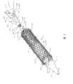
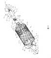
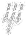
CN101045022B - Self-expanding stent axial wire-drawing tensioning mechanism - Google Patents

Self-expanding stent axial wire-drawing tensioning mechanism
Download PDF

Info

Publication number
CN101045022B
CN101045022BCN2006100252968ACN200610025296ACN101045022BCN 101045022 BCN101045022 BCN 101045022BCN 2006100252968 ACN2006100252968 ACN 2006100252968ACN 200610025296 ACN200610025296 ACN 200610025296ACN 101045022 BCN101045022 BCN 101045022B
Authority
CN
China
Prior art keywords
far
backguy
pipe
interior pipe
open
Prior art date
Legal status (The legal status is an assumption and is not a legal conclusion. Google has not performed a legal analysis and makes no representation as to the accuracy of the status listed.)
Active
Application number
CN2006100252968A
Other languages
Chinese (zh)
Other versions
CN101045022A (en
Inventor
温宁
Current Assignee (The listed assignees may be inaccurate. Google has not performed a legal analysis and makes no representation or warranty as to the accuracy of the list.)
Beijing Bai Ren Medical Polytron Technologies Inc
Original Assignee
Individual
Priority date (The priority date is an assumption and is not a legal conclusion. Google has not performed a legal analysis and makes no representation as to the accuracy of the date listed.)
Filing date
Publication date
Application filed by IndividualfiledCriticalIndividual
Priority to CN2006100252968ApriorityCriticalpatent/CN101045022B/en
Priority to US12/295,059prioritypatent/US20090099640A1/en
Priority to PCT/CN2007/001016prioritypatent/WO2007115483A1/en
Publication of CN101045022ApublicationCriticalpatent/CN101045022A/en
Application grantedgrantedCritical
Publication of CN101045022BpublicationCriticalpatent/CN101045022B/en
Activelegal-statusCriticalCurrent
Anticipated expirationlegal-statusCritical

Links

Images

Classifications

Landscapes

Abstract

An axially pulled stretch mechanism for a self-expanding stents is composed of an internal tube for the scaffold arranging system, an optional intermediate tube, a locking wire, at least one far-end and at least one near-end pull threads with respective pull rings at their far end, and the open fixers and/or closed thread pinholes at both ends of said scaffold. Its application is also disclosed.

Description

Self-expanding stent axial wire-drawing tensioning mechanism
Technical field
The various supports that the present invention relates to a kind of implant into body cardiovascular or other luminal organs relate in particular to a kind of self-expanding stent axial wire-drawing tensioning mechanism at the defeated strainer of letting slip in the journey.
Background technology
Heart is the most important organ of human body, and heart is divided into left and right sides two parts, and each part comprises atrium and ventricle again.Left atrium and left and right ventricles are separated by interatrial septum and interventricular septum respectively.In heart, there are four cardiac valve, i.e. Tricuspid valve, valve of pulmonary trunk, Bicuspid valve and aortic valve.In the blood of human body cycling mechanism, four cardiac valve play crucial effects.The anoxia blood of body cycling mechanism enters right atrium through caval vein, enter right ventricle by Tricuspid valve then, right ventricle shrinks blood is pressed into pulmonary circulation mechanism by valve of pulmonary trunk, get back to left atrium through the blood behind the lung oxygen saturation through pulmonary vein, arrive left ventricle through Bicuspid valve again, the left ventricle contraction enters aorta with blood by aortic valve and returns to the body cycling mechanism.Left and right sides coronary ostium is arranged under the aortic valve.Close when valve-open when four valvular structures have guaranteed blood along direction, contrary direction, prevented blood reflux and the heart burden that causes.But, because a variety of causes can cause valvular posteriority damage or pathological changes, as rheumatism, atherosclerosis etc.In addition, congenital heart disease such as fallot's disease, postoperative also can produce the cusps of pulmonary valve pathological changes long term.Show as valvular function after the valve pathological changes and lose gradually, cause blood reflux as valvular insufficiency, valvular stenosis causes blood circulation not smooth, or incompetence and narrow the two merger, so that increase the weight of the heart burden, causes cardiac failure.For valvular posteriority damage or pathological changes, traditional Therapeutic Method is out breast, after the cardiac arrest, under the cryotron outer circulation is supported, opens heart and carries out the surgical repair of pathological changes valve or use artificial cardiac valve replacement.Existing Cardiac valve prosthesis divides two big classes: metal mechanical valve prosthesis and biovalve.Biovalve is made after being handled by animal materials such as bovine pericardium, bovine jugular vein lobe, porcine aortic valve.The method of above-mentioned open heart operation, operating time is long, the expense height, wound is big, has a big risk, and metal mechanical valve prosthesis displacement back patient needs long-term anticoagulant therapy, and the material lifetime of biovalve is limited, needs operation more usually.
In order to solve the problem that above-mentioned open heart operation treatment cardiac valve exists, existing now people attempts not doing open heart operation, and adopts percutaneous interventional method or the defeated Cardiac valve prosthesis of putting of Minimally Invasive Surgery.The Cardiac valve prosthesis of prior art comprises balloon-expandable stent valve and self expandable type stent valve.But self expandable type stent valve is provided with the support of a radial deformation, can expand voluntarily after the radial compression.Self expandable type stent valve must carry out the radial compression of protectiveness to stent valve earlier in that intravascular is defeated when being put in the human body, and defeated being put into allows its expansion behind the position again.Therefore must design a cover and compress mechanism, this strainer can be made radial compression with it before putting so that fail and put in that stent valve is defeated, fails at stent valve and can remove compression easily after being put into the position, allows the stent valve rapid release expand.
Have following three kinds of different ways that self-expanding stent, self-extending type overlay film frame, self-expanding stent valve are carried out radial compression at present, make it diameter and diminish, Wicresoft easy to use mode is imported in the body.
A), sheath pipe
Self-expanding stent, self-extending type overlay film frame, self-expanding stent valve etc. by radial compression in the thin sheath pipe of a lateral seal.Thin sheath pipe can be by polytetrafluoroethylene (PTFE), perfluoroethylene-propylene making such as (FEP), self-expanding stent radial dilatation under the resilience force effect of itself when the sheath pipe is return.The shortcoming of this method is: 1, the sheath pipe of the defeated place system of existing self-expanding stent and the support under the radial compression are harder, and bendability is poor.2, frictional force is big between the sheath pipe of self-expanding stent and its defeated place system, influences the accurate release of support; Self-expanding stent is under high compression, and the rollback of sheath pipe can run into very big resistance; Move back the resistance of sheath pipe and the support displacement that difficulty also can make the operator locate.3, the thin sheath pipe of lateral seal hinders the guide wire side direction and from inside to outside or from outside to inside passes support under the radial compression, even there is lateral openings to allow seal wire pass through on the sheath pipe, but the seal wire overslaugh sheath pipe that side direction is passed returns, and allows the self-expanding stent can not radial dilatation.4, in order to reach certain mechanical strength, the thin sheath tube thickness minimum of using is 0.20 to 0.30mm at present, makes radial compression lower carriage and induction system increasing diameter add at least 0.40 to 0.60mm.
B), the outer peelable film of support
Comprise:
B1), be permanently affixed at peelable film on the support.At the support external fixation one film that can vertically tear is arranged.But the dyestripping longitudinal opening is a light wall pipe when closing up, its inner support warp-wise compression.But during the strip off of dyestripping longitudinal opening, it is to the support restriction cancellation, and its inner support warp-wise is expanded.But it is identical with stent length to be somebody's turn to do dyestripping, and tearable film length can not change in compression of support warp-wise and process of expansion, flows to side shoot through support but dyestripping can hinder blood.
B2), the outer peelable film of removable support
The bendability of above-mentioned peelable film and radial compression lower carriage has improvement slightly than (a).But still have following shortcoming: 1, peelable film obstruction seal wire side direction from inside to outside or is from outside to inside passed the support under the radial compression; The opening part that the unique position that can pass of side direction seal wire is peelable film, but the side direction seal wire is limited on this unique anglec of rotation.2, be fixed on after peelable film on the support torn, the support radial dilatation, if length shortens after the support radial dilatation, peelable film length is constant but greater than radial dilatation after-poppet length, long film hinders blood flow.3, be fixed on after peelable film on the support torn, support is radial dilatation under self elastic force effect, and circumference increases, on each cross section, the peelable membrane portions that is fixed on the support covers rack outer surface, makes blood side direction inflow collateral blood vessels from here.This hinders support to use at some position, and to coronary ostium, the thoracic aorta overlay film frame is to the carotid artery opening as aortic valve stent, and the ventral aorta overlay film frame is to left and right sides renal artery opening etc.
C), the defeated place system of support cluster
This method has used a kind of softish line 365 degree to be looped around on the support, makes line lower carriage radial compression (referring to Chinese patent 20040054347.0).Compare with preceding two kinds of methods, this is very successful improvement.But still have following shortcoming: 1, support is only online around locating radial compression, if support is longer, the compression of support overall radial is not enough, or needs much to locate around line, and this makes structure become very complicated; Or needing thin sheath pipe further radial compression outside support simultaneously, this makes it lose its open structural advantage.If 2, around line only outside support around, have from the danger of support two end portions slippage; If inside and outside support, shuttle back and forth,, but increase with the frictional force of support just not by the danger of slippage around line.
In addition, also there is following problem in the defeated place system of prior art in that self-expanding stent is failed when putting:
1, location difficulty: the hard bendability of the defeated place system of existing insertion type stent valve and the stent valve under the radial compression is poor, through behind the aortic arch, can not aim at nature aortic valve mouth.The axial upstream and downstream location of insertion type stent valve and its defeated place system and direction of rotation location are not easy because of unstable the becoming of the artificial valve under the blood flow impact.
2, change in location: under the self-expanding stent valve high compression, the rollback of conventional sheath pipe can run into very big resistance.Move back the resistance of sheath pipe and the man-made support valve displacement that difficulty also can make the operator locate; In dispose procedure, stent valve partly is expanded to full expansion gradually, and required time surpasses a heart beat cycle.The stent valve of expansion can hinder blood flow, and stent valve also can make its position change because of blood flow impacts.
3, the position is adjusted: self-expanding stent is radially fully after the expansion, as the position not to or improper, the position of self-expanding stent can not be adjusted again.These inappropriate positions can be the errors along support longitudinal axis upstream and downstream; Can be around support longitudinal axis rotation error; Also can be that the support longitudinal axis becomes angle error with vessel axis.
4, support reclaims: after self-expanding stent was radially expanded fully, not right as the size and the size of support, inappropriate support can not reclaim.
Summary of the invention
Purpose of the present invention, be to solve the prior art self-expanding stent radial compression is defeated put in the problems referred to above of existence, a kind of self-expanding stent axial wire-drawing tensioning mechanism is provided.
The object of the present invention is achieved like this: a kind of self-expanding stent axial wire-drawing tensioning mechanism is used for this support of axial tensioning when self-expanding stent is implanted cardiovascular; Described self-expanding stent be can radial deformation pipe type netted structure, surround a plurality of deformables unit between each netting twine of support, the two ends of support form a plurality of open lines and turn and can be provided with a plurality of closed line eyes; Described self-expanding stent can carry out implanting cardiovascular release after the radial compression with multiple open defeated place system, described defeated place system comprises interior pipe or middle pipe, near-end controller, backguy and lock silk also can be arranged, the far-end of interior pipe is connected with interior tube head, an interior pipe section far away outside selectivity is connected with the lateral guide fiber tube, middle pipe box can slide along interior pipe outside interior pipe, the near-end controller is connected the near-end of interior pipe and middle pipe and is provided with interior pipe near-end backguy mouth and middle pipe near-end backguy mouth, in being arranged on, the lock silk in the pipe or in the interlayer between the interior Guan Yuzhong pipe, is characterized in:
Described axial backguy strainer comprises the interior pipe that is used to form defeated place system, or manage in also can having and the lock silk, the open line at support two ends turn or and closed line eye, and the backguy that is used for the tensioning support, the tube head near-end is provided with at least one proximal open in described, the distally of pipe section far away and nearside are respectively equipped with at least one distal openings and at least one proximal open in described, pipe is provided with a distal openings or also at least one distal openings can be arranged in described, described backguy comprises at least one far-end backguy that links to each other with rack far end and at least one near-end backguy that links to each other with mount proximal end, the far-end of each backguy is respectively equipped with a stay thimble, each backguy its far-end stay thimble locked the silk provisional pass pinning after, the opening of tube head or interior pipe or middle pipe in passing, respectively the open line of rack far end or near-end turn or closed line eye between pass through and constitute the provisional connection of support, formation can be carried out the backguy strainer of axial tensioning to support.
Described far-end backguy and near-end backguy respectively are one, the far-end backguy is after its far-end stay thimble is blocked by the lock silk in the interior pipe, a side opening of tube head or a distal openings of interior pipe in passing, one to two open line walking around rack far end again turns or a closed line eye, constitutes the provisional connection of rack far end; The near-end backguy is after its far-end stay thimble is blocked by the lock silk between interior pipe or the interior Guan Yuzhong pipe, a proximal open of pipe or a distal openings of middle pipe in passing, one to two open line walking around mount proximal end again turns or a closed line eye, constitutes the provisional connection of mount proximal end; The open line that described far-end backguy and near-end backguy are walked around turns or closed line eye can be on the same ordinate of support, and certain angle also can stagger.
Described far-end backguy and near-end backguy respectively are two, two far-end backguys are after its far-end stay thimble is blocked by the same or different lock silks in the interior pipe respectively, a side opening of tube head or the same or different distal openings of interior pipe in passing, one to two open line walking around rack far end more respectively turns or a closed line eye, constitutes two provisional connections of separate rack far end; Two near-end backguys are after its far-end stay thimble is blocked by the lock silk between interior pipe or the interior Guan Yuzhong pipe respectively, a proximal open of pipe or a distal openings of middle pipe in passing respectively, one to two open line walking around mount proximal end more respectively turns or a closed line eye, constitutes two provisional connections of separate mount proximal end; The open line that described two far-end backguys are walked around turns or closed line eye is positioned at the relative both sides of rack far end, the open line that described two near-end backguys are walked around turns or closed line eye is positioned at the relative both sides of mount proximal end, and the open line of walking around with two far-end backguys respectively turns or closed line eye one by one corresponding to the same ordinate of support or about 90 degree that interlace.
Described far-end backguy and near-end backguy respectively are three, three far-end backguys are after its far-end stay thimble is blocked by the same or different lock silks in the interior pipe respectively, a side opening of tube head or the same or different distal openings of interior pipe in passing, one to two open line walking around rack far end more respectively turns or a closed line eye, constitutes three provisional connections of separate rack far end; Three near-end backguys are after its far-end stay thimble is blocked by the lock silk between interior pipe or the interior Guan Yuzhong pipe respectively, same or the different proximal open or the same or different distal openings of middle pipe of pipe in passing respectively, one to two open line walking around mount proximal end more respectively turns or a closed line eye, constitutes three provisional connections of separate mount proximal end; The open line that described three far-end backguys are walked around turns or closed line eye equal angles is distributed in the far-end of support, the open line that described three near-end backguys are walked around turns or closed line eye equal angles is distributed in the near-end of support, and the open line of walking around with three far-end backguys respectively turns or closed line eye one by one corresponding to the same ordinate of support or about 60 degree that interlace.
Described far-end backguy and near-end backguy respectively are one, the far-end backguy is after its far-end stay thimble is blocked by the lock silk in the interior pipe, a side opening of tube head or a distal openings of interior pipe in passing, one to two open line walking around rack far end again turns or a closed line eye, other one to two open line of walking around rack far end again turns or another closed line eye, constitutes the provisional connection of rack far end secondary; The near-end backguy is after its far-end stay thimble is blocked by the lock silk between interior pipe or the interior Guan Yuzhong pipe, a proximal open of pipe or the distal openings of middle pipe in passing, one to two open line walking around mount proximal end again turns or a closed line eye, other one to two open line of walking around mount proximal end again turns or another closed line eye, constitutes the provisional connection of mount proximal end secondary; The open line that described far-end backguy secondary is walked around turns or closed line eye is positioned at the relative both sides of rack far end, the open line that described near-end backguy secondary is walked around turns or closed line eye is positioned at the relative both sides of mount proximal end, and two open lines walking around with far-end backguy secondary respectively turn or two closed line eyes one by one corresponding to the same ordinate of support or about 90 degree that interlace.
Described far-end backguy after constituting the provisional connection of rack far end, can from same or different in the pipe distal openings enter interior pipe, or enter between support and the interior pipe, then from interior pipe near-end backguy mouth or therefrom manage near-end backguy mouth and come out; Described near-end backguy is after constituting the provisional connection of mount proximal end, can enter interior pipe from same or different interior pipe proximal open, or therefrom manage distal openings or distal openings enter between pipe and the interior pipe, then from interior pipe near-end backguy mouth or pipe near-end backguy mouth come out.
Described two or three far-end backguys can be respectively from interior pipe near-end backguy mouth or pipe near-end backguy mouth come out and control respectively, make rack far end be the asymmetry expansion; Described two or three near-end backguys can be respectively from interior pipe near-end backguy mouth or pipe near-end backguy mouth come out and control respectively, make mount proximal end be the asymmetry expansion.
Described two or three far-end backguys can be between provisional connection of rack far end and backguy near-end synthetic Anywhere bus, by the bus of regulation and control far-end backguy, can make rack far end be the symmetry expansion; Described two or three near-end backguys can be between provisional connection of mount proximal end and backguy near-end synthetic Anywhere bus, by the bus of regulation and control near-end backguy, can make mount proximal end be the symmetry expansion; By drawing or put the bus of far-end backguy or the bus of near-end backguy respectively, can make rack far end or near-end be the asymmetry expansion.
The near-end of a described far-end backguy can lump together with the near-end of a near-end backguy, draws the near-end of a line can control far-end backguy and near-end backguy simultaneously, make support to two end axles to tensioning.
The bus of the bus of described each far-end backguy and each near-end backguy can connect together, and can spur or loosen all far-end backguys and near-end backguy by drawing or putting a bus, make support almost symmetry at two ends by axial tensioning or loosen.
Pipe distal direction control line in also comprising, this distal direction control line can slide outside the lock silk backguy intracavity of interior pipe or interior pipe, and its far-end and interior pipe far-end are fixedly linked, and manage near-end in its near-end passes and are free shape.
Self-expanding stent axial wire-drawing tensioning mechanism of the present invention makes it compared with prior art owing to adopted above technical scheme, has following advantage and characteristics:
1, rack far end and near-end are passed in the far away/near-end backguy in the self-expanding stent axial wire-drawing tensioning mechanism of the present invention respectively, can only pass once, and be not outer around support.Far/part that the near-end backguy is arranged in the tube outside is in almost parallel with the support longitudinal axis or a pipe longitudinal axis plane or eclipsed axial plane.Far/the near-end backguy at the support two ends vertically to after drawing, can be with the support axially-extending.When the single line braided support is carried out axially-extending also with radial compression.Backguy is positioned at the part of pipe the inside and the part of tube outside is in same plane.
2, each far away/near-end backguy can be identical or have nothing in common with each other at the tension force of support one end.Support one end and interior pipe or middle pipe layout comparatively speaking, expansion and adjustment can be symmetry or asymmetry.
3, after the support under the radial compression puts in place, far/the near-end backguy or and the help of interior pipe distal direction control line under, the axial angle direction of support can fine control.
4, support is fast from the process that is compressed to full expansion, only need unclamp far away/near-end backguy of tension or forward (far-end) push away middle pipe.
5, after support is expanded fully, before final release, can be recompressed, further expansion, the position can be adjusted again.
6, inappropriate expandable stent before final release, might be recovered.
7, each far away/near-end backguy is located in one plane always, and friction is low during slip.
Description of drawings
Fig. 1 is the three-dimensional perspective that self-expanding stent axial wire-drawing tensioning mechanism of the present invention and flexible connection ring compressing mechanism are used;
Fig. 2 is the three-dimensional perspective that self-expanding stent axial wire-drawing tensioning mechanism of the present invention and wire intaking compacting mechanism are used;
Fig. 3 is the three-dimensional perspective of self-expanding stent axial wire-drawing tensioning mechanism of the present invention and associated fitting (oneself removes other radial compaction mechanism) thereof;
Fig. 4 is the three-dimensional perspective of self-expanding stent axial wire-drawing tensioning mechanism of the present invention and associated fitting (oneself loosens backguy, the support radial dilatation) thereof;
Fig. 5 is the three-dimensional perspective of self-expanding stent axial wire-drawing tensioning mechanism of the present invention and associated fitting (fixedly the lock silk of backguy is own removes) thereof;
Fig. 6 a, Fig. 6 b, Fig. 6 c are the sectional structure sketch map of self-expanding stent axial wire-drawing tensioning mechanism one embodiment of the present invention and associated fitting thereof, and wherein Fig. 6 b, Fig. 6 c are the different connected modes of Fig. 6 a in the near-end backguy of mount proximal end;
Fig. 7 a, Fig. 7 b, Fig. 7 c are the sectional structure sketch map of self-expanding stent axial wire-drawing tensioning mechanism one embodiment of the present invention and associated fitting thereof, and wherein Fig. 7 b, Fig. 7 c are the different connected modes of Fig. 7 a in the near-end backguy of mount proximal end;
Fig. 8 a, Fig. 8 b, Fig. 8 c are the sectional structure sketch map of self-expanding stent axial wire-drawing tensioning mechanism one embodiment of the present invention and associated fitting thereof, and wherein Fig. 8 b, Fig. 8 c are the different connected modes of Fig. 8 a in the near-end backguy of mount proximal end;
Fig. 9 is the sectional structure sketch map of self-expanding stent axial wire-drawing tensioning mechanism one embodiment of the present invention and associated fitting thereof,
The specific embodiment
Referring to Fig. 1 to Fig. 9, self-expanding stent axial wire-drawing tensioning mechanism of the present invention is used for cooperating defeated place system and this support of various support hold-down mechanism tensioning thereof when self-expanding stent is implanted cardiovascular.Support hold-down mechanism wherein comprises the inventor's flexible connection ring compressing mechanism and wire intaking compacting mechanism (referring to two other patent application of the inventor: " self-extending type bracket flexible connection ring compressing mechanism " and " wire intaking compacting mechanism for self-expanding stent ").
Related self-expanding stent 1 comprises self-extending type overlay film frame and self-expanding stent valve among the present invention, the part of the cradle wall of self-extending type overlay film frame or all be coated with overlay film 11.The cradle wall of self-expanding stent valve partly or all be coated withoverlay film 11, the support internal fixation have can switchvalve leaflet 12, make blood unidirectional by (referring to Fig. 1 to Fig. 5).
Self-expanding stent be can radial deformation pipe type netted structure single line braided support particularly, by elastomeric material such as memorial alloy (Nitinol), cochrome formations such as (Phynox).Self-expanding stent structurally can be divided into far-end and near-end, near-end and far-end for the patient, from the patient near be called near-end, from the patient far away be called far-end (each parts in the corresponding defeated place system are also told far-end and near-end by this regulation).Self-expanding stent can be under external force by radial compression, radial dilatation automatically after external force is removed.Surround a plurality ofdeformables unit 101 between each netting twine of self-expanding stent, the two ends of support form a plurality of open lines andturn 102, the support two ends or and the middle part be provided with a plurality ofclosed line eyes 103, form a plurality ofcross points 104 between each netting twine of support.Self-expanding stent can be formed by the line braiding, also can be formed by tubing cutting distortion.Litzendraht wire can be single also can many, preferred single elasticity litzendraht wire, the upper-lower position of its adjacent intersections place litzendraht wire is just in time opposite.Support can be monolayer support or the inside and outside double-layer scaffold that free tongue is arranged.Support also can be the branch support.
Can be connected with flexible connection ring compressing mechanism 105 (referring to Fig. 1) or wire intaking compacting mechanism 106 (referring to Fig. 2) on the related self-expanding stent 1 among the present invention, flexible connection ring wherein and take-up are formed by the deformable line braiding of softness, as polyester thread (DACRON), polyethylene line (POLYETHYLENE), nylon wire (PA), polypropylene line (POLYPROPYLENE) etc.
Pipe 2,lock silk 3, backguy 4,middle pipe 5 and near-end controller 6 in related defeated place system comprises among the present invention.
Interior pipe 2 is an elongated pipe, can be crooked.Color preferably clear or translucent.In pipe a circle 0.035 is arranged in 2 "guidewire lumen 21 and one or morelock backguy chamber 22 lead to near-end from far-end.Different backguy 4 and locksilk 3 can slide in the lock silk backguy chamber 22.Interior pipe 2 sections far away are provided with side opening (distal openings 231, proximal open 232) from far near at least one cross section, lead to one or more lock backguy chamber 22.These side openings can be at same or different cross section, and opening is towards same or different directions.Distance between far and near two cross sections is more than or equal to the length of radial compression lower carriage 1.Can there be one to three side opening in each cross section.Angle on the same cross section between two or more side openings is known, as 120 degree.
The far-end of interior pipe is connected with taper or streamlined interior tube head 7.Interior tube head 7 far-ends have thethick guidewire lumen 21 of seal wire opening 71 and interior pipe to communicate, and interior tube head middle part has flushing opening 72 to communicate with interior Guan Suosi backguy chamber 22.Interior tube head 7 near-ends can be provided with one or more side opening 73 on same cross section or different cross section.In the present invention,pipe distal openings 231 used in theside opening 73 on the interior tube head can replace.Interior pipe section far away goes up alternative and has lateral guide fiber tube 8.Lateral guide fiber tube or seal wire can come out to a plurality of direction openings on same cross section.The pore size of lateralguide fiber tube 8 can allow 0.014 at least " the diameter seal wire passes through.There is at least onelock silk 3 to slide in the locksilk backguy chamber 22 along interiorpipe.Lock silk 3 near-ends can come out from the near-end controller of defeated place system.Interior pipe far-end alternative is provided with distaldirection control line 41, and (referring to Fig. 6 a, Fig. 7 a), distaldirection control line 41 can or slide outside the interior pipe in the locksilk backguy chamber 22 of interior pipe.The far-end of distaldirection control line 41 and firm being fixed together of interior pipe far-end.The pipe near-end was free shape in the near-end of distal direction control line passed.
Interior pipe 2 near-ends are provided with near-end backguy mouth 24 (referring to Fig. 1 to Fig. 5), and direction and quantity can be identical or different with side opening (73,231,232).The pipe near-end is external in the operation, and other parts can enter in the body.
Pipe 5 outsideinterior pipe 2, in alternative coaxial being with of the nearside of interior pipe proximal open 232, internal diameter ofpipe 5 allows it to slide and rotate alonginterior pipe 2 greater than the external diameter ofinterior pipe 2 in this.The far-end ofmiddle pipe 5 has a distal openings 51.Middle pipe section far away alternative on same cross section or different cross section has one to three distal openings 52.Angle on the same cross section between two or more distal openings 52 can be certain in advance, as 120 degree.Becausemiddle pipe 5 can slide and rotate, distance and corner can change between therefore interior pipe side opening 231,232 and the middle pipe side opening 52.In the stage casing ofpipe 5 stage casing and nearly section andinterior pipe 2 and near section at same position.Middle pipe near-end is provided with near-end backguy mouth 53 (referring to Fig. 2 to Fig. 5), and direction and quantity can be identical or different with side opening 52.The pipe near-end is external in the operation, and other parts can enter in the body.
One ormore lock silk 3 is slidably arranged in the locksilk backguy chamber 22 of interior pipe 2.Lock silk 3 is the filaments that are made of memorial alloy (Nitinol), cochrome (Phynox) elastomeric material.Under the normal condition, the far-end oflock silk 3 surpasses the position of interiorpipe distal openings 231, and the near-end oflock silk 3 comes out from interior pipe near-end or near-end controller 6.In in thepipe 5 or betweenmiddle pipe 5 and theinterior pipe 2 alternative the slip one ormore lock threads 31 is arranged.Pipe far-end during the far-end of thislock silk 31 is no more than, but middle pipe section far away is if any side opening, and lock silk far-end should surpass the position of middle pipe distal openings 52.The near-end oflock silk 31 is therefrom managed near-end and is come out.
The near-end ofpipe 2 andmiddle pipe 5 in near-end controller 6 is connected.
Outsidemiddle pipe 5, the alternative in some cases coaxial epitheca pipe (not shown) that is with.This epitheca Guan Weiyi light wall pipe, its internal diameter be greater than the external diameter ofmiddle pipe 5, make its can along inpipe 5 slide.The internal diameter of epitheca pipe section far away is slightly larger than the external diameter of compression support 1 down, and its length is at least greater than the length of the support 1 under compressing.Epitheca pipe far-end can have radiopaque marker to be embedded in the tube wall.
Self-expanding stent axial wire-drawing tensioning mechanism of the present invention comprises that the open line at theinterior pipe 2,pipe 5 and thelock silk 3 that are used for forming defeated place system, support two ends turns 102 andclosed line eye 103 and the backguy 4 that is used for the tensioning support.Wherein backguy 4 comprises at least one far-end backguy 42 that links to each other with rack far end and at least one near-end backguy 43 that links to each other with mount proximal end, the far-end of each backguy is respectively equipped with a stay thimble 421,431, each backguy its far-end stay thimble locked the silk provisional pass pinning after, the opening oftube head 7 orinterior pipe 2 ormiddle pipe 5 in passing respectively, respectively the open line of rack far end or near-end turn 102 or closedline eye 103 between pass through and constitute the provisional connection of support, formation can be carried out the backguy strainer of axial tensioning to support.
Far-end backguy 42 among the present invention and near-end backguy 43 general paired settings, far-end at support was connected with provisional the connection with near-end is provisional of far-end that near-end constitutes support respectively, so that cooperating defeated place system with support tensioning temporarily or loosen in the cardiovascular process defeated being put into of support, can adopt following several mode in force:
1, far-end backguy 42 and near-end backguy 43 respectively are one (diagram is not provided), far-end backguy 42 is after its far-end stay thimble 421 is blocked by thelock silk 3 in theinterior pipe 2, aside opening 73 oftube head 7 or adistal openings 231 of interior pipe in passing, one to two open line walking aroundsupport 2 far-ends again turns 102 or closedline eyes 103, constitutes the provisional connection of rack far end.Near-end backguy 43 is after its far-end stay thimble 431 is blocked by thelock silk 3,31 betweeninterior pipe 2 orinterior pipe 2 and themiddle pipe 5, a proximal open 232 ofpipe 2 or a distal openings 52 of middle pipe in passing, one to two open line walking aroundsupport 2 near-ends again turns 102 or closedline eyes 103, constitutes the provisional connection of mount proximal end.The open line that said distal ends backguy 42 and near-end backguy 43 are walked around turns or closed line eye can be on the same ordinate ofsupport 2, and certain angle also can stagger.
2, far-end backguy 42 and near-end backguy 43 respectively are two (diagram is not provided), two far-end backguys 42 are after its far-end stay thimble 421 is blocked by the same or different lock silks 3 in the interior pipe 2 respectively, the side opening 73 of tube head 7 or the same or different distal openings 231 of interior pipe in passing, one to two open line walking around support 1 far-end more respectively turns 102 or closed line eyes 103, constitutes two provisional connections of separate rack far end.Two near-end backguys 43 are after its far-end stay thimble 431 is blocked by the lock silk 3,31 between interior pipe 2 or interior pipe 2 and the middle pipe 5 respectively, a proximal open 232 of pipe 2 or a distal openings 52 of middle pipe in passing respectively, one to two open line walking around support 2 near-ends more respectively turns 102 or closed line eyes 103, constitutes two provisional connections of separate mount proximal end.The open line that above-mentioned two far-end backguys 42 are walked around turns or closed line eye is positioned at the relative both sides of rack far end, the open line that two near-end backguys 43 are walked around turns or closed line eye is positioned at the relative both sides of mount proximal end, and the open line of walking around with two far-end backguys respectively turns or closed line eye one by one corresponding to the same ordinate of support or the certain angle that also can stagger.
3, far-end backguy 42 and near-end backguy 43 respectively are three, as Fig. 1, Fig. 2, Fig. 3, Fig. 4, shown in Figure 5.Three far-end backguys 42 are after its far-end stay thimble 421 is blocked by the same or different lock silks 3 in the interior pipe 2 respectively, the side opening 73 of tube head 7 or the same or different distal openings 231 of interior pipe in passing, one to two open line walking around rack far end more respectively turns 102 or closed line eyes 103, constitutes three provisional connections of separate rack far end.Three near-end backguys 43 are after its far-end stay thimble 431 is blocked by the lock silk 3,31 between interior pipe 2 or interior pipe 2 and the middle pipe 5 respectively, same or the different proximal open 232 or the same or different distal openings 52 of middle pipe of pipe 2 in passing respectively, one to two open line walking around mount proximal end more respectively turns 102 or closed line eyes 103, constitutes three provisional connections of separate mount proximal end.The open line that above-mentioned three far-end backguys 42 are walked around turns or closed line eye equal angles is distributed in the far-end of support, the open line that three near-end backguys 43 are walked around turns or closed line eye equal angles is distributed in the near-end of support, and the open line of walking around with three far-end backguys respectively turns or closed line eye one by one corresponding to the same ordinate of support or the certain angle that also can stagger.
4, as shown in Figure 9, far-end backguy 42 and near-end backguy 43 respectively are one, far-end backguy 42 is after its far-end stay thimble 421 is blocked by the lock silk 3 in the interior pipe 2, a distal openings 231 of side opening 73 of tube head 7 or interior pipe 2 in passing, one to two open line walking around rack far end again turns 102 or closed line eyes 103, other one to two open line of walking around support 1 far-end again turns 102 or another closed line eye 103, constitutes the provisional connection of rack far end secondary.Near-end draws .43 after its far-end stay thimble 431 is blocked by the lock silk 3,31 between interior pipe 2 or interior pipe 2 and the middle pipe 5, a proximal open 232 of pipe 2 or the distal openings 52 of middle pipe in passing, one to two open line walking around mount proximal end again turns 102 or closed line eyes 103, other one to two open line of walking around mount proximal end again turns 102 or another closed line eye 103, constitutes the provisional connection of mount proximal end secondary.Two open lines that said distal ends backguy 42 secondaries are walked around turn or two closed line eyes are positioned at the relative both sides of support 1 far-end, two open lines that near-end backguy 43 secondaries are walked around turn or two closed line eyes are positioned at the relative both sides of support 1 near-end, and two open lines walking around with far-end backguy secondary respectively turn or two closed line eyes one by one corresponding to the same ordinate of support or the certain angle that also can stagger.
Far-end backguy 42 among the present invention is after constituting the provisional connection of rack far end, managed for 2 (as shown in Figure 1 and Figure 2) in can entering from theside opening 73 of sameinterior tube head 7, or in entering, same interior pipedistal openings 231 manages 2 (shown in Fig. 6 a), pipe 2 (shown in Fig. 7 a) in also can pipedistal openings 231 enter in different, or enter (shown in Fig. 8 a) between support 1 and the interior pipe 2.Near section of far-end backguy 42, or in sliding against in 2 one lock silks of pipe backguy chambeies 22 (shown in Fig. 6 a, Fig. 7 a), or in sliding against betweenpipe 2 and the middle pipe 5 (shown in Fig. 8 a).The near-end of far-end backguy 42, the generaltemporary guy mouth 24 from interior pipe near-end come out (as Fig. 1 to shown in Figure 5), thetemporary guy mouth 53 that also can therefrom manage near-end come out (not shown).
Near-end backguy 43 among the present invention is after constituting the provisional connection of mount proximal end, pipe 2 is (as Fig. 6 a in can entering from same interior pipe proximal open 232, Fig. 7 c, shown in Fig. 8 c), or in entering, different interior pipe proximal open 232 manage 2 (shown in Fig. 6 c), or therefrom manage distal openings 51 enter in the pipe 5 and interior pipe 2 between (as Fig. 6 b, shown in Fig. 8 b), or therefrom manage distal openings 52 enter in the pipe 5 and interior pipe 2 between (as Fig. 7 a, Fig. 7 b, shown in Fig. 8 a), near section of near-end backguy 43, or a lock silk backguy chamber 22 of pipe 2 is interior (as Fig. 6 a in sliding against, Fig. 6 c, shown in Fig. 8 c), or slide against between interior pipe 2 and the middle pipe 5 (as Fig. 6 b, Fig. 7 a, Fig. 7 b, Fig. 7 c, Fig. 8 a, shown in Fig. 8 b).The near-end of near-end backguy 43, the general therefrom near-end temporary guy mouth 53 of pipe come out (as Fig. 2 to shown in Figure 5) also can or come out (as shown in Figure 1) from the temporary guy mouth 24 of interior pipe near-end.
Self-expanding stent axial wire-drawing tensioning mechanism of the present invention in practical operation can with two or three far-end backguys 42 respectively from interior pipe near-end backguy mouth 24 or pipe near-end backguy mouth 53 draw and control respectively, as the tension force difference that each far-end backguy 42 is subjected to, can make support 1 far-end be the asymmetry expansion.Also can with two or three near-end backguys 43 respectively from interior pipe near-end backguy mouth 24 or pipe near-end backguy mouth 53 draw and control respectively, as the tension force difference that is subjected to of each near-end backguy 43, can make mount proximal end be the asymmetry expansion.
Self-expanding stent axial wire-drawing tensioning mechanism of the present invention can be with two or the Anywhere synthetic bus 422 (referring to Fig. 1) of three far-end backguys 42 between provisional connection of rack far end and backguy near-end in practical operation, can be regulated and control together with single line at near-end near section of different like this far-end backguys, the tension force that each far-end backguy 42 is subjected to is identical, and support 1 far-end is the symmetry expansion.Equally can be with two or the synthetic Anywhere bus 432 (referring to Fig. 1) of three near-end backguys 43 between provisional connection of mount proximal end and backguy near-end, can be regulated and control together with single line at near-end near section of different like this near-end backguys, the tension force that each near-end backguy 43 is subjected to is identical, and support 1 near-end is the symmetry expansion.Be the asymmetry expansion between rack far end and the near-end by drawing or put thebus 422 of far-end backguy or thebus 432 of near-end backguy respectively, can making.
Self-expanding stent axial wire-drawing tensioning mechanism of the present invention can also lump together (not shown) with the near-end of a far-end backguy 42 and the near-end of a near-end backguy 43 in practical operation, draw the near-end of a line can control far-end backguy 42 and 43 liang of lines of near-end backguy far away section simultaneously like this, make support 1 to two end axles to drawing, support is elongated, diameter diminishes, and reaches axial symmetry or asymmetry compand.
Self-expanding stent axial wire-drawing tensioning mechanism of the present invention in practical operation, thebus 431 of thebus 421 of each far-end backguy 42 and each near-end backguy 43 can also be connected together (not shown), can spur or loosen all far-end backguys and near-end backguy by drawing or putting a bus, make support almost symmetry at two ends by axial tensioning or loosen.
The function and the operation principle of self-expanding stent axial wire-drawing tensioning mechanism of the present invention are:
Assembling: far-end backguy 42, near-end backguy 43, support 1,interior pipe 2, locksilk 3 or and aftermiddle pipe 5 assembles, draw allbackguys 42,43 to make support 1 elongated at defeated place system near-end, diameter diminishes.
Or push away the epitheca pipe to far-end, and make it wrap in the outside of the support 1 that diameter dwindled, the diameter of the support 1 that the epitheca pipe encases is at utmost dwindled;
Or tension and pinning flexibly jointed chain ring compressing mechanism 105 (referring to Fig. 1);
Or tension and pinning wire intaking compacting mechanism 106 (referring to Fig. 2).
Enter: the defeated place system of flushing, remove the bubble in the defeated place system, support 1 under the radial compression and defeated place system enter the blood vessel that needs treatment along one or two seal wire.
Move back the warp-wise compressing mechanism:
Or (far-end) pushes awayinterior pipe 2 andmiddle pipe 5 forward, or (near-end) withdraws from the epitheca pipe backward, makes support 1 break away from the epitheca pipe;
Or (near-end) withdraws fromlock silk 3,31 backward, and 105 lockings of flexibly jointed chain ring compressing mechanism automatically terminate (referring to Fig. 1).
Or (near-end) withdraws fromlock silk 3,31 backward, draws the support take-up then, and (referring to Fig. 2) progressively removed in wireintaking compacting mechanism 106 lockings.
Support 1 diameter no longer by compression can slightly enlarge, but support 1 two ends still be subjected to far/near-endtemporary guy 42,43 dragline is drawn (referring to Fig. 3).
Support 1 expansion: after support 1 puts in place, loose a little far-end backguy 42, the near-end backguy 43 of before having strained of near-end (interior pipe near-end or middle pipe near-end) in induction system, internally manage 2 ormiddle pipe 5 mutually, far-end backguy 42, near-end backguy 43 inwardly affect down in support 1 self recuperability, and the pipe far-end moves, being positioned atpipe 2 outer far-end backguy 42 sections far away and near-end backguy 43 segment length far away increases, support 1 two ends are vertically reduced dragline gravitation or are disappeared, support 1 shortens, it is big that diameter becomes, until full expansion.Support 1 pastes blood vessel wall and reaches a balance of power (referring to Fig. 4, Fig. 5).
Recompression: if support 1 position after the expansion is not right, gently draw the far-end backguy of having loosened 42, the near-end of near-end backguy 43, internally manage 2 ormiddle pipe 5 mutually, far-end backguy 42, near-end backguy 43inwardly pipe 2 near-ends are moved, be positioned atpipe 2 outer far-end backguy 42 sections far away and near-end backguy 43 segment length far away and reduce, support 1 two ends vertically increase dragline gravitation, and support 1 is elongated, diameter diminishes, untilfull compression.Pipe 2 reached a balance of power in support 1 pasted.Be reduced to less than the diameter of blood vessel wall as support 1 diameter, support 1 can re-move on the new position to be expanded.
The expansion fine control: in the process of each backguy 42,43 of degree of tightness, the tension force of far-end backguy 42 and near-end backguy 43 can be different.The diameter and the degree of 1 expansion of far and near like this two end supports can be different; Between far-end backguy 42 each line or the tension force between near-end backguy 43 each line and length also can be different.Support 1 far-end or near-end can be the asymmetry expansion like this.Support 1 major axis andinterior pipe 2 major axis in the process of expansion can be not parallel.
Final release: if after support 1 size, shape, the position of expansion are all confirmed correctly, near-end atlock silk 3 or 31 spursrelevant lock silk 3 or 31 to near-end, the far-end of lock silk falls back on relevant side opening (73,231,232,52) nearside, the MECHANISM SOLUTION of blocking of stay thimble or backguy semi-ring (421,431) is removed.The near-end of far-end backguy 42, near-end backguy 43 is drawn to near-end, and stay thimble or backguy semi-ring (421,431) can be pulled the support both ends open formula line that is bypassed and turn 102 or closed line eye 103.Support 1 is expanded fully to be discharged, and separates fully with its defeated place system, and support 1 position can not be adjusted again, and defeated place system can be drawn out of external.
Reclaim: after support 1 expansion, but before final release, far-end backguy 42, near-end backguy 43 also link to each other with support 1.If support 1 is own improper, strain the near-end of all far away/near-end backguys, make support 1 at utmost elongated, external diameter diminishes, simultaneously (far-end) pushes away the epitheca pipe orpipe 2 andmiddle pipe 5 in (near-end) draws backward forward, can make the support 1 under (not exclusively) radial compression partly enter the epitheca pipe.

Claims (13)

1. a self-expanding stent axial wire-drawing tensioning mechanism is used for this support of axial tensioning when self-expanding stent is implanted cardiovascular; Described self-expanding stent be can radial deformation pipe type netted structure, surround a plurality of deformables unit between each netting twine of support, the two ends of support form a plurality of open lines and turn and can be provided with a plurality of closed line eyes; Described self-expanding stent can carry out implanting cardiovascular release after the radial compression with multiple open defeated place system, described defeated place system comprises interior pipe, middle pipe, near-end controller, backguy and lock silk, the far-end of interior pipe is connected with interior tube head, an interior pipe section far away outside selectivity is connected with the lateral guide fiber tube, middle pipe box can slide along interior pipe outside interior pipe, the near-end controller is connected the near-end of interior pipe and middle pipe and is provided with interior pipe near-end backguy mouth and middle pipe near-end backguy mouth, in being arranged on, the lock silk in the pipe or in the interlayer between the interior Guan Yuzhong pipe, it is characterized in that:
Described axial backguy strainer comprises that the open line at described defeated place system and support two ends turns, also can comprise closed line eye, the tube head near-end is provided with at least one proximal open in described, the distally of pipe section far away and nearside are respectively equipped with at least one distal openings and at least one proximal open in described, pipe is provided with a distal openings or also at least one distal openings can be arranged in described, described backguy comprises at least one far-end backguy that links to each other with rack far end and at least one near-end backguy that links to each other with mount proximal end, the far-end of each backguy is respectively equipped with a stay thimble, each backguy its far-end stay thimble locked the silk provisional pass pinning after, the opening of tube head or interior pipe or middle pipe in passing, respectively the open line of rack far end or near-end turn or closed line eye between pass through and constitute the provisional connection of support, formation can be carried out the backguy strainer of axial tensioning to support.
2. self-expanding stent axial wire-drawing tensioning mechanism as claimed in claim 1, it is characterized in that: described far-end backguy and near-end backguy respectively are one, the far-end backguy is after its far-end stay thimble is blocked by the lock silk in the interior pipe, a proximal open of tube head or a distal openings of interior pipe in passing, one to two open line walking around rack far end again turns or a closed line eye, constitutes the provisional connection of rack far end; The near-end backguy is after its far-end stay thimble is blocked by the lock silk between interior pipe or the interior Guan Yuzhong pipe, a proximal open of pipe or a distal openings of middle pipe in passing, one to two open line walking around mount proximal end again turns or a closed line eye, constitutes the provisional connection of mount proximal end; The open line that described far-end backguy and near-end backguy are walked around turns or closed line eye can be on the same ordinate of support, and certain angle also can stagger.
3. self-expanding stent axial wire-drawing tensioning mechanism as claimed in claim 1, it is characterized in that: described far-end backguy and near-end backguy respectively are two, two far-end backguys are after its far-end stay thimble is blocked by the same or different lock silks in the interior pipe respectively, a proximal open of tube head or the same or different distal openings of interior pipe in passing, one to two open line walking around rack far end more respectively turns or a closed line eye, constitutes two provisional connections of separate rack far end; Two near-end backguys are after its far-end stay thimble is blocked by the lock silk between interior pipe or the interior Guan Yuzhong pipe respectively, a proximal open of pipe or a distal openings of middle pipe in passing respectively, one to two open line walking around mount proximal end more respectively turns or a closed line eye, constitutes two provisional connections of separate mount proximal end; The open line that described two far-end backguys are walked around turns or closed line eye is positioned at the relative both sides of rack far end, the open line that described two near-end backguys are walked around turns or closed line eye is positioned at the relative both sides of mount proximal end, and the open line of walking around with two far-end backguys respectively turns or closed line eye one by one corresponding to the same ordinate of support or about 90 degree that interlace.
4. self-expanding stent axial wire-drawing tensioning mechanism as claimed in claim 1, it is characterized in that: described far-end backguy and near-end backguy respectively are three, three far-end backguys are after its far-end stay thimble is blocked by the same or different lock silks in the interior pipe respectively, a proximal open of tube head or the same or different distal openings of interior pipe in passing, one to two open line walking around rack far end more respectively turns or a closed line eye, constitutes three provisional connections of separate rack far end; Three near-end backguys are after its far-end stay thimble is blocked by the lock silk between interior pipe or the interior Guan Yuzhong pipe respectively, same or the different proximal open or the same or different distal openings of middle pipe of pipe in passing respectively, one to two open line walking around mount proximal end more respectively turns or a closed line eye, constitutes three provisional connections of separate mount proximal end; The open line that described three far-end backguys are walked around turns or closed line eye equal angles is distributed in the far-end of support, the open line that described three near-end backguys are walked around turns or closed line eye equal angles is distributed in the near-end of support, and the open line of walking around with three far-end backguys respectively turns or closed line eye one by one corresponding to the same ordinate of support or about 60 degree that interlace.
5. self-expanding stent axial wire-drawing tensioning mechanism as claimed in claim 1, it is characterized in that: described far-end backguy and near-end backguy respectively are one, the far-end backguy is after its far-end stay thimble is blocked by the lock silk in the interior pipe, a proximal open of tube head or a distal openings of interior pipe in passing, one to two open line walking around rack far end again turns or a closed line eye, other one to two open line of walking around rack far end again turns or another closed line eye, constitutes the provisional connection of rack far end secondary; The near-end backguy is after its far-end stay thimble is blocked by the lock silk between interior pipe or the interior Guan Yuzhong pipe, a proximal open of pipe or the distal openings of middle pipe in passing, one to two open line walking around mount proximal end again turns or a closed line eye, other one to two open line of walking around mount proximal end again turns or another closed line eye, constitutes the provisional connection of mount proximal end secondary; The open line that described far-end backguy secondary is walked around turns or closed line eye is positioned at the relative both sides of rack far end, the open line that described near-end backguy secondary is walked around turns or closed line eye is positioned at the relative both sides of mount proximal end, and two open lines walking around with far-end backguy secondary respectively turn or two closed line eyes one by one corresponding to the same ordinate of support or about 90 degree that interlace.
6. as claim 2 or 3 or 4 or 5 described self-expanding stent axial wire-drawing tensioning mechanisms, it is characterized in that: described far-end backguy is after constituting the provisional connection of rack far end, can enter interior pipe from same or different interior pipe distal openings, or enter between support and the interior pipe, then from interior pipe near-end backguy mouth or therefrom manage near-end backguy mouth and come out; Described near-end backguy is after constituting the provisional connection of mount proximal end, can enter interior pipe from same or different interior pipe proximal open, or therefrom manage distal openings or distal openings enter between pipe and the interior pipe, then from interior pipe near-end backguy mouth or pipe near-end backguy mouth come out.
CN2006100252968A2006-03-302006-03-30Self-expanding stent axial wire-drawing tensioning mechanismActiveCN101045022B (en)

Priority Applications (3)

Application NumberPriority DateFiling DateTitle
CN2006100252968ACN101045022B (en)2006-03-302006-03-30Self-expanding stent axial wire-drawing tensioning mechanism
US12/295,059US20090099640A1 (en)2006-03-302007-03-28Axial Pullwire Tension Mechanism for Self-Expanding Stent
PCT/CN2007/001016WO2007115483A1 (en)2006-03-302007-03-28Axial pullwire tension mechanism for self-expanding stent

Applications Claiming Priority (1)

Application NumberPriority DateFiling DateTitle
CN2006100252968ACN101045022B (en)2006-03-302006-03-30Self-expanding stent axial wire-drawing tensioning mechanism

Publications (2)

Publication NumberPublication Date
CN101045022A CN101045022A (en)2007-10-03
CN101045022Btrue CN101045022B (en)2010-08-25

Family

ID=38580706

Family Applications (1)

Application NumberTitlePriority DateFiling Date
CN2006100252968AActiveCN101045022B (en)2006-03-302006-03-30Self-expanding stent axial wire-drawing tensioning mechanism

Country Status (3)

CountryLink
US (1)US20090099640A1 (en)
CN (1)CN101045022B (en)
WO (1)WO2007115483A1 (en)

Cited By (2)

* Cited by examiner, † Cited by third party
Publication numberPriority datePublication dateAssigneeTitle
US9526638B2 (en)2011-02-032016-12-27Endospan Ltd.Implantable medical devices constructed of shape memory material
CN107427376A (en)*2015-01-282017-12-01俄奥梯科创新有限公司Sustainer device and its application method in modularization

Families Citing this family (162)

* Cited by examiner, † Cited by third party
Publication numberPriority datePublication dateAssigneeTitle
US8287584B2 (en)*2005-11-142012-10-16Sadra Medical, Inc.Medical implant deployment tool
DE102005003632A1 (en)2005-01-202006-08-17Fraunhofer-Gesellschaft zur Förderung der angewandten Forschung e.V. Catheter for the transvascular implantation of heart valve prostheses
US9510962B2 (en)*2006-06-162016-12-06Olympus CorporationStent delivery system
US7896915B2 (en)2007-04-132011-03-01Jenavalve Technology, Inc.Medical device for treating a heart valve insufficiency
US9149379B2 (en)*2007-07-162015-10-06Cook Medical Technologies LlcDelivery device
ES2903231T3 (en)2008-02-262022-03-31Jenavalve Tech Inc Stent for positioning and anchoring a valve prosthesis at an implantation site in a patient's heart
US9044318B2 (en)2008-02-262015-06-02Jenavalve Technology GmbhStent for the positioning and anchoring of a valvular prosthesis
DE102008012113A1 (en)*2008-03-022009-09-03Transcatheter Technologies GmbhImplant e.g. heart-valve-carrying stent, for e.g. arresting blood vessel, has fiber by which section of implant is reducible according to increasing of implant at extended diameter by unfolding or expansion of diameter with expansion unit
FR2932080B1 (en)*2008-06-052010-08-13Perouse Lab DEVICE FOR TREATING A BLOOD CIRCULATION CONDUIT
US8034094B2 (en)*2008-06-112011-10-11Olympus Medical Systems Corp.Stent delivery system and stent delivery method
US9387312B2 (en)2008-09-152016-07-12Brightwater Medical, Inc.Convertible nephroureteral catheter
WO2010042210A1 (en)*2008-10-102010-04-15William Cook Europe ApsApparatus for curving an implantable medical device in a lumen
US11376114B2 (en)2008-10-312022-07-05Cook Medical Technologies LlcIntroducer for deploying a stent graft in a curved lumen and stent graft therefor
GB2464977B (en)2008-10-312010-11-03William Cook Europe AsIntroducer for deploying a stent graft in a curved lumen and stent graft therefor
CA2747748C (en)*2008-12-302014-05-20Wilson-Cook Medical Inc.Delivery device
US8858610B2 (en)2009-01-192014-10-14W. L. Gore & Associates, Inc.Forced deployment sequence
US7942917B2 (en)*2009-04-172011-05-17Medtronic Vascular, Inc.Hollow helical stent system
TR201907891T4 (en)2009-06-152019-06-21Perflow Medical Ltd Apparatus for maintaining blood flow through a blocked vein.
WO2010150208A2 (en)2009-06-232010-12-29Endospan Ltd.Vascular prostheses for treating aneurysms
CA2767035C (en)*2009-07-022015-07-21The Cleveland Clinic FoundationApparatus and method for replacing a diseased cardiac valve
US9956100B2 (en)2009-09-152018-05-01Brightwater Medical, Inc.Systems and methods for coupling and decoupling a catheter
US8992553B2 (en)*2009-10-012015-03-31CardionitiCutting balloon assembly and method of manufacturing thereof
DE102009055969A1 (en)2009-11-272011-06-01Transcatheter Technologies Gmbh Device and set for folding or unfolding a medical implant and method
US20110319976A1 (en)*2010-01-272011-12-29Sriram IyerDevice and method for preventing stenosis at an anastomosis site
EP2528553B1 (en)*2010-01-292017-10-18Cook Medical Technologies LLCMechanically expandable delivery and dilation systems
US8623075B2 (en)*2010-04-212014-01-07Medtronic, Inc.Transcatheter prosthetic heart valve delivery system and method with controlled expansion of prosthetic heart valve
JP5803010B2 (en)*2010-04-272015-11-04メドトロニック,インコーポレイテッド Transcatheter prosthetic heart valve delivery device with deflection release characteristics
CN102258402B (en)*2010-05-252014-11-26上海微创医疗器械(集团)有限公司Heart valve delivery system and delivery device
CN103002833B (en)2010-05-252016-05-11耶拿阀门科技公司Artificial heart valve and comprise artificial heart valve and support through conduit carry interior prosthese
WO2011159751A1 (en)*2010-06-182011-12-22Cook Medical Technologies LlcBifurcated stent introducer system
US9101455B2 (en)2010-08-132015-08-11Cook Medical Technologies LlcPreloaded wire for endoluminal device
CA2747610C (en)2010-08-132014-09-16Cook Medical Technologies LlcPrecannulated fenestration
DE102010037529A1 (en)*2010-09-142012-03-15Transcatheter Technologies Gmbh Device intended to be attached to or attached to a catheter, catheter and method
US9060890B2 (en)2010-09-162015-06-23Mayo Foundation For Medical Education And ResearchMechanically adjustable variable diameter stent
US9204842B2 (en)*2010-10-292015-12-08Medtronic, Inc.Medical device fixation attachment mechanism
US9095466B2 (en)*2010-11-162015-08-04W. L. Gore & Associates, Inc.Apposition fiber for use in endoluminal deployment of expandable devices in tortuous anatomies
US9744033B2 (en)2011-04-012017-08-29W.L. Gore & Associates, Inc.Elastomeric leaflet for prosthetic heart valves
GB201106017D0 (en)*2011-04-082011-05-25Lombard Medical PlcApparatus for deploying a stent graft
BR112013027216B1 (en)*2011-04-292021-05-25Evysio Medical Devices Ulc stent delivery device
GB201109305D0 (en)*2011-06-032011-07-20Vascutek LtdMethod and apparatus for controlling the deployment of a stent
US10117765B2 (en)2011-06-142018-11-06W.L. Gore Associates, IncApposition fiber for use in endoluminal deployment of expandable implants
WO2013022798A1 (en)*2011-08-052013-02-14California Institute Of TechnologyPercutaneous heart valve delivery systems
US9668859B2 (en)*2011-08-052017-06-06California Institute Of TechnologyPercutaneous heart valve delivery systems
US9554806B2 (en)2011-09-162017-01-31W. L. Gore & Associates, Inc.Occlusive devices
CN102415924B (en)*2011-09-162014-11-26上海微创医疗器械(集团)有限公司Branched sheath and blood vessel stent conveying and release device applying same
US9782282B2 (en)2011-11-142017-10-10W. L. Gore & Associates, Inc.External steerable fiber for use in endoluminal deployment of expandable devices
US9877858B2 (en)2011-11-142018-01-30W. L. Gore & Associates, Inc.External steerable fiber for use in endoluminal deployment of expandable devices
CN102488576B (en)*2011-11-252014-07-16北京华脉泰科医疗器械有限公司Convey and release device for covered stents
US9278018B2 (en)*2011-12-142016-03-08Cook Medical Technologies LlcCircumferential trigger wire for deploying an endoluminal prosthesis
US9375308B2 (en)2012-03-132016-06-28W. L. Gore & Associates, Inc.External steerable fiber for use in endoluminal deployment of expandable devices
US9011515B2 (en)2012-04-192015-04-21Caisson Interventional, LLCHeart valve assembly systems and methods
US9427315B2 (en)2012-04-192016-08-30Caisson Interventional, LLCValve replacement systems and methods
US8882828B2 (en)*2012-04-272014-11-11Medtronic Vascular, Inc.Ring on a closed web stent-graft for use in tip capture
US10376360B2 (en)2012-07-272019-08-13W. L. Gore & Associates, Inc.Multi-frame prosthetic valve apparatus and methods
EP2727562A1 (en)*2012-10-312014-05-07Cook Medical Technologies LLCCannula attachment in endoluminal delivery devices
US9968443B2 (en)2012-12-192018-05-15W. L. Gore & Associates, Inc.Vertical coaptation zone in a planar portion of prosthetic heart valve leaflet
US9144492B2 (en)2012-12-192015-09-29W. L. Gore & Associates, Inc.Truncated leaflet for prosthetic heart valves, preformed valve
US9737398B2 (en)2012-12-192017-08-22W. L. Gore & Associates, Inc.Prosthetic valves, frames and leaflets and methods thereof
US9622893B2 (en)2012-12-202017-04-18Cook Medical Technologies LlcApparatus and method for improved deployment of endovascular grafts
US9687373B2 (en)2012-12-212017-06-27Cook Medical Technologies LlcSystems and methods for securing and releasing a portion of a stent
US9795479B2 (en)*2012-12-272017-10-24Venus Medtech (Hangzhou), Inc.Apparatus and set for folding or unfolding a medical implant comprising a clamping mechanism, implant and method
WO2014108895A2 (en)*2013-01-082014-07-17Endospan Ltd.Minimization of stent-graft migration during implantation
US9095463B2 (en)*2013-02-212015-08-04Medtronic Vascular, Inc.Stent-graft delivery having a tip capture mechanism with elongated cables for gradual deployment and repositioning
CN103169557A (en)*2013-02-272013-06-26湖南瑞康通科技发展有限公司Self-expandable stent system and manufacturing method thereof
US9668892B2 (en)2013-03-112017-06-06Endospan Ltd.Multi-component stent-graft system for aortic dissections
US9308108B2 (en)2013-03-132016-04-12Cook Medical Technologies LlcControlled release and recapture stent-deployment device
WO2014144247A1 (en)2013-03-152014-09-18Arash KheradvarHandle mechanism and functionality for repositioning and retrieval of transcatheter heart valves
JP5748135B2 (en)*2013-05-102015-07-15オリンパス株式会社 Stent delivery system
US9968445B2 (en)2013-06-142018-05-15The Regents Of The University Of CaliforniaTranscatheter mitral valve
US11076952B2 (en)2013-06-142021-08-03The Regents Of The University Of CaliforniaCollapsible atrioventricular valve prosthesis
US11911258B2 (en)2013-06-262024-02-27W. L. Gore & Associates, Inc.Space filling devices
JP6563394B2 (en)2013-08-302019-08-21イェーナヴァルヴ テクノロジー インコーポレイテッド Radially foldable frame for an artificial valve and method for manufacturing the frame
US9050188B2 (en)2013-10-232015-06-09Caisson Interventional, LLCMethods and systems for heart valve therapy
US10603197B2 (en)2013-11-192020-03-31Endospan Ltd.Stent system with radial-expansion locking
CN103750929B (en)*2014-01-102015-11-25孙常友The Ultimum Ti Esophageal Stent used under a kind of x-ray fluoroscopy lays retracting device
US9849016B2 (en)*2014-04-042017-12-26W. L. Gore & Associates, Inc.Method of manufacturing a deployment handle of a medical device deployment system
CN105310798B (en)2014-06-252017-10-17北京奇伦天佑创业投资有限公司The implant system that overlay film implant system and overlay film and support are implanted into respectively
CA2956401C (en)*2014-08-122022-10-25Brightwater Medical, Inc.Systems and methods for coupling and decoupling a catheter
US10265204B2 (en)*2014-09-012019-04-23Jms Co., Ltd.Synthetic resin stent
DE102014115337A1 (en)2014-10-212016-04-21Nasib Dlaikan-Campos Stent for splinting a vein and system for placing a stent
CN104546242B (en)*2014-12-022017-01-25先健科技(深圳)有限公司Transporting device of implanting body and implanting medical instrument
WO2016098113A1 (en)2014-12-182016-06-23Endospan Ltd.Endovascular stent-graft with fatigue-resistant lateral tube
EP3258886B1 (en)*2015-02-172023-03-29Medtronic Vascular Inc.Catheter for anchoring a heart valve prosthesis
EP3730094B1 (en)2015-03-202024-04-24JenaValve Technology, Inc.Heart valve prosthesis delivery system
US10709555B2 (en)2015-05-012020-07-14Jenavalve Technology, Inc.Device and method with reduced pacemaker rate in heart valve replacement
CN114652385A (en)2015-05-142022-06-24W.L.戈尔及同仁股份有限公司 Device for occluding the atrial appendage
WO2016187401A1 (en)2015-05-202016-11-24Cook Medical Technologies LlcStent delivery system
US9889027B2 (en)2015-08-262018-02-13Cook Medical Technologies LlcStent delivery system
CN108472136B (en)2015-12-142020-11-24美敦力瓦斯科尔勒公司Devices and methods for transcatheter valve loading and implantation
EP3397208B1 (en)2015-12-302020-12-02Caisson Interventional, LLCSystems for heart valve therapy
US10342660B2 (en)2016-02-022019-07-09Boston Scientific Inc.Tensioned sheathing aids
JP7081749B2 (en)2016-05-132022-06-07イエナバルブ テクノロジー インク Heart valve prosthesis delivery system
US10765513B2 (en)2016-06-062020-09-08Medtronic Vascular, Inc.Transcatheter prosthetic heart valve delivery system with lateral offset control
WO2018035375A1 (en)*2016-08-192018-02-22Edwards Lifesciences CorporationSteerable delivery system for replacement mitral valve and methods of use
US12138149B2 (en)2016-09-072024-11-12Daniel Ezra WalzmanEndovascular devices and methods with filtering elements
US11877752B2 (en)2016-09-072024-01-23Daniel Ezra WalzmanFilterless aspiration, irrigating, macerating, rotating microcatheter and method of use
US11439492B2 (en)2016-09-072022-09-13Daniel Ezra WalzmanLasso filter tipped microcatheter for simultaneous rotating separator, irrigator for thrombectomy and method for use
KR102277860B1 (en)*2016-10-312021-07-15쿡 메디컬 테크놀러지스 엘엘씨 esophageal stenting tube for suture
US10765545B2 (en)2016-10-312020-09-08Cook Medical Technologies LlcSuture esophageal stent introducer
US10849775B2 (en)2016-10-312020-12-01Cook Medical Technologies LlcSuture esophageal stent introducer parallel handle
US11413175B2 (en)*2016-10-312022-08-16Cook Medical Technologies LlcTube and suture stent introducer system
US11141298B2 (en)2016-10-312021-10-12Cook Medical Technologies LlcSuture esophageal stent introducer
US10702408B2 (en)2016-10-312020-07-07Cook Medical Technologies LlcSuture esophageal stent introducer
US11246727B2 (en)*2016-10-312022-02-15Cook Medical Technologies LlcSuture esophageal stent introducer
US10500080B2 (en)*2016-10-312019-12-10Cook Medical Technologies LlcSuture esophageal stent introducer
US11141299B2 (en)*2016-10-312021-10-12Cook Medical Technologies LlcSuture esophageal stent introducer
CN106580530B (en)*2016-12-202018-11-16有研医疗器械(北京)有限公司One kind discharging membrane-covered support conveying system and method behind pinpoint remote, proximal end
US10653523B2 (en)2017-01-192020-05-194C Medical Technologies, Inc.Systems, methods and devices for delivery systems, methods and devices for implanting prosthetic heart valves
US10561495B2 (en)2017-01-242020-02-184C Medical Technologies, Inc.Systems, methods and devices for two-step delivery and implantation of prosthetic heart valve
US11197754B2 (en)2017-01-272021-12-14Jenavalve Technology, Inc.Heart valve mimicry
CN110545873B (en)*2017-02-142022-07-26W.L.戈尔及同仁股份有限公司Implantable medical device delivery systems and methods
US12029647B2 (en)2017-03-072024-07-094C Medical Technologies, Inc.Systems, methods and devices for prosthetic heart valve with single valve leaflet
EP3592285A1 (en)2017-03-082020-01-15W. L. Gore & Associates, Inc.Steering wire attach for angulation
US10709541B2 (en)2017-04-282020-07-14Cook Medical Technologies LlcSystems and methods for adjusting the diameter of an endoluminal prosthesis and an endoluminal prosthesis configured for the same
US10959846B2 (en)*2017-05-102021-03-30Edwards Lifesciences CorporationMitral valve spacer device
US12036113B2 (en)2017-06-142024-07-164C Medical Technologies, Inc.Delivery of heart chamber prosthetic valve implant
WO2018232134A1 (en)*2017-06-162018-12-20Boston Scientific Scimed, Inc.Stent and sleeve deployment
CN109381286B (en)*2017-08-092023-09-19先健科技(深圳)有限公司Conveying device and conveying system
US11051939B2 (en)*2017-08-312021-07-06Edwards Lifesciences CorporationActive introducer sheath system
US10959842B2 (en)2017-09-122021-03-30W. L. Gore & Associates, Inc.Leaflet frame attachment for prosthetic valves
AU2018342223B2 (en)2017-09-272021-04-01Edwards Lifesciences CorporationProsthetic valves with mechanically coupled leaflets
CN111132636B (en)2017-09-272022-04-08W.L.戈尔及同仁股份有限公司Prosthetic valves with expandable frames and associated systems and methods
CN111447890B (en)2017-10-132023-01-31W.L.戈尔及同仁股份有限公司 Telescopic prosthetic valve and delivery system
US11173023B2 (en)2017-10-162021-11-16W. L. Gore & Associates, Inc.Medical devices and anchors therefor
EP3703616A1 (en)2017-10-312020-09-09W. L. Gore & Associates, Inc.Medical valve and leaflet promoting tissue ingrowth
EP3703615B1 (en)2017-10-312024-05-15W. L. Gore & Associates, Inc.Transcatheter deployment systems and associated methods
WO2019103148A1 (en)*2017-11-242019-05-31有限会社Ptmc研究所Artificial blood vessel transport device
CN108670498B (en)*2018-05-252024-08-27海口市人民医院(中南大学湘雅医学院附属海口医院)Intravascular stent and application method thereof
JP7569219B2 (en)2018-05-312024-10-17エンドロジックス リミテッド ライアビリティ カンパニー STENT GRAFT SYSTEM HAVING CONSTRAINTS IN A CHANNEL AND METHOD THEREOF - Patent application
WO2019236578A1 (en)2018-06-052019-12-12Boston Scientific Scimed, Inc.Stent with selectively curved region
WO2020018697A1 (en)*2018-07-182020-01-23W. L. Gore & Associates, Inc.Implantable medical device deployment system
EP3843659A1 (en)*2018-08-312021-07-07W.L. Gore & Associates, Inc.Apparatus, system, and method for steering an implantable medical device
US11857441B2 (en)2018-09-042024-01-024C Medical Technologies, Inc.Stent loading device
CN109091274B (en)*2018-09-042021-05-07浦易(上海)生物技术有限公司Method for crimping a stent
US11000000B2 (en)*2018-09-142021-05-114C Medical Technologies, Inc.Repositioning wires and methods for repositioning prosthetic heart valve devices within a heart chamber and related systems, devices and methods
KR102208393B1 (en)*2018-11-072021-01-27(주) 태웅메디칼Artificial cardiac valve and Artificial cardiac valve set comprising the same
CN109700564B (en)*2018-12-272022-04-22深圳市先健畅通医疗有限公司Conveying device and system
WO2020134538A1 (en)*2018-12-272020-07-02深圳市先健畅通医疗有限公司Delivery apparatus and system
CN109700565B (en)*2018-12-272021-07-20深圳市先健畅通医疗有限公司Conveying device and system
US11497601B2 (en)2019-03-012022-11-15W. L. Gore & Associates, Inc.Telescoping prosthetic valve with retention element
US11452628B2 (en)2019-04-152022-09-274C Medical Technologies, Inc.Loading systems for collapsible prosthetic heart valve devices and methods thereof
KR102230324B1 (en)*2019-04-302021-03-22주식회사 에스앤지바이오텍Stent delivery system and stent knot method
CN110448395B (en)*2019-08-052024-06-14中南大学湘雅二医院Airway support capable of enhancing supporting force by utilizing parallelogram principle
CN113116468B (en)*2019-12-302024-12-20杭州德晋医疗科技有限公司 Valve tissue cutting device and valve clamp recovery system
US11931253B2 (en)2020-01-312024-03-194C Medical Technologies, Inc.Prosthetic heart valve delivery system: ball-slide attachment
US12133797B2 (en)2020-01-312024-11-054C Medical Technologies, Inc.Prosthetic heart valve delivery system: paddle attachment feature
US11850149B2 (en)*2020-03-052023-12-26Brandon WalshProsthetic heart valve delivery system
US12053375B2 (en)2020-03-052024-08-064C Medical Technologies, Inc.Prosthetic mitral valve with improved atrial and/or annular apposition and paravalvular leakage mitigation
US11992403B2 (en)2020-03-062024-05-284C Medical Technologies, Inc.Devices, systems and methods for improving recapture of prosthetic heart valve device with stent frame having valve support with inwardly stent cells
US12226327B2 (en)2020-04-152025-02-18Merit Medical Systems, Inc.Systems and methods for coupling and decoupling a catheter
KR102231114B1 (en)*2020-10-162021-03-23(주) 태웅메디칼Artificial cardiac valve
GB2605559B (en)2021-01-072023-04-05Cook Medical Technologies LlcStent graft
CN112773422A (en)*2021-01-292021-05-11中山大学附属第五医院Self-expanding guiding device for craniocerebral endoscopic surgery and operation method thereof
CN113274166B (en)*2021-05-102023-12-08杭州唯强医疗科技有限公司Tectorial membrane support and conveying system
AU2021286428B1 (en)*2021-12-172022-07-28Cook Medical Technologies LlcAn endograft system having a deployment device and a stent-graft assembly
CN116350392A (en)*2021-12-212023-06-30上海微创心通医疗科技有限公司Implant delivery device and delivery system
CN115444489B (en)*2022-10-092025-03-07刘冰 Vascular stent delivery system
US20240225870A9 (en)*2022-10-202024-07-11Medtronic Vascular, Inc.Proximal stent-graft retention system
CN117137578B (en)*2022-11-012024-04-23上海珩畅医疗科技有限公司Thrombolysis device, thrombus treatment device and using method thereof
US12171658B2 (en)2022-11-092024-12-24Jenavalve Technology, Inc.Catheter system for sequential deployment of an expandable implant
CN116531148B (en)*2023-07-052023-10-20科瑞迈吉(北京)医疗科技有限公司A lockwire system for valve repair operation
CN117717442B (en)*2024-02-182024-05-07江苏美凤力医疗科技有限公司Intervention mitral valve position adjusting device

Citations (5)

* Cited by examiner, † Cited by third party
Publication numberPriority datePublication dateAssigneeTitle
CN1342443A (en)*2001-11-012002-04-03东华大学Setting-up tool for internal netted supporter in human cavity and its setting-up method
US6562063B1 (en)*1993-10-222003-05-13Scimed Life Systems, Inc.Stent delivery apparatus and method
EP1356793A3 (en)*2002-04-232004-03-03Numed, Inc.System for implanting a replacement valve
CN2715700Y (en)*2004-07-282005-08-10微创医疗器械(上海)有限公司Rapid changing and transporting system for self expansion type medical stent
CN2726560Y (en)*2004-09-082005-09-21王蓉珍Device for implanting intervention type artificial cardiac valves

Family Cites Families (26)

* Cited by examiner, † Cited by third party
Publication numberPriority datePublication dateAssigneeTitle
US5693083A (en)*1983-12-091997-12-02Endovascular Technologies, Inc.Thoracic graft and delivery catheter
EP0539237A1 (en)*1991-10-251993-04-28Cook IncorporatedExpandable transluminal graft prosthesis for repair of aneurysm and method for implanting
US5693084A (en)*1991-10-251997-12-02Cook IncorporatedExpandable transluminal graft prosthesis for repair of aneurysm
US5387235A (en)*1991-10-251995-02-07Cook IncorporatedExpandable transluminal graft prosthesis for repair of aneurysm
US5405378A (en)*1992-05-201995-04-11Strecker; Ernst P.Device with a prosthesis implantable in the body of a patient
JP3130047B2 (en)*1993-08-202001-01-31寛治 井上 Implanting device, method for folding implanting device, and device for introducing folded implanting device into catheter
WO1996036297A1 (en)*1995-05-191996-11-21Kanji InoueTransplantation instrument, method of bending same and method of transplanting same
US5749921A (en)*1996-02-201998-05-12Medtronic, Inc.Apparatus and methods for compression of endoluminal prostheses
CN1166346C (en)*1996-06-202004-09-15瓦斯卡泰克有限公司Prosthetic repair of body passages
US5855601A (en)*1996-06-211999-01-05The Trustees Of Columbia University In The City Of New YorkArtificial heart valve and method and device for implanting the same
US6352561B1 (en)*1996-12-232002-03-05W. L. Gore & AssociatesImplant deployment apparatus
FR2762989B1 (en)*1997-05-121999-09-03Braun Celsa Sa SYSTEM FOR REPAIRING AN ANATOMIC DUCT BY A PROGRESSIVE OPENING IMPLANT
US6165195A (en)*1997-08-132000-12-26Advanced Cardiovascylar Systems, Inc.Stent and catheter assembly and method for treating bifurcations
US6183481B1 (en)*1999-09-222001-02-06Endomed Inc.Delivery system for self-expanding stents and grafts
US6391050B1 (en)*2000-02-292002-05-21Scimed Life Systems, Inc.Self-expanding stent delivery system
US6761733B2 (en)*2001-04-112004-07-13Trivascular, Inc.Delivery system and method for bifurcated endovascular graft
FR2828263B1 (en)*2001-08-032007-05-11Philipp Bonhoeffer DEVICE FOR IMPLANTATION OF AN IMPLANT AND METHOD FOR IMPLANTATION OF THE DEVICE
GB0123633D0 (en)*2001-10-022001-11-21Angiomed AgStent delivery system
US8157855B2 (en)*2003-12-052012-04-17Boston Scientific Scimed, Inc.Detachable segment stent
FR2863160B1 (en)*2003-12-092006-03-03Perouse Laboratoires DEVICE FOR TREATING A BLOOD VESSEL AND METHOD FOR PREPARING THE SAME
US7381219B2 (en)*2003-12-232008-06-03Sadra Medical, Inc.Low profile heart valve and delivery system
JP4403183B2 (en)*2004-02-052010-01-20チルドレンズ・メディカル・センター・コーポレイション Transcatheter delivery of replacement heart valves
US20050288766A1 (en)*2004-06-282005-12-29Xtent, Inc.Devices and methods for controlling expandable prostheses during deployment
US8128680B2 (en)*2005-01-102012-03-06Taheri Laduca LlcApparatus and method for deploying an implantable device within the body
US20060155366A1 (en)*2005-01-102006-07-13Laduca RobertApparatus and method for deploying an implantable device within the body
US8287583B2 (en)*2005-01-102012-10-16Taheri Laduca LlcApparatus and method for deploying an implantable device within the body

Patent Citations (5)

* Cited by examiner, † Cited by third party
Publication numberPriority datePublication dateAssigneeTitle
US6562063B1 (en)*1993-10-222003-05-13Scimed Life Systems, Inc.Stent delivery apparatus and method
CN1342443A (en)*2001-11-012002-04-03东华大学Setting-up tool for internal netted supporter in human cavity and its setting-up method
EP1356793A3 (en)*2002-04-232004-03-03Numed, Inc.System for implanting a replacement valve
CN2715700Y (en)*2004-07-282005-08-10微创医疗器械(上海)有限公司Rapid changing and transporting system for self expansion type medical stent
CN2726560Y (en)*2004-09-082005-09-21王蓉珍Device for implanting intervention type artificial cardiac valves

Cited By (4)

* Cited by examiner, † Cited by third party
Publication numberPriority datePublication dateAssigneeTitle
US9526638B2 (en)2011-02-032016-12-27Endospan Ltd.Implantable medical devices constructed of shape memory material
CN107427376A (en)*2015-01-282017-12-01俄奥梯科创新有限公司Sustainer device and its application method in modularization
US10478320B2 (en)2015-01-282019-11-19Aortic Innovations, LlcModular endo-aortic device for endovascular aortic repair of dissections and being configured for adaptability of organs of various anatomical characteristics and method of using the same
US12263103B2 (en)2015-01-282025-04-01Aortic Innovations, LlcModular endo-aortic device for endovascular aortic repair of dissections and being configured for adaptability of organs of various anatomical characteristics and method of using the same

Also Published As

Publication numberPublication date
WO2007115483A1 (en)2007-10-18
CN101045022A (en)2007-10-03
US20090099640A1 (en)2009-04-16

Similar Documents

PublicationPublication DateTitle
CN101045022B (en)Self-expanding stent axial wire-drawing tensioning mechanism
CN101045023B (en)Wire intaking compacting mechanism for self-expanding stent
US11617651B2 (en)Devices and methods for transcatheter valve loading and implantation
US9808364B2 (en)Systems and methods for maintaining perfusion of branch vessels
CN105455924B (en)For treating the implantable device of heart valve regurgitation
KR102478879B1 (en)Prosthetic valve and method of making a prosthetic valve
CN101172059B (en)Bracket valve with internal layer ligule structure and method for knitting bracket
US9066800B2 (en)Dual valve prosthesis for transcatheter valve implantation
JP2019501729A (en) Implantable prosthesis for thoracic aortic disease including aortic valve failure
US20140142694A1 (en)Stents For Prosthetic Heart Valves
US20090048656A1 (en)Delivery Device for Delivering a Self-Expanding Stent
CN101172058B (en)Bracket valve with bracket and biovalve knitted integrally and preparation method thereof
CN108024863A (en)Stent assembly including a passageway providing blood flow to a coronary artery and methods of delivering and deploying such a stent assembly
WO2006026912A1 (en)An implantable artificial heart valve and implanting and retracting device
JP2015504698A (en) Intravascular aortic repair device and method of use thereof
JP2013524996A (en) Movable external coupling with internal sealing cuff for branch vessel coupling
CN1961847A (en)Artificial heart valve with scaffold and delivery apparatus thereof
CN1961983A (en)Apparatus for delivering artificial heart stent valve
JP2024111162A (en) Prosthetic heart valve devices, systems and methods
CN101036602B (en)Self-extending type bracket flexible connection ring compressing mechanism
CN2726560Y (en)Device for implanting intervention type artificial cardiac valves
CN100594015C (en)Rack valve with tongulate structure and its rack weaving process
CN109549757A (en)A kind of insertion type artificial cardiac valve

Legal Events

DateCodeTitleDescription
C06Publication
PB01Publication
C10Entry into substantive examination
SE01Entry into force of request for substantive examination
C41Transfer of patent application or patent right or utility model
TA01Transfer of patent application right

Effective date of registration:20090508

Address after:Room 401, room 19, Lane 828, Ai Ai Road, Shanghai, Pudong New Area: 200125

Applicant after:Wen Ning

Co-applicant after:Jin Lei

Address before:Room 401, room 19, Lane 828, Ai Ai Road, Shanghai, Pudong New Area: 200125

Applicant before:Wen Ning

C14Grant of patent or utility model
GR01Patent grant
TR01Transfer of patent right

Effective date of registration:20170829

Address after:102200 Beijing City, Changping District science and Technology Park East China Chang Road No. 2

Patentee after:BEIJING BAIREN MEDICAL TECHNOLOGY

Address before:200125, room 19, No. 828, Lane 401, Ai Ai Road, Pudong New Area, Shanghai

Co-patentee before:Jin Lei

Patentee before:Wen Ning

CP01Change in the name or title of a patent holder

Address after:102200 Beijing City, Changping District science and Technology Park East China Chang Road No. 2

Patentee after:Beijing Bai Ren medical Polytron Technologies Inc

Address before:102200 Beijing City, Changping District science and Technology Park East China Chang Road No. 2

Patentee before:BEIJING BAIREN MEDICAL TECHNOLOGY


[8]ページ先頭

©2009-2025 Movatter.jp