CN101043843A - Medical devices for minimally invasive surgery and other internal procedures - Google Patents
Medical devices for minimally invasive surgery and other internal proceduresDownload PDFInfo
- Publication number
- CN101043843A CN101043843ACNA2005800218829ACN200580021882ACN101043843ACN 101043843 ACN101043843 ACN 101043843ACN A2005800218829 ACNA2005800218829 ACN A2005800218829ACN 200580021882 ACN200580021882 ACN 200580021882ACN 101043843 ACN101043843 ACN 101043843A
- Authority
- CN
- China
- Prior art keywords
- user
- instrument
- shows
- handle
- designed
- Prior art date
- Legal status (The legal status is an assumption and is not a legal conclusion. Google has not performed a legal analysis and makes no representation as to the accuracy of the status listed.)
- Pending
Links
- 238000000034methodMethods0.000titledescription20
- 238000002324minimally invasive surgeryMethods0.000titledescription16
- 238000001574biopsyMethods0.000claimsabstractdescription16
- 230000002285radioactive effectEffects0.000claimsabstractdescription8
- 238000002347injectionMethods0.000claimsabstractdescription7
- 239000007924injectionSubstances0.000claimsabstractdescription7
- 238000001959radiotherapyMethods0.000claimsabstractdescription7
- 210000003811fingerAnatomy0.000claimsdescription53
- 230000003287optical effectEffects0.000claimsdescription48
- 230000007246mechanismEffects0.000claimsdescription33
- 230000006835compressionEffects0.000claimsdescription18
- 238000007906compressionMethods0.000claimsdescription18
- 230000005540biological transmissionEffects0.000claimsdescription6
- 210000003813thumbAnatomy0.000claimsdescription6
- 238000004140cleaningMethods0.000claimsdescription4
- 230000004044responseEffects0.000claimsdescription4
- NJPPVKZQTLUDBO-UHFFFAOYSA-NnovaluronChemical compoundC1=C(Cl)C(OC(F)(F)C(OC(F)(F)F)F)=CC=C1NC(=O)NC(=O)C1=C(F)C=CC=C1FNJPPVKZQTLUDBO-UHFFFAOYSA-N0.000claimsdescription3
- 238000004659sterilization and disinfectionMethods0.000claimsdescription3
- 210000000707wristAnatomy0.000claimsdescription3
- 230000008878couplingEffects0.000claimsdescription2
- 238000010168coupling processMethods0.000claimsdescription2
- 238000005859coupling reactionMethods0.000claimsdescription2
- 210000004247handAnatomy0.000claimsdescription2
- 230000001954sterilising effectEffects0.000claimsdescription2
- 230000001105regulatory effectEffects0.000claims5
- 238000002679ablationMethods0.000claims1
- 230000000712assemblyEffects0.000claims1
- 238000000429assemblyMethods0.000claims1
- 210000001519tissueAnatomy0.000description96
- 239000003356suture materialSubstances0.000description76
- 239000000853adhesiveSubstances0.000description43
- 230000001070adhesive effectEffects0.000description43
- 239000000463materialSubstances0.000description33
- 230000005855radiationEffects0.000description24
- 238000005520cutting processMethods0.000description21
- 239000000523sampleSubstances0.000description18
- 230000006870functionEffects0.000description17
- 238000002604ultrasonographyMethods0.000description14
- 238000010438heat treatmentMethods0.000description13
- 238000001356surgical procedureMethods0.000description13
- 230000033001locomotionEffects0.000description11
- 210000003128headAnatomy0.000description10
- 238000003384imaging methodMethods0.000description9
- 239000000126substanceSubstances0.000description8
- 150000001875compoundsChemical class0.000description6
- 239000003292glueSubstances0.000description6
- 230000003278mimic effectEffects0.000description6
- 239000004677NylonSubstances0.000description5
- 238000006243chemical reactionMethods0.000description5
- 230000006378damageEffects0.000description5
- 238000010586diagramMethods0.000description5
- 210000003414extremityAnatomy0.000description5
- 230000013011matingEffects0.000description5
- 229920001778nylonPolymers0.000description5
- -1polyethylenePolymers0.000description5
- 230000001681protective effectEffects0.000description5
- 230000009471actionEffects0.000description4
- 230000008859changeEffects0.000description4
- 230000008713feedback mechanismEffects0.000description4
- 239000000835fiberSubstances0.000description4
- 238000010304firingMethods0.000description4
- 239000004033plasticSubstances0.000description4
- 229920003023plasticPolymers0.000description4
- 239000010935stainless steelSubstances0.000description4
- 229910001220stainless steelInorganic materials0.000description4
- VYZAMTAEIAYCRO-UHFFFAOYSA-NChromiumChemical compound[Cr]VYZAMTAEIAYCRO-UHFFFAOYSA-N0.000description3
- 239000004698PolyethyleneSubstances0.000description3
- 208000002847Surgical WoundDiseases0.000description3
- 239000007788liquidSubstances0.000description3
- 239000007769metal materialSubstances0.000description3
- 210000000056organAnatomy0.000description3
- 229920000573polyethylenePolymers0.000description3
- 230000035807sensationEffects0.000description3
- 230000000007visual effectEffects0.000description3
- LCSKNASZPVZHEG-UHFFFAOYSA-N3,6-dimethyl-1,4-dioxane-2,5-dione;1,4-dioxane-2,5-dioneChemical compoundO=C1COC(=O)CO1.CC1OC(=O)C(C)OC1=OLCSKNASZPVZHEG-UHFFFAOYSA-N0.000description2
- XKRFYHLGVUSROY-UHFFFAOYSA-NArgonChemical compound[Ar]XKRFYHLGVUSROY-UHFFFAOYSA-N0.000description2
- 206010028980NeoplasmDiseases0.000description2
- 239000004743PolypropyleneSubstances0.000description2
- 208000027418Wounds and injuryDiseases0.000description2
- 230000008901benefitEffects0.000description2
- 230000000740bleeding effectEffects0.000description2
- 230000017531blood circulationEffects0.000description2
- 229910052804chromiumInorganic materials0.000description2
- 239000011651chromiumSubstances0.000description2
- 210000001072colonAnatomy0.000description2
- 238000004891communicationMethods0.000description2
- 230000000694effectsEffects0.000description2
- 210000003195fasciaAnatomy0.000description2
- 230000004927fusionEffects0.000description2
- 238000005286illuminationMethods0.000description2
- 208000015181infectious diseaseDiseases0.000description2
- 208000014674injuryDiseases0.000description2
- 210000000936intestineAnatomy0.000description2
- 238000002357laparoscopic surgeryMethods0.000description2
- 210000004932little fingerAnatomy0.000description2
- 238000002844meltingMethods0.000description2
- 230000008018meltingEffects0.000description2
- 238000012978minimally invasive surgical procedureMethods0.000description2
- 239000000203mixtureSubstances0.000description2
- 206010033675panniculitisDiseases0.000description2
- 229920002463poly(p-dioxanone) polymerPolymers0.000description2
- 239000000622polydioxanoneSubstances0.000description2
- 229920001155polypropylenePolymers0.000description2
- 230000001953sensory effectEffects0.000description2
- 239000007787solidSubstances0.000description2
- 210000004304subcutaneous tissueAnatomy0.000description2
- 210000005166vasculatureAnatomy0.000description2
- 210000001835visceraAnatomy0.000description2
- YIFNSBYKUJSQMV-AVMBBCFPSA-NC[C@H](C1)C=C1/C=C1\C2=CCC=C2C=C1Chemical compoundC[C@H](C1)C=C1/C=C1\C2=CCC=C2C=C1YIFNSBYKUJSQMV-AVMBBCFPSA-N0.000description1
- 208000032544CicatrixDiseases0.000description1
- 229920001651CyanoacrylatePolymers0.000description1
- 229920004937Dexon®Polymers0.000description1
- 229920000544Gore-TexPolymers0.000description1
- 208000034991Hiatal HerniaDiseases0.000description1
- 206010020028Hiatus herniaDiseases0.000description1
- MWCLLHOVUTZFKS-UHFFFAOYSA-NMethyl cyanoacrylateChemical compoundCOC(=O)C(=C)C#NMWCLLHOVUTZFKS-UHFFFAOYSA-N0.000description1
- 239000002202Polyethylene glycolSubstances0.000description1
- 239000004372Polyvinyl alcoholSubstances0.000description1
- 208000004550Postoperative PainDiseases0.000description1
- ONIBWKKTOPOVIA-UHFFFAOYSA-NProlineNatural productsOC(=O)C1CCCN1ONIBWKKTOPOVIA-UHFFFAOYSA-N0.000description1
- XUIMIQQOPSSXEZ-UHFFFAOYSA-NSiliconChemical compound[Si]XUIMIQQOPSSXEZ-UHFFFAOYSA-N0.000description1
- 210000000683abdominal cavityAnatomy0.000description1
- 210000003489abdominal muscleAnatomy0.000description1
- 239000002250absorbentSubstances0.000description1
- 230000002745absorbentEffects0.000description1
- 230000004913activationEffects0.000description1
- 239000013543active substanceSubstances0.000description1
- 210000003484anatomyAnatomy0.000description1
- 238000004873anchoringMethods0.000description1
- 229910052786argonInorganic materials0.000description1
- 210000001367arteryAnatomy0.000description1
- 230000004323axial lengthEffects0.000description1
- 230000009286beneficial effectEffects0.000description1
- 230000002457bidirectional effectEffects0.000description1
- 239000011230binding agentSubstances0.000description1
- 239000008280bloodSubstances0.000description1
- 210000004369bloodAnatomy0.000description1
- 210000000988bone and boneAnatomy0.000description1
- 201000011510cancerDiseases0.000description1
- 210000001736capillaryAnatomy0.000description1
- 239000003054catalystSubstances0.000description1
- 239000011797cavity materialSubstances0.000description1
- 229920002678cellulosePolymers0.000description1
- 239000001913celluloseSubstances0.000description1
- 239000000919ceramicSubstances0.000description1
- 239000003795chemical substances by applicationSubstances0.000description1
- 210000000078clawAnatomy0.000description1
- 230000003750conditioning effectEffects0.000description1
- 238000002224dissectionMethods0.000description1
- 238000005553drillingMethods0.000description1
- 229920001971elastomerPolymers0.000description1
- 239000000806elastomerSubstances0.000description1
- 230000005611electricityEffects0.000description1
- 210000003238esophagusAnatomy0.000description1
- 239000012530fluidSubstances0.000description1
- 239000007789gasSubstances0.000description1
- 230000002496gastric effectEffects0.000description1
- 239000011521glassSubstances0.000description1
- 230000036541healthEffects0.000description1
- 238000001727in vivoMethods0.000description1
- 230000003993interactionEffects0.000description1
- 230000002427irreversible effectEffects0.000description1
- 210000004185liverAnatomy0.000description1
- 210000004072lungAnatomy0.000description1
- 230000014759maintenance of locationEffects0.000description1
- 229910052751metalInorganic materials0.000description1
- 239000002184metalSubstances0.000description1
- 210000001672ovaryAnatomy0.000description1
- 230000000149penetrating effectEffects0.000description1
- 229920001223polyethylene glycolPolymers0.000description1
- 229920002451polyvinyl alcoholPolymers0.000description1
- 230000002980postoperative effectEffects0.000description1
- 238000003825pressingMethods0.000description1
- 239000012857radioactive materialSubstances0.000description1
- 230000008439repair processEffects0.000description1
- 230000002441reversible effectEffects0.000description1
- 231100000241scarToxicity0.000description1
- 230000037387scarsEffects0.000description1
- 230000035945sensitivityEffects0.000description1
- 229920000260silasticPolymers0.000description1
- 229910052710siliconInorganic materials0.000description1
- 239000010703siliconSubstances0.000description1
- 238000005549size reductionMethods0.000description1
- 210000000813small intestineAnatomy0.000description1
- 210000000952spleenAnatomy0.000description1
- 230000002269spontaneous effectEffects0.000description1
- 238000005507sprayingMethods0.000description1
- 210000002784stomachAnatomy0.000description1
- 239000013589supplementSubstances0.000description1
- 230000001960triggered effectEffects0.000description1
- 210000004291uterusAnatomy0.000description1
- 230000002792vascularEffects0.000description1
- 210000003462veinAnatomy0.000description1
- 230000001755vocal effectEffects0.000description1
- 238000003466weldingMethods0.000description1
Images


Classifications
- A—HUMAN NECESSITIES
- A61—MEDICAL OR VETERINARY SCIENCE; HYGIENE
- A61B—DIAGNOSIS; SURGERY; IDENTIFICATION
- A61B17/00—Surgical instruments, devices or methods
- A61B17/28—Surgical forceps
- A61B17/29—Forceps for use in minimally invasive surgery
- A61B17/2909—Handles
- A—HUMAN NECESSITIES
- A61—MEDICAL OR VETERINARY SCIENCE; HYGIENE
- A61B—DIAGNOSIS; SURGERY; IDENTIFICATION
- A61B1/00—Instruments for performing medical examinations of the interior of cavities or tubes of the body by visual or photographical inspection, e.g. endoscopes; Illuminating arrangements therefor
- A61B1/00002—Operational features of endoscopes
- A61B1/00043—Operational features of endoscopes provided with output arrangements
- A61B1/00045—Display arrangement
- A61B1/0005—Display arrangement combining images e.g. side-by-side, superimposed or tiled
- A—HUMAN NECESSITIES
- A61—MEDICAL OR VETERINARY SCIENCE; HYGIENE
- A61B—DIAGNOSIS; SURGERY; IDENTIFICATION
- A61B1/00—Instruments for performing medical examinations of the interior of cavities or tubes of the body by visual or photographical inspection, e.g. endoscopes; Illuminating arrangements therefor
- A61B1/00163—Optical arrangements
- A61B1/00174—Optical arrangements characterised by the viewing angles
- A61B1/00181—Optical arrangements characterised by the viewing angles for multiple fixed viewing angles
- A—HUMAN NECESSITIES
- A61—MEDICAL OR VETERINARY SCIENCE; HYGIENE
- A61B—DIAGNOSIS; SURGERY; IDENTIFICATION
- A61B1/00—Instruments for performing medical examinations of the interior of cavities or tubes of the body by visual or photographical inspection, e.g. endoscopes; Illuminating arrangements therefor
- A61B1/04—Instruments for performing medical examinations of the interior of cavities or tubes of the body by visual or photographical inspection, e.g. endoscopes; Illuminating arrangements therefor combined with photographic or television appliances
- A61B1/042—Instruments for performing medical examinations of the interior of cavities or tubes of the body by visual or photographical inspection, e.g. endoscopes; Illuminating arrangements therefor combined with photographic or television appliances characterised by a proximal camera, e.g. a CCD camera
- A—HUMAN NECESSITIES
- A61—MEDICAL OR VETERINARY SCIENCE; HYGIENE
- A61B—DIAGNOSIS; SURGERY; IDENTIFICATION
- A61B17/00—Surgical instruments, devices or methods
- A61B17/04—Surgical instruments, devices or methods for suturing wounds; Holders or packages for needles or suture materials
- A61B17/0469—Suturing instruments for use in minimally invasive surgery, e.g. endoscopic surgery
- A—HUMAN NECESSITIES
- A61—MEDICAL OR VETERINARY SCIENCE; HYGIENE
- A61B—DIAGNOSIS; SURGERY; IDENTIFICATION
- A61B17/00—Surgical instruments, devices or methods
- A61B17/04—Surgical instruments, devices or methods for suturing wounds; Holders or packages for needles or suture materials
- A61B17/06—Needles ; Sutures; Needle-suture combinations; Holders or packages for needles or suture materials
- A61B17/062—Needle manipulators
- A—HUMAN NECESSITIES
- A61—MEDICAL OR VETERINARY SCIENCE; HYGIENE
- A61B—DIAGNOSIS; SURGERY; IDENTIFICATION
- A61B17/00—Surgical instruments, devices or methods
- A61B17/064—Surgical staples, i.e. penetrating the tissue
- A61B17/0643—Surgical staples, i.e. penetrating the tissue with separate closing member, e.g. for interlocking with staple
- A—HUMAN NECESSITIES
- A61—MEDICAL OR VETERINARY SCIENCE; HYGIENE
- A61B—DIAGNOSIS; SURGERY; IDENTIFICATION
- A61B17/00—Surgical instruments, devices or methods
- A61B17/068—Surgical staplers, e.g. containing multiple staples or clamps
- A—HUMAN NECESSITIES
- A61—MEDICAL OR VETERINARY SCIENCE; HYGIENE
- A61B—DIAGNOSIS; SURGERY; IDENTIFICATION
- A61B17/00—Surgical instruments, devices or methods
- A61B17/11—Surgical instruments, devices or methods for performing anastomosis; Buttons for anastomosis
- A61B17/115—Staplers for performing anastomosis, e.g. in a single operation
- A—HUMAN NECESSITIES
- A61—MEDICAL OR VETERINARY SCIENCE; HYGIENE
- A61B—DIAGNOSIS; SURGERY; IDENTIFICATION
- A61B17/00—Surgical instruments, devices or methods
- A61B17/12—Surgical instruments, devices or methods for ligaturing or otherwise compressing tubular parts of the body, e.g. blood vessels or umbilical cord
- A61B17/122—Clamps or clips, e.g. for the umbilical cord
- A—HUMAN NECESSITIES
- A61—MEDICAL OR VETERINARY SCIENCE; HYGIENE
- A61B—DIAGNOSIS; SURGERY; IDENTIFICATION
- A61B17/00—Surgical instruments, devices or methods
- A61B17/12—Surgical instruments, devices or methods for ligaturing or otherwise compressing tubular parts of the body, e.g. blood vessels or umbilical cord
- A61B17/128—Surgical instruments, devices or methods for ligaturing or otherwise compressing tubular parts of the body, e.g. blood vessels or umbilical cord for applying or removing clamps or clips
- A61B17/1285—Surgical instruments, devices or methods for ligaturing or otherwise compressing tubular parts of the body, e.g. blood vessels or umbilical cord for applying or removing clamps or clips for minimally invasive surgery
- A—HUMAN NECESSITIES
- A61—MEDICAL OR VETERINARY SCIENCE; HYGIENE
- A61B—DIAGNOSIS; SURGERY; IDENTIFICATION
- A61B34/00—Computer-aided surgery; Manipulators or robots specially adapted for use in surgery
- A61B34/70—Manipulators specially adapted for use in surgery
- A—HUMAN NECESSITIES
- A61—MEDICAL OR VETERINARY SCIENCE; HYGIENE
- A61B—DIAGNOSIS; SURGERY; IDENTIFICATION
- A61B8/00—Diagnosis using ultrasonic, sonic or infrasonic waves
- A61B8/12—Diagnosis using ultrasonic, sonic or infrasonic waves in body cavities or body tracts, e.g. by using catheters
- A—HUMAN NECESSITIES
- A61—MEDICAL OR VETERINARY SCIENCE; HYGIENE
- A61B—DIAGNOSIS; SURGERY; IDENTIFICATION
- A61B8/00—Diagnosis using ultrasonic, sonic or infrasonic waves
- A61B8/52—Devices using data or image processing specially adapted for diagnosis using ultrasonic, sonic or infrasonic waves
- A61B8/5215—Devices using data or image processing specially adapted for diagnosis using ultrasonic, sonic or infrasonic waves involving processing of medical diagnostic data
- A61B8/5238—Devices using data or image processing specially adapted for diagnosis using ultrasonic, sonic or infrasonic waves involving processing of medical diagnostic data for combining image data of patient, e.g. merging several images from different acquisition modes into one image
- A—HUMAN NECESSITIES
- A61—MEDICAL OR VETERINARY SCIENCE; HYGIENE
- A61B—DIAGNOSIS; SURGERY; IDENTIFICATION
- A61B1/00—Instruments for performing medical examinations of the interior of cavities or tubes of the body by visual or photographical inspection, e.g. endoscopes; Illuminating arrangements therefor
- A61B1/00163—Optical arrangements
- A61B1/00193—Optical arrangements adapted for stereoscopic vision
- A—HUMAN NECESSITIES
- A61—MEDICAL OR VETERINARY SCIENCE; HYGIENE
- A61B—DIAGNOSIS; SURGERY; IDENTIFICATION
- A61B17/00—Surgical instruments, devices or methods
- A61B17/04—Surgical instruments, devices or methods for suturing wounds; Holders or packages for needles or suture materials
- A61B17/0487—Suture clamps, clips or locks, e.g. for replacing suture knots; Instruments for applying or removing suture clamps, clips or locks
- A—HUMAN NECESSITIES
- A61—MEDICAL OR VETERINARY SCIENCE; HYGIENE
- A61B—DIAGNOSIS; SURGERY; IDENTIFICATION
- A61B17/00—Surgical instruments, devices or methods
- A61B17/064—Surgical staples, i.e. penetrating the tissue
- A61B17/0644—Surgical staples, i.e. penetrating the tissue penetrating the tissue, deformable to closed position
- A—HUMAN NECESSITIES
- A61—MEDICAL OR VETERINARY SCIENCE; HYGIENE
- A61B—DIAGNOSIS; SURGERY; IDENTIFICATION
- A61B17/00—Surgical instruments, devices or methods
- A61B17/11—Surgical instruments, devices or methods for performing anastomosis; Buttons for anastomosis
- A61B17/1114—Surgical instruments, devices or methods for performing anastomosis; Buttons for anastomosis of the digestive tract, e.g. bowels or oesophagus
- A—HUMAN NECESSITIES
- A61—MEDICAL OR VETERINARY SCIENCE; HYGIENE
- A61B—DIAGNOSIS; SURGERY; IDENTIFICATION
- A61B17/00—Surgical instruments, devices or methods
- A61B17/12—Surgical instruments, devices or methods for ligaturing or otherwise compressing tubular parts of the body, e.g. blood vessels or umbilical cord
- A61B17/12009—Implements for ligaturing other than by clamps or clips, e.g. using a loop with a slip knot
- A61B17/12013—Implements for ligaturing other than by clamps or clips, e.g. using a loop with a slip knot for use in minimally invasive surgery, e.g. endoscopic surgery
- A—HUMAN NECESSITIES
- A61—MEDICAL OR VETERINARY SCIENCE; HYGIENE
- A61B—DIAGNOSIS; SURGERY; IDENTIFICATION
- A61B17/00—Surgical instruments, devices or methods
- A61B17/32—Surgical cutting instruments
- A61B17/3201—Scissors
- A—HUMAN NECESSITIES
- A61—MEDICAL OR VETERINARY SCIENCE; HYGIENE
- A61B—DIAGNOSIS; SURGERY; IDENTIFICATION
- A61B17/00—Surgical instruments, devices or methods
- A61B2017/0042—Surgical instruments, devices or methods with special provisions for gripping
- A61B2017/00424—Surgical instruments, devices or methods with special provisions for gripping ergonomic, e.g. fitting in fist
- A—HUMAN NECESSITIES
- A61—MEDICAL OR VETERINARY SCIENCE; HYGIENE
- A61B—DIAGNOSIS; SURGERY; IDENTIFICATION
- A61B17/00—Surgical instruments, devices or methods
- A61B2017/0042—Surgical instruments, devices or methods with special provisions for gripping
- A61B2017/00438—Surgical instruments, devices or methods with special provisions for gripping connectable to a finger
- A—HUMAN NECESSITIES
- A61—MEDICAL OR VETERINARY SCIENCE; HYGIENE
- A61B—DIAGNOSIS; SURGERY; IDENTIFICATION
- A61B17/00—Surgical instruments, devices or methods
- A61B17/04—Surgical instruments, devices or methods for suturing wounds; Holders or packages for needles or suture materials
- A61B17/0401—Suture anchors, buttons or pledgets, i.e. means for attaching sutures to bone, cartilage or soft tissue; Instruments for applying or removing suture anchors
- A61B2017/0446—Means for attaching and blocking the suture in the suture anchor
- A61B2017/0454—Means for attaching and blocking the suture in the suture anchor the anchor being crimped or clamped on the suture
- A—HUMAN NECESSITIES
- A61—MEDICAL OR VETERINARY SCIENCE; HYGIENE
- A61B—DIAGNOSIS; SURGERY; IDENTIFICATION
- A61B17/00—Surgical instruments, devices or methods
- A61B17/04—Surgical instruments, devices or methods for suturing wounds; Holders or packages for needles or suture materials
- A61B17/06—Needles ; Sutures; Needle-suture combinations; Holders or packages for needles or suture materials
- A61B17/06004—Means for attaching suture to needle
- A61B2017/06042—Means for attaching suture to needle located close to needle tip
- A—HUMAN NECESSITIES
- A61—MEDICAL OR VETERINARY SCIENCE; HYGIENE
- A61B—DIAGNOSIS; SURGERY; IDENTIFICATION
- A61B17/00—Surgical instruments, devices or methods
- A61B17/04—Surgical instruments, devices or methods for suturing wounds; Holders or packages for needles or suture materials
- A61B17/06—Needles ; Sutures; Needle-suture combinations; Holders or packages for needles or suture materials
- A61B17/06166—Sutures
- A61B2017/0619—Sutures thermoplastic, e.g. for bonding, welding, fusing or cutting the suture by melting it
- A—HUMAN NECESSITIES
- A61—MEDICAL OR VETERINARY SCIENCE; HYGIENE
- A61B—DIAGNOSIS; SURGERY; IDENTIFICATION
- A61B17/00—Surgical instruments, devices or methods
- A61B17/064—Surgical staples, i.e. penetrating the tissue
- A61B2017/0641—Surgical staples, i.e. penetrating the tissue having at least three legs as part of one single body
- A—HUMAN NECESSITIES
- A61—MEDICAL OR VETERINARY SCIENCE; HYGIENE
- A61B—DIAGNOSIS; SURGERY; IDENTIFICATION
- A61B17/00—Surgical instruments, devices or methods
- A61B17/064—Surgical staples, i.e. penetrating the tissue
- A61B2017/0647—Surgical staples, i.e. penetrating the tissue having one single leg, e.g. tacks
- A—HUMAN NECESSITIES
- A61—MEDICAL OR VETERINARY SCIENCE; HYGIENE
- A61B—DIAGNOSIS; SURGERY; IDENTIFICATION
- A61B17/00—Surgical instruments, devices or methods
- A61B17/28—Surgical forceps
- A61B2017/2808—Clamp, e.g. towel clamp
- A—HUMAN NECESSITIES
- A61—MEDICAL OR VETERINARY SCIENCE; HYGIENE
- A61B—DIAGNOSIS; SURGERY; IDENTIFICATION
- A61B17/00—Surgical instruments, devices or methods
- A61B17/28—Surgical forceps
- A61B17/29—Forceps for use in minimally invasive surgery
- A61B2017/2926—Details of heads or jaws
- A61B2017/2927—Details of heads or jaws the angular position of the head being adjustable with respect to the shaft
- A61B2017/2929—Details of heads or jaws the angular position of the head being adjustable with respect to the shaft with a head rotatable about the longitudinal axis of the shaft
- A—HUMAN NECESSITIES
- A61—MEDICAL OR VETERINARY SCIENCE; HYGIENE
- A61B—DIAGNOSIS; SURGERY; IDENTIFICATION
- A61B90/00—Instruments, implements or accessories specially adapted for surgery or diagnosis and not covered by any of the groups A61B1/00 - A61B50/00, e.g. for luxation treatment or for protecting wound edges
- A61B90/06—Measuring instruments not otherwise provided for
- A61B2090/064—Measuring instruments not otherwise provided for for measuring force, pressure or mechanical tension
- A—HUMAN NECESSITIES
- A61—MEDICAL OR VETERINARY SCIENCE; HYGIENE
- A61B—DIAGNOSIS; SURGERY; IDENTIFICATION
- A61B34/00—Computer-aided surgery; Manipulators or robots specially adapted for use in surgery
- A61B34/30—Surgical robots
Landscapes
- Health & Medical Sciences (AREA)
- Life Sciences & Earth Sciences (AREA)
- Surgery (AREA)
- Engineering & Computer Science (AREA)
- General Health & Medical Sciences (AREA)
- Public Health (AREA)
- Nuclear Medicine, Radiotherapy & Molecular Imaging (AREA)
- Biomedical Technology (AREA)
- Heart & Thoracic Surgery (AREA)
- Medical Informatics (AREA)
- Molecular Biology (AREA)
- Animal Behavior & Ethology (AREA)
- Veterinary Medicine (AREA)
- Physics & Mathematics (AREA)
- Biophysics (AREA)
- Pathology (AREA)
- Radiology & Medical Imaging (AREA)
- Optics & Photonics (AREA)
- Reproductive Health (AREA)
- Vascular Medicine (AREA)
- Ophthalmology & Optometry (AREA)
- Robotics (AREA)
- Computer Vision & Pattern Recognition (AREA)
- Materials For Medical Uses (AREA)
- Surgical Instruments (AREA)
- Agricultural Chemicals And Associated Chemicals (AREA)
- Prostheses (AREA)
Abstract
Translated fromChinese
Description
Translated fromChinese技术领域technical field
在某些具体实施方式中,本发明涉及一种在患者体内使用的医疗装置,特别是涉及微创手术(minimally invasive surgery)和其它医疗处置(medical procedures)的装置。In certain embodiments, the present invention relates to a medical device for use in a patient, particularly devices involving minimally invasive surgery and other medical procedures.
背景技术Background technique
已知各种各样的工具和方法被用在微创手术中,这些工具和方法相对于“开放式”的手术技术具有优势,这是因为微创技术减小了患者的不适,并且便于快速地康复和痊愈。“开放式”手术技术一般需要使用大的切口,以获得进入身体内部的入口。“开放式”手术一般还需要较长的手术后住院,并且带来了较大的术后痛苦。“开放式”手术的大切口可能留下大的而且有时很难看的伤疤。A variety of tools and methods are known to be used in minimally invasive surgery, which have advantages over "open" surgical techniques because minimally invasive techniques reduce patient discomfort and facilitate rapid surgery. recover and heal. "Open" surgical techniques generally require the use of large incisions to gain access to the interior of the body. "Open" surgery also generally requires a longer postoperative hospital stay and entails greater postoperative pain. The large incisions of "open" surgery can leave large and sometimes unsightly scars.
另一方面,微创手术通常可以在门诊患者的体内进行。微创手术通常采用相对小的手术切口或开口(port)。与“开放式”手术的大切口相反,小的手术切口或端口减小了感染的风险。微创手术还有利于广泛地避免“开放式”手术的大切口导致的大量内部损害,如在“开放式”手术中切割腹部肌肉和其它组织以获得进入腹腔的通道。由于不像“开放式”手术对身体影响那样大,微创手术可以作为诊断工具使用,使医师能够通过视觉进行检查,甚至对某些组织进行采样。Minimally invasive procedures, on the other hand, can usually be performed in vivo on an outpatient basis. Minimally invasive procedures typically employ relatively small surgical incisions or ports. Small surgical incisions or ports reduce the risk of infection, as opposed to the large incisions of "open" surgery. Minimally invasive surgery also has the advantage of broadly avoiding the extensive internal damage caused by the large incisions of "open" surgery, in which abdominal muscles and other tissue are cut to gain access to the abdominal cavity. Because it's less physical than "open" surgery, minimally invasive surgery can be used as a diagnostic tool, allowing physicians to visually inspect and even sample certain tissues.
目前可用于微创手术处置的装置都具有某些内在缺点,包括但不限于:装置使用困难和/或不方便、有限的部件、以及操作者与被检查或被操作的材料之间感觉和灵敏度损失。目前现有的装置使用时还有些困难:外科医生用于观察他或她工作的照相机所提供的视觉是受限制的。Currently available devices for minimally invasive surgical procedures all have certain inherent disadvantages, including but not limited to: difficult and/or inconvenient use of the device, limited components, and sensory and sensitivity between the operator and the material being examined or manipulated loss. Currently available devices are somewhat difficult to use: the vision provided by the camera the surgeon uses to view his or her work is limited.
这些缺点结合起来往往使微创手术的过程比人们所期望的难度更大。手术过程的困难、触觉的缺乏、以及受限制的工作区可能增大对器官、脉管、以及围绕手术区的其它组织的意外损害的可能性。These disadvantages combine to often make the minimally invasive procedure more difficult than one would expect. Difficulty of the surgical procedure, lack of tactile sensation, and restricted working area may increase the likelihood of accidental damage to organs, vessels, and other tissues surrounding the surgical field.
因此,需要一种可为外科医生提供比现有装置更多种选择的微创手术装置。进一步地,需要提供一种可以排除现有装置缺点的微创手术装置。Therefore, there is a need for a minimally invasive surgical device that provides the surgeon with more options than existing devices. Further, there is a need to provide a minimally invasive surgical device that eliminates the disadvantages of existing devices.
发明内容Contents of the invention
本发明的一个目的是提供一种用于微创手术以及在患者体内进行其它医疗处置的新装置,该装置可使外科医生对器官、脉管以及围绕手术区域的其它组织的不必要损害达到最小化。It is an object of the present invention to provide a new device for minimally invasive surgery and other medical procedures in a patient which minimizes unnecessary damage to organs, vessels and other tissues surrounding the surgical field by the surgeon change.
本发明进一步的目的是提供在微创手术和其它内部处置(internalprocedures)中获得扩展视觉区域的装置。It is a further object of the present invention to provide means for obtaining an extended field of vision during minimally invasive surgery and other internal procedures.
本发明的另一目的是提供用于微创手术和其它内部处置的便于操作或操纵器具的装置。Another object of the present invention is to provide means for facilitating handling or manipulation of instruments for minimally invasive surgery and other internal procedures.
本发明的再一目的是提供用于微创手术和其它内部处置的、有助于增加外科医生的触觉或者视觉的装置。Yet another object of the present invention is to provide a device that facilitates increasing the surgeon's sense of touch or vision for minimally invasive surgery and other internal procedures.
本发明的又一目的是提供用于微创手术和其它内部处置的、且可以为外科医生扩展可用选择范围的装置。Yet another object of the present invention is to provide a device for minimally invasive surgery and other internal procedures that expands the range of options available to the surgeon.
在本发明一具体实施方式中,提供了一种用于微创医疗处置的光学装置,该光学装置通过使用多个图像获取设备帮助立体成像(stereoimagery)。该光学装置包括多个(三个及以上)线状图像获取装置,并且至少两个线状图像获取装置适合于接受患者体内的图像。该光学装置还包括一个从侧面环绕多个线状图像获取装置的线状壳体,使得多个线状图像获取装置向壳体的一端延伸。该壳体的至少一部分可以插入患者的体内,而且该壳体适于清洗。至少一个输入调节装置被设置在多个线状图像获取装置的至少一端,并且输入调节装置可以包括一个透镜和/或一个反射表面。In one embodiment of the present invention, an optical device for minimally invasive medical procedures is provided that facilitates stereo imagery through the use of multiple image acquisition devices. The optical device comprises a plurality (three or more) of linear image acquisition devices, and at least two linear image acquisition devices are adapted to receive images within the patient's body. The optical device also includes a linear housing surrounding the plurality of linear image acquisition devices from the sides, so that the plurality of linear image acquisition devices extend toward one end of the housing. At least a portion of the housing is insertable into a patient and the housing is adapted for cleaning. At least one input adjustment device is provided at least one end of the plurality of linear image acquisition devices, and the input adjustment device may comprise a lens and/or a reflective surface.
根据本发明另一具体实施方式,提供了一种医疗装置,其包括手柄(hand piece)、带有工具的器械部和一个或一个以上控制元件。控制元件用于操作或操纵该装置的部件。其中一个控制元件可以是触发器。手柄可以按照使用者的右手使用、左手使用、或其任意一只手的使用来设计。According to another embodiment of the present invention, there is provided a medical device comprising a hand piece, an instrument portion with a tool, and one or more control elements. Control elements are used to operate or manipulate components of the device. One of the control elements can be a trigger. The handle can be designed for use by the user's right hand, left hand, or either hand.
根据本发明另一具体实施方式,提供了一种用于微创医疗处置的装置。该装置包括设有第一延长部和第二延长部的剪刀型手柄。第一延长部适于使用者的拇指操作,而第二延长部适于使用者的第一手指(食指)、第二手指(中指)、第三手指(无名指)以及第四手指(小拇指)中的一个或者多个操作。另外,还提供了一个温度控制元件以根据控制元件的操作而产生信号。还提供了一个工具,该工具对温度控制元件产生的信号做出响应。为响应温度控制元件的信号,该工具的至少一部分被加热,用于烧灼组织。可选择地,该工具可以从该装置上拆卸。According to another embodiment of the present invention, a device for minimally invasive medical treatment is provided. The device includes a scissor-type handle having a first extension and a second extension. The first extension is suitable for the user's thumb operation, while the second extension is suitable for the user's first finger (index finger), second finger (middle finger), third finger (ring finger) and fourth finger (little finger). one or more operations. Additionally, a temperature control element is provided to generate a signal upon operation of the control element. A tool is also provided which is responsive to a signal generated by the temperature control element. In response to the signal from the temperature control element, at least a portion of the tool is heated for cauterizing tissue. Optionally, the tool is detachable from the device.
依照本发明另一具体实施方式,提供了一种用于微创医疗处置的工具,该工具包括延长的第一元件、延长的第二元件以及延长的第三元件。第一和第二元件与第三元件反向设置。第一元件被设计成模仿使用者第一手指的功能,第二元件被设计成模仿使用者第二手指的功能。第三元件被设计成模仿使用者第三手指的功能。第一元件、第二元件以及第三元件中的每一个都被设计成从该元件向使用者手指传送压力感觉。According to another embodiment of the present invention, a tool for minimally invasive medical procedures is provided, the tool comprising an elongated first element, an elongated second element, and an elongated third element. The first and second elements are positioned opposite the third element. The first element is designed to mimic the function of the user's first finger and the second element is designed to mimic the function of the user's second finger. The third element is designed to mimic the function of the user's third finger. Each of the first element, the second element and the third element is designed to transmit a pressure sensation from the element to the user's finger.
依照本发明另一实施方式,提供了一种用于微创医疗处置的自动化设备,其包括机器人控制台、多个控制部件和一个或一个以上的肢臂(limbs)。According to another embodiment of the present invention, an automated device for minimally invasive medical procedures is provided, which includes a robotic console, a plurality of control components, and one or more limbs.
附图说明Description of drawings
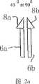
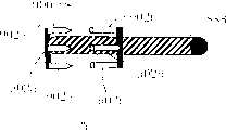
图1a显示了本发明一具体实施方式的光学装置的刨面图。Figure 1a shows a cutaway view of an optical device according to an embodiment of the present invention.
图1b显示了本发明另一具体实施方式的光学装置的刨面图。Fig. 1b shows a cutaway view of an optical device according to another embodiment of the present invention.
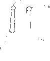
图2a显示了本发明一具体实施方式的光学装置的一部分Figure 2a shows a part of an optical device according to an embodiment of the present invention
图2b显示了本发明另一具体实施方式的光学装置的一部分。Figure 2b shows a part of an optical device according to another embodiment of the present invention.
图2c显示了本发明再一具体实施方式的光学装置的一部分。Figure 2c shows a part of an optical device according to yet another embodiment of the present invention.
图3显示了本发明一具体实施方式的系统的框图。Figure 3 shows a block diagram of a system according to an embodiment of the present invention.
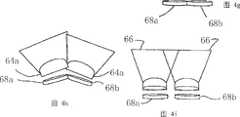
图4a显示了本发明一具体实施方式的光学装置的某些元件的侧视图。Figure 4a shows a side view of certain elements of an optical device according to an embodiment of the present invention.
图4b显示了本发明一具体实施方式的光学装置的刨面图。Figure 4b shows a cutaway view of an optical device according to an embodiment of the present invention.
图4c显示了本发明一具体实施方式的光学装置的俯视图。Figure 4c shows a top view of an optical device according to an embodiment of the present invention.
图4d、4e、4f、4g、4h、4i、4j和4k显示了本发明一具体实施方式的光学装置的一部分的侧视图。Figures 4d, 4e, 4f, 4g, 4h, 4i, 4j and 4k show side views of a portion of an optical device according to an embodiment of the invention.
图5a显示了本发明一具体实施方式的医疗装置的某些元件的侧视图。Figure 5a shows a side view of certain elements of a medical device according to an embodiment of the present invention.
图5b显示了本发明一具体实施方式的医疗装置的某些元件的侧视图。Figure 5b shows a side view of certain elements of a medical device according to an embodiment of the invention.
图5c显示了本发明一具体实施方式的医疗装置的某些元件的示意图。Figure 5c shows a schematic diagram of certain elements of a medical device according to an embodiment of the present invention.
图6显示了本发明一具体实施方式的医疗装置的某些元件的侧视图。Figure 6 shows a side view of certain elements of a medical device according to an embodiment of the present invention.
图7a显示了本发明一具体实施方式的医疗装置的侧视图。Figure 7a shows a side view of a medical device according to an embodiment of the invention.
图7b显示了图7a中医疗装置在不同位置的侧视图。Figure 7b shows a side view of the medical device of Figure 7a in a different position.
图8显示了本发明一具体实施方式的医疗装置的侧视图。Figure 8 shows a side view of a medical device according to an embodiment of the present invention.
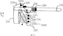
图9显示了本发明一具体实施方式的医疗装置的侧视图。Figure 9 shows a side view of a medical device according to an embodiment of the present invention.
图10a、10b、10c、10d和10e显示了用于本发明某些具体实施方式的医疗装置一部分中的元件的各种不同侧视图。Figures 10a, 10b, 10c, 10d and 10e show various side views of elements used in a portion of a medical device according to certain embodiments of the invention.
图11a、11b、11c和11d显示了用作本发明某些具体实施方式的医疗装置一部分中的元件的侧视图。Figures 11a, 11b, 11c and 11d show side views of elements used as part of a medical device according to certain embodiments of the invention.
图12a、12b、12c显示了用作本发明某些具体实施方式的医疗装置一部分中的工具的侧视图。Figures 12a, 12b, 12c show side views of a tool used as part of a medical device according to certain embodiments of the invention.
图13a显示了本发明一具体实施方式的超声波装置的侧视图。Figure 13a shows a side view of an ultrasound device according to an embodiment of the present invention.
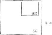
图13b显示了一实施方式中用于图13a中超声波装置的荧屏图像。Figure 13b shows a screen image for the ultrasound device of Figure 13a in one embodiment.
图13c显示了用于本发明一具体实施方式的两个超声波探针。Figure 13c shows two ultrasound probes used in one embodiment of the invention.
图14a显示了本发明一具体实施方式的一种激光器。Figure 14a shows a laser according to an embodiment of the present invention.
图14b显示了一具体实施方式中用于图14a中激光装置的屏幕图像。Figure 14b shows a screen image for the laser device of Figure 14a in one embodiment.
图15a显示了本发明一具体实施方式的医疗装置的侧视图。Figure 15a shows a side view of a medical device according to an embodiment of the invention.
图15b显示了本发明一具体实施方式的另一种医疗装置的侧视图。Figure 15b shows a side view of another medical device according to an embodiment of the present invention.
图16显示了用于本发明某些医疗装置的各种元件。Figure 16 shows various elements used in certain medical devices of the present invention.
图17显示了用于本发明某些具体实施方式的多种不同的烧灼装置。Figure 17 shows a number of different cautery devices used in certain embodiments of the invention.
图18a和18b显示了用于本发明某些具体实施方式的一种装置。Figures 18a and 18b show a device useful in some embodiments of the invention.
图19a、19b和19c显示了用于本发明某些具体实施方式的另一装置。Figures 19a, 19b and 19c show another device useful in certain embodiments of the invention.
图20a和20b显示了本发明某些实施方式中用于钉合组织的布置。Figures 20a and 20b show arrangements for stapling tissue in some embodiments of the invention.
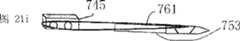
图21a显示了本发明一具体实施方式的一种缝合装置。Figure 21a shows a suturing device according to an embodiment of the present invention.
图21b显示了图21a中缝合装置的一部分。Figure 21b shows a portion of the suturing device of Figure 21a.
图21c和21d显示了本发明一具体实施方式的缝合装置的侧视图。Figures 21c and 21d show side views of a suturing device according to an embodiment of the present invention.
图21e、21f和21g显示了本发明具体实施方式的另一缝合装置的一部分的视图。Figures 21e, 21f and 21g show views of a portion of another suturing device according to an embodiment of the present invention.
图21h显示了本发明一具体实施方式的缝合装置的侧视图。Figure 21h shows a side view of a suturing device according to an embodiment of the present invention.
图21i和21j显示了图21h中缝合装置的一部分的视图。Figures 21i and 21j show views of a portion of the suturing device of Figure 21h.
图21k和21l显示了图21h中缝合装置的一部分的刨面图。Figures 21k and 211 show a plan view of a portion of the suturing device of Figure 21h.
图21m、21n、21o、21p、21q、21r和21s显示了本发明某些具体实施方式的装置的各个不同部分的侧视图。Figures 21m, 21n, 21o, 21p, 21q, 21r and 21s show side views of various parts of devices according to certain embodiments of the invention.
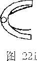
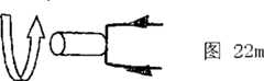
图22a显示了用于本发明某些实施方式的bobbit型缝合固持装置。Figure 22a shows a bobbit-type suture retention device used in some embodiments of the present invention.
图22b显示了一种用于如图21a所示缝合装置的基座,以及一种如图22a所示的bobbit组件。Figure 22b shows a base for the suturing device shown in Figure 21a, and a bobbit assembly as shown in Figure 22a.
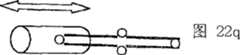
图22c显示了类似于图22a的布置,其具有一种外部bobbit组件。Figure 22c shows an arrangement similar to Figure 22a, with an external bobbit assembly.
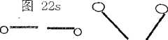
图22d显示了用于本发明某些具体实施方式的一种缝合捕捉器。Figure 22d shows a suture catcher used in some embodiments of the invention.
图22e、22f、22g、22h、22i、22j、22k、22l、22m、22n、22o、22p、22q、22r、22s、22t、22u和22v显示了本发明一具体实施方式的缝合装置的各部分的视图。Figures 22e, 22f, 22g, 22h, 22i, 22j, 22k, 22l, 22m, 22n, 22o, 22p, 22q, 22r, 22s, 22t, 22u and 22v show parts of a suturing device according to an embodiment of the present invention view.
图23a显示了本发明另一具体实施方式的一种铆合器。Fig. 23a shows a riveter according to another embodiment of the present invention.
图23b显示了本发明一具体实施方式的紧固元件。Figure 23b shows a fastening element according to an embodiment of the invention.
图23c显示了如图23b所示紧固元件的另一视图。Figure 23c shows another view of the fastening element shown in Figure 23b.
图23d显示了如图23b所示紧固元件的另一视图。Figure 23d shows another view of the fastening element shown in Figure 23b.
图23e显示了如图23b所示紧固元件的另一视图。Figure 23e shows another view of the fastening element shown in Figure 23b.
图23f显示了一种用于图23b所示的一组紧固元件的盒子。Figure 23f shows a cassette for the set of fastening elements shown in Figure 23b.
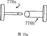
图23g、23h、23i和23j显示了本发明某些具体实施方式中紧固装置的各种不同部分的视图。Figures 23g, 23h, 23i and 23j show views of various parts of a fastening device in certain embodiments of the invention.
图24a显示了用于本发明某些具体实施方式的一种针驱动器。Figure 24a shows a needle driver used in some embodiments of the invention.
图24b显示与图24a类似的针,其中斜槽锁定在打开位置。Figure 24b shows a needle similar to Figure 24a with the chute locked in the open position.
图24c显示与图24a类似的针,但具有一个反向的斜槽。Figure 24c shows a needle similar to Figure 24a but with a reversed bevel.
图24d显示了图24c中的针,斜槽锁定在打开位置。Figure 24d shows the needle of Figure 24c with the chute locked in the open position.
图24e显示了用于本发明某些具体实施方式的各种各样的针。Figure 24e shows a variety of needles used in some embodiments of the invention.
图25a显示了用于本发明某些具体实施方式的各种各样的针。Figure 25a shows a variety of needles useful in certain embodiments of the invention.
图25b、25c、25d、25e、25f和25g显示了用于本发明某些具体实施方式的某些针的刨面图。Figures 25b, 25c, 25d, 25e, 25f and 25g show cutaway views of certain needles used in certain embodiments of the invention.
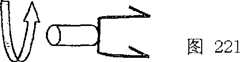
图26显示了本发明某些具体实施方式的一种手枪-型的绑扎装置。Figure 26 shows a pistol-style binding device according to some embodiments of the present invention.
图27a显示了用于本发明一具体实施方式的抓杆的一具体实施方式。Figure 27a shows an embodiment of a grab bar for use with an embodiment of the present invention.
图27b显示了用于本发明一具体实施方式的操纵杆或抓杆的另一具体实施方式。Figure 27b shows another embodiment of a joystick or grab bar for use with an embodiment of the present invention.
图27c显示了用于本发明一具体实施方式的操纵杆或抓杆。Figure 27c shows a joystick or grab bar used in one embodiment of the invention.
图27d显示了用于本发明一具体实施方式的粘合绑扎钉合杆。Figure 27d shows an adhesive binding stapler rod used in an embodiment of the present invention.
图27e显示了本发明一具体实施方式的一种粘合缝钉载入装置。Figure 27e shows an adhesive staple loading device according to an embodiment of the present invention.
图27f显示了本发明一具体实施方式的一种向压缩模具内注射粘合物质的注射器。Figure 27f shows a syringe for injecting adhesive mass into a compression mold according to an embodiment of the present invention.
图27g显示了与图27f所示类似的注射器。Figure 27g shows a similar syringe to that shown in Figure 27f.
图28a显示了用于本发明一具体实施方式的一种紧固元件。Figure 28a shows a fastening element used in one embodiment of the present invention.
图28b显示了图28a中的紧固元件处于关闭位置。Figure 28b shows the fastening element of Figure 28a in the closed position.
图28c显示了与图28a所示类似的紧固元件,其处于不同位置。Figure 28c shows a similar fastening element to that shown in Figure 28a, but in a different position.
图29a显示了用于本发明一实施方式、与图28a所示类似的紧固元件。Figure 29a shows a fastening element similar to that shown in Figure 28a for use in one embodiment of the present invention.
图29b显示了图29a的紧固元件处于关闭位置。Figure 29b shows the fastening element of Figure 29a in a closed position.
图29c显示了图29a的紧固元件处于另一关闭位置。Figure 29c shows the fastening element of Figure 29a in another closed position.
图30a显示了本发明一具体实施方式的一种圆形的钉合器装置。Figure 30a shows a circular stapler device according to an embodiment of the present invention.
图30b显示了图30a中的圆形钉合器装置处于另一种位置。Figure 30b shows the circular stapler device of Figure 30a in another position.
图31a、31b和31c显示了类似于图30a和图30b所示的圆形钉合器的一部分。Figures 31a, 31b and 31c show a portion of a circular stapler similar to that shown in Figures 30a and 30b.
图32a和32b显示了圆形钉合器头的视图。Figures 32a and 32b show views of a circular stapler head.
图33显示了本发明一具体实施方式的圆形钉合器的一部分。Figure 33 shows a portion of a circular stapler according to an embodiment of the present invention.
图34显示了本发明一具体实施方式的圆形钉合器的一部分的侧视图。Figure 34 shows a side view of a portion of a circular stapler according to an embodiment of the present invention.
图35显示了本发明一具体实施方式的手术装置的侧视图。Figure 35 shows a side view of a surgical device according to an embodiment of the present invention.
图36a显示了与图35所示类似的手术装置的侧视图。FIG. 36a shows a side view of a surgical device similar to that shown in FIG. 35 .
图36b显示了图36a中手术装置的一部分的侧视图。Figure 36b shows a side view of a portion of the surgical device of Figure 36a.
图37a显示了本发明一具体实施方式的医疗装置的一部分。Figure 37a shows a portion of a medical device according to an embodiment of the invention.
图37b、37c、37d、37e和37f显示了用于与图37a所示类似的医疗装置的元件的不同具体实施方式的视图。Figures 37b, 37c, 37d, 37e and 37f show views of different embodiments of elements for a medical device similar to that shown in Figure 37a.
图38显示了用于本发明一具体实施方式的医疗装置的一部分的侧视图。Figure 38 shows a side view of a portion of a medical device for use in an embodiment of the invention.
图39显示了本发明另一具体实施方式的医疗装置的侧视图。Figure 39 shows a side view of a medical device according to another embodiment of the present invention.
图40a显示了本发明另一具体实施方式的医疗装置的视图。Figure 40a shows a view of a medical device according to another embodiment of the present invention.
图40b显示了用于类似于图40a中的医疗装置的一部分的视图。Figure 40b shows a view for a portion of a medical device similar to that in Figure 40a.
图40c和40d显示了用于类似于图40b中的医疗装置的一部分的视图。Figures 40c and 4Od show views for a portion of a medical device similar to that in Figure 40b.
图40e显示了用于类似于图40b中的医疗装置的一部分的视图。Figure 4Oe shows a view for a portion of a medical device similar to that in Figure 40b.
图41显示了本发明一具体实施方式的、类似于图40a的装置的视图。Figure 41 shows a view of a device similar to Figure 40a, according to an embodiment of the invention.
图42显示了本发明另一具体实施方式的用于类似于图41中的医疗装置的一种装置的视图。FIG. 42 shows a view of another embodiment of the present invention for use in a device similar to the medical device in FIG. 41 .
具体实施方式Detailed ways
通过以下针对具体实施方式的详细描述,可以进一步理解本发明。这里所使用的术语只是用于解释本发明而不是对本发明的限制。The present invention can be further understood through the following detailed description of specific embodiments. The terms used herein are only used to explain the present invention rather than limit the present invention.
在一具体实施方式中,本发明提供了一种用于微创手术的光学装置,其允许使用者观察复数个(即两个或两个以上)处于各种布置或各种格式的图像。该装置通过多个图像获取装置获得这些图像。每个图像获取装置获得一个图像并将它传送至一个能够显示各种格式图像的显示装置。在一具体实施方式中,该装置允许使用者在双目(binocular)图像显示和三目图像显示(trinocular image presentation)之间切换。In one embodiment, the present invention provides an optical device for minimally invasive surgery that allows a user to observe a plurality (ie, two or more) of images in various arrangements or formats. The device acquires these images through a plurality of image acquisition devices. Each image acquisition device acquires an image and transmits it to a display device capable of displaying images in various formats. In a specific embodiment, the device allows the user to switch between binocular image presentation and trinocular image presentation.
在一具体实施方式中,提供了一种具有两个图像获取装置的光学装置。图1a显示了这样的光学装置2的刨面图。壳体4侧面包围着两个线状图像获取装置6a和6b。壳体4沿着图像获取装置6a和6b线性延伸。壳体4的至少一部分设计成可插入到患者体内。同样地,壳体4的至少一部分便于清洁和杀菌,以便光学装置2可以清洁、杀菌以及重复使用。In a specific embodiment, an optical device with two image acquisition devices is provided. FIG. 1 a shows a cutaway view of such an
线状图像获取装置6a和6b可设计成依照任何适当的方式获取图像。例如,图像获取装置6a和6b可以是光纤电缆或者数字化捕获图像并将其电子化传输的照相机。在后面具体实施方式中,照相机可设置在线状壳体4的一端并通过线路或者其它适合的方式沿着线状壳体4传输电子信号。The linear
图像信息可采用无线发射器传输(电子的或光学的)。电子数据被适当地设置成特定的波长和频率,以保证其安全可靠并避免与其它设备相互干涉,例如附近的医疗设备,如电磁成像设备。也可以采用短程光学“无线”传输,尤其是在那些无线电子传输成问题或可能成问题的地方。Image information can be transmitted using wireless transmitters (electronic or optical). Electronic data is properly set to specific wavelengths and frequencies to keep it safe and secure and avoid interference with other equipment, such as nearby medical equipment, such as electromagnetic imaging equipment. Short-range optical "wireless" transmission can also be employed, especially where wireless electronic transmission is or could be a problem.
图1b显示了光学装置的另一具体实施方式的刨面图,其中,三个图像获取装置6a、6b、以及6c被壳体4保护,壳体4侧面地包围着线状图像获取装置6a、6b和6c。这种具体实施方式允许光学装置收集三个图像向使用者显示。在另一具体实施方式(未显示)中采用一个或一个以上光源为图像获取装置6a、6b和6c提供照明。可选择地,任意一个图像获取装置,如6b,可被一个光源取代,以便为图像获取装置6a和6c提供照明。Figure 1b shows a plan view of another embodiment of the optical device, wherein three
图2a显示了如图1a所示的光学装置的一部分的视图。在图2a所示的这部分光学装置中,提供了两个图像获取装置6a和6b。每个图像获取装置6a和6b被提供一个图像调整装置8a和8b。图像调整装置8a和8b可以是适于处理图像的任何装置,如棱镜、透镜、反射镜、或者上述元件的组合物。Figure 2a shows a view of a part of the optical device as shown in Figure 1a. In the part of the optical arrangement shown in Figure 2a, two image acquisition means 6a and 6b are provided. Each image acquisition means 6a and 6b is provided with an image adjustment means 8a and 8b. The
图2b显示了类似于图2a所示光学装置的一部分的视图。图2b所示的这部分光学装置包括两个图像获取装置6a和6b。图像调整装置8a和8b与图2a中所示的图像调整装置相似,然而在图2b中,图像调整装置8a和8b的定向不同从而为每个图像调整装置8a和8b提供了不同的视野。Figure 2b shows a view of a portion of an optical device similar to that shown in Figure 2a. The part of the optical arrangement shown in Figure 2b comprises two
图2c显示了类似于图2a和2b所示光学装置的一部分的另一视图,然而在图2c中,采用了一个图像调整装置10。这个图像调整装置10可以被定向以便提供两个图像。每个图像被提供到一个单独的图像获取装置(未显示)。Fig. 2c shows another view of a part of an optical arrangement similar to that shown in Figs. 2a and 2b, however in Fig. 2c an
图3显示了本发明的成像系统18的一具体实施方式的系统框图。在这种具体实施方式中,光学装置20包括多个线状图像获取装置22a、22b和22c以及至少一个输入调整装置24。采用一个控制器26接收和响应指令以便控制成像系统18。特别地,控制器26可以与输入调整装置24和显示系统28通讯。控制器26可以控制与图像获取相关的各种特征中的多种,例如,聚焦图像或者旋转设置在图像获取装置上的镜子以便旋转或者改变显示在成像系统18中的视图。另外,或可选择地,控制器26可以操作以控制显示系统28。在这种具体实施方式中,控制器26可以控制与显示装置关联的各种不同特征,例如,色度、颜色、亮度、锐度、对比度、或者任意的各种众所周知的可以在图像获取装置中被调整的其它特征。此外,控制器26可以指令光学装置20获得的图像以哪样的显示格式被显示。例如,使用两个图像获取装置(未显示)时,图像可以被显示成一个图像格式或两个图像分处两旁的左/右图像格式。当采用三个图像获取装置22a-c时,第三个图像可以被作为一个屏幕插图显示。在又一个可供选择方式中多个图像获取装置被采用,来自任何一个或一个以上图像获取装置的图像可以在显示系统28中被选择显示。FIG. 3 shows a system block diagram of an embodiment of the
显示系统28可以是传统的具有一个监视器和一个显示屏的电视类型显示装置、具有镜片型框架并向使用者的每只眼睛呈现独立图像的目镜类型显示装置、或者一个或一个以上上述装置的组合物。在后面的实施方式中,图像可以在两眼之间改变从而左眼接收由其中一个线状图像获取装置提供的左侧图像并且右眼接收由不同的线状图像获取装置获取的右侧图像。可选择地,第三图像可以作为插图显示在左眼图像和/或右眼图像中,或者根据使用者的需要,完整替换左眼图像或者右眼图像。通过控制器26的操作使用者可以任意选择这些选项。当显示系统28包括镜片-框架类型显示装置时,它可以随意地设计从而一只或一双眼睛的显示屏可以向上或向下滑动以便从使用者的一只或一双眼睛的前方完全移开。在一具体实施方式中,采用多个显示装置。
在一具体实施方式中,控制器26通过声控操作以便使用者只需要用听得见的口头命令指挥控制器26执行一些功能或者改变成像系统18的操作。可选择地,或者与声控结合,控制器26可以提供一些部件供使用者手动操作,包括各种控制元件如按钮、开关、转盘、或者任意的可以允许使用者控制成像系统18的一个或一个以上功能的其它控制元件。In one embodiment, the
图4a显示了两个线状图像获取装置6a和6b,在线状图像获取装置6a和6b的末端分别设有输入调整装置36a和36b。每个输入调整装置36a和36b提供了一个机构以便操作由图像获取装置6a或6b获得的图像。输入调整装置36a和36b可以是镜子或者透镜或者一个或一个以上镜子和透镜的组合物,输入调整装置36a和36b用于放大和/或聚焦图像。在一具体实施方式中,采用的透镜能够使图像在0~40倍放大率的范围内放大。这种放大能力可以用于所有的透镜或一个单独的透镜。当使用双目镜光学装置时包括两个图像获取装置6a和6b或者在多个图像获取装置中仅选用两个,放大可以只应用于一个透镜。这个透镜可以提供0和40倍之间的放大调整。这可以被用于提供同一对象或对象集合的多个视图。在另一具体实施方式中,输入调整装置36a和36b可以设计成提供图像的数字放大操作,根据使用者的需要放大或者聚焦。这种数字操作可以结合于,或取代,用于图像放大的一个或一个以上镜子和/或透镜。Fig. 4a shows two linear
图4b显示了采用三个图像获取装置时可以获得的各种视图。在图4b中,右视图区42a被标上R,左视图区42b被标上L,同时后部或背部视图区42c被标上P。透镜44a、44b、或44c分别与每个视图区42a、42b、或42c关联。从图4b可以看出,如何在仅有两个视图区的系统上向使用者提供便利,是通过增加的具有背部视图42c的视野。还可以看出左视图区42b和右视图区42a是如何可以结合起来提供一个完整,或者无缝的视图区。在一具体实施方式中,左视图区42b和右视图区42a结合起来提供一个大约0到180°的区域同时背部视图区42c可以被用于提供一个大约190到350°的视图区。可选择地,各种区42a、42b和42c可以被设计成它们中的一个或一个以上重叠,或者它们中的每一个完全分离。Figure 4b shows the various views that can be obtained using three image acquisition devices. In Figure 4b, the
图4c提供了各个视图42a、42b和42c的另一种表示方法,这可以依照本发明的某些具体实施方式获得。如图4c所示,光学装置(未显示)可设置成各视图42a、42b和42c彼此基本邻接。可选择地,两个或多个视图42a、42b和42c可以重叠,或视图42a、42b和42c可彼此完全分离。Figure 4c provides an alternative representation of the
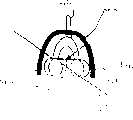
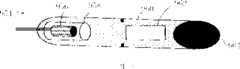
图4d显示了本发明一具体实施方式的光学装置50的侧向内部视图。光学装置50具有至少一套图像传输装置如光缆52,其最好具有柔韧性。光缆52可以随意地采用一个图像捕获机构54,如一台照相机或透镜。一个或一个以上光源56a和56b也可以被用来为检查或者手术区域照明。反射表面,如镜子58a和58b,也可以被用作必要元件或者需要元件。镜子58a和58b可以用来使来自光源56a和56b的光线改变方向或者使图像改变方向而进入图像传输装置如光缆52。透镜60可以被用于进一步修正和调整来自光源56a和56b的一个或两个光线或者被引导到图像传输装置(如光缆52)的图像。此外,保护透镜62可以被用在光学装置50的外面上或者靠近光学装置50的外面。Figure 4d shows a side internal view of an
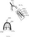
因此,可以理解,采用多个透镜可增加该装置的视野。这些多个透镜可以是或者可以包括球形透镜盖或球形透镜。球形透镜盖64a和球形透镜64b分别在图4e和4f被显示。这些中的每个都可以用作能够放大和/或扩展内部透镜68的视野66的广角光学透镜。特别地,球形透镜盖64a和/或球形透镜64b可用来扩展视野66,如扩展到180°,在远离内部透镜68的一侧有效地将视野66扩展成具有较大宽度的梯形。内部透镜68可以用来放大或者另外调整视野66。Thus, it can be appreciated that the field of view of the device can be increased by employing multiple lenses. The plurality of lenses may be or may include spherical lens caps or spherical lenses.
进一步地,球形透镜盖64a和/或球形透镜64b可以同堆叠的内部透镜68a和68b一起,如图4g、4h和4i所示进行堆叠。如图4h所示,内部透镜68a和68b按一定角度定位并采用了两个球形透镜盖64a。图4i显示了另一种布置,内部透镜68a和68b横向布置,从而使视野66重叠。Further,
图4j和4k显示了类似于图4i所示的球形透镜64b布置,不同之处在于图4j和4k所示的具体实施方式使用了单个内部透镜68a和多个球形透镜64b。本领域的技术人员可以理解,多种布置都是可行的。在图4j中,球形透镜64b的堆叠获得了普通的两个邻接的视野66。图4k显示了球形透镜64b的堆叠导致了两个重叠的视野66。Figures 4j and 4k show a
如需要或必要的话,上述堆叠观念可应用于任何一种光学面。另外,上述球形透镜和透镜盖可进一步设有保护透镜盖,该保护透镜盖如此定形使其不产生任何光学调整或变形。而且,这些保护透镜盖还保护光学装置不受外部环境的损害。The stacking concepts described above can be applied to any type of optical surface if desired or necessary. In addition, the above-mentioned spherical lens and lens cover may be further provided with a protective lens cover shaped so as not to cause any optical adjustment or deformation. Furthermore, these protective lens covers also protect the optics from the external environment.
在本发明的另一种方案中,提供一种允许外科医生在患者体内操作一个或一个以上工具的医疗装置,而且插入患者体内的仅仅比该装置的工具部分稍多一点。图5a显示了这种具体实施方式的医疗装置80。在这种具体实施方式中,提供了一个接受使用者右手或左手的手柄82。在某些具体实施方式中,手柄82被设计成接受一只戴手套的手。手柄82还可以被设计成双面的,以便通用的接受使用者的任意一只手。在某些具体实施方式中,手柄82可以固定尺寸以便接受一只特定的手,如尺码6-8的手作为外科医生的手套的规格。手柄82可以包括用作使用者的手指84a-e的独立部分。一个或一个以上作为使用者的手指84a-e的部分可以随意地组合,因此使用者的手指停放在一个像棒球手套一样的区域里(未显示)。In another aspect of the invention, a medical device is provided that allows a surgeon to manipulate one or more tools within a patient with only slightly more than the tool portion of the device inserted into the patient. Figure 5a shows a
在一具体实施方式中,提供了一个或一个以上压力传感器86a-d。每个压力传感器86a-d探测相应手指施加的压力大小。这个信息被传递到一个与器具部(instrument portion)(未显示)关联的机构(未显示),器具部用于操作一个工具(未显示)。该机构响应由特定手指施加的压力大小并对应地调整工具的操作。这样,当使用者在压力传感器86a-d上施加较大的力量时,工具将执行一个较大的力量。在这种具体实施方式中,工具的一个特征可以被固定。例如,当工具是镊子时,镊子的一个分叉可以被固定,而另一个分叉可以活动。可选择地,或者与这种压力系统相结合,工具和机构可以设计成能够将使用者施加压力的任何反作用力传递给使用者。例如,如果工具是一个镊子,一旦镊子因为完成了组织的挤压或者其它材料的抓取而到达了一个不能再继续合拢的点时,用于操作镊子的控制杆88同样地不能再继续合拢。这样,使用者的体验就像是使用者直接地对被操作的材料工作,而不是通过医疗装置80的各种机械或电子联接。In a particular embodiment, one or
医疗装置包括器具部100(如图5b所示)和一个或一个以上用于允许使用者操纵工具(未显示)的装置或者控制元件。工具与器具部100或者医疗装置80的其它部件关联。在一具体实施方式中,采用板机(未显示)和控制杆88操纵工具。在一种设有板机的具体实施方式中,板机可以通过挤压使用者的一根手指而被操纵并引起工具的一些操作。例如,挤压板机可以引起工具旋转。控制杆88可以通过挤压使用者的一根或多根手指而被操作,进而操纵工具。在可替换的具体实施方式中,控制杆88和板机的操作可以被颠倒或者可以是另外采用按钮或开关或一些其它的控制元件或控制元件的组合。The medical device includes an implement portion 100 (shown in Figure 5b) and one or more devices or control elements for allowing a user to manipulate a tool (not shown). Tools are associated with the instrument portion 100 or other components of the
在图5b中,显示了器具部100。器具部100收容并包括用于操纵和操作工具102的机构。板机(未显示)可以操作以使工具102按照箭头B的方向旋转,从位置I到位置II。在一具体实施方式中,工具102可旋转到几个预先设定的位置之一,如工具102可以相对于器具部100成0度、45度或90度角。当为0度角时,工具102相对于器具部100呈一条直线。在另一具体实施方式中,工具102可以被设定在相对于器具部100成0度角到90度角之间的任何位置。In Fig. 5b, an appliance part 100 is shown. The implement portion 100 houses and includes mechanisms for manipulating and operating the
请参照图5a和5b,可以更全面理解该装置的各种元件的相互作用。一个经皮轴(transcutaneous shaft)104配合一个内部轴(internal shaft)106。内部轴106随意地可拆卸结合于经皮轴104并且沿着经皮轴104直线延伸。内部轴106被结合于工具102。工具102可以随意地从内部轴106上分离。旋钮108被采用并且可以被操作以使内部轴106和任何结合的工具102旋转,例如按照箭头A的方向。可选择地,旋钮108可以被设置在经皮轴104的前端,或者旋钮108的功能可以由手柄82上的其它控制元件提供。Referring to Figures 5a and 5b, the interaction of the various elements of the device can be more fully understood. A transcutaneous shaft 104 engages an
在图5b的具体实施方式中,工具102显示为镊子。依照本发明,工具102可以是各式各样的其它有用装置,尤其是那些在医疗手术中有用的装置。例如,工具102可以是镊子、平剪刀、弯剪刀、直角剪刀、DeBakey-型镊子、直角镊子、钝镊子、弯夹钳(curved clamps)、有角夹钳、超声波探测器、激光器、烧灼装置、钉合器(staplers)、刀、缝合装置、铆合器(rivet driver)、绑扎装置(ligation device)、抽吸装置(aspiration device)、注射装置、活组织检查装置(biopsy device)、放射治疗装置、或放射性发射器载入装置。工具优选的是三种类型之一。第一类工具设计为一次性使用并被随后丢弃。第二类工具是可替换的并且优选的是能够灭菌的。在这种装置中,全部器具可以被清洁和灭菌以便重复使用或者工具本身可以被取下以便于清洁和灭菌。在第三类工具中,多种不同的工具可以交替地被一个装置使用,而且可根据使用者的需要从装置上拆卸并重新安装到装置上。In the particular embodiment of Figure 5b, the
图5c显示了可用于本发明式的某些压力传感器布置示意图。在图5所示的布置中,压力传感器116a-d分别用于拇指和前三根手指。如上所述,操作工具的机构响应特定手指所施加压力的大小并相应地调整工具的操作。操作工具的机构在性质上可以是机械的或电的,或者是两者的结合。Figure 5c shows a schematic diagram of some pressure sensor arrangements that can be used in the present invention. In the arrangement shown in Figure 5, pressure sensors 116a-d are used for the thumb and first three fingers, respectively. As noted above, the mechanism for operating the tool responds to the amount of pressure applied by a particular finger and adjusts the operation of the tool accordingly. The mechanism for operating the tool may be mechanical or electrical in nature, or a combination of both.
依照本发明的某些具体实施方式,压力传感器118a和118b还可以被用于医疗装置的工具上。在一具体实施方式中,工具是一个镊子,其中一个分叉固定而另一个分叉可活动。压力传感器118a和118b可以被用在这种布置中以检测施加在镊子上的压力。压力传感器118a和188b可以被设计成将它们感应的压力传送给使用者,通过机械或者电机构,如前面所述。可选择地,用于传输压力传感器118a和188b产生的压力信号的机构在性质上既是机械的也是电子的。According to certain embodiments of the present invention, pressure sensors 118a and 118b may also be used on tools of medical devices. In a specific embodiment, the implement is a tweezers, one of which is fixed and the other is movable. Pressure sensors 118a and 118b may be used in this arrangement to detect the pressure exerted on the forceps. Pressure sensors 118a and 188b may be designed to communicate the pressure they sense to the user, either through mechanical or electrical mechanisms, as previously described. Optionally, the mechanism for transmitting the pressure signals generated by pressure sensors 118a and 188b is both mechanical and electronic in nature.
请参照图6,显示了医疗装置130的另一具体实施方式。该装置130包括一个烧灼按钮132。烧灼按钮132与工具(未显示)中的一个用于使工具的至少一部分加热以便允许使用者烧灼组织的机构关联。在一具体实施方式,烧灼按钮132的激活闭合了一个电路(未显示)从而电压被转移到工具上,然后工具准备好向组织提供电烙术。一旦烧灼按钮132被撤销工作,电流将不再被转移到工具并且工具开始冷却。医疗装置130通常与电路绝缘从而电荷不会不经意地被传送到医疗装置130的其它部分或使用者。随意地,烧灼按钮132的功能可以由不同的控制元件或部件提供。Please refer to FIG. 6 , which shows another specific embodiment of the
手柄134包括彼此分离的手指部136a-d,手柄134可以被设计以便使用者的手完全地或者部分地与手柄134相配。在这种具体实施方式中,手柄134包括被设计用于接受使用者的手的内部部分(未显示),并且优选地是接受戴手套的手。内部部分可以通过手柄134上具有足够大尺寸的开孔138进入,从而允许使用者的手或其一部分进入手柄134的内部部分。板机140和板机护手142被定位以便于使用者的食指接近。在手柄134的内部空间里还可以采用把手或手掌支撑144。把手或手掌支撑144便于医疗装置130的操纵,而且帮助使用者牢固地抓住装置130,以避免滑移。在该图中还显示了用于内部轴148的旋转旋钮146。The
图7a显示了本发明另一具体实施方式的一种医疗装置160。采用包括第一延长部164a和第二延长部164b的剪刀-型手柄162。共同地,第一延长部164a和第二延长部164b可以相对运动,就如同剪刀的两个手柄的操作。这些延长部164a和164b沿着箭头C的路径运动以操作工具166。烧灼按钮168被提供并且按照类似于前面所述的方式操作。另一个按钮170转动工具166使其相对装置160呈一定角度。按钮170按照与前面针对本发明其它具体实施方式的板机的描述相类似的方式操作。这种具体实施方式显示了可供选择的单轴172,其可相对手柄162旋转,例如沿着箭头D的路径。旋转旋钮174被提供以便使用者旋转轴172。如同其它具体实施方式一样,控制元件不限制于附图所示的布置。Fig. 7a shows a medical device 160 according to another embodiment of the present invention. A scissor-type handle 162 comprising a first extension 164a and a second extension 164b is employed. Collectively, the first extension 164a and the second extension 164b can move relative to each other, just like the two handles of scissors. These extensions 164a and 164b move along the path of arrow C to operate tool 166 . A cautery button 168 is provided and operates in a manner similar to that previously described. Another button 170 turns the tool 166 at an angle relative to the device 160 . Button 170 operates in a manner similar to that previously described for triggers of other embodiments of the present invention. This embodiment shows an alternative single shaft 172 that is rotatable relative to the handle 162 , for example along the path of arrow D . A rotation knob 174 is provided for the user to rotate the shaft 172 . As with other embodiments, the control elements are not limited to the arrangements shown in the figures.
图7b显示了图7a所示医疗装置160的不同位置的侧视图。在图7b中,剪刀-型手柄162处于关闭位置。具体地,第一延长部164a和第二延长部164b被相对运动。Figure 7b shows a side view of a different position of the medical device 160 shown in Figure 7a. In Fig. 7b, the scissor-type handle 162 is in the closed position. Specifically, the first extension 164a and the second extension 164b are relatively moved.
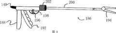
图8显示了本发明另一具体实施方式的手枪型医疗装置186。在这装置186中采用了一个适合与使用者的手掌配合的手枪型手柄188。在其它方面,医疗装置186与前面所述的那些类似。提供了一个烧灼按钮190,还有一个用于操作工具194的控制杆192。还提供了一个板机护手196,还有一个用于使工具194相对装置186旋转的板机198。这种具体实施方式显示了一个单(经皮)轴200以及一个固定于单轴200末端的可拆卸工具194。旋转旋钮202被用于旋转单轴200和固定在单轴上的工具194。FIG. 8 shows a pistol-type
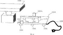
图9显示了具有手掌/手腕束套(circumferential band)216和撬棒(sleds)218a-d的另一种医疗装置214,撬棒218a-d分别用于放置拇指、中指、无名指和小指。束套216用于将医疗装置214绑在使用者的手上以避免滑移。在其它方面,医疗装置214图8中所示的类似。可以采用一个手柄(未显示)让使用者用手抓住就像图8所示的具体实施方式中的手枪型手柄那样。提供了一个烧灼按钮220,还有一个用于操作工具(未显示)的控制杆222。还提供了一个板机护手224,还有一个用于使工具相对装置214旋转的板机226。这种具体实施方式显示了一个单经皮轴228a,旋转旋钮230被用于旋转轴228和固定在轴上的工具。9 shows another
在图9所示的医疗装置214中可采用具有压力传感器232a-d的撬棒218a-d。压力传感器232a-d基本上按照与前面图5a和图5c相同的方式操作,并提供使用者和装置之间的关于工具所遇到的组织密度(如软组织、硬组织或骨头)的感觉输入(sensory input)或者使用者施加在装置214上的压力。撬棒可如此构造,以获得如图5a所示手套型手柄类似的功能。Crowbars 218a-d having
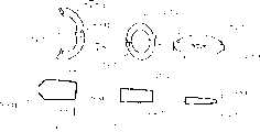
请参照图10a、10b、10c、10d和10e,提供了可以用于本发明的某些具体实施方式的各种剪刀型工具。图10a显示了一把具有第一切割元件245a和第二切割元件245b的平剪刀(flat scissors)工具244。剪刀工具244可以采用多种尺寸,如小号的梅奥(Mayo)型剪刀。剪刀工具244可以被旋转,例如沿着箭头E的方向。这样旋转以后剪刀工具244可以处于图10b所示的位置。图10c显示了一把具有第一切割元件248a和第二切割元件248b的直角剪刀工具246。剪刀工具246可以采用多种尺寸并且功能类似于Potts型剪刀。此外,剪刀工具246可以被旋转,例如沿着箭头F的方向。图10d显示了一把具有第一切割元件252a和第二切割元件252b的弯剪刀工具250。第一切割元件252a和第二切割元件252b均采用弯曲形状。剪刀工具250还可采用各种尺寸并且功能类似于解剖剪刀,如Metzenbaum型剪刀。图10e显示了一把具有第一切割元件256a和第二切割元件256b的烧灼剪刀工具254。另外,切割元件256a和256b分别包括一个加热元件258a和258b。前述任一剪刀工具都可设有加热元件以便烧灼组织。此外,用在本发明各种不同医疗装置上的各种其它工具也可采用加热元件以便烧灼组织。每个剪刀工具244、246、250和254可以旋转。这种旋转可以为在固定着工具的那个轴的轴心线附近的双向旋转,并在轴心线附近与该轴成一定夹角,如同前面关于工具具体实施方式的描述。Referring now to Figures 10a, 10b, 10c, 10d and 10e, there are provided various scissor-type implements that can be used in certain embodiments of the present invention. Figure 10a shows a
请参照图11a、11b和11c,其提供了多种用于本发明某些具体实施方式的镊子工具。图11a显示了一个具有第一抓紧臂272a和第二抓紧臂272b的DeBakey型镊子工具270。镊子工具270可以被设计成适于脉管工作和其它纤细组织的处理。对于精细的工作,镊子工具270可以被设计成仅传递大小受到限制的力量,并且不需要设计成可以传递压碎级别的力量。在一具体实施方式中,镊子工具270具有用于把来自镊子工具270的压力感觉传回使用者的压力传感器274a和274b,如前所述,尤其是参照图5a和5c。图11b显示了图11a中的镊子工具270处于关闭位置。Please refer to Figures 11a, 11b and 11c, which provide a variety of tweezers tools used in some embodiments of the present invention. Figure 11a shows a DeBakey-
图11c显示了一个具有第一抓紧臂278a和第二抓紧臂278b的直角镊子工具276。镊子工具276优选由金属材料或特性近似的材料构成,特别是在材料的密度、强度和柔性方面。镊子工具276的末端可以被设计成各种形状,包括细尖末端、大平钝末端或大钝弯曲或直角末端。Figure 11c shows a right
图11d显示了一个具有第一抓紧臂282a和第二抓紧臂282b的钝镊子工具280。镊子工具280可以被设计成类似于经常在开放性处置中使用的钝末端夹子(clamp),如Babcock型夹子。每个镊子工具270、276和280可以依照前面所述的方式被旋转,在它们被固定到的轴的轴心线两侧并且与该轴心线呈一定角度,如同前面关于工具具体实施方式的描述。Figure 11d shows a
优选地,镊子工具270、276和280可以被设计成模仿普通“开放性”镊子工具的动作,并提供它的感觉和操作。镊子工具270、276和280可具有弹性作用,弹性作用必须被克服才能将镊子工具关闭或者将镊子工具270、276和280的两个抓紧臂相互接近。弹性作用可为使用者提供一种用于确定关闭镊子工具270、276和280所需机械压力的反馈。镊子工具270、276和280可以另外采用如图11a所示的压力传感器作为电的或机械的压力传感器反馈机构的一部分,如前所述。此外,镊子工具270、276和280可以包括一个以压力传感器为基础的反馈机构与纯粹机械反馈机构的结合。纯粹机械反馈机构的一种例子可以是一种结果反馈,结果反馈可以由工具到达它的运动范围界限时的机械联接提供。当控制装置被机械地联接到工具上,控制装置的运动就被限制,如同工具的运动被限制一样。Preferably, the
请参照图12a和12b,提供了可以用于本发明的某些具体实施方式的夹子工具。图12a显示了一个具有第一夹紧臂302a和第二夹紧臂302b的Cooley型夹子工具300。图12b显示了一个具有第一夹紧臂306a和第二夹紧臂306b的Satinski型夹子工具304。夹子工具304的夹紧臂306a和306b分别至少包括一个角度,在一些具体方式中该角度大约为75到85度。每个夹子工具300和304可以依照前面所述的方式旋转,在它们被固定到的轴的轴心线两侧并与该轴心线呈一定角度,如前面关于工具的具体方式所描述。图12c显示了图12b中的夹子工具304旋转到了另一个位置。Referring to Figures 12a and 12b, a clip tool that can be used in some embodiments of the present invention is provided. Figure 12a shows a Cooley-type clamp tool 300 having a first clamping arm 302a and a second clamping arm 302b. Figure 12b shows a Satinski-
尽管夹子工具300和304可以被设计成类似于开放性手术中使用的夹子类型,但是它们特别适合于微创手术。在某些具体实施方式中夹子工具300和304适于折叠成较小的尺寸以便能够穿过套管针端口,或者其它手术切口,然后在患者的体内扩展成展开状态。机械机构或机构的组合可以被用于使夹子工具300和304的两个末端关闭或者接近。机械机构或机构组合传输使用者施加的压力并且优选地适合于向使用者提供关于转移到夹子工具300和304上的阻力大小的反馈。夹子工具300和304可以被设计成可以锁定在一个特定的关闭或接近程度。Although
请参照图13a,提供了一种超声波医疗装置320。超声波医疗装置320用于成像患者的各种组织和构造。装置320能够成像实体、洞穴或者血液或液体填充结构。装置320还能够测量脉管结构的流速并且根据使用者的选择还可以提供组织的图表。例如,使用者可以选举检查肝脏、肺、骨头、肠、脾脏、脉管、卵巢、子宫、或各种其它类型的组织。装置320可以设有比目前可用于超声波装置更小的探针末端322。此外,装置320适于单手操纵从而便于定位和使用。Referring to FIG. 13a, an ultrasonic
超声波医疗装置320可以与光学医疗装置结合使用,或者这里提到的其它微创医疗装置。当与光学医疗装置一起使用时该装置产生的图像可以被结合成一个显示以方便使用者。图13b显示了结合成一个视觉图像330的屏幕图像(如通过照相机获得的图像)以及一个插入超声波图像332。超声波图像332可以完全替换视觉图像330并且超声波图像332可以包括被成像目标的图表描述。例如,超声波图像332可以包括具有检测到的并且与超声波图像332一起显示的脉搏或流速的脉管轮廓线。填充的液体的体积或大小以及其它结构也可以被计算并与超声波图像332一起显示。Ultrasonic
图13c显示了用于本发明的某些具体实施方式的两种超声波探针类型。一种是成像锥形区域336的曲线探针334,锥形区域随着离开探针470的距离越来越远而变得越来越大。第二种是成像圆形区域340的球型探针338,圆形区域一般沿着180度弧、远离球型探针338的方向扩展。第三类适合用于本发明的某些具体实施方式的探针是用于成像脉管结构的平探针(未显示)。在一具体实施方式中,超声波装置可以包括多个可拆分的探针,这样多种超声波探针可以被任意使用。Figure 13c shows two types of ultrasound probes used in certain embodiments of the invention. One is a
图14a显示了本发明另一具体实施方式的激光器350。激光器350可以是任何适当类型的激光器,在一具体方式中为氩激光器。激光器350特别适合用于微创手术中向使用者选择的目标施加激光能量。激光器350包括可活动的末端352,从而可以操纵它。这样,激光器350可被定位以便向第二医疗装置提供的视野传递激光能量。末端352可以被附着到可以有助于方便地操作和引导激光能量的柔性棒354上。激光器350可以是多方向的,以便激光能量可以射向末端352周围的多个离散区域中的其中一个。Figure 14a shows a
图14b揭示了一种显示屏幕364,其显示了用于控制一个如图14a所示的激光器的控制面板。控制面板与一部控制电脑(未显示)关联并且允许使用者选择各种激光强度水平和从激光器末端开始的有效距离。控制面板还为使用者提供了一种选择激光能量相对激光器末端的发射方向的能力。控制面板可以是触摸式的,或者提供单独的键盘和/或指点装置,如鼠标(未显示)以便使用者向控制电脑中输入指令。Figure 14b discloses a
在另一方式中,本发明提供了用于组织烧灼的工具。图15a显示了镊子型烧灼装置380的一具体实施方式的视图。采用一个类似于图7a和7b所示的具有第一延长部382a和第二延长部382b的剪刀型手柄。多种控制元件384a-c,如旋钮、按钮或开关被用于控制工具386。第一控制元件384a可用来触发或解除烧灼。第二控制元件384b可用于定向工具386,如将工具386相对于安装着工具386的轴388旋转一定角度。第三控制元件384c可用于使工具386相对于烧灼装置380缩回或前进。在图15a具体方式中所示的工具386是一个镊子工具386,但也可采用各种其它工具。In another aspect, the present invention provides tools for cauterization of tissue. FIG. 15a shows a view of an embodiment of a forceps-
图15b显示了另一种烧灼装置390。这种烧灼装置390与图15中显示的类似,然而采用了一个棒型手柄(wand-type handle)392。该手柄392使该装置390可以单独地被任意一只手使用。在这种具体实施方式中工具394是一个柱状烧灼工具。还可以采用各种控制元件396a-c。还可以提供一个分离的烧灼控制器398并且通过线缆400连接到烧灼装置390。烧灼控制器398可以包括多种控制器元件402a和402b,控制器允许使用者调整递送到被烧灼组织上的能量强度或者控制烧灼功能的开启或者关闭,或者控制烧灼装置390的一些其它特性。虽然只是参照烧灼装置390进行的描述,但是烧灼控制器398可以被用于各式各样的烧灼装置。Another
图16显示了多种不同类型的烧灼工具末端。这些烧灼工具末端类型包括下列各项:扁平工具412,其为一个钝的方形刀片;镊子工具414,其类似于开放性手术中使用的镊子烧灼工具;球型工具416,其提供一个较大的表面区域以便烧灼更多的组织;圆形工具418,其为钝的并可被用作相对小的工具;以及针形工具420,其用于切断或执行精细解剖。这些烧灼工具被设计成用于探测、碰触和移动组织而不会带来伤害,直到使用者触发烧灼功能。Figure 16 shows a number of different types of cautery tool tips. These cautery tool tip types include the following: flat tool 412, which is a blunt square blade; forceps tool 414, which is similar to forceps cautery tools used in open surgery; ball tool 416, which provides a larger surface area to cauterize more tissue; a round tool 418, which is blunt and can be used as a relatively small tool; and a needle tool 420, which is used to cut or perform fine dissection. These cautery tools are designed to probe, touch and move tissue without causing injury until the user triggers the cauterization function.
图17显示了本发明一具体实施方式的钉合器440。钉合器440被设计用于缝钉组织和/或切割缝钉线(staple lines)之间的组织。钉合器440允许使用者简单地缝钉组织,或者先缝钉然后将缝钉的组织切割。可选择地,使用者可以决定缝钉组织然后采用烧灼剪刀或者烧灼棒分离缝钉线之间的组织。钉合器440提供较好的缝钉线并且形状被特别设计成适合用于微创手术技术。钉合器440包括一个可在冷(环境温度)环境下或者热(如烧灼温度)环境下进行切割的刀(未显示)。钉合器440可设计成单手操作。Fig. 17 shows a
在钉合器440中,提供了一个手柄442,在一具体实施方式中,可以被使用者的右手或左手抓紧。提供了一个具有关闭控制杆444和缝钉控制杆446的两级系统。关闭控制杆444用于操作钉合器在将要被缝钉的组织附近关闭。缝钉控制杆446用于实际操作将组织钉在一起。切割控制元件,例如一个按钮或开关448,执行钉合器440的切割功能,位置控制元件450允许使用者相对钉合器轴454旋转钉合器工具452。钉合器440的缝钉功能和切割功能可以是手动或自动驱动。当缝钉功能是自动时,可以采用气或电或其它适当的方法自动驱动钉合器。In the
在一具体实施方式中,钉合器工具452可以被定位于相对钉合器轴454成0到90度的可调角度。在一种可供选择的具体实施方式中,钉合器工具452可以被定位于相对钉合器轴454成0、45、或90度。In one embodiment, stapler tool 452 may be positioned at an adjustable angle from 0 to 90 degrees relative to
钉合器工具452还可以包括锁扣功能,该功能可确保将要被缝钉或者切割的组织不会在被缝钉前被挤出去。若钉合器被关闭时组织被挤出,复杂性将增加并导致出血或者从缝钉线溢漏。图18a显示了一具体方式,其中锁扣460的运动充分地固持和保证了组织在被缝钉和/或被切割前处于适当的位置。在图18a中,显示了锁扣460处于打开位置。图18b显示了如同图18a一样的具体方式,而锁扣460处于关闭位置。在关闭位置中,锁扣460落在两个砧台462上用于将组织固持在适当的位置。砧台462a和462b被设置成相对呈V形并且砧台462a和462b的末端相对运动以便将组织订在一起。锁扣的使用有效增加了缝钉线的完整性和安全性。The stapler tool 452 may also include a locking feature that ensures that tissue to be stapled or cut is not squeezed out prior to being stapled. If the tissue is squeezed out when the stapler is closed, complications will increase and cause bleeding or spillage from the staple line. Figure 18a shows an embodiment in which the movement of the catch 460 is sufficient to hold and secure the tissue in place prior to being stapled and/or cut. In Figure 18a, the catch 460 is shown in the open position. Figure 18b shows the same embodiment as Figure 18a, with the catch 460 in the closed position. In the closed position, the catch 460 rests on the two anvils 462 for holding the tissue in place. The anvils 462a and 462b are arranged relative to each other in a V shape and the ends of the anvils 462a and 462b move relative to each other to staple the tissue together. The use of the locking buckle effectively increases the integrity and safety of the staple line.
图19a、19b和19c显示了钉合器装置470的一部分的一个可供选择的具体实施方式。在这种具体实施方式中,砧台472a和472b被彼此平行的设置并且整个砧台472a向另一个砧台472b运动或者整个砧台472b向另一个砧台472a运动以便将组织订在一起。图19a显示了钉合器470的砧台472a和472b处于打开位置。锁扣机构474也处于打开位置。图19a、19b和19c所示的锁扣机构的操作类似于图18a和18b的锁扣机构,其中,在砧台472a和472b被关闭而组织被钉住前,锁扣机构避免组织被挤出适当的位置。图19b显示了砧台472a和472b处于打开位置,而锁扣机构474关闭。在图19b显示的位置中,通过锁扣机构474组织被固持在适当的位置,但砧台472a和472b还没有闭合在一起以有效地驱动缝钉穿过组织。图19c显示了钉合器470的一具体实施方式,其中砧台472a和472b处于关闭位置。在图19c中,砧台472a和472b处于几乎彼此直接接触的位置。An alternative embodiment of a portion of a
随意地,钉合器470可以缝钉和切割组织。在一具体实施方式中,通过一个未加热的剃刀片(未显示)执行切割。可选择地,切割可以通过一个加热的剃刀片执行以便在切割的同时烧灼组织。同时对组织进行烧灼和切割防止了切割组织时流血过多。电源可以施加到刀片或者一个单独的烧灼元件(未显示)以便充分地加热组织而进行烧灼。Optionally,
图20a和20b显示了本发明的某些具体实施方式的用于缝钉组织时的布置。两行缝钉线490a和490b被施加到切口492的一侧,而另两行缝钉线494a和494b被施加到切口492的另一侧。切口492把邻近的两条缝钉线490b和494b的边缘分隔开。Figures 20a and 20b show the arrangement of certain embodiments of the present invention when used to staple tissue. Two rows of staple lines 490a and 490b are applied to one side of the incision 492 while two other rows of staple lines 494a and 494b are applied to the other side of the incision 492 . Cut 492 separates the edges of adjacent two staple lines 490b and 494b.
图20b显示了另外的选择,其中组织沿着位于缝钉490a和494a外侧的组织压缩线496a和496b被压缩。通过这种选择,组织在缝钉或切割前被压缩以便减少缝钉或切割前流向该区域的血液。这具有增大缝钉成功率的附加效果用于控制和限制所有脉管(动脉、静脉和毛细血管)中的血液流动。此外,压缩可以有助于保持组织稳定以便于缝钉处置,从而保证缝钉处置能够为某个组织或者为被结合或封闭的多个组织创造一个强有力的并且安全的紧固连接。Figure 20b shows an additional option in which tissue is compressed along tissue compression lines 496a and 496b located outside staples 490a and 494a. With this option, the tissue is compressed prior to stapling or cutting in order to reduce blood flow to the area prior to stapling or cutting. This has the added effect of increasing the success rate of staples for controlling and restricting blood flow in all vessels (arteries, veins and capillaries). In addition, the compression can help to stabilize the tissue for staple disposal, thereby ensuring that the staple disposal can create a strong and secure fastening connection to a tissue or to multiple tissues being bonded or closed.
图21a显示了本发明一具体实施方式的一个缝合装置(suturingdevice)740。采用了一个设有针744的开火枪742,针744适于带动缝合材料穿透组织然后退出来。开火枪742包括一个板机746,每次拉动它,将会使开火枪742推动针744和附着的缝合材料穿透组织然后退出来。可选择地,每次拉动板机746可以仅引起针的部分运动,例如推动针744穿透组织。然后再一次拉动板机746将使针744从组织中退出。轴748可以被用来将开火枪742固定到设有bobbit752的基座750。虽然显示的是内部的bobbit752,但是外部的bobbit(未显示)也可以被采用。Figure 21a shows a suturing device 740 according to an embodiment of the present invention. A firing gun 742 provided with a needle 744 adapted to drive the suture material through tissue and then back out is employed. The firing gun 742 includes a trigger 746, each pull of which will cause the firing gun 742 to push the needle 744 and attached suture material through the tissue and out. Alternatively, each pull of the trigger 746 may cause only partial movement of the needle, eg, pushing the needle 744 through tissue. Pulling the trigger 746 again will then withdraw the needle 744 from the tissue. The shaft 748 may be used to secure the firing gun 742 to the base 750 on which the bobbit 752 is located. Although an internal bobbit 752 is shown, an external bobbit (not shown) could also be used.
图21b显示了图21a所示的缝合装置的其中一部分的操作状态图。在操作中针744在通往bobbit组件752的路径上将缝合材料754钩住然后穿透组织756。针744沿着箭头G的方向运动。针744前进后,停下来。再一次拉动板机,针744撤回。于是在针744的作用下缝合材料754的一部分到达并留在了组织756的另一侧(面对bobbit组件752)。然后针744沿着组织756侧向移动并可以下来穿透组织756以便重新获取缝合材料754的另一部分。Fig. 21b shows an operational state diagram of a portion of the suturing device shown in Fig. 21a. In operation needle 744 hooks
图21c和21d显示了一种针驱动装置500。针驱动装置500被设计用于接受一根直的针和/或一根曲形的针。其包括两个枢转结合的驱动臂502a和502b,例如通过一个铰链。还可以采用一个可伸缩的护板504。铰链506可被分别用于针固持器508a和508b中的一个或一个以上。A
图21e、21f和21g显示了一种止血带(garrot)型针固持器520。图21e显示了空的止血带型针固持器520。提供了一个固持器基座522和一个止血带524。在图21e中,止血带处于松开位置,但在图21f中,止血带524仅仅围绕着针526。图21g显示了止血带型针固持器520的端部视图。止血带在这种具体实施方式中被显示成两个部分,套管弹簧526和套管528。优选地套管528由一般的柔性材料构成,如金属线或尼龙。Figures 21e, 21f and 21g show a
图21m-21s显示了又一种针驱动装置:砧台型针固持器540。在图21m中,显示了砧台型针固持器540的一部分。在这种具体实施方式中,第一夹板542被显示为一个细长的夹板。第二夹板544的中部设有一个枢转铰链546。铰链546允许第二夹板544的一部分相对第一夹板542运动。每个夹板542和544分别设有一个枢转结合的砧台548。图21n显示了一个完整的砧台型针固持器540。显示了图21m中的两个夹板542和544,以及两个用于抓住和操纵装置的环550。砧台开关552被用于每个砧台548,并且被用于分别触发每个砧台548。图21o显示了砧台型针固持器的一部分的侧视图,其中两个夹板分离并且砧台548打开。图21p显示了砧台型针固持器的一部分的侧视图,其中两个夹板分离并且一个砧台548a关闭而另一个砧台548b打开。图21q显示了砧台型针固持器的一部分的侧视图,其中两个夹板关闭并且一个砧台548b关闭而另一个砧台548a打开。图21r显示了具有砧台开关552的砧台型针固持器的一部分的侧视图。图21s显示了一种滑轮和铰链的系统。Figures 21m-21s show yet another needle drive device: an anvil-
适合用于本发明某些具体实施方式的各种尺寸的针包括:6-0、5-0、4-0、3-0、2-0、0-0、1和2。同样地,针744可以是各种合适类型中的任意一种,包括钝的、尖的、标准斜槽的、或反向斜槽的。合适的缝合材料包括dexon、polyglactic910(可从Ethicon公司购买,商品名称为VICRYL)、polydioxanone(可从Ethicon公司购买,商品名称为PDS和PDS II)、尼龙、不锈钢、或单丝材料(可从Ethicon公司购买,商品名称为Proline)。Needles of various sizes suitable for use in certain embodiments of the invention include: 6-0, 5-0, 4-0, 3-0, 2-0, 0-0, 1 and 2. Likewise, needle 744 may be any of a variety of suitable types, including blunt, pointed, standard beveled, or reverse beveled. Suitable suture materials include dexon, polyglactic 910 (available from Ethicon under the trade name VICRYL), polydioxanone (available from Ethicon under the trade names PDS and PDS II), nylon, stainless steel, or monofilament material (available from Ethicon purchased by the company under the trade name Proline).
图21c显示了缝合装置743的另一种布置。在这种大致为枪形的缝合装置743中,bobbit盒子(box cartridge)745可以被设置在或者填装进缝合装置743内。优选地,bobbit盒子被设计成快速地被吸附到适当的位置。各种各样的控制元件被用在缝合装置743上。在特定的布置中,采用一个按钮747操作缝合捕集器(suture catcher)749前进。采用一个操作杆751操作针753前进。板机755被用来触发针753上的斜槽757的关闭或打开。优选地,针753和缝合捕集器杆749从缝合装置743的筒体759中穿出。这种用于bobbit盒子的吸入构造有利于更换缝合材料并且有利于患者体内的缝合装置743重复使用多种缝合材料,例如针对不同的组织。Another arrangement of
图21d和21e显示了bobbit盒子745的布置。在图21d所示的布置中,bobbit缝合线(suture)761是与针753关联工作的双线。图21e所示的布置显示了bobbit缝合线761是与针753关联工作的单线。通常,bobbit可以随意选择而优选地被设计成节省空间并且最小化缠结。Figures 21d and 21e show the
图21f和21g显示了筒体759的刨面图。在图21f中,bobbit盒子745被显示安装在筒体759中。缝合捕集器杆749和针753也在图21f和21g中被显示。其中,图21g所使用的筒体759横截面比图21f所使用的横截面更加远离装置的手柄(未显示)。图21g中显示了一个引导槽763并且提供了一个供缝合材料(未显示)穿过的区域。Figures 21f and 21g show a plan view of the
图22a显示了一种bobbit型缝合固持装置758。缝合固持装置758包括两个用于固持缝合材料754的bobbit 760a和760b。缝合材料754可以在bobbit 760a和760b之间被从左到右的或者从右到左的拉扯。Bobbit 760a和760b被容置着缝合材料(不可见)的中空管762相互连接并且还被外部缝合材料754互相连接,外部缝合材料754可以被针自由捕捉。Figure 22a shows a bobbit type
图22b显示了固定到轴748上的基座750。在该具体方式中,轴748包括一个针引导器764。图22b所示的bobbit 760a和760b可被吸入基座750中的适当位置从而便于在各种不同的缝合材料和缝合尺寸之中转换。FIG. 22b shows the base 750 secured to the shaft 748 . In this embodiment, shaft 748 includes a
图22c显示了与图22a类似的布置,但具有一个外部bobbit组件766。外部bobbit组件766是可选择的而且可以靠近针引导器764的末端设置。Figure 22c shows a similar arrangement to Figure 22a, but with an
图22d-22v显示了用于本发明的某些具体实施方式的缝合捕集器的各种不同具体实施方式。缝合捕集器用于在针前进到最大行程时(也就是在它穿过组织之后,或者正在重新安装)固持(hold)缝合材料。针打开斜槽释放它固持的缝合材料,或它可以打开斜槽接受缝合材料然后关闭以便取走被缝合捕集器固持的缝合材料。在图22e-h和22v所示的具体实施方式中,缝合捕集器被设置在杆上,杆可以是三重铰链连接和弹性安装。前进时,杆形成“C”形以便环绕接触组织,与相对一侧的针相遇。当针被使用者操作前进时,如图22u所示在最大行程它将会旋转接着斜槽被打开(例如通过拉动板机)然后缝合捕集器就能够从针上捕获缝合材料。优选地,针在最大行程的最后0.5到0.2cm的距离穿透捕集器。优选地,捕集器与组织类似,这样针可以容易地穿透并打开缝合捕集器。这避免了可能造成缝合材料撕裂或撕破的任何大的摩擦或者力量。缝合捕集器末端的捕集器可以是“U”形,请参照图22i-k,或者具有倒钩的“U”形,请参照图221-m,或者为封闭环形或“O”形,请参照图22n-22t。在一种封闭环形的具体实施方式中,捕集器材用铰链连接成封闭圈,请参照图22n-22q。优选地,缝合捕集器被设计成当针缩回或者不存在时,捕集器弹性铰链设计将关闭捕集器。当捕集器轴缩回装置的筒体中时,铰链节被拉平从而形成一个平直的轴体。当捕集器前进时,弹性铰链关节可以形成打开的“C”、“U”或“O”型。在操作中,例如,图22n和22p所示的缝合捕集器可以随着针的前进而伸出筒体。随着针斜槽打开和针的撤回,缝合捕集器可以包围缝合材料,而且这样固持着它。Figures 22d-22v show various embodiments of suture traps for use with certain embodiments of the invention. The suture catcher is used to hold suture material while the needle is advanced to its full stroke (ie, after it has passed through tissue, or is being reinstalled). The needle opens the chute to release the suture material it is holding, or it can open the chute to receive the suture material and then close to remove the suture material held by the suture catcher. In the specific embodiment shown in Figures 22e-h and 22v, the suture catcher is provided on a rod, which may be triple hinged and resiliently mounted. When advanced, the rod forms a "C" shape so as to wrap around the contacting tissue and meet the needle on the opposite side. When the needle is advanced by the user, at maximum travel as shown in Figure 22u it will rotate and the chute is opened (eg by pulling the trigger) and the suture catcher can then capture suture material from the needle. Preferably, the needle penetrates the catcher at a distance of the last 0.5 to 0.2 cm of maximum travel. Preferably, the trap is similar to tissue so that a needle can easily penetrate and open the suture trap. This avoids any high friction or force that could cause the suture material to rip or tear. The catch at the end of the suture catcher may be "U" shaped, see Figure 22i-k, or "U" shaped with barbs, see Figure 221-m, or closed loop or "O" shaped, Please refer to Figures 22n-22t. In a specific embodiment of a closed loop, the trapping devices are hinged to form a closed loop, please refer to Figures 22n-22q. Preferably, the suture catcher is designed such that when the needle is retracted or absent, the catcher elastic hinge design will close the catcher. When the catcher shaft is retracted into the barrel of the device, the knuckles are flattened to form a straight shaft. The elastic hinge joint can form an open "C", "U" or "O" shape when the catcher is advanced. In operation, for example, the suture catcher shown in Figures 22n and 22p may extend out of the barrel as the needle is advanced. As the needle chute opens and the needle is withdrawn, the suture catcher can surround the suture material and thus hold it.
请详细参照显示了缝合捕集器具体方式的各个附图,图22e显示了缝合捕集器767,其中针753已前进。图22f显示了图22e所示的具体方式,其中缝合捕集器767已前进。图22g显示了处于关闭位置的一种相似的具体方式,其中缝合捕集器767和针753均收在筒体759内。图22h显示了一种相似的具体方式,其中针753前进并向缝合捕集器767释放缝合材料。图22i-k显示了缝合捕集器767的一具体方式的各种不同位置,从打开位置(如图22i),到部分打开位置(如图22j),再到关闭位置(如图22k)。图22n和22o分别显示了一种三角形缝合捕集器处于打开和关闭位置。图22p和22q分别显示了一种四边形缝合捕集器处于打开和关闭位置。图22r和22t分别显示了一种平“洞”缝合捕集器处于关闭和打开位置,而图22s显示了平“洞”捕集器的侧视图。图22u显示了针753的旋转运动,这可用于从打开的斜槽中释放缝合材料,以及重装缝合材料并关闭斜槽。最后,图22v显示了用于缝合捕集器的一种铰链的放大图,还显示了捕集器轴763和多个弹性体765。Referring in detail to the various drawings showing the specifics of the suture catcher, Figure 22e shows the
图23a显示了另一具体方式的铆合器768。铆合器768被设计成推动和挤压紧固件使其穿过组织。铆合器768可用于紧固或闭合密度大的组织如筋膜、或者食管疝修补中的隔膜蒂状物。铆合器768可包括一个旋转旋钮769a和两个控制杆769b和769c以便让使用者控制铆合器768的部署和操作。铆合器768还包括附着到延长轴772上的手柄770。控制杆769b可以控制,如可控制延长部774a和774b的闭合,其可补充铆钉工具。Figure 23a shows another embodiment of the
每个延长部774a和774b可以包括一个或一个以上爪或倒钩776a-d。倒钩776a-d用于帮助将组织聚拢在一起或者帮助将组织保持在合适的位置或者钉穿组织。倒钩776a-d可以设有锋利的细齿(未显示)。在一具体实施方式中,倒钩776a-d非常短,其便于方便地从组织中退出并且避免伤害被倒钩776a-d抓住的组织。Each
在一具体实施方式中,铆合器768推动紧固件,紧固件由两个铆钉部分778a和778b共同组成因此一旦铆钉部分778a和778b被铆合器768发出它们就不会分开。铆钉部分778a或778b装配在每个延长部774a和774b中。在某些具体实施方式(未显示)多个铆钉部分(未显示)可以被存储在通道或者盒子组件中,当发出一个铆钉部分时,盒子组件自动地装载一个新的铆钉部分。可选择地,采用钉子代替铆钉部分778a和778b。一个卷缩机按钮或控制杆771可以被用于让使用者通过卷缩机(crimper)783分别控制铆钉的压缩,这在后面进行介绍。In one embodiment, the
图23b显示了可以由非吸收性材料构成的铆钉部分778a和778b,包括不锈钢、尼龙、或塑料,或者吸收性材料如polyglactic910(可以从Ethicon公司购买,其商品名称为VICRYL)、polydioxanone(可以从Ethicon公司购买,其商品名称为PDS和PDS II)、含铬材料、聚合材料如聚乙烯、或任何其它的适合材料。每个铆钉部分778a和778b被设计成可以配对,并可与它的配对铆钉部分778a或778b连结。左边的铆钉部分778a包括一个狭窄部分和一个用于穿透组织的末端780。末端780可以是钝的、或球茎状的、或锋利的。还可以采用扁平的、圆盘形端头782a以便于将铆钉部分778a锚定在将要被该铆钉部分778a穿透的组织中。Figure 23b shows
相配的铆钉部分778b具有一个相似的直径,但稍微大些,以便容纳配对铆钉部分778a。相配铆钉部分778b的一端是敞开的以便提供一个通往空心管784a的路径。空心管784a包括内部缺口、凹槽或者扣环(ring)784b,一旦铆钉部分778a和778b被压在一起,内部缺口、凹槽或者扣环784b可以与铆钉部分778a的末端780配合。一旦铆钉部分778a和778b被压在一起,缺口784b可以帮助防止它们脱开。铆钉部分778b的一端也可以采用扁平的、圆盘形端头782b。The
图23c显示了一对铆钉部分778a和778b已经被部分地压在了一起。在图23c所示的构造中,铆钉部分778a和778b配合在一起,而且从这个位置其可被进一步更完全地压合在一起,以便形成稳固地紧固连接。当铆钉部分778a和778b的端头782a和782b被作为锚部用在被铆钉部分778a和778b穿透的组织中时,在附图中可见到端头782a和782b的位置。Figure 23c shows a pair of
图23d显示了铆钉部分778a和778b处于闭合位置。另外,一个卷缩机783被用于铆钉部分778a和778b。卷缩机783压缩由铆钉部分778a和778b形成的紧固件的中央部分,在铆钉部分778a和778b的两个端头782a和782b之间。卷缩机783帮助保证铆钉部分778a和778b坚固地结合成一个稳固的紧固件。Figure 23d shows
图23e显示了在采用了卷缩机783将铆钉部分778a和778b紧固在一起后,铆钉部分778a和778b处于闭合位置。在这种具体实施方式中,可以清晰地看到铆钉部分778a和778b被卷缩机783压缩的情况。Figure 23e shows the
图23f显示了一个可以被装入如图23a所示的铆合器768中的铆钉固持器或者盒子786。铆钉固持器786可以包括一个具有铆钉区的通道788,铆钉在这里被应用。通道788固持着铆钉部分787a-d直到它们将要被使用的时候。通道786还可以包括当需要使用铆钉部分787a-d时用于释放它们的开口790,每次一个。铆钉固持器786可以设计成固持多个铆钉。在一具体实施方式中,铆钉固持器786设计成固持10个铆钉部分787a-d。Figure 23f shows a rivet holder or
图23g显示了两个铆钉部分778a和778b,它们与前面所述的那些相似,然而在这种具体实施方式中,当闭合时,如图23h所示,在接收铆钉部分778b中内部紧固件铆钉部分778a被劈开一个角度(优选地大约九十度)。由将紧固件压合在一起的装置的机构压力所形成的裂口,是不可逆的,其采用从小到中的牵引力。从而,铆钉部分778a和778b被这样固持在一起。图23i显示了各种各样的劈开铆钉部分778a的方法,例如对半平分、三等分或四等分。在另一个可供选择的方式中,铆钉部分778a可以是单独一个,没有配对铆钉部分778b,如图23j所示。在这种具体实施方式中,铆钉部分778a的一部分被劈开用于固定组织。Figure 23g shows two
下面的表格1显示了可以用于本发明的某些具体实施方式的适合的铆钉尺寸。这些尺寸针对组装的和压缩的铆钉。Table 1 below shows suitable rivet sizes that may be used in certain embodiments of the invention. These dimensions are for assembled and compression rivets.
表1
另外,铆钉部分778a和778b可以采用下面的尺寸:轴长0.5cm,闭合后的总长为0.7cm。铆钉端头的直径可以是0.4-0.8cm,厚度可以是0.1cm。末端端头的直径可以是0.3-0.5cm,中空管的直径为0.1cm,并且内部扣环的内直径为0.08cm外直径为0.1cm。Alternatively, the
图24a显示了设有手柄794和延长轴796的针驱动器792,针798安装在延长轴796上。多个控制元件800a-d被用于控制针驱动器792的操作。还可以提供一个斜槽锁扣(bevel lock)802用于关闭针798上的斜槽804。斜槽锁扣802可以被控制元件800a-d中的一个或一个以上控制,例如控制杆800a和按钮800b可以被用来在斜槽804上方打开或者关闭斜槽锁扣802。控制杆800c和800d可以用来使针798前进。Figure 24a shows a
图24b显示了图24a中的针798,其中,斜槽锁扣802处于打开位置。Figure 24b shows the
图24c显示了类似于图24a的针806,但图24c的针806具有一个反向的斜槽808。在图24c中,斜槽锁扣802处于关闭位置。FIG. 24c shows a
图24d显示了图24c中的针806,其中,斜槽锁扣802处于打开位置。Figure 24d shows the
图24e显示了可以用于本发明的某些具体实施方式中的各种各样的针810a-h,特别是图24a中的针驱动器和图21a中的缝合装置。针810a-810d全部包括一个钝的末端,针810e-h全部包括一个尖锐的末端,其可以是圆滑的或者切削的末端。针810a-810h还在斜槽(bevel)类型812上作了改变。针缝810a和810e具有一个传统的开放斜槽812。这允许缝合材料(未显示)滑进或滑出针的抓取(grasp)。针810b和810f具有一个反向的斜槽812。这种布置近似于开放类型,但斜槽812的边缘被向内翻转,使针810b和810f具有了缝合材料的不同的抓取。针810c和810g具有一个推进型斜槽812。在这种布置中,当针810c和810g穿透组织时缝合材料充分被固持在适当的位置,当针810c和810g退出组织时缝合材料被留下。针810d和810h具有拉动型斜槽812。这些针810d和810h与针810c和810g相似,但是他们工作在相反的方向。因此,针810d和810h在它们从组织中退出的时候拉着缝合材料穿过组织,当它们进入和穿透组织的时候将缝合材料留下。优选地,针由不锈钢制成,然而它们还可以由其它的适当材料制成。Figure 24e shows a variety of
当针被用于图21a中的缝合装置时,推进型和拉动型针特别有用。当缝合装置采用内部bobbit时,拉动型针810d和810h是有用的。当缝合装置采用外部bobbit时,推进型针810c和810g是有用的。Push and pull needles are particularly useful when the needles are used in the suturing device of Figure 21a. Pull-
在某些具体实施方式中,针810a-810h采用下列的尺寸:针的规格为6、8、10、12、14、16、18、19、20、22、24、28、30、32;斜槽长度从0.25到1cm;整个针的长度为2cm到15cm,其中,针的一部分设在装置内部,其长度为1cm到10cm,针的另一部分设在装置外部,其长度为1cm到5cm。其它尺寸的针也可以用在本发明中。In certain embodiments, the
图25a显示了用于本发明的某些具体实施方式的针816a-h。这些针816a-h包括用于斜槽的锁扣部件。针816a包括中空管状的鞘820,其沿着针816a横向地滑动以便盖住并封闭斜槽818。在一具体实施方式中,鞘不盖住针816a的末端822。鞘820还可以沿着针滑动到一个打开位置,如针816b所示。针816c还可以采用一个推进器或托杆824。在这种具体实施方式中,各种各样的针可交换使用并且可以根据使用者的需要被安装到推进器824上。可选择地,针和推进器824可以被熔合在一起。Figure 25a shows needles 816a-h used in certain embodiments of the invention. These needles 816a-h include locking features for the chute. Needle 816a includes a hollow
针816e还可以采用一个包括金属线(wire)826的斜槽锁扣机构。金属线826可以在斜槽818上方从打开位置滑动到关闭位置。如关于针816e的附图所示,金属线用于部分地关闭通往斜槽818路径,根据具体情况,从而阻止任何的缝合材料进入或者离开斜槽818。金属线引导通道827可以被提供,而且金属线826至少可以部分地滞留在里面。
针816f可以选择采用一种基于滑动板828的斜槽锁扣机构。附图所示的针816f中,滑动板828a处于关闭位置。附图所示的针816g中,滑动板828a处于打开位置,远离斜槽818。针816h是以侧视图被显示,其中滑动板828a位于斜槽818上方并处于关闭位置。Needle 816f may optionally employ a sliding
图25b和25c显示了采用金属线型斜槽锁扣的针816d的刨面图。在图25b中,截面取自斜槽上方。金属线引导通道827被显示,其可以被用于为金属线826提供引导空间。图25c显示了类似于图25b所示的刨面图,但在图25c中,金属线826部分处于金属线引导通道827的轮廓上方。Figures 25b and 25c show planar views of
图25d和25e显示了采用滑动板型斜槽锁扣的针816f的刨面图。图中可以看出,不同类型的滑动板829a和829b可以被用来锁扣针816f上的斜槽。这些针优选地采用一个通道,滑动板829a和829b可以在通道内滑动。图25d和25e显示了该通道设在滑动板829a或829b与针816f的交集区域。Figures 25d and 25e show planar views of pin 816f using a sliding plate type bevel lock. It can be seen that different types of sliding plates 829a and 829b can be used to lock the chute on pin 816f. The needles preferably employ a channel within which slide plates 829a and 829b can slide. Figures 25d and 25e show that the channel is provided at the intersection of the slide plate 829a or 829b and the needle 816f.
图25f和25g显示了针831的斜槽部分的刨面图。在图25f和25g中,截面取自斜槽处,而且针831的剩下的凸起部分没有显示,因此该视图只是针831的斜槽部分的刨面图。斜槽部分可以是多种尺寸,对于特定的应用方式是有用的。举例来说,图25f所示的斜槽部分,其中针831的大约50%被切掉,图25g所示的斜槽部分,其中针831的大约20%被切掉。Figures 25f and 25g show planar views of the beveled portion of the
因此,可以看出,针可以相对于装置固定,而针的斜槽通过一个活动锁扣(如前面所述的鞘、板或金属线)被打开或者关闭。可选择地,针可以是移动的而针的斜槽锁扣机构(如前面所述的鞘、板或金属线)可以相对于装置处于一个固定位置。针的斜槽可以被设计以便它能够固持缝合材料或者清空或者释放缝合材料。Thus, it can be seen that the needle can be fixed relative to the device while the needle chute is opened or closed by a movable catch such as a sheath, plate or wire as previously described. Alternatively, the needle may be mobile and the needle chute locking mechanism (such as a sheath, plate or wire as previously described) may be in a fixed position relative to the device. The chute of the needle can be designed so that it can hold suture material or empty or release suture material.
图26显示了一种手枪型的绑扎装置828。装置828包括一个与延伸轴832关联的手柄830。某些控制元件834a-f被提供以便于使用者控制装置828的操作。在一具体实施方式中,装置828至少具有四个显著特征之一。第一,装置828可以抓住两个将要被结合的缝合材料,就像开放式器械通常做的那样。第二,使用者可以定位装置828并选择所需的缝合材料的扎紧程度以及缝合材料绑扎的实际位置。第三,结(knot)的等价物可以由缝合材料的熔结(fusion)形成,通过加热或者通过粘合剂熔化。最后,装置828可以提供切断结或者粘合剂熔结上面的缝合材料的选择。可选择地,切断可以由一个单独的剪刀装置(未显示)执行。Figure 26 shows a pistol-
图26显示了本发明的某些具体实施方式优选采用的两种类型的粘合剂绑扎装置中的其中一种。第一种类型包括将液态粘合剂喷射到一个绷带成型模具上(未显示),绷带成型模具可能是热敏感的。通过加热,液态的粘合剂硬化成固定不变的或者半-固定不变的绷带,这由所使用的材料决定。粘着可以由各种适合的粘合剂来完成,包括多种药剂的混合物。可选择地,可以制备各种活性药剂的混合物,它将进行化学反应,在有或者没有热量提供的情况下,产生一个固定不变的或者半-固定不变的固体从而将那里的缝合材料束缚在一起。绷带还可以采用一种当与第三类物质接触时将会变硬的粘合剂形成,其中,第三类物质作为催化剂。在一具体实施方式中,当粘合剂与模具框架接触时将会变硬。合适的粘合剂包括塑料、聚合硅(可从Dow Chemicals获得,商品名称为SILASTIC)、聚丙烯、聚乙二醇、聚乙烯醇、GORTEX、纤维素、三价铬材料、聚乙烯、陶瓷、玻璃和不锈钢。在另一具体实施方式中,缝合材料采用钉合器进行绑缚。Figure 26 shows one of two types of adhesive binding devices that are preferred for use with certain embodiments of the present invention. The first type involves spraying liquid adhesive onto a bandage forming die (not shown), which may be heat sensitive. By heating, the liquid adhesive hardens into a fixed or semi-fixed bandage, depending on the material used. Adhesion can be accomplished by a variety of suitable adhesives, including mixtures of agents. Alternatively, a mixture of active agents can be prepared which will undergo a chemical reaction, with or without the application of heat, to produce an immobilized or semi-immobilized solid to bind the suture material therein together. The bandage can also be formed using an adhesive that hardens when in contact with a third type of substance, wherein the third type of substance acts as a catalyst. In one embodiment, the adhesive will harden when in contact with the mold frame. Suitable binders include plastics, polymeric silicon (available from Dow Chemicals under the trade name SILASTIC), polypropylene, polyethylene glycol, polyvinyl alcohol, GORTEX, cellulose, trivalent chromium materials, polyethylene, ceramics, Glass and stainless steel. In another specific embodiment, the suture material is bound using a stapler.
控制元件834d是一个板机,其触发一个剪刀或者刀片在熔接位置上方切断缝合材料。在一具体实施方式中,缝合材料是在熔接位置上方的0.05cm-1cm被切断。优选地,控制元件834d使刀片或者微型剪刀或常规剪刀前进到一个正好位于缝合材料上方的位置以便过多的材料可以被切掉。优选地,拉动一次板机使刀片或剪刀前进并且随后自动地退回。
绑扎装置828还可以包括一个或一个以上用于操纵缝合材料的杆836。例如,杆836可以被用于推动或者抓住或者拉动缝合材料以便它们可以被绑扎在一起。这些杆836使得绑扎装置828能够被用于稳固地抓住使用者想要绑扎、打结、或熔接在一起的缝合材料。杆836可以与延伸轴832配合。在一具体实施方式中(未显示)绑扎装置828采用了三个杆836。一个杆是用于抓住两个缝合材料,另一个杆是用于熔化或者粘结绑扎材料,第三个杆可以被用于在绑扎后切断缝合材料。可选择地,可以采用前面所述杆中的少数杆的结合。The
图27a显示了用于一具体实施方式的抓杆838的一个具体实施方式。抓杆838包括两个延长的抓住元件840a和840b,它们中的每一个都被设计成在缝合材料或者其它材料附近关闭并且抓住它以便于使用者操纵。在这种具体实施方式中,粘合剂物质填充到如图26所示的绑扎装置828中。粘合剂物质可以具有特别的形状或结构,例如为订书钉的结构。粘合剂物质被应用或者压缩在需要被绑缚的缝合材料上并且粘合剂物质与缝合材料熔接在一起。粘合剂物质可以通过熔接开关的触发而被熔化。熔接开关触发温度控制器,其把加热元件加热以便引起温度敏感粘合剂的熔化。Figure 27a shows one embodiment of a
图27b显示了用于一具体实施方式的钉合器842。钉合器842可以用于将两个缝合材料缝钉到一起而取代利用结把它们系在一起。钉合器包括延长的抓住元件844a和844b,与图27a中所示的类似。每个延长的抓住元件844a和844b还具有一个可以用于促使缝合材料熔接在一起的加热元件846a和846b。在一具体实施方式中,加热元件846a和846b接触在一起闭合了一个电路,从而加热元件被开启。这可以接下来熔化缝合材料或者开始与一些其它粘合化合物(binding compound)(在后面进行描述)热敏反应。优选地,这种加热只需要采用几秒,之后加热元件846a和846b可以被放开。可选择地,加热元件846a和846b可以被粘合化合物代替。粘合化合物可以具有任何适当的形式。在一种布置中,粘合化合物是被压在要被结合的缝合材料上的非金属材料,而且非金属材料黏附在缝合材料上,制造一个粘合物,它的功能等同于将缝合材料系在一起的结。粘合物可以由聚集在一起的不同粘合化合物之间的化学的反应形成,或者它可以是自发的,像以氰基丙烯酸盐粘合剂为基础的胶水,或者热敏材料如铬的材料、塑料、尼龙。材料可以是或不是可吸收性的。因此,抓杆842可以用来抓取将要被紧固在一起的缝合材料然后采用加热元件或者粘合化合物通过化学熔合反应将它们固定。Figure 27b shows a
图27c显示了用于本发明一具体实施方式的一种操纵杆848。杆848被设计用于将缝合材料一起抓住,然后应用可注射的粘合剂将缝合材料粘合在一起。多种适当的结构可以被用于向缝合材料上应用粘合剂。在图27c所示的具体实施方式中,粘合剂850被装在可注射模具852里。在使用中,模具852被杆套854的横向运动压缩,或可选择地,杆848在杆套854里运动并压缩模具852,迫使粘合剂850从粘合剂壳体的两个端口856a和856b流出从而粘合剂850被应用于缝合材料。可选择地,模具852可以被打开以便抓住将要被束缚在一起的缝合材料。在需要的位置,粘合剂被注射,并且缝合材料变成被束缚的。优选地,胶水或粘合剂几乎马上粘结以便在胶水或粘合剂被应用到早已准备好的缝合材料时,它们可以从装置的抓住状态中释放并且被束缚在一起。此外,容器853可以被用于为钉合器容纳和分配胶水或粘合剂。容器853可以被替换并且为管状并且优选地通过向其外表面施加压力的方式分配胶水或粘合剂。Figure 27c shows a
图27d显示了与图27c所示类似的粘合绑扎缝钉杆860,但没有注射元件。这个缝钉杆860可以被用于将缝合材料和粘合剂缝钉固定在一起。在使用中,缝钉杆860可以被推进到一个打开位置然后包住将要被固定在一起的缝合材料。接着应用粘合剂从而缝合材料被固定在一起。Figure 27d shows an adhesive ligating staple shaft 860 similar to that shown in Figure 27c, but without the injection element. This staple bar 860 can be used to hold suture material and adhesive staples together. In use, staple bar 860 can be advanced to an open position and then encases the suture material to be secured together. Adhesive is then applied so that the suture material is secured together.
图27e显示了一种粘合缝钉载入装置862。粘合剂缝钉载入装置862被设计成接受不同类型的多个缝钉864a-864d。在一具体实施方式中,采用了两种类型,热的或冷的缝钉。冷缝钉被绕着缝合材料挤压并紧固在一起,而且不需要热能来固定绑扎物。温度高的或热的缝钉被绕着缝合材料挤压并且应用热能以便实现化学反应从而在将要被紧固在一起的两个缝合材料之间固定出一个粘合物。优选地,缝钉是非金属的,例如,他们可以选自尼龙、聚丙烯、聚乙烯或其它塑料或者其它可以被用于在有压力和/或热量的情况下将缝合材料固定在一起的合适材料。An adhesive
图27f显示了一种向压缩模具868内注射粘合剂物质的注射器866。压缩模具868可以是球形、或矩形、或盒状。缝合材料护板870被用于在压缩模具868内部的粘合剂压缩室872中捕获缝合材料。一旦缝合材料874在压缩模具868内被捕获,压缩模具的两侧868a和868b被相互靠近,或靠紧,而且粘合剂被注射。这样,缝合材料被粘在或束缚在一起。Figure 27f shows a
图27g显示了与图27f所示类似的注射器866。图27g中的注射器866包括一个压缩模具868。但是,该压缩模具868包括矩形的或盒子状的压缩部件876a和876b。压缩部件876a和876b可以采用各种形状或结构中的任意一种。例如,图27f所示的圆球或椭圆或者图27g所示的矩形。图27f所示的球状的粘合剂分配装置使粘合剂大致为球状。图27g所示的管状的粘合剂分配装置使粘合剂大致为管状。Figure 27g shows a
图28a显示了一种可以用来固定或粘合缝合材料的打结钩(tie clasp)878。打结钩878由两个枢转结合的半圆形元件878a和878b构成,以便围绕轴880旋转。Figure 28a has shown a kind of knot hook (tie clasp) 878 that can be used to fix or glue suture material.
图28b显示了图28a中的打结钩878处于关闭位置。在图28b所示的位置,半圆形元件878a和878b闭合成完整的圆、椭圆、或卵形部件。Figure 28b shows the
图28c显示了图28a中的打结钩878的另一视图。在图28c中,打结钩878紧紧关闭。如图示,半圆形元件878a和878b闭合以便紧紧地粘合可能处于半圆形元件878a和878b形成的闭合形状内部的任何缝合材料。Figure 28c shows another view of the
图29a显示了与图28a所示类似的夹子(clip)880。但是,图29a中的夹子880更类似于一个缝钉而不是一个包括两个绕轴枢转的延长半圆形元件的装置。图29a中的夹子880可由金属线、扁平金属或其它适当材料882制成。这段材料882可被弯曲成大致为一端有开口884的“U”形。Figure 29a shows a
图29b显示了图29a中的夹子880处于关闭位置。一段材料882被压在一起以便将开口884(图29a所示)关闭。优选地,一段材料882在一个或一个以上缝合材料附近被关闭以便将他们粘合在一起。Figure 29b shows the
图29c显示了图29a中的夹子880处于另一种关闭位置。在图29c中,夹子880被紧紧地关闭以便一段材料882可以形成一个内部区域比图29b所示更小的环。这可以被用于紧紧地粘合一个或一个以上缝合材料。Figure 29c shows the
请参照图28a-28c和29a-29c,显示了可以被用于本发明某些具体实施方式的某些钩878和880。这些钩878和880被设计成具有一个可以接收将要被粘合的一个或一个以上缝合材料的开口。然后钩878和880在缝合材料附近被关闭以便将它们粘合在一起。根据使用者的意愿和组织的反应,钩878和880可以被闭合在松的或者紧的位置。可选择地,钩878和880可以用于粘合多个组织或者关闭组织中的开口,如关闭一个恶化的肠、脉管、或者其它管状组织、或者具有开口的组织。Referring to Figures 28a-28c and 29a-29c,
图30a显示了本发明一具体实施方式的圆形钉合器装置884。圆形钉合器装置884被用于将内脏片(胃、结肠、肠、食道或其它管状组织)缝钉在一起。圆形钉合器装置884被用于吻合、或内结合多个组织,如管状脉管。圆形钉合器装置884可被设计为具有最小化的大约1cm到大约3cm的特别的内接直径。圆形钉合器装置884被设计成在闭合进行缝钉之前,在必须进入腹腔镜检查端口或者肠内的时候可以被折叠成较小的直径。圆形钉合器884包括一个被附着到延长部分888并且被手柄结构890操作的砧台886。手柄结构890与本发明的其它具体实施方式采用的那些类似(如前面所述)。钉合器头890被设计成根据使用者的需要可以被相对于延长轴888弯折一个角度。弯折圆形钉合器头890充分改善了在狭窄空间内的定位,就像在微创手术过程通常会遇到情况那样。Figure 30a shows a
图30b显示了图30a中的圆形钉合器装置884。但是,延长轴888处于弯折位置。如前面所述,当被弯折时,延伸轴888可以便于钉合器头890更好的定位。从图30b中还可以看到砧台886被定位在比图30a所示的更加接近延伸轴888的位置。Figure 30b shows the
图31a显示了一种用于如图30a所示的圆形钉合器装置的砧台887a。图31a中的砧台887a被铰链连接以便它可以被折叠成较小的尺寸。砧台887a在折叠形态就像砧台887b。图31b显示了由杆891连接的一个砧台886和一个基座889。图31c显示了一个四等分的“饼”结构的砧台893a,其允许尺寸减小(砧台893b)。图31a-31c所示的砧台揭示了构造一种有助于暂时减小其外形或尺寸的砧台的方法以便其可以经由一个入口穿过皮肤或筋膜从而实现胃组织、小肠或结肠的小的切口手术。Figure 31a shows an
请参照图32a和32b,显示了圆形缝钉头890以及延伸轴888。在图32a中所示的圆形缝钉头890本质上是延伸轴888的直线延伸部分从而圆形缝钉头890和延伸轴888成一条直线。在图32b中所示的圆形缝钉头890相对延伸轴888成大约45°的角。如前面所讨论的,圆形缝钉头890的这种根据使用者的意愿从直线位置到弯折位置的运动,有利于定位和连接圆形缝钉头890,以便吻合组织和其它内部材料。Referring to Figures 32a and 32b, a
图33显示了一种具有一个缝钉环和多个锚大头针的锚的正面。在缝钉之前,针穿过组织进入空的针袋内。图33显示了在缝钉穿透被吻合的组织后,钉合器引导容器来闭合它们。砧台895和基座897都被显示为“平面的”,也即和连接杆899成一条直线,以便该装置通过腹腔镜检查端口。Figure 33 shows the front side of an anchor with a staple ring and anchor pins. Before stapling, the needle passes through the tissue into an empty needle pocket. Figure 33 shows the stapler guiding the containers to close them after the staples have penetrated the stapled tissue. Both
图34显示了锚900的一部分的侧视图,其揭示了锚大头针902a和空的针袋902b。针902a穿过组织并进入空的针袋902b中,从而确保组织被该装置抓住并且被适当地固持。针902a还可以帮助确保组织的正确位置以便适当地缝钉。图34中还显示了该装置的延伸轴888。Figure 34 shows a side view of a portion of
图35显示了抽吸或注射装置910。抽吸或注射装置910包括与本发明其它具体实施方式所示类似的手柄部912,例如,请参照,图10b、23a、24a、26及其它。抽吸或注射装置910可以采用针914,针914被一个或一个以上由手柄912提供的控制装置操纵和/或操作。针914可以与注射器916结合在一起操作,注射器916优选是可活动的。这样,注射器916中的材料可以通过针914注射给患者。可选择地,来自患者的材料可以通过针914被取回到注射器916内。在一具体实施方式中,针914是可活动的并且可以被各种工具中的任何一种取代,包括各种不同尺寸和/或材料的针。在一具体实施方式中,针914可以由板机操纵。例如,通过一次或多次拉动板机的操作使针914前进和/或退回。FIG. 35 shows an aspiration or
图36a显示了一种活组织检查装置920。活组织检查装置920采用了一个与前面实施方式类似的手柄912,如图35中的手柄。活组织检查装置920采用了一个被设计成可以根据使用者的需要前进或退回的活组织检查针922。还提供了一个保护鞘924。保护鞘924用于封锁活组织检查针992的样本容纳部分。活组织检查装置920被设计用于通过针安全地获取活组织检查样本并且同时避免通过经皮针获取活组织检查样本导致的风险,众所周知那将在皮下组织或皮肤中留下一个至少部分填充着活组织检查样本的针痕。在某些场合下,这可能造成皮下组织或皮肤得癌瘤和/或感染。A
在操作中,鞘924缩回,以便针922处于活组织检查装置920的外部并且针992被插入将要被采样的组织内。此时,如图36b所示针922超出鞘924。随后,鞘924前进以盖住针922并且从其它组织中有效地保护针922中收集的活组织检查材料。然后整个活组织检查装置920可以从患者体内撤回,从而安全地取走活组织检查材料。In operation,
图37a显示了一种具有柔性连接的肘部932的外部放射装置930。外部放射装置930用于内部传递放射治疗,尤其是伽马射线。图37b-37e显示了各种各样的用于图37a所示放射装置930的放射传递射线管934b-934e。射线管934b-934e均包括一个适于在患者体内使用的延长轴936。射线管934b-934e随着它们传递的放射线类型和放射线的路径而变化。Figure 37a shows an
图37b显示了一种具有延长轴936的射线管934b,延长轴936包括一个用于放射线传递的窗口938。优选地,图37b中的射线管934b被设计成传递伽马射线。Figure 37b shows a
图37c中的射线管934c包括一个具有开口端940的延长轴936。开口端940被设计用于传递来自射线管934中的放射线。优选地,图37c中的射线管934c被设计用于传递伽马射线。The
图37d中的射线管934d被设计成包括一个具有开口端942的延长轴936,开口端942被设计用于放射线的发射。图37c中的射线管934d优选地被设计成采用beta射线。The
图37e中的射线管934e包括一个延长轴936并且还包括增强末端(enhanced tip)944,其用于定位。这是有益的,例如,当射线管934e正在被用于处理内部-器官肿瘤时。射线管934e可以结合一个单独的成像装置一起使用,成像装置可以通过视觉图像捕获结构或者超声波图像捕获装置提供一个视野。在图37e所示的具体实施方式中,采用了与射线管934e结合在一起的超声波末端946以便一个单独装置既可以被用于向患者传递放射线治疗又可以成像治疗区域。这可以使射线管934的使用变成更容易,而且减少向患者的侵入处置。可选择地,超声波末端946可以与放射线装置934e以另外的方式结合。例如,超声波末端946可以被设置在放射线装置934e内部或者设置在放射线装置934e的延长轴936的末端。
图37f显示了本发明的放射线工具934f。放射线工具934f包括一个延伸轴936和一个钻刀末端(boring tip)950。钻刀末端950通过钻透周围的组织使工具可以被放置到患者的器官内。一旦钻到了适当的位置,钻刀末端950就缩回到暴露的放射性材料952中,放射性材料952被靠近放射线工具934f的末端设置以便能够对患者进行放射治疗。Figure 37f shows a
图38显示了一种装载着放射发射器956的放射线传递装置954。放射性发射器可以是伽马发射器或贝它发射器。用于给定治疗的总剂量由使用者(一般是放射肿瘤专家或放射科学家)在载入放射性发射器956之前决定。放射性发射器956可装在它自己的壳子958里,壳子958装在射线管960内。用于放射性发射器956的壳子958可以是铅屏蔽罩。优选地,射线管960在开始放射线治疗前被设置在患者体内的一个正确位置并请室内的所有人员离开。一旦放射线治疗开始,罩或者壳子958被打开或被移动以便暴露放射性发射器956。患者可通过射线管960的窗口962或末端开口被照射。一旦治疗完全,罩954被放回原处以避免辐射到卫生保健人员。FIG. 38 shows a
图39显示了一种医疗装置970,其包括一个与图6所示类似的手套手柄972。手套手柄被连接到一个包括延长轴976的工具974。在延长轴976的一端是三个延长的手指元件978a、978b和978c。每个手指元件978a、978b和978c被设计成模仿人类手指的运动和响应。特别地,手指元件978a模仿拇指。手指元件978b模仿食指。手指元件978c模仿中指。每个手指元件978a、978b和978c分别具有一个压力传感器980a、980b和980c。这些压力传感器980a-980c与前面所述那些的操作类似。FIG. 39 shows a
手套手柄972包括让一个便于使用者把他或她的手放进手套手柄972的开口980。可以对一个或一个以上手指分别采用不同的袋子。特别地,拇指袋982a、食指袋982b和中指袋982c可以被用作手套手柄972的一部分。使用者的第四和第五手指可以被用于环绕该手套手柄972中采用的紧握杆(grip rod)984。压力传感器还可以被用作手指袋982a、982b和982c的一部分。压力传感器986a、986b和986c以类似于前面所述的方式操作。手套手柄972可以采用针对使用者两只手的左手模式或者右手模式。因此,工具974的手套手柄972被设计成模仿手的结构。The glove handle 972 includes an
图39所示的医疗装置970有效地扩展了使用者右手或左手的功能,从患者体外到患者体内。手指元件978a、978b和978c是柔性的而且包括压力感应垫980a、980b和980c,用于传递关于组织密度以及被工具974抓住的紧固力等信息。在一具体方式中,工具974可以穿过一个直径大约2cm的端口。一旦到达患者体内工具974可被打开,以便手指元件978a、978b和978c变大成近似于成年人平均手指尺寸的三个手指。在一具体方式中,手指元件978a、978b和978c被设计成不但用于抓住或者释放一个物体,而且可以上下运动或者横向地左右运动。此外,手指元件978a、978b和978c可以设计成独立地或者整体地旋转,并可以前进和后退。The
图40a显示了本发明另一具体实施方式。在图40a所示的具体实施方式中,提供了一个机器人控制台(robotic console)988以及一个人工操纵棒990。人工操纵棒990与某些其它控制部件992a-e关联操作。控制部件992a-e可以用于控制一个或一个以上与机器人控制台988通信的机器人肢臂(robotic limb)994。在图40所示的具体实施方式中,控制部件992a、992b和992c可以被用于选择哪个机器人肢臂994被机器人控制台988当前进行操纵。控制部件992d允许使用者控制机器人控制台988相对患者的高度。控制部件992e是一个麦克风以实现该装置的声控,其中麦克风具有适当的电子元件(包括必要硬件和任何的必要软件)。Figure 40a shows another embodiment of the present invention. In the embodiment shown in Figure 40a, a
图40b显示了与机器人控制台988关联使用的机器人肢臂994,如图40a中所示的那个。机器人肢臂994可以具有一个或一个以上可以使附着到机器人肢臂994上的机器人手998收回或伸出的伸缩部件996a、996b和996c。机器人手998可以被设计成与图39中所示的机器人工具974相似的形式。如同参照图39中的工具974进行的描述,机器人手998可以沿多种方向运动包括上下、横向地右左或者退回或前进,还有更精确的运动,包括其中一个或所有手指元件1000a、1000b和1000c的旋转。Figure 40b shows a
图40c显示了机器人手的手指元件1000a、1000b和1000c处于打开位置。Figure 40c shows the robotic
图40d显示了机器人手的手指元件1000a、1000b和1000c处于关闭位置。请参照图40c和40d,可以看出手指元件1000a、1000b和1000c是如何在打开位置(如图40c所示)和关闭位置(如图40d所示)之间运动,以便抓住和/或释放一个物体、材料或组织。Fig. 4Od shows the
图41显示了如前所述的机器人控制台988。但是,机器人控制台988与手术台1002结合在一起使用。在某些具体实施方式中,机器人控制台988可以被安装成手术台1002的一部分。Figure 41 shows the
图42显示了本发明一具体实施方式的可活动基座(movable pedestal)1004。可活动基座1004可以被设计成包括一个或一个以上附着在基座1004上的脚轮1006以便于在手术区或者手术区外的运动。电源线1008还可以被用作该基架1004的一部分。机器人控制台988可以被定位在可活动基座1004上的多个位置(如安装部件1010a、1010b和1010c所示)。可活动基座1004被设计成可以安装多个机器人控制台988。有多个机器人控制台988时,较好的定位方式是:患者的两侧分别设置一个机器人控制台,第三个机器人控制台设置在患者的两腿之间。Figure 42 shows a
可选择地,一个或一个以上机器人肢臂994,如图40b所示,可以被安装到可活动基座1004上。这些分别安装的机器人肢臂可以被一个或者多个机器人控制台988控制,如图40中所示。可活动基座1004优选地被设计成恰当地环绕着手术台1002。Optionally, one or more
前面的描述和示例只是为了揭示本发明而不是对本发明的限制。对本领域的技术人员来说,在本发明的具体实施方式的基础上,对包含本发明精神和实质内容的形式进行变换,是显而易见的。因此,本发明应当被更宽地理解为它将涵盖所有在本发明的权利要求范围内的变化形式和等同替换。The foregoing descriptions and examples are only intended to illustrate the invention rather than limit the invention. It is obvious to those skilled in the art that, on the basis of the specific embodiments of the present invention, it is obvious to change the forms containing the spirit and substance of the present invention. Therefore, the present invention should be interpreted more broadly that it will cover all the changes and equivalents falling within the scope of the claims of the present invention.
Claims (25)
Applications Claiming Priority (2)
| Application Number | Priority Date | Filing Date | Title |
|---|---|---|---|
| US58592404P | 2004-07-08 | 2004-07-08 | |
| US60/585,924 | 2004-07-08 |
Publications (1)
| Publication Number | Publication Date |
|---|---|
| CN101043843Atrue CN101043843A (en) | 2007-09-26 |
Family
ID=35786887
Family Applications (2)
| Application Number | Title | Priority Date | Filing Date |
|---|---|---|---|
| CNA2005800218829APendingCN101043843A (en) | 2004-06-30 | 2005-06-30 | Medical devices for minimally invasive surgery and other internal procedures |
| CNA200580022877XAPendingCN101431970A (en) | 2004-07-08 | 2005-07-08 | Hemostatic device and method |
Family Applications After (1)
| Application Number | Title | Priority Date | Filing Date |
|---|---|---|---|
| CNA200580022877XAPendingCN101431970A (en) | 2004-07-08 | 2005-07-08 | Hemostatic device and method |
Country Status (5)
| Country | Link |
|---|---|
| US (1) | US20060015004A1 (en) |
| EP (1) | EP1773262A2 (en) |
| CN (2) | CN101043843A (en) |
| CA (2) | CA2571057A1 (en) |
| WO (1) | WO2006014581A2 (en) |
Cited By (10)
| Publication number | Priority date | Publication date | Assignee | Title |
|---|---|---|---|---|
| CN102164548A (en)* | 2008-11-06 | 2011-08-24 | 奥林巴斯医疗株式会社 | Suture device and suture system |
| CN102835977A (en)* | 2011-06-21 | 2012-12-26 | 达华国际股份有限公司 | Minimally invasive medical device |
| CN103610501A (en)* | 2013-12-06 | 2014-03-05 | 天津工业大学 | Multi-functional surgical instrument used for minimally invasive surgery robot |
| CN103767657A (en)* | 2012-10-18 | 2014-05-07 | 广州宝胆医疗器械科技有限公司 | Hard multichannel three-dimensional hysteroscope system |
| CN105358075A (en)* | 2014-01-14 | 2016-02-24 | 奥林巴斯株式会社 | Holding device |
| CN105771007A (en)* | 2016-02-15 | 2016-07-20 | 浙江宏泰锆业科技有限公司 | Suction nozzle used for minimally invasive surgery |
| CN108348299A (en)* | 2015-09-28 | 2018-07-31 | 皇家飞利浦有限公司 | The optical register of remote centre of motion robot |
| CN111065314A (en)* | 2017-09-07 | 2020-04-24 | 富士胶片株式会社 | Diagnosis support system, endoscope system, processor, and diagnosis support method |
| CN113961122A (en)* | 2021-11-04 | 2022-01-21 | 北京嘉和海森健康科技有限公司 | Human body model display method and device |
| CN119745447A (en)* | 2024-12-30 | 2025-04-04 | 无忧跳动医疗科技(深圳)有限公司 | Suture locking unit, knotter and system |
Families Citing this family (10)
| Publication number | Priority date | Publication date | Assignee | Title |
|---|---|---|---|---|
| WO2010032246A2 (en)* | 2008-09-22 | 2010-03-25 | Omrix Biopharmaceuticals Ltd. | Implantable device comprising a substrate pre-coated with stabilized fibrin |
| US10130346B2 (en) | 2012-07-24 | 2018-11-20 | Omrix Biopharmaceuticals Ltd. | Device and method for the application of a curable fluid composition to a bodily organ |
| WO2014016819A1 (en)* | 2012-07-24 | 2014-01-30 | Omrix Biopharmaceuticals Ltd. | Device and method for the application of a curable fluid composition to a bodily organ |
| USD754325S1 (en) | 2013-06-06 | 2016-04-19 | Omrix Biopharmaceuticals Ltd. | Device of a curable fluid composition to a bodily organ |
| CN103768648A (en)* | 2014-01-06 | 2014-05-07 | 朱新生 | Tablet hemostatic material for surgical department |
| CN104921774B (en)* | 2014-03-19 | 2017-06-06 | 中国人民解放军第二军医大学 | Liver trauma pressurization type hemostasis device |
| CN104771201B (en)* | 2015-04-17 | 2017-03-01 | 王洛 | Conformal clamshell is manually by membrane reconstitution compression hemostasis device |
| ES2719501A1 (en)* | 2018-01-10 | 2019-07-10 | Servei De Salut De Les Illes Balears Ibsalut | Device for hepatic packing (Machine-translation by Google Translate, not legally binding) |
| EP3768177A4 (en) | 2018-03-23 | 2021-12-15 | Unity Health Toronto | DEVICE, METHOD AND KIT FOR PERIHEPATIC TAMPONADE |
| US11826028B2 (en) | 2020-06-10 | 2023-11-28 | Ethicon, Inc. | Two component sealing systems including synthetic matrices and biosynthetic adhesives for sealing resected surfaces of organs to control bleeding, fluid leaks and air leaks |
Family Cites Families (6)
| Publication number | Priority date | Publication date | Assignee | Title |
|---|---|---|---|---|
| US3875937A (en)* | 1963-10-31 | 1975-04-08 | American Cyanamid Co | Surgical dressings of absorbable polymers |
| US3903882A (en)* | 1974-04-19 | 1975-09-09 | American Cyanamid Co | Composite dressing |
| US5186711A (en)* | 1989-03-07 | 1993-02-16 | Albert Einstein College Of Medicine Of Yeshiva University | Hemostasis apparatus and method |
| US5057117A (en)* | 1989-04-27 | 1991-10-15 | The Research Foundation Of State University Of New York | Method and apparatus for hemostasis and compartmentalization of a bleeding internal bodily organ |
| US6056970A (en)* | 1998-05-07 | 2000-05-02 | Genzyme Corporation | Compositions comprising hemostatic compounds and bioabsorbable polymers |
| US6998510B2 (en)* | 2002-02-04 | 2006-02-14 | Damage Control Surgical Technologies, Inc. | Method and apparatus for improved hemostasis and damage control operations |
- 2005
- 2005-06-30CACA002571057Apatent/CA2571057A1/ennot_activeAbandoned
- 2005-06-30CNCNA2005800218829Apatent/CN101043843A/enactivePending
- 2005-07-07USUS11/176,946patent/US20060015004A1/ennot_activeAbandoned
- 2005-07-08CNCNA200580022877XApatent/CN101431970A/enactivePending
- 2005-07-08EPEP05769555Apatent/EP1773262A2/ennot_activeWithdrawn
- 2005-07-08CACA002573152Apatent/CA2573152A1/ennot_activeAbandoned
- 2005-07-08WOPCT/US2005/024226patent/WO2006014581A2/ennot_activeApplication Discontinuation
Cited By (16)
| Publication number | Priority date | Publication date | Assignee | Title |
|---|---|---|---|---|
| CN102164548A (en)* | 2008-11-06 | 2011-08-24 | 奥林巴斯医疗株式会社 | Suture device and suture system |
| CN102835977A (en)* | 2011-06-21 | 2012-12-26 | 达华国际股份有限公司 | Minimally invasive medical device |
| CN103767657A (en)* | 2012-10-18 | 2014-05-07 | 广州宝胆医疗器械科技有限公司 | Hard multichannel three-dimensional hysteroscope system |
| CN103610501A (en)* | 2013-12-06 | 2014-03-05 | 天津工业大学 | Multi-functional surgical instrument used for minimally invasive surgery robot |
| CN103610501B (en)* | 2013-12-06 | 2015-09-30 | 天津工业大学 | A kind of Multifunction operating appliances for micro-wound operation robot |
| CN105358075A (en)* | 2014-01-14 | 2016-02-24 | 奥林巴斯株式会社 | Holding device |
| CN108348299A (en)* | 2015-09-28 | 2018-07-31 | 皇家飞利浦有限公司 | The optical register of remote centre of motion robot |
| CN108348299B (en)* | 2015-09-28 | 2021-11-02 | 皇家飞利浦有限公司 | Optical registration of remote center of motion robot |
| CN105771007B (en)* | 2016-02-15 | 2017-11-24 | 浙江宏泰锆业科技有限公司 | A kind of suction nozzle for Minimally Invasive Surgery |
| CN105771007A (en)* | 2016-02-15 | 2016-07-20 | 浙江宏泰锆业科技有限公司 | Suction nozzle used for minimally invasive surgery |
| CN111065314A (en)* | 2017-09-07 | 2020-04-24 | 富士胶片株式会社 | Diagnosis support system, endoscope system, processor, and diagnosis support method |
| CN111065314B (en)* | 2017-09-07 | 2022-06-07 | 富士胶片株式会社 | Diagnosis support system, endoscope system, processor, and diagnosis support method |
| US11398033B2 (en) | 2017-09-07 | 2022-07-26 | Fujifilm Corporation | Diagnosis support system, endoscope system, processor, and diagnosis support method |
| CN113961122A (en)* | 2021-11-04 | 2022-01-21 | 北京嘉和海森健康科技有限公司 | Human body model display method and device |
| CN113961122B (en)* | 2021-11-04 | 2023-11-17 | 北京嘉和海森健康科技有限公司 | Human body model display method and device |
| CN119745447A (en)* | 2024-12-30 | 2025-04-04 | 无忧跳动医疗科技(深圳)有限公司 | Suture locking unit, knotter and system |
Also Published As
| Publication number | Publication date |
|---|---|
| WO2006014581A2 (en) | 2006-02-09 |
| EP1773262A2 (en) | 2007-04-18 |
| CN101431970A (en) | 2009-05-13 |
| US20060015004A1 (en) | 2006-01-19 |
| WO2006014581A3 (en) | 2009-04-09 |
| CA2571057A1 (en) | 2006-01-12 |
| CA2573152A1 (en) | 2006-02-09 |
Similar Documents
| Publication | Publication Date | Title |
|---|---|---|
| CN101043843A (en) | Medical devices for minimally invasive surgery and other internal procedures | |
| EP1773177A2 (en) | Medical devices for minimally invasive surgeries and other internal procedures | |
| US9055938B2 (en) | Surgical suturing latch | |
| US12433707B2 (en) | Surgical robot system with operator configurable instrument control parameters | |
| US11179173B2 (en) | Surgical instrument | |
| JP6862439B2 (en) | Surgical stapler buttress assembly with gel adhesive cage | |
| JP6840746B2 (en) | Surgical stapler end effector with knife position indicator | |
| US9782215B2 (en) | Surgical instrument with ultrasonic transducer having integral switches | |
| US10238381B1 (en) | Automated needle loader | |
| CN101505666B (en) | Suturing device, system and method | |
| RU2571602C2 (en) | Control elements for pivoted surgical device | |
| JP6222846B2 (en) | Offset jaw suturing device, system and method | |
| CN108135609A (en) | End nail orientation is across the surgical stapling device of center line | |
| EP2386253A2 (en) | Surgical instrument with flexible member attachment structures | |
| KR20180133535A (en) | Combinational scissor-grasper tool for use in laparoscopy | |
| KR20150095620A (en) | Anastomosis clipping tool with half-loop clip | |
| JP2021529629A (en) | Surgical stapled end effector component with deformable tip with voids | |
| JP6992001B2 (en) | Flexible compensation mechanism for end effectors of surgical stapling instruments | |
| CN108348235A (en) | Along the surgery nail bin of the modified crown width of curve | |
| CN114269281A (en) | Robotic surgical system and drape for covering components of robotic surgical system | |
| CN118201555A (en) | A multifunctional device and method for minimally invasive surgery | |
| US11344300B2 (en) | Specimen capture stapler | |
| JP2000287986A (en) | Tool for surgical implement | |
| US20210298753A1 (en) | Anastomosis device | |
| CN109219410A (en) | Passive separation features for ultrasonic surgical instruments |
Legal Events
| Date | Code | Title | Description |
|---|---|---|---|
| C06 | Publication | ||
| PB01 | Publication | ||
| C10 | Entry into substantive examination | ||
| SE01 | Entry into force of request for substantive examination | ||
| C02 | Deemed withdrawal of patent application after publication (patent law 2001) | ||
| WD01 | Invention patent application deemed withdrawn after publication |