CN101039560A - Bracket fixing device - Google Patents
Bracket fixing deviceDownload PDFInfo
- Publication number
- CN101039560A CN101039560ACNA2006100345553ACN200610034555ACN101039560ACN 101039560 ACN101039560 ACN 101039560ACN A2006100345553 ACNA2006100345553 ACN A2006100345553ACN 200610034555 ACN200610034555 ACN 200610034555ACN 101039560 ACN101039560 ACN 101039560A
- Authority
- CN
- China
- Prior art keywords
- bracket
- fixing
- fixing device
- bottom wall
- plate
- Prior art date
- Legal status (The legal status is an assumption and is not a legal conclusion. Google has not performed a legal analysis and makes no representation as to the accuracy of the status listed.)
- Granted
Links
Images


Classifications
- G—PHYSICS
- G06—COMPUTING OR CALCULATING; COUNTING
- G06F—ELECTRIC DIGITAL DATA PROCESSING
- G06F1/00—Details not covered by groups G06F3/00 - G06F13/00 and G06F21/00
- G06F1/16—Constructional details or arrangements
- G06F1/18—Packaging or power distribution
- G06F1/183—Internal mounting support structures, e.g. for printed circuit boards, internal connecting means
- G06F1/187—Mounting of fixed and removable disk drives
Landscapes
- Engineering & Computer Science (AREA)
- Theoretical Computer Science (AREA)
- Computer Hardware Design (AREA)
- Power Engineering (AREA)
- Human Computer Interaction (AREA)
- Physics & Mathematics (AREA)
- General Engineering & Computer Science (AREA)
- General Physics & Mathematics (AREA)
- Clamps And Clips (AREA)
- Casings For Electric Apparatus (AREA)
Abstract
Translated fromChinese
Description
Translated fromChinese【技术领域】【Technical field】
本发明是关于一种支架固定装置,尤指一种结构简单,可快速便捷地达成支架安装及拆卸动作的支架固定装置。The invention relates to a bracket fixing device, in particular to a bracket fixing device which has a simple structure and can quickly and conveniently achieve bracket installation and removal.
【背景技术】【Background technique】
随着信息产业发展的日新月异,电脑的性能也得到了快速的提升。在设计电脑结构时,电脑的扩充性能及维修方便等因素都需要进行考虑,同时还要注意提高电脑拆卸安装的便捷性。With the rapid development of the information industry, the performance of computers has also been rapidly improved. When designing the computer structure, factors such as computer expansion performance and convenient maintenance need to be considered, and at the same time, attention should be paid to improving the convenience of computer disassembly and installation.
众所周知,电脑内部通常会安装一个或多个数据存储器,如光驱、硬盘及软驱等,这些数据存储器通常收容并锁固在电脑机箱的支架中。As we all know, one or more data storage devices, such as optical drives, hard disks, and floppy drives, are usually installed inside the computer, and these data storage devices are usually accommodated and locked in the brackets of the computer case.
数据存储器的固定方式是先将所述数据存储器安装至支架的收容空间,再将支架固定在电脑机箱中。用户在维护或者更换数据存储器时,需先将支架连同所述数据存储器的组合体自所述电脑机箱拆下,然后再将所述数据存储器自所述支架拆下。但是,传统的数据存储器支架是使用螺丝固定在电脑机箱内的,在其每一次的装配或拆卸过程中,都需要用户锁固或松释大量螺丝,并且在装卸过程中还需借助螺丝起子,过程非常繁琐,而且螺丝体积较小,安装及拆卸时容易丢失,给操作者带来不便。The fixing method of the data memory is to firstly install the data memory into the receiving space of the bracket, and then fix the bracket in the computer case. When the user maintains or replaces the data storage device, the combination of the bracket and the data storage device needs to be removed from the computer case first, and then the data storage device is removed from the bracket. However, the traditional data storage bracket is fixed in the computer case by screws. During each assembly or disassembly process, the user needs to lock or loosen a large number of screws, and a screwdriver is also required during the assembly and disassembly process. The process is very cumbersome, and the screw is small in size, which is easy to lose during installation and disassembly, which brings inconvenience to the operator.
【发明内容】【Content of invention】
鉴于以上内容,有必要提供一种可快速便捷地实现支架安装及拆卸动作的支架固定装置。In view of the above, it is necessary to provide a bracket fixing device that can quickly and conveniently realize bracket installation and removal.
一种支架固定装置,用于固定一第一支架,该支架固定装置包括一固定架,该固定架承载该第一支架,该支架固定装置还包括一固定件及一转接件,该固定件包括一枢转部及一卡抵部,该固定件通过该枢转部枢接于该转接件,该固定件使该卡抵部卡抵或脱离该第一支架将该第一支架锁固于该固定架或自该固定架解锁。A bracket fixing device, used to fix a first bracket, the bracket fixing device includes a fixing frame, the fixing frame carries the first bracket, the bracket fixing device also includes a fixing piece and an adapter piece, the fixing piece It includes a pivoting part and a locking part, the fixing part is pivotally connected to the adapter part through the pivoting part, and the fixing part makes the locking part get stuck in or disengaged from the first bracket to lock the first bracket to or from the mount.
相较现有技术,所述支架固定装置结构简单,使用方便,无论安装或者拆卸都只需操作该固定件即可完成。Compared with the prior art, the bracket fixing device has a simple structure and is easy to use, and it only needs to operate the fixing part for installation or removal.
【附图说明】【Description of drawings】
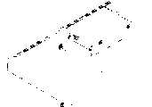
图1是本发明支架固定装置第一较佳实施方式的第一视角立体分解图。Fig. 1 is a perspective exploded view of the first preferred embodiment of the bracket fixing device of the present invention from a first viewing angle.
图2是本发明支架固定装置第一较佳实施方式的第二视角立体分解图。Fig. 2 is a perspective exploded view of the second viewing angle of the first preferred embodiment of the bracket fixing device of the present invention.
图3是本发明支架固定装置第一较佳实施方式的第三视角立体分解图。Fig. 3 is a perspective exploded view from a third viewing angle of the first preferred embodiment of the bracket fixing device of the present invention.
图4是本发明支架固定装置第一较佳实施方式的第一使用状态图。Fig. 4 is a diagram of the first use state of the first preferred embodiment of the bracket fixing device of the present invention.
图5是本发明支架固定装置第一较佳实施方式的第二使用状态图。Fig. 5 is a diagram of the second use state of the first preferred embodiment of the bracket fixing device of the present invention.
图6是本发明支架固定装置第二较佳实施方式的使用状态图。Fig. 6 is a view of the use state of the second preferred embodiment of the bracket fixing device of the present invention.
【具体实施方式】【Detailed ways】
请参阅图1与图2,本发明支架固定装置第一较佳实施方式是用于固定装设有一数据存储器20的第一支架40,其包括固定架10、固定件50、将该固定件50转接于该固定架10的转接件及两螺丝90。数据存储器20侧壁设有固定孔,可利用这些固定孔将数据存储器20螺锁于第一支架40。该固定架10在本实施方式中为电脑机箱,该转接件在本实施方式中为装设另一数据存储器20的第二支架30。Please refer to Fig. 1 and Fig. 2, the first preferred embodiment of the bracket fixing device of the present invention is used to fix the
该固定架10包括底壁12及垂直于该底壁12的侧壁13,该底壁12上设置若干卡固部14,每一卡固部14均为一向上凸起的桥,每一桥的桥面均为台阶面,其中较高的桥面相对较窄,较低的桥面相对较宽。这些卡固部14排成第一列、第二列及第三列,这三列均平行于该侧壁13,其中第一列设置于该底壁12靠近该侧壁13处,第二列与第一列相对设置,第三列设置于第二列的斜右侧处,该底壁12于该第一列及第二列卡固部的左侧分别设置一三角形的凸起15;该第三列卡固部的右侧也设置一三角形的凸起16,该侧壁13与该第三列卡固部14相对的位置设置三个自由端向下的“L”形卡扣部18,该底壁12于靠近该侧壁13处相对该三角形的凸起16设置另一三角形的凸起16。The
请一并参阅图3,该第二支架30大致呈“U”形,其包括底板32及垂直于该底板32两侧缘的第一侧板34和第二侧板36,该第一侧板34的自由端向外弯折形成一长形片状的弯折部342,该弯折部342对应底壁12上的第二列三个卡固部14开设三个卡槽344,这些卡槽344大致呈“L”形,其一端较窄另一端较宽。该第二侧板36的自由端也向外弯折形成一长形片状的弯折部362,该弯折部362对应底壁12上的第一列三个卡固部14开设三个大致呈“L”形的卡槽364,每一卡槽364均为一端较窄另一端较宽。该第二侧板36的一侧边向内弯折形成一贴住数据存储器20的贴合部369,该第二侧板36于靠近该贴合部369处设置一转接部,该转接部包括两平行的折片365及367,该折片365是由该贴合部369的自由端弯折形成并垂直于数据存储器20的端面,该折片365上开设一枢转孔366;该折片367是由该弯折部362的自由端的一侧弯折形成,该折片367与该折片365平行,该折片367对应该枢转孔366开设一枢转孔368。Please also refer to FIG. 3 , the
该第一支架40包括一第一板41及围设并垂直于该第一板41的第二板42、第三板43和第四板44,其中该第二板42与该第四板44相对设置。该第二板42的自由端向内弯折形成一弯折部422,该弯折部422对应底壁12上的第三列三个卡固部14开设三个大致呈“L”形的卡槽424,每一卡槽424均为一端较窄另一端较宽。该第三板43上设置一定位部432,该定位部432为一向外弯折形成的竖直的折片;该第三板43于该定位部432附近开设一方形的定位孔434。该第四板44的自由端向内弯折形成一弯折部442,该第四板44于靠近该弯折部442处对应该侧壁13上的卡扣部18开设三个卡槽444,每一卡槽444的一端较宽另一端较窄,每一卡槽444的较宽的一端延伸至该弯折部442并于该弯折部442处形成一开槽446。The
该固定件50的一角设置一枢转部52,该枢转部52为一通孔,该枢转部52的周围向外呈放射状形成三条肋,该三条肋经弯折后相交并于交点处形成一卡抵部54,该卡抵部54大致呈一截面为“L”形的板状,其卡抵面上设置一凸块542,该卡抵部54的弯折部分可作为操作时的手持部位。One corner of the
请一并参阅图4,组装时,将该固定件50置于该第二支架30的两折片365与367内,并使该固定件50的枢转部52对应于该两折片365与367上的枢转孔366与368,使用两螺丝90分别穿过该两枢转孔366与368锁入该固定件50的枢转部52内,将该固定件50枢接于该第二支架30。Please also refer to FIG. 4 , when assembling, place the
请一并参阅图5,固定时,将该第一支架40置入该固定架10内,使该固定架10的第三列三个卡固部14分别卡入该第一支架40的三个卡槽424内,并使该侧壁13的三个卡扣部18分别卡入该第一支架40的第四板44上的三卡槽444内,向右推动该第一支架40至其抵住该底壁12上的两三角形凸起16,每一卡固部14的较低的桥面卡入相应卡槽424中较窄的一端之上并卡住该弯折部422,每一卡扣部18穿过相应开槽446卡入相应卡槽444中较窄的一端将该第四板44卡于该侧壁13。将该第二支架30置入该固定架10内,使该底壁12上的第一列及第二列的卡固部14分别从该第二支架30相应的卡槽364及344的较宽的一端卡入,向左推动该第二支架30至抵住该底壁12的两三角形凸起15并使这些卡固部14的较宽的桥面卡入相应的卡槽364及344的较窄的一端之上将该第二支架30卡于该底壁12上。此时,该第二支架30剩下其右侧的自由度没有被限制,该第一支架40剩下其左侧的自由度没有被限制。旋转该固定件50使其卡抵部54卡抵于该第一支架40的第三板43至该卡抵部54上的凸块542卡入该第三板43上的定位孔434内对该固定件50进行定位,此时该固定件50将该第二支架30及第一支架40分别抵紧于该固定架10。Please refer to FIG. 5 together. When fixing, put the
拆卸时,旋转该固定件50使其卡抵部54与该第一支架40脱离接触,则该第二支架30的右侧的自由度被解锁,该第一支架40的左侧的自由度被解锁,可将两支架分别从该固定架10中取出。When dismounting, rotate the
该第三板43上的定位部432在该固定件50旋转的过程中起导向及定位的作用。The
请参阅图6,为本发明支架固定装置的第二较佳实施方式,其与该第一较佳实施方式的主要区别在于:该固定件50枢接于一转接件,该转接件在该第二较佳实施方式中为自该底壁12向上弯折形成的一折片60,该折片60上开设一枢转孔,该侧壁13对应该枢转孔开设一通孔,使用两螺丝90分别穿过该枢转孔及该通孔锁入该固定件50的枢转部52将该固定件50枢接于该固定架10。Please refer to FIG. 6 , which is the second preferred embodiment of the bracket fixing device of the present invention. The main difference between it and the first preferred embodiment is that the
Claims (13)
Translated fromChinesePriority Applications (2)
| Application Number | Priority Date | Filing Date | Title |
|---|---|---|---|
| CN200610034555ACN101039560B (en) | 2006-03-16 | 2006-03-16 | Bracket fixing device |
| US11/684,638US7495907B2 (en) | 2006-03-16 | 2007-03-12 | Mounting apparatus for storage device |
Applications Claiming Priority (1)
| Application Number | Priority Date | Filing Date | Title |
|---|---|---|---|
| CN200610034555ACN101039560B (en) | 2006-03-16 | 2006-03-16 | Bracket fixing device |
Publications (2)
| Publication Number | Publication Date |
|---|---|
| CN101039560Atrue CN101039560A (en) | 2007-09-19 |
| CN101039560B CN101039560B (en) | 2010-05-12 |
Family
ID=38517577
Family Applications (1)
| Application Number | Title | Priority Date | Filing Date |
|---|---|---|---|
| CN200610034555AExpired - Fee RelatedCN101039560B (en) | 2006-03-16 | 2006-03-16 | Bracket fixing device |
Country Status (2)
| Country | Link |
|---|---|
| US (1) | US7495907B2 (en) |
| CN (1) | CN101039560B (en) |
Cited By (7)
| Publication number | Priority date | Publication date | Assignee | Title |
|---|---|---|---|---|
| CN102236384A (en)* | 2010-04-23 | 2011-11-09 | 鸿富锦精密工业(深圳)有限公司 | Electronic device combination |
| CN101751087B (en)* | 2008-12-08 | 2012-01-11 | 和硕联合科技股份有限公司 | Stand assembly and electronics |
| CN102340941A (en)* | 2010-07-16 | 2012-02-01 | 鸿富锦精密工业(深圳)有限公司 | cabinet |
| CN103513721A (en)* | 2012-06-25 | 2014-01-15 | 鸿富锦精密工业(深圳)有限公司 | Fixing device for hard disk |
| CN103984392A (en)* | 2013-02-08 | 2014-08-13 | 英业达科技有限公司 | Electronic device |
| CN108663220A (en)* | 2018-05-23 | 2018-10-16 | 中国汽车技术研究中心有限公司 | A kind of novel data acquisition equipment rapid fixing |
| CN109902050A (en)* | 2017-12-11 | 2019-06-18 | 鸿富锦精密工业(武汉)有限公司 | Memory card transfer mechanism and memory card expansion device |
Families Citing this family (9)
| Publication number | Priority date | Publication date | Assignee | Title |
|---|---|---|---|---|
| US20090196684A1 (en)* | 2008-02-05 | 2009-08-06 | Inventec Corporation | Compression type fixing mechanism |
| CN102141827B (en)* | 2010-01-30 | 2013-11-06 | 鸿富锦精密工业(深圳)有限公司 | Hard disk fixing device |
| CN102929355A (en) | 2011-08-08 | 2013-02-13 | 鸿富锦精密工业(深圳)有限公司 | Data storage fixing device |
| CN103052296A (en)* | 2011-10-14 | 2013-04-17 | 鸿富锦精密工业(深圳)有限公司 | Electronic device shell |
| CN103186189A (en)* | 2011-12-28 | 2013-07-03 | 鸿富锦精密工业(深圳)有限公司 | Mainboard fixing device |
| TW201344682A (en)* | 2012-04-20 | 2013-11-01 | Primax Electronics Ltd | Hard disk support carrier |
| CN103513722A (en)* | 2012-06-25 | 2014-01-15 | 鸿富锦精密工业(深圳)有限公司 | Fixing device for hard disks |
| CN104281227A (en)* | 2013-07-03 | 2015-01-14 | 鸿富锦精密工业(深圳)有限公司 | Storer fixing device |
| US9454192B2 (en)* | 2014-03-29 | 2016-09-27 | Lenovo (Singapore) Pte. Ltd. | Component retention mechanism |
Family Cites Families (15)
| Publication number | Priority date | Publication date | Assignee | Title |
|---|---|---|---|---|
| US5764481A (en)* | 1996-10-23 | 1998-06-09 | Compaq Computer Corporation | Computer docking station with half-height bays and associated security system |
| CN2461044Y (en)* | 2000-12-14 | 2001-11-21 | 神达电脑股份有限公司 | Fixing structure of computer equipment carrying frame |
| US6700776B2 (en)* | 2001-05-17 | 2004-03-02 | Samsung Electronics Co., Ltd. | Computer |
| CN2567639Y (en)* | 2002-08-07 | 2003-08-20 | 鸿富锦精密工业(深圳)有限公司 | Magnetic frame fixing device |
| CN2673041Y (en)* | 2003-11-29 | 2005-01-19 | 鸿富锦精密工业(深圳)有限公司 | Data accessor fixer |
| CN2673042Y (en)* | 2003-11-29 | 2005-01-19 | 鸿富锦精密工业(深圳)有限公司 | Data accessor fixer |
| CN2708355Y (en)* | 2003-12-18 | 2005-07-06 | 纬创资通股份有限公司 | Detachable storage device that is easy to assemble and disassemble and computer device combined with storage device |
| US6999308B2 (en)* | 2004-01-15 | 2006-02-14 | Inventec Corporation | Modularized electronic device assembly architecture |
| TWM253195U (en)* | 2004-02-20 | 2004-12-11 | Hon Hai Prec Ind Co Ltd | Computer enclosure |
| CN2763877Y (en)* | 2004-12-11 | 2006-03-08 | 鸿富锦精密工业(深圳)有限公司 | Data memory fixator |
| CN2763882Y (en)* | 2004-12-24 | 2006-03-08 | 鸿富锦精密工业(深圳)有限公司 | Information memory lock |
| CN100501636C (en)* | 2005-06-10 | 2009-06-17 | 鸿富锦精密工业(深圳)有限公司 | data storage fixture |
| CN2862157Y (en)* | 2005-07-19 | 2007-01-24 | 鸿富锦精密工业(深圳)有限公司 | drive mount |
| US7233490B1 (en)* | 2006-01-09 | 2007-06-19 | In Win Development, Inc. | Positioning clamp for CD-ROM drives and diskette drives |
| CN2886644Y (en)* | 2006-01-13 | 2007-04-04 | 鸿富锦精密工业(深圳)有限公司 | Fixing device for butt joint back plate of hard disc |
- 2006
- 2006-03-16CNCN200610034555Apatent/CN101039560B/ennot_activeExpired - Fee Related
- 2007
- 2007-03-12USUS11/684,638patent/US7495907B2/ennot_activeExpired - Fee Related
Cited By (8)
| Publication number | Priority date | Publication date | Assignee | Title |
|---|---|---|---|---|
| CN101751087B (en)* | 2008-12-08 | 2012-01-11 | 和硕联合科技股份有限公司 | Stand assembly and electronics |
| CN102236384A (en)* | 2010-04-23 | 2011-11-09 | 鸿富锦精密工业(深圳)有限公司 | Electronic device combination |
| CN102340941A (en)* | 2010-07-16 | 2012-02-01 | 鸿富锦精密工业(深圳)有限公司 | cabinet |
| CN103513721A (en)* | 2012-06-25 | 2014-01-15 | 鸿富锦精密工业(深圳)有限公司 | Fixing device for hard disk |
| CN103513721B (en)* | 2012-06-25 | 2018-03-02 | 鸿富锦精密电子(天津)有限公司 | Device for fixing hard disk |
| CN103984392A (en)* | 2013-02-08 | 2014-08-13 | 英业达科技有限公司 | Electronic device |
| CN109902050A (en)* | 2017-12-11 | 2019-06-18 | 鸿富锦精密工业(武汉)有限公司 | Memory card transfer mechanism and memory card expansion device |
| CN108663220A (en)* | 2018-05-23 | 2018-10-16 | 中国汽车技术研究中心有限公司 | A kind of novel data acquisition equipment rapid fixing |
Also Published As
| Publication number | Publication date |
|---|---|
| CN101039560B (en) | 2010-05-12 |
| US7495907B2 (en) | 2009-02-24 |
| US20070217144A1 (en) | 2007-09-20 |
Similar Documents
| Publication | Publication Date | Title |
|---|---|---|
| CN101039560A (en) | Bracket fixing device | |
| CN2909351Y (en) | data storage fixture | |
| CN2919452Y (en) | data storage fixture | |
| US7855881B2 (en) | Mounting apparatus for back panel | |
| US7571884B2 (en) | Mounting apparatus for data storage device | |
| TWI429379B (en) | Bracket of electronic device, drawing assembly of electronic device, and computer case | |
| CN2785028Y (en) | Data memory fixing equipment | |
| US7495905B2 (en) | Mounting apparatus for storage device | |
| CN2919352Y (en) | data storage fixture | |
| US20070297127A1 (en) | Fixing mechanism for component | |
| TWM569055U (en) | Drawer for receiving storage module | |
| CN2874610Y (en) | Data storage fixer | |
| CN200969069Y (en) | Data storage fixing device | |
| CN2886646Y (en) | Bracket fixing device | |
| US11632869B2 (en) | Detachably fixing device and electronic apparatus casing therewith | |
| CN2643374Y (en) | Hard disc drawing structure | |
| CN2862258Y (en) | data storage fixture | |
| CN2862260Y (en) | data storage fixture | |
| CN2849910Y (en) | Fixer for data memory | |
| CN2831225Y (en) | Magnetic rack rotatory device | |
| CN101075150B (en) | computer case | |
| CN2630916Y (en) | Expanding card fixing device | |
| CN113835482B (en) | HBA card tool-free locking device and HBA card mounting structure | |
| CN2874715Y (en) | Data storage fixing device | |
| CN2831212Y (en) | Magnetic frame fixer |
Legal Events
| Date | Code | Title | Description |
|---|---|---|---|
| C06 | Publication | ||
| PB01 | Publication | ||
| C10 | Entry into substantive examination | ||
| SE01 | Entry into force of request for substantive examination | ||
| C14 | Grant of patent or utility model | ||
| GR01 | Patent grant | ||
| C17 | Cessation of patent right | ||
| CF01 | Termination of patent right due to non-payment of annual fee | Granted publication date:20100512 Termination date:20140316 |