CN101038677B - Interface data conversion method and device thereof - Google Patents
Interface data conversion method and device thereofDownload PDFInfo
- Publication number
- CN101038677B CN101038677BCN2006100114915ACN200610011491ACN101038677BCN 101038677 BCN101038677 BCN 101038677BCN 2006100114915 ACN2006100114915 ACN 2006100114915ACN 200610011491 ACN200610011491 ACN 200610011491ACN 101038677 BCN101038677 BCN 101038677B
- Authority
- CN
- China
- Prior art keywords
- point
- processing module
- data
- data file
- seismic inversion
- Prior art date
- Legal status (The legal status is an assumption and is not a legal conclusion. Google has not performed a legal analysis and makes no representation as to the accuracy of the status listed.)
- Active
Links
Images


Landscapes
- Geophysics And Detection Of Objects (AREA)
Abstract
Description
Translated fromChinese技术领域technical field
本发明涉及一种接口数据转换方法及其装置,特别是涉及一种用于三维建模处理模块/软件与地震反演处理模块/软件之间接口数据进行转换的方法及转换装置。The invention relates to an interface data conversion method and device thereof, in particular to a method and a conversion device for converting interface data between a three-dimensional modeling processing module/software and an seismic inversion processing module/software.
背景技术Background technique
三维建模处理模块/软件采用三角网格化的几何模型描述复杂的地质构造。由于地质构造的复杂性,决定了几何模型采用复杂拓扑结构记录地层形状和断层形状。同时,几何模型还要记录地层与地层、地层与断层以及断层与断层之间的关系。The 3D modeling processing module/software uses a triangular meshed geometric model to describe complex geological structures. Due to the complexity of the geological structure, it is determined that the geometric model adopts a complex topological structure to record the shape of the formation and the shape of the fault. At the same time, the geometric model also records the relationship between strata and strata, stratum and fault, and fault and fault.
一般地震反演处理模块/软件采用离散的层面栅格模型记录地质构造信息,如P701格式的模型,这种模型在X、Y、Z三个方向上都是离散的。层面栅格模型比较简单,但无法全面记录复杂的地质构造信息。在断层存在的地质构造模型中,无法根据P701中的信息在地层中按照一定的比例添加一个新的层,所以层面栅格模型不能准确地描述断层附近地质结构。Generally, the seismic inversion processing module/software uses a discrete layer grid model to record geological structure information, such as a model in P701 format, which is discrete in the three directions of X, Y, and Z. The level grid model is relatively simple, but it cannot fully record complex geological structure information. In the geological structure model where faults exist, it is impossible to add a new layer in the stratum according to a certain proportion according to the information in P701, so the slice grid model cannot accurately describe the geological structure near the fault.
如果把几何模型转换为现有的层面栅格模型,如P701格式的模型,那么很多重要的地质构造信息会丢失;如果让地震反演处理模块直接把几何模型作为输入,那么需要对地震反演处理模块作较大的修改。If the geometric model is converted to the existing slice grid model, such as the P701 format model, then a lot of important geological structure information will be lost; if the seismic inversion processing module directly takes the geometric model as input, then the seismic inversion The processing module has been greatly modified.
发明内容Contents of the invention
本发明所要解决的技术问题在于提供一种接口数据转换方法及其装置,用于简单、方便进行三维建模处理模块/软件与地震反演处理模块/软件之间接口数据转换。The technical problem to be solved by the present invention is to provide an interface data conversion method and its device for simple and convenient interface data conversion between the three-dimensional modeling processing module/software and the seismic inversion processing module/software.
为了实现上述目的,本发明提供了一种接口数据转换方法,适用于三维建模处理模块与地震反演处理模块之间数据的转换,其特征在于,包括如下步骤:In order to achieve the above object, the present invention provides an interface data conversion method, which is suitable for data conversion between the three-dimensional modeling processing module and the seismic inversion processing module, and is characterized in that it includes the following steps:
步骤一,通过所述三维建模处理模块生成并输出三维地质模型的增强栅格格式数据文件;
步骤二,通过所述地震反演处理模块读入所述增强栅格格式数据文件,并根据所述增强栅格格式数据文件进行地震反演运算;
所述增强栅格格式数据文件具有在X、Y方向上与地震数据一致、柵格数目与地震数据相同的离散数据结构,并包含在Z方向上连续记录有三维地质模型的关键点和点对的结构信息,该关键点为栅格节点处假想的Z方向上投射线与三维地质模型的地层面和断层面的交点,同一栅格节点处每两个上下相邻的关键点组合成一个点对;所述步骤二进一步包括将名字、类型相同的关键点归结为同一个地质元素,所属层位相同的所有点对归结为同一个地质元素。The enhanced grid format data file has a discrete data structure that is consistent with the seismic data in the X and Y directions, and the number of grids is the same as that of the seismic data, and contains key points and point pairs that continuously record the three-dimensional geological model in the Z direction The key point is the intersection point of the projection line in the Z direction at the imaginary grid node and the stratum and fault planes of the 3D geological model. Every two adjacent key points at the same grid node are combined into one point Yes; said
所述的接口数据转换方法,其中,所述步骤一具体又包括:所述三维建模处理模块建立一三维地质模型,在该地质模型中的XY面上划分出与地震数据一致的栅格,在每个栅格节点处假想Z向投射线穿透所有的地层和断层;所述每条投射线与地层面和断层面的交点为关键点;并将该三维地质模型中在同一栅格节点处每两个上下相邻的关键点组合成点对,记录下所有关键点、点对并保存于增强栅格格式的文件中,生成增强栅格格式数据文件。The interface data conversion method, wherein, the first step specifically includes: the three-dimensional modeling processing module establishes a three-dimensional geological model, and divides a grid consistent with the seismic data on the XY plane of the geological model, At each grid node, the imaginary Z-direction projection line penetrates all formations and faults; the intersection of each projection line with the formation layer and fault plane is a key point; and in the three-dimensional geological model at the same grid node Every two adjacent key points up and down are combined into point pairs, and all key points and point pairs are recorded and saved in the enhanced raster format file to generate the enhanced raster format data file.
所述的接口数据转换方法,其中,所述步骤二具体为:所述地震反演处理模块从所述增强栅格格式数据文件中读入三维地质模型的关键点的数据和点对的数据,并将所述关键点的数据和点对的数据作为输入进行地震反演运算。The interface data conversion method, wherein, the second step is specifically: the seismic inversion processing module reads in the key point data and point pair data of the three-dimensional geological model from the enhanced grid format data file, The data of the key points and the data of the point pairs are used as input to perform seismic inversion calculation.
所述的接口数据转换方法,其中,所述步骤二进一步包括:所述点对中结束点的深度减去起始点的深度的绝对值为各个栅格节点处地层的厚度。In the interface data conversion method, the second step further includes: the absolute value of the depth of the end point minus the depth of the starting point in the point pair is the thickness of the formation at each grid node.
所述的接口数据转换方法,其中,所述步骤二进一步包括:通过所述增强栅格格式数据文件结合测井曲线数据求取三维地质模型中任意点的属性值的步骤。Said interface data conversion method, wherein said
所述的接口数据转换方法,其中,所述求取三维地质模型中任意点的属性值的步骤具体又包括:The interface data conversion method, wherein the step of obtaining the attribute value of any point in the three-dimensional geological model specifically includes:
步骤701,根据该任意点的XYZ坐标确定其所处栅格节点、所处点对,并进一步确定该任意点所处地层及在所处地层中的比例;Step 701, according to the XYZ coordinates of the arbitrary point, determine the grid node and the point pair where it is located, and further determine the stratum where the arbitrary point is located and the proportion in the stratum where it is located;
步骤702,根据所述比例和所处地层计算出一个新的层面;及Step 702, calculating a new layer according to the ratio and the stratum; and
步骤703,求取测井曲线轨迹与该新层面的交点,根据所述交点的属性值通过插值得到该任意点的属性值。Step 703, calculating the intersection point between the log curve trajectory and the new layer, and obtaining the attribute value of the arbitrary point through interpolation according to the attribute value of the intersection point.
所述的接口数据转换方法,其中,所述步骤二中,还包括通过所述地震反演处理模块根据所述增强栅格格式数据文件求取地层中与顶面和底面距离成固定比例的计算层面的步骤。The interface data conversion method, wherein, in the second step, it also includes calculating the fixed ratio of the distance between the top surface and the bottom surface in the formation through the seismic inversion processing module according to the enhanced grid format data file level steps.
所述的接口数据转换方法,其中,所述步骤二中,还包括通过所述地震反演处理模块根据所述增强栅格格式数据文件求取地层中与顶面等距的计算层面的步骤。The interface data conversion method, wherein, in the second step, further includes the step of calculating the calculation horizon equidistant from the top surface in the formation by the seismic inversion processing module according to the enhanced grid format data file.
所述的接口数据转换方法,其中,所述步骤二中,还包括通过所述地震反演处理模块根据所述增强栅格格式数据文件求取地层中与底面等距的计算层面的步骤。The interface data conversion method, wherein, in the second step, further includes the step of calculating the calculation horizon equidistant from the bottom surface in the stratum according to the enhanced grid format data file through the seismic inversion processing module.
为了实现上述目的,本发明还提供了一种接口数据转换装置,其特征在于,包括一三维建模处理模块、一与所述三维建模处理模块连接的地震反演处理模块,所述三维建模处理模块又包括一接口数据转换模块、一接口数据输出模块;In order to achieve the above object, the present invention also provides an interface data conversion device, which is characterized in that it includes a three-dimensional modeling processing module, a seismic inversion processing module connected with the three-dimensional modeling processing module, and the three-dimensional modeling processing module The mold processing module further includes an interface data conversion module and an interface data output module;
所述接口数据转换模块用于生成一三维地质模型的增强栅格格式数据文件;所述接口数据输出模块用于输出所述增强栅格格式数据文件;所述地震反演处理模块用于读入所述增强栅格格式数据文件,并根据所述增强栅格格式数据文件进行地震反演运算;The interface data conversion module is used to generate an enhanced grid format data file of a three-dimensional geological model; the interface data output module is used to output the enhanced grid format data file; the seismic inversion processing module is used to read in The enhanced grid format data file, and perform seismic inversion calculation according to the enhanced grid format data file;
所述增强栅格格式数据文件具有在X、Y方向上与地震数据一致、柵格数目与地震数据相同的离散数据结构,并包含在Z方向上连续记录有三维地质模型的关键点和点对的结构信息,该关键点为栅格节点处假想的Z方向上投射线与三维地质模型的地层面和断层面的交点,同一栅格节点处每两个上下相邻的关键点组合成一个点对;所述地震反演处理模块将名字、类型相同的关键点归结为同一个地质元素,所属层位相同的所有点对归结为同一个地质元素。The enhanced grid format data file has a discrete data structure that is consistent with the seismic data in the X and Y directions, and the number of grids is the same as that of the seismic data, and contains key points and point pairs that continuously record the three-dimensional geological model in the Z direction The key point is the intersection point of the projection line in the Z direction at the imaginary grid node and the stratum and fault planes of the 3D geological model. Every two adjacent key points at the same grid node are combined into one point Yes; the seismic inversion processing module attributes key points with the same name and type to the same geological element, and all point pairs with the same horizon are attributed to the same geological element.
所述的接口数据转换装置,其中,所述地震反演处理模块通过一用于读取增强柵格格式数据文件的接口读入所述增强栅格格式文件。In the interface data conversion device, the seismic inversion processing module reads the enhanced raster format file through an interface for reading the enhanced raster format data file.
本发明中具有增强栅格格式的数据文件包含了三维地质模型的必要的结构信息,该增强栅格格式是一种简单、离散又可以准确地表达三维地质模型拓扑结构的数据格式;该增强栅格格式能够以简单的结构描述复杂的三维地质模型,极大方便了地震反演处理模块的使用。In the present invention, the data file with the enhanced grid format contains the necessary structural information of the three-dimensional geological model, and the enhanced grid format is a simple, discrete data format that can accurately express the topological structure of the three-dimensional geological model; the enhanced grid format The lattice format can describe complex 3D geological models with a simple structure, which greatly facilitates the use of seismic inversion processing modules.
以下结合附图和具体实施例对本发明进行详细描述,但不作为对本发明的限定。The present invention will be described in detail below in conjunction with the accompanying drawings and specific embodiments, but not as a limitation of the present invention.
附图说明Description of drawings
图1为本发明增强栅格格式X、Y方向栅格示意图;Fig. 1 is a schematic diagram of grids in the X and Y directions of the enhanced grid format of the present invention;
图2为本发明增强栅格格式纵向Z方向的剖面示意图;Fig. 2 is a schematic cross-sectional view of the longitudinal Z direction of the enhanced grid format of the present invention;
图3为本发明增强栅格格式的应用示意图;Fig. 3 is a schematic diagram of the application of the enhanced grid format of the present invention;
图4为本发明三维建模处理模块与地震反演处理模块之间接口数据转换的方法流程图;Fig. 4 is the flow chart of the method for interface data conversion between the three-dimensional modeling processing module and the seismic inversion processing module of the present invention;
图5为本发明的一具体实施例;Fig. 5 is a specific embodiment of the present invention;
图6为本发明求取三维地质模型中任意一点属性值的流程图;Fig. 6 is the flow chart that the present invention obtains the attribute value of any point in the three-dimensional geological model;
图7为本发明的接口数据转换装置示意图。Fig. 7 is a schematic diagram of the interface data conversion device of the present invention.
具体实施方式Detailed ways
请参阅图1所示,为本发明增强栅格格式X、Y方向栅格示意图。增强栅格格式是一种描述地质构造的数据格式。如图1所示,在XY方向上,本发明采用与地震数据(如SEGY和P701格式)一致的栅格格式,栅格的数目与地震数据相同,在每一个栅格的节点处,假设Z向有一条竖直的投射线穿透所有的地层和断层。Please refer to FIG. 1 , which is a schematic diagram of grids in the X and Y directions of the enhanced grid format of the present invention. Enhanced raster format is a data format that describes geological formations. As shown in Figure 1, in the XY direction, the present invention adopts the grid format consistent with the seismic data (such as SEGY and P701 format), and the number of the grid is the same as the seismic data, and at the nodes of each grid, it is assumed that Z There is a vertical projection line through all strata and faults.
请参阅图2所示,为本发明增强栅格格式纵向Z方向的剖面示意图。并结合图1,如图2所示,每条投射线与地层面和断层面的交点叫做关键点P(Point),如P1、P2、P3、P4、P5、P6、P7、P8、P9、P10。关键点P的信息包括:坐标X,Y,Z,交点类型Type,所交层面的名字Name。交点类型Type用于记录该交点与地层面的交点或该交点与断层面的交点;所交层面的名字Name用于记录地层或者断层的名字。如P1与地层L1相交,P1的名字Name为L1。Please refer to FIG. 2 , which is a schematic cross-sectional view in the longitudinal Z direction of the enhanced grid format of the present invention. Combined with Figure 1, as shown in Figure 2, the intersection of each projection line with the stratum and fault planes is called a key point P (Point), such as P1, P2, P3, P4, P5, P6, P7, P8, P9, P10. The information of the key point P includes: coordinates X, Y, Z, intersection type Type, name of the intersecting layer Name. The intersection type Type is used to record the intersection point of the intersection point and the stratum layer or the intersection point of the intersection point and the fault plane; the name of the intersecting layer name is used to record the name of the stratum or fault. If P1 intersects with stratum L1, the name of P1 is L1.
在同一个栅格节点处的每两个上下相邻的关键点组成一个点对PC(PointCouple),点对PC记录的信息包括:起始点Pup、结束点Pdn、起始点比例Rup、结束点比例Rdn、所属层位Lname。其中所属层位Lname通常以一个层位的顶面的名字代表这个层面。关键点、点对的文件格式如下:Every two adjacent key points at the same grid node form a point pair PC (PointCouple). The information recorded by the point pair PC includes: starting point Pup, ending point Pdn, starting point ratio Rup, and ending point ratio Rdn, layer Lname to which it belongs. The level Lname to which it belongs usually represents the level by the name of the top surface of a level. The file formats of key points and point pairs are as follows:
Pointspoints
{{
//No. x y z 类型 Name//No. x y y z Type Name
0, 12530, 3580, -900.1, L, layer1;0, 12530, 3580, -900.1, L, layer1;
1, 12530, 3580, -990.5, F, fault1;1, 12530, 3580, -990.5, F, fault1;
}}
Point CouplesPoint Couples
{{
//Pup /Pdn /Rup /Rdn/LayerName//Pup /Pdn /Rup /Rdn/LayerName
0, 1, 0, 1, layer1;0, 1, 0, 1, layer1;
1, 2, 0, 1, layer2;1, 2, 0, 1, layer2;
20030,20031,0,0.73,layer5;20030, 20031, 0, 0.73, layer5;
30016,30017,0.335,1,layer6;30016, 30017, 0.335, 1, layer6;
}}
增强栅格格式是一种结合了离散和连续特点的离散数据结构:在XY方向,数据结构是离散的,为与地震数据一致的栅格格式,栅格的数目与地震数据相同;在Z向上,数据结构为可以在Z方向上连续记录的三维地质模型的结构信息。增强栅格格式的数据包含两种主要信息:地层面和断层面上的关键点及由这些关键点组成的点对。这些关键点和点对包含了三维地质构造模型的结构信息。通过增强栅格格式的数据可以把三维建模处理模块/软件与地震反演处理模块/软件(如Jason软件)紧密结合起来。The enhanced grid format is a discrete data structure that combines discrete and continuous features: in the XY direction, the data structure is discrete, which is the same grid format as the seismic data, and the number of grids is the same as that of the seismic data; in the Z direction , the data structure is the structural information of the three-dimensional geological model that can be continuously recorded in the Z direction. Data in enhanced raster format contains two main types of information: keypoints on stratigraphic and fault planes and point pairs consisting of these keypoints. These key points and point pairs contain the structural information of the 3D geological structure model. By enhancing the data in raster format, the 3D modeling processing module/software can be closely combined with the seismic inversion processing module/software (such as Jason software).
请参阅3所示,为本发明增强栅格格式的应用示意图。结合图1、2所示,该应用通过应用增强栅格数据格式,可以方便生成与顶面和底面距离成固定比例的计算层面、与顶面等距的计算层面和与底面等距的计算层面。该图3所示的应用30包括如下几个方面:Please refer to 3, which is a schematic diagram of the application of the enhanced grid format of the present invention. As shown in Figures 1 and 2, by applying the enhanced raster data format, the application can easily generate a calculation level that is proportional to the distance between the top and bottom surfaces, a calculation level that is equidistant from the top surface, and a calculation level that is equidistant from the bottom surface . The
31,求取与顶面和底面的距离成固定比例的计算层面;获取所要计算的层面所在的地层名称和处于顶面和底面之间的比例,就可以根据上述增强栅格格式数据结构求出计算层面在各个节点处的深度值。31. Obtain the calculation level with a fixed ratio to the distance between the top surface and the bottom surface; obtain the stratum name of the level to be calculated and the ratio between the top surface and the bottom surface, and then calculate according to the above-mentioned enhanced raster format data structure Calculate the depth value of the slice at each node.
例如,求图2中在地层L1中与顶面和底面的距离比为0.3的计算层面。以计算层面上的点pt1和pt3为例,计算层面位于地层L1中,处于顶、底之间 比例为0.3的位置:For example, in Fig. 2, calculate the calculation horizon whose distance ratio to the top surface and the bottom surface is 0.3 in the stratum L1. Taking the points pt1 and pt3 on the calculation level as an example, the calculation level is located in the stratum L1, at the position between the top and the bottom with a ratio of 0.3:
点pt1在投射线S1上,并且投射线S1上处于地层L1中的点对为(P1,P2),根据P1和P2的深度、比例和计算层面的比例0.3,可以得到计算层面在这一点处的深度值:The point pt1 is on the projection line S1, and the point pair on the projection line S1 in the stratum L1 is (P1, P2). According to the depth and ratio of P1 and P2, and the calculation layer ratio of 0.3, it can be obtained that the calculation layer is at this point The depth value:
Zpt1=ZP1+(ZP2-ZP1)(Rpt1-RP1)/(RP2-RP1) (1)Zpt1=ZP1+(ZP2-ZP1)(Rpt1-RP1)/(RP2-RP1) (1)
如果Rpt1的值小于RP1,或者Rpt1的值大于RP2,说明此投射线S1所在的栅格节点处,地层L1中没有符合比例的点。If the value of Rpt1 is less than RP1, or the value of Rpt1 is greater than RP2, it means that there is no proportional point in the stratum L1 at the grid node where the projection line S1 is located.
点pt3在投射线S3上,并且投射线S3上处于L1地层中的点对为(P6,P7),根据P6和P7的深度、比例和计算层面的比例0.3,可以得到计算层面在这一点处的深度值:The point pt3 is on the projection line S3, and the point pair on the projection line S3 in the L1 formation is (P6, P7). According to the depth and ratio of P6 and P7, and the calculation layer ratio of 0.3, it can be obtained that the calculation layer is at this point The depth value:
Zpt3=ZP6+(ZP7-ZP6)(Rpt3-RP6)/(RP7-RP6) (2)Zpt3=ZP6+(ZP7-ZP6)(Rpt3-RP6)/(RP7-RP6) (2)
依次计算出所有栅格节点处的与顶底距离比为0.3的点的深度,就得到了所求层面。Calculate the depth of the points at all grid nodes with a distance ratio of 0.3 to the top and bottom in turn to obtain the desired layer.
32,求取一个与顶面等距的计算层面;获取所要计算的层面所在的地层名称和离顶面的距离,就可以根据上述增强栅格格式数据结构求出计算层面在各个栅格节点处的深度值。32. Obtain a calculation level equidistant from the top surface; obtain the stratum name where the level to be calculated is located and the distance from the top surface, and then calculate the calculation level at each grid node according to the above enhanced grid format data structure the depth value.
例如,计算地层Layer1中离顶面的距离为d米的计算平面。For example, calculate the calculation plane whose distance from the top surface is d meters in the stratum Layer1.
在某一个栅格节点处,投射线S与地层Layer1的相交的点对是(Pup,Pdn),那么这一节点处计算平面上的点p的深度值计算方法为:At a certain grid node, the point pair where the projection line S intersects with the stratum Layer1 is (Pup, Pdn), then the calculation method for the depth value of point p on the calculation plane at this node is:
|Zp|=|Zup|+d (3)|Zp|=|Zup|+d (3)
如果|Zp|大于|Zdn|,表明在这一栅格节点处,地层Layer1中没有离顶面的距离为d的点。If |Zp| is greater than |Zdn|, it means that at this grid node, there is no point with a distance d from the top surface in Layer1.
依次计算得到所有节点处的计算平面的深度值。The depth values of the calculation planes at all nodes are calculated sequentially.
33,求取一个与底面等距的计算层面。33. Obtain a calculation level equidistant from the bottom surface.
与求取与顶面等距的计算平面的方法类似,计算与底面等距的层面的公式为:Similar to the method of obtaining the calculation plane equidistant from the top surface, the formula for calculating the plane equidistant from the bottom surface is:
|Zp|=|Zdn|-d (4)|Zp|=|Zdn|-d
如果|Zp|小于|Zup|,表明在这一栅格节点处,地层Layer1中没有离底面距离为d的点。If |Zp| is smaller than |Zup|, it means that at this grid node, there is no point in Layer1 whose distance from the bottom is d.
应用本发明提出的增强栅格格式和测井曲线数据可以插值三维地质模型 中任何一点p的属性值。首先判断p点位于哪一条投射线上,然后根据p的深度值得到p位于哪一个地层、哪一个点对之间以及在地层中的比例。根据比例和所处层位,就可以计算出一个新的层面。求得井轨迹与这一新层面的交点,根据这些交点处的属性值,可以插值得到p点的属性值。如果p或者井点不正好在栅格节点处,可以通过对栅格节点的插值得到这些点的属性值。The attribute value of any point p in the three-dimensional geological model can be interpolated by applying the enhanced grid format and logging curve data proposed by the present invention. First determine which projection line p is located on, and then obtain which layer p is located in, which point pair, and the ratio in the layer according to the depth value of p. According to the proportion and the layer, a new layer can be calculated. The intersection points of the well trajectory and this new layer are obtained, and the attribute value of point p can be obtained by interpolation according to the attribute values at these intersection points. If p or well points are not exactly at the grid nodes, the attribute values of these points can be obtained by interpolating the grid nodes.
请参阅图4所示,为本发明三维建模处理模块与地震反演处理模块之间接口数据转换的方法流程图。并结合图2所示,该流程包括如下步骤:Please refer to FIG. 4 , which is a flow chart of the interface data conversion method between the three-dimensional modeling processing module and the seismic inversion processing module of the present invention. And combined with that shown in Figure 2, the process includes the following steps:
步骤401、首先,通过三维建模处理模块根据复杂的地质构造信息建立三维地质模型,生成并输出三维地质模型的增强栅格格式数据文件;
生成三维地质模型的增强栅格格式数据文件的步骤具体包括:The steps of generating the enhanced grid format data file of the 3D geological model specifically include:
(11)、建立三维地质模型(几何模型),在水平面XY向上,本发明采用与地震数据一致的栅格,在每一个栅格的节点处,假设Z向有一条竖直的投射线穿透所有的地层和断层。每条投射线与地层面和断层面的交点被记录下来,这些点叫做关键点P(Point),即本发明计算栅格节点在地层面和断层面上的竖直投影关键点P并且记录这些关键点的信息;(11), set up three-dimensional geological model (geometric model), on the horizontal plane XY upwards, the present invention adopts the grid consistent with seismic data, at the node place of each grid, suppose Z direction has a vertical projection line to penetrate All strata and faults. The intersection points of each projected line and the stratum and fault planes are recorded, and these points are called key points P (Point), that is, the present invention calculates the vertical projection key points P of the grid nodes on the stratum and fault planes and records these key points of information;
(12)、将在同一个栅格节点处的每两个上下相邻的关键点P组合成一个点对PC(Point Couple),并记录这个点对;(12), every two adjacent key points P at the same grid node are combined into a point pair PC (Point Couple), and record this point pair;
(13)、记录所有的关键点,记录所有栅格节点处的所有点对,并保存于增强栅格格式的文件或者数据结构中,这样就从三维模型中生成了增强栅格数据。这一数据可以被保存为增强栅格格式的数据文件。(13) Record all key points, record all point pairs at all grid nodes, and save them in a file or data structure in enhanced grid format, thus generating enhanced grid data from the 3D model. This data can be saved as a data file in the enhanced raster format.
投射线S1的一个点对是(P1,P2),起始点Pup=P1,结束点Pdn=P2,起始点比例Rup=0,结束点比例Rdn=1,所属层位Lname=L1(通常以一个层位的顶面的名字代表这个层面)。A point pair of projection line S1 is (P1, P2), starting point Pup=P1, ending point Pdn=P2, starting point ratio Rup=0, ending point ratio Rdn=1, belonging layer Lname=L1 (usually with a The name of the top face of the layer represents the layer).
投射线S3的一个点对是(P6,P7),起始点Pup=P6,结束点Pdn=P7,起始点比例Rup=0,结束点比例Rdn=0.4(假定在断层右侧P7在L1、L2之间的比例为0.4),所属层位Lname=L1。A point pair of projection line S3 is (P6, P7), starting point Pup=P6, ending point Pdn=P7, starting point ratio Rup=0, ending point ratio Rdn=0.4 (assuming that P7 is on the right side of the fault in L1, L2 The ratio between them is 0.4), and the layer to which they belong is Lname=L1.
投射线S3的另一个点对是(P7,P8),起始点Pup=P7,结束点Pdn=P8,起始点比例Rup=0.8(假定在断层右侧P7在L1、L2之间的比例为0.8),结束点比例Rdn=1,所属层位Lname=L1。Another point pair of projection line S3 is (P7, P8), starting point Pup=P7, ending point Pdn=P8, starting point ratio Rup=0.8 (assuming that the ratio of P7 between L1 and L2 on the right side of the fault is 0.8 ), the end point ratio Rdn=1, and the layer Lname=L1 to which it belongs.
对于一个M行N列的网格,每一个节点的位置有一个投射线Smn,投射 线Smn与地层和断层的交点P被记录下来,每两个相邻的交点P组成的点对PC也被记录下来。这样增强栅格格式的数据就生成了。For a grid with M rows and N columns, each node position has a projection line Smn, the intersection point P of the projection line Smn and the formation and fault is recorded, and the point pair PC formed by every two adjacent intersection points P is also recorded record it. In this way, the data in the enhanced raster format is generated.
在步骤401中,由三维地质建模处理模块输出三维地质模型的增强栅格格式数据文件,即,具有增强栅格格式的数据文件。In
输出三维地质模型的增强栅格格式数据文件的步骤具体又包括:The steps of outputting the enhanced raster format data file of the 3D geological model specifically include:
(21),首先三维建模处理模块根据地震数据栅格的位置选择一个栅格节点,得到栅格节点的XY坐标,即根据地震数据中栅格节点的位置确定一个假想投射线的XY坐标;然后计算假想的投射线与其所相交的地层和断层的交点的坐标,包括Z坐标和XY坐标;(21), at first the three-dimensional modeling processing module selects a grid node according to the position of the seismic data grid, obtains the XY coordinates of the grid node, namely determines the XY coordinates of an imaginary projection line according to the position of the grid node in the seismic data; Then calculate the coordinates of the intersection point of the imaginary projected line and the stratum and fault that it intersects, including Z coordinates and XY coordinates;
(22),把交点的坐标、交点类型和所交层面的名称等信息依次记录到某种数据结构中,如链表或者数组或者其他的公知的数据结构(由三维建模处理模块的数据结构决定);接下来把这条投射线上处于研究范围内的每两个上下相邻的点作为点对,把点对的起始点、结束点、起始点比例、结束点比例、所属层位等信息也记录到一公知的数据结构中;(22), information such as the coordinates of the intersection point, the type of intersection point and the name of the intersecting layer are recorded in a certain data structure in turn, such as a linked list or an array or other known data structures (determined by the data structure of the three-dimensional modeling processing module ); Next, every two adjacent points on this projection line within the research range are regarded as point pairs, and information such as the start point, end point, start point ratio, end point ratio, and layer of the point pair Also recorded in a well-known data structure;
(23),依次计算所有的栅格节点处的点和点对,并记录到数据结构中;最后把数据结构中的点和点对的数据写入到增强栅格格式的文件中。(23), calculate the points and point pairs at all grid nodes in turn, and record them in the data structure; finally write the data of the points and point pairs in the data structure to the file in the enhanced grid format.
步骤402、地震反演处理模块从增强栅格格式的数据文件中读入所有的关键点和点对,并进行地震反演运算。
该步骤中,地震反演处理模块需要建立一个可以读取增强栅格格式数据文件的接口,以读取增强栅格格式数据文件;该接口能够实现从增强栅格格式数据文件中读入所有的关键点和点对,然后把这些数据作为一个输入进行地震反演的运算。建立读取增强栅格格式数据文件的接口的步骤具体为:In this step, the seismic inversion processing module needs to establish an interface that can read the enhanced raster format data file to read the enhanced raster format data file; this interface can read all the Key points and point pairs are then used as an input for seismic inversion operations. The specific steps for establishing an interface for reading enhanced raster format data files are as follows:
(31),把名字、类型相同的点归结为同一个地质元素,如所有名字、类型相同的点组成同一个地层面或者断层面;并把这些点的信息分别放入到这些地质元素的数据结构中,如属于同一个地层面的点放入到这个地层面的数据结构中;把所属层位相同的所有点对归结为同一个地质元素,如所有所属层位相同的点对组成同一个地层,把点对的信息放入到相应的地层数据结构中;(31), attribute the points with the same name and type to the same geological element, such as all points with the same name and type form the same stratum or fault plane; and put the information of these points into the data of these geological elements In the structure, if the points belonging to the same layer are put into the data structure of this layer; all point pairs belonging to the same layer are attributed to the same geological element, such as all point pairs belonging to the same layer form the same Strata, put the point-pair information into the corresponding stratum data structure;
(32),从点和点对的信息中可以得到地层的位置、形态、厚度等信息,可以得到断层的位置、形态等信息,还可以得到地层与断层的相互位置关系的信息,这样地质模型就被读入到地震反演模块中了。(32), from the information of points and point pairs, information such as the position, shape, and thickness of the stratum can be obtained, information such as the position and shape of the fault can be obtained, and information on the mutual positional relationship between the stratum and the fault can also be obtained, so that the geological model It is read into the seismic inversion module.
也可以在从EGF格式的文件中读入点和点对的同时就把点和点对分别放入到其所属的不同的地质元素的数据结构中。It is also possible to put the points and point pairs into the data structures of different geological elements to which they belong while reading in the points and point pairs from the EGF format file.
步骤402中,把名字、类型相同的点归结为同一个地质元素,如将所有名字为Layer1,类型为L(地层)的点组成同一个地层面Layer1;所有名字为F1,类型为F(断层)的点组成同一个断层面F1。地层面可以代表地层顶面或者地层底面。地层面和断层面是没有厚度的。In
步骤402中,把所属层位相同的所有点对PC归结为同一个地质元素,如将所有所属层位为Layer1的点对组成地层Layer1,该地层是有厚度的,各个栅格节点处地层的厚度为点对PC中结束点的深度减去起始点的深度的绝对值,这样地质模型就生成了。地质模型中任意一点在空间中的位置和属性可以通过对该点的邻近点插值得到。In
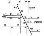
请参阅图5所示,为本发明的一具体实施例。该实施例描述了数据转换的具体实施方式。如图5所示的三维地质模型是一个连续的三维地质模型(几何模型),该模型中包含一个断层F1和三个地层d2-1、d2-1和d2-3,断层F1与三个地层分别相交。本发明以地层d2-1和d2-2为研究对象,在X、Y方向上,本发明取7×7的栅格,栅格的距离为250米,在Z方向上,本发明研究d2-1和d2-2两个地层。首先,使用三维建模处理模块建立此三维地质模型;其次,再使用三维建模处理模块输出一个增强栅格格式的数据文件,这个文件中包含了三维地质模型的关键点信息和点对信息。地震反演处理模块读入这个增强栅格格式的数据文件,就可以得到立体的三维地质模型,结合其他的数据就可以进行地震反演运算了。Please refer to FIG. 5 , which is a specific embodiment of the present invention. This example describes the specific implementation of data conversion. The three-dimensional geological model shown in Figure 5 is a continuous three-dimensional geological model (geometric model), which contains a fault F1 and three strata d2-1, d2-1 and d2-3, fault F1 and three strata respectively intersect. The present invention takes formations d2-1 and d2-2 as research objects. In the X and Y directions, the present invention takes a grid of 7×7, and the distance of the grid is 250 meters. In the Z direction, the present invention researches d2- 1 and d2-2 two formations. First, use the 3D modeling processing module to build the 3D geological model; secondly, use the 3D modeling processing module to output a data file in enhanced raster format, which contains the key point information and point pair information of the 3D geological model. The seismic inversion processing module reads the data file in the enhanced raster format to obtain a three-dimensional 3D geological model, which can be combined with other data to perform seismic inversion calculations.
生成的增强栅格格式数据文件如下:The generated enhanced raster format data files are as follows:
//文件开始// file start
pointpoint
{{
//No.x y z 类型 Name//No.x y z Type Name
0 0 0 800.1 L d2-10 0 0 800.1 L d2-1
1 0 0 880.6 L d2-21 0 0 880.6 L d2-2
2 0 0 960.8 L d2-32 0 0 960.8 L d2-3
3 250 0 815.6 L d2-13 250 0 815.6 L d2-1
4 250 0 896.2 L d2-24 250 0 896.2 L d2-2
5 250 0 970.1 L d2-35 250 0 970.1 L d2-3
6 500 0 826.3 L d2-16 500 0 826.3 L d2-1
7 500 0 905.6 L d2-27 500 0 905.6 L d2-2
8 500 0 980.7 L d2-38 500 0 980.7 L d2-3
9 750 0 830.6 L d2-19 750 0 830.6 L d2-1
10 750 0 909.2 L d2-210 750 0 909.2 L d2-2
11 750 0 985.5 L d2-311 750 0 985.5 L d2-3
12 1000 0 829.5 L d2-112 1000 0 829.5 L d2-1
13 1000 0 908.6 L d2-213 1000 0 908.6 L d2-2
14 1000 0 985.0 L d2-314 1000 0 985.0 L d2-3
15 1250 0 827.7 L d2-115 1250 0 827.7 L d2-1
16 1250 0 907.2 L d2-216 1250 0 907.2 L d2-2
17 1250 0 986.5 L d2-317 1250 0 986.5 L d2-3
18 1500 0 831.1 L d2-118 1500 0 831.1 L d2-1
19 1500 0 913.4 L d2-219 1500 0 913.4 L d2-2
20 1500 0 990.3 L d2-320 1500 0 990.3 L d2-3
21 0 250 810.5 L d2-121 0 250 810.5 L d2-1
22 0 250 889.3 L d2-222 0 250 889.3 L d2-2
23 0 250 968.7 L d2-323 0 250 968.7 L d2-3
24 250 250 824.9 L d2-124 250 250 824.9 L d2-1
25 250 250 903.7 L d2-225 250 250 903.7 L d2-2
26 250 250 977.1 L d2-326 250 250 977.1 L d2-3
27 500 250 833.6 L d2-127 500 250 833.6 L d2-1
28 500 250 912.6 L d2-228 500 250 912.6 L d2-2
29 500 250 987.5 L d2-329 500 250 987.5 L d2-3
30 750 250 836.6 L d2-130 750 250 836.6 L d2-1
31 750 250 915.8 L d2-231 750 250 915.8 L d2-2
32 750 250 992.5 L d2-332 750 250 992.5 L d2-3
33 1000 250 838.1 L d2-133 1000 250 838.1 L d2-1
34 1000 250 915.8 L d2-234 1000 250 915.8 L d2-2
35 1000 250 953.6 F F135 1000 250 953.6 F F1
36 1000 250 993.5 L d2-336 1000 250 993.5 L d2-3
37 1250 250 833.6 L d2-137 1250 250 833.6 L d2-1
38 1250 250 912.2 L d2-238 1250 250 912.2 L d2-2
39 1250 250 993.9 L d2-339 1250 250 993.9 L d2-3
40 1500 250 837.6 L d2-140 1500 250 837.6 L d2-1
41 1500 250 919.3 L d2-241 1500 250 919.3 L d2-2
42 1500 250 996.4 L d2-342 1500 250 996.4 L d2-3
43 0 500 813.6 L d2-143 0 500 813.6 L d2-1
44 0 500 892.4 L d2-244 0 500 892.4 L d2-2
45 0 500 970.3 L d2-345 0 500 970.3 L d2-3
46 250 500 827.6 L d2-146 250 500 827.6 L d2-1
47 250 500 907.2 L d2-247 250 500 907.2 L d2-2
48 250 500 980.6 L d2-348 250 500 980.6 L d2-3
49 500 500 836.4 L d2-149 500 500 836.4 L d2-1
50 500 500 915.8 L d2-250 500 500 915.8 L d2-2
51 500 500 991.7 L d2-351 500 500 991.7 L d2-3
52 750 500 839.9 L d2-152 750 500 839.9 L d2-1
53 750 500 878.9 F F153 750 500 878.9 F F1
54 750 500 918.8 L d2-254 750 500 918.8 L d2-2
55 750 500 995.9 L d2-355 750 500 995.9 L d2-3
56 1000 500 843.2 L d2-156 1000 500 843.2 L d2-1
57 1000 500 876.5 F F157 1000 500 876.5 F F1
58 1000 500 919.2 L d2-258 1000 500 919.2 L d2-2
59 1000 500 996.8 L d2-359 1000 500 996.8 L d2-3
60 1250 500 835.7 L d2-160 1250 500 835.7 L d2-1
61 1250 500 917.8 L d2-261 1250 500 917.8 L d2-2
62 1250 500 957.2 F F162 1250 500 957.2 F F1
63 1250 500 996.5 L d2-363 1250 500 996.5 L d2-3
64 1500 500 843.1 L d2-164 1500 500 843.1 L d2-1
65 1500 500 922.8 L d2-265 1500 500 922.8 L d2-2
66 1500 500 998.1 L d2-366 1500 500 998.1 L d2-3
67 0 750 815.5 L d2-167 0 750 815.5 L d2-1
68 0 750 891.6 L d2-268 0 750 891.6 L d2-2
69 0 750 972.4 L d2-369 0 750 972.4 L d2-3
70 250 750 829.6 L d2-170 250 750 829.6 L d2-1
71 250 750 906.9 L d2-271 250 750 906.9 L d2-2
72 250 750 979.9 L d2-372 250 750 979.9 L d2-3
73 500 750 837.1 L d2-173 500 750 837.1 L d2-1
74 500 750 916.5 L d2-274 500 750 916.5 L d2-2
75 500 750 989.8 L d2-375 500 750 989.8 L d2-3
76 750 750 840.1 L d2-176 750 750 840.1 L d2-1
77 750 750 919.2 L d2-277 750 750 919.2 L d2-2
78 750 750 996.6 L d2-378 750 750 996.6 L d2-3
79 1000 750 843.3 L d2-179 1000 750 843.3 L d2-1
80 1000 750 877.9 F F180 1000 750 877.9 F F1
81 1000 750 920.2 L d2-281 1000 750 920.2 L d2-2
82 1000 750 995.3 L d2-382 1000 750 995.3 L d2-3
83 1250 750 836.7 L d2-183 1250 750 836.7 L d2-1
74 1250 750 856.6 F F174 1250 750 856.6 F F1
85 1250 750 917.5 L d2-285 1250 750 917.5 L d2-2
86 1250 750 995.5 L d2-386 1250 750 995.5 L d2-3
87 1500 750 848.3 L d2-187 1500 750 848.3 L d2-1
88 1500 750 921.8 L d2-288 1500 750 921.8 L d2-2
89 1500 750 997.6 L d2-389 1500 750 997.6 L d2-3
90 0 1000 813.9 L d2-190 0 1000 813.9 L d2-1
91 0 1000 890.6 L d2-291 0 1000 890.6 L d2-2
92 0 1000 971.5 L d2-392 0 1000 971.5 L d2-3
93 250 1000 828.6 L d2-193 250 1000 828.6 L d2-1
94 250 1000 904.3 L d2-294 250 1000 904.3 L d2-2
95 250 1000 977.6 L d2-395 250 1000 977.6 L d2-3
96 500 1000 835.5 L d2-196 500 1000 835.5 L d2-1
97 500 1000 914.3 L d2-297 500 1000 914.3 L d2-2
98 500 1000 987.2 L d2-398 500 1000 987.2 L d2-3
99 750 1000 838.1 L d2-199 750 1000 838.1 L d2-1
100 750 1000 916.5 L d2-2100 750 1000 916.5 L d2-2
101 750 1000 994.3 L d2-3101 750 1000 994.3 L d2-3
102 1000 1000 841.9 L d2-1102 1000 1000 841.9 L d2-1
103 1000 1000 876.4 F F1103 1000 1000 876.4 F F1
104 1000 1000 918.6 L d2-2104 1000 1000 918.6 L d2-2
105 1000 1000 994.3 L d2-3105 1000 1000 994.3 L d2-3
106 1250 1000 835.6 L d2-1106 1250 1000 835.6 L d2-1
107 1250 1000 916.2 L d2-2107 1250 1000 916.2 L d2-2
108 1250 1000 993.7 L d2-3108 1250 1000 993.7 L d2-3
109 1500 1000 846.5 L d2-1109 1500 1000 846.5 L d2-1
110 1500 1000 920.2 L d2-2110 1500 1000 920.2 L d2-2
111 1500 1000 995.3 L d2-3111 1500 1000 995.3 L d2-3
112 0 1250 813.3 L d2-1112 0 1250 813.3 L d2-1
113 0 1250 889.6 L d2-2113 0 1250 889.6 L d2-2
114 0 1250 969.2 L d2-3114 0 1250 969.2 L d2-3
115 250 1250 826.1 L d2-1115 250 1250 826.1 L d2-1
116 250 1250 902.3 L d2-2116 250 1250 902.3 L d2-2
117 250 1250 975.3 L d2-3117 250 1250 975.3 L d2-3
118 500 1250 833.6 L d2-1118 500 1250 833.6 L d2-1
119 500 1250 912.6 L d2-2119 500 1250 912.6 L d2-2
120 500 1250 985.3 L d2-3120 500 1250 985.3 L d2-3
121 750 1250 836.2 L d2-1121 750 1250 836.2 L d2-1
122 750 1250 913.3 L d2-2122 750 1250 913.3 L d2-2
123 750 1250 942.2 L d2-3123 750 1250 942.2 L d2-3
124 1000 1250 841.6 L d2-1124 1000 1250 841.6 L d2-1
125 1000 1250 918.3 L d2-2125 1000 1250 918.3 L d2-2
126 1000 1250 995.2 L d2-3126 1000 1250 995.2 L d2-3
127 1250 1250 837.2 L d2-1127 1250 1250 837.2 L d2-1
128 1250 1250 917.3 L d2-2128 1250 1250 917.3 L d2-2
129 1250 1250 994.3 L d2-3129 1250 1250 994.3 L d2-3
130 1500 1250 848.6 L d2-1130 1500 1250 848.6 L d2-1
131 1500 1250 922.5 L d2-2131 1500 1250 922.5 L d2-2
132 1500 1250 998.6 L d2-3132 1500 1250 998.6 L d2-3
133 0 1500 812.6 L d2-1133 0 1500 812.6 L d2-1
134 0 1500 887.3 L d2-2134 0 1500 887.3 L d2-2
135 0 1500 967.5 L d2-3135 0 1500 967.5 L d2-3
136 250 1500 825.1 L d2-1136 250 1500 825.1 L d2-1
137 250 1500 901.1 L d2-2137 250 1500 901.1 L d2-2
138 250 1500 973.3 L d2-3138 250 1500 973.3 L d2-3
139 500 1500 831.2 L d2-1139 500 1500 831.2 L d2-1
140 500 1500 912.6 L d2-2140 500 1500 912.6 L d2-2
141 500 1500 983.5 L d2-3141 500 1500 983.5 L d2-3
142 750 1500 835.9 L d2-1142 750 1500 835.9 L d2-1
143 750 1500 913.3 L d2-2143 750 1500 913.3 L d2-2
144 750 1500 941.9 L d2-3144 750 1500 941.9 L d2-3
145 1000 1500 843.3 L d2-1145 1000 1500 843.3 L d2-1
146 1000 1500 919.8 L d2-2146 1000 1500 919.8 L d2-2
147 1000 1500 997.5 L d2-3147 1000 1500 997.5 L d2-3
148 1250 1500 839.1 L d2-1148 1250 1500 839.1 L d2-1
149 1250 1500 919.5 L d2-2149 1250 1500 919.5 L d2-2
150 1250 1500 996.4 L d2-3150 1250 1500 996.4 L d2-3
151 1500 1500 850.7 L d2-1151 1500 1500 850.7 L d2-1
152 1500 1500 925.6 L d2-2152 1500 1500 925.6 L d2-2
153 1500 1500 999.1 L d2-3153 1500 1500 999.1 L d2-3
}}
point couplespoint couples
{{
//Pup/Pdn/Rup /Rdn/LayerName//Pup/Pdn/Rup /Rdn/LayerName
0 1 0 1 d2-10 1 0 1 d2-1
1 2 0 1 d2-21 2 0 1 d2-2
3 4 0 1 d2-13 4 0 1 d2-1
4 5 0 1 d2-24 5 0 1 d2-2
6 7 0 1 d2-16 7 0 1 d2-1
7 8 0 1 d2-27 8 0 1 d2-2
9 10 0 1 d2-19 10 0 1 d2-1
10 11 0 1 d2-210 11 0 1 d2-2
12 13 0 1 d2-112 13 0 1 d2-1
13 14 0 1 d2-213 14 0 1 d2-2
15 16 0 1 d2-115 16 0 1 d2-1
16 17 0 1 d2-216 17 0 1 d2-2
18 19 0 1 d2-118 19 0 1 d2-1
19 20 0 1 d2-219 20 0 1 d2-2
21 22 0 1 d2-121 22 0 1 d2-1
22 23 0 1 d2-222 23 0 1 d2-2
24 25 0 1 d2-124 25 0 1 d2-1
25 26 0 1 d2-225 26 0 1 d2-2
27 28 0 1 d2-127 28 0 1 d2-1
28 29 0 1 d2-228 29 0 1 d2-2
30 31 0 1 d2-130 31 0 1 d2-1
31 32 0 1 d2-231 32 0 1 d2-2
33 34 0 1 d2-133 34 0 1 d2-1
34 35 0 0.88 d2-234 35 0 0.88 d2-2
35 36 0.88 1 d2-235 36 0.88 1 d2-2
37 38 0 1 d2-137 38 0 1 d2-1
38 39 0 1 d2-238 39 0 1 d2-2
40 41 0 1 d2-140 41 0 1 d2-1
41 42 0 1 d2-241 42 0 1 d2-2
43 44 0 1 d2-143 44 0 1 d2-1
44 45 0 1 d2-244 45 0 1 d2-2
46 47 0 1 d2-146 47 0 1 d2-1
47 48 0 1 d2-247 48 0 1 d2-2
49 50 0 1 d2-149 50 0 1 d2-1
50 51 0 1 d2-250 51 0 1 d2-2
52 53 0 0.53 d2-152 53 0 0.53 d2-1
53 54 0.53 1 d2-153 54 0.53 1 d2-1
54 55 0 1 d2-254 55 0 1 d2-2
56 57 0 0.58 d2-156 57 0 0.58 d2-1
57 58 0.58 1 d2-157 58 0.58 1 d2-1
58 59 0 1 d2-258 59 0 1 d2-2
60 61 0 1 d2-160 61 0 1 d2-1
61 62 0 0.89 d2-261 62 0 0.89 d2-2
62 63 0.89 1 d2-262 63 0.89 1 d2-2
64 65 0 1 d2-164 65 0 1 d2-1
65 66 0 1 d2-265 66 0 1 d2-2
67 68 0 1 d2-167 68 0 1 d2-1
68 69 0 1 d2-268 69 0 1 d2-2
70 71 0 1 d2-170 71 0 1 d2-1
71 72 0 1 d2-271 72 0 1 d2-2
73 74 0 1 d2-173 74 0 1 d2-1
74 75 0 1 d2-274 75 0 1 d2-2
76 77 0 1 d2-176 77 0 1 d2-1
77 78 0 1 d2-277 78 0 1 d2-2
79 80 0 0.58 d2-179 80 0 0.58 d2-1
80 81 0.58 1 d2-180 81 0.58 1 d2-1
81 82 0 1 d2-281 82 0 1 d2-2
83 84 0 0.57 d2-183 84 0 0.57 d2-1
84 85 0.57 1 d2-184 85 0.57 1 d2-1
85 86 0 1 d2-285 86 0 1 d2-2
87 88 0 1 d2-187 88 0 1 d2-1
88 89 0 1 d2-288 89 0 1 d2-2
90 91 0 1 d2-190 91 0 1 d2-1
91 92 0 1 d2-291 92 0 1 d2-2
93 94 0 1 d2-193 94 0 1 d2-1
94 95 0 1 d2-294 95 0 1 d2-2
96 97 0 1 d2-196 97 0 1 d2-1
97 98 0 1 d2-297 98 0 1 d2-2
99 100 0 1 d2-199 100 0 1 d2-1
100 101 0 1 d2-2100 101 0 1 d2-2
102 103 0 0.58 d2-1102 103 0 0.58 d2-1
103 104 0.58 1 d2-1103 104 0.58 1 d2-1
104 105 0 1 d2-2104 105 0 1 d2-2
106 107 0 1 d2-1106 107 0 1 d2-1
107 108 0 1 d2-2107 108 0 1 d2-2
109 110 0 1 d2-1109 110 0 1 d2-1
110 111 0 1 d2-2110 111 0 1 d2-2
112 113 0 1 d2-1112 113 0 1 d2-1
113 114 0 1 d2-2113 114 0 1 d2-2
115 116 0 1 d2-1115 116 0 1 d2-1
116 117 0 1 d2-2116 117 0 1 d2-2
118 119 0 1 d2-1118 119 0 1 d2-1
119 120 0 1 d2-2119 120 0 1 d2-2
121 122 0 1 d2-1121 122 0 1 d2-1
122 123 0 1 d2-2122 123 0 1 d2-2
124 125 0 1 d2-1124 125 0 1 d2-1
125 126 0 1 d2-2125 126 0 1 d2-2
127 128 0 1 d2-1127 128 0 1 d2-1
128 129 0 1 d2-2128 129 0 1 d2-2
130 131 0 1 d2-1130 131 0 1 d2-1
131 132 0 1 d2-2131 132 0 1 d2-2
133 134 0 1 d2-1133 134 0 1 d2-1
134 135 0 1 d2-2134 135 0 1 d2-2
136 137 0 1 d2-1136 137 0 1 d2-1
137 138 0 1 d2-2137 138 0 1 d2-2
139 140 0 1 d2-1139 140 0 1 d2-1
140 141 0 1 d2-2140 141 0 1 d2-2
142 143 0 1 d2-1142 143 0 1 d2-1
143 144 0 1 d2-2143 144 0 1 d2-2
145 146 0 1 d2-1145 146 0 1 d2-1
146 147 0 1 d2-2146 147 0 1 d2-2
148 149 0 1 d2-1148 149 0 1 d2-1
149 150 0 1 d2-2149 150 0 1 d2-2
151 152 0 1 d2-1151 152 0 1 d2-1
152 153 0 1 d2-2152 153 0 1 d2-2
}//文件结束}//end of file
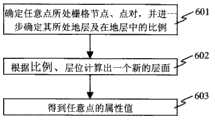
请参阅图6所示,为本发明求取三维地质模型中任意一点属性值的流程图;该流程包括如下步骤:Please refer to shown in Fig. 6, for the present invention seeks the flow chart of arbitrary point attribute value in three-dimensional geological model; This flow process comprises the following steps:
步骤601,根据任意点的XYZ坐标确定任意点处于哪一个栅格节点,哪一个点对之间,并进一步确定任意点处于哪一个地层以及在地层中的比例;
步骤602,根据所述比例和所处层位计算出一个新的层面;及
步骤603,求取测井曲线轨迹与该新层面的交点,根据所述交点的属性值通过插值得到所述任意点的属性值。
请参阅图7所示,为本发明的接口数据转换装置示意图。该接口数据转换装置70包括三维建模处理模块71、地震反演处理模块72,三维建模处理模块71又包括接口数据转换模块711、接口数据输出模块712;其中接口数据转换模块711用于生成三维地质模型的增强栅格格式数据文件,接口数据输出模块712用于输出三维地质模型的增强栅格格式数据文件;地震反演处理模块72用于读入增强栅格格式数据文件,并根据增强栅格格式数据文件进行地震反演运算。Please refer to FIG. 7 , which is a schematic diagram of the interface data conversion device of the present invention. The interface data conversion device 70 includes a three-dimensional modeling processing module 71 and a seismic inversion processing module 72, and the three-dimensional modeling processing module 71 includes an interface data conversion module 711 and an interface data output module 712; wherein the interface data conversion module 711 is used to generate The enhanced grid format data file of the 3D geological model, the interface data output module 712 is used to output the enhanced grid format data file of the 3D geological model; the seismic inversion processing module 72 is used to read the enhanced grid format data file, and according to the enhanced Raster format data files for seismic inversion operations.
本发明的增强栅格格式能够十分准确描述含有逆断层的三维地质模型,并在含有逆断层的三维地质模型中任意添加一个层。The enhanced grid format of the invention can very accurately describe the three-dimensional geological model containing reverse faults, and arbitrarily add a layer in the three-dimensional geological model containing reverse faults.
本发明提出了一种接口数据转换方法,实现了一个简单、方便交流的三维建模处理模块(软件)与地震反演处理模块(软件)之间数据的转换。所涉及的增强栅格格式包含了三维地质模型的必要的结构信息,离散的数据结构又与地震反演处理模块的数据格式相适应,该格式能够以简单的结构描述复杂的三维地质模型,是一种简单、离散又可以准确地表达三维地质模型拓扑结构的数据格式;通过这一增强栅格格式的桥梁作用,可以使地质三维建模处理模块和地震反演处理模块非常好的结合起来,方便地震反演处理模块使用。The invention proposes an interface data conversion method, which realizes a simple and convenient data conversion between the three-dimensional modeling processing module (software) and the seismic inversion processing module (software). The enhanced grid format involved contains the necessary structural information of the 3D geological model, and the discrete data structure is compatible with the data format of the seismic inversion processing module. This format can describe the complex 3D geological model with a simple structure, which is A data format that is simple, discrete and can accurately express the topological structure of the 3D geological model; through the bridge function of this enhanced grid format, the geological 3D modeling processing module and the seismic inversion processing module can be combined very well, It is convenient to use the seismic inversion processing module.
当然,本发明还可有其他多种实施例,在不背离本发明精神及其实质的情况下,熟悉本领域的技术人员当可根据本发明作出各种相应的改变和变形,但这些相应的改变和变形都应属于本发明所附的权利要求的保护范围。Of course, the present invention can also have other various embodiments, and those skilled in the art can make various corresponding changes and deformations according to the present invention without departing from the spirit and essence of the present invention, but these corresponding Changes and deformations should belong to the scope of protection of the appended claims of the present invention.
Claims (11)
Priority Applications (1)
| Application Number | Priority Date | Filing Date | Title |
|---|---|---|---|
| CN2006100114915ACN101038677B (en) | 2006-03-14 | 2006-03-14 | Interface data conversion method and device thereof |
Applications Claiming Priority (1)
| Application Number | Priority Date | Filing Date | Title |
|---|---|---|---|
| CN2006100114915ACN101038677B (en) | 2006-03-14 | 2006-03-14 | Interface data conversion method and device thereof |
Publications (2)
| Publication Number | Publication Date |
|---|---|
| CN101038677A CN101038677A (en) | 2007-09-19 |
| CN101038677Btrue CN101038677B (en) | 2011-09-21 |
Family
ID=38889559
Family Applications (1)
| Application Number | Title | Priority Date | Filing Date |
|---|---|---|---|
| CN2006100114915AActiveCN101038677B (en) | 2006-03-14 | 2006-03-14 | Interface data conversion method and device thereof |
Country Status (1)
| Country | Link |
|---|---|
| CN (1) | CN101038677B (en) |
Families Citing this family (2)
| Publication number | Priority date | Publication date | Assignee | Title |
|---|---|---|---|---|
| CN101303414B (en)* | 2008-05-22 | 2011-03-30 | 北京航空航天大学 | A Level Set-Based Method for Generating Strata and Geological Bodies |
| CN117392335B (en)* | 2023-09-26 | 2024-08-20 | 深圳市地质环境研究院有限公司 | Conversion method from three-dimensional surface element geologic model to three-dimensional surface element geologic model |
Citations (5)
| Publication number | Priority date | Publication date | Assignee | Title |
|---|---|---|---|---|
| CN1316722A (en)* | 2000-04-03 | 2001-10-10 | 上海大唐移动通信设备有限公司 | Method for topographic contour line conversion |
| CN1321249A (en)* | 1998-09-02 | 2001-11-07 | 菲利浦石油公司 | Automated seismic fault detection and picking |
| US20020013687A1 (en)* | 2000-03-27 | 2002-01-31 | Ortoleva Peter J. | Methods and systems for simulation-enhanced fracture detections in sedimentary basins |
| US20020120429A1 (en)* | 2000-12-08 | 2002-08-29 | Peter Ortoleva | Methods for modeling multi-dimensional domains using information theory to resolve gaps in data and in theories |
| WO2005076226A1 (en)* | 2004-02-03 | 2005-08-18 | British Telecommunications Public Limited Company | Animation techniques using quaternions |
- 2006
- 2006-03-14CNCN2006100114915Apatent/CN101038677B/enactiveActive
Patent Citations (5)
| Publication number | Priority date | Publication date | Assignee | Title |
|---|---|---|---|---|
| CN1321249A (en)* | 1998-09-02 | 2001-11-07 | 菲利浦石油公司 | Automated seismic fault detection and picking |
| US20020013687A1 (en)* | 2000-03-27 | 2002-01-31 | Ortoleva Peter J. | Methods and systems for simulation-enhanced fracture detections in sedimentary basins |
| CN1316722A (en)* | 2000-04-03 | 2001-10-10 | 上海大唐移动通信设备有限公司 | Method for topographic contour line conversion |
| US20020120429A1 (en)* | 2000-12-08 | 2002-08-29 | Peter Ortoleva | Methods for modeling multi-dimensional domains using information theory to resolve gaps in data and in theories |
| WO2005076226A1 (en)* | 2004-02-03 | 2005-08-18 | British Telecommunications Public Limited Company | Animation techniques using quaternions |
Non-Patent Citations (4)
| Title |
|---|
| 陈立潮.基于栅格的GIS三维空间数据模型.计算机工程30 8.2004,30(8),4-6. |
| 陈立潮.基于栅格的GIS三维空间数据模型.计算机工程30 8.2004,30(8),4-6.* |
| 龚健雅.矢量与栅格集成的三维数据模型.武汉测绘科技大学学报22 1.1997,22(1),7-15. |
| 龚健雅.矢量与栅格集成的三维数据模型.武汉测绘科技大学学报22 1.1997,22(1),7-15.* |
Also Published As
| Publication number | Publication date |
|---|---|
| CN101038677A (en) | 2007-09-19 |
Similar Documents
| Publication | Publication Date | Title |
|---|---|---|
| CN104574511B (en) | A kind of quick progressive three-dimensional geological modeling method | |
| CN107562833B (en) | Contour-based 3D Discrete Element Numerical Modeling Method for Complex Terrain | |
| CN102495427B (en) | Interface perception ray tracing method based on implicit model expression | |
| CN110163965B (en) | A Solid Three-Dimensional Model Construction Method of Monocline Structural Geomorphology | |
| CN102819039B (en) | Interval velocity model building method under complicated geological conditions | |
| KR102496592B1 (en) | System and method for managing earthwork data, and a recording medium having computer readable program for executing the method | |
| CN106023313A (en) | 3D geologic digital reconnaissance report generating method | |
| CN107464287B (en) | Surface reconstruction method based on multi-objective optimization | |
| CN107886573B (en) | A three-dimensional finite element mesh generation method for slopes under complex geological conditions | |
| CN110197013B (en) | Riverbed bedrock surface modeling method based on Morphing | |
| CN108256218A (en) | A kind of subterranean communication tunnel fine modeling method based on actual measurement stringcourse data | |
| CN114549774A (en) | A 3D stratigraphic modeling method based on borehole data | |
| CN109658512A (en) | The three-dimensional more volume modeling methods of shallow seismic profile | |
| CN109063324B (en) | Finite Element In-Situ Stress Simulation Technology Method Based on Corner Grid | |
| CN112150582B (en) | An Approximate Expression Method of Geological Profiles for Multimodal Data | |
| CN101694726B (en) | Fusing and drawing method based on multi-source terrain data | |
| CN118608705A (en) | A method for constructing a transparent three-dimensional geological model based on virtual borehole completion | |
| CN111951394B (en) | Method and device for constructing three-dimensional model of fault structural unit based on geological map | |
| CN117351165A (en) | A construction and calculation method of three-dimensional stratigraphic model based on ArcGIS | |
| CN101038677B (en) | Interface data conversion method and device thereof | |
| CN113190910B (en) | Slice analysis system and method based on BIM three-dimensional geological tunnel model | |
| CN103489217B (en) | Based on the modeling method of the buildings of column system | |
| CN117392335A (en) | Conversion method from three-dimensional surface element geologic model to three-dimensional surface element geologic model | |
| CN105719345A (en) | Coal rock mass geometric parameter measurement and three-dimensional reconstruction method | |
| CN113066180B (en) | Vault structure three-dimensional modeling method based on geological map |
Legal Events
| Date | Code | Title | Description |
|---|---|---|---|
| C06 | Publication | ||
| PB01 | Publication | ||
| C10 | Entry into substantive examination | ||
| SE01 | Entry into force of request for substantive examination | ||
| C53 | Correction of patent for invention or patent application | ||
| CB03 | Change of inventor or designer information | Inventor after:Meng Xianhai Inventor after:Yang Qin Inventor after:Li Jigang Inventor before:Yang Qin | |
| COR | Change of bibliographic data | Free format text:CORRECT: INVENTOR; FROM: YANG QIN TO: MENG XIANHAI YANG QIN LI JIGANG | |
| C14 | Grant of patent or utility model | ||
| GR01 | Patent grant | ||
| TR01 | Transfer of patent right | Effective date of registration:20170602 Address after:100088 Beijing City, Haidian District Zhichun Road No. 6 (Jinqiu International Building) A block, room 1501 Patentee after:Beijing grid world software technology Limited by Share Ltd Address before:100083 Haidian District, Xueyuan Road, No. 37, Patentee before:Beihang University | |
| TR01 | Transfer of patent right |