CN101038401A - Backlight module - Google Patents
Backlight moduleDownload PDFInfo
- Publication number
- CN101038401A CN101038401ACN 200710107416CN200710107416ACN101038401ACN 101038401 ACN101038401 ACN 101038401ACN 200710107416CN200710107416CN 200710107416CN 200710107416 ACN200710107416 ACN 200710107416ACN 101038401 ACN101038401 ACN 101038401A
- Authority
- CN
- China
- Prior art keywords
- backlight module
- guide plate
- light
- light guide
- widened
- Prior art date
- Legal status (The legal status is an assumption and is not a legal conclusion. Google has not performed a legal analysis and makes no representation as to the accuracy of the status listed.)
- Granted
Links
- 238000009792diffusion processMethods0.000claimsabstractdescription13
- 239000000758substrateSubstances0.000claimsdescription13
- 239000012788optical filmSubstances0.000claimsdescription8
- 238000000034methodMethods0.000abstractdescription8
- 239000004973liquid crystal related substanceSubstances0.000description8
- 238000002347injectionMethods0.000description5
- 239000007924injectionSubstances0.000description5
- 238000005516engineering processMethods0.000description4
- 238000001746injection mouldingMethods0.000description4
- 230000004308accommodationEffects0.000description2
- 238000004519manufacturing processMethods0.000description2
- 239000000463materialSubstances0.000description2
- 230000003247decreasing effectEffects0.000description1
- 238000005530etchingMethods0.000description1
- 239000010408filmSubstances0.000description1
- 238000009434installationMethods0.000description1
- 238000012986modificationMethods0.000description1
- 230000004048modificationEffects0.000description1
- 229920001690polydopaminePolymers0.000description1
- 238000007639printingMethods0.000description1
- 230000005855radiationEffects0.000description1
Images


Landscapes
- Planar Illumination Modules (AREA)
- Light Guides In General And Applications Therefor (AREA)
Abstract
Description
Translated fromChinese技术领域technical field
本发明有关于一种背光模组,尤指一种具有自入光面向另一侧面厚度渐增的导光板的背光模组。The invention relates to a backlight module, in particular to a backlight module with a light guide plate whose thickness gradually increases from the light incident surface to the other side.
背景技术Background technique
随着科技日新月异,各种智能型信息产品已经充斥于现代人的生活中,液晶显示装置等平面显示器模组在信息产品中扮演了相当重要的角色。由于液晶显示装置具有外型轻薄、耗电量少以及无辐射污染等特性,因此已被广泛地应用在笔记型计算机(notebook)、个人数字助理(personal digitalassistant,PDA)及手机等携带式信息产品上。With the rapid development of science and technology, various intelligent information products have filled the lives of modern people, and flat panel display modules such as liquid crystal display devices have played a very important role in information products. Liquid crystal display devices have been widely used in portable information products such as notebook computers (notebooks), personal digital assistants (personal digital assistants, PDAs) and mobile phones due to their thin and light appearance, low power consumption, and no radiation pollution. superior.
一般液晶显示装置皆包括一背光模组,以提供液晶显示面板背光源。请参考图1所示,图1为传统一背光模组10的剖面示意图。传统背光模组10包括一光源12、一导光板14、一反射片22设于导光板14下方、一外壳16、多片光学膜片18以及一印刷电路板(printed circuit board,PCB)20设于光源12下方。其中,印刷电路板20用来将电流或控制讯号传送给光源12。光源出光面12a面对导光板14的入光面14a而紧邻设置,且光源出光面12a的高度约略等同于导光板14的入光面14a的高度,使得由光源12所射出的光线可直接经由入光面14a射入导光板14中,并避免漏光。导光板14为一厚度均匀的平板,当光线射入导光板14后,光线会扩散而经由出光面14b射出,然后再经过光学膜片18而进入液晶显示面板(图中未示)中。A general liquid crystal display device includes a backlight module to provide a backlight source for the liquid crystal display panel. Please refer to FIG. 1 , which is a schematic cross-sectional view of a
由图1可知,由于印刷电路板20具有一定的厚度,且必须设置于光源12下方,导致光源12部分的厚度会较厚于整面平坦的导光板14,因此用来固定背光模组10所有组件的外壳16底部通常必须依照光源12一侧的厚度,制作出具有较深的容纳空间来放置光源12与印刷电路板20,而用来放置导光板14的部分则具有较浅的容纳空间。所以,外壳16通常具有一转折部分24,在制作上较为复杂。由上述可知,传统背光模组10中用于容置光源12的一侧会较厚于容置导光板14的另一侧,例如两者厚度差可能为约0.2毫米(公厘)至0.3毫米,对于讲求轻便的携带式信息产品来说,此种厚度差异已足以影响产品结构的设计。因此,传统背光模组10的结构设计仍须不断改良,以符合其应用产品的需求。It can be seen from FIG. 1 that since the printed
再者,由于传统导光板14多以射出成型技术来制作,而现行携带式产品中液晶显示装置的导光板14厚度约0.8毫米(公厘),其射出制程已达现行技术的极限,而且射出良率会随着导光板14的厚度减小而降低,因此如何改良导光板14的厚度要求,以配合现行射出技术而制作出良率高的导光板14,仍为业界需要解决的问题。Furthermore, because the traditional
发明内容Contents of the invention
本发明的目的在于提供一种具有自入光面向另一侧面厚度渐增的导光板的背光模组。The object of the present invention is to provide a backlight module with a light guide plate whose thickness increases gradually from the light incident surface to the other side.
本发明提供一种背光模组,其包括一导光板以及一光源设于导光板的一侧,使得光源所产生的光线可进入导光板中,导光板包括一顶面、一底面相对于顶面而倾斜设置且不平行于顶面、一入光面设于顶面与底面之间、一大于入光面面积的加宽面(widened edge plane),其中,加宽面相对于入光面而设于顶面与底面之间,而入光面更面对于光源,使光源所产生的光线可进入导光板中。所述背光模组还可进一步包括设置于导光板的底面的内面一扩散图案。The invention provides a backlight module, which includes a light guide plate and a light source arranged on one side of the light guide plate, so that the light generated by the light source can enter the light guide plate. The light guide plate includes a top surface and a bottom surface opposite to the top surface. And inclined and not parallel to the top surface, a light incident surface is set between the top surface and the bottom surface, and a widened edge plane (widened edge plane) is larger than the area of the light incident surface, wherein the widened edge plane is set relative to the light incident surface It is between the top surface and the bottom surface, and the light incident surface faces the light source so that the light generated by the light source can enter the light guide plate. The backlight module may further include a diffusion pattern disposed on the inner surface of the bottom surface of the light guide plate.
本发明还提供了一种背光模组,其包括一光源以及一导光板,所述导光板具有一第一面以及一第二面,其中该第一面面对于该光源,该第二面则相对于该第一面,且该第二面的高度大于该第一面的高度。The present invention also provides a backlight module, which includes a light source and a light guide plate, the light guide plate has a first surface and a second surface, wherein the first surface faces the light source, and the second surface Relative to the first surface, the height of the second surface is greater than the height of the first surface.
由于本发明的导光板具有不均匀的厚度,使得加宽面大于入光面面积,因此在导光板射出制程时可由加宽面一侧进行射出,以提升导光板的制程良率。Due to the non-uniform thickness of the light guide plate of the present invention, the widened surface is larger than the area of the light incident surface, so the light guide plate can be emitted from the side of the widened surface during the injection process to improve the process yield of the light guide plate.
附图说明Description of drawings
图1为传统背光模组的剖面示意图。FIG. 1 is a schematic cross-sectional view of a conventional backlight module.
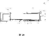
图2a、图2b为本发明背光模组的第一实施例的剖面示意图。2a and 2b are schematic cross-sectional views of the first embodiment of the backlight module of the present invention.
图3为本发明背光模组的第二实施例的剖面示意图。FIG. 3 is a schematic cross-sectional view of a second embodiment of the backlight module of the present invention.
10 背光模组 12 光源10
12a 出光面 14 导光板12a Light-
14a 入光面 14b 出光面14a Light-
16 外壳 18 光学膜片16
20 印刷电路板 22 反射片20 Printed
24 转折部分 50 背光模组24 Turning
52 光源 54 导光板52
56 外壳 58 光学膜片56 Shell Housing 58 Optical Film
60 电路基板 62 反射片60
64 光源出光面 66 入光面64 Light-emitting surface of the
68 加宽面 70 顶面68 widened
72 底面 74 扩散图案结构72
76 固定底面 78 扩散图案76 Fixed
具体实施方式Detailed ways
请参考图2a所示,图2a为本发明背光模组的第一实施例的剖面示意图。本发明背光模组50可应用于一液晶显示装置或其它需要背光源的装置中。背光模组50包括一导光板54、一光源52设于导光板54的入光面66侧、一用来容纳光源52与导光板54的外壳56、一电路基板60设于光源52下方,以及复数片光学膜片58设于导光板54上方。其中,光源52包括至少一发光二极管或其它合适的发光组件,而电路基板60较佳为一印刷电路板。由于电路基板60具有一定的厚度,会造成背光模组50两侧厚度不平均,因此本发明提供具有楔形结构的导光板54,其结构详述如下。Please refer to FIG. 2a, which is a schematic cross-sectional view of the first embodiment of the backlight module of the present invention. The
导光板54包括一顶面70、一相对于顶面70的底面72、一入光面66用来接收光源52所产生的光线且位于顶面70与底面72之间,以及一加宽面68位于顶面70与底面72之间且相对于入光面66。由图2a可知,底面72不平行于顶面70,而且导光板54的厚度由入光面66向加宽面68方向加厚,使得加宽面68的面积大于入光面66的面积,而加宽面68的垂直高度H也大于入光面66的垂直高度h,例如高度H大于高度h约0.1毫米至2毫米。因此,导光板54大致形成为楔形板的形状,且在加宽面68侧的厚度大于入光面66侧的厚度。此外,根据本发明的较佳实施例,导光板54另包括一扩散图案78设置于或形成于底面72的内面,用来改变导光板54内的光线行进路线。当光线由光源52的出光面64射出后,会由导光板54的入光面66射入导光板54,经由扩散图案78改变行进路线而分布整面导光板54,再由顶面70射出,经过顶面70上方的光学膜片58而提供光线给液晶显示面板(图中未示)。请参考图2b所示,在图2b中示出了本发明的另一种扩散图案结构74,其中该扩散图案结构74例如可以是一膜片,利用粘贴或以其他方式设置于导光板54的底面。The
在本实施例中,背光模组50另包括一反射片62设于导光板54的底面72下方,因此从底面72射出的光线会被反射片62反射回导光板54中,以提高光线利用率。由图2a、图2b可知,由于导光板54在远离光源52一侧的厚度较厚,补足了光源52侧因电路基板56而增加的厚度,因此电路基板60以及加宽面68下方的反射片62可刚好设置于外壳56的固定底面76上,使得固定底面76可平行于顶面70。In this embodiment, the
根据本发明背光模组50的设计,由于导光板54的加宽面68面积较大,因此在以射出成型方式制作导光板54时,可由加宽面68一侧进行射出,以提高射出良率,避免现有技术中因为导光板过薄而造成导光板制作困难的问题。According to the design of the
请参考图3,图3为本发明背光模组的第二实施例的剖面示意图。为简化说明,图3的各组件沿用图2的组件符号。在本实施例中,外壳56本身采用具有反射光线功能的材料制成,例如为白色亮面塑料材料等,以节省背光模组50的整体空间。因此,加宽面68的高度约略等于入光面66的高度与电路基板60厚度的总和,且电路基板60与加宽面68的底边皆约略设置于外壳56的固定底面76上。值得注意的是,由于本实施例省略了一反射片的设置,因此加宽面68的高度H会较第一实施例更大,所以更能够提高导光板54的射出良率。再者,在本实施例中,导光板54的底面72的内面形成有扩散图案78,用来改善光线行进路线,其可以蚀刻或印刷等方式所形成。Please refer to FIG. 3 . FIG. 3 is a schematic cross-sectional view of a second embodiment of the backlight module of the present invention. To simplify the description, the components in FIG. 3 follow the component symbols in FIG. 2 . In this embodiment, the
再者,不论是本发明的第一实施例或第二实施例,皆可运用于现行传统背光模组中,只要采用厚度较薄的光源,并且配合本发明的楔形导光板,使接近光源侧的导光板厚度较薄,而远离光源侧的导光板厚度则维持不变,便可使整体背光模组的厚度降低。Furthermore, both the first embodiment and the second embodiment of the present invention can be applied to the current traditional backlight module, as long as the light source with a thinner thickness is used and the wedge-shaped light guide plate of the present invention is used to make the light source close to the light source side The thickness of the light guide plate is relatively thin, while the thickness of the light guide plate on the side away from the light source remains unchanged, so that the thickness of the overall backlight module can be reduced.
相较于现有技术,由于本发明在背光模组中使用楔形导光板,使得接近光源侧的导光板厚度较薄,且无现有技术中的转折部分,因此可以有效减小背光模组的整体厚度。此外,由于导光板在远离光源侧具有面积较大的加宽面设计,因此可以利用面积较大的加宽面进行射出成型制程以制作导光板,提高导光板的制程良率,能解决现行薄型导光板的制程瓶颈。Compared with the prior art, because the present invention uses a wedge-shaped light guide plate in the backlight module, the thickness of the light guide plate near the light source side is thinner, and there is no turning part in the prior art, so the backlight module can be effectively reduced. overall thickness. In addition, since the light guide plate has a larger widened surface design on the side away from the light source, it can use the larger widened surface to carry out the injection molding process to make the light guide plate, improve the process yield of the light guide plate, and solve the current thin The process bottleneck of the light guide plate.
以上所述仅为本发明的较佳实施例,凡依本发明申请专利范围所做的均等变化与修饰,皆应属本发明的涵盖范围。The above descriptions are only preferred embodiments of the present invention, and all equivalent changes and modifications made according to the scope of the patent application of the present invention shall fall within the scope of the present invention.
Claims (26)
Translated fromChinesePriority Applications (1)
| Application Number | Priority Date | Filing Date | Title |
|---|---|---|---|
| CNB2007101074163ACN100462815C (en) | 2007-05-11 | 2007-05-11 | Backlight module |
Applications Claiming Priority (1)
| Application Number | Priority Date | Filing Date | Title |
|---|---|---|---|
| CNB2007101074163ACN100462815C (en) | 2007-05-11 | 2007-05-11 | Backlight module |
Publications (2)
| Publication Number | Publication Date |
|---|---|
| CN101038401Atrue CN101038401A (en) | 2007-09-19 |
| CN100462815C CN100462815C (en) | 2009-02-18 |
Family
ID=38889403
Family Applications (1)
| Application Number | Title | Priority Date | Filing Date |
|---|---|---|---|
| CNB2007101074163AActiveCN100462815C (en) | 2007-05-11 | 2007-05-11 | Backlight module |
Country Status (1)
| Country | Link |
|---|---|
| CN (1) | CN100462815C (en) |
Cited By (14)
| Publication number | Priority date | Publication date | Assignee | Title |
|---|---|---|---|---|
| CN101988664A (en)* | 2010-11-04 | 2011-03-23 | 友达光电股份有限公司 | Side light type backlight module |
| CN102155676A (en)* | 2010-01-07 | 2011-08-17 | Lg伊诺特有限公司 | Backlight unit, and display apparatus thereof |
| CN102635809A (en)* | 2011-02-04 | 2012-08-15 | 微软公司 | Directional backlighting for display panels |
| CN103791323A (en)* | 2013-12-31 | 2014-05-14 | 东莞市亚星半导体有限公司 | Backlight module |
| CN104180241A (en)* | 2013-05-22 | 2014-12-03 | 扬升照明股份有限公司 | Backlight module |
| CN105258025A (en)* | 2015-08-17 | 2016-01-20 | 友达光电股份有限公司 | Backlight module |
| US9256089B2 (en) | 2012-06-15 | 2016-02-09 | Microsoft Technology Licensing, Llc | Object-detecting backlight unit |
| US9268373B2 (en) | 2012-03-02 | 2016-02-23 | Microsoft Technology Licensing, Llc | Flexible hinge spine |
| US9304949B2 (en) | 2012-03-02 | 2016-04-05 | Microsoft Technology Licensing, Llc | Sensing user input at display area edge |
| US9354748B2 (en) | 2012-02-13 | 2016-05-31 | Microsoft Technology Licensing, Llc | Optical stylus interaction |
| US9870066B2 (en) | 2012-03-02 | 2018-01-16 | Microsoft Technology Licensing, Llc | Method of manufacturing an input device |
| US10678743B2 (en) | 2012-05-14 | 2020-06-09 | Microsoft Technology Licensing, Llc | System and method for accessory device architecture that passes via intermediate processor a descriptor when processing in a low power state |
| CN113075816A (en)* | 2021-03-17 | 2021-07-06 | 武汉华星光电技术有限公司 | Backlight module and display device |
| WO2023184097A1 (en)* | 2022-03-28 | 2023-10-05 | 京东方科技集团股份有限公司 | Backlight module and display device |
Family Cites Families (2)
| Publication number | Priority date | Publication date | Assignee | Title |
|---|---|---|---|---|
| CN1183410C (en)* | 2002-01-22 | 2005-01-05 | 诠兴开发科技股份有限公司 | Improvement method of light-emitting diode area light source |
| JP2004171948A (en)* | 2002-11-20 | 2004-06-17 | Harison Toshiba Lighting Corp | Backlight device |
- 2007
- 2007-05-11CNCNB2007101074163Apatent/CN100462815C/enactiveActive
Cited By (25)
| Publication number | Priority date | Publication date | Assignee | Title |
|---|---|---|---|---|
| CN102155676B (en)* | 2010-01-07 | 2015-11-25 | Lg伊诺特有限公司 | Back light unit and display device thereof |
| CN102155676A (en)* | 2010-01-07 | 2011-08-17 | Lg伊诺特有限公司 | Backlight unit, and display apparatus thereof |
| CN101988664A (en)* | 2010-11-04 | 2011-03-23 | 友达光电股份有限公司 | Side light type backlight module |
| CN102635809A (en)* | 2011-02-04 | 2012-08-15 | 微软公司 | Directional backlighting for display panels |
| US9201185B2 (en) | 2011-02-04 | 2015-12-01 | Microsoft Technology Licensing, Llc | Directional backlighting for display panels |
| CN102635809B (en)* | 2011-02-04 | 2015-03-25 | 微软公司 | Directional backlighting for display panels |
| US9354748B2 (en) | 2012-02-13 | 2016-05-31 | Microsoft Technology Licensing, Llc | Optical stylus interaction |
| US9678542B2 (en) | 2012-03-02 | 2017-06-13 | Microsoft Technology Licensing, Llc | Multiple position input device cover |
| US9870066B2 (en) | 2012-03-02 | 2018-01-16 | Microsoft Technology Licensing, Llc | Method of manufacturing an input device |
| US10963087B2 (en) | 2012-03-02 | 2021-03-30 | Microsoft Technology Licensing, Llc | Pressure sensitive keys |
| US9268373B2 (en) | 2012-03-02 | 2016-02-23 | Microsoft Technology Licensing, Llc | Flexible hinge spine |
| US9304949B2 (en) | 2012-03-02 | 2016-04-05 | Microsoft Technology Licensing, Llc | Sensing user input at display area edge |
| US10013030B2 (en) | 2012-03-02 | 2018-07-03 | Microsoft Technology Licensing, Llc | Multiple position input device cover |
| US9904327B2 (en) | 2012-03-02 | 2018-02-27 | Microsoft Technology Licensing, Llc | Flexible hinge and removable attachment |
| US9619071B2 (en) | 2012-03-02 | 2017-04-11 | Microsoft Technology Licensing, Llc | Computing device and an apparatus having sensors configured for measuring spatial information indicative of a position of the computing devices |
| US10678743B2 (en) | 2012-05-14 | 2020-06-09 | Microsoft Technology Licensing, Llc | System and method for accessory device architecture that passes via intermediate processor a descriptor when processing in a low power state |
| US9256089B2 (en) | 2012-06-15 | 2016-02-09 | Microsoft Technology Licensing, Llc | Object-detecting backlight unit |
| US9383497B2 (en) | 2013-05-22 | 2016-07-05 | Young Lighting Technology Inc. | Backlight module |
| CN104180241A (en)* | 2013-05-22 | 2014-12-03 | 扬升照明股份有限公司 | Backlight module |
| CN103791323A (en)* | 2013-12-31 | 2014-05-14 | 东莞市亚星半导体有限公司 | Backlight module |
| CN105258025A (en)* | 2015-08-17 | 2016-01-20 | 友达光电股份有限公司 | Backlight module |
| CN105258025B (en)* | 2015-08-17 | 2017-12-22 | 友达光电股份有限公司 | Backlight module |
| CN113075816A (en)* | 2021-03-17 | 2021-07-06 | 武汉华星光电技术有限公司 | Backlight module and display device |
| WO2023184097A1 (en)* | 2022-03-28 | 2023-10-05 | 京东方科技集团股份有限公司 | Backlight module and display device |
| US12216307B2 (en) | 2022-03-28 | 2025-02-04 | Hefei Xinsheng Optoelectronics Co., Ltd. | Backlight module and display apparatus |
Also Published As
| Publication number | Publication date |
|---|---|
| CN100462815C (en) | 2009-02-18 |
Similar Documents
| Publication | Publication Date | Title |
|---|---|---|
| CN101038401A (en) | Backlight module | |
| CN100445827C (en) | Light guide plate and backlight module | |
| CN100370329C (en) | Light guide plate and backlight module | |
| CN100489620C (en) | Backlight assembly and display apparatus having the same | |
| CN101303429B (en) | Optical sheet, method of manufacturing the same and display apparatus having the same | |
| CN103591512B (en) | Backlight module and the liquid crystal display module with this backlight module | |
| US20140104885A1 (en) | Light guide plate, backlight module and display device | |
| CN101571264B (en) | LED backlight module | |
| CN1542989A (en) | LED device | |
| CN1737660A (en) | light guide plate | |
| CN101046579A (en) | Systems Containing Backlight Modules with Stacked Light Sources | |
| CN1908754A (en) | Straight down type back light component and liquid crystal display device | |
| CN101881402A (en) | A light emitting diode light source structure | |
| WO2012012988A1 (en) | Light guide plate and backlight module | |
| WO2016019596A1 (en) | Backlight module structure | |
| US20150362653A1 (en) | Backlight module | |
| CN1580892A (en) | Backlight assembly providing light in multiple directions and display device employing the same | |
| CN201222148Y (en) | Optical assembly of backlight module | |
| CN108267892A (en) | A kind of backlight module and display device | |
| US7604387B2 (en) | Backlight module | |
| CN1877416A (en) | Back light module | |
| CN104279527A (en) | Circuit board integrating backlight module and manufacturing method thereof | |
| CN101446701A (en) | Liquid crystal display device having a plurality of pixel electrodes | |
| CN1996122A (en) | Backlight module | |
| CN1553259A (en) | Backlight module |
Legal Events
| Date | Code | Title | Description |
|---|---|---|---|
| C06 | Publication | ||
| PB01 | Publication | ||
| C10 | Entry into substantive examination | ||
| SE01 | Entry into force of request for substantive examination | ||
| C14 | Grant of patent or utility model | ||
| GR01 | Patent grant |