CN101037962A - Powertrain control apparatus and method - Google Patents
Powertrain control apparatus and methodDownload PDFInfo
- Publication number
- CN101037962A CN101037962ACN200710086084.5ACN200710086084ACN101037962ACN 101037962 ACN101037962 ACN 101037962ACN 200710086084 ACN200710086084 ACN 200710086084ACN 101037962 ACN101037962 ACN 101037962A
- Authority
- CN
- China
- Prior art keywords
- temperature
- clutch
- lock
- engine
- firing chamber
- Prior art date
- Legal status (The legal status is an assumption and is not a legal conclusion. Google has not performed a legal analysis and makes no representation as to the accuracy of the status listed.)
- Granted
Links
Images


Classifications
- F—MECHANICAL ENGINEERING; LIGHTING; HEATING; WEAPONS; BLASTING
- F02—COMBUSTION ENGINES; HOT-GAS OR COMBUSTION-PRODUCT ENGINE PLANTS
- F02D—CONTROLLING COMBUSTION ENGINES
- F02D41/00—Electrical control of supply of combustible mixture or its constituents
- F02D41/02—Circuit arrangements for generating control signals
- F02D41/04—Introducing corrections for particular operating conditions
- F02D41/12—Introducing corrections for particular operating conditions for deceleration
- F02D41/123—Introducing corrections for particular operating conditions for deceleration the fuel injection being cut-off
- F02D41/126—Introducing corrections for particular operating conditions for deceleration the fuel injection being cut-off transitional corrections at the end of the cut-off period
- B—PERFORMING OPERATIONS; TRANSPORTING
- B60—VEHICLES IN GENERAL
- B60W—CONJOINT CONTROL OF VEHICLE SUB-UNITS OF DIFFERENT TYPE OR DIFFERENT FUNCTION; CONTROL SYSTEMS SPECIALLY ADAPTED FOR HYBRID VEHICLES; ROAD VEHICLE DRIVE CONTROL SYSTEMS FOR PURPOSES NOT RELATED TO THE CONTROL OF A PARTICULAR SUB-UNIT
- B60W10/00—Conjoint control of vehicle sub-units of different type or different function
- B60W10/02—Conjoint control of vehicle sub-units of different type or different function including control of driveline clutches
- B60W10/024—Conjoint control of vehicle sub-units of different type or different function including control of driveline clutches including control of torque converters
- B60W10/026—Conjoint control of vehicle sub-units of different type or different function including control of driveline clutches including control of torque converters of lock-up clutches
- B—PERFORMING OPERATIONS; TRANSPORTING
- B60—VEHICLES IN GENERAL
- B60W—CONJOINT CONTROL OF VEHICLE SUB-UNITS OF DIFFERENT TYPE OR DIFFERENT FUNCTION; CONTROL SYSTEMS SPECIALLY ADAPTED FOR HYBRID VEHICLES; ROAD VEHICLE DRIVE CONTROL SYSTEMS FOR PURPOSES NOT RELATED TO THE CONTROL OF A PARTICULAR SUB-UNIT
- B60W10/00—Conjoint control of vehicle sub-units of different type or different function
- B60W10/04—Conjoint control of vehicle sub-units of different type or different function including control of propulsion units
- B60W10/06—Conjoint control of vehicle sub-units of different type or different function including control of propulsion units including control of combustion engines
- B—PERFORMING OPERATIONS; TRANSPORTING
- B60—VEHICLES IN GENERAL
- B60W—CONJOINT CONTROL OF VEHICLE SUB-UNITS OF DIFFERENT TYPE OR DIFFERENT FUNCTION; CONTROL SYSTEMS SPECIALLY ADAPTED FOR HYBRID VEHICLES; ROAD VEHICLE DRIVE CONTROL SYSTEMS FOR PURPOSES NOT RELATED TO THE CONTROL OF A PARTICULAR SUB-UNIT
- B60W30/00—Purposes of road vehicle drive control systems not related to the control of a particular sub-unit, e.g. of systems using conjoint control of vehicle sub-units
- B60W30/18—Propelling the vehicle
- B60W30/18009—Propelling the vehicle related to particular drive situations
- B60W30/18072—Coasting
- F—MECHANICAL ENGINEERING; LIGHTING; HEATING; WEAPONS; BLASTING
- F02—COMBUSTION ENGINES; HOT-GAS OR COMBUSTION-PRODUCT ENGINE PLANTS
- F02D—CONTROLLING COMBUSTION ENGINES
- F02D35/00—Controlling engines, dependent on conditions exterior or interior to engines, not otherwise provided for
- F02D35/02—Controlling engines, dependent on conditions exterior or interior to engines, not otherwise provided for on interior conditions
- F02D35/025—Controlling engines, dependent on conditions exterior or interior to engines, not otherwise provided for on interior conditions by determining temperatures inside the cylinder, e.g. combustion temperatures
- F—MECHANICAL ENGINEERING; LIGHTING; HEATING; WEAPONS; BLASTING
- F02—COMBUSTION ENGINES; HOT-GAS OR COMBUSTION-PRODUCT ENGINE PLANTS
- F02D—CONTROLLING COMBUSTION ENGINES
- F02D41/00—Electrical control of supply of combustible mixture or its constituents
- F02D41/02—Circuit arrangements for generating control signals
- F02D41/021—Introducing corrections for particular conditions exterior to the engine
- F02D41/0215—Introducing corrections for particular conditions exterior to the engine in relation with elements of the transmission
- F02D41/022—Introducing corrections for particular conditions exterior to the engine in relation with elements of the transmission in relation with the clutch status
- F—MECHANICAL ENGINEERING; LIGHTING; HEATING; WEAPONS; BLASTING
- F16—ENGINEERING ELEMENTS AND UNITS; GENERAL MEASURES FOR PRODUCING AND MAINTAINING EFFECTIVE FUNCTIONING OF MACHINES OR INSTALLATIONS; THERMAL INSULATION IN GENERAL
- F16H—GEARING
- F16H61/00—Control functions within control units of change-speed- or reversing-gearings for conveying rotary motion ; Control of exclusively fluid gearing, friction gearing, gearings with endless flexible members or other particular types of gearing
- F16H61/14—Control of torque converter lock-up clutches
- F16H61/143—Control of torque converter lock-up clutches using electric control means
- B—PERFORMING OPERATIONS; TRANSPORTING
- B60—VEHICLES IN GENERAL
- B60W—CONJOINT CONTROL OF VEHICLE SUB-UNITS OF DIFFERENT TYPE OR DIFFERENT FUNCTION; CONTROL SYSTEMS SPECIALLY ADAPTED FOR HYBRID VEHICLES; ROAD VEHICLE DRIVE CONTROL SYSTEMS FOR PURPOSES NOT RELATED TO THE CONTROL OF A PARTICULAR SUB-UNIT
- B60W2510/00—Input parameters relating to a particular sub-units
- B60W2510/06—Combustion engines, Gas turbines
- B60W2510/0676—Engine temperature
Landscapes
- Engineering & Computer Science (AREA)
- Chemical & Material Sciences (AREA)
- Combustion & Propulsion (AREA)
- Mechanical Engineering (AREA)
- General Engineering & Computer Science (AREA)
- Transportation (AREA)
- Automation & Control Theory (AREA)
- Control Of Vehicle Engines Or Engines For Specific Uses (AREA)
- Control Of Fluid Gearings (AREA)
- Electrical Control Of Air Or Fuel Supplied To Internal-Combustion Engine (AREA)
Abstract
Translated fromChinese
Description
Translated fromChinese技术领域technical field
本发明涉及一种动力传动系控制装置及方法。更具体地,本发明涉及一种包括锁止离合器的动力传动系,该锁止离合器使发动机直接连接至自动变速器。The invention relates to a power transmission control device and method. More specifically, the present invention relates to a powertrain that includes a lock-up clutch that directly connects the engine to an automatic transmission.
背景技术Background technique
传统自动变速器通过诸如变矩器的流体联接装置连接至发动机。变矩器通过在变矩器中循环的流体(例如,油)向变速器传递驱动力。从而,变矩器输入轴的转速与变矩器输出轴的转速不同。这会降低传递驱动力的效率。因此,通常提供使变矩器的输入轴机械地连接至输出轴的锁止离合器。A conventional automatic transmission is connected to the engine through a fluid coupling such as a torque converter. The torque converter transmits driving force to the transmission through fluid (eg, oil) circulating in the torque converter. Consequently, the rotational speed of the torque converter input shaft differs from the rotational speed of the torque converter output shaft. This reduces the efficiency of transmitting the driving force. Therefore, a lock-up clutch is typically provided that mechanically connects the input shaft of the torque converter to the output shaft.
为了提高燃料效率,当车辆减速时在车速等于或高于预定速度的情况下,燃料供应被切断,即,燃料喷射停止。如果在燃料供应被切断的情况下车速降至预定速度,则燃料喷射恢复(即,燃料供应恢复)。在燃料供应恢复后,发动机转速升高。从而,如果在燃料喷射恢复时锁止离合器接合,则会产生冲击,并且会使驾驶性能恶化。因此,动力传动系被控制成在燃料供应恢复时锁止离合器分离。In order to improve fuel efficiency, fuel supply is cut off, that is, fuel injection is stopped, when a vehicle speed is equal to or higher than a predetermined speed when the vehicle is decelerated. If the vehicle speed drops to a predetermined speed with the fuel supply cut off, fuel injection is resumed (ie, fuel supply resumes). After the fuel supply is restored, the engine speed increases. Thus, if the lock-up clutch is engaged when the fuel injection is resumed, a shock is generated and drivability is deteriorated. Accordingly, the driveline is controlled such that the lockup clutch disengages when fuel supply resumes.
日本专利申请公报No.2004-137963(JP-A-2004-137963)记载了一种用于在减速时控制车辆的控制装置,该控制装置在使锁止离合器分离后恢复燃料喷射。在JP-A-2004-137963中记载的控制装置控制这样的车辆,其中当加速踏板的操作量为零以使车辆减速时锁止离合器被控制并且燃料供应被切断。所述控制装置包括车速检测部分、加速踏板操作量检测部分、初始值设定部分、分离延迟时间测量部分、车速改变部分、分离控制部分、分离确认部分和燃料供应控制部分。车速检测部分检测车速。加速踏板操作量检测部分检测加速踏板的操作量。初始值设定部分在假定分离延迟时间较长的基础上预先设定分离车速的初始值,在所述分离车速下锁止离合器分离。分离延迟时间是指输出分离锁止离合器的指令信号的时刻和锁止离合器实际分离的时刻之间的延迟时间。分离延迟时间测量部分在锁止离合器分离时测量分离延迟时间。车速改变部分基于所测量出的分离延迟时间降低所设定的分离车速。分离控制部分在加速踏板的操作量为零并且所检测出的车速低于或等于所设定的分离车速时输出分离锁止离合器的指令信号。分离确认部分确认锁止离合器是否分离。燃料供应控制部分在锁止离合器实际分离后恢复燃料供应。Japanese Patent Application Publication No. 2004-137963 (JP-A-2004-137963) describes a control device for controlling a vehicle at the time of deceleration that resumes fuel injection after disengaging the lock-up clutch. The control device described in JP-A-2004-137963 controls a vehicle in which the lock-up clutch is controlled and the fuel supply is cut off when the operation amount of the accelerator pedal is zero to decelerate the vehicle. The control device includes a vehicle speed detection section, an accelerator pedal operation amount detection section, an initial value setting section, a separation delay time measurement section, a vehicle speed change section, a separation control section, a separation confirmation section, and a fuel supply control section. The vehicle speed detection section detects the vehicle speed. The accelerator pedal operation amount detection section detects the operation amount of the accelerator pedal. The initial value setting section preliminarily sets an initial value of a disengagement vehicle speed at which the lockup clutch disengages, on the assumption that a disengagement delay time is long. The disengagement delay time refers to a delay time between the time when the command signal to disengage the lock-up clutch is output and the time when the lock-up clutch is actually disengaged. The disengagement delay time measuring section measures a disengagement delay time when the lock-up clutch is disengaged. The vehicle speed changing portion reduces the set disengagement vehicle speed based on the measured disengagement delay time. The disengagement control section outputs a command signal to disengage the lock-up clutch when the operation amount of the accelerator pedal is zero and the detected vehicle speed is lower than or equal to the set disengagement vehicle speed. The disengagement confirmation section confirms whether the lockup clutch is disengaged. The fuel supply control section resumes fuel supply after the lock-up clutch is actually disengaged.
所述控制装置在假定分离延迟时间较长的基础上设定分离车速的初始值,并且随着分离延迟时间的缩短而降低所设定的分离车速。当加速踏板的操作量为零时,这增大了锁止离合器接合的车速范围。当锁止离合器实际分离时,所述控制装置还停止燃料供应切断。从而,能够提高燃料效率,以避免发动机失速,并在燃料供应恢复时避免冲击,而不管分离延迟时间如何。The control means sets an initial value of the disengagement vehicle speed on the assumption that the disengagement delay time is long, and decreases the set disengagement vehicle speed as the disengagement delay time decreases. This increases the vehicle speed range in which the lockup clutch is engaged when the operation amount of the accelerator pedal is zero. The control device also stops fuel supply cut-off when the lock-up clutch is actually disengaged. Thus, it is possible to improve fuel efficiency to avoid engine stall and to avoid shock when fuel supply is restored regardless of the separation delay time.
即使分离锁止离合器所需的时间为常量,在燃料供应恢复后,发动机转速会在某些情况下快速上升,而在其它情况下不会快速上升。但是,JP-A-2004-137963仅把注意力集中在分离锁止离合器所需的时间上。没有考虑从燃料供应恢复时到发动机转速开始上升时的时间。因此,当如JP-A-2004-137963中所述在锁止离合器实际分离后燃料供应恢复时,如果在燃料供应恢复后发动机转速没有迅速上升,则发动机转速会下降,这会导致发动机失速。Even if the time required to disengage the lock-up clutch is constant, after fuel supply is restored, the engine speed will rise rapidly in some cases but not in others. However, JP-A-2004-137963 focuses only on the time required to disengage the lock-up clutch. The time from when the fuel supply is restored to when the engine speed starts to rise is not taken into account. Therefore, when the fuel supply is restored after the lock-up clutch is actually disengaged as described in JP-A-2004-137963, if the engine speed does not rise rapidly after the fuel supply is restored, the engine speed drops, which causes the engine to stall.
发明内容Contents of the invention
本发明提供一种动力传动系控制装置及方法,其在燃料供应恢复时抑制冲击,并抑制发动机失速。The present invention provides a powertrain control device and method that suppresses shock when fuel supply is restored and suppresses engine stall.
本发明的第一方面涉及一种动力传动系控制装置,所述动力传动系包括使燃料供应被切断的发动机直接连接至自动变速器的锁止离合器。所述控制装置包括输出单元、控制单元和设定单元。所述输出单元输出指令以使所述锁止离合器的接合压力从所述锁止离合器接合时的压力值降低到所述锁止离合器分离时的压力值。所述控制单元在从所述指令被输出起经过预定的延迟时间时恢复向所述发动机的燃料供应。所述设定单元设定所述延迟时间,使得当所述发动机的燃烧室的温度为第一温度时的所述延迟时间比当所述发动机的燃烧室的温度为高于所述第一温度的第二温度时的所述延迟时间短。A first aspect of the present invention relates to a power train control apparatus including a lock-up clutch that directly connects an engine whose fuel supply is cut off to an automatic transmission. The control device includes an output unit, a control unit and a setting unit. The output unit outputs a command to lower the engagement pressure of the lock-up clutch from a pressure value when the lock-up clutch is engaged to a pressure value when the lock-up clutch is disengaged. The control unit resumes fuel supply to the engine when a predetermined delay time elapses from when the command is output. The setting unit sets the delay time so that the delay time is longer when the temperature of the combustion chamber of the engine is a first temperature than when the temperature of the combustion chamber of the engine is higher than the first temperature The delay time at the second temperature is short.
根据本发明的第一方面,当输出单元输出指令时,锁止离合器从接合状态进入分离状态。但是,在锁止离合器完全分离的时刻和锁止离合器分离过程的开始时刻之间有延迟。从而,当指令输出后经过预定的延迟时间时,向发动机的燃料供应恢复。从燃料供应恢复时到发动机转速开始上升时的时间根据发动机燃烧室的温度而变化。当燃烧室的温度较低时,燃料的燃烧性较差。因此,到发动机转速开始上升时所经过的时间较长。当燃烧室的温度较高时,燃料的燃烧性较好。因此,到发动机转速开始上升时所经过的时间较短。这样,指令输出时刻和燃料供应恢复时刻之间的延迟时间被设定成,使得当发动机燃烧室的温度为第一温度时的延迟时间比当发动机燃烧室的温度为高于第一温度的第二温度时的延迟时间短。例如,延迟时间可以基于发动机冷却剂的温度或燃料供应被切断的时间段而设定。延迟时间设定成随着发动机冷却剂温度的降低而缩短。或者,延迟时间设定成随着燃料供应被切断的时间段的延长而缩短。这样,当发动机燃烧室的温度较低而到发动机转速开始上升所经过的时间较长时,发动机被控制成燃料供应较早地恢复。相反,当发动机燃烧室的温度较高而到发动机转速开始上升所经过的时间较短时,发动机被控制成燃料供应较晚地恢复。这减小了锁止离合器实际分离的时刻与发动机转速开始上升的时刻之间的偏差。结果,可以提供在燃料供应恢复时抑制冲击并且抑制发动机失速的动力传动系控制装置。According to the first aspect of the present invention, when the output unit outputs the command, the lock-up clutch enters the disengaged state from the engaged state. However, there is a delay between the moment of complete disengagement of the lockup clutch and the start of the lockup clutch disengagement process. Thus, when a predetermined delay time elapses after the command is output, the supply of fuel to the engine is resumed. The time from when the fuel supply is restored to when the engine speed starts to rise varies depending on the temperature of the engine combustion chamber. When the temperature of the combustion chamber is low, the fuel is less combustible. Therefore, the elapsed time until the engine speed starts to rise is longer. When the temperature of the combustion chamber is higher, the combustibility of the fuel is better. Therefore, the elapsed time until the engine speed starts to rise is shorter. In this way, the delay time between the command output timing and the fuel supply recovery timing is set such that the delay time is longer when the temperature of the engine combustion chamber is the first temperature than when the temperature of the engine combustion chamber is the first temperature higher than the first temperature. The delay time at the second temperature is short. For example, the delay time may be set based on the temperature of the engine coolant or the time period during which the fuel supply is cut off. The delay time is set to decrease as the engine coolant temperature decreases. Alternatively, the delay time is set to be shortened as the period during which the fuel supply is cut off increases. Thus, when the temperature of the combustion chamber of the engine is low and the time elapsed until the engine speed starts to rise is long, the engine is controlled so that the fuel supply is restored earlier. Conversely, when the temperature of the engine combustion chamber is high and the time elapsed until the engine speed starts to rise is short, the engine is controlled so that the fuel supply is restored later. This reduces the discrepancy between when the lockup clutch is actually disengaged and when the engine speed starts to rise. As a result, it is possible to provide a power train control device that suppresses shock and suppresses engine stall when fuel supply is restored.
除了基于发动机冷却剂温度确定燃烧室温度之外,根据本发明第二方面的动力传动系控制装置与根据本发明第一方面的控制装置类似。The power train control device according to the second aspect of the invention is similar to the control device according to the first aspect of the invention except that the combustion chamber temperature is determined based on the engine coolant temperature.
根据本发明的第二方面,使用发动机冷却剂温度确定燃烧室温度。燃烧室温度与发动机冷却剂温度有关。从而,延迟时间基于燃烧室的温度而设定,也就是说,延迟时间基于发动机转速开始上升的时刻而设定,而无需直接测量燃烧室的温度。According to a second aspect of the invention, the engine coolant temperature is used to determine the combustion chamber temperature. Combustion chamber temperature is related to engine coolant temperature. Thus, the delay time is set based on the temperature of the combustion chamber, that is, the delay time is set based on the timing at which the engine speed starts to rise without directly measuring the temperature of the combustion chamber.
除了设定单元随着冷却剂温度的降低而缩短延迟时间之外,根据本发明第三方面的动力传动系控制装置与根据本发明第二方面的控制装置类似。The power train control device according to the third aspect of the present invention is similar to the control device according to the second aspect of the present invention except that the setting unit shortens the delay time as the temperature of the coolant decreases.
根据本发明的第三方面,延迟时间设定成随着发动机冷却剂温度的降低而缩短。从而,当发动机燃烧室的温度较低且到发动机转速开始上升所经过的时间较长时,发动机被控制成燃料供应较早地恢复。相反,当发动机燃烧室的温度较高且到发动机转速开始上升所经过的时间较短时,发动机被控制成燃料供应较晚地恢复。这减小了锁止离合器实际分离的时刻与发动机转速开始上升的时刻之间的偏差。结果,可以提供在燃料供应恢复时抑制冲击并且抑制发动机失速的动力传动系控制装置。According to the third aspect of the invention, the delay time is set to be shortened as the temperature of the engine coolant decreases. Thus, when the temperature of the combustion chamber of the engine is low and the time elapsed until the engine speed starts to rise is long, the engine is controlled so that the fuel supply is restored earlier. Conversely, when the temperature of the engine combustion chamber is high and the time elapsed until the engine speed starts to rise is short, the engine is controlled so that the fuel supply is restored later. This reduces the discrepancy between when the lockup clutch is actually disengaged and when the engine speed starts to rise. As a result, it is possible to provide a power train control device that suppresses shock and suppresses engine stall when fuel supply is restored.
除了燃烧室的温度基于发动机中燃料供应被切断的时间段而确定之外,根据本发明第四方面的动力传动系控制装置与根据本发明第一方面的控制装置类似。The power train control device according to the fourth aspect of the present invention is similar to the control device according to the first aspect of the present invention, except that the temperature of the combustion chamber is determined based on the time period during which the fuel supply in the engine is cut off.
根据本发明的第四方面,使用发动机中燃料供应被切断的时间段确定燃烧室的温度。燃烧室的温度与燃料供应被切断(即,燃料喷射停止)的时间段有关。从而,延迟时间基于燃烧室的温度设定,也就是说,基于发动机转速开始上升的时刻而设定,而无需直接测量燃烧室的温度。According to the fourth aspect of the present invention, the temperature of the combustion chamber is determined using the time period during which the fuel supply in the engine is cut off. The temperature of the combustion chamber is related to the period of time that the fuel supply is cut off (ie, fuel injection ceases). Thus, the delay time is set based on the temperature of the combustion chamber, that is, the timing at which the engine speed starts to rise, without directly measuring the temperature of the combustion chamber.
除了设定单元随着燃料供应被切断的时间段的延长而缩短延迟时间之外,根据本发明第五方面的动力传动系控制装置与根据本发明第四方面的控制装置类似。The power train control device according to the fifth aspect of the present invention is similar to the control device according to the fourth aspect of the present invention except that the setting unit shortens the delay time as the period during which the fuel supply is cut off increases.
根据本发明的第五方面,延迟时间设定成随着燃料供应被切断的时间段的延长而缩短。从而,当发动机燃烧室的温度较低且到发动机转速开始上升所经过的时间较长时,发动机被控制成燃料供应较早地恢复。相反,当发动机燃烧室的温度较高且到发动机转速开始上升所经过的时间较短时,发动机被控制成燃料供应较晚地恢复。这减小了锁止离合器实际分离的时刻与发动机转速开始上升的时刻之间的偏差。结果,可以提供在燃料供应恢复时抑制冲击并且抑制发动机失速的动力传动系控制装置。According to the fifth aspect of the present invention, the delay time is set to be shortened as the period during which the fuel supply is cut off increases. Thus, when the temperature of the combustion chamber of the engine is low and the time elapsed until the engine speed starts to rise is long, the engine is controlled so that the fuel supply is restored earlier. Conversely, when the temperature of the engine combustion chamber is high and the time elapsed until the engine speed starts to rise is short, the engine is controlled so that the fuel supply is restored later. This reduces the discrepancy between when the lockup clutch is actually disengaged and when the engine speed starts to rise. As a result, it is possible to provide a power train control device that suppresses shock and suppresses engine stall when fuel supply is restored.
附图说明Description of drawings
从下面参考附图对优选实施例的说明,本发明的上述及其它目的、特征和优点将变得显而易见,附图中相似的附图标记用于表示相似的元件,其中:The above and other objects, features and advantages of the present invention will become apparent from the following description of preferred embodiments with reference to the accompanying drawings, in which like reference numerals are used to represent like elements, wherein:
图1是示出设有根据第一实施例的控制装置的车辆动力传动系的示意图;1 is a schematic diagram showing a power train of a vehicle provided with a control device according to a first embodiment;
图2是示出液压回路的图示,该液压回路调节供应给变矩器的液压以控制锁止离合器;2 is a diagram showing a hydraulic circuit that regulates hydraulic pressure supplied to a torque converter to control a lock-up clutch;
图3是示出由ECU执行的程序的控制结构的流程图,该ECU是根据第一实施例的控制装置;3 is a flowchart showing a control structure of a program executed by the ECU, which is the control device according to the first embodiment;
图4是示出发动机冷却剂温度和延迟时间T(FC)之间关系的图示;FIG. 4 is a graph showing the relationship between the engine coolant temperature and the delay time T(FC);
图5是示出发动机转速NE的变化的时间图;FIG. 5 is a time chart showing changes in the engine speed NE;
图6是示出由ECU执行的程序的控制结构的流程图,该ECU是根据第二实施例的控制装置;6 is a flowchart showing a control structure of a program executed by an ECU, which is a control device according to a second embodiment;
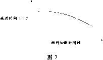
图7是示出燃料切断时间段和延迟时间T(FC)之间关系的图示。FIG. 7 is a graph showing the relationship between the fuel cut period and the delay time T(FC).
具体实施方式Detailed ways
下面将参考附图详细说明本发明的实施例。在下面的说明中,相同的部件由相同的附图标记表示,并具有相同的名称和相同的功能。因此,将省略冗余的说明。Embodiments of the present invention will be described in detail below with reference to the accompanying drawings. In the following description, the same components are denoted by the same reference numerals, and have the same names and the same functions. Therefore, redundant description will be omitted.
下面将参考图1说明设有根据本发明第一实施例的控制装置的车辆动力传动系。例如,当图1所示的ECU(电子控制单元)1000执行程序时,可以实现根据该实施例的控制装置。A vehicle power train provided with a control device according to a first embodiment of the present invention will be described below with reference to FIG. 1 . For example, the control apparatus according to this embodiment can be realized when ECU (Electronic Control Unit) 1000 shown in FIG. 1 executes the program.
如图1所示,车辆动力传动系包括发动机100、变矩器200、自动变速器300和ECU 1000。As shown in FIG. 1 , a vehicle power train includes an
发动机100的输出轴连接至变矩器200的输入轴。即,发动机100通过旋转轴连接至变矩器200。因此,由发动机转速传感器400检测到的发动机100的输出轴的转速NE(即,发动机转速NE)等于变矩器200的输入轴的转速(即,泵轮的转速)。An output shaft of
变矩器200包括:使输入轴直接连接至输出轴的锁止离合器210;位于输入轴侧的泵轮220;位于输出轴侧的涡轮230;以及包括单向离合器250并放大转矩的导轮240。The
变矩器200通过旋转轴连接至自动变速器300。涡轮转速传感器410检测变矩器200的输出轴的转速NT(即,涡轮转速NT)。输出轴转速传感器420检测自动变速器300的输出轴的转速NOUT。
自动变速器300可以是具有多个档位的变速器,该变速器包括行星齿轮单元。或者,自动变速器300可以是连续改变速比的无级变速器。The
ECU 1000接收来自发动机转速传感器400的指示发动机转速NE的信号、来自涡轮转速传感器410的指示涡轮转速NT的信号、来自输出轴转速传感器420的指示转速NOUT的信号、来自冷却剂温度传感器430的指示发动机100的冷却剂温度的信号、来自加速踏板操作量传感器440的指示加速踏板1200的操作量的信号和来自车速传感器450的指示车速的信号。The
ECU 1000基于这些信号控制发动机100、锁止离合器210和自动变速器300等。The
下面将参考图2说明液压回路500。液压回路500调节向变矩器200供应的液压以控制锁止离合器210。图2仅示出液压回路500的与本发明相关的部分。The
液压回路500包括油泵510、主调节阀520、次调节阀530、电磁调制阀540和锁止控制阀550。The
油泵510连接至发动机100的曲轴。当曲轴旋转时,油泵510抽取积存在油盘512中的自动变速器流体(ATF),从而产生液压。主调节阀520调节由油泵510产生的液压,从而产生管路压力。The
从主调节阀520排出的过量的变速器流体流入次调节阀530中。次调节阀530产生次级压力。Excess transmission fluid exhausted from
电磁调制阀540采用管路压力作为初始压力而产生电磁调制压力。电磁调制压力供应给占空比电磁阀560。The
锁止控制阀550选择性地将次级压力供应给变矩器200的接合侧油腔(即,泵轮220侧的油腔),或变矩器200的分离侧油腔(即,由锁止离合器210和变矩器盖260所限定的空间)。The lock-up
锁止控制阀550采用从占空比电磁阀560供应的液压作为先导压力而工作。当液压不从占空比电磁阀560向锁止控制阀550供应时,锁止控制阀550的阀芯处于图2中左侧(1)所示的位置中。The lock-up
在这种情况下,次级压力供应给变矩器200的分离侧油腔,且变矩器200的接合侧油腔中的液压供应给油冷却器(未示出)。结果,锁止离合器210从变矩器盖260上脱离,且锁止离合器210分离。In this case, the secondary pressure is supplied to the disengagement-side oil chamber of the
当液压从占空比电磁阀560供应给锁止控制阀550时,锁止控制阀550的阀芯处于图2中右侧(2)所示的位置中。When the hydraulic pressure is supplied from the
在这种情况下,次级压力供应给变矩器200的接合侧油腔,且液压从变矩器200的分离侧油腔泄压。结果,锁止离合器210被压向变矩器盖260,且锁止离合器210接合。In this case, the secondary pressure is supplied to the engagement-side oil chamber of the
锁止离合器210的接合压力(即,使锁止离合器210接合的压力)根据变矩器200中接合侧油腔和分离侧油腔之间的液压差而变化。The engagement pressure of the lock-up clutch 210 (ie, the pressure to engage the lock-up clutch 210 ) varies according to the hydraulic pressure difference between the engagement-side oil chamber and the disengagement-side oil chamber in the
接合侧油腔和分离侧油腔之间的液压差根据从占空比电磁阀560向锁止控制阀550供应的液压而变化。The hydraulic pressure difference between the engagement-side oil chamber and the disengagement-side oil chamber varies according to the hydraulic pressure supplied from the
占空比电磁阀560根据发送自ECU 1000的指令占空比值而输出压力。因此,锁止离合器210的接合压力由向占空比电磁阀560提供的指令占空比值控制。但是,控制锁止离合器210的接合压力的方法不限于该方法。The
下面将参考图3说明由ECU 1000所执行的程序的控制结构,ECU1000是根据该实施例的控制装置。The control structure of the program executed by
在步骤S100中,ECU 1000判断是否满足切断燃料供应的条件。例如,当车速高于阈值,且加速踏板的操作量为“0”(发动机100怠速)时,切断燃料供应的条件将得到满足。如果该条件满足(步骤S100中为“是”),则程序前进至步骤S110。如果该条件不满足(步骤S100中为“否”),则程序结束。在步骤S110中,ECU 1000切断燃料供应。In step S100,
在步骤S200中,ECU 1000判断是否满足恢复燃料供应的条件。例如,当车速低于或等于阈值时,恢复燃料供应的条件将得到满足。如果恢复燃料供应的条件满足(步骤S200中为“是”),则程序前进至步骤S300。如果恢复燃料供应的条件不满足(步骤S200中为“否”),则程序返回至S200。In step S200,
在步骤S300中,ECU 1000基于发动机100的冷却剂温度设定延迟时间T(FC)。如图4中的图所示,延迟时间T(FC)设定成随着冷却剂温度的降低而缩短。In step S300,
如图3所示,在步骤S400中,ECU 1000例如基于发动机转速NE和涡轮转速NT之间的差值是否小于或等于阈值而判断锁止离合器210是否接合。如果判定锁止离合器210接合(步骤S400中为“是”),则程序前进至步骤S410。如果判定锁止离合器210未接合(步骤S400中为“否”),则程序前进至步骤S600。As shown in FIG. 3, in step S400,
在步骤S410中,ECU 1000输出指令占空比值以将锁止离合器210的接合压力(即,接合侧油腔和分离侧油腔之间的液压差)从锁止离合器210接合时的第一液压减小到锁止离合器210分离时的第二液压。即,ECU1000输出指令以使锁止离合器210分离。从而,锁止离合器210的分离过程开始。In step S410, the
在步骤S500中,ECU 1000判断从将锁止离合器210的接合压力从第一液压减小到第二液压的输出指令占空比值被输出起是否经过了延迟时间T(FC)。如果经过了延迟时间T(FC)(步骤S500中为“是”),则程序前进至步骤S600。如果还没有经过延迟时间T(FC)(步骤S500中为“否”),则程序返回至步骤S500。In step S500,
在步骤S600中,ECU 1000停止燃料供应切断,即,恢复燃料喷射。In step S600,
下面将说明基于上述结构和流程图的ECU 1000的工作。ECU 1000是根据该实施例的控制装置。The operation of the
如果当车辆行驶时,例如当车辆减速时,满足切断燃料供应的条件(步骤S100中为“是”),则燃料供应被切断(S110)。然后,如果满足恢复燃料供应的条件(步骤S200中为“是”),则燃料供应最终恢复。If the condition for cutting off the fuel supply is satisfied when the vehicle is running, for example, when the vehicle is decelerating (YES in step S100), the fuel supply is cut off (S110). Then, if the condition for resuming fuel supply is satisfied (YES in step S200), fuel supply is finally resumed.
在燃料供应切断停止(即,燃料喷射恢复)后,发动机转速NE上升。如果当发动机转速NE上升时锁止离合器210接合,则产生冲击。因此,希望在锁止离合器210分离时恢复燃料供应。After the fuel supply cut-off is stopped (ie, the fuel injection is resumed), the engine speed NE rises. If the lock-up
在锁止离合器210的分离过程开始后,完全分离锁止离合器210需要时间。从而,一旦锁止离合器210的分离过程开始,当经过预定延迟时间T(FC)时,燃料供应切断停止。After the disengagement process of the lock-up clutch 210 starts, it takes time to completely disengage the lock-up
在燃料供应切断停止且燃料喷射恢复后,发动机转速NE不总是在相同时刻开始上升。例如,当发动机100的冷却剂温度较低时,发动机100的燃烧室温度较低,这时燃料的燃烧性较差。从而,与当发动机100的冷却剂温度较高时相比,当冷却剂的温度较低时,从燃料供应切断停止时到发动机转速NE开始上升时的时间较长。The engine speed NE does not always start to rise at the same timing after the fuel cut is stopped and the fuel injection is resumed. For example, when the coolant temperature of the
因此,当发动机100的冷却剂温度较低时,如果延迟时间T(FC)设定成与当冷却剂温度较高时相同的值,则发动机转速NE不上升,且锁止离合器210保持分离较长时间。从而,在发动机转速NE开始上升以前,发动机转速NE会大大下降。结果,发动机100会失速。Therefore, when the coolant temperature of the
因此,延迟时间T(FC)设定成随着发动机100的冷却剂温度的降低而缩短(S300)。如果锁止离合器210接合(步骤S400中为“是”),则指令占空比值被输出以将锁止离合器210的接合压力从第一液压降低到第二液压(S410)。Therefore, the delay time T(FC) is set to be shortened as the coolant temperature of the
如图5所示,在输出指令占空比值以分离锁止离合器210后,在经过延迟时间T(FC)后(步骤S500中为“是”),燃料供应切断停止(S600)。As shown in FIG. 5, after the command duty value is output to disengage the lock-up
延迟时间T(FC)设定成随着发动机100的冷却剂温度的降低而缩短。这减小了锁止离合器210分离的时刻与发动机转速NE开始上升的时刻之间的偏差。The delay time T(FC) is set to be shortened as the coolant temperature of the
如上所述,作为根据该实施例的控制装置的ECU将延迟时间T(FC)设定成使得该延迟时间T(FC)随着发动机冷却剂温度的降低而缩短。当输出指令占空比值以分离锁止离合器210后经过延迟时间T(FC)时,燃料供应切断停止,且燃料喷射恢复。这减小了锁止离合器分离的时刻与发动机转速NE开始上升的时刻之间的偏差。这样,当燃料供应恢复时可抑制冲击。此外,发动机不容易失速。As described above, the ECU as the control device according to this embodiment sets the delay time T(FC) such that the delay time T(FC) shortens as the engine coolant temperature decreases. When the delay time T(FC) elapses after the command duty value is output to disengage the lock-up
下面将说明本发明的第二实施例。第二实施例与第一实施例的不同之处在于延迟时间T(FC)基于燃料供应被切断的时间段(下文中称为“燃料切断时间段”)而不是发动机100的冷却剂温度来设定。该结构的其它部分与第一实施例中的相同。这些相同部分的功能与第一实施例中相同。从而,将省略其详细说明。Next, a second embodiment of the present invention will be described. The second embodiment differs from the first embodiment in that the delay time T(FC) is set based on the period during which the fuel supply is cut (hereinafter referred to as "fuel cut period") instead of the coolant temperature of the
下面将参考图6说明由ECU 1000执行的程序的控制结构,ECU 1000是根据该实施例的控制装置。与第一实施例中相同的过程用相同的步骤编号表示。从而,将省略对这些相同过程的详细说明。The control structure of the program executed by the
在步骤S700中,ECU 1000开始对燃料切断时间段计时。在步骤S710中,ECU 1000停止对燃料切断时间段计时。In step S700,
在步骤S800中,ECU基于燃料切断时间段设定延迟时间T(FC)。在图7所示的图中,延迟时间T(FC)设定成随着燃料切断时间段的延长而缩短。In step S800, the ECU sets a delay time T(FC) based on the fuel cut period. In the graph shown in FIG. 7, the delay time T(FC) is set to be shortened as the fuel cut period is extended.
下面将说明基于上述结构和流程图的ECU 1000的工作。ECU 1000是根据该实施例的控制装置。The operation of the
如上所述,发动机100的燃烧室温度随着发动机100的冷却剂温度的降低而下降。同样,燃烧室的温度随着燃料切断时间段的延长而下降。这样,当燃料供应被切断时(步骤S110),ECU 1000开始对燃料切断时间段计时(步骤S700)。当满足恢复燃料供应的条件时(步骤S200中为“是”),ECU 1000停止对燃料切断时间段计时(步骤S710)。As described above, the combustion chamber temperature of the
延迟时间T(FC)设定成随着经过的时间段的延长而缩短(S800)。这样,可以获得与在第一实施例中相同的效果。The delay time T(FC) is set to be shortened as the elapsed time period increases (S800). In this way, the same effects as in the first embodiment can be obtained.
延迟时间T(FC)也可以基于燃烧室的温度而设定。在这样的实施例中,可以在发动机100的燃烧室安装温度传感器以检测燃烧室温度。在这种情况下,延迟时间T(FC)基于由该温度传感器检测到的燃烧室温度而设定。因此,延迟时间T(FC)设定成随着燃烧室温度的降低而缩短。The delay time T(FC) can also be set based on the temperature of the combustion chamber. In such an embodiment, a temperature sensor may be installed in the combustion chamber of the
在本说明书中公开的本发明的实施例在所有方面都应认为是示例性而非限制性的。本发明的技术范围由权利要求限定,并因此试图包含处于权利要求的等效涵义和范围内的所有变型。The embodiments of the present invention disclosed in this specification are to be considered in all respects as illustrative and not restrictive. The technical scope of the present invention is defined by the claims, and all modifications within the meaning and range equivalent to the claims are therefore intended to be encompassed.
Claims (14)
Applications Claiming Priority (2)
| Application Number | Priority Date | Filing Date | Title |
|---|---|---|---|
| JP067516/2006 | 2006-03-13 | ||
| JP2006067516AJP2007239724A (en) | 2006-03-13 | 2006-03-13 | Powertrain control device |
Publications (2)
| Publication Number | Publication Date |
|---|---|
| CN101037962Atrue CN101037962A (en) | 2007-09-19 |
| CN100535418C CN100535418C (en) | 2009-09-02 |
Family
ID=38375063
Family Applications (1)
| Application Number | Title | Priority Date | Filing Date |
|---|---|---|---|
| CN200710086084.5AExpired - Fee RelatedCN100535418C (en) | 2006-03-13 | 2007-03-09 | Powertrain control apparatus and method |
Country Status (5)
| Country | Link |
|---|---|
| US (1) | US7699749B2 (en) |
| JP (1) | JP2007239724A (en) |
| CN (1) | CN100535418C (en) |
| DE (1) | DE102007000120B4 (en) |
| FR (1) | FR2898320B1 (en) |
Cited By (3)
| Publication number | Priority date | Publication date | Assignee | Title |
|---|---|---|---|---|
| CN101446343B (en)* | 2007-11-04 | 2013-06-19 | 通用汽车环球科技运作公司 | Method for controlling a powertrain system based upon energy storage device temperature |
| CN108662137A (en)* | 2018-07-23 | 2018-10-16 | 广西柳工机械股份有限公司 | Construction machinery gear box exports power cut control system and method |
| CN108799487A (en)* | 2017-05-01 | 2018-11-13 | 本田技研工业株式会社 | The hydraulic control device and hydraulic control method of speed changer |
Families Citing this family (11)
| Publication number | Priority date | Publication date | Assignee | Title |
|---|---|---|---|---|
| US8795135B2 (en)* | 2009-09-01 | 2014-08-05 | Ford Global Technologies, Llc | Method for controlling an engine during a restart |
| JP5901139B2 (en)* | 2011-05-10 | 2016-04-06 | ダイハツ工業株式会社 | Control method for internal combustion engine |
| US8708082B2 (en)* | 2011-08-17 | 2014-04-29 | GM Global Technology Operations LLC | Transmission oil delivery control system and method |
| JP5513570B2 (en)* | 2012-09-04 | 2014-06-04 | 本田技研工業株式会社 | Vehicle control device |
| ES2681890T3 (en)* | 2013-03-07 | 2018-09-17 | Fpt Industrial S.P.A. | Method to control an internal combustion engine and internal combustion engine |
| JP6094892B2 (en)* | 2013-10-16 | 2017-03-15 | 本田技研工業株式会社 | Vehicle control device |
| BR112017010701A2 (en)* | 2014-11-27 | 2017-12-26 | Nissan Motor | internal combustion engine control device and control method |
| US11519352B2 (en) | 2019-08-26 | 2022-12-06 | Kohler Co. | Spark ignited single cylinder engine derate for overheat |
| US11799342B2 (en) | 2020-02-20 | 2023-10-24 | Kohler Co. | Printed circuit board electrical machine |
| JP7563283B2 (en) | 2021-04-16 | 2024-10-08 | トヨタ自動車株式会社 | Vehicle control device |
| JP2023135931A (en) | 2022-03-16 | 2023-09-29 | 株式会社Subaru | clutch control system |
Family Cites Families (9)
| Publication number | Priority date | Publication date | Assignee | Title |
|---|---|---|---|---|
| JPH0725269A (en) | 1993-07-09 | 1995-01-27 | Mazda Motor Corp | Power plant control device of vehicle |
| US5626536A (en)* | 1994-07-19 | 1997-05-06 | Toyota Jidosha Kabushiki Kaisha | Lock-up clutch slip control apparatus and engine fuel-cut control apparatus for motor vehicle |
| JP2000257483A (en)* | 1999-03-03 | 2000-09-19 | Toyota Motor Corp | Fuel cut return control device |
| JP3562429B2 (en) | 2000-03-21 | 2004-09-08 | 日産自動車株式会社 | Hybrid vehicle control device |
| JP4066776B2 (en)* | 2002-10-17 | 2008-03-26 | 日産自動車株式会社 | Control device for vehicle deceleration |
| JP4321253B2 (en)* | 2003-12-18 | 2009-08-26 | 日産自動車株式会社 | Torque converter lockup control device |
| JP4337633B2 (en)* | 2004-05-24 | 2009-09-30 | 日産自動車株式会社 | Vehicle control device |
| JP4525938B2 (en)* | 2004-06-21 | 2010-08-18 | 三菱自動車工業株式会社 | Exhaust gas purification device for vehicle internal combustion engine |
| JP4240049B2 (en)* | 2006-04-11 | 2009-03-18 | トヨタ自動車株式会社 | Powertrain control device |
- 2006
- 2006-03-13JPJP2006067516Apatent/JP2007239724A/enactivePending
- 2007
- 2007-02-28DEDE102007000120.9Apatent/DE102007000120B4/ennot_activeExpired - Fee Related
- 2007-03-09CNCN200710086084.5Apatent/CN100535418C/ennot_activeExpired - Fee Related
- 2007-03-12USUS11/716,699patent/US7699749B2/ennot_activeExpired - Fee Related
- 2007-03-13FRFR0753794Apatent/FR2898320B1/ennot_activeExpired - Fee Related
Cited By (3)
| Publication number | Priority date | Publication date | Assignee | Title |
|---|---|---|---|---|
| CN101446343B (en)* | 2007-11-04 | 2013-06-19 | 通用汽车环球科技运作公司 | Method for controlling a powertrain system based upon energy storage device temperature |
| CN108799487A (en)* | 2017-05-01 | 2018-11-13 | 本田技研工业株式会社 | The hydraulic control device and hydraulic control method of speed changer |
| CN108662137A (en)* | 2018-07-23 | 2018-10-16 | 广西柳工机械股份有限公司 | Construction machinery gear box exports power cut control system and method |
Also Published As
| Publication number | Publication date |
|---|---|
| JP2007239724A (en) | 2007-09-20 |
| FR2898320B1 (en) | 2013-12-20 |
| FR2898320A1 (en) | 2007-09-14 |
| US20070213177A1 (en) | 2007-09-13 |
| DE102007000120B4 (en) | 2014-03-13 |
| CN100535418C (en) | 2009-09-02 |
| DE102007000120A1 (en) | 2007-09-20 |
| US7699749B2 (en) | 2010-04-20 |
Similar Documents
| Publication | Publication Date | Title |
|---|---|---|
| CN101037962A (en) | Powertrain control apparatus and method | |
| CN100580284C (en) | Power train control apparatus and method | |
| CN1282569C (en) | Start control device for vehicle | |
| CN1264712C (en) | Drivnig control device and method for vehicle | |
| CN1289840C (en) | Vehicle drive control device and control method thereof | |
| CN101040135A (en) | Automatic gear control device | |
| CN1304771C (en) | Shift control apparatus and shift control method for a vehicular automatic transmission | |
| CN1958364A (en) | Control device and control method for vehicle | |
| CN1453160A (en) | Vehicle drive controlling apparatus and method | |
| CN1711183A (en) | Speed change control method and device for mechanical gearbox | |
| CN1892076A (en) | Neutral control apparatus and method for a vehicle with an automatic transmission | |
| CN101772660B (en) | Control device and control method for vehicle | |
| CN101187422A (en) | vehicle control equipment | |
| CN1991213A (en) | Speed change control device and speed change control method for automatic transmission for vehicle | |
| CN1955517A (en) | Speed change control device and speed change control method for automatic transmission | |
| CN1292182C (en) | Shift control device and shift control method for vehicle automatic transmission | |
| CN1506597A (en) | Control device and method for automatic transmission | |
| CN1782350A (en) | Vehicle controller | |
| CN1616854A (en) | Power transmission device and hydraulic torque converter lock-up control method | |
| CN1576657A (en) | vehicle launch control equipment | |
| CN1769745A (en) | Torque converter lockup capacity control device | |
| US7510505B2 (en) | Powertrain and method of operation | |
| KR100949070B1 (en) | Automatic Transmission Control | |
| CN101688487B (en) | Control device and control method for vehicle | |
| CN102282350B (en) | Control device for vehicle |
Legal Events
| Date | Code | Title | Description |
|---|---|---|---|
| C06 | Publication | ||
| PB01 | Publication | ||
| C10 | Entry into substantive examination | ||
| SE01 | Entry into force of request for substantive examination | ||
| C14 | Grant of patent or utility model | ||
| GR01 | Patent grant | ||
| CF01 | Termination of patent right due to non-payment of annual fee | ||
| CF01 | Termination of patent right due to non-payment of annual fee | Granted publication date:20090902 Termination date:20160309 |