CN101035474B - Devices used to remove blood clots - Google Patents
Devices used to remove blood clotsDownload PDFInfo
- Publication number
- CN101035474B CN101035474BCN2005800335786ACN200580033578ACN101035474BCN 101035474 BCN101035474 BCN 101035474BCN 2005800335786 ACN2005800335786 ACN 2005800335786ACN 200580033578 ACN200580033578 ACN 200580033578ACN 101035474 BCN101035474 BCN 101035474B
- Authority
- CN
- China
- Prior art keywords
- support
- thrombus
- cage
- basket structure
- distal
- Prior art date
- Legal status (The legal status is an assumption and is not a legal conclusion. Google has not performed a legal analysis and makes no representation as to the accuracy of the status listed.)
- Expired - Fee Related
Links
Images


Classifications
- A—HUMAN NECESSITIES
- A61—MEDICAL OR VETERINARY SCIENCE; HYGIENE
- A61B—DIAGNOSIS; SURGERY; IDENTIFICATION
- A61B17/00—Surgical instruments, devices or methods
- A61B17/22—Implements for squeezing-off ulcers or the like on inner organs of the body; Implements for scraping-out cavities of body organs, e.g. bones; for invasive removal or destruction of calculus using mechanical vibrations; for removing obstructions in blood vessels, not otherwise provided for
- A61B17/221—Gripping devices in the form of loops or baskets for gripping calculi or similar types of obstructions
- A—HUMAN NECESSITIES
- A61—MEDICAL OR VETERINARY SCIENCE; HYGIENE
- A61B—DIAGNOSIS; SURGERY; IDENTIFICATION
- A61B10/00—Instruments for taking body samples for diagnostic purposes; Other methods or instruments for diagnosis, e.g. for vaccination diagnosis, sex determination or ovulation-period determination; Throat striking implements
- A61B10/02—Instruments for taking cell samples or for biopsy
- A61B2010/0216—Sampling brushes
- A—HUMAN NECESSITIES
- A61—MEDICAL OR VETERINARY SCIENCE; HYGIENE
- A61B—DIAGNOSIS; SURGERY; IDENTIFICATION
- A61B17/00—Surgical instruments, devices or methods
- A61B17/22—Implements for squeezing-off ulcers or the like on inner organs of the body; Implements for scraping-out cavities of body organs, e.g. bones; for invasive removal or destruction of calculus using mechanical vibrations; for removing obstructions in blood vessels, not otherwise provided for
- A61B2017/22001—Angioplasty, e.g. PCTA
- A—HUMAN NECESSITIES
- A61—MEDICAL OR VETERINARY SCIENCE; HYGIENE
- A61B—DIAGNOSIS; SURGERY; IDENTIFICATION
- A61B17/00—Surgical instruments, devices or methods
- A61B17/22—Implements for squeezing-off ulcers or the like on inner organs of the body; Implements for scraping-out cavities of body organs, e.g. bones; for invasive removal or destruction of calculus using mechanical vibrations; for removing obstructions in blood vessels, not otherwise provided for
- A61B17/22031—Gripping instruments, e.g. forceps, for removing or smashing calculi
- A61B2017/22034—Gripping instruments, e.g. forceps, for removing or smashing calculi for gripping the obstruction or the tissue part from inside
- A—HUMAN NECESSITIES
- A61—MEDICAL OR VETERINARY SCIENCE; HYGIENE
- A61B—DIAGNOSIS; SURGERY; IDENTIFICATION
- A61B17/00—Surgical instruments, devices or methods
- A61B17/22—Implements for squeezing-off ulcers or the like on inner organs of the body; Implements for scraping-out cavities of body organs, e.g. bones; for invasive removal or destruction of calculus using mechanical vibrations; for removing obstructions in blood vessels, not otherwise provided for
- A61B2017/22038—Implements for squeezing-off ulcers or the like on inner organs of the body; Implements for scraping-out cavities of body organs, e.g. bones; for invasive removal or destruction of calculus using mechanical vibrations; for removing obstructions in blood vessels, not otherwise provided for with a guide wire
- A61B2017/22042—Details of the tip of the guide wire
- A—HUMAN NECESSITIES
- A61—MEDICAL OR VETERINARY SCIENCE; HYGIENE
- A61B—DIAGNOSIS; SURGERY; IDENTIFICATION
- A61B17/00—Surgical instruments, devices or methods
- A61B17/22—Implements for squeezing-off ulcers or the like on inner organs of the body; Implements for scraping-out cavities of body organs, e.g. bones; for invasive removal or destruction of calculus using mechanical vibrations; for removing obstructions in blood vessels, not otherwise provided for
- A61B2017/22079—Implements for squeezing-off ulcers or the like on inner organs of the body; Implements for scraping-out cavities of body organs, e.g. bones; for invasive removal or destruction of calculus using mechanical vibrations; for removing obstructions in blood vessels, not otherwise provided for with suction of debris
- A—HUMAN NECESSITIES
- A61—MEDICAL OR VETERINARY SCIENCE; HYGIENE
- A61B—DIAGNOSIS; SURGERY; IDENTIFICATION
- A61B17/00—Surgical instruments, devices or methods
- A61B17/22—Implements for squeezing-off ulcers or the like on inner organs of the body; Implements for scraping-out cavities of body organs, e.g. bones; for invasive removal or destruction of calculus using mechanical vibrations; for removing obstructions in blood vessels, not otherwise provided for
- A61B17/221—Gripping devices in the form of loops or baskets for gripping calculi or similar types of obstructions
- A61B2017/2212—Gripping devices in the form of loops or baskets for gripping calculi or similar types of obstructions having a closed distal end, e.g. a loop
- A—HUMAN NECESSITIES
- A61—MEDICAL OR VETERINARY SCIENCE; HYGIENE
- A61B—DIAGNOSIS; SURGERY; IDENTIFICATION
- A61B90/00—Instruments, implements or accessories specially adapted for surgery or diagnosis and not covered by any of the groups A61B1/00 - A61B50/00, e.g. for luxation treatment or for protecting wound edges
- A61B90/39—Markers, e.g. radio-opaque or breast lesions markers
- A61B2090/397—Markers, e.g. radio-opaque or breast lesions markers electromagnetic other than visible, e.g. microwave
Landscapes
- Health & Medical Sciences (AREA)
- Surgery (AREA)
- Life Sciences & Earth Sciences (AREA)
- Heart & Thoracic Surgery (AREA)
- Molecular Biology (AREA)
- Vascular Medicine (AREA)
- Engineering & Computer Science (AREA)
- Biomedical Technology (AREA)
- Orthopedic Medicine & Surgery (AREA)
- Medical Informatics (AREA)
- Nuclear Medicine, Radiotherapy & Molecular Imaging (AREA)
- Animal Behavior & Ethology (AREA)
- General Health & Medical Sciences (AREA)
- Public Health (AREA)
- Veterinary Medicine (AREA)
- Surgical Instruments (AREA)
- Materials For Medical Uses (AREA)
Abstract
Description
Translated fromChinese技术领域technical field
本发明涉及一种用于借助一根导引丝从身体空腔和血管中取出异物和血栓的装置,该导引丝具有一个远端部件。该远端部件不可拆卸地与导引丝连接。 The invention relates to a device for removing foreign bodies and thrombi from body cavities and blood vessels by means of a guide wire having a distal end part. The distal part is non-detachably connected to the guide wire. the
本发明还涉及这种装置与一个笼部件的组合。 The invention also relates to the combination of such a device with a cage part. the
背景技术Background technique
一般由一个附着在血管中并完全或局部地阻塞该血管的血栓栓塞(以下简称血栓)也就是一个由血小板、纤维蛋白原、凝血因子等组成的粘滞弹性的血块引起一些血栓栓塞疾病,如心肌梗死、肺栓塞、外周血栓形成(periphere Thrombose)、器官栓塞等。在此器官动脉(Organarterien)的阻塞导致相关组织的供氧和营养中断。伴随功能丧失的功能代谢紊乱在短时间内导致伴随相关组织死亡(梗死)的组织代谢丧失。其中在人体器官中最多的是心脏和大脑。但是这种变化也经常发生在肢体动脉和肺动脉。静脉血栓形成和血栓栓塞的梗死经常在腿静脉和背静脉中出现。颅内窦的血栓栓塞阻塞病症由于脑组织的静脉排液的干扰可以导致严重的脑出血。 Generally, some thromboembolic diseases are caused by a thromboembolism (hereinafter referred to as thrombus) attached to a blood vessel and completely or partially blocking the blood vessel, that is, a viscoelastic blood clot composed of platelets, fibrinogen, coagulation factors, etc., such as Myocardial infarction, pulmonary embolism, peripheral thrombosis, organ embolism, etc. Blockage of the organ arteries results in an interruption of the oxygen and nutrition supply to the relevant tissues. Functional metabolic disturbances with loss of function result within a short period of time in loss of tissue metabolism with associated tissue death (infarction). Among the human organs, the heart and the brain are the most numerous. But this change also frequently occurs in the arteries of the limbs and the pulmonary arteries. Venous thrombotic and thromboembolic infarctions frequently occur in the leg and dorsal veins. Thromboembolic occlusive disorders of the intracranial sinuses can lead to severe cerebral hemorrhage due to disturbance of the venous drainage of the brain tissue. the
鉴于由血栓栓塞引起的病症的严重性和这些疾病的多发性,已知许多用于溶解或取出血栓的技术。 In view of the severity of the conditions caused by thromboembolism and the multiplicity of these diseases, many techniques are known for dissolving or removing the thrombus. the
例如已知通过血栓溶解剂如链激酶或尿激酶或通过抗凝血剂治疗这样的病人,这能够溶解血栓或抑制血栓生长。因为这种治疗方法大多是时间紧迫的,它们经常与手术相结合,它们用于机械地破碎或取出血栓或栓塞。 It is known, for example, to treat such patients with thrombolytic agents such as streptokinase or urokinase or with anticoagulants, which dissolve the thrombus or inhibit its growth. Because most of these treatments are time-critical, they are often combined with surgery, which is used to mechanically break up or remove the thrombus or embolism. the
除了外科手术以外,在现有技术中越来越多地使用内腔式或内管式导管导入的干涉治疗形式,因为这种治疗形式是更少侵入的。例如已知通过产生负压的抽吸导管或机械地通过配有捕获笼、螺旋、钩或类似部件的导管从患者身体中取出血栓,见US6245089B1、US5171233A1, Thomas E.Mayer等,Stroke 2002(9),2232。 In addition to surgery, endoluminal or endocannulated catheter-introduced interventional forms of treatment are increasingly being used in the prior art, since this form of treatment is less invasive. It is known, for example, to remove thrombi from a patient's body by means of a suction catheter generating negative pressure or mechanically through a catheter equipped with a capture cage, helix, hook or the like, see US6245089B1, US5171233A1, Thomas E.Mayer et al., Stroke 2002 (9 ), 2232. the
已知的内腔式装置的缺陷是,它们经常不能完全取出血栓,并且存在着释放血栓或其碎块并且在血流中继续引到更小口径血管的危险,这些更小口径血管更难达到和治疗。此外在现有技术中,已知的装置由于其尺寸和/或微小的柔韧性不足以适用于从特别小口径的或者旋绕的血管如大脑的血管中取出血栓。 A disadvantage of known endoluminal devices is that they often do not completely remove the thrombus and there is a risk of releasing the thrombus or its fragments and continuing in the bloodstream to smaller caliber vessels, which are more difficult to reach and treatment. Furthermore, known devices from the prior art are not suitable due to their size and/or low flexibility for removing thrombi from particularly small-caliber or convoluted blood vessels, such as those of the brain. the
由US2002/0049452已知一种用于取出血栓的具有一根导管的装置,在其远端部上安置由一种形状记忆材料制成的捕获臂,它们在压缩状态贴靠在导管上而在膨胀形态则径向从导管向外延伸。在通过体温引起占据膨胀形态以后,捕获臂能够钩住血栓并使血栓在将导管拉回到另一导管时从血管中一起拉出。这个装置的缺陷是,或者为了使捕获臂冷却到进入血流的转换温度以下,直到它们到达血流中,必须在一个能够实现这种冷却的二次导管中在血栓旁边操纵该装置;或者设有捕获臂的导管必须在其内部带有一个加热装置,它在到达血栓以后能够加热到转换温度。这些结构上的要求一方面是非常昂贵的继而也是易受干扰的而且由于其物理尺寸不能治疗特别小口径的血管。 Known from US 2002/0049452 is a device with a catheter for removing thrombus, on its distal end, capture arms made of a shape-memory material are arranged, which rest against the catheter in a compressed state The expanded configuration then extends radially outward from the catheter. After occupying the expanded configuration induced by body temperature, the capture arms are able to hook the thrombus and pull the thrombus out of the blood vessel with it when the catheter is pulled back to the other catheter. The disadvantage of this device is that, either in order to cool the capture arms below the transition temperature into the bloodstream until they reach the bloodstream, the device must be manipulated next to the thrombus in a secondary catheter that enables such cooling; or Catheters with capture arms must have an internal heating device that can be heated to the transition temperature after reaching the thrombus. These structural requirements are, on the one hand, very expensive, and also trouble-prone, and because of their physical size, blood vessels of particularly small diameter cannot be treated. the
发明内容Contents of the invention
因此鉴于与现有技术相关的缺陷,本发明的目的是,提供一个用于从身体空腔或血管中取出异物或血栓的装置,它减小了在取出血栓时的手术危险并且能够治疗特别小口径的血管。 Therefore, in view of the disadvantages associated with the prior art, it is an object of the present invention to provide a device for removing foreign bodies or thrombi from body cavities or blood vessels, which reduces the surgical risks during the removal of thrombi and which can treat particularly small caliber blood vessels. the
按照本发明这个目的通过上述形式的装置得以实现,其特征是,所述远端部件配备有一个基本正交的结构。该正交的结构优选由许多纤维/刷毛(Borsten)制成,它们可以单根或成束地设置。 This object is achieved according to the invention by means of a device of the above-mentioned form, characterized in that said distal part is provided with a substantially orthogonal structure. The orthogonal structure is preferably produced from a plurality of fibers/bristles, which can be arranged individually or in bundles. the
本发明基于发明人的成果,它们证明,使用这种简单设计的继而保持特别小体积的装置适合于从尤其非常小口径的血管中取出血栓。构成导引辅助装置的导引丝也能够在小口径和旋绕的血管段中实现良好的操作性并且使装置的总直径尤其是装置的不变化的直径保持较小(通过纤维限制的直径是变化的,如同它们是可弯曲的,继而也可以通过狭窄的血管)。纤维/刷毛适合于固定保持并稳定血栓,尤其是当它们由凝血酶 原材料(thrombogenen Materialien)制成或者配备有这种材料的时候。 The present invention is based on the results of the inventors, who demonstrated that a device with such a simple design, which is then kept particularly small in size, is suitable for removing thrombus from blood vessels of especially very small caliber. The guide wire constituting the guiding aid also enables good maneuverability in small-bore and convoluted vessel segments and keeps the overall diameter of the device, especially the constant diameter of the device, small (the diameter limited by the fibers is variable). , as they are bendable, which in turn can also pass through narrow blood vessels). The fibers/bristles are suitable for firmly holding and stabilizing thrombus, especially when they are made of or equipped with thrombin material. the
不言而喻,所述导引丝和远端部件相互间不可拆卸地连接。 It goes without saying that the guide wire and the distal part are non-detachably connected to each other. the
在此所述装置借助于小口径微导管带到使用位置。能够完全一样地使装置在微导管中1)首先在血栓远端操纵且然后拉回,2)在血栓区域内从微导管中释放,3)在血栓近端从微导管中推出并顺行地穿过血栓。在装置进给时,可弯曲的纤维由于机械阻力朝近端方向贴靠到远端部件上。相反,在回拉时它们竖立,钩在血栓内并且支持其返回到比初始使用的微导管更大的导管中。按照实际的技术,使用一个引导管,通过它探查相关的主血管。穿过这种引导管同轴地导引一个微导管,它用于将所述装置带到目的区。将通过所述装置固定的血栓优选一直拉回到引导管内然后通过引导管从身体里取出。 Here the device is brought to the site of use by means of a small-bore microcatheter. The device can be 1) first maneuvered distal to the thrombus and then pulled back in the microcatheter, 2) released from the microcatheter within the region of the thrombus, and 3) pushed out of the microcatheter proximal to the thrombus and antegrade through the thrombus. When the device is advanced, the bendable fiber rests against the distal part due to mechanical resistance in the proximal direction. Instead, they stand up when pulled back, hooking within the thrombus and supporting it back into a larger catheter than the microcatheter used originally. In a practical technique, a guide tube is used through which the relevant main vessels are probed. A microcatheter is coaxially guided through this guide tube, which is used to bring the device to the target area. The thrombus held by the device is preferably pulled all the way back into the guide tube and then removed from the body through the guide tube. the
不言而喻,所述纤维/刷毛具有足够的刚度,用于满足其使用目的,同时也是足够柔韧的或可弯曲的,以便穿过导管导引并且不损伤血管壁。 It goes without saying that the fibers/bristles are sufficiently rigid for their purpose of use and at the same time sufficiently flexible or bendable to be guided through the catheter without damaging the vessel wall. the
所述纤维可以由一种天然材料、聚合物材料、金属、陶瓷材料、玻璃或其组合制成。 The fibers may be made of a natural material, polymeric material, metal, ceramic material, glass or a combination thereof. the
按照本装置的一种优选的实施形式,纤维由一种聚合物材料制成。 According to a preferred embodiment of the device, the fibers consist of a polymer material. the
在此作为适合的材料,首先是聚氨酯、聚丙烯(Polyacryl)、聚酯、聚四氟乙烯或聚乙烯,并且由于其类似溶胶的键合结构,首先是聚氨酯和聚酰胺,这能够实现血栓在纤维上特别好的锚定(“粘附”)。 Suitable materials here are above all polyurethane, polypropylene (Polyacryl), polyester, polytetrafluoroethylene or polyethylene, and due to their sol-like bonding structure, above all polyurethane and polyamide, which enable thrombus Particularly good anchoring ("adhesion") on fibers. the
除了聚合物材料以外,首先考虑金属材料。适合的金属是所有那些对于患者治疗不会带来缺陷的金属。对于上述目的尤其适合的是由具有形状记忆特性的金属合金制成的特种钢纤维如镍钛诺纤维。由形状记忆材料制成的纤维的优点是,它们可以在微导管的外部约束下以一个紧密贴靠在远端部件上的第一形状出现并且在从微导管中释放以后以一个具有自由翘起的纤维的第二正交的形状出现。此外金和铂也是适合的材料。 In addition to polymer materials, metallic materials are considered first. Suitable metals are all those which do not present disadvantages for the treatment of the patient. Special steel fibers made of metal alloys with shape-memory properties, such as Nitinol fibers, are especially suitable for the above-mentioned purposes. The advantage of fibers made of shape-memory materials is that they can emerge under the external constraints of the microcatheter in a first shape abutting tightly against the distal part and after being released from the microcatheter in a shape with free warping. The second orthogonal shape of the fibers emerges. Furthermore, gold and platinum are also suitable materials. the
其它适合的材料是陶瓷材料和玻璃纤维,其中碳纤维属于陶瓷材料。 Other suitable materials are ceramic materials and glass fibers, carbon fibers being among the ceramic materials. the
按照本发明使用的纤维或刷毛优选以约90°的角度从远端部件翘起。但是在本发明意义上的一个正交的结构是各种基本不平行于远端部件走向的结构,即与远端部件构成一个任意的角度。 The fibers or bristles used according to the invention are preferably raised from the distal part at an angle of about 90°. However, an orthogonal structure in the sense of the present invention is any structure which runs essentially non-parallel to the distal part, ie forms an arbitrary angle with the distal part. the
要注意,按照本发明使用的纤维是足够刚性的,以便固定保持血栓并且粘接在其上。但是适合于纤维或刷毛的刚性不能大到损伤血管壁。 It is to be noted that the fibers used in accordance with the invention are sufficiently rigid to securely hold and bond to the thrombus. But the rigidity suitable for the fibers or bristles should not be so great as to damage the vessel wall. the
所述纤维或刷毛以本身公知的方式和方法与远端部件连接,如例如由加工纤维强化的栓塞螺旋(Embolisationsspiralen)所公知的那样。这一点可以通过与远端部件编结、通过粘接、焊接或其它各种适合的固定方式实现。 The fibers or bristles are connected to the distal part in a manner known per se, as is known, for example, from the processing of fiber-reinforced embolization spirals. This can be achieved by braiding with the distal part, by bonding, welding or any other suitable fixing means. the
为了治疗特别小口径的血管,长度为0.5至6mm且优选0.5至3mm的纤维是尤其适合的,由此即使在刷毛径向布置时,远端部件的带有纤维的部分的外径也达到从1直到最大12mm。为了特别防止损伤的治疗,这个外径要比所涉及的血管的内径略小。 For the treatment of particularly small-caliber blood vessels, fibers with a length of 0.5 to 6 mm and preferably 0.5 to 3 mm are especially suitable, so that even when the bristles are arranged radially, the outer diameter of the portion of the distal part with fibers reaches from 1 up to a maximum of 12mm. For particularly atraumatic treatments, this outer diameter is slightly smaller than the inner diameter of the blood vessel involved. the
按照一种适宜的实施形式,所述纤维基本直线地构成。 According to one expedient embodiment, the fibers are formed essentially linearly. the
按照另一适宜的实施形式,所述纤维钩形地构成,其中其钩形端部适宜地向着近端弯曲,因此它们在移动到血管内时不干扰并且在从血管中拉出时特别好地钩住血栓。此外可以考虑波纹形或螺旋形结构。为此确定并适合与一个血栓“粘接”的各纤维具有一种良好的粘合性(Anschmiegbarkeit)和大的接触面的优点。 According to a further expedient embodiment, the fibers are hook-shaped, wherein their hook-shaped ends are expediently bent proximally, so that they do not interfere when moving into the blood vessel and are drawn out of the blood vessel particularly well. Hooked thrombus. Furthermore, corrugated or helical structures are conceivable. Fibers determined for this purpose and suitable for "bonding" to a thrombus have the advantage of good adhesion and a large contact surface. the
按照本装置的一种有利的实施形式,所述纤维或纤维束径向从远端部件的纵轴线向外延伸。在这种实施形式中,远端部件的带有纤维的部分按照瓶刷的形式构成。 According to an advantageous embodiment of the device, the fibers or fiber bundles extend radially outward from the longitudinal axis of the distal part. In this embodiment, the fiber-carrying part of the distal part is designed in the manner of a bottle brush. the
按照另一变化,各单根纤维或纤维束成排地设置。这意味着,纤维基本上相互平行地沿多个方向延伸,由此在这个纤维排与纤维束排之间空出一些无纤维的通道。 According to another variant, the individual fibers or fiber bundles are arranged in rows. This means that the fibers run substantially parallel to one another in several directions, so that fiber-free channels are left between the fiber row and the fiber bundle row. the
按照本装置的另一有利扩展结构,纤维螺线形地沿着单丝的纵轴线设置。这种实施形式特别适合于“刺中”血栓,因为远端部件的带有纤维的部分按照软木塞起子的形式工作,当它被手术者相应地操纵的时候。 According to a further advantageous refinement of the device, the fibers are arranged helically along the longitudinal axis of the individual filaments. This embodiment is particularly suitable for "puncturing" a thrombus, since the fibrous part of the distal part works in the manner of a cork driver when it is actuated accordingly by the operator. the
在纤维与远端部件之间的角度优选为45°至105°,其中45°的值适合于纤维的近端取向而105°适合于纤维的远端取向。 The angle between the fiber and the distal part is preferably 45° to 105°, where a value of 45° is suitable for a proximal orientation of the fiber and 105° is suitable for a distal orientation of the fiber. the
特别优选的是,在远端部件与纤维纵轴线之间的角度最大为90°或者略小于90°。在此略小于90°角度的实施形式在推入到血管内的过程中或 穿过血栓移动时特别防止损伤并且同时在从血管中拉出时起到特别好地在血栓中锚定的作用。 Particularly preferably, the angle between the distal end part and the longitudinal axis of the fiber is at most 90° or slightly smaller than 90°. Here, an embodiment with an angle of slightly less than 90° is particularly trauma-resistant during insertion into the blood vessel or when moving through the thrombus and at the same time plays a particularly good anchoring role in the thrombus when pulled out from the blood vessel. the
按照本装置的一种适宜实施形式,所述纤维在远端部件的一个0.5至5cm的长度上延伸。 According to an expedient embodiment of the device, the fibers extend over a length of 0.5 to 5 cm of the distal part. the
为了保证足够良好地锚定血栓,而不具有大的刚性,以便穿过血栓导引,适宜的是,纤维以每厘米20至100的密度设置在引入辅助装置的远端部分上。 In order to ensure a sufficiently good anchoring of the thrombus without great rigidity for guiding through the thrombus, it is expedient if the fibers are arranged at a density of 20 to 100 per centimeter on the distal part of the introduction aid. the
原则上可以将纤维以各种方式固定在引入辅助装置上,它防止其脱落。在这里特别适合的是粘接或机械的连接。适合于粘接的例如是永久粘合剂(Permabond)。作为机械连接首先考虑在引入辅助装置中的夹紧,尤其是在带有纤维的远端部件由微螺旋或微螺线构成时。 In principle, the fibers can be fixed in various ways to the insertion aid, which prevents them from falling out. Adhesive or mechanical connections are particularly suitable here. Suitable adhesives are, for example, permanent adhesives (Permabond). Clamping in the introduction aid is primarily considered as a mechanical connection, especially if the distal part with fibers is formed from a microhelix or microspiral. the
适宜的方式是,导引丝由一种医用特种钢或一种形状记忆材料优选镍钛诺构成。 Expediently, the guide wire consists of a medical grade steel or a shape-memory material, preferably Nitinol. the
也适宜的是,导引丝具有0.2至0.4优选0.22至0.27mm的外径。 It is also expedient for the guide wire to have an outer diameter of 0.2 to 0.4 mm, preferably 0.22 to 0.27 mm. the
此外适宜的是,导引丝具有50至180cm的长度。 It is also expedient if the guide wire has a length of 50 to 180 cm. the
所述远端部件同样可以由特种钢或一种形状记忆材料如镍钛诺制成。但是远端部件优选由一种不透X射线的材料例如一种铂合金制成或含有一种这样的材料。 The distal part can likewise be made of special steel or a shape-memory material such as Nitinol. However, the distal part is preferably made of or contains a radiopaque material such as a platinum alloy. the
所述远端部件能以基本直线的走向长距离地构成,但是根据使用目的也可具有一种弯曲的结构,例如具有一个J形折弯的尖端、一个软木塞起子结构或类似结构。 The distal part can be designed over a long distance with a substantially straight line, but depending on the intended use, it can also have a curved configuration, for example with a J-bent tip, a cork driver configuration or the like. the
按照有利的实施形式,所述远端部件设有至少一个不透X射线的标记。 According to an advantageous embodiment, the distal part is provided with at least one radiopaque marking. the
还有利的是,所述远端部件的尖端防止损伤地、即例如倒圆角地构成。 It is also advantageous if the tip of the distal part is designed to be atraumatic, that is to say for example rounded. the
按照本装置的一种特别优选的实施形式,纤维被覆层。这个覆层例如是由聚对二甲苯或 
已经惊奇地发现,正交的结构尤其是纤维的凝血酶原配备(thrombogene Ausriistung)导致在按照本发明的装置上的明显的稳定性。在此听任手术者将按照本发明的装置与血栓接触并且保持接触,从而通过各凝血酶原部件(thrombogenen Elemente)的一定作用时间促进血栓在装置上的“固定生长”。这种“固定生长”以相当短的时间例如几分钟以内在凝血酶原纤维/刷毛(thrombogenen Fasern/Borsten)上实现。这不仅预防血栓破碎,如通过许多在市场上获得的回收器(Retrievern)可以观察到的那样,而且也易于收取血栓和易于其从导管系统中提取。特别适合于此的凝血酶原材料和覆层对本领域的普通技术人员来说由文献是已知的。 Surprisingly, it has been found that the orthogonal structure, in particular the prothrombin configuration of the fibers, leads to significant stability in the device according to the invention. Here, the operator is left to bring the device according to the invention into contact with the thrombus and keep it in contact, so that the "fixed growth" of the thrombus on the device is promoted by a certain action time of the prothrombin elements. This "fixed growth" is achieved on thrombin fibrils/bristles (thrombogenen Fasern/Borsten) in a relatively short time, for example within a few minutes. This not only prevents fragmentation of the thrombus, as can be observed with many retrievers (Retrievern) available on the market, but also facilitates harvesting of the thrombus and its extraction from the catheter system. Particularly suitable thrombin starting materials and coatings are known to those skilled in the art from the literature. the
为此目的,尤其一个或多个因子纤维蛋白、凝血酶、因子XIII和/或因子VIII是适合的。 For this purpose, in particular one or more of the factors fibrin, thrombin, factor XIII and/or factor VIII are suitable. the
此外适宜的是,远端部件的带有正交结构的区域用上述促进凝血的材料覆层。 Furthermore, it is expedient for the region of the distal part with the orthogonal structure to be coated with the aforementioned coagulation-promoting material. the
按照另一有利的实施形式,按照本发明的装置在远端部件上具有一个长形的笼结构,它适合于在导管的外部约束下紧密地折叠到一起并且在失去外部约束时展开成整的笼结构。这种笼的扩展结构对于所属技术领域的技术人员来说是充分已知的。所述笼结构在提取血栓时可以提供足够的帮助。 According to another advantageous embodiment, the device according to the invention has an elongated cage structure on the distal part, which is adapted to fold tightly together under the external constraints of the catheter and unfold into a full length when the external constraints are lost. cage structure. The expansion of such cages is sufficiently known to those skilled in the art. The cage structure can provide sufficient help when extracting thrombus. the
所述笼结构一般具有一个长形的、类似船形的结构,其长度为5至50mm而直径为2至6mm。该笼结构的半边可以用一个网结构封闭和/或具有一些外围的、尤其是纵向延伸的加强丝或支撑。 The cage structure generally has an elongated, boat-like structure with a length of 5 to 50 mm and a diameter of 2 to 6 mm. The half sides of the cage structure can be closed with a mesh structure and/or have peripheral, in particular longitudinally extending, reinforcing wires or supports. the
按照本发明组合的一种适宜的实施形式,所述笼结构还具有至少一个不透X射线的标记。这个标记以有利的方式设置在笼结构的远端部上。 According to an expedient embodiment of the combination according to the invention, the cage structure also has at least one radiopaque marking. This marking is advantageously arranged on the distal end of the cage structure. the
此外适宜的是,所述笼结构由一种形状记忆材料优选镍钛诺制成,由此它在折叠状态能够在微导管中输运并且在从微导管移出来时打开。 It is also expedient if the cage structure is made of a shape-memory material, preferably nitinol, so that it can be transported in the microcatheter in the folded state and unfolds when it is removed from the microcatheter. the
一种这样的笼结构的一种特别优选的实施形式具有三个或更多个支撑,尤其是四个支撑,它们相互间以90°间隔设置。这些支撑通过一种网结构相互连接,但并不是一定需要这样。所述支撑优选由一种形状记忆材料如镍钛诺制成。 A particularly preferred embodiment of such a cage structure has three or more supports, in particular four supports, which are arranged at a distance of 90° from one another. These supports are connected to each other by a mesh structure, but this does not have to be the case. The support is preferably made of a shape memory material such as Nitinol. the
所述远端部件的正交结构优选中心地在笼结构中延伸。但是也可以设想一些变化,支撑的非对称分布与远端部件的非中心设置同样是有意义的,例如当要侧向接近血栓并且将其送入笼结构中时。 The orthogonal structure of the distal part preferably extends centrally in the cage structure. However, variations are also conceivable in which an asymmetrical distribution of the supports is also expedient, as is a non-central arrangement of the distal part, for example when a thrombus is to be approached laterally and introduced into the cage structure. the
所述笼结构在导管的外部约束下的折叠一般以将结构伸直的形式出现在远端部件的区域内。为了承受这种伸直,或者在远端部件从引导管中释放出来时易于缩小,有意义的是,使远端部件在笼的区域内活动地这样构成,使得远端部件可以跟随这种伸直/缩小。为此远端部件具有导向体,这个远端部件的一个近端的和一个远端的丝部件沿轴向可以在该导向体内运动。一种这样的导向体适宜地由一根螺线形缠绕的丝制成,它在其内部能够实现一个空心空间。一种这样的丝例如可以由一种不透辐射的金属制成,例如铂或铂合金。 The folding of the cage structure under the external constraints of the catheter generally occurs in the region of the distal part in the form of a straightening of the structure. In order to bear this straightening, or when the distal part is released from the guide tube, it is easy to shrink, it is meaningful to make the distal part movable in the region of the cage, so that the distal part can follow this stretching. straight/shrink. For this purpose, the distal part has a guide body in which a proximal and a distal wire part of this distal part can move in the axial direction. Such a guide body is expediently produced from a helically wound wire, which can form a hollow space in its interior. Such a wire may for example be made of a radiopaque metal, such as platinum or a platinum alloy. the
在这种实施形式中,所述正交的结构以纤维或纤维束的形式以适宜的方式固定在导向体上,即,与导向体粘接、熔融在其上或者绕着各丝圈缠绕。 In this embodiment, the orthogonal structures are fastened in the form of fibers or fiber bundles to the guide body in a suitable manner, that is to say glued to the guide body, fused to it or wound around individual loops. the
为了能够实现纤维或纤维束的强制取向,可以使所述纤维或纤维束固定在笼结构的支撑上,例如通过粘接、熔融,但是也可以使各单纤维构成为围绕支撑敷设的回环。在从导管中释放后支撑展开情况下,导致纤维或纤维束的强制取向。 In order to be able to achieve a forced orientation of the fibers or fiber bundles, the fibers or fiber bundles can be fastened to the support of the cage structure, for example by gluing, melting, but it is also possible to form the individual fibers as loops laid around the support. In the case of strut deployment after release from the catheter, a forced orientation of the fibers or fiber bundles results. the
按照另一有利的实施形式,笼结构的支撑螺旋线形地延伸,即起点和终点在远端部件上相互错开一个角度,例如45°至180°,优选约为90°。一种这样的螺旋线走向能够在笼结构进给时剥离或切除粘附在血管壁上的血栓,而不必为此旋转装置。 According to a further advantageous embodiment, the supports of the cage structure run helically, ie the starting point and the ending point are offset relative to one another on the distal part by an angle, for example 45° to 180°, preferably approximately 90°. One such helical course enables the stripping or excising of thrombus adhering to the vessel wall as the cage structure is advanced without having to rotate the device for this purpose. the
按照另一变化,所述支撑沿一条波线侧向偏转45°至90°地延伸,即支撑首先侧向运动,直到它们例如达到一个点,该点相对于远端部件上的起点错开90°,并且接着在其长度的第二半上返回到起点。 According to another variant, the supports extend laterally deflected by 45° to 90° along a wave line, that is, the supports are first moved laterally until they reach a point, for example, which is offset by 90° relative to the starting point on the distal part , and then return to the starting point over the second half of its length. the
所述笼结构可以如上对于刷毛/纤维所述那样由相同的凝血酶原材料制成或者配备有这种材料。 The cage structure can be made from the same thrombin raw material or equipped with this material as described above for the bristles/fibres. the
最后本发明还涉及与引导管和/或微导管的组合,在其中将本装置操纵到使用地点并且以血栓加载再从血管系统中取出来。有意义的可以是,为此附加地将导管设计成吸取导管,通过它可以抽吸微导管。 Finally, the invention also relates to a combination with a guide catheter and/or a microcatheter, in which the device is brought to the site of use and loaded with a thrombus before being removed from the vascular system. It may be expedient for this purpose to additionally design the catheter as a suction catheter, through which the microcatheter can be suctioned. the
附图说明Description of drawings
下面借助于附图以实例形式详细描述本发明。附图中: The invention is described in detail below by way of example with the aid of the accompanying drawings. In the attached picture:
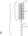
图1按照瓶刷形式构成的按照本发明装置的放大图; Fig. 1 is formed according to the magnified view of device of the present invention according to bottle brush form;
图2按照本发明的装置与一个带有捕获笼的装置的组合的放大图; Fig. 2 is according to the enlarged view of the combination of device of the present invention and a device that has capture cage;
图3按照本发明的装置与附加的捕获笼的放大图; Fig. 3 is according to the enlarged view of device of the present invention and additional capture cage;
图4导引丝与设置在其上的捕获笼的放大图; Figure 4 is an enlarged view of the guide wire and the capture cage arranged thereon;
图5按照本发明的装置的另一实施形式在折叠的形式下的侧视图、正视图; Fig. 5 is according to the side view of another embodiment form of device of the present invention under the folded form, front view;
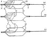
图6按照图5的笼结构的支撑的走向变化; Fig. 6 changes according to the trend of the support of the cage structure of Fig. 5;
图7正交的结构与图5中的支撑的连接变化; The connection change between the orthogonal structure in Fig. 7 and the support in Fig. 5;
图8按照本发明的装置的捕获笼的结构的另一变化; Fig. 8 is according to another variation of the structure of the capture cage of device of the present invention;
图9按照本发明的以尼龙纤维张紧的捕获笼; Fig. 9 is according to the capture cage of nylon fiber tension according to the present invention;
图10按照本发明的具有捕获笼与间隔部件的装置的另一变化; Fig. 10 has another variation of the device with capture cage and spacer according to the present invention;
图11按照本发明的具有绷上的聚合物皮的装置的另一实施形式; Fig. 11 according to another embodiment of the device of the polymer skin that stretches on according to the present invention;
图12按照本发明的装置具有交叉延伸的捕获笼支撑的另一实施形式。 FIG. 12 shows another embodiment of the device according to the invention with cross-extending cage supports. the
具体实施方式Detailed ways
在图1中示出的按照本发明的装置1在直径为0.254mm的由尼龙制成的导引丝2的远端部上具有一个用于取出血栓的瓶刷式功能单元3。该功能单元3具有长度为2mm的聚酰胺刷毛4,它们径向安置在导引丝2上。因此该功能单元3的直径为4mm并且适用于从约4.5至5mm内径的血管中取出血栓。所述导引丝2在带有刷毛的区域由铂微螺旋5构成;这种实施形式特别柔韧并且同时用作X射线技术监控抓取的不透辐射的标记。微螺旋的远端尖端终结在一个特别防止损伤而倒圆角的头部中。 所述刷毛4机械地夹紧在螺旋上,其中分别使一根构成两个刷毛4的纤维以略大于两倍刷毛长度横向于螺旋夹紧并由此构成两根对置的刷毛,它们从螺旋中伸出来。这些刷毛以纤维蛋白覆层,用于保证使血栓良好地粘附在装置1上。 The device 1 according to the invention shown in FIG. 1 has, at the distal end of a
从前面借助一个例如0.67mm内径的微导管6使该装置1以远端部分穿过血管系统移动到被血栓阻塞的血管中。在那里在X射线监控正确定位的条件下,通过现有技术的常见的方法使装置从导管中出来,在血栓旁边或者穿过血栓导引。在此刷毛4由于机械阻力指向近端。接着将装置向着近端拉回,其中刷毛竖立,钩在血栓内并且使血栓与其一起在微导管6中导引,接着从血管系统中取出血栓。 The device 1 is moved from the front with the aid of a microcatheter 6 with an internal diameter of eg 0.67 mm through the vascular system at the distal end into the blood vessel blocked by the thrombus. There, with X-ray monitoring of the correct positioning, the device is brought out of the catheter by conventional methods of the prior art and guided next to or through the thrombus. The
图2示出按照本发明的装置1与瓶刷式构成的功能单元3的组合,该功能单元具有一个带有一个由支撑12构成的血栓捕获笼7的装置。两个装置具有独立的导引丝2/2',但是在附图中没有单独示出它们。所述捕获笼7由镍钛诺制成并且可以具有一些(在附图中未示出的)网孔,它们分布在其基体上。在捕获笼的近端和远端上,不透辐射的铂制标记9位于带有捕获笼7的装置的导引丝2'上,用于X射线检测。该捕获笼7通过由微导管6施加的机械约束在其通过微导管期间保持在压缩状态。在从微导管6移出来以后,捕获笼由于失去约束执行应力感应的马氏体转变并且占据其在图2中示出的膨胀形态。在该形态下,捕获笼具有一个以适宜的方式基本等于或略大于该装置1的功能单元3的外径但小于待治疗的血管内径的外径。在笼7从微导管6中移出来以后,将在同一微导管6中导引的装置1的远端区域同样由微导管6穿过笼7导引到血栓内。接着使装置1与位于功能单元3中的血栓一起拉到笼7中。一旦功能单元3与血栓位于笼7中,使两个装置在避免两个装置相互间相对运动的条件下共同拉回到微导管6中。在此该笼作为防止血栓或者其碎块脱离装置1的保险装置。 FIG. 2 shows the combination of the device 1 according to the invention with a bottlebrush-like functional unit 3 having a device with a
图3示出按照本发明的具有附加捕获笼7'的装置1'的另一实施形式,该捕获笼安置在同一导引丝上,瓶刷式构成的具有径向安置的刷毛4的功能单元3也位于导引丝上。该导引丝2在这里完全由镍钛诺制成。刷 毛4在功能单元3的区域内通过永久粘合剂粘接地固定在该区域。该装置1'具有两个铂制不透辐射的标记9/9',它们位于捕获笼7'的近端和远端。该捕获笼具有一种网孔结构,它从近端朝远端那边压缩,因此在装置1'从血管中回拉时保证更好地防止血栓碎块从笼中滑出。在笼的近端区域内较宽的网孔宽度易于使笼在结构折叠并包围血栓的条件下拉回到导管内,血栓附加地通过刷毛固定在捕获笼中。 FIG. 3 shows another embodiment of the device 1' according to the invention with an additional capture cage 7' mounted on the same guide wire, a bottle brush-like functional unit with radially arranged
要指出,按照本发明的装置也适用于取出异物,例如栓化螺旋(Embolisierungsspiralen)或支架(Stents)。 It should be pointed out that the device according to the invention is also suitable for removing foreign bodies, such as embolization spirals or stents. the
图4示出捕获笼的一种简单的实施形式,如同上面结合图3已经描述的那样。该捕获笼在这种情况下由一个外部的丝结构和一些由一种形状记忆材料如镍钛诺制成的加强支撑以及一个设置在其中的由一种凝血酶原材料如聚氨酯、聚酰胺或类似原料制成的网组成。这些材料也可以覆层。该笼结构在从微导管中释放出来以后展开,并且能够有利地通过近端收缩的夹持形状在捕获血栓以后在拉回到微导管内时重新折叠。 FIG. 4 shows a simple embodiment of a capture cage, as already described above in conjunction with FIG. 3 . The capture cage consists in this case of an outer wire structure and some reinforcing supports made of a shape-memory material such as nitinol and a thrombin raw material such as polyurethane, polyamide or the like disposed therein. Mesh composition made from raw materials. These materials can also be clad. The cage structure unfolds after being released from the microcatheter and can advantageously be refolded when pulled back into the microcatheter after capturing the thrombus by the clamping shape of the proximal constriction. the
在附图中以12表示丝夹持,以11表示网结构。以10表示加强支撑。 In the drawings, 12 indicates the wire clamping, and 11 indicates the mesh structure. A score of 10 indicates strengthening support. the
图5示出按照本发明装置的另一种变化,用于借助导引丝或推进丝(Puscherdraht)2提取血栓,导引丝过渡到笼结构7,它具有总共四个均匀分布在圆周上的支撑12。支撑12由镍钛诺制成,也具有形状记忆特性。它们从一个近端的标记9延伸到一个同时构成套的标记9',该套使支撑12相对于笼结构成束。在所示情况下,该笼结构具有四个支撑,它们分别相对错置90°;也可以轻而易举地实现具有或多或少的支撑和在圆上均匀或不均匀分布的其它结构。所述导引丝2向着远端标记9过渡到近端的丝21,它伸进螺旋形缠绕的导引部件22中。该导引部件22由一根具有标记特性的铂/铱丝制成。一个第二丝段23位于这个导引部件22的远端部上,该丝段终结在远端的标记9'中。远端的丝段23可以与铂导引部件22固定连接或者在其中导引。一个防止损伤的尖端14以铂或塑料半球的形状位于远端标记9'的远端部上。 5 shows another variation of the device according to the invention for extracting a thrombus by means of a guide wire or pusher wire (Puscherdraht) 2, the guide wire transitioning to a
在该装置中,远端部件由近端的丝部件21、导向体22、远端的丝部件23以及粘附在导向体22上的纤维束或刷毛束4组成。所述纤维束可 以植入到丝圈22中或者粘接在其上,必要时也可以熔接在其上。图5b示出从远端标记9’看去的配置5a,具有在中心的防止损伤的尖端14、以900间隔设置的支撑12以及围绕支撑设置的纤维束4。这些纤维束在所示情况下设置在四个阶段上并且相互对准。 In this device, the distal part consists of a
图5c示出从图5a引入一个微导管6中的装置,具有伸直的支撑12和扎起的纤维4。可以看出,与图5a相比在标记9与9’之间的距离由于支撑12的伸展已经变大。 FIG. 5c shows the device introduced from FIG. 5a into a microcatheter 6 with straightened
图6示出与按照图5的装置不同的支撑导向的两个变化。相对于导引丝2或其在远端部件3中的远端延长部,对于一个支撑12在相互错置900情况下,得到所示丝走向的起点和终点,其中支撑12向着观察者延伸。沿导引丝2方向观察时,得到基本四分之三圆的支撑12走向,其中要考虑到,起点和终点通过笼结构的长度7相互分开。 FIG. 6 shows two variants of the support guidance that differ from the arrangement according to FIG. 5 . With respect to the
所述支撑12的这种走向使治疗医生通过小心地推进捕获装置能够刮去粘附在血管壁上的血栓。 This orientation of the
图6b示出另一变化,其中支撑12首先以900旋转延伸到观察者,在那里其导引丝最远的点基本达到以M表示的中心并且接着再返回,由此使起点与终点没有相互错位。在此这种变化有助于避免在推拉时的旋转运动和血栓加载并且同时提供了一种纵向缓冲 
图7示意示出用于使纤维4与笼结构的支撑12连接的变化。纤维4从导向体22的缠圈引出,围绕支撑12缠绕并再返回到导向体22。由此在笼结构从导管中拉出展开以后实现纤维4正交于导向体22走向的约束取向。 Figure 7 schematically shows a variant for connecting the
图8示出一个实施形式的三个不同变化,在其中笼7在其远端部上具有一些附加的支撑或回环8,它们更密地形成笼的远端部。为了清晰起见,在各笼中只分别示出至少四个支撑12中的两个支撑,用于表示原理。此外完全或部分地省去了“瓶刷”的中心部件。 FIG. 8 shows three different variants of an embodiment in which the
图8a示出具有支撑12和其标记9’(远端)和9(近端)的笼。该导引丝2穿过近端标记9延伸并过渡到导向体22。在支撑12上固定一个椭圆环15,一些回环形构成的支撑8围绕该椭圆环导引。这些回环形的支 撑8开始和终结在标记螺旋9'之内,它们同时作为用于支撑12和8的轴环并且松散地围绕环15导引。环15的椭圆结构能够使支撑或回环8在导管之内和之外方便地适配于捕获笼的伸展状态,在环中在支撑12上的固定点不位于相同的高度上。 Figure 8a shows a cage with a
不言而喻,在这种和其他的实施形式中,标记螺旋9和9'分别具有双重功能。一方面它们作为标记,另一方面作为连接支撑8和12的轴环,它们在内部并且必要时也与这个轴环形锁合或材料锁合地连接。 It goes without saying that, in this and other embodiments, the marking
图8b示出另一实施形式,在其中椭圆环15穿过眼圈14引到支撑12上。其它方面这种实施形式对应于图8a的实施形式。 FIG. 8 b shows another embodiment in which the
图8c省去环15并且使回环10直接与支撑12的眼圈14连接。不言而喻,回环或支撑10在其走向上适配于笼结构,即,具有对应于支撑12的走向。 FIG. 8 c omits the
在图9中示出其它实施形式,它们为了简化起见同样只示出支撑的一部分。在图9a和9b中未示出正交的结构。 Other embodiments are shown in FIG. 9 , which likewise only show a part of the support for the sake of simplicity. Orthogonal structures are not shown in Figures 9a and 9b. the
图9a示出按照本发明的笼结构,其中导引丝2穿过近端标记9过渡到导向体22并且终结在远端标记9'。所述支撑12在其长度的一部分上尤其在远端区域内具有一个由铂铱合金制成的标记螺旋组成的缠圈或环绕圈以及一个具有纤维材料16的缠绕圈,它从远端部开始包围支撑12的长度的一部分。这个缠绕圈例如可以由尼龙纤维制成,它们压入到标记螺旋的圈缝隙中并且优选以拉力实现,即整个缠绕圈由一根单丝制成。压进或粘接在支撑12的标记螺旋18上同时起到使支撑固定在其位置和使其相互相对间隔的作用。 FIG. 9 a shows a cage structure according to the invention, in which the
图9b示出另一变化,其中一个具有总共七根支撑12的笼由一根尼龙长丝缠绕。与图9a一样,只包括笼的一部分即远端区域的缠绕在这里可选择地在内部和外部围绕支撑12敷设并且还起到很大程度的固定作用。标记符号22表示中心导向体,它包围导引丝2的各个部件。在此支撑12具有标记螺旋18。 Figure 9b shows another variation in which a cage with a total of seven
在图10a中示出支撑12在其位置上相互尽可能的固定,其中示出两个支撑12,它们通过一个柔韧的夹钳19相互连接。或者可以形锁合或者 可以材料锁合(焊接、粘接)地实现具有“V形体”的连接。在这里支撑12通过由铂铱合金制成的标记螺旋包壳,它可以用于固定夹钳19。 In FIG. 10 a , the
在图10b中以完整的笼的横截面图示出图10a的实施形式。各个支撑12,在这种情况下是6根支撑,通过各夹钳19相互连接。在本身由一个螺旋组成的中心导向体22与支撑12之间导引正交结构的单丝4,它们以回环围绕相应的纵向部件12和22敷设。 The embodiment of FIG. 10 a is shown in FIG. 10 b in a cross-sectional view of the complete cage. The individual supports 12 , in this case 6 supports, are connected to each other by
图11示出另一变化,它与图3和4的具有网结构的变化相关。在这种情况下,笼在其远端区域内用一个例如由膨胀的PTFE制成的聚合物皮17绷上,它使笼的远端部变成一个袋。聚合物皮从笼的远端尖端沿着支撑一直延伸到一个所期望的位置,例如基本在笼的中心。 FIG. 11 shows another variant, which is related to the variant of FIGS. 3 and 4 with a mesh structure. In this case, the cage is covered in its distal region with a
在此聚合物皮的近端棱边优选波形地延伸,由此使在两个支撑之间的棱边区域(a)比支撑本身的区域(b)更靠近远端。所述支撑可以嵌入到聚合物皮中或者粘接在聚合物皮上。 In this case, the proximal edge of the polymer skin preferably runs in a wave-like fashion, so that the edge region (a) between two supports is located farther distally than the region (b) of the supports themselves. The support can be embedded in the polymer skin or glued to the polymer skin. the
图11b示出另一变化,具有与图11a相比不同的聚合物皮棱边走向,它在支撑12上更向着远端牵引。由此保持支撑相互间的尽可能固定。在支撑之间聚合物皮向着近端沉入。这种棱边结构的稳定性可以通过连接支撑和夹钳17实现,如同在图10a中所描述的那样。 FIG. 11 b shows a further variant with a different course of the edge of the polymer skin compared to FIG. 11 a , which is drawn more distally on the
图12仅示出支撑12走向的特殊形状,它们从远端向近端以180°相互错开地延伸,即从笼结构的顶面延伸到底面。在图12b中示出支撑对相对于导向体22的布置,具有一个支撑对12和12'。不言而喻,笼结构在这里本质上是双笼结构,由至少两个优选至少三个支撑对组成,它们均匀地分布在圆周上。 FIG. 12 only shows the special shape of the course of the
所述结构能够这样利用径向力在支撑中通过在对置的侧面上导引,使得笼在各种情况下都得到其张紧的形状,即使当在狭窄的血管中不能实现额定直径的时候。这一点尤其适用于与导向体22和由此实现的纵向适配性相结合。 The structure can be guided with radial forces in the support by being guided on opposite sides in such a way that the cage assumes its tensioned shape in each case, even when the nominal diameter cannot be achieved in narrow vessels . This applies in particular in combination with the
不言而喻,在本发明的实施例中,“远端”和“近端’’的概念是相对于治疗医生而言。因此例如捕获笼或导管的远离治疗医生的端部称为“远端”。 It goes without saying that in the embodiments of the present invention, the concepts of "distal end" and "proximal end" are relative to the treating doctor. Therefore, for example, the end of a capture cage or catheter that is far away from the treating doctor is called "distal end". end".
Claims (17)
Applications Claiming Priority (3)
| Application Number | Priority Date | Filing Date | Title |
|---|---|---|---|
| DE102004040868ADE102004040868A1 (en) | 2004-08-23 | 2004-08-23 | Device for removing thrombi |
| DE102004040868.8 | 2004-08-23 | ||
| PCT/EP2005/009057WO2006021407A2 (en) | 2004-08-23 | 2005-08-22 | Device for the removal of thromboses |
Publications (2)
| Publication Number | Publication Date |
|---|---|
| CN101035474A CN101035474A (en) | 2007-09-12 |
| CN101035474Btrue CN101035474B (en) | 2013-02-27 |
Family
ID=35500794
Family Applications (1)
| Application Number | Title | Priority Date | Filing Date |
|---|---|---|---|
| CN2005800335786AExpired - Fee RelatedCN101035474B (en) | 2004-08-23 | 2005-08-22 | Devices used to remove blood clots |
Country Status (7)
| Country | Link |
|---|---|
| US (3) | US20090306702A1 (en) |
| EP (3) | EP1885257A2 (en) |
| JP (1) | JP2008510541A (en) |
| CN (1) | CN101035474B (en) |
| DE (1) | DE102004040868A1 (en) |
| ES (2) | ES2541219T3 (en) |
| WO (1) | WO2006021407A2 (en) |
Families Citing this family (184)
| Publication number | Priority date | Publication date | Assignee | Title |
|---|---|---|---|---|
| US8425549B2 (en) | 2002-07-23 | 2013-04-23 | Reverse Medical Corporation | Systems and methods for removing obstructive matter from body lumens and treating vascular defects |
| US7686825B2 (en) | 2004-03-25 | 2010-03-30 | Hauser David L | Vascular filter device |
| DE102004040868A1 (en)* | 2004-08-23 | 2006-03-09 | Miloslavski, Elina | Device for removing thrombi |
| US7931659B2 (en)* | 2004-09-10 | 2011-04-26 | Penumbra, Inc. | System and method for treating ischemic stroke |
| US9655633B2 (en)* | 2004-09-10 | 2017-05-23 | Penumbra, Inc. | System and method for treating ischemic stroke |
| US20080172066A9 (en)* | 2005-07-29 | 2008-07-17 | Galdonik Jason A | Embolectomy procedures with a device comprising a polymer and devices with polymer matrices and supports |
| DE102005059670A1 (en)* | 2005-12-12 | 2007-06-14 | Phenox Gmbh | Device for removing thrombi from blood vessels |
| BRPI0707681A2 (en) | 2006-02-01 | 2011-05-10 | Cleveland Clinic Foudation | Method and apparatus for increasing blood flow through a blocked artery |
| EP1986568B1 (en) | 2006-02-03 | 2017-04-05 | Covidien LP | Methods and devices for restoring blood flow within blocked vasculature |
| DE102006044831A1 (en)* | 2006-09-20 | 2008-04-03 | Phenox Gmbh | Device for removing thrombi from blood vessels |
| US8795197B2 (en)* | 2007-07-17 | 2014-08-05 | Histologics, LLC | Frictional trans-epithelial tissue disruption collection apparatus and method of inducing an immune response |
| US9034007B2 (en) | 2007-09-21 | 2015-05-19 | Insera Therapeutics, Inc. | Distal embolic protection devices with a variable thickness microguidewire and methods for their use |
| US8926680B2 (en) | 2007-11-12 | 2015-01-06 | Covidien Lp | Aneurysm neck bridging processes with revascularization systems methods and products thereby |
| US8088140B2 (en) | 2008-05-19 | 2012-01-03 | Mindframe, Inc. | Blood flow restorative and embolus removal methods |
| US8585713B2 (en) | 2007-10-17 | 2013-11-19 | Covidien Lp | Expandable tip assembly for thrombus management |
| US9220522B2 (en) | 2007-10-17 | 2015-12-29 | Covidien Lp | Embolus removal systems with baskets |
| US10123803B2 (en) | 2007-10-17 | 2018-11-13 | Covidien Lp | Methods of managing neurovascular obstructions |
| US11337714B2 (en) | 2007-10-17 | 2022-05-24 | Covidien Lp | Restoring blood flow and clot removal during acute ischemic stroke |
| US8066757B2 (en) | 2007-10-17 | 2011-11-29 | Mindframe, Inc. | Blood flow restoration and thrombus management methods |
| US20100022951A1 (en)* | 2008-05-19 | 2010-01-28 | Luce, Forward, Hamilton 7 Scripps, Llp | Detachable hub/luer device and processes |
| US9198687B2 (en) | 2007-10-17 | 2015-12-01 | Covidien Lp | Acute stroke revascularization/recanalization systems processes and products thereby |
| US11589880B2 (en) | 2007-12-20 | 2023-02-28 | Angiodynamics, Inc. | System and methods for removing undesirable material within a circulatory system utilizing during a surgical procedure |
| US10517617B2 (en) | 2007-12-20 | 2019-12-31 | Angiodynamics, Inc. | Systems and methods for removing undesirable material within a circulatory system utilizing a balloon catheter |
| US20170136158A1 (en) | 2015-10-16 | 2017-05-18 | Angiodynamics, Inc. | Systems and Methods for Removing Undesirable Material Within a Circulatory System |
| US8858609B2 (en)* | 2008-02-07 | 2014-10-14 | Intuitive Surgical Operations, Inc. | Stent delivery under direct visualization |
| JP5457373B2 (en) | 2008-02-22 | 2014-04-02 | コヴィディエン リミテッド パートナーシップ | Device for blood flow recovery |
| ES2848392T3 (en) | 2008-03-02 | 2021-08-09 | V V T Medical Ltd | Vein ablation device |
| CN101977650A (en) | 2008-04-11 | 2011-02-16 | 曼德弗雷姆公司 | Monorail neural microcatheter for delivery of medical device for treatment of stroke, methods and products thereof |
| EP2633823B1 (en) | 2008-04-21 | 2016-06-01 | Covidien LP | Braid-ball embolic devices and delivery systems |
| WO2009140437A1 (en) | 2008-05-13 | 2009-11-19 | Nfocus Neuromedical, Inc. | Braid implant delivery systems |
| EP2341845B1 (en) | 2008-07-22 | 2016-01-06 | Neuravi Limited | Clot capture systems |
| US9402707B2 (en) | 2008-07-22 | 2016-08-02 | Neuravi Limited | Clot capture systems and associated methods |
| DE102008038195A1 (en) | 2008-08-19 | 2010-02-25 | Phenox Gmbh | Device for opening occluded blood vessels |
| WO2010075445A1 (en) | 2008-12-23 | 2010-07-01 | Silk Road Medical, Inc. | Methods and systems for treatment of acute ischemic stroke |
| US20100204672A1 (en)* | 2009-02-12 | 2010-08-12 | Penumra, Inc. | System and method for treating ischemic stroke |
| US8361095B2 (en)* | 2009-02-17 | 2013-01-29 | Cook Medical Technologies Llc | Loop thrombectomy device |
| EP2403583B1 (en) | 2009-03-06 | 2016-10-19 | Lazarus Effect, Inc. | Retrieval systems |
| DE102009011931A1 (en) | 2009-03-10 | 2010-09-16 | Innora Gmbh | Device for applying active substances to the wall of a body vessel |
| KR101135154B1 (en)* | 2010-02-19 | 2012-04-16 | 주식회사 라파스 | Stent delivery devices using micro cadeter |
| CA2804254C (en) | 2010-02-23 | 2016-11-01 | Medina Medical, Inc. | Devices and methods for vascular recanalization |
| EP2558005B1 (en) | 2010-04-13 | 2022-03-30 | MIVI Neuroscience, Inc | Embolectomy devices for treatment of acute ischemic stroke condition |
| US20120059247A1 (en)* | 2010-09-03 | 2012-03-08 | Speeg Trevor W V | Echogenic needle for biopsy device |
| US10039900B2 (en)* | 2010-09-07 | 2018-08-07 | Angiodynamics, Inc. | Fluid delivery and treatment device and method of use |
| EP2629676B1 (en)* | 2010-10-19 | 2016-07-13 | United States Endoscopy Group, Inc. | Cytology brush apparatus with improvements |
| ES2683943T3 (en) | 2010-10-22 | 2018-09-28 | Neuravi Limited | Clot capture and removal system |
| DE102010051740A1 (en) | 2010-11-19 | 2012-05-24 | Phenox Gmbh | thrombectomy |
| EP3156004B1 (en)* | 2011-02-04 | 2018-04-11 | Concentric Medical, Inc. | Vascular and bodily duct treatment devices |
| DE102011012501A1 (en) | 2011-02-25 | 2012-08-30 | Phenox Gmbh | Implant with fiber fleece |
| US12076037B2 (en) | 2011-03-09 | 2024-09-03 | Neuravi Limited | Systems and methods to restore perfusion to a vessel |
| US11259824B2 (en) | 2011-03-09 | 2022-03-01 | Neuravi Limited | Clot retrieval device for removing occlusive clot from a blood vessel |
| EP4566553A3 (en) | 2011-03-09 | 2025-08-06 | Neuravi Limited | A clot retrieval device for removing occlusive clot from a blood vessel |
| US9055964B2 (en) | 2011-03-15 | 2015-06-16 | Angio Dynamics, Inc. | Device and method for removing material from a hollow anatomical structure |
| US12245788B2 (en) | 2011-03-15 | 2025-03-11 | Angiodynamics, Inc. | Device and method for removing material from a hollow anatomical structure |
| DE102011101522A1 (en) | 2011-05-13 | 2012-11-15 | Phenox Gmbh | thrombectomy |
| US20120330350A1 (en)* | 2011-06-27 | 2012-12-27 | Jones Donald K | Methods and systems for performing thrombectomy procedures |
| EP4101399B1 (en) | 2011-08-05 | 2025-04-09 | Route 92 Medical, Inc. | System for treatment of acute ischemic stroke |
| US10779855B2 (en) | 2011-08-05 | 2020-09-22 | Route 92 Medical, Inc. | Methods and systems for treatment of acute ischemic stroke |
| CN103732181B (en) | 2011-08-12 | 2016-05-04 | W.L.戈尔及同仁股份有限公司 | Be used for the device of the cross-sectional profiles of the approximate vascular system with branch |
| US20130204234A1 (en)* | 2011-08-12 | 2013-08-08 | Edward H. Cully | Systems for the reduction of leakage around medical devices at a treatment site |
| US12096951B2 (en) | 2011-10-05 | 2024-09-24 | Penumbra, Inc. | System and method for treating ischemic stroke |
| ES2671045T3 (en) | 2012-01-15 | 2018-06-04 | Triticum Ltd. | Device to remove occlusions of a biological vessel |
| CN103417261B (en)* | 2012-05-14 | 2016-03-30 | 微创神通医疗科技(上海)有限公司 | Intracranial vessel gets pin device |
| CN103417258B (en)* | 2012-05-14 | 2015-11-25 | 上海微创医疗器械(集团)有限公司 | Intracranial vessel gets pin device |
| US9211132B2 (en)* | 2012-06-27 | 2015-12-15 | MicoVention, Inc. | Obstruction removal system |
| WO2014047650A1 (en) | 2012-09-24 | 2014-03-27 | Inceptus Medical LLC | Device and method for treating vascular occlusion |
| US10327781B2 (en) | 2012-11-13 | 2019-06-25 | Covidien Lp | Occlusive devices |
| US8784434B2 (en) | 2012-11-20 | 2014-07-22 | Inceptus Medical, Inc. | Methods and apparatus for treating embolism |
| US20150289892A1 (en)* | 2012-11-21 | 2015-10-15 | The Hong Kong University Of Science And Technology | Low Force Thrombectomy Device |
| US9271818B2 (en)* | 2013-02-25 | 2016-03-01 | Cook Medical Technologies Llc | Conical vena cava filter with jugular or femoral retrieval |
| EP2967472A4 (en)* | 2013-03-13 | 2016-10-05 | Angiosafe Inc | Device and method for treating a chronic total occlusion |
| US9642635B2 (en) | 2013-03-13 | 2017-05-09 | Neuravi Limited | Clot removal device |
| US9433429B2 (en) | 2013-03-14 | 2016-09-06 | Neuravi Limited | Clot retrieval devices |
| WO2014140092A2 (en) | 2013-03-14 | 2014-09-18 | Neuravi Limited | Devices and methods for removal of acute blockages from blood vessels |
| ES2708786T3 (en) | 2013-03-14 | 2019-04-11 | Neuravi Ltd | Clot recovery device to remove occlusive clots from a blood vessel |
| US8679150B1 (en) | 2013-03-15 | 2014-03-25 | Insera Therapeutics, Inc. | Shape-set textile structure based mechanical thrombectomy methods |
| KR102445703B1 (en)* | 2013-03-15 | 2022-09-20 | 엠보 메디칼 리미티드 | Embolisation systems |
| US8715314B1 (en) | 2013-03-15 | 2014-05-06 | Insera Therapeutics, Inc. | Vascular treatment measurement methods |
| CN105228688B (en) | 2013-03-15 | 2019-02-19 | 伊瑟拉医疗公司 | Vascular treatment devices and methods |
| US10675039B2 (en) | 2013-03-15 | 2020-06-09 | Embo Medical Limited | Embolisation systems |
| US8690907B1 (en) | 2013-03-15 | 2014-04-08 | Insera Therapeutics, Inc. | Vascular treatment methods |
| US10660645B2 (en) | 2013-03-15 | 2020-05-26 | Embo Medical Limited | Embolization systems |
| WO2014204860A1 (en) | 2013-06-18 | 2014-12-24 | Slik Road Medical, Inc. | Methods and systems for tretment of acute ischemic stroke |
| US9259237B2 (en) | 2013-07-12 | 2016-02-16 | Inceptus Medical, Llc | Methods and apparatus for treating pulmonary embolism |
| US10238406B2 (en) | 2013-10-21 | 2019-03-26 | Inari Medical, Inc. | Methods and apparatus for treating embolism |
| US9265512B2 (en) | 2013-12-23 | 2016-02-23 | Silk Road Medical, Inc. | Transcarotid neurovascular catheter |
| US10285720B2 (en) | 2014-03-11 | 2019-05-14 | Neuravi Limited | Clot retrieval system for removing occlusive clot from a blood vessel |
| US9241699B1 (en) | 2014-09-04 | 2016-01-26 | Silk Road Medical, Inc. | Methods and devices for transcarotid access |
| EP3136944B1 (en) | 2014-05-02 | 2020-03-25 | United States Endoscopy Group, Inc. | Cleaning device for an endoscopic device |
| CN106470728A (en) | 2014-06-09 | 2017-03-01 | 因赛普特斯医学有限责任公司 | Retraction and suction device and related systems and methods for treating embolism |
| JP6595513B2 (en) | 2014-06-13 | 2019-10-23 | ニューラヴィ・リミテッド | Device for removal of acute occlusions from blood vessels |
| US10792056B2 (en) | 2014-06-13 | 2020-10-06 | Neuravi Limited | Devices and methods for removal of acute blockages from blood vessels |
| WO2015195774A1 (en)* | 2014-06-18 | 2015-12-23 | Cook Medical Technologies Llc | Brush system for a cell collecting device |
| US10265086B2 (en) | 2014-06-30 | 2019-04-23 | Neuravi Limited | System for removing a clot from a blood vessel |
| US11027104B2 (en) | 2014-09-04 | 2021-06-08 | Silk Road Medical, Inc. | Methods and devices for transcarotid access |
| EP3682821B1 (en) | 2014-11-26 | 2022-05-11 | Neuravi Limited | A clot retrieval device for removing an occlusive clot from a blood vessel |
| US10617435B2 (en) | 2014-11-26 | 2020-04-14 | Neuravi Limited | Clot retrieval device for removing clot from a blood vessel |
| US11253278B2 (en) | 2014-11-26 | 2022-02-22 | Neuravi Limited | Clot retrieval system for removing occlusive clot from a blood vessel |
| US11771446B2 (en) | 2020-10-19 | 2023-10-03 | Anaconda Biomed, S.L. | Thrombectomy system and method of use |
| ES2577288B8 (en) | 2015-01-13 | 2019-01-10 | Anaconda Biomed S L | Device for thrombectomy |
| WO2016120864A2 (en) | 2015-01-28 | 2016-08-04 | Triticum Ltd. | Device and method for removing occlusions in a biological vessel |
| US10426497B2 (en) | 2015-07-24 | 2019-10-01 | Route 92 Medical, Inc. | Anchoring delivery system and methods |
| US11065019B1 (en) | 2015-02-04 | 2021-07-20 | Route 92 Medical, Inc. | Aspiration catheter systems and methods of use |
| CN119949953A (en) | 2015-02-04 | 2025-05-09 | 92号医疗公司 | Intravascular access system, dilator and system including dilator |
| EP3256200A1 (en) | 2015-02-11 | 2017-12-20 | Covidien LP | Expandable tip medical devices and methods |
| US11779435B2 (en)* | 2015-08-26 | 2023-10-10 | Flexscrewdriver I.K.E. | Dental screwdriver |
| WO2017040681A1 (en) | 2015-09-01 | 2017-03-09 | Mivi Neuroscience, Inc. | Thrombectomy devices and treatment of acute ischemic stroke with thrombus engagement |
| US12082845B2 (en) | 2015-09-04 | 2024-09-10 | The Trustees Of The University Of Pennsylvania | Systems and methods for percutaneous removal of objects from an internal body space |
| EP3344167B1 (en) | 2015-09-04 | 2021-12-01 | The Trustees of The University of Pennsylvania | Systems for percutaneous removal of objects from an internal body space |
| JP6591664B2 (en)* | 2015-09-21 | 2019-10-16 | ストライカー コーポレイションStryker Corporation | Embolization removal device |
| US10342571B2 (en) | 2015-10-23 | 2019-07-09 | Inari Medical, Inc. | Intravascular treatment of vascular occlusion and associated devices, systems, and methods |
| CN113796927B (en) | 2015-10-23 | 2025-03-04 | 伊纳里医疗公司 | Intravascular treatment of vascular occlusion and related devices, systems and methods |
| US9700332B2 (en) | 2015-10-23 | 2017-07-11 | Inari Medical, Inc. | Intravascular treatment of vascular occlusion and associated devices, systems, and methods |
| CN115300748A (en) | 2015-12-18 | 2022-11-08 | 伊纳里医疗有限公司 | Catheter shaft and related devices, systems and methods |
| CN108697423A (en) | 2016-02-16 | 2018-10-23 | 伊瑟拉医疗公司 | The part flow arrangement of suction unit and anchoring |
| EP3500191B1 (en) | 2016-08-17 | 2020-09-23 | Neuravi Limited | A clot retrieval system for removing occlusive clot from a blood vessel |
| EP3509509B1 (en) | 2016-09-06 | 2021-03-31 | Neuravi Limited | A clot retrieval device for removing occlusive clot from a blood vessel |
| US12369932B2 (en) | 2016-09-07 | 2025-07-29 | Daniel Ezra Walzman | Methods and devices to ameliorate vascular obstruction |
| US11877752B2 (en) | 2016-09-07 | 2024-01-23 | Daniel Ezra Walzman | Filterless aspiration, irrigating, macerating, rotating microcatheter and method of use |
| US10314684B2 (en)* | 2016-09-07 | 2019-06-11 | Daniel Ezra Walzman | Simultaneous rotating separator, irrigator microcatheter for thrombectomy |
| US12138149B2 (en) | 2016-09-07 | 2024-11-12 | Daniel Ezra Walzman | Endovascular devices and methods with filtering elements |
| US11259820B2 (en)* | 2016-09-07 | 2022-03-01 | Daniel Ezra Walzman | Methods and devices to ameliorate vascular obstruction |
| US10299824B2 (en)* | 2016-09-07 | 2019-05-28 | Daniel Ezra Walzman | Rotating separator, irrigator microcatheter for thrombectomy |
| US11439492B2 (en) | 2016-09-07 | 2022-09-13 | Daniel Ezra Walzman | Lasso filter tipped microcatheter for simultaneous rotating separator, irrigator for thrombectomy and method for use |
| JP2019528824A (en)* | 2016-09-15 | 2019-10-17 | メディノール リミテッドMedinol Ltd. | Blood clot collector |
| AU2017339213A1 (en)* | 2016-10-07 | 2019-05-02 | Body Vision Medical Ltd | Devices for use in interventional and surgical procedures and methods of use thereof |
| US10576099B2 (en) | 2016-10-21 | 2020-03-03 | Covidien Lp | Injectable scaffold for treatment of intracranial aneurysms and related technology |
| FI3528717T3 (en) | 2016-10-24 | 2024-08-09 | Inari Medical Inc | Devices for treating vascular occlusion |
| MX2019006793A (en) | 2016-12-09 | 2019-11-18 | Zanetta Malanowska Stega | Brush biopsy device, kit and method. |
| CN110392591B (en) | 2017-01-10 | 2022-06-03 | 92号医疗公司 | Aspiration catheter system and method of use |
| US10864350B2 (en) | 2017-01-20 | 2020-12-15 | Route 92 Medical, Inc. | Single operator intracranial medical device delivery systems and methods of use |
| WO2019050765A1 (en) | 2017-09-06 | 2019-03-14 | Inari Medical, Inc. | Hemostasis valves and methods of use |
| US11154314B2 (en) | 2018-01-26 | 2021-10-26 | Inari Medical, Inc. | Single insertion delivery system for treating embolism and associated systems and methods |
| DE102018105671A1 (en) | 2018-03-12 | 2019-09-12 | Phenox Gmbh | thrombectomy |
| US20190282247A1 (en)* | 2018-03-15 | 2019-09-19 | Gyrus Acmi, Inc. D/B/A Olympus Surgical Technologies America | Small fragment retrieval device |
| CN108542480A (en)* | 2018-05-16 | 2018-09-18 | 江苏省人民医院(南京医科大学第附属医院) | Bionic sucker foreign matter extractor |
| JP7616642B2 (en) | 2018-05-17 | 2025-01-17 | ルート92メディカル・インコーポレイテッド | Suction catheter system and method of use |
| CA3114285A1 (en) | 2018-08-13 | 2020-02-20 | Inari Medical, Inc. | System for treating embolism and associated devices and methods |
| US10842498B2 (en) | 2018-09-13 | 2020-11-24 | Neuravi Limited | Systems and methods of restoring perfusion to a vessel |
| US11406416B2 (en) | 2018-10-02 | 2022-08-09 | Neuravi Limited | Joint assembly for vasculature obstruction capture device |
| US12285182B2 (en) | 2018-10-10 | 2025-04-29 | Innova Vascular, Inc. | Devices and methods for removing an embolus |
| ES2910600T3 (en) | 2019-03-04 | 2022-05-12 | Neuravi Ltd | Powered Clot Recovery Catheter |
| CN109824264B (en)* | 2019-04-15 | 2023-08-18 | 四川省玻纤集团股份有限公司 | Wire pushing structure of automatic glass fiber cylinder changing wire drawing machine |
| JP2022516573A (en)* | 2019-06-05 | 2022-02-28 | エンドシェープ,アイエヌシー. | Systems, devices, and methods for improving obstruction and delivery |
| JP6970323B2 (en)* | 2019-07-25 | 2021-11-24 | クリアストリーム・テクノロジーズ・リミテッド | Embolic devices for promoting thrombus formation and methods of recovering the embolic devices from body lumens |
| EP3791815B1 (en) | 2019-09-11 | 2024-06-26 | Neuravi Limited | Expandable mouth catheter |
| JP7638273B2 (en) | 2019-10-16 | 2025-03-03 | イナリ メディカル, インコーポレイテッド | Systems, devices and methods for treating vascular obstructions |
| US11712231B2 (en) | 2019-10-29 | 2023-08-01 | Neuravi Limited | Proximal locking assembly design for dual stent mechanical thrombectomy device |
| WO2021092618A1 (en) | 2019-11-04 | 2021-05-14 | Covidien Lp | Devices, systems, and methods for treatment of intracranial aneurysms |
| EP4054481A4 (en)* | 2019-11-07 | 2023-12-13 | Jeko Metodiev Madjarov | Endograft with bristles |
| US11839725B2 (en) | 2019-11-27 | 2023-12-12 | Neuravi Limited | Clot retrieval device with outer sheath and inner catheter |
| US11779364B2 (en) | 2019-11-27 | 2023-10-10 | Neuravi Limited | Actuated expandable mouth thrombectomy catheter |
| US11517340B2 (en) | 2019-12-03 | 2022-12-06 | Neuravi Limited | Stentriever devices for removing an occlusive clot from a vessel and methods thereof |
| WO2021155912A1 (en)* | 2020-02-04 | 2021-08-12 | Clearstream Technologies Limited | Embolisation system for promoting clot formation |
| US11648020B2 (en) | 2020-02-07 | 2023-05-16 | Angiodynamics, Inc. | Device and method for manual aspiration and removal of an undesirable material |
| CN111035432A (en)* | 2020-02-23 | 2020-04-21 | 河南中医药大学 | A thrombus cleaning brush device |
| US11633198B2 (en) | 2020-03-05 | 2023-04-25 | Neuravi Limited | Catheter proximal joint |
| US11944327B2 (en) | 2020-03-05 | 2024-04-02 | Neuravi Limited | Expandable mouth aspirating clot retrieval catheter |
| US11883043B2 (en) | 2020-03-31 | 2024-01-30 | DePuy Synthes Products, Inc. | Catheter funnel extension |
| US11759217B2 (en) | 2020-04-07 | 2023-09-19 | Neuravi Limited | Catheter tubular support |
| US11717308B2 (en) | 2020-04-17 | 2023-08-08 | Neuravi Limited | Clot retrieval device for removing heterogeneous clots from a blood vessel |
| US11730501B2 (en) | 2020-04-17 | 2023-08-22 | Neuravi Limited | Floating clot retrieval device for removing clots from a blood vessel |
| US11871946B2 (en) | 2020-04-17 | 2024-01-16 | Neuravi Limited | Clot retrieval device for removing clot from a blood vessel |
| US11737771B2 (en) | 2020-06-18 | 2023-08-29 | Neuravi Limited | Dual channel thrombectomy device |
| US11937836B2 (en) | 2020-06-22 | 2024-03-26 | Neuravi Limited | Clot retrieval system with expandable clot engaging framework |
| US11439418B2 (en) | 2020-06-23 | 2022-09-13 | Neuravi Limited | Clot retrieval device for removing clot from a blood vessel |
| US11395669B2 (en) | 2020-06-23 | 2022-07-26 | Neuravi Limited | Clot retrieval device with flexible collapsible frame |
| US11864781B2 (en) | 2020-09-23 | 2024-01-09 | Neuravi Limited | Rotating frame thrombectomy device |
| WO2022076893A1 (en) | 2020-10-09 | 2022-04-14 | Route 92 Medical, Inc. | Aspiration catheter systems and methods of use |
| US11937837B2 (en) | 2020-12-29 | 2024-03-26 | Neuravi Limited | Fibrin rich / soft clot mechanical thrombectomy device |
| US12029442B2 (en) | 2021-01-14 | 2024-07-09 | Neuravi Limited | Systems and methods for a dual elongated member clot retrieval apparatus |
| US11872354B2 (en) | 2021-02-24 | 2024-01-16 | Neuravi Limited | Flexible catheter shaft frame with seam |
| US12064130B2 (en) | 2021-03-18 | 2024-08-20 | Neuravi Limited | Vascular obstruction retrieval device having sliding cages pinch mechanism |
| US11679195B2 (en) | 2021-04-27 | 2023-06-20 | Contego Medical, Inc. | Thrombus aspiration system and methods for controlling blood loss |
| US11974764B2 (en) | 2021-06-04 | 2024-05-07 | Neuravi Limited | Self-orienting rotating stentriever pinching cells |
| JP2024524921A (en) | 2021-06-18 | 2024-07-09 | シルク・ロード・メディカル・インコーポレイテッド | Systems and methods for vascular intervention - Patents.com |
| CN113598881B (en)* | 2021-09-07 | 2023-12-29 | 艾柯医疗器械(北京)股份有限公司 | Intravascular foreign body removal device and assembly |
| US20230073028A1 (en)* | 2021-09-08 | 2023-03-09 | Zanetta Malanowska-Stega | Absorptive tip brush biopsy device, kit and method |
| US11937839B2 (en) | 2021-09-28 | 2024-03-26 | Neuravi Limited | Catheter with electrically actuated expandable mouth |
| US12011186B2 (en) | 2021-10-28 | 2024-06-18 | Neuravi Limited | Bevel tip expandable mouth catheter with reinforcing ring |
| EP4463083A1 (en) | 2022-01-11 | 2024-11-20 | Inari Medical, Inc. | Devices for removing clot material from intravascularly implanted devices, and associated systems and methods |
| JP2025506512A (en)* | 2022-02-14 | 2025-03-11 | ボストン サイエンティフィック サイムド,インコーポレイテッド | Tissue sample devices and methods |
| CN120583920A (en)* | 2022-12-21 | 2025-09-02 | 泰尔茂株式会社 | Thrombus taking-out device |
| CN116439783B (en)* | 2023-05-30 | 2024-02-06 | 北京管桥医疗科技有限公司 | Thrombus recovery device |
| WO2025042929A1 (en)* | 2023-08-24 | 2025-02-27 | Boston Scientific Medical Device Limited | Cytology devices |
Citations (3)
| Publication number | Priority date | Publication date | Assignee | Title |
|---|---|---|---|---|
| US5370653A (en)* | 1993-07-22 | 1994-12-06 | Micro Therapeutics, Inc. | Thrombectomy method and apparatus |
| US5902263A (en)* | 1997-02-12 | 1999-05-11 | Prolifix Medical, Inc. | Apparatus and method for removing stenotic material from stents |
| US6620179B2 (en)* | 1999-08-10 | 2003-09-16 | Neurovasx, Inc. | Clot disrupting wire/catheter assembly |
Family Cites Families (36)
| Publication number | Priority date | Publication date | Assignee | Title |
|---|---|---|---|---|
| GB1408140A (en)* | 1971-12-09 | 1975-10-01 | Levene M M | Sampling device |
| JPS5281980A (en)* | 1975-12-28 | 1977-07-08 | Ouchi Teruo | Brush for diagnosing scratched cells |
| US4538612A (en)* | 1983-08-29 | 1985-09-03 | Ndm Corporation | Skin preparation method and product |
| USD317361S (en)* | 1987-06-11 | 1991-06-04 | Medscand Ab | Endometric brush |
| ES2047586T3 (en)* | 1988-03-04 | 1994-03-01 | Angiomed Ag | PROCEDURE AND DEVICE TO REMOVE DEPOSITS OF MATERIAL IN VESSELS AND LIVING BODIES. |
| US4966162A (en)* | 1989-01-25 | 1990-10-30 | Wang Ko P | Flexible encoscope assembly |
| DE3921071A1 (en)* | 1989-06-28 | 1991-02-28 | Rupprecht Hans Juergen | Removing thrombosis from blood vessel - involves semi-rigid rod with attached bristles, given reciprocating and rotating motion |
| US5171233A (en) | 1990-04-25 | 1992-12-15 | Microvena Corporation | Snare-type probe |
| US5100423A (en)* | 1990-08-21 | 1992-03-31 | Medical Engineering & Development Institute, Inc. | Ablation catheter |
| US5176693A (en)* | 1992-05-11 | 1993-01-05 | Interventional Technologies, Inc. | Balloon expandable atherectomy cutter |
| DE9313034U1 (en)* | 1993-08-31 | 1993-10-28 | Georg Karl Geka-Brush Gmbh, 91572 Bechhofen | Cleaning device |
| US5535756A (en)* | 1994-01-06 | 1996-07-16 | Parasher; Vinod K. | Catheter with simultaneous brush cytology and scrape biopsy capability |
| US5496294A (en)* | 1994-07-08 | 1996-03-05 | Target Therapeutics, Inc. | Catheter with kink-resistant distal tip |
| US5713369A (en)* | 1995-09-13 | 1998-02-03 | Vance Products Inc. | Uterine endometrial tissue sample brush |
| US5702413A (en)* | 1996-01-11 | 1997-12-30 | Scimed Life Systems, Inc. | Curved bristle atherectomy device and method |
| US6068623A (en)* | 1997-03-06 | 2000-05-30 | Percusurge, Inc. | Hollow medical wires and methods of constructing same |
| US5730741A (en)* | 1997-02-07 | 1998-03-24 | Eclipse Surgical Technologies, Inc. | Guided spiral catheter |
| US5814064A (en) | 1997-03-06 | 1998-09-29 | Scimed Life Systems, Inc. | Distal protection device |
| US5899850A (en)* | 1997-04-03 | 1999-05-04 | Asahi Kogaku Kogyo Kabushiki Kaisha | Treatment accessories for an endoscope |
| US20040199202A1 (en)* | 1997-11-12 | 2004-10-07 | Genesis Technologies Llc | Biological passageway occlusion removal |
| US6824550B1 (en)* | 2000-04-06 | 2004-11-30 | Norbon Medical, Inc. | Guidewire for crossing occlusions or stenosis |
| US6350271B1 (en) | 1999-05-17 | 2002-02-26 | Micrus Corporation | Clot retrieval device |
| US6458139B1 (en)* | 1999-06-21 | 2002-10-01 | Endovascular Technologies, Inc. | Filter/emboli extractor for use in variable sized blood vessels |
| US6454775B1 (en)* | 1999-12-06 | 2002-09-24 | Bacchus Vascular Inc. | Systems and methods for clot disruption and retrieval |
| US6629953B1 (en)* | 2000-02-18 | 2003-10-07 | Fox Hollow Technologies, Inc. | Methods and devices for removing material from a vascular site |
| US20010031981A1 (en)* | 2000-03-31 | 2001-10-18 | Evans Michael A. | Method and device for locating guidewire and treating chronic total occlusions |
| US6824545B2 (en)* | 2000-06-29 | 2004-11-30 | Concentric Medical, Inc. | Systems, methods and devices for removing obstructions from a blood vessel |
| WO2002055146A1 (en)* | 2001-01-09 | 2002-07-18 | Microvention, Inc. | Embolectomy catheters and method for treatment |
| US20040073252A1 (en)* | 2001-02-20 | 2004-04-15 | Mark Goldberg | Blood clot filtering system |
| US7052500B2 (en)* | 2001-10-19 | 2006-05-30 | Scimed Life Systems, Inc. | Embolus extractor |
| AU2002350164A1 (en)* | 2001-11-08 | 2003-05-19 | William D. Hare | Rapid exchange catheter with stent deployment, therapeutic infusion, and lesion sampling features |
| US6740096B2 (en)* | 2002-01-16 | 2004-05-25 | Scimed Life Systems, Inc. | Treatment and removal of objects in anatomical lumens |
| WO2006007410A2 (en)* | 2004-06-16 | 2006-01-19 | Medtronic, Inc. | Minimally invasive coring vein harvester |
| DE102004040868A1 (en)* | 2004-08-23 | 2006-03-09 | Miloslavski, Elina | Device for removing thrombi |
| US20060184194A1 (en)* | 2005-02-15 | 2006-08-17 | Cook Incorporated | Embolic protection device |
| US20090240164A1 (en)* | 2008-03-18 | 2009-09-24 | Alexandra Jean Gillespie | Device and Method for Collecting Tissue Samples |
- 2004
- 2004-08-23DEDE102004040868Apatent/DE102004040868A1/enactivePending
- 2005
- 2005-08-22WOPCT/EP2005/009057patent/WO2006021407A2/enactiveApplication Filing
- 2005-08-22CNCN2005800335786Apatent/CN101035474B/ennot_activeExpired - Fee Related
- 2005-08-22EPEP05777177Apatent/EP1885257A2/ennot_activeCeased
- 2005-08-22JPJP2007528719Apatent/JP2008510541A/enactivePending
- 2005-08-22ESES11008119.7Tpatent/ES2541219T3/ennot_activeExpired - Lifetime
- 2005-08-22ESES15161473Tpatent/ES2741316T3/ennot_activeExpired - Lifetime
- 2005-08-22EPEP15161473.2Apatent/EP2926747B1/ennot_activeExpired - Lifetime
- 2005-08-22EPEP11008119.7Apatent/EP2404561B1/ennot_activeExpired - Lifetime
- 2006
- 2006-11-09USUS12/084,596patent/US20090306702A1/ennot_activeAbandoned
- 2007
- 2007-02-23USUS11/678,285patent/US9055963B2/enactiveActive
- 2015
- 2015-04-22USUS14/693,493patent/US9707002B2/ennot_activeExpired - Lifetime
Patent Citations (3)
| Publication number | Priority date | Publication date | Assignee | Title |
|---|---|---|---|---|
| US5370653A (en)* | 1993-07-22 | 1994-12-06 | Micro Therapeutics, Inc. | Thrombectomy method and apparatus |
| US5902263A (en)* | 1997-02-12 | 1999-05-11 | Prolifix Medical, Inc. | Apparatus and method for removing stenotic material from stents |
| US6620179B2 (en)* | 1999-08-10 | 2003-09-16 | Neurovasx, Inc. | Clot disrupting wire/catheter assembly |
Also Published As
| Publication number | Publication date |
|---|---|
| EP2404561B1 (en) | 2015-04-01 |
| ES2741316T3 (en) | 2020-02-10 |
| DE102004040868A1 (en) | 2006-03-09 |
| US20090306702A1 (en) | 2009-12-10 |
| US20070198028A1 (en) | 2007-08-23 |
| EP2926747B1 (en) | 2019-05-22 |
| JP2008510541A (en) | 2008-04-10 |
| US20150297252A1 (en) | 2015-10-22 |
| EP2926747A1 (en) | 2015-10-07 |
| EP2404561A2 (en) | 2012-01-11 |
| US9055963B2 (en) | 2015-06-16 |
| US9707002B2 (en) | 2017-07-18 |
| EP1885257A2 (en) | 2008-02-13 |
| ES2541219T3 (en) | 2015-07-16 |
| WO2006021407A2 (en) | 2006-03-02 |
| CN101035474A (en) | 2007-09-12 |
| EP2404561A3 (en) | 2012-03-21 |
| WO2006021407A3 (en) | 2006-06-01 |
Similar Documents
| Publication | Publication Date | Title |
|---|---|---|
| CN101035474B (en) | Devices used to remove blood clots | |
| US12029443B2 (en) | Axial lengthening thrombus capture system | |
| ES2453620T3 (en) | Device for opening occluded blood vessels | |
| EP3579765B1 (en) | Axial lengthening thrombus capture system | |
| US20090198269A1 (en) | Device for the Removal of Thrombi From Blood Vessels | |
| ES2397630T3 (en) | Thrombus removal device | |
| US6692508B2 (en) | Method of using a clot capture coil | |
| US20110060359A1 (en) | Device for the removal of thrombi from blood vessels | |
| ES2438147T3 (en) | Embolectomy catheters | |
| ES2387911T3 (en) | Tied spiral for the treatment of body lumens | |
| US9271748B2 (en) | Complex wire formed devices | |
| US6458139B1 (en) | Filter/emboli extractor for use in variable sized blood vessels | |
| CA2329013A1 (en) | Embolectomy catheters and methods for treating stroke and other small vessel thromboembolic disorders | |
| US11617593B2 (en) | Complex wire formed devices | |
| CN116847794A (en) | Thrombectomy device |
Legal Events
| Date | Code | Title | Description |
|---|---|---|---|
| C06 | Publication | ||
| PB01 | Publication | ||
| C10 | Entry into substantive examination | ||
| SE01 | Entry into force of request for substantive examination | ||
| C14 | Grant of patent or utility model | ||
| GR01 | Patent grant | ||
| CF01 | Termination of patent right due to non-payment of annual fee | Granted publication date:20130227 | |
| CF01 | Termination of patent right due to non-payment of annual fee |