CN101028781B - Security device formed by printing with special effect inks - Google Patents
Security device formed by printing with special effect inksDownload PDFInfo
- Publication number
- CN101028781B CN101028781BCN2007100796105ACN200710079610ACN101028781BCN 101028781 BCN101028781 BCN 101028781BCN 2007100796105 ACN2007100796105 ACN 2007100796105ACN 200710079610 ACN200710079610 ACN 200710079610ACN 101028781 BCN101028781 BCN 101028781B
- Authority
- CN
- China
- Prior art keywords
- printing zone
- printing
- line
- ink
- proof device
- Prior art date
- Legal status (The legal status is an assumption and is not a legal conclusion. Google has not performed a legal analysis and makes no representation as to the accuracy of the status listed.)
- Active
Links
Images


Classifications
- B—PERFORMING OPERATIONS; TRANSPORTING
- B41—PRINTING; LINING MACHINES; TYPEWRITERS; STAMPS
- B41M—PRINTING, DUPLICATING, MARKING, OR COPYING PROCESSES; COLOUR PRINTING
- B41M3/00—Printing processes to produce particular kinds of printed work, e.g. patterns
- B41M3/14—Security printing
- B—PERFORMING OPERATIONS; TRANSPORTING
- B41—PRINTING; LINING MACHINES; TYPEWRITERS; STAMPS
- B41M—PRINTING, DUPLICATING, MARKING, OR COPYING PROCESSES; COLOUR PRINTING
- B41M3/00—Printing processes to produce particular kinds of printed work, e.g. patterns
- B41M3/14—Security printing
- B41M3/148—Transitory images, i.e. images only visible from certain viewing angles
- B—PERFORMING OPERATIONS; TRANSPORTING
- B42—BOOKBINDING; ALBUMS; FILES; SPECIAL PRINTED MATTER
- B42D—BOOKS; BOOK COVERS; LOOSE LEAVES; PRINTED MATTER CHARACTERISED BY IDENTIFICATION OR SECURITY FEATURES; PRINTED MATTER OF SPECIAL FORMAT OR STYLE NOT OTHERWISE PROVIDED FOR; DEVICES FOR USE THEREWITH AND NOT OTHERWISE PROVIDED FOR; MOVABLE-STRIP WRITING OR READING APPARATUS
- B42D25/00—Information-bearing cards or sheet-like structures characterised by identification or security features; Manufacture thereof
- B42D25/20—Information-bearing cards or sheet-like structures characterised by identification or security features; Manufacture thereof characterised by a particular use or purpose
- B42D25/29—Securities; Bank notes
- B—PERFORMING OPERATIONS; TRANSPORTING
- B42—BOOKBINDING; ALBUMS; FILES; SPECIAL PRINTED MATTER
- B42D—BOOKS; BOOK COVERS; LOOSE LEAVES; PRINTED MATTER CHARACTERISED BY IDENTIFICATION OR SECURITY FEATURES; PRINTED MATTER OF SPECIAL FORMAT OR STYLE NOT OTHERWISE PROVIDED FOR; DEVICES FOR USE THEREWITH AND NOT OTHERWISE PROVIDED FOR; MOVABLE-STRIP WRITING OR READING APPARATUS
- B42D25/00—Information-bearing cards or sheet-like structures characterised by identification or security features; Manufacture thereof
- B42D25/30—Identification or security features, e.g. for preventing forgery
- B42D25/36—Identification or security features, e.g. for preventing forgery comprising special materials
- B42D25/378—Special inks
- B42D2033/16—
- B42D2035/16—
- B42D2035/24—
- B—PERFORMING OPERATIONS; TRANSPORTING
- B42—BOOKBINDING; ALBUMS; FILES; SPECIAL PRINTED MATTER
- B42D—BOOKS; BOOK COVERS; LOOSE LEAVES; PRINTED MATTER CHARACTERISED BY IDENTIFICATION OR SECURITY FEATURES; PRINTED MATTER OF SPECIAL FORMAT OR STYLE NOT OTHERWISE PROVIDED FOR; DEVICES FOR USE THEREWITH AND NOT OTHERWISE PROVIDED FOR; MOVABLE-STRIP WRITING OR READING APPARATUS
- B42D25/00—Information-bearing cards or sheet-like structures characterised by identification or security features; Manufacture thereof
- B42D25/30—Identification or security features, e.g. for preventing forgery
- B42D25/36—Identification or security features, e.g. for preventing forgery comprising special materials
- B42D25/369—Magnetised or magnetisable materials
Landscapes
- Business, Economics & Management (AREA)
- Accounting & Taxation (AREA)
- Finance (AREA)
- Printing Methods (AREA)
- Credit Cards Or The Like (AREA)
- Inks, Pencil-Leads, Or Crayons (AREA)
Abstract
Translated fromChinese
Description
Translated fromChinese技术领域technical field
本发明涉及在衬底上印刷防伪装置,更具体涉及一种在一个或多个印刷流通物(print passes)中印刷的防伪装置,它利用在不同的区域印刷不同的线粗度的磁性取向油墨的特殊效应来形成图像,其中在所有的线内可看见特定的光学效应,并且其中在线粗度没有随着放大倍数变化的情况下,仅在印刷图像的一些线或如像素、点、虚线这样的区域中看见其它光学效应。The present invention relates to the printing of anti-counterfeiting devices on substrates, and more particularly to an anti-counterfeiting device printed in one or more print passes, which utilizes magnetically oriented inks printed with different line thicknesses in different areas to form images where specific optical effects are visible in all lines and where the thickness of the lines does not vary with magnification, only in some lines of the printed image or such as pixels, dots, dashed lines etc. Other optical effects are seen in the region of .
背景技术Background technique
光学可变装置被广泛地应用在装饰和实用中,例如这些装置被用作商业产品的防伪装置。光学可变装置可以通过许多方式制造以获得各种效应。光学可变装置的例子包括压印在信用卡上和正版软件文件上的全息图、印刷在钞票上的改变颜色的图像,并且改善例如摩托车头盔和车轮罩的物品的外观。可将载有印刷图像的防伪装置应用于货币、旅行支票、驾照、彩票和诸如包含药物的瓶子,或者产品或牌子的真实性和/或安全性非常重要的其它产品。Optically variable devices are widely used in decoration and utility, for example, these devices are used as anti-counterfeiting devices for commercial products. Optically variable devices can be fabricated in many ways to achieve various effects. Examples of optically variable devices include holograms embossed on credit cards and genuine software files, color-changing images printed on banknotes, and improving the appearance of items such as motorcycle helmets and wheel covers. Anti-counterfeiting devices bearing printed images can be applied to currency, travelers cheques, driver's licences, lottery tickets and other products such as bottles containing medicines, or other products where the authenticity and/or security of the product or brand is important.
光学可变装置可以制造成被压、冲、粘结或以其它方式附着到物体上的薄膜或箔,也可以使用光学可变颜料制造。一种光学可变颜料通常称为变色颜料,因为用这种颜料适当印刷的图像的外观颜色随着观看和/或照射角度的倾斜而改变。一个普通的例子是在20美元钞票的右下角用变色颜料印刷的“20”,其用作防伪装置。Optically variable devices can be fabricated as films or foils that are stamped, punched, bonded, or otherwise attached to objects, or using optically variable pigments. An optically variable pigment is often referred to as a color shifting pigment because the apparent color of an image properly printed with such a pigment changes with viewing and/or oblique angle of illumination. A common example is the "20" printed with color-shifting pigment in the lower right corner of the $20 bill, which serves as an anti-counterfeiting device.
一些防伪装置是隐蔽的,而另一些是试图引起注意的。不幸的是,试图引起注意的一些光学可变装置并不被广泛地认知,因为装置的光学可变方面并不十分地生动。例如,在均匀的荧光顶灯下用变色颜料印刷的图像的颜色变化是不引人注意的,但在直射的阳光下或单点照明下却是比较明显的。这使得造伪币者更容易流通没有光学可变特征的伪币,因为接收者不了解光学可变特征,或者因为在某种条件下伪币看起来基本上类似于真币。Some anti-counterfeiting devices are covert, while others are attempts to attract attention. Unfortunately, some of the optically variable devices that have attempted to attract attention are not widely recognized because the optically variable aspects of the devices are not very vivid. For example, color shifts in images printed with color-shifting pigments are unnoticeable under uniform fluorescent overhead lighting, but are more noticeable under direct sunlight or single-point lighting. This makes it easier for counterfeiters to circulate counterfeit notes that do not have optically variable features, either because recipients are unaware of optically variable features, or because counterfeit notes look substantially similar to genuine notes under certain conditions.
光学可变装置也可以用磁取向颜料制造,在将颜料(通常在例如油墨载体或油漆载体的载体中)施加到表面后用磁场取向该磁取向颜料。然而,具有磁性颜料的涂漆大多用于装饰目的。例如,已经描述了使用磁性颜料来制造涂漆的车轮罩,其具有显示为三维形状的装饰特征。在油漆介质仍处于液态时通过给产品施加磁场,在涂漆的产品上形成图案。油漆介质分散沿磁力线取向的磁性非球状颗粒。磁场有两个区域。第一区域包含方向平行于表面的磁力线并以所需图案的形状设置。第二区域包含不平行于涂漆产品表面的线并环绕图案设置。为了形成图案,具有与所需图案的形状相对应的形状的永久磁铁或电磁铁位于涂漆产品的下面以便在油漆还湿的时候在磁场中定向分散在油漆中的非球状磁性颗粒。当油漆干燥的时候,随着入射在油漆层的光线被定向的磁性颗粒不同地影响,在涂漆的产品表面上可以看见图案。Optically variable devices can also be fabricated with magnetically oriented pigments, which are oriented with a magnetic field after application of the pigments (usually in a vehicle such as an ink vehicle or paint vehicle) to the surface. However, paints with magnetic pigments are mostly used for decorative purposes. For example, the use of magnetic pigments to produce painted wheel covers with decorative features that appear as three-dimensional shapes has been described. A pattern is formed on a painted product by applying a magnetic field to the product while the paint medium is still in a liquid state. The paint medium disperses magnetic non-spherical particles oriented along magnetic field lines. The magnetic field has two regions. The first region contains magnetic field lines oriented parallel to the surface and is arranged in the shape of a desired pattern. The second region contains lines that are not parallel to the surface of the painted product and are disposed around the pattern. To form the pattern, a permanent magnet or electromagnet having a shape corresponding to the shape of the desired pattern is placed under the painted product to orient the non-spherical magnetic particles dispersed in the paint in a magnetic field while the paint is still wet. As the paint dries, patterns can be seen on the surface of the painted product as light incident on the paint layer is affected differently by the oriented magnetic particles.
同样,已经描述了在荧光聚合物基底中制造薄片状磁性颗粒图案的工艺。在用液态的组分涂覆产品后,在衬底下面放置具有所需形状的磁场的磁铁。分散在液态有机介质中的磁性可定向薄片使它们自己的方向平行于磁力线,从最初的平面方向倾斜。该倾斜从垂直于衬底的表面变化到最初的方向,它包括基本上平行于产品表面的薄片。该平面取向的薄片将入射光反射回观察者,而再定向的薄片不反射,这在涂层中提供了三维图案的外观。Likewise, a process for fabricating flake-like magnetic particle patterns in fluorescent polymer substrates has been described. After coating the product with the liquid component, a magnet with a magnetic field of the desired shape is placed under the substrate. Magnetically orientable flakes dispersed in a liquid organic medium orient themselves parallel to the magnetic field lines, tilted from an initially planar orientation. The tilt varies from perpendicular to the surface of the substrate to an initial orientation comprising flakes substantially parallel to the surface of the product. The planar oriented flakes reflect incident light back to the viewer, while the reoriented flakes do not, giving the appearance of a three-dimensional pattern in the coating.
特殊效应光学可变涂层在载体或箔中可以是薄片的形式,并可以是颜色改变、颜色切换、衍射、反射、颜色改变或颜色切换和衍射的任何组合,或可以具有一些其它所需的特征。场可取向薄片或颗粒可以包括具有光学干涉结构、磁效应颜料、磁性光学可变、磁性衍射和磁性衍射光学可变的磁性金属、多层金属、磁性薄片。The special effect optically variable coating may be in the form of flakes in a carrier or foil and may be color changing, color switching, diffractive, reflective, color changing or any combination of color switching and diffractive, or may have some other desired feature. Field orientable flakes or particles may include magnetic metals, multilayer metals, magnetic flakes with optical interference structures, magnetic effect pigments, magnetic optically variable, magnetic diffractive and magnetic diffractive optically variable.
可以使用丝网印刷完成具有特殊效应油墨的印刷,或者通过将油墨施加到衬底的任何常规方法完成。在本发明的优选实施方式中,使用凹雕(Intaglio)油墨工艺来施加油墨。非限制性的例子包括凹版印刷、柔版印刷和胶印法。Printing with special effect inks can be accomplished using screen printing, or by any conventional method of applying inks to a substrate. In a preferred embodiment of the invention the ink is applied using the Intaglio ink process. Non-limiting examples include gravure, flexo, and offset printing.
尽管形成图像的特殊效应涂层是公知的,但本发明提供了新颖的、创造性的结构,它方便地限制了图像中动态效应的可察觉的移动,由此可以区分使用相同油墨印刷的两个区域。出乎意料的是,虽然限制了可察觉的动态效应,但光学可变效应并不局限于单个区域。Although special effect coatings for forming images are well known, the present invention provides novel, inventive structures that conveniently limit the perceived shift of dynamic effects in the image, thereby making it possible to distinguish between two images printed with the same ink. area. Unexpectedly, although perceptible dynamic effects are limited, optically variable effects are not localized to a single region.
本发明的一个目的是提供一种印刷防伪装置,它形成使用相同的油墨印刷的图像,由此具有不同宽度线的两个排齐或错乱的区域具有不同的可察觉的光学效应,该效应基于印刷线的横截表面的不同。It is an object of the present invention to provide a printed security device which forms an image printed using the same ink, whereby two aligned or staggered areas with lines of different width have a different perceivable optical effect based on the The cross-sectional surface of the printed line is different.
本申请的发明人已经发现,当用变色油墨印刷的多个平行间隔的线很窄或像素很小时,可以看见变色效应。本发明人还发现,当形成这些线或像素的油墨内的薄片磁性取向时,由磁性取向提供的效应是不可见的。尽管如此,本发明人还发现,如果充分增加线宽或像素尺寸,变色效应和与磁性取向有关的效应在不放大的情况下是可察觉的。这也是当使用相同油墨但改变其高度和粗度时限制动态效应的可察觉移动的一个方便的方法。因此,沿印刷线的油墨的总表面积决定了与其磁性取向有关的特征是否可以被察觉到。The inventors of the present application have found that when the plurality of parallel spaced lines printed with color shifting inks are narrow or the pixels are small, a color shifting effect can be seen. The inventors have also found that when the flakes within the ink forming these lines or pixels are magnetically oriented, the effect provided by the magnetic orientation is not visible. Nevertheless, the inventors have also found that if the line width or pixel size is increased sufficiently, the color shifting effect and the magnetic orientation related effect are perceptible without magnification. This is also a convenient way to limit the perceived movement of dynamic effects when using the same ink but varying its height and thickness. Thus, the total surface area of the ink along the printed line determines whether features related to its magnetic orientation can be perceived.
发明内容Contents of the invention
根据本发明的第一个方案,提供一种防伪装置,包括在具有第一印刷区域和第二印刷区域的衬底上形成的图像,其中两个印刷区域具有可见的光学可变效应,其中第一印刷区域和第二印刷区域中的一个至少部分地被另一个包围,其中将具有场可取向薄片的相同油墨配方施加到第一印刷区域和第二印刷区域,其中第二印刷区域包括细平行线或小像素,其中第一印刷区域是实心的印刷区域或其基本上包括比第二印刷区域印刷的线更宽的线,并且其中在油墨中的颗粒或薄片在场中取向,由此当图像被倾斜或旋转时,在第一区域产生可见的运动学上的动态效应,在第二区域不产生这种效应,并且其中第一印刷区域和第二印刷区域之间的对比度随在第二区域中线或像素宽度和实心的或线形的第一印刷区域中线或像素宽度之间的差而变化,从而形成可辨识的印刷图像。According to a first aspect of the present invention, there is provided an anti-counterfeiting device comprising an image formed on a substrate having a first printed area and a second printed area, wherein the two printed areas have a visible optically variable effect, wherein the first One of a printing area and a second printing area are at least partially surrounded by the other, wherein the same ink formulation having field oriented flakes is applied to the first printing area and the second printing area, wherein the second printing area comprises thin parallel Lines or small pixels, wherein the first printed area is a solid printed area or substantially comprises a wider line than a line printed by the second printed area, and wherein the particles or flakes in the ink are oriented in the field, whereby when the image When tilted or rotated, a visible kinematic dynamic effect is produced in the first area and not in the second area, and wherein the contrast between the first printed area and the second printed area varies with the second area. The difference between the center line or pixel width and the center line or pixel width of the solid or linear first printed area varies to form a recognizable printed image.
根据本发明的第一个方案,提供一种防伪装置,包括在具有第一印刷区域和第二印刷区域的衬底上形成的图像,其中一个印刷区域具有可变的光学可变效应,其中第一印刷区域和第二印刷区域中的一个至少部分地被另一个包围,其中将具有场可取向薄片的相同油墨配方施加到第一印刷区域和第二印刷区域,其中第二印刷区域包括细平行线,其中第一印刷区域是实心的印刷区域或基本上包括比第二印刷区域印刷的线更宽的线,并且其中在油墨中的颗粒或薄片在场中取向,由此当图像被倾斜或旋转时,在第一区域产生可见的运动学上的动态效应,在第二区域不产生这种效应,并且其中第一印刷区域和第二印刷区域之间的对比度随在第二区域中线宽度和实心或线形的第一印刷区域的线宽度之间的差而变化,从而形成可辨识的印刷图像。According to a first aspect of the present invention, there is provided an anti-counterfeiting device comprising an image formed on a substrate having a first printed area and a second printed area, wherein one printed area has a variable optically variable effect, wherein the second printed area One of a printing area and a second printing area are at least partially surrounded by the other, wherein the same ink formulation having field oriented flakes is applied to the first printing area and the second printing area, wherein the second printing area comprises thin parallel Lines, where the first print area is a solid print area or substantially comprises a line wider than the line printed by the second print area, and where the particles or flakes in the ink are oriented in the field, whereby when the image is tilted or rotated , a visible kinematically dynamic effect is produced in the first area and not in the second area, and wherein the contrast between the first printed area and the second printed area varies with line width and solid in the second area Or the difference between the line widths of the linear first printing area varies, thereby forming a recognizable printed image.
根据本发明的另一个方案,提供一种形成防伪装置的方法,包括如下步骤:在衬底上印刷第一印刷区域和一个或多个与第一印刷区域至少部分地邻接的第二印刷区域,其中以不同粗度和/或高度的线将其中具有薄片的相同油墨配方施加到第一印刷区域和一个或多个第二印刷区域,其中在第一印刷区域中的印刷线基本上比一个或多个第二印刷区域中的印刷线更宽和/或更高,且其中在至少一些油墨中的颗粒或薄片在场中取向,由此当图像被倾斜或旋转时产生可见的动态效应,并且其中第一印刷区域和第二印刷区域之间的对比度随它们对比的线宽度而变化,从而形成可辨识的印刷图像。According to another aspect of the present invention, there is provided a method of forming an anti-counterfeiting device, comprising the steps of: printing a first printed area and one or more second printed areas at least partially adjoining the first printed area on a substrate, wherein the same ink formulation having flakes therein is applied to a first printing zone and one or more second printing zones in lines of different thickness and/or height, wherein the printing lines in the first printing zone are substantially larger than one or more of the second printing zones the print lines in the plurality of second print zones are wider and/or taller, and wherein the particles or flakes in at least some of the ink are oriented in the field, thereby creating a visible dynamic effect when the image is tilted or rotated, and wherein The contrast between the first printed area and the second printed area varies with their contrasting line widths, resulting in a recognizable printed image.
根据本发明的另一个方案,提供一种形成防伪装置的方法,包括如下步骤:在衬底上印刷具有可变宽度或可变高度的连续的不间断的线,其中颗粒在浅或窄的区域不具有实质上的倾斜,在宽或高的区域在施加磁场的影响下具有倾斜。According to another aspect of the present invention, there is provided a method of forming an anti-counterfeiting device, comprising the steps of printing a continuous uninterrupted line of variable width or variable height on a substrate, wherein the particles are in shallow or narrow areas There is no substantial inclination, but a wide or high region has inclination under the influence of an applied magnetic field.
作为根据本发明施加油墨和取向油墨的结果而出现的意想不到的图像是非常具有吸引力的。根据本发明的教导,在衬底的两个区域上在相同时间印刷相同的油墨配方。在一个区域中线形成的图像具有与另一个区域不同的面积密度、和/或不同的厚度。两个区域都暴露于磁场下。然而令人惊奇的是,仅在一个区域可以看到磁性效应。本发明具有协同效果。人们会想到,如果将磁场施加到相同的油墨,结果会是相同的,并且在两个区域都会看见磁性效应。该令人惊奇的结果的另一个优点是,两个图像破此形成对比,由此相对于不具有动态效应的静态图像,动态效应似乎提高了。在单个印刷步骤中,其中同时印刷两个区域,在不遮蔽任何一个区的磁场效应的情况下,在两个区域中可见的磁性效应出现十分明显的不同。在优选实施方式中,在一个区域中磁性动态效应是不可见的,其中另一个区域具有很强的可见效应。The unexpected images that appear as a result of applying inks and aligning inks according to the invention are very attractive. According to the teachings of the present invention, the same ink formulation is printed at the same time on both areas of the substrate. The image formed by the lines in one region has a different areal density, and/or a different thickness than the other region. Both areas are exposed to a magnetic field. Surprisingly, however, the magnetic effect was only visible in one region. The present invention has synergistic effects. One would expect that if a magnetic field were applied to the same ink, the result would be the same and the magnetic effect would be seen in both areas. Another advantage of this surprising result is that the two images are thus contrasted, whereby the dynamic effect appears to be enhanced relative to a static image without the dynamic effect. In a single printing step, in which two regions are printed simultaneously, without masking the magnetic field effect in either region, a very significant difference in the magnetic effect visible in the two regions occurs. In a preferred embodiment, the magnetic dynamic effects are invisible in one region, where the other region has a strong visible effect.
附图说明Description of drawings
现在结合附图描述本发明的典型实施方式,其中:Exemplary embodiments of the present invention are now described with reference to the accompanying drawings, in which:
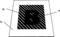
图1a是示出用粗线印刷的字母“B”并具有用较细的平行线环绕字母“B”的背景的防伪装置的平面图。Figure 1a is a plan view of an anti-counterfeiting device showing the letter "B" printed in bold lines and having a background surrounded by thinner parallel lines surrounding the letter "B".
图1b是可选的实施方式的平面图,其中用比背景厚的油墨涂层印刷字母“B”。Figure 1b is a plan view of an alternative embodiment in which the letter "B" is printed with a thicker ink coat than the background.
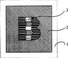
图2是本发明可选的实施方式的平面图,其中字母“B”以第一方向用粗平行线印刷,并且其中限定背景的较细平行线与粗平行印刷线成大约45度的差角。Figure 2 is a plan view of an alternative embodiment of the present invention, wherein the letter "B" is printed in a first direction with thick parallel lines, and wherein the thinner parallel lines defining the background are at a different angle of approximately 45 degrees from the thick parallel printed lines.
图3a是用于图2中图像的印刷板的横截面图。Figure 3a is a cross-sectional view of the printing plate used for the image in Figure 2 .
图3b是在施加磁场以取向薄片之前使用图3a的印刷板在衬底上印刷的油墨的横截面图。Figure 3b is a cross-sectional view of ink printed on a substrate using the printing plate of Figure 3a before a magnetic field is applied to orient the flakes.
图4是示出在施加磁场中的图3b的薄片取向的横截面图。Figure 4 is a cross-sectional view showing the orientation of the flakes of Figure 3b in an applied magnetic field.
图5是在施加磁场后图3b的图像的透视图。Figure 5 is a perspective view of the image of Figure 3b after application of a magnetic field.
图6是现有技术的翻转的横截面图(cross-sectional view of a flip-flop)。Figure 6 is a cross-sectional view of a flip-flop of the prior art.
图7和8是从不同角度看见的翻转的简化平面图。Figures 7 and 8 are simplified plan views of the flip seen from different angles.
图9是现有技术滚动条的横截面图,其仅示出一些取向的薄片。Figure 9 is a cross-sectional view of a prior art scroll bar showing only some orientations of the flakes.
图10是图9所示的滚动条的俯视图。FIG. 10 is a top view of the scroll bar shown in FIG. 9 .
具体实施方式Detailed ways
在本申请中,术语光学可变包括改变颜色改变、颜色切换、衍射或动态效应。颜色改变和切换效应是随视角或入射光角度的变化改变或切换颜色的效应。动态效果是那些其中观察者“似乎”看见图像移动的样子,或者其中在一个区域的颜色“似乎”与另一个区域的颜色进行切换。在具有动态效应的图像中,观察者似乎看见在仅展示颜色改变的均匀涂层中看不见的移动或深度。在动态图像中,薄片被磁性取向,使得它们不是全部被均匀地取向。由此,倾斜或旋转提供了移动或变化的错觉。In this application, the term optically variable includes changing color change, color switching, diffractive or dynamic effects. Color changing and switching effects are effects that change or switch colors with changes in viewing angle or angle of incident light. Motion effects are those in which the viewer "seems" to see the image move, or in which the color in one area "seems" to switch with the color in another area. In an image with a dynamic effect, the viewer appears to see movement or depth not seen in a uniform coating exhibiting only a change in color. In dynamic images, the flakes are magnetically oriented such that they are not all oriented uniformly. Thus, tilting or swiveling provides the illusion of movement or change.
此后使用的术语“可见的”指的是用肉眼可见的;即未放大。The term "visible" as used hereafter means visible with the unaided eye; ie without magnification.
此后使用的术语“线”包括直的或弯曲的实线、点线、虚线或曲线。The term "line" as used hereafter includes straight or curved solid lines, dotted lines, dashed lines or curved lines.
此后使用的术语“面积密度”指的是每单位面积的质量,定义为:ρA其中a、ρA=平均面积密度b、M=物体的总质量c、A=物体的总面积The term "area density" as used hereafter refers to mass per unit area and is defined as: ρA where a, ρA = average area density b, M = total mass of the object c, A = total area of the object
现在参考图1a,形成的防伪图像有支撑细线区域2的衬底1,其中通过丝网印刷、凹版工艺或优选凹雕印刷工艺施加平行的油墨线。区域2邻接或包围区域3,区域3是其中具有粗线的区域,在视觉上形成或占据字母B的空间。在无油墨的地方之间由间隙隔开的粗印刷线形成字母B的图像,其由区域2中细线的均匀背景包围。尽管在本发明的优选实施方式中,线被优选为连续实线,但点线也可用于形成所示图像。在这种情况下,优选较粗的线是实线,较细的线是点线或虚线,其中点之间的间隔很小,以至于被观察者看成是连续的实线。可以使用精细的丝网网孔,并可以选择性地堵住或遮蔽网孔以阻止油墨印刷。当然可以使用喷墨印刷机或任何公知的以改变线的粗度或面积密度施加光学效应油墨的方式来完成印刷。Referring now to Figure 1a, a security image is formed having a
在图2中示出类似的布置,然而在图2中,线不都是平行的。在图2中,字母B由粗的平行印刷线构成,其中背景由其间具有大于印刷线宽度的间隙或间隔的细印刷线构成。所以,背景区域3似乎好象由粗的白线和较细的黑线构成。然而明显的白线是区域2中的未印刷区。在本发明的优选实施方式中,细线的宽度和较宽的线显著不同,然而,印刷线的高度也不同。如图3所示,印刷板的区域2和3具有不同的深度,例如其中区域3的深度是区域2的两倍。因此当进行印刷时,区域3中的油墨具有区域2中油墨的大约两倍的高度。因此,在衬底的宽度和高度的两维中,细线更细。它是决定可察觉效应的特殊线的油墨的总体积。无论线是细线或宽线,都可以看见颜色改变或颜色切换,并且在一条线或多条线中要求更大量的油墨以察觉动态效应。A similar arrangement is shown in Figure 2, however in Figure 2 the lines are not all parallel. In Figure 2, the letter B is formed of thick parallel printed lines, where the background is formed of thin printed lines with gaps or spaces between them that are greater than the width of the printed lines. Therefore, the
除了字母B是光学可变的以外,图2中的字母B也以通过字母B的中间区域的滚动条的形式表现出动态的运动效应,它看起来像亮条。通过将图像相对于经由亮条的轴倾斜,亮条“似乎”随着图像在两个方向的倾斜而从右向左移动。这种动态特征是公知的,在美国公布的转让给JDS Uniphase公司的专利申请号20060198998、20060194040、20060097515和20050123755中已经描述,在此引证作为参考。In addition to the fact that the letter B is optically variable, the letter B in Figure 2 also exhibits a dynamic movement effect in the form of a scroll bar passing through the middle area of the letter B, which looks like a light bar. By tilting the image relative to the axis through the bright bar, the bright bar "appears" to move from right to left as the image is tilted in both directions. This dynamic feature is well known and described in US Published Patent Application Nos. 20060198998, 20060194040, 20060097515 and 20050123755 assigned to JDS Uniphase Corporation, incorporated herein by reference.
光学效应薄片可以在场中取向,优选在磁场中以形成许多不同类型的动态效应。更简单和容易理解的动态效应包括滚动条和翻转(flip-flop)。Optical effect flakes can be oriented in a field, preferably a magnetic field, to create many different types of dynamic effects. Simpler and easier-to-understand dynamic effects include scroll bars and flip-flops.
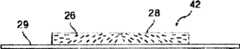
在图6中示出了翻转,其示出了第一印刷部分22和第二印刷部分24,这两个部分由过渡区25分开。由载体28例如油墨载体或油漆载体包围的颜料薄片26是平行于第一部分中的第一面取向,第二部分中的颜料薄片26’是平行于第二面取向。这些薄片在横截面图中表示为短线。薄片是磁性薄片,即可以使用磁场取向的颜料薄片。它们可以或不可以保持剩磁。在每部分中不是所有的薄片都准确地彼此平行或准确地平行于各自的取向面,但总体结果基本上如图所示。这些图未按比例画出。典型的薄片可以是20微米宽,大约1微米厚,因此附图仅是示意性的。将图像印刷或油漆在衬底29上,例如纸、塑料膜、层板、卡片材料或其它表面。为了讨论方便,术语“印刷”通常用于描述将载体中的颜料施加到表面,其可以包括其它的技术,包括其它可以称为“油漆”的技术。A reversal is shown in FIG. 6 , which shows a first printed
通常,垂直于薄片平面看的薄片是亮的,而沿平面边缘看的薄片是暗的。例如,来自照射源30的光从第一区域的薄片被反射到观察者32。如果图像以箭头34表示的方向倾斜,那么在端部将看见第一区域22中的薄片,而光将从第二区域24中的薄片反射。所以,在第一观察位置上,第一区域是亮的,第二区域是暗的,而在第二观察位置上,区域将是翻转的,第一区域是暗的,第二区域是亮的。这提供了非常显著的视觉效果。同样,如果颜料薄片是颜色变化的,那么一部分看起来是第一颜色,另一部分是另一种颜色。Typically, a flake viewed perpendicular to the plane of the flake is bright, while a flake viewed along the edge of the plane is dark. For example, light from
通常载体是透明的,即可以是清澈的也可以是着色的,通常薄片具有相当的反射性。例如,载体可以着绿色,薄片可以包括金属层,例如铝、金、镍、铂或金属合金的薄膜,或者是金属薄片,例如镍或合金薄片。从金属层反射的光通过染成绿色的载体可以呈现亮绿色,而在端部看到的薄片的另一部分将呈现暗绿或另一颜色。如果薄片在清澈的载体中仅是金属薄片,那么一部分图像可以呈现亮金属色,而另一部分是暗的。作为选择,可以用染色的层涂覆金属薄片,或者薄片可以包括光干涉结构,例如吸收器-间隔器-反射器法布里-珀罗(Fabry-Perot)型结构。而且,可在反射表面上形成衍射结构,以便提供增强的和附加的防伪特征。衍射结构可以具有在反射表面中形成的简单的线性光栅,或者可以具有更复杂的预定图案,该图案仅当被放大时可以辨别,但当观看时其具有总体效果。通过提供衍射反射层,通过简单地旋转纸张、钞票或具有衍射薄片的结构,观察者就可以看见颜色变化或亮度变化。Usually the support is transparent, either clear or tinted, and usually the flakes are quite reflective. For example, the support may be colored green and the flakes may comprise metal layers, such as thin films of aluminum, gold, nickel, platinum, or metal alloys, or metal flakes, such as nickel or alloy flakes. Light reflected from the metal layer can appear bright green through the green-dyed carrier, while another part of the flake seen at the end will appear dark green or another color. If the flakes are just metallic flakes in a clear carrier, then part of the image can be bright metallic and another part dark. Alternatively, the metal flakes may be coated with a dyed layer, or the flakes may comprise light interference structures, such as absorber-spacer-reflector Fabry-Perot type structures. Furthermore, diffractive structures can be formed on the reflective surface to provide enhanced and additional security features. The diffractive structure may have a simple linear grating formed in a reflective surface, or may have a more complex predetermined pattern that is only discernible when magnified, but which has an overall effect when viewed. By providing a diffractive reflective layer, color changes or brightness changes can be seen by the observer by simply rotating the paper, banknote or structure with diffractive flakes.
在美国专利No.6692830中具体描述了制造衍射薄片的工艺。美国专利申请公开号20030190473描述了彩色衍射薄片的制造。生产磁性衍射薄片类似于生产衍射薄片,然而其中的一层要求是磁性的。实际上,可以利用夹在铝层之间掩盖磁性层;以这种方式,磁层基本上没有影响薄片的光学设计;或者同时作为吸收器、电介质或反射器对薄膜干涉光学设计起到光学上的积极作用。The process of making diffractive flakes is described in detail in US Patent No. 6,692,830. US Patent Application Publication No. 20030190473 describes the fabrication of colored diffractive flakes. Producing magnetic diffractive flakes is similar to producing diffractive flakes, however one of the layers is required to be magnetic. In fact, it is possible to mask the magnetic layer by being sandwiched between the aluminum layers; in this way, the magnetic layer does not substantially affect the optical design of the flake; positive effect.
图7是在第一选择视角、在衬底29上的印刷图像20的简化平面图,它可以是例如钞票或股票证书的文件。印刷图像可以作为防伪和/或鉴定特征,因为错觉图像不能影印,也不能利用常规印刷技术制造。第一部分22是亮的,第二部分24是暗的。剖面线40表示图1a所示的横截面。第一部分和第二部分之间的过渡区25是相对陡峭的(sharp)。例如文件可以是钞票、股票证书或其它贵重的印刷材料。Figure 7 is a simplified plan view of a printed
图8是在第二选择视角、在衬底29上的印刷图像20的简化平面图,该第二选择视角通过将图像相对于视点倾斜而获得。现在第一部分22是暗的,而第二部分24是亮的。图像翻转的倾斜角取决于在图像的不同部分中的薄片的取向面之间的角度。在一个例子中,当倾斜大约15度时图像从亮突然变暗。Figure 8 is a simplified plan view of a printed
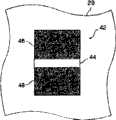
图9是运动光学装置的印刷图像42的简化横截面图,出于讨论目的,根据本发明的另一个实施方式,它将被定义为微观排列的柱状菲涅耳反射器或称为“滚动条”。图像包括颜料薄片26,其由在衬底29上印刷的透明载体28包围。颜料薄片以曲线方式排列。随着翻转,将光从颜料薄片的面反射到观察者的滚动条的区比没有直接将光反射到观察者的区更亮。该图像具有菲涅耳聚焦线,它看起来非常象光带或条,当图像相对于视角(假设固定照射源)倾斜时它们看起来像沿图像移动(“滚动”)。9 is a simplified cross-sectional view of a printed
图10是滚动条图像42在第一视角的简化平面图。亮条44出现在两个对比区域46、48之间的图像中的第一位置。随着图像倾斜(在固定视角和固定照射下),颜料薄片的取向产生条向图像下面“滚动”的错觉。在另一方向倾斜图像使得条看起来像以相反方向(向上)滚动。FIG. 10 is a simplified plan view of the
条也可以看起来具有深度,即使它印刷在平面中。实际的深度可能看起来显著大于印刷图像的物理厚度。发生这种现象的原因是条是柱状凸面菲涅耳反射器的虚焦线,其位于反射器平面下面的焦距。选择图案中的薄片的倾斜可反射光以提供深度或“3D”的错觉,如它通常被称作的。通过在纸或其它衬底后面放置一定形状的磁铁,可以获得三维效果,在所述衬底上具有在液体载体中印刷在衬底上的磁性颜料薄片。薄片沿磁场线排列并在固定(例如干燥或固化)载体后产生3D图像。随着倾斜,图像经常看起来会移动;因此可以形成动态3D图像。A bar can also appear to have depth even though it is printed in a flat surface. Actual depth may appear to be significantly greater than the physical thickness of the printed image. This phenomenon occurs because the bar is the imaginary focal line of the cylindrical convex Fresnel reflector, which lies at the focal distance below the plane of the reflector. The inclination of the flakes in the chosen pattern can reflect light to provide the illusion of depth or "3D," as it is commonly called. The three-dimensional effect can be achieved by placing a shaped magnet behind a paper or other substrate with magnetic pigment flakes printed on the substrate in a liquid carrier. The flakes align along the magnetic field lines and produce a 3D image after fixing (eg, drying or curing) the support. With tilting, the image often appears to move; thus dynamic 3D images can be formed.
可以用磁性颜料薄片,即可以使用磁场取向的颜料薄片印刷翻转和滚动条。印刷的翻转型图像可提供带两个不同区域的光学可变装置,所述的两个不同区域可以使用单个印刷步骤和使用单个油墨配方获得。滚动条型图像可提供光学可变装置,该装置具有随着图像倾斜看起来可移动的对比带,类似于称为虎睛石的次珍贵宝石。这些印刷的图像相当引人注目,错觉特征不能被影印。这些图像可以用于钞票、股票证书、软件文件、安全密封和类似的物体,作为认证和/或防伪装置。对于大量印刷文件特别需要它们,例如钞票、包装和标签,因为它们可以在高速印刷操作中印刷,如下所述。Flip and scroll bars can be printed with magnetic pigment flakes, ie pigment flakes oriented using a magnetic field. A printed flip image can provide an optically variable device with two distinct regions that can be obtained using a single printing step and using a single ink formulation. A scroll bar image provides an optically variable device with contrasting bands that appear to move as the image is tilted, similar to a semi-precious gemstone called a tiger's eye. These printed images are quite striking and the illusion features cannot be photocopied. These images can be used on banknotes, stock certificates, software files, security seals and similar objects as authentication and/or anti-counterfeiting devices. They are particularly required for high volume printed documents such as banknotes, packaging and labels, as they can be printed in high speed printing operations, as described below.
尽管此前描述的本发明的实施方式主要集中在凹雕上,但也可以使用根据本发明施加油墨的其它方法。例如可以利用凹版印刷、丝网印刷、柔版印刷(flexo)、凸版印刷以及其它施加油墨的公知方法。所要求的是以不同厚度的线和不同高度的线将油墨施加到较大区域内的不同区域;将线的深度和宽度将变化以提供对比区域。Although the embodiments of the invention described above have focused primarily on intaglio, other methods of applying ink in accordance with the invention may also be used. For example gravure printing, screen printing, flexo printing (flexo), letterpress printing and other known methods of applying ink can be utilized. What is required is to apply ink to different areas within a larger area with lines of different thicknesses and lines of different heights; the depth and width of the lines will vary to provide contrasting areas.
对于凹雕或凹版印刷,最简单的方法是在第一区域雕刻比在对比的第二区域更大的深度。For intaglio or gravure printing, it is easiest to engrave to a greater depth in a first area than in a contrasting second area.
对于柔版印刷,使用点网屏(dot screen)或半色调(half-tone)技术获得油墨厚度的变化,其中与较高面积范围相等的较大点尺寸被用在需要较大油墨厚度的区域中。在丝网印刷的情况下,其中使用具有均匀开口面积的物理网,以不同的方式获得高度上的变化。在丝网印刷中,通过遮蔽丝网本身来阻塞油墨穿过丝网而在两个或多个区域中获得不同的油墨高度。通过丝网的选择性遮蔽,第一区域未阻止油墨穿过,因此在衬底具有较高的油墨高度,而第二区域穿过的油墨较小,因此由于以预定的方式遮蔽丝网而具有较低的油墨高度。对于其它的印刷技术,例如凸版印刷和胶印,可以使用类似的方案,其中通过改变油墨穿过量、利用在板或传送介质上的点尺寸或油墨百分比范围来获得较大或较小油墨厚度的面积。For flexographic printing, variations in ink thickness are obtained using dot screen or half-tone techniques, where larger dot sizes equal to higher area ranges are used in areas requiring greater ink thickness middle. In the case of screen printing, where a physical screen with uniform open area is used, the variation in height is obtained in a different way. In screen printing, different ink levels are obtained in two or more areas by masking the screen itself to block ink from passing through the screen. By selective shading of the screen, the first area does not prevent ink from passing through and thus has a higher ink height at the substrate, while the second area passes less ink and thus has a higher ink height due to masking the screen in a predetermined manner. Lower ink height. For other printing techniques, such as letterpress and offset printing, a similar scheme can be used where areas of greater or lesser ink thickness are obtained by varying the ink penetration, using a range of dot sizes or ink percentages on the plate or transfer medium .
在本发明的优选实施方式中,在第一区域一个单位长度的线中的油墨重量至少是在第二区域相同长度的线中的油墨重量的三倍。优选第一区域由多个平行的宽度为WL的印刷线构成,第二区域由多个平行的宽度小于WL/2的印刷线构成,然而在一些情况下,第二区域中线的宽度可以比第一区域中线的宽度的小几个数量级。不管根据两个区域中的油墨的面积密度所选择的确切比率如何,所要求的比率是这样的:其中窄线没有可见的磁性或动态效应,而较宽和/或较高的线展现可见的动态效应。In a preferred embodiment of the invention, the weight of ink in a line of one unit length in the first region is at least three times the weight of ink in a line of the same length in the second region. Preferably, the first region consists of a plurality of parallel printed lines with a width ofWL , and the second region consists of a plurality of parallel printed lines with a width smaller thanWL /2, however, in some cases, the width of the lines in the second region can be is several orders of magnitude smaller than the width of the line in the first region. Regardless of the exact ratio chosen based on the areal densities of the inks in the two regions, the desired ratio is one in which narrow lines exhibit no visible magnetic or dynamic effects, while wider and/or taller lines exhibit visible dynamic effect.
图1b示出了本发明的可选实施方式,其中将示为3b的字母“B”及其背景2b以相同宽度的线印刷在衬底1b上。然而,“B”是在大大厚于形成背景的油墨的油墨中印刷的。用印刷板(凹雕)或具有雕刻坡度的凹版柱体印刷图像。如图3b所示,形成B的雕刻深于形成背景2b的雕刻。结果,背景2b的线是浅的,并包含少量的颜料。相反,形成B的线3b更厚,并在每单位衬底面积中包含较多的颜料颗粒,如图3b所示。Figure 1b shows an alternative embodiment of the invention, wherein the letter "B" shown as 3b and its
图4示出在施加磁场5b中磁性颜料的颗粒4b的取向。由于被分散在液态油墨载体中并置于弯曲磁场中,颗粒4b在油墨载体中旋转,直到它们沿所示的磁力线取向。旋转过程发生在这些印刷区域,其中对于它油墨载体具有足够的空间。通常这些空间是用深的雕刻(engraving)印刷油墨的地方。背景的浅线没有足够的地方用于颗粒旋转并沿线取向。它们几乎保持平坦。结果,B的图像获得如图5所示的动态光学效果,而背景不具有此效果。Figure 4 shows the orientation of the
在没在图中示出的可选实施方式中,用固态无衬涂层印刷字母“B”,由此一条粗线形成字母“B”。所以,字母“B”没有由平行线组成,然而,背景具有和其它实施方式相同的效应。In an alternative embodiment not shown in the figures, the letter "B" is printed with a solid liner-free coating whereby a thick line forms the letter "B". Therefore, the letter "B" is not composed of parallel lines, however, the background has the same effect as the other embodiments.
在不脱离本发明范围的情况下可以预见本发明大量的其它实施方式。例如在未示出的实施方式中,将第一细线涂层施加到透光衬底的底部,并且其中表示字母B的较粗的线的涂层位于衬底的顶部。细线涂层可以方便地覆盖整个底部以方便印刷。宽的“B”印刷在透光衬底的另一侧上。Numerous other embodiments of the invention can be envisioned without departing from the scope of the invention. For example in an embodiment not shown, a first thin line coating is applied to the bottom of the light transmissive substrate, and wherein the coating of the thicker line representing the letter B is on top of the substrate. Fine line coating conveniently covers the entire bottom for easy printing. A broad "B" is printed on the other side of the light transmissive substrate.
Claims (27)
Applications Claiming Priority (2)
| Application Number | Priority Date | Filing Date | Title |
|---|---|---|---|
| US77708606P | 2006-02-27 | 2006-02-27 | |
| US60/777,086 | 2006-02-27 |
Publications (2)
| Publication Number | Publication Date |
|---|---|
| CN101028781A CN101028781A (en) | 2007-09-05 |
| CN101028781Btrue CN101028781B (en) | 2013-07-24 |
Family
ID=37908397
Family Applications (1)
| Application Number | Title | Priority Date | Filing Date |
|---|---|---|---|
| CN2007100796105AActiveCN101028781B (en) | 2006-02-27 | 2007-02-27 | Security device formed by printing with special effect inks |
Country Status (10)
| Country | Link |
|---|---|
| US (3) | US10343436B2 (en) |
| EP (1) | EP1826731B1 (en) |
| JP (1) | JP5329768B2 (en) |
| KR (1) | KR101366589B1 (en) |
| CN (1) | CN101028781B (en) |
| AU (1) | AU2007200766B2 (en) |
| CA (1) | CA2578919C (en) |
| PL (1) | PL1826731T3 (en) |
| SG (2) | SG135136A1 (en) |
| TW (1) | TWI419799B (en) |
Families Citing this family (58)
| Publication number | Priority date | Publication date | Assignee | Title |
|---|---|---|---|---|
| US7364085B2 (en)* | 2003-09-30 | 2008-04-29 | Digimarc Corporation | Identification document with printing that creates moving and three dimensional image effects with pulsed illumination |
| US10343436B2 (en) | 2006-02-27 | 2019-07-09 | Viavi Solutions Inc. | Security device formed by printing with special effect inks |
| KR100946801B1 (en)* | 2006-08-25 | 2010-03-11 | 주식회사 비비텍 | Projector front screen with pattern |
| US7940463B2 (en)* | 2008-04-15 | 2011-05-10 | Qualcomm Mems Technologies, Inc. | Fabricating and using hidden features in an image |
| DE112010003640T5 (en)* | 2009-09-14 | 2012-08-02 | ACCO Brands Corporation | Laminating material and method of manufacture |
| MX2013006604A (en)* | 2010-12-21 | 2013-07-29 | Merck Patent Gmbh | Coloured magnetizable security element. |
| KR101119701B1 (en)* | 2010-12-31 | 2012-03-20 | 한국조폐공사 | Continued color changeable security thread comprising micro optical structure and a method of preparing the same |
| AU2011100778B4 (en)* | 2011-06-29 | 2011-10-13 | Ccl Secure Pty Ltd | Improvements in security devices incorporating colour shifting inks |
| KR101238198B1 (en)* | 2012-09-14 | 2013-02-28 | 한국조폐공사 | Magnetic security feature having 3d moving hidden image effect and the printing method thereof |
| AU2013314269B2 (en)* | 2012-09-17 | 2017-07-06 | Basf Se | Security elements and method for their manufacture |
| US10051156B2 (en) | 2012-11-07 | 2018-08-14 | Xerox Corporation | System and method for producing correlation and gloss mark images |
| EP2925184A4 (en)* | 2012-11-29 | 2016-12-07 | Sicpa Holding Sa | Optical variable effects as security feature for embossed metal coins |
| GB201222813D0 (en)* | 2012-12-18 | 2013-01-30 | Rue De Int Ltd | Security device |
| CA2911758C (en)* | 2013-05-09 | 2021-02-16 | Idit Technologies Corp. | Nanostructure array diffractive optics for motion and animation display |
| US9106847B2 (en)* | 2013-09-18 | 2015-08-11 | Xerox Corporation | System and method for producing color shifting or gloss effect and recording medium with color shifting or gloss effect |
| US9083896B2 (en) | 2013-09-18 | 2015-07-14 | Xerox Corporation | System and method for producing color shifting or gloss effect and recording medium with color shifting or gloss effect |
| US9088736B2 (en)* | 2013-09-18 | 2015-07-21 | Xerox Corporation | System and method for producing color shifting or gloss effect and recording medium with color shifting or gloss effect |
| US9118870B2 (en) | 2013-09-18 | 2015-08-25 | Xerox Corporation | System and method for producing color shifting or gloss effect and recording medium with color shifting or gloss effect |
| US9100592B2 (en)* | 2013-09-18 | 2015-08-04 | Xerox Corporation | System and method for producing color shifting or gloss effect and recording medium with color shifting or gloss effect |
| US9193201B2 (en) | 2013-09-18 | 2015-11-24 | Xerox Corporation | System and method for producing color shifting or gloss effect and recording medium with color shifting or gloss effect |
| US9319557B2 (en) | 2013-09-18 | 2016-04-19 | Xerox Corporation | System and method for producing color shifting or gloss effect and recording medium with color shifting or gloss effect |
| JP6303413B2 (en)* | 2013-11-11 | 2018-04-04 | カシオ計算機株式会社 | Nail printing apparatus and printing method for nail printing apparatus |
| CN104260572B (en)* | 2014-09-26 | 2016-11-23 | 惠州市华阳光学技术有限公司 | A kind of magnetic orientation pattern and preparation method thereof |
| JP6821324B2 (en)* | 2015-05-22 | 2021-01-27 | キヤノン株式会社 | Image processing equipment, image processing methods and programs |
| DE102015010332A1 (en)* | 2015-08-07 | 2017-02-09 | Giesecke & Devrient Gmbh | Printed security element |
| CN107848321A (en)* | 2015-08-18 | 2018-03-27 | Ccl证券私人有限公司 | Optical devices with optical array |
| US9538041B1 (en) | 2015-11-25 | 2017-01-03 | Xerox Corporation | System and method for producing seesaw gloss effect and recording medium with seesaw gloss effect |
| US9516190B1 (en) | 2015-11-25 | 2016-12-06 | Xerox Corporation | System and method for producing seesaw gloss effect and recording medium with seesaw gloss effect |
| US9756212B2 (en) | 2015-11-25 | 2017-09-05 | Xerox Corporation | System and method for producing seesaw gloss effect and recording medium with seesaw gloss effect |
| US9674392B1 (en) | 2015-11-25 | 2017-06-06 | Xerox Corporation | System and method for producing seesaw gloss effect and recording medium with seesaw gloss effect |
| US9674391B1 (en) | 2015-11-25 | 2017-06-06 | Xerox Corporation | System and method for producing seesaw gloss effect and recording medium with seesaw gloss effect |
| TWI611372B (en)* | 2016-03-02 | 2018-01-11 | China Engraving&Printing Works | Method for arranging heterogeneous anti-counterfeiting dots and virtual gray balance by image partitioning |
| US9614995B1 (en) | 2016-05-02 | 2017-04-04 | Xerox Corporation | System and method for generating vector based correlation marks and vector based gloss effect image patterns for rendering on a recording medium |
| US9661186B1 (en) | 2016-06-02 | 2017-05-23 | Xerox Corporation | System and method for rendering gloss effect image patterns on a recording medium |
| US9781294B1 (en) | 2016-08-09 | 2017-10-03 | Xerox Corporation | System and method for rendering micro gloss effect image patterns on a recording medium |
| MX394581B (en) | 2016-08-31 | 2025-03-24 | Viavi Solutions Inc | ITEM WITH ANGLED REFLECTIVE SEGMENTS. |
| KR102255329B1 (en) | 2016-08-31 | 2021-05-26 | 비아비 솔루션즈 아이엔씨. | How to orient magneto-orientable flakes |
| US10248637B2 (en)* | 2016-10-11 | 2019-04-02 | Microsoft Technology Licensing, Llc | High perceptability ink effects |
| US10357991B2 (en)* | 2016-12-19 | 2019-07-23 | Viavi Solutions Inc. | Security ink based security feature |
| DE102017128258A1 (en)* | 2017-09-14 | 2019-03-14 | Schattdecor Ag | Method of manufacturing and protecting against inadmissible duplication of decor paper or films |
| US11102372B2 (en)* | 2017-09-15 | 2021-08-24 | Dai Nippon Printing Co., Ltd. | Information recording body, medium and printed product |
| CN108681765A (en)* | 2018-02-15 | 2018-10-19 | 海南亚元防伪技术研究所(普通合伙) | Transfinite narrow slit method for anti-counterfeit and product |
| DE102018004434A1 (en)* | 2018-06-05 | 2019-12-05 | Giesecke+Devrient Currency Technology Gmbh | Effect pigment, printing ink, security element, data carrier and manufacturing process |
| KR102726829B1 (en) | 2018-07-30 | 2024-11-07 | 시크파 홀딩 에스에이 | Assembly and method for producing an optical effect layer comprising oriented magnetic or magnetizable pigment particles |
| US10953646B2 (en) | 2018-10-26 | 2021-03-23 | ACCO Brands Corporation | Laminating system with coded film cartridge |
| CN111776471B (en)* | 2019-08-16 | 2022-07-12 | 西安印钞有限公司 | A landscape change anti-counterfeiting structure, anti-counterfeiting plastic seal and preparation method |
| CN110796944B (en)* | 2019-11-22 | 2025-05-09 | 擎雷(上海)防伪科技有限公司 | A structural optically variable anti-counterfeiting label |
| DE102020000030A1 (en)* | 2020-01-03 | 2021-07-08 | Giesecke+Devrient Currency Technology Gmbh | Optically variable security element |
| AR123351A1 (en)* | 2020-09-02 | 2022-11-23 | Sicpa Holding Sa | SECURITY DOCUMENTS OR ARTICLES INCLUDING OPTICAL EFFECT COATINGS COMPRISING MAGNETIC OR MAGNETIZABLE PIGMENT PARTICLES AND METHODS FOR PRODUCING SUCH OPTICAL EFFECT LAYERS |
| CN112537128A (en)* | 2020-12-11 | 2021-03-23 | 温州职业技术学院 | Printing equipment for printing multilayer composite anti-counterfeit label |
| JP7637361B2 (en) | 2021-03-29 | 2025-02-28 | 独立行政法人 国立印刷局 | Printed materials and their creation methods |
| DE102021002333A1 (en)* | 2021-05-03 | 2022-11-03 | Giesecke+Devrient Currency Technology Gmbh | OPTICALLY VARIABLE SECURITY ELEMENT AND VALUABLE DOCUMENT WITH THE OPTICALLY VARIABLE SECURITY ELEMENT |
| KR102333137B1 (en)* | 2021-06-08 | 2021-12-01 | 박정훈 | Multi Printing structure and printing sheet having the same structure |
| KR20240019318A (en)* | 2021-06-11 | 2024-02-14 | 시크파 홀딩 에스에이 | Optical effect layer containing magnetic or magnetisable pigment particles and method of manufacturing the optical effect layer |
| US12083813B2 (en) | 2021-10-21 | 2024-09-10 | Viavi Solutions Inc. | Printing machine and fixed patterned plate |
| US20230128872A1 (en)* | 2021-10-21 | 2023-04-27 | Viavi Solutions Inc. | A fixed color image including pixels and method of making the color image |
| US20230153557A1 (en)* | 2021-11-12 | 2023-05-18 | Viavi Solutions Inc. | Article including an image including two or more types of pixels |
| WO2025181133A1 (en)* | 2024-02-27 | 2025-09-04 | Sicpa Holding Sa | Processes for producing optical effects layers |
Citations (5)
| Publication number | Priority date | Publication date | Assignee | Title |
|---|---|---|---|---|
| US5722693A (en)* | 1996-10-03 | 1998-03-03 | Wicker; Kenneth M. | Embossed document protection methods and products |
| US6183018B1 (en)* | 1995-11-27 | 2001-02-06 | Giesecke & Devrient Gmbh | Data carrier with optically variable color |
| US6357800B1 (en)* | 1996-09-03 | 2002-03-19 | Giesecke & Devrient Gmbh | Document with a moire-generating raster structure |
| EP1353197A2 (en)* | 2002-04-05 | 2003-10-15 | Flexible Products Inc. | Chromatic diffractive pigments and foils |
| US6902807B1 (en)* | 2002-09-13 | 2005-06-07 | Flex Products, Inc. | Alignable diffractive pigment flakes |
Family Cites Families (104)
| Publication number | Priority date | Publication date | Assignee | Title |
|---|---|---|---|---|
| US1299484A (en)* | 1915-06-18 | 1919-04-08 | Homer Lee | Intaglio print. |
| US2570856A (en) | 1947-03-25 | 1951-10-09 | Du Pont | Process for obtaining pigmented films |
| US3123490A (en) | 1961-05-04 | 1964-03-03 | Nacreous pigment and method for preparing same | |
| DE1253730B (en) | 1964-06-05 | 1967-11-09 | Agfa Ag | Process for the complete or partial printing of a printing form and rotary duplicator to carry out the process |
| FR1440147A (en) | 1965-04-15 | 1966-05-27 | Tefal Sa | A method of decorating, in the mass, a translucent plastic material |
| US3627580A (en) | 1969-02-24 | 1971-12-14 | Eastman Kodak Co | Manufacture of magnetically sensitized webs |
| US3633720A (en) | 1969-09-25 | 1972-01-11 | Honeywell Inc | Alphanumeric printing device employing magnetically positionable particles |
| US3845499A (en) | 1969-09-25 | 1974-10-29 | Honeywell Inc | Apparatus for orienting magnetic particles having a fixed and varying magnetic field component |
| US3610721A (en) | 1969-10-29 | 1971-10-05 | Du Pont | Magnetic holograms |
| US3853676A (en) | 1970-07-30 | 1974-12-10 | Du Pont | Reference points on films containing curved configurations of magnetically oriented pigment |
| US3676273A (en) | 1970-07-30 | 1972-07-11 | Du Pont | Films containing superimposed curved configurations of magnetically orientated pigment |
| IT938725B (en) | 1970-11-07 | 1973-02-10 | Magnetfab Bonn Gmbh | PROCEDURE AND DEVICE FOR EIGHT BLACK DRAWINGS IN SURFACE LAYERS BY MEANS OF MAGNETIC FIELDS |
| US3790407A (en) | 1970-12-28 | 1974-02-05 | Ibm | Recording media and method of making |
| US4033059A (en)* | 1972-07-06 | 1977-07-05 | American Bank Note Company | Documents of value including intaglio printed transitory images |
| US3873975A (en) | 1973-05-02 | 1975-03-25 | Minnesota Mining & Mfg | System and method for authenticating and interrogating a magnetic record medium |
| GB1510105A (en) | 1974-04-17 | 1978-05-10 | Emi Ltd | Printing |
| DE2520581C3 (en) | 1975-05-09 | 1980-09-04 | Kienzle Apparate Gmbh, 7730 Villingen-Schwenningen | Arrangement for erasable recording of measured quantities |
| US4011009A (en) | 1975-05-27 | 1977-03-08 | Xerox Corporation | Reflection diffraction grating having a controllable blaze angle |
| US4099838A (en) | 1976-06-07 | 1978-07-11 | Minnesota Mining And Manufacturing Company | Reflective sheet material |
| JPS602960Y2 (en)* | 1977-08-12 | 1985-01-26 | 凸版印刷株式会社 | PIN identification set using lines |
| FR2408890A1 (en) | 1977-11-10 | 1979-06-08 | Transac Dev Transact Automat | METHOD AND DEVICE FOR ORIENTATION AND FIXATION IN A DETERMINED DIRECTION OF MAGNETIC PARTICLES CONTAINED IN A POLYMERISABLE INK |
| US4271782A (en) | 1978-06-05 | 1981-06-09 | International Business Machines Corporation | Apparatus for disorienting magnetic particles |
| US4197363A (en) | 1978-10-26 | 1980-04-08 | Ford Motor Company | Seal for sodium sulfur battery |
| US5766738A (en)* | 1979-12-28 | 1998-06-16 | Flex Products, Inc. | Paired optically variable article with paired optically variable structures and ink, paint and foil incorporating the same and method |
| US4398798A (en) | 1980-12-18 | 1983-08-16 | Sperry Corporation | Image rotating diffraction grating |
| IT1194185B (en) | 1983-04-01 | 1988-09-14 | Schiapparelli Farma | COMPOSITION FOR ACNE TREATMENT |
| CH662989A5 (en)* | 1983-11-16 | 1987-11-13 | De La Rue Giori Sa | VALUE PAPER. |
| US4543551A (en) | 1984-07-02 | 1985-09-24 | Polaroid Corporation | Apparatus for orienting magnetic particles in recording media |
| US4715623A (en)* | 1984-09-28 | 1987-12-29 | American Bank Note Company | Documents having a revealable concealed identifier and the method of making such documents |
| US4788116A (en) | 1986-03-31 | 1988-11-29 | Xerox Corporation | Full color images using multiple diffraction gratings and masking techniques |
| DE3617430A1 (en) | 1986-05-23 | 1987-11-26 | Merck Patent Gmbh | PEARL PIGMENT |
| JPH0694543B2 (en) | 1987-01-09 | 1994-11-24 | 三菱自動車工業株式会社 | Paint |
| WO1988007214A1 (en) | 1987-03-10 | 1988-09-22 | Precis (549) Limited | Light reflective materials |
| JP2514828B2 (en) | 1988-01-18 | 1996-07-10 | 富士写真フイルム株式会社 | Method of manufacturing magnetic recording medium |
| US4838648A (en) | 1988-05-03 | 1989-06-13 | Optical Coating Laboratory, Inc. | Thin film structure having magnetic and color shifting properties |
| JPH0298811A (en) | 1988-10-05 | 1990-04-11 | Fuji Photo Film Co Ltd | Magnetic recording medium |
| US5192611A (en) | 1989-03-03 | 1993-03-09 | Kansai Paint Co., Ltd. | Patterned film forming laminated sheet |
| US5079058A (en) | 1989-03-03 | 1992-01-07 | Kansai Paint Co., Ltd. | Patterned film forming laminated sheet |
| JPH02121264U (en)* | 1989-03-13 | 1990-10-02 | ||
| EP0406667B1 (en) | 1989-06-27 | 1995-01-11 | Nippon Paint Co., Ltd. | Forming method of patterned coating |
| JPH0353970A (en)* | 1989-07-21 | 1991-03-07 | Ookurashiyou Insatsu Kyokucho | Intaglio print and printing method thereof |
| DE3938055A1 (en) | 1989-11-16 | 1991-05-23 | Merck Patent Gmbh | MATERIALS COATED WITH PLAIN-SHAPED PIGMENTS |
| US5177344A (en) | 1990-10-05 | 1993-01-05 | Rand Mcnally & Company | Method and appparatus for enhancing a randomly varying security characteristic |
| EP0556449B1 (en) | 1992-02-21 | 1997-03-26 | Hashimoto Forming Industry Co., Ltd. | Painting with magnetically formed pattern and painted product with magnetically formed pattern |
| DE4212290C2 (en) | 1992-02-29 | 1996-08-01 | Kurz Leonhard Fa | value document |
| EP0565870B1 (en) | 1992-03-13 | 1996-07-17 | Fuji Photo Film Co., Ltd. | Magnetic recording medium and method for producing the same |
| US5672410A (en) | 1992-05-11 | 1997-09-30 | Avery Dennison Corporation | Embossed metallic leafing pigments |
| US5991078A (en) | 1992-08-19 | 1999-11-23 | Dai Nippon Printing Co., Ltd. | Display medium employing diffraction grating and method of producing diffraction grating assembly |
| JP2655551B2 (en) | 1992-09-09 | 1997-09-24 | 工業技術院長 | Fine surface shape creation method |
| DE69432251T2 (en) | 1993-04-06 | 2004-01-15 | Commw Scient Ind Res Org | OPTICAL DATA ELEMENT |
| AU676603B2 (en) | 1993-07-16 | 1997-03-13 | Luckoff Display Corporation | Diffractive display utilizing reflective or transmissive light yielding single pixel full color capability |
| US6033782A (en) | 1993-08-13 | 2000-03-07 | General Atomics | Low volume lightweight magnetodielectric materials |
| EP0644508B1 (en) | 1993-08-31 | 1999-12-22 | Control Module, Inc. | Secure optical identification method and means |
| DE4335308C2 (en) | 1993-10-16 | 1995-12-14 | Daimler Benz Ag | Identification of vehicles to make theft and / or unauthorized sale more difficult |
| US5415950A (en) | 1993-11-08 | 1995-05-16 | E. I. Du Pont De Nemours And Company | Holographic flake pigment |
| US5424119A (en) | 1994-02-04 | 1995-06-13 | Flex Products, Inc. | Polymeric sheet having oriented multilayer interference thin film flakes therein, product using the same and method |
| AU699124B2 (en) | 1994-11-01 | 1998-11-26 | De La Rue Giori S.A. | Method of generating a security design with the aid of electronic means |
| DE4439455A1 (en) | 1994-11-04 | 1996-05-09 | Basf Ag | Process for the production of coatings with three-dimensional optical effects |
| GB9524862D0 (en) | 1995-12-06 | 1996-02-07 | The Technology Partnership Plc | Colour diffractive structure |
| AUPO728397A0 (en) | 1997-06-11 | 1997-07-03 | Securency Pty Ltd | Security document including a magnetic watermark and method of production thereof |
| US6103361A (en) | 1997-09-08 | 2000-08-15 | E. I. Du Pont De Nemours And Company | Patterned release finish |
| US6168100B1 (en) | 1997-10-23 | 2001-01-02 | Toyota Jidosha Kabushiki Kaisha | Method for producing embossed metallic flakelets |
| US6549131B1 (en) | 1999-10-07 | 2003-04-15 | Crane & Co., Inc. | Security device with foil camouflaged magnetic regions and methods of making same |
| EP0953937A1 (en) | 1998-04-30 | 1999-11-03 | Securency Pty. Ltd. | Security element to prevent counterfeiting of value documents |
| DK0978373T3 (en) | 1998-08-06 | 2011-11-28 | Sicpa Holding Sa | Inorganic film for the production of pigments |
| US6576155B1 (en) | 1998-11-10 | 2003-06-10 | Biocrystal, Ltd. | Fluorescent ink compositions comprising functionalized fluorescent nanocrystals |
| US6643001B1 (en) | 1998-11-20 | 2003-11-04 | Revco, Inc. | Patterned platelets |
| US6692031B2 (en) | 1998-12-31 | 2004-02-17 | Mcgrew Stephen P. | Quantum dot security device and method |
| US7047883B2 (en)* | 2002-07-15 | 2006-05-23 | Jds Uniphase Corporation | Method and apparatus for orienting magnetic flakes |
| US7604855B2 (en) | 2002-07-15 | 2009-10-20 | Jds Uniphase Corporation | Kinematic images formed by orienting alignable flakes |
| US7517578B2 (en)* | 2002-07-15 | 2009-04-14 | Jds Uniphase Corporation | Method and apparatus for orienting magnetic flakes |
| US6761959B1 (en) | 1999-07-08 | 2004-07-13 | Flex Products, Inc. | Diffractive surfaces with color shifting backgrounds |
| US6987590B2 (en) | 2003-09-18 | 2006-01-17 | Jds Uniphase Corporation | Patterned reflective optical structures |
| DE60026070T2 (en) | 1999-12-07 | 2006-11-02 | Canadian Bank Note Co. Ltd., Ottawa | LOW PRINTING COLORS WITH IMPROVED DISPERSIBILITY AND CHEMICAL RESISTANCE |
| DE19963849A1 (en)* | 1999-12-30 | 2001-07-12 | Giesecke & Devrient Gmbh | Data carrier with printed security element |
| JP2003520986A (en) | 2000-01-21 | 2003-07-08 | フレックス プロダクツ インコーポレイテッド | Optical modulation security device |
| US6649256B1 (en) | 2000-01-24 | 2003-11-18 | General Electric Company | Article including particles oriented generally along an article surface and method for making |
| DE10044711A1 (en)* | 2000-09-08 | 2002-03-21 | Giesecke & Devrient Gmbh | value document |
| US6565770B1 (en) | 2000-11-17 | 2003-05-20 | Flex Products, Inc. | Color-shifting pigments and foils with luminescent coatings |
| US6572784B1 (en) | 2000-11-17 | 2003-06-03 | Flex Products, Inc. | Luminescent pigments and foils with color-shifting properties |
| EP1239307A1 (en) | 2001-03-09 | 2002-09-11 | Sicpa Holding S.A. | Magnetic thin film interference device |
| DE10114445A1 (en) | 2001-03-23 | 2002-09-26 | Eckart Standard Bronzepulver | Flat metal oxide-covered white iron pigment used for paint and printing comprises substrate of reduced carbonyl iron powder and oxide coating of transparent or selectively absorbent metal oxide |
| EP1389537B1 (en)* | 2001-04-26 | 2007-08-29 | National Printing Bureau, Incorporated Administrative Agency | Forgery preventing printed matter having flip-flop or color flip-flop characteristic |
| US20020160194A1 (en)* | 2001-04-27 | 2002-10-31 | Flex Products, Inc. | Multi-layered magnetic pigments and foils |
| US6808806B2 (en) | 2001-05-07 | 2004-10-26 | Flex Products, Inc. | Methods for producing imaged coated articles by using magnetic pigments |
| US7625632B2 (en)* | 2002-07-15 | 2009-12-01 | Jds Uniphase Corporation | Alignable diffractive pigment flakes and method and apparatus for alignment and images formed therefrom |
| US6692830B2 (en) | 2001-07-31 | 2004-02-17 | Flex Products, Inc. | Diffractive pigment flakes and compositions |
| US6749936B2 (en) | 2001-12-20 | 2004-06-15 | Flex Products, Inc. | Achromatic multilayer diffractive pigments and foils |
| US6815065B2 (en) | 2002-05-31 | 2004-11-09 | Flex Products, Inc. | All-dielectric optical diffractive pigments |
| US7258900B2 (en) | 2002-07-15 | 2007-08-21 | Jds Uniphase Corporation | Magnetic planarization of pigment flakes |
| US8211509B2 (en) | 2002-07-15 | 2012-07-03 | Raksha Vladimir P | Alignment of paste-like ink having magnetic particles therein, and the printing of optical effects |
| US7645510B2 (en) | 2002-09-13 | 2010-01-12 | Jds Uniphase Corporation | Provision of frames or borders around opaque flakes for covert security applications |
| US7674501B2 (en) | 2002-09-13 | 2010-03-09 | Jds Uniphase Corporation | Two-step method of coating an article for security printing by application of electric or magnetic field |
| US7241489B2 (en) | 2002-09-13 | 2007-07-10 | Jds Uniphase Corporation | Opaque flake for covert security applications |
| US7258915B2 (en) | 2003-08-14 | 2007-08-21 | Jds Uniphase Corporation | Flake for covert security applications |
| CA2405249A1 (en)* | 2002-09-24 | 2004-03-24 | Canadian Bank Note Company, Limited | Printed security device and method |
| WO2004030928A1 (en)* | 2002-10-07 | 2004-04-15 | Note Printing Australia Limited | Embossed optically variable devices |
| AU2003279931A1 (en) | 2002-10-10 | 2004-05-04 | Document Security Systems, Inc. | Document containing security images |
| JP2005014300A (en)* | 2003-06-24 | 2005-01-20 | Dainippon Printing Co Ltd | Printed matter |
| CA2530413C (en)* | 2003-06-30 | 2012-06-19 | Kba-Giori S.A. | Printing machine |
| CN101824776B (en) | 2003-07-14 | 2012-07-04 | Jds尤尼费斯公司 | Anti-counterfeit device |
| JP4411175B2 (en)* | 2004-10-13 | 2010-02-10 | 三共プリンテック株式会社 | Anti-counterfeit printed matter |
| CA2541568C (en) | 2005-04-06 | 2014-05-13 | Jds Uniphase Corporation | Dynamic appearance-changing optical devices (dacod) printed in a shaped magnetic field including printable fresnel structures |
| US10343436B2 (en)* | 2006-02-27 | 2019-07-09 | Viavi Solutions Inc. | Security device formed by printing with special effect inks |
- 2007
- 2007-02-16USUS11/676,012patent/US10343436B2/enactiveActive
- 2007-02-19CACA2578919Apatent/CA2578919C/enactiveActive
- 2007-02-20KRKR1020070017142Apatent/KR101366589B1/enactiveActive
- 2007-02-21AUAU2007200766Apatent/AU2007200766B2/enactiveActive
- 2007-02-22SGSG200701229-7Apatent/SG135136A1/enunknown
- 2007-02-22PLPL07003668Tpatent/PL1826731T3/enunknown
- 2007-02-22EPEP07003668.6Apatent/EP1826731B1/enactiveActive
- 2007-02-22SGSG2012081642Apatent/SG185956A1/enunknown
- 2007-02-26TWTW096106340Apatent/TWI419799B/enactive
- 2007-02-26JPJP2007046334Apatent/JP5329768B2/enactiveActive
- 2007-02-27CNCN2007100796105Apatent/CN101028781B/enactiveActive
- 2019
- 2019-06-07USUS16/434,990patent/US11504990B2/enactiveActive
- 2022
- 2022-10-24USUS17/972,501patent/US12275260B2/enactiveActive
Patent Citations (5)
| Publication number | Priority date | Publication date | Assignee | Title |
|---|---|---|---|---|
| US6183018B1 (en)* | 1995-11-27 | 2001-02-06 | Giesecke & Devrient Gmbh | Data carrier with optically variable color |
| US6357800B1 (en)* | 1996-09-03 | 2002-03-19 | Giesecke & Devrient Gmbh | Document with a moire-generating raster structure |
| US5722693A (en)* | 1996-10-03 | 1998-03-03 | Wicker; Kenneth M. | Embossed document protection methods and products |
| EP1353197A2 (en)* | 2002-04-05 | 2003-10-15 | Flexible Products Inc. | Chromatic diffractive pigments and foils |
| US6902807B1 (en)* | 2002-09-13 | 2005-06-07 | Flex Products, Inc. | Alignable diffractive pigment flakes |
Also Published As
| Publication number | Publication date |
|---|---|
| CN101028781A (en) | 2007-09-05 |
| AU2007200766A1 (en) | 2007-09-13 |
| PL1826731T3 (en) | 2018-07-31 |
| EP1826731A2 (en) | 2007-08-29 |
| SG135136A1 (en) | 2007-09-28 |
| US20230038496A1 (en) | 2023-02-09 |
| JP2007230236A (en) | 2007-09-13 |
| TWI419799B (en) | 2013-12-21 |
| KR101366589B1 (en) | 2014-02-25 |
| AU2007200766B2 (en) | 2013-08-01 |
| US12275260B2 (en) | 2025-04-15 |
| US20190299691A1 (en) | 2019-10-03 |
| JP5329768B2 (en) | 2013-10-30 |
| US11504990B2 (en) | 2022-11-22 |
| EP1826731B1 (en) | 2018-02-21 |
| US20070200002A1 (en) | 2007-08-30 |
| EP1826731A3 (en) | 2013-03-20 |
| SG185956A1 (en) | 2012-12-28 |
| CA2578919C (en) | 2016-11-22 |
| CA2578919A1 (en) | 2007-08-27 |
| US10343436B2 (en) | 2019-07-09 |
| KR20070089055A (en) | 2007-08-30 |
| TW200736070A (en) | 2007-10-01 |
Similar Documents
| Publication | Publication Date | Title |
|---|---|---|
| US12275260B2 (en) | Security device formed by printing with special effect inks | |
| EP3174730B1 (en) | Security device and method of manufacture thereof | |
| US9802437B2 (en) | Security device and method of manufacture | |
| RU2395400C2 (en) | Protective element and method of its production | |
| CN101011916B (en) | Patterned optical structures with enhanced security feature | |
| CN1833887B (en) | Engraving optically variable image device | |
| EP3455083B1 (en) | Security device and method of manufacture | |
| CN103338871A (en) | Device displaying a dynamic visual motion effect and method for producing same | |
| CN101421800A (en) | Security image with visually distinguishable areas coated with a single layer | |
| US8439403B2 (en) | Printed article with special effect coating | |
| RU2834818C1 (en) | Secure data medium with optically variable effect, method for production thereof and counterfeit-proof document | |
| CN114103516B (en) | Optically variable security element, method for producing a security element and data carrier using said security element |
Legal Events
| Date | Code | Title | Description |
|---|---|---|---|
| C06 | Publication | ||
| PB01 | Publication | ||
| C10 | Entry into substantive examination | ||
| SE01 | Entry into force of request for substantive examination | ||
| C14 | Grant of patent or utility model | ||
| GR01 | Patent grant | ||
| C56 | Change in the name or address of the patentee | ||
| CP01 | Change in the name or title of a patent holder | Address after:No. 430 California Milpitas Boulevard Mccarthy Patentee after:VIAVI TECHNOLOGY CO., LTD Address before:No. 430 California Milpitas Boulevard Mccarthy Patentee before:Flex Products Inc. A. JDS Unipha | |
| CP01 | Change in the name or title of a patent holder | ||
| CP01 | Change in the name or title of a patent holder | Address after:No. 430 California Milpitas Boulevard Mccarthy Patentee after:Only Yahweh Communication Technology Co Ltd Address before:No. 430 California Milpitas Boulevard Mccarthy Patentee before:VIAVI SOLUTIONS INC. |