CN101028763A - Ink cartridge for ink-jet recorder and ink-jet recorder - Google Patents
Ink cartridge for ink-jet recorder and ink-jet recorderDownload PDFInfo
- Publication number
- CN101028763A CN101028763ACN 200610091132CN200610091132ACN101028763ACN 101028763 ACN101028763 ACN 101028763ACN 200610091132CN200610091132CN 200610091132CN 200610091132 ACN200610091132 ACN 200610091132ACN 101028763 ACN101028763 ACN 101028763A
- Authority
- CN
- China
- Prior art keywords
- ink
- valve seat
- chamber
- valve body
- ink cartridge
- Prior art date
- Legal status (The legal status is an assumption and is not a legal conclusion. Google has not performed a legal analysis and makes no representation as to the accuracy of the status listed.)
- Pending
Links
- 238000004891communicationMethods0.000claimsabstractdescription22
- 239000010408filmSubstances0.000claimsdescription51
- 239000011148porous materialSubstances0.000claimsdescription11
- 238000005192partitionMethods0.000claimsdescription7
- 239000010409thin filmSubstances0.000claimsdescription4
- 229920001971elastomerPolymers0.000claimsdescription3
- 239000005060rubberSubstances0.000claimsdescription3
- 230000015572biosynthetic processEffects0.000claims2
- 238000005507sprayingMethods0.000claims1
- 239000012528membraneSubstances0.000abstractdescription51
- 239000012530fluidSubstances0.000description12
- 230000007423decreaseEffects0.000description7
- 230000036961partial effectEffects0.000description7
- 230000002829reductive effectEffects0.000description6
- 238000009434installationMethods0.000description5
- 230000007613environmental effectEffects0.000description4
- 230000000694effectsEffects0.000description3
- 238000010276constructionMethods0.000description2
- 238000010586diagramMethods0.000description2
- 230000005489elastic deformationEffects0.000description2
- 239000000463materialSubstances0.000description2
- 238000000034methodMethods0.000description2
- 208000031872Body RemainsDiseases0.000description1
- 230000002411adverseEffects0.000description1
- 230000003247decreasing effectEffects0.000description1
- 230000002950deficientEffects0.000description1
- 238000001035dryingMethods0.000description1
- 230000005484gravityEffects0.000description1
- 230000000670limiting effectEffects0.000description1
- 239000007788liquidSubstances0.000description1
- 238000004519manufacturing processMethods0.000description1
- 230000010355oscillationEffects0.000description1
- 230000002093peripheral effectEffects0.000description1
- 230000001105regulatory effectEffects0.000description1
- 229920003051synthetic elastomerPolymers0.000description1
- 239000005061synthetic rubberSubstances0.000description1
- 239000002699waste materialSubstances0.000description1
Images


Landscapes
- Ink Jet (AREA)
Abstract
Translated fromChineseDescription
Translated fromChinese本发明是中国专利申请02148259.4的分案申请。The present invention is a divisional application of Chinese patent application 02148259.4.
技术领域technical field
本发明涉及一种油墨盒,更具体地说,涉及一种适于被安装运载喷墨型记录头所用的滑架上的油墨盒。The present invention relates to an ink cartridge, and more particularly, to an ink cartridge adapted to be mounted on a carriage for carrying an ink jet type recording head.
背景技术Background technique
喷墨记录设备(例如喷墨打印机)包括一个喷墨型记录头,该记录头安装在一个滑架上,在这种喷墨记录设备中采用了一种产生压力的腔室来提供压力。这种腔室的一侧与一个公共的油墨槽保持流体连通,其另一侧上有一个喷嘴开口。一旦在该腔室中产生了压力,油墨墨滴就从该喷嘴口中喷出。一个既包括公共的油墨槽又包括若干个腔室和喷嘴口的墨盒可被安装在滑架上,用以向记录头提供油墨。这种墨盒的构成使得当该墨盒往复移动时,油墨墨滴根据打印信息而被喷射到一种记录媒体上。In an ink jet recording apparatus such as an ink jet printer, which includes an ink jet type recording head mounted on a carriage, a pressure generating chamber is used to provide the pressure. The chamber is in fluid communication with a common ink reservoir on one side and has a nozzle opening on the other side. Once pressure is created in the chamber, ink droplets are ejected from the nozzle opening. An ink cartridge including both a common ink reservoir and a plurality of chambers and nozzle openings may be mounted on the carriage for supplying ink to the recording head. The ink cartridge is constructed so that when the ink cartridge is reciprocated, ink droplets are ejected onto a recording medium according to printing information.
由于记录头上的喷嘴口所处的位置低于油墨盒中油墨的波面,所以在该喷嘴口上作用着油墨的流体压力。为了防止油墨从喷嘴口泄漏出去,通常在油墨盒中装填多孔材料,这样,由该多孔材料引起的表面张力使得墨盒内部的压力能够稍低于喷嘴口处的压力。Since the position of the nozzle opening on the recording head is lower than the wave surface of the ink in the ink cartridge, the fluid pressure of the ink acts on the nozzle opening. In order to prevent ink from leaking out of the nozzle opening, the ink cartridge is usually filled with a porous material so that the surface tension caused by the porous material makes the pressure inside the ink cartridge slightly lower than the pressure at the nozzle opening.
然而,随着印刷操作期间油墨的逐渐消耗,保持在多孔材料中的油墨量变少,由该多孔材料引起的表面张力变大而使得难以向记录头供墨。这样,墨盒中的所有油墨将不能完全消耗掉。However, as the ink is gradually consumed during the printing operation, the amount of ink held in the porous material becomes smaller, and the surface tension caused by the porous material becomes larger to make it difficult to supply ink to the recording head. In this way, all the ink in the cartridge will not be completely consumed.
还有,由于在墨盒中装有多孔材料,所以存放在墨盒中的油墨量小于该墨盒的容积,所减少的油墨量即为该多孔材料的实际整个体积数。为了补偿装有多孔材料的墨盒中所减少的油墨量,就需要一种比没有装多孔材料的墨盒大的墨盒,以盛装同样量的油墨。Also, since the ink cartridge is equipped with a porous material, the amount of ink stored in the ink cartridge is less than the volume of the ink cartridge, and the reduced ink amount is the actual entire volume of the porous material. In order to compensate for the reduced ink volume in the ink cartridge containing the porous material, a larger ink cartridge than the ink cartridge without the porous material is required to hold the same amount of ink.
为了解决上述问题,例如在美国专利No.4,677,447(以日本专利JP-A-62-231759为基础)中提出了一种用于喷墨记录头的墨盒。该专利示出了一种油墨槽,该油墨槽被一个器壁分成两个腔室,在所说器壁的底部上有一个通孔。油墨从第一腔室提供给记录头。一个伞形止回阀可移动进安置在所说的通孔处。当由于油墨从腔室中排出而使得喷墨头上的油墨压力减小时,该伞形止回阀打开,以将油墨从其所进入的空腔中排出,然后油墨从第一腔室进入第二腔室而被提供给记录头,然后油墨就从第二腔室的空腔中提供给记录头。In order to solve the above-mentioned problems, an ink cartridge for an ink jet recording head is proposed, for example, in US Patent No. 4,677,447 (based on Japanese Patent JP-A-62-231759). This patent shows an ink tank which is divided into two chambers by a wall with a through hole at the bottom of said wall. Ink is supplied to the recording head from the first chamber. An umbrella check valve is movable into said through hole. When the ink pressure on the inkjet head decreases due to the ink being discharged from the chamber, the umbrella check valve opens to discharge the ink from the cavity it entered, and then the ink enters the second chamber from the first chamber. The second chamber is supplied to the recording head, and then ink is supplied to the recording head from the cavity of the second chamber.
按照上述的油墨盒,不需要将多孔材料装在墨盒中,这样就可在墨盒中存放较多的油墨。然而,使用伞形止回阀会出现另外的问题,由于它的偏移量太大,以致于不能很好地调节提供给记录头的油墨量。这样就引起供墨量的波动,于是打印质量下降。According to the above-mentioned ink cartridge, it is not necessary to house a porous material in the ink cartridge, so that a large amount of ink can be stored in the ink cartridge. However, an additional problem arises with the use of an umbrella check valve because it is too offset to properly regulate the amount of ink supplied to the recording head. This causes fluctuations in the amount of ink supplied, so that the print quality deteriorates.
此外,由于当伞形止回阀关闭时第一腔室中的油墨完全与记录头阻隔开,所以如果周围环境因素或温度的某些变化引起了第二腔室中的油墨的体积增加2%至5%,则第一腔室中的压力将增加,并破坏接口上的密封(所说的接口使墨盒与记录头相连接)。于是油墨将从被破坏了的密封处泄漏。进一步说,当墨盒被安装到记录头上时,这一增加的压力就作用在记录头上,由此就使得在记录头与油墨槽之间不能保持负压,这样油墨就会从记录头泄漏。In addition, since the ink in the first chamber is completely blocked from the recording head when the umbrella check valve is closed, if some change in ambient factors or temperature causes the volume of ink in the second chamber to increase by 2% to 5%, the pressure in the first chamber will increase and break the seal on the interface (the interface connecting the ink cartridge to the recording head). Ink will then leak from the broken seal. Further, when the ink cartridge is installed on the recording head, this increased pressure acts on the recording head, thereby making it impossible to maintain a negative pressure between the recording head and the ink tank, so that the ink will leak from the recording head .
更进一步说,为了确保稳定地向记录头提供油墨,在压差约为50mmAg的情况下伞形止回阀保持在关闭状态。然而,由于这个阀的闭合力小,所以该伞形止回阀会因由于滑架的运动而导致的油墨槽中的油墨的晃动而打开,滑架的运动造成在该阀上产生暂时的压差。这样,就不能提供稳定的打印。Furthermore, in order to ensure a stable supply of ink to the recording head, the umbrella check valve was kept closed at a pressure difference of about 50 mmAg. However, due to the small closing force of this valve, the umbrella check valve will open due to the sloshing of ink in the ink tank caused by the movement of the carriage, which causes a temporary pressure on the valve. Difference. Thus, stable printing cannot be provided.
此外,当向记录头提供油墨时如果空气进入记录头,用于喷射油墨墨滴的压力就会被在记录头的油墨通道中所出现的气泡吸收。这样,当墨盒排墨时就会出现不合格的打印。如果在油墨没被用完时将墨盒从记录头上移走,也会出现上述这一问题。In addition, if air enters the recording head when ink is supplied to the recording head, the pressure for ejecting ink droplets is absorbed by air bubbles present in the ink channels of the recording head. This can result in unacceptable printing when the ink cartridges are drained. This problem also occurs if the ink cartridge is removed from the recording head when the ink is not used up.
因此,就需要提供这样一种墨盒,即,这种墨盒能够根据记录头与墨盒之间的最小的压力差而向记录头稳定地提供油墨,与此同时在记录头与墨盒之间保持适合于打印的负压,而不会受到因滑架的运动(所说的记录头安装在该滑架上)而导致的盛装在墨盒中的油墨的任何振动的影响;所说的这种墨盒还能够防止油墨由于温度或其它气压的变化而从墨盒的通向记录头的供墨口泄漏,或防止油墨从记录头泄漏。Therefore, there is a need to provide an ink cartridge capable of stably supplying ink to the recording head with the smallest pressure difference between the recording head and the ink cartridge while maintaining a suitable pressure between the recording head and the ink cartridge. Negative pressure for printing without being affected by any vibration of the ink contained in the ink cartridge caused by the movement of the carriage on which the said recording head is mounted; said ink cartridge can also Prevents ink from leaking from the ink supply port of the ink cartridge to the recording head due to temperature or other changes in air pressure, or prevents ink from leaking from the recording head.
此外,需要提供这样一种墨盒,即,这种墨盒能够在排出墨盒中的油墨时或在把所有的油墨用完之前将墨盒移走时防止将空气带入到记录头中。Furthermore, there is a need to provide an ink cartridge capable of preventing air from being taken into the recording head when the ink in the ink cartridge is discharged or when the ink cartridge is removed before all the ink is used up.
发明内容Contents of the invention
因此,本发明的目的是提供一种能够可靠地向记录头提供油墨的改进了的油墨盒。SUMMARY OF THE INVENTION It is therefore an object of the present invention to provide an improved ink cartridge capable of reliably supplying ink to a recording head.
本发明的另一个目的是提供一种能够调节被分配到记录头上的压力的改进的油墨盒。Another object of the present invention is to provide an improved ink cartridge capable of adjusting the pressure distributed to the recording head.
本发明的再一个目的是提供一种能够调节被分配到记录头上的压力并能够在由于温度的变化或其它环境变化而引起墨盒中压力变化的情况下保持油墨不泄漏这样的改进了的油墨盒。Still another object of the present invention is to provide an improved ink capable of regulating the pressure distributed to the recording head and capable of keeping ink from leaking under the conditions of pressure changes in the ink cartridge due to changes in temperature or other environmental changes. ink cartridges.
本发明的又一个目的是提供这样一种油墨盒,它能够在将墨盒中的油墨排出时或在把所有的油墨用完之前将墨盒移走时防止将空气带入到记录头中。Still another object of the present invention is to provide an ink cartridge capable of preventing air from being introduced into the recording head when the ink in the ink cartridge is discharged or when the ink cartridge is removed before all the ink is used up.
按照本发明,一种用于喷墨打印机的油墨盒,包括:一容器,其具有一个穿过该容器的一个壁形成的供墨口,该供墨口适应接受该喷墨打印机的一供墨针;一薄膜阀座,其形成有一个穿过其中的通孔;所述薄膜阀座将所述容器的第一部分的一油墨腔室与所述容器的第二部分的一供墨腔室分开,所述供墨腔室与所述供墨口流体相通;和一阀体相对形成在所述薄膜阀座中的所述通孔设置,从而该薄膜阀座推着该阀体;其特征在于所述薄膜阀座通过该油墨腔室和该供墨腔室之间的压力差与所述阀体分开,该压力差由于所述喷墨打印机的记录头消耗油墨而产生。According to the present invention, an ink cartridge for an ink jet printer includes: a container having an ink supply port formed through a wall of the container adapted to receive an ink supply from the ink jet printer a needle; a membrane valve seat formed with a through hole therethrough; said membrane valve seat separates an ink chamber of the first portion of the container from an ink supply chamber of the second portion of the container , the ink supply chamber is in fluid communication with the ink supply port; and a valve body is arranged opposite to the through hole formed in the film valve seat, so that the film valve seat pushes the valve body; it is characterized in that The diaphragm valve seat is separated from the valve body by a pressure difference between the ink chamber and the ink supply chamber, which is generated due to consumption of ink by the recording head of the inkjet printer.
按照本发明,还提供一种油墨盒,用于对喷墨打印机提供油墨和提供一阀功能,用于维持适用于打印的负压力,该油墨盒包括:一容器,其具有一个穿过该容器的一个壁形成的供墨口,该供墨口适应接受该喷墨打印机的一供墨针;一薄膜阀座,其形成有一个穿过其中的通孔;所述薄膜阀座将所述容器的第一部分的一油墨腔室与所述容器的第二部分的一供墨腔室分开,所述供墨腔室与所述供墨口流体相通;和一阀体相对形成在所述薄膜阀座中的所述通孔设置,从而该薄膜阀座推着该阀体。According to the present invention, there is also provided an ink cartridge for supplying ink to an inkjet printer and providing a valve function for maintaining a negative pressure suitable for printing, the ink cartridge comprising: a container having a An ink supply port formed by a wall of the inkjet printer adapted to receive an ink supply needle of the inkjet printer; a membrane valve seat formed with a through hole therethrough; said membrane valve seat holds said container An ink chamber of the first part of the container is separated from an ink supply chamber of the second part of the container, and the ink supply chamber is in fluid communication with the ink supply port; and a valve body is formed opposite to the membrane valve The said through hole in the seat is arranged so that the membrane valve seat pushes the valve body.
按照本发明,还提供一种喷墨打印机,包括:一记录头,用于按照打印信号放射墨滴;一与所述记录头相联络的供墨件;和一根据权利要求1至21任一项所述的油墨盒,其通过该供墨口与所述记录头连接,该供墨口与所述供墨针可分离地相交接。According to the present invention, there is also provided an inkjet printer comprising: a recording head for ejecting ink droplets according to a printing signal; an ink supply member associated with said recording head; The ink cartridge described in
该薄膜阀座在很宽的面积上接受压力差,以根据供墨腔室中油墨的少量消耗量来打开从油墨腔室到供墨腔室的通道。这样,油墨可排出到记录头中而不会导致将超量的负压分配到记录头上。还有,如果由于温度的升高、其它的环境因素或类似的原因而造成供墨腔室内部的压力增加,则该薄膜阀座相应于供墨腔室中的这一增加了压力作出反应而将油墨的增加部分从供墨腔室释放到油墨腔室中,从而防止油墨从记录头泄漏。进一步说,该薄膜阀座通过其自身的弹性而与阀体保持紧密接触,以可靠地防止阀件因滑架的移动而产生跳动或振动。该油墨容器可以是呈墨盒的形式可拆卸地安装在记录头上。本发明的其它目的和优点一部分将是很显然的,另一部分将从说明书和附图中体现出来。The diaphragm valve seat receives a pressure differential over a wide area to open a passage from the ink chamber to the ink supply chamber according to a small consumption of ink in the ink supply chamber. In this way, ink can be discharged into the recording head without causing excessive negative pressure to be distributed to the recording head. Also, if the pressure inside the ink supply chamber increases due to an increase in temperature, other environmental factors, or the like, the diaphragm valve seat responds to the increased pressure in the ink supply chamber. The increased portion of ink is released from the ink supply chamber into the ink chamber, thereby preventing ink from leaking from the recording head. Furthermore, the film valve seat keeps in close contact with the valve body through its own elasticity, so as to reliably prevent the valve element from bouncing or vibrating due to the movement of the slide frame. The ink container may be detachably mounted on the recording head in the form of an ink cartridge. Other objects and advantages of the invention will be in part apparent and in part apparent from the description and drawings.
此外,本发明所包括的结构特征、构件的结合以及部件的排列布局都将在下文中举例说明,而本发明的保护范围将明示在权利要求中。In addition, the structural features, combination of components, and arrangement of components included in the present invention will be exemplified below, and the protection scope of the present invention will be clearly defined in the claims.
附图说明Description of drawings
为了完全理解本发明,请参见下文中联系附图所说的说明,其中:In order to fully understand the present invention, please refer to the following description in conjunction with the accompanying drawings, wherein:
图1是按照本发明的第一实施例所构成的一个油墨盒的横截面视图;Figure 1 is a cross-sectional view of an ink cartridge constructed according to a first embodiment of the present invention;
图2A和图2B分别是图1中的油墨盒的局部的横截面视图,它们示出了当该油墨盒安装到记录头上时薄膜阀座和阀体是如何动作的;2A and FIG. 2B are respectively partial cross-sectional views of the ink cartridge in FIG. 1, showing how the diaphragm valve seat and the valve body operate when the ink cartridge is installed on the recording head;
图2C是图1中的油墨盒的横截面视图,它示出了当向墨盒供墨时的阀体;Figure 2C is a cross-sectional view of the ink cartridge in Figure 1 showing the valve body when ink is supplied to the ink cartridge;
图3是一幅曲线图,它表明了排墨量与图1的墨盒中的流体压力值之间的关系;Fig. 3 is a graph showing the relationship between the amount of ink discharged and the fluid pressure value in the ink cartridge of Fig. 1;
图4是按照本发明的第二实施例所构成的一个油墨盒的局部横截面视图,它示出了供墨腔室及其周围的结构;Fig. 4 is a partial cross-sectional view of an ink container constructed according to a second embodiment of the present invention, showing the structure of the ink supply chamber and its surroundings;
图5是按照本发明的第三实施例所构成的一个油墨盒的横截面视图;Figure 5 is a cross-sectional view of an ink cartridge constructed according to a third embodiment of the present invention;
图6A和图6B分别是图5中的油墨盒的局部横截面视图,它们示出了当该墨盒安装到记录头上时薄膜阀座和阀体是如何动作的;6A and FIG. 6B are respectively partial cross-sectional views of the ink cartridge in FIG. 5, showing how the membrane valve seat and the valve body operate when the ink cartridge is installed on the recording head;
图6C也是图5中的油墨盒的横截面视图,它示出了当向墨盒中提供油墨时的阀体;Figure 6C is also a cross-sectional view of the ink cartridge in Figure 5, showing the valve body when ink is supplied to the ink cartridge;
图7是按照本发明的第四实施例所构成的一个油墨盒的局部横截面视图,它示出了供墨腔室及其周围的结构;Fig. 7 is a partial cross-sectional view of an ink cartridge constructed according to a fourth embodiment of the present invention, showing the structure of the ink supply chamber and its surroundings;
图8是按照本发明的第五实施例所构成的一个油墨盒的局部横截面视图,它示出供墨腔室及其周围的结构;Figure 8 is a partial cross-sectional view of an ink cartridge constructed according to a fifth embodiment of the present invention, showing the structure of the ink supply chamber and its surroundings;
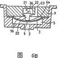
图9是按照本发明的第六实施例所构成的一个油墨盒的局部横截面视图,它示出了供墨腔室及其周围的结构;Figure 9 is a partial cross-sectional view of an ink cartridge constructed according to a sixth embodiment of the present invention, showing the structure of the ink supply chamber and its surroundings;
图10是按照本发明的第七实施例所构成的一个油墨盒的局部横截面视图,它示出了供墨腔室及其周围的结构;Figure 10 is a partial cross-sectional view of an ink cartridge constructed according to a seventh embodiment of the present invention, showing the structure of the ink supply chamber and its surroundings;
图11是表示按照本发明的第八个实施例所构成的一个油墨盒的供墨口的横截面视图;Figure 11 is a cross-sectional view showing an ink supply port of an ink cartridge constructed according to an eighth embodiment of the present invention;
图12A和图12B是表示按照本发明的第九个实施例所构成的一个油墨盒的供墨口的横截面视图,图12A表示的是未安装到记录头上的供墨口,图12B表示的是安装到记录头上的供墨口;12A and FIG. 12B are cross-sectional views showing an ink supply port of an ink cartridge constructed according to a ninth embodiment of the present invention. What FIG. is the ink supply port mounted on the recording head;
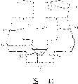
图13是表示供墨系统的示意图,该供墨系统是按照本发明的一个实施例的喷墨型记录设备的必要组成部分。Fig. 13 is a schematic diagram showing an ink supply system which is an essential component of an ink jet type recording apparatus according to an embodiment of the present invention.
具体实施方式Detailed ways
图13是表示本发明可应用的那种喷墨型记录设备中的供墨系统的示意图。Fig. 13 is a schematic diagram showing an ink supply system in an ink jet type recording apparatus to which the present invention is applicable.
喷墨型的打印头组件101通过一个连接件102而连接到油墨槽103上。油墨通过一个中空的针状体102a和连接件102上的供墨通道102b而从油墨槽103中供给到连接件102上的供墨通道102b而从油墨槽103中供给到打印头组件101中,这样该打印头组件101就根据打印信号而喷出油墨墨滴。The
图13所示的设备还包括一个处于非打印区域的盖件104,这个盖件104通过一个驱动机构(未示出)而抵靠在打印头组件101的喷嘴板上,以防止喷嘴口干燥。盖件104通过管108而与一个抽吸泵105相连接,所说的抽吸泵105由控制装置106操纵,以通过盖件104来抽吸打印头组件101中的油墨。图13中所示的设备上还设置有一个溢流槽107,它通过管109而与抽吸泵105的出口相连接。The device shown in FIG. 13 also includes a
记录头可以是任何结构的,例如欧洲专利申请Nos.581531、609863、584823等专利申请中所描述的那些结构。The recording head may be of any construction such as those described in European Patent Application Nos. 581531, 609863, 584823 and others.
参见图1,在本发明的第一实施例中,一个容器构成了油墨盒的盒体,盒体用标号1表示,这个盒体1上具有第一壁1a,第一壁1a上有一个供墨口2,记录头的供墨针状体(未示出)可插入到该供墨口2中。容器1的内部空间被薄膜阀座3分为一个油墨腔室4和一个供墨腔室5,这将在下文中予以描述。薄膜阀座3由弹性薄膜制成,例如橡胶薄膜、聚合合成橡胶薄膜或类似的材料,这种材料具有抗油墨性,在薄膜阀座3的中间形成有一个薄膜通孔6。薄膜阀座3被放置在一个在容器1的底部上形成的台阶7上。薄膜阀座3通过一个阀的组装件9而保持在拉伸状态,所说的阀组装件9顶靠着台阶7而将薄膜阀座3的周边夹持住。Referring to Fig. 1, in the first embodiment of the present invention, a container has constituted the box body of ink box, and box body is represented with numeral 1, has
阀体8可竖直移动地插入到一个穿过阀组装件9而形成的阀通孔10。阀体8所具有的一宽度保证了能让油墨流过阀组装件9与阀体8之间形成的间隙,阀体8的长度稍大于阀组装件9的厚度。在正常状态下,当墨盒1没有连接到进行打印操作的记录头上时,借助于一个阀体支承件11,阀体8的底部与薄膜阀座3弹性接触,以将薄膜阀座3上的薄膜通孔6封住。阀体8的底部设置成曲面形状,以与薄膜阀座3形成较好的密封。在阀组装件9的背向供墨口2的那个表面上有一个油墨通道15,该油墨通道15与阀通孔10相连通,用以将油墨引导到通孔10中。The
阀体支承件11安置在阀组装件9上,并且阀体支承件11的周边被固定在阀组装件9的表面上,阀体支承件11与薄膜阀座3分别位于阀组装件9的相对的两侧上,为了保持阀体8与薄膜阀座3弹性接触并防止阀体8降低到一预定的位置之下,阀体支承件11处于拉伸状态。阀体支承件11的制作材料与薄膜阀座3的材料相类似,在阀体支承件11上有一个通孔12,它构成了油墨通道15。还有,阀体支承件11在与通孔12相邻但又相距一定间隔的地方支承着阀体8的顶部8a。在这一实施例中,阀体8的上端有一个环形槽8b和一个头8a,所说的环形槽8b用于接纳阀支承件11上的安装孔11a的周边,由于头8a是个圆形的顶端,所以在安装时该头8a和环形槽8b是通过支承件11的弹性变形而穿过安装孔11a并使阀体保留在阀体的支承薄膜上。The
最好是在最终构成容器1之前将薄膜阀座3、阀体支承件11和阀体8组装并固定到阀组装件9上,并一次将整个组装件装入到容器1中的台阶7上。Preferably, the
容器1的上端由顶盖13封闭,顶盖13上有一个与大气连通的通孔14。在顶盖13的朝向油墨腔室4的内部的那一侧上,围绕着通气孔14形成有凹槽30、连通口32和窄槽31,所说的连通口32与凹槽30相距一段预定的距离,窄槽31构成了一个保持凹槽30与连通口32之间进行流体连通的毛细管通道。柔性件33以这样一种松驰的状态安置在凹槽30和窄槽31上,即,当将顶盖13放到容器1上时,该性件33与通气孔14之间保持一段很小的距离,与此同时,窄槽31所构成的毛细管通道的一个壁是由该柔性件33界定的。The upper end of the
在这一实施例中,如果容器1被置于这种状态——例如被倾斜或被倒置——而使得油墨腔室4中的油墨与顶盖13相接触,则柔性件33受到油墨的压力而向着顶盖13移动,于是该柔性件33与由通气孔14周围的凹槽30所界定出的凸台14a相接触,这样就将通气孔14封闭住,从而防止油墨从该通气孔14泄漏出去。In this embodiment, if the
当装载在滑架上的记录头(未示出)上的供墨针状体穿过供墨口2时(在正常状态下该供墨口被一个油墨不能渗透的密封件密封住,这个密封件未在图中示出,该密封件可被针状体以传统的方式刺穿),供墨腔室5通过这个供墨针状体而处于与记录头进行流体连通的状态。在这种情况下,顶盖13上的柔性件33由于重力或其它压力差而脱离顶盖13处于悬置状态,从而将通气孔14打开。这样,油墨腔室4就通过敞开的通气孔14、凹槽30、窄槽31以及连通口32而与大气连通。When the ink supply needle on the recording head (not shown) loaded on the carriage passes through the ink supply port 2 (in the normal state, the ink supply port is sealed by an ink impermeable seal, the seal Components not shown in the figure, the seal can be pierced by a needle in a conventional manner), the
正如图2A、2B和2C所示的那样,在以上述这种方式构成的墨盒中,当打印开始、记录头将油墨墨滴喷射到记录媒体或类似物上时,供墨腔室5中的油墨经过供墨口2流入到记录头中,供墨腔室5内部的压力因此而逐渐降低。相应于供墨腔室5内部的降低了的压力,薄膜阀座3受到来自油墨腔室4的压力而借助于其自身的弹性在朝向供墨口2的方向上伸展,伸展后的薄膜阀座3基本上呈一个半径为R的球面形状。此时,由于阀体8连同薄膜阀座3一起移动(见图2A),所以装在油墨腔室4中的油墨不能流入到供墨腔室5中,这就防止了供墨腔室5内部的压力过量增加,同时也防止了供墨腔室5内部的压力过量增加,同时也防止了供墨腔室5内部的压力过量地降低。以这种方式,就使得记录头上的压力相对于油墨腔室4总是保持在恒定的负压。As shown in FIGS. 2A, 2B and 2C, in the ink cartridge constituted in the above-mentioned manner, when printing starts and the recording head ejects ink droplets onto the recording medium or the like, the
当在打印操作期间记录头消耗了更多的油墨时,薄膜阀座3进一步朝着供墨口2进行弹性伸展。靠阀体支承件11来防止阀体8降低到一个预定的位置之下,这样就在阀体8与薄膜阀座3之间出现了一个很窄的间隙6a(见图2B)。在这种情况下,油墨腔室4中的油墨流经支承件上的通孔12、通道15、阀通孔10以及阀体8与薄膜阀座3之间的窄间隙6a而流过薄膜通孔6进入到供墨腔室5中。When more ink is consumed by the recording head during the printing operation, the
当油墨的内流引起了供墨腔室5内部的压力稍微增加时,薄膜阀座3靠其自身的弹性朝着阀体8向后移动并与阀体8弹性接触,由此而使得窄间隙6a和薄膜通孔6被阀体8的底面封闭住。这就使得油墨不能从油墨腔室4流入到供墨腔室5中。其结果是,供墨口上的压力保持在一个恒定的值上,而与油墨腔室4中的油墨量无关。When the inflow of ink causes the pressure inside the
因打印操作期间油墨的消耗而导致的供墨腔室5内部压力的每一次稍微降低都使得薄膜阀座3向着供墨口2稍微伸展,以在薄膜阀座3与阀体8之间形成间隙,通过这个间隙油墨从油墨腔室4流入到供墨腔室5中。按照这种方式,用弹性薄膜制成的薄膜阀座3根据打印期间油墨的消耗而与阀体8相接触或与阀体8相分离。这样,通过将薄膜阀座3的弹性的大小设定在一个合适的确定值上,就能够显著地减小在供墨开始和供墨结束之间的压力差,以及能够将油墨腔室4中的所有油墨排放到记录头中,从而使得油墨不会浪费。Every slight decrease in the pressure inside the
如果在打印未完成时周围环境的温度升高,则供墨腔室5内部的压力将增加。其它的环境因素的变化也会引起上述这种压力的增加。与这种增加的压力相应,薄膜阀座3向着油墨腔室4移动,该油墨腔室4是对着大气敞开的。这就防止了供墨腔室5内部的压力增加,这样就在油墨腔室4与记录头之间保持了适当的负压,而与上述的温度升高或压力增加无关。因此能够防止油墨因压力的增加而从记录头泄漏。If the temperature of the surrounding environment rises while printing is not completed, the pressure inside the
在一个最佳实施例中,薄膜阀座3是由一个厚度为0.04mm的橡胶薄膜构成的,它具有一个有效的直径,也即它的弹性变形范围为20mm。阀体8的最低极限位置是这样设计的,即,刚好在油墨流出之前——也即在薄膜阀座3处于与阀体8相分离的临界状态时,其球面半径R为26mm。现在参见图3,这是一幅曲线图,它表明了本发明的油墨盒中的流体压力值的变化。从图3中可以看出,即使提供大量的油墨,例如每分钟供给5克油墨,流体压力的增值也是很小的。这样,即使记录头消耗了大量的油墨,也可以平缓地向记录头提供油墨,而不会将超量的负压分配到记录头上。In a preferred embodiment, the
在填充油墨的过程中,对油墨腔室4施加负压以排出墨盒1中的空气。在供墨口2被一个密封件16封闭的情况下,油墨腔室4最初获得的压力低于供墨腔室5。这样,如图2C所示,阀体8克服阀体支承件11的弹力而向着油墨腔室4移动,从而在薄膜阀座3与阀体8之间形成一个填充油墨用的间隙12a,这样可将包括油墨腔室4和供墨腔室5在内的整个墨盒1中的所有空气排出,而与薄膜阀座3及阀体8是否存在无关。这就使得整个墨盒1——包括供墨腔室5都被填充上油墨。During ink filling, a negative pressure is applied to the
现在参见图4,该图给出了按照本发明的第二个实施例构成的油墨盒200,同样的构件用同样的标号标示。在这个第二实施例中,阀体8上有一个固定于其上的平的定位件35,该平定位件35面向阀体支承件11而固定在阀体8的一端上,它处于阀通孔10的区域内,当阀体8的底面与薄膜阀座3相接触时,该定位件35接近阀体8的上圆周面。当阀体8倚靠着薄膜阀座3时,定位件35与阀组装件9的上表面及阀体8的周边保持接触,阀体8由阀组装件9支承,以使阀体8的姿势尽可能地保持竖直。这样,即使墨盒20因滑架或类似构件的移动而受到振动,薄膜阀座3上的薄膜通孔6也能被阀体8可靠地封闭住。Referring now to Figure 4, which shows an
现在参见图5,该图绘出了按照本发明的第三个实施例构成的油墨盒300,同样的构件用同样的标号标示。在这个实施例中,阀组装件9′上有一个接纳阀体用的空腔9a,阀体20被插入到这个空腔9a中,安装在空腔9a中的弹簧21将阀体20推向供墨口2。阀体20的最低极限位置是由一个横向向外延伸的定位件36限定的,该定位件36形成于阀体20的上端,它倚靠着在接纳阀体用的空腔9a的底部上形成的横向向内延伸的凸台9b。还有,正如图5中所示的那样,借助于通孔22和23,可有选择地使油墨腔室4与供墨腔室5保持流体连通,通孔22使得油墨腔室4与接纳阀体用的空腔9a直接连通,通孔23连通油墨腔室4与薄膜阀座3之间的空间并具有一个横向延伸的面槽23a,该面槽23a形成于阀组装件9′上的那个面对着所说的薄膜阀座3的侧面上,并延伸于通孔23与空腔9a之间。Referring now to Figure 5, which depicts an
在这第三个实施例中,正如图6A、6B和6C所示的那样,随着供墨腔室5内部压力的降低,薄膜阀座3受到来自油墨腔室4的压力,它借助于自身的弹性向着供墨口2伸展,它基本呈一个半径为R的球面形状。这样,由于阀体20靠弹簧21的弹力而与薄膜阀座3一起移动,并且定位件36倚靠在凸台9b上来使阀体20保持竖直的姿势(见图6A),所以当防止供墨腔室5中的压力过量下降时油墨不会从油墨腔室4中流入到供墨腔室5中。以这种方式,薄膜阀座3贴靠着阀体20,不会受到由于滑架的运动而导致的任何振动或摆动的影响,从而使得记录头上的油墨压力相对于油墨腔室4保持在恒定的负压。In this third embodiment, as shown in FIGS. 6A, 6B and 6C, as the internal pressure of the
当在打印操作过程中打印头消耗了更多的油墨时,薄膜阀座3进一步向着供墨口2伸展。借助于接纳阀体用的空腔9a中的凸台9b,防止了阀体20下降到一个预定的位置之下,这样阀体8就与薄膜阀座3分开了一段很窄的间隔6a(见图6B)。在这种情况下,油墨腔室4中的油墨经过在阀体20与薄膜阀座3之间形成的窄间隙6a而流过薄膜通孔6进入到供墨腔室5中。When the print head consumes more ink during the printing operation, the
当油墨的内流引起了供墨腔室5的内部压力稍微增加时,薄膜阀座3靠其自身的弹性而向着阀体20回移并与阀体20弹性接触,由此就使得窄间隙6a和薄膜通孔6被阀体20的底面封闭住。这就防止了油墨从油墨腔室4流入到供墨腔室5中。其结果是,供墨口2上的压力被保持在一个恒定值上,而与盛装在油墨腔室4中的油墨量无关。When the inflow of ink causes the internal pressure of the
在制造及填充油墨的过程中,对油墨腔室4提供负压,以排出墨盒300中的空气。在供墨口2被密封件16封住的情况下,油墨腔室4中的压力低于供墨腔室5中的压力。这样,如图6C所示,阀体20克服弹簧21的弹力而向着油墨腔室4移动,从而在薄膜阀座3与阀体20之间形成了一个填充油墨用的间隙12a,这样可将整个墨盒300中的所有空气排出,而与薄膜阀座3及阀体20的存在无关。这就使得包括供墨腔室5在内的整个墨盒300被充满油墨。During the process of manufacturing and filling ink, a negative pressure is provided to the
在上述这个第三实施例中,在阀组装件9′中装有一个用于使阀体20与薄膜阀座3相接触的弹性件(弹簧21)。在一个替换的第四实施例中,同样的构件用同样的标号标示,如图7所示,油墨盒400中可装有阀体37,它呈一种蘑菇形状,其头部37a起到一种定位件和止挡块的作用;弹簧38的周边安装在阀组装件9″的顶面上,这个弹簧38可用来向着薄膜阀座3的方向推阀体37的顶部。由于可从阀组装件9″的外部安装阀体37和弹簧38,所以该油墨盒的装配工作可得以简化。阀组装件9″上的通孔9c把油墨腔室4与在阀组装件9″的底面和薄膜阀座3之间形成的空间连通起来。In the third embodiment described above, an elastic member (spring 21) for making the
现在参见图8,它绘出了按照本发明的第五实施例构成的油墨盒500,同样的构件用同样的标号标示。在上述的几个实施例中,弹簧是安置在阀体的上方的,很显然,当用一块其上具有通孔41a的隔板41将油墨盒500分隔成油墨腔室42和供墨腔室43时,可以产生同样的效果。供墨腔室43中装有薄膜阀座44和阀体46,阀体46包括一个细长部分46b和一个头部,其细长部分46b穿过薄膜通孔45,其头部具有一个呈球形的底面46a,用以密封薄膜阀座44上的薄膜通孔45。细长部分46b从底面46a延伸出来并垂直于该底面46面细长部分46b穿过薄膜阀座44上的薄膜通孔45。细长部分46b穿过弹簧47并被支承在弹簧47上,该弹簧47总是在供墨口49和导孔48的方向上推着细长部分46b并因此而推着阀体46,如图8所示,所说的导孔48接纳细长部分46b的底端而使得阀体46以竖直的姿势定位于墨盒的一个壁上。导孔48是由油墨盒500的底壁49a上所形成的一个向上伸出的环形壁43a围成的。Referring now to Figure 8, which depicts an
按照这个第五实施例,由于阀体46总是被弹簧47推向壁49a(在壁49a上有供墨口49),以保持稳定的状态,而与油墨所产生的任何力无关,所以可稳定地向记录头提供油墨,而不会受到因滑架的运动而导致的墨盒500的任何振动或摇动的影响。在这一实施例中,与上文所述的那些相类似,当由于打印操作期间油墨被消耗而使得薄膜阀座44下方的压力降低时,薄膜阀座44朝着供墨口49移动,由此而保持住阀座44下方的压力。当细长部分46b接触到导孔48的底部时,阀体46停止移动。之后,任何附加的油墨消耗都使得薄膜阀座44移动而离开阀体46的上部底面46a,由此而露出薄膜通孔45,使得油墨能从该孔45处流过。According to this fifth embodiment, since the
现在参见图9,该图给出了按照本发明的第六个实施例而构成的油墨盒600,同样的构件用同样的标号标示。一种由软的多孔薄膜或网格薄膜制成的水平稳定的薄膜50可与薄膜阀座3一起移动。多孔件上的通孔51是穿过稳定的薄膜50上的与阀体8相对着的那一区域而形成的,阀体8的底端装配在多孔件的通孔51中。稳定的薄膜50的周边固定在阀组装件9上,其中心部分固定在阀体8上。Referring now to Fig. 9, which shows an
当随着打印期间更多的油墨被消耗,供墨腔室5内部的压力降低时,薄膜阀座3与阀体8分开,这样油墨腔室4中的油墨就流过水平稳定的薄膜50上的多孔件上的通孔51而进入到供墨腔室5中。When the pressure inside the
当在打印操作期间消耗了附加量的油墨并且油墨腔室4中的油墨的液面已降至到低于阀组装件9的位置之后,油墨腔室4中的油墨会因滑架的运动而在阀体8附近剧烈地晃动。但由于油墨是在油墨的压力波动已被水平稳定的薄膜50尽可能地抑制了之后流过薄膜阀座3上的薄膜通孔6的,所以记录头上的油墨压力保持在一个恒定值上,而与油墨腔室4中剩留的油墨量无关。After an additional amount of ink is consumed during the printing operation and the ink level in the
在上文所述的几个实施例中,用一个弹性件(阀体支承件11)来使得阀体8与薄膜阀座3之间保持弹性接触,如果薄膜阀座3的弹力被有效地利用的话,则这个用于使阀体8与薄膜阀座3进行弹性接触的弹性件就不是必需的。In several embodiments described above, an elastic member (valve body supporting member 11) is used to maintain elastic contact between the
现在参见图10,该图给出了按照本发明的第七个实施例而构成的油墨盒700,同样的构件用同样的标号标示。这个第七实施例不需要一个用以弹性地推着阀体而使其与薄膜座保持接触的弹性件。Referring now to Fig. 10, which shows an
正如图10所示的那样,薄膜阀座24上有一个薄膜通孔25,该通孔25处于与阀体28相对置的区域上(这将在下文中描述),薄膜阀座24的周边由阀组装件27固定。阀体28不可移动地固定在阀组装件27上并处于一个与阀组装件27相垂直的位置上。借助于一个从阀体28延伸的呈径向伸长槽形状的连通孔29,油墨腔室4有选择地与供墨腔室5保持流体连通。当油墨腔室4与供墨腔室5之间的压力差等于或小于一预定值时,薄膜阀座24通过其自身的弹性而将薄膜通孔25带至与阀体28相接触,从而使油墨腔室4中的油墨停止流向供墨腔室5。As shown in Figure 10, a film through
另一方面,如果供墨腔室5内部的压力降低,则薄膜阀座24呈球面形向着供墨口2延伸,薄膜通孔25因此而脱离与阀体28的接触,因此而使得油墨从油墨腔室4经过薄膜通孔25流入到供墨腔室5中。在向供墨腔室5提供了足够量的油墨以提高供墨腔室5内部的压力之后,薄膜阀座24克服油墨腔室4与供墨腔室5之间的压力差而与阀体28弹性接触,从而使油墨腔室4中的油墨停止流向供墨腔室5。On the other hand, if the pressure inside the
现在参见图11,该图绘出了按照本发明的第八个实施例而构成的油墨盒,同样的构件用同样的标号标示。这一实施例中的油墨盒能在记录头用尽了油墨盒中的所有油墨的时候防止空气进入记录头。在供墨口52与供墨腔室53之间的连通区域上设置了一个向下斜锥的圆锥阀座54。在这个圆锥阀座54中装有一个球形的浮子阀55,由这个球形的浮子阀55的浮性而产生的浮力使得该球形浮子阀55漂浮。进一步说,在圆锥阀座54的上端盖有一块阀挡板56,它是由可漏过油墨的材料(例如丝网)制成的,以构成一个遮护阀。在图11中,薄膜阀座57也是有选择地与阀体58相接触,以控制油墨腔室(未示出)中的油墨的流动。Referring now to Fig. 11, which shows an ink cartridge according to an eighth embodiment of the present invention, like components are designated by like reference numerals. The ink cartridge in this embodiment prevents air from entering the recording head when the recording head has used up all the ink in the ink cartridge. On the communication area between the
当将油墨盒安装到记录头上时,浮子阀55向上浮起并靠浮力而顶靠在阀挡板56上,以打开供墨口52,油墨通过这个供墨口52供给到记录头中。当在打印期间墨盒中的油墨被消耗时,墨盒中油墨的液面下降到供墨口52附近。因为没有了油墨,所以浮子阀55失去其浮力而因此与阀座54相接触,以关闭供墨口52(如图11中虚线所示)。即使在墨盒几乎被排空的情况下继续进行打印,已关闭的供墨口52也能阻止空气进入记录头,这样防止了不合格的打印。When the ink cartridge is mounted on the recording head, the
通常,一旦将墨盒安装到记录头上,该墨盒就不再被移走,直到盛装在油墨腔室中的油墨用完为止。然而,有时也会由于操作错误而使得墨盒被从记录头上卸下。如果一个曾经被安装过的墨盒被从记录头上卸下,则供墨口52是对着大气敞开的,于是就使得空气进入到供墨腔室和油墨腔室中,这会对打印期间油墨的流动产生不利的影响。Usually, once the ink cartridge is mounted on the recording head, the ink cartridge is not removed until the ink contained in the ink chamber is used up. However, sometimes the ink cartridge is removed from the recording head due to an operation error. If an ink cartridge once installed is removed from the recording head, the
现在参见图12A和图12B,这两幅图绘出了按照本发明的第九个实施例构成的油墨盒,同样的构件用同样的标号标示。如图12A和图12B所示,如果在油墨用完之前该墨盒被卸下的话,这个第九实施例中的墨盒能够防止空气进入墨盒。在供墨口61上安置一个可伸缩的阀体60,在阀体60的底部有一个供墨针状体的安装孔62,供墨针状体70可拆卸地装配到这个安装孔62中。阀体60上还有一个连通孔64,它用于当阀体60向上移至上方的极限位置上时将供墨腔室63与供墨针状体的安装孔62连通起来。Referring now to Figures 12A and 12B, these two figures depict an ink cartridge constructed according to a ninth embodiment of the present invention, and like components are designated by like reference numerals. As shown in FIGS. 12A and 12B, the ink cartridge in this ninth embodiment can prevent air from entering the ink cartridge if the ink cartridge is removed before the ink is used up. A
在这个实施例中,在插入供墨针状体70之前,如图12A所示,阀体60(该阀体60有一个径向延伸的弹性周边60a)靠其自身的弹性与供墨腔室63的底面63a保持弹性接触,以防止供墨腔室63中的油墨外流。In this embodiment, before inserting the
当供墨针状体70插入到装配孔62中时,阀体60与供墨腔室63的底面63a相脱离并向上延伸到极限位置,此时连通孔64是露出在供墨腔室63中的(见图12B)。这就使得供墨腔室63通过连通孔64和针状体的连通孔70b而与供墨针状体70的油墨通道70a进行流体连通,由此而使得供墨腔室63中的油墨流入供墨针状体70并随后提供给记录头。When the
当将安装在记录头上的墨盒卸下时,阀体60向着图12A的底部移动,以关闭供墨口61,并因此而封闭供墨腔室63。这就防止了供墨腔室63中的油墨外流,同时防止空气进入到供墨腔室63中。When the ink cartridge mounted on the recording head is removed, the
如上所述,按照本发明,在其一个壁上具有供墨口的墨盒被一个由弹性薄膜制成的薄膜阀座分隔开,该薄膜阀座的中心部位具有通孔。该墨盒中油墨腔室处于不与供墨口相邻的区域,供墨腔室处于与供墨口邻接的区域中,阀体被放置在与所说的通孔相对的位置上。由于油墨的消耗,薄膜阀座在很大的面积上受到压力差的作用,并且相应于一次少量的油墨消耗而允许油墨从油墨腔室中流出。这样,可在不会在记录头上产生超量的负压的情况下向记录头提供油墨,并且可以毫无浪费地将油墨腔室中的油墨排放到记录头中。此外,如果在打印尚未完成时周围环境温度大幅度升高或因其它环境因素而引起压力增加,则薄膜阀座向着油墨腔室位移,以释放由于供墨腔室内部的压力升高而增加了的压力,所说的供墨腔室将记录头与油墨腔室连通起来。因此就能够在该打印机未被使用时防止油墨泄漏。还有,当该墨盒安装到记录头上时,在记录头与墨盒之间保持了适合于打印的负压,从而确保了稳定的打印。As described above, according to the present invention, the ink cartridge having the ink supply port on one wall thereof is partitioned by a membrane valve seat made of an elastic membrane having a through hole at the center thereof. In the ink box, the ink chamber is located in a region not adjacent to the ink supply port, the ink supply chamber is located in a region adjacent to the ink supply port, and the valve body is placed at a position opposite to the through hole. Due to the consumption of ink, the diaphragm valve seat is exposed to a pressure difference over a large area and allows the ink to flow out of the ink chamber corresponding to a small ink consumption. In this way, the ink can be supplied to the recording head without generating an excessive negative pressure on the recording head, and the ink in the ink chamber can be discharged into the recording head without waste. In addition, if the ambient temperature rises greatly or the pressure increases due to other environmental factors when printing is not completed, the diaphragm valve seat is displaced toward the ink chamber to release the increased pressure due to the increase in the pressure inside the ink supply chamber. The pressure of the ink supply chamber communicates the recording head with the ink chamber. Therefore, ink leakage can be prevented when the printer is not in use. Also, when the ink cartridge is mounted on the recording head, a negative pressure suitable for printing is maintained between the recording head and the ink cartridge, thereby ensuring stable printing.
进一步说,由于薄膜阀座所具有的弹性能够保证在薄膜阀座工件之间实现紧密的密封,所以这个阀能够可靠地实现阀的功能,而不会受到因滑架的运动而导致的油墨腔室中油墨的任何振动或晃动的影响,这样就能够在该墨盒与记录头之间保持压力差,而不会受到滑架运动的影响,从而提高打印质量。Furthermore, since the elasticity of the diaphragm valve seat can ensure a tight seal between the diaphragm valve seat workpieces, this valve can reliably perform the function of the valve without being affected by the ink cavity caused by the movement of the carriage. Any vibration or shaking of the ink in the chamber, so that a pressure differential can be maintained between the ink cartridge and the recording head without being affected by the movement of the carriage, thereby improving print quality.
因此人们将看出,上文中所述的发明目的以及那些从上文的叙述中很显见的效果都已得以充分的实现,由于可在不脱离本发明的精神和范围的情况下在上述这些结构上进行一定的变化,所以包含在上述的文字叙述及所示的附图中的所有内容都应当被理解为是在举例说明,而不是对本发明的限制。Therefore it will be seen that the purpose of the invention described above and those obvious effects from the above description have been fully realized, because these structures can be used without departing from the spirit and scope of the present invention. Therefore, all the contents contained in the above written description and the accompanying drawings should be interpreted as illustrative rather than limiting of the present invention.
还应当理解的是,随后的权利要求将覆盖这里所描述的本发明的所有的一般及特殊的特征,对本发明的范围的所有说明都落在该权利要求当中。It is also to be understood that the following claims are to cover all generic and specific features of the invention described herein, and that all indications of the scope of the invention fall within such claims.
Claims (19)
Applications Claiming Priority (3)
| Application Number | Priority Date | Filing Date | Title |
|---|---|---|---|
| JP28729294 | 1994-10-26 | ||
| JP1994287292 | 1994-10-26 | ||
| JP1995258101 | 1995-09-11 |
Related Parent Applications (1)
| Application Number | Title | Priority Date | Filing Date |
|---|---|---|---|
| CNB021482594ADivisionCN1299910C (en) | 1994-10-26 | 2002-10-28 | Ink cartridge for inkjet recording device and inkjet recording device |
Publications (1)
| Publication Number | Publication Date |
|---|---|
| CN101028763Atrue CN101028763A (en) | 2007-09-05 |
Family
ID=37596771
Family Applications (3)
| Application Number | Title | Priority Date | Filing Date |
|---|---|---|---|
| CNA2006100911306APendingCN1891469A (en) | 1994-10-26 | 1995-10-26 | Ink cartridge for ink-jet recording equipment and ink-jet recording equipment |
| CN 200610091132PendingCN101028763A (en) | 1994-10-26 | 1995-10-26 | Ink cartridge for ink-jet recorder and ink-jet recorder |
| CN2006100911310AExpired - LifetimeCN1891470B (en) | 1994-10-26 | 1995-10-26 | Ink cartridge for ink-jet recording equipment and ink-jet recording equipment |
Family Applications Before (1)
| Application Number | Title | Priority Date | Filing Date |
|---|---|---|---|
| CNA2006100911306APendingCN1891469A (en) | 1994-10-26 | 1995-10-26 | Ink cartridge for ink-jet recording equipment and ink-jet recording equipment |
Family Applications After (1)
| Application Number | Title | Priority Date | Filing Date |
|---|---|---|---|
| CN2006100911310AExpired - LifetimeCN1891470B (en) | 1994-10-26 | 1995-10-26 | Ink cartridge for ink-jet recording equipment and ink-jet recording equipment |
Country Status (1)
| Country | Link |
|---|---|
| CN (3) | CN1891469A (en) |
Cited By (2)
| Publication number | Priority date | Publication date | Assignee | Title |
|---|---|---|---|---|
| CN104057712A (en)* | 2013-03-22 | 2014-09-24 | 兄弟工业株式会社 | Print Fluid Cartridge Having Print Fluid Supply Portion, And Print Fluid Supplying Apparatus |
| CN113015627A (en)* | 2018-11-20 | 2021-06-22 | 惠普发展公司,有限责任合伙企业 | Printer fluid port |
Families Citing this family (2)
| Publication number | Priority date | Publication date | Assignee | Title |
|---|---|---|---|---|
| CN110877482B (en)* | 2019-12-06 | 2021-07-27 | 浙江聚众柔印科技有限公司 | Ink Supply Mechanism in Flexo Printing Unit |
| CN114393927A (en)* | 2022-01-25 | 2022-04-26 | 珠海富力特电子有限公司 | Ink jet printing apparatus and valve assembly therefor |
Family Cites Families (5)
| Publication number | Priority date | Publication date | Assignee | Title |
|---|---|---|---|---|
| US3270771A (en)* | 1963-06-11 | 1966-09-06 | Robertshaw Controls Co | Resilient disc check valve |
| DE3202796C2 (en)* | 1982-01-28 | 1984-02-23 | Adam Opel AG, 6090 Rüsselsheim | Check valve, in particular a delay valve for a closing movement of the carburetor throttle valve of internal combustion engines controlled by the intake manifold vacuum |
| US4677447A (en)* | 1986-03-20 | 1987-06-30 | Hewlett-Packard Company | Ink jet printhead having a preloaded check valve |
| US5343226A (en)* | 1990-09-28 | 1994-08-30 | Dataproducts Corporation | Ink jet ink supply apparatus |
| JPH04214360A (en)* | 1990-12-10 | 1992-08-05 | Canon Inc | Ink jet recording device, ink tank cartridge for said device and manufacture of said cartridge |
- 1995
- 1995-10-26CNCNA2006100911306Apatent/CN1891469A/enactivePending
- 1995-10-26CNCN 200610091132patent/CN101028763A/enactivePending
- 1995-10-26CNCN2006100911310Apatent/CN1891470B/ennot_activeExpired - Lifetime
Cited By (5)
| Publication number | Priority date | Publication date | Assignee | Title |
|---|---|---|---|---|
| CN104057712A (en)* | 2013-03-22 | 2014-09-24 | 兄弟工业株式会社 | Print Fluid Cartridge Having Print Fluid Supply Portion, And Print Fluid Supplying Apparatus |
| US9126415B2 (en) | 2013-03-22 | 2015-09-08 | Brother Kogyo Kabushiki Kaisha | Print fluid cartridge having print fluid supply portion, and print fluid supplying apparatus |
| CN104057712B (en)* | 2013-03-22 | 2016-04-20 | 兄弟工业株式会社 | There is printing-fluid box and the printing-fluid supply equipment of printing-fluid supply section |
| CN113015627A (en)* | 2018-11-20 | 2021-06-22 | 惠普发展公司,有限责任合伙企业 | Printer fluid port |
| US11390088B2 (en) | 2018-11-20 | 2022-07-19 | Hewlett-Packard Development Company, L.P. | Printer fluid ports |
Also Published As
| Publication number | Publication date |
|---|---|
| CN1891469A (en) | 2007-01-10 |
| CN1891470B (en) | 2011-03-02 |
| CN1891470A (en) | 2007-01-10 |
Similar Documents
| Publication | Publication Date | Title |
|---|---|---|
| CN1299910C (en) | Ink cartridge for inkjet recording device and inkjet recording device | |
| CN101028763A (en) | Ink cartridge for ink-jet recorder and ink-jet recorder | |
| HK1101966A (en) | An ink cartridge for an ink jet recording apparatus and an ink jet recording apparatus | |
| HK1113915A (en) | An ink cartridge for ink-jet recording apparatus and an ink-jet recording apparatus | |
| HK1101965B (en) | An ink cartridge for an ink jet recording apparatus and an ink jet recording apparatus | |
| JP4006606B2 (en) | ink cartridge | |
| JP2007050711A (en) | Ink cartridge | |
| JP2007015404A (en) | Ink cartridge manufacturing method | |
| JP2007015402A (en) | Ink cartridge manufacturing method | |
| JP2007015405A (en) | Ink cartridge manufacturing method | |
| JP2004001564A (en) | ink cartridge | |
| HK1053627B (en) | Ink cartridge for ink jet printer | |
| JP2007015401A (en) | ink cartridge | |
| HK1053810B (en) | Ink cartridge for ink jet printer | |
| JP2003025606A (en) | ink cartridge |
Legal Events
| Date | Code | Title | Description |
|---|---|---|---|
| C06 | Publication | ||
| PB01 | Publication | ||
| C10 | Entry into substantive examination | ||
| SE01 | Entry into force of request for substantive examination | ||
| REG | Reference to a national code | Ref country code:HK Ref legal event code:DE Ref document number:1113915 Country of ref document:HK | |
| C12 | Rejection of a patent application after its publication | ||
| RJ01 | Rejection of invention patent application after publication | Open date:20070905 | |
| REG | Reference to a national code | Ref country code:HK Ref legal event code:WD Ref document number:1113915 Country of ref document:HK |