CN101028194A - X-ray diagnostic apparatus - Google Patents
X-ray diagnostic apparatusDownload PDFInfo
- Publication number
- CN101028194A CN101028194ACNA2006100916812ACN200610091681ACN101028194ACN 101028194 ACN101028194 ACN 101028194ACN A2006100916812 ACNA2006100916812 ACN A2006100916812ACN 200610091681 ACN200610091681 ACN 200610091681ACN 101028194 ACN101028194 ACN 101028194A
- Authority
- CN
- China
- Prior art keywords
- image
- vessel
- ray
- blood
- unit
- Prior art date
- Legal status (The legal status is an assumption and is not a legal conclusion. Google has not performed a legal analysis and makes no representation as to the accuracy of the status listed.)
- Granted
Links
Images


Classifications
- A—HUMAN NECESSITIES
- A61—MEDICAL OR VETERINARY SCIENCE; HYGIENE
- A61B—DIAGNOSIS; SURGERY; IDENTIFICATION
- A61B6/00—Apparatus or devices for radiation diagnosis; Apparatus or devices for radiation diagnosis combined with radiation therapy equipment
- A61B6/50—Apparatus or devices for radiation diagnosis; Apparatus or devices for radiation diagnosis combined with radiation therapy equipment specially adapted for specific body parts; specially adapted for specific clinical applications
- A61B6/504—Apparatus or devices for radiation diagnosis; Apparatus or devices for radiation diagnosis combined with radiation therapy equipment specially adapted for specific body parts; specially adapted for specific clinical applications for diagnosis of blood vessels, e.g. by angiography
- A—HUMAN NECESSITIES
- A61—MEDICAL OR VETERINARY SCIENCE; HYGIENE
- A61B—DIAGNOSIS; SURGERY; IDENTIFICATION
- A61B6/00—Apparatus or devices for radiation diagnosis; Apparatus or devices for radiation diagnosis combined with radiation therapy equipment
- A61B6/42—Arrangements for detecting radiation specially adapted for radiation diagnosis
- A61B6/4208—Arrangements for detecting radiation specially adapted for radiation diagnosis characterised by using a particular type of detector
- A61B6/4233—Arrangements for detecting radiation specially adapted for radiation diagnosis characterised by using a particular type of detector using matrix detectors
- A—HUMAN NECESSITIES
- A61—MEDICAL OR VETERINARY SCIENCE; HYGIENE
- A61B—DIAGNOSIS; SURGERY; IDENTIFICATION
- A61B6/00—Apparatus or devices for radiation diagnosis; Apparatus or devices for radiation diagnosis combined with radiation therapy equipment
- A61B6/44—Constructional features of apparatus for radiation diagnosis
- A61B6/4429—Constructional features of apparatus for radiation diagnosis related to the mounting of source units and detector units
- A61B6/4435—Constructional features of apparatus for radiation diagnosis related to the mounting of source units and detector units the source unit and the detector unit being coupled by a rigid structure
- A61B6/4441—Constructional features of apparatus for radiation diagnosis related to the mounting of source units and detector units the source unit and the detector unit being coupled by a rigid structure the rigid structure being a C-arm or U-arm
- A—HUMAN NECESSITIES
- A61—MEDICAL OR VETERINARY SCIENCE; HYGIENE
- A61B—DIAGNOSIS; SURGERY; IDENTIFICATION
- A61B6/00—Apparatus or devices for radiation diagnosis; Apparatus or devices for radiation diagnosis combined with radiation therapy equipment
- A61B6/46—Arrangements for interfacing with the operator or the patient
- A61B6/461—Displaying means of special interest
- A61B6/466—Displaying means of special interest adapted to display 3D data
- A—HUMAN NECESSITIES
- A61—MEDICAL OR VETERINARY SCIENCE; HYGIENE
- A61B—DIAGNOSIS; SURGERY; IDENTIFICATION
- A61B6/00—Apparatus or devices for radiation diagnosis; Apparatus or devices for radiation diagnosis combined with radiation therapy equipment
- A61B6/48—Diagnostic techniques
- A61B6/481—Diagnostic techniques involving the use of contrast agents
- G—PHYSICS
- G06—COMPUTING OR CALCULATING; COUNTING
- G06T—IMAGE DATA PROCESSING OR GENERATION, IN GENERAL
- G06T7/00—Image analysis
- G06T7/30—Determination of transform parameters for the alignment of images, i.e. image registration
- G06T7/32—Determination of transform parameters for the alignment of images, i.e. image registration using correlation-based methods
- A—HUMAN NECESSITIES
- A61—MEDICAL OR VETERINARY SCIENCE; HYGIENE
- A61B—DIAGNOSIS; SURGERY; IDENTIFICATION
- A61B6/00—Apparatus or devices for radiation diagnosis; Apparatus or devices for radiation diagnosis combined with radiation therapy equipment
- A61B6/44—Constructional features of apparatus for radiation diagnosis
- A61B6/4429—Constructional features of apparatus for radiation diagnosis related to the mounting of source units and detector units
- A61B6/4464—Constructional features of apparatus for radiation diagnosis related to the mounting of source units and detector units the source unit or the detector unit being mounted to ceiling
- G—PHYSICS
- G06—COMPUTING OR CALCULATING; COUNTING
- G06T—IMAGE DATA PROCESSING OR GENERATION, IN GENERAL
- G06T2207/00—Indexing scheme for image analysis or image enhancement
- G06T2207/10—Image acquisition modality
- G06T2207/10072—Tomographic images
- G06T2207/10081—Computed x-ray tomography [CT]
- G—PHYSICS
- G06—COMPUTING OR CALCULATING; COUNTING
- G06T—IMAGE DATA PROCESSING OR GENERATION, IN GENERAL
- G06T2207/00—Indexing scheme for image analysis or image enhancement
- G06T2207/30—Subject of image; Context of image processing
- G06T2207/30004—Biomedical image processing
- G06T2207/30101—Blood vessel; Artery; Vein; Vascular
Landscapes
- Health & Medical Sciences (AREA)
- Life Sciences & Earth Sciences (AREA)
- Engineering & Computer Science (AREA)
- Medical Informatics (AREA)
- Physics & Mathematics (AREA)
- Radiology & Medical Imaging (AREA)
- Heart & Thoracic Surgery (AREA)
- Veterinary Medicine (AREA)
- Biophysics (AREA)
- High Energy & Nuclear Physics (AREA)
- Public Health (AREA)
- Nuclear Medicine, Radiotherapy & Molecular Imaging (AREA)
- Optics & Photonics (AREA)
- Pathology (AREA)
- General Health & Medical Sciences (AREA)
- Biomedical Technology (AREA)
- Animal Behavior & Ethology (AREA)
- Molecular Biology (AREA)
- Surgery (AREA)
- Human Computer Interaction (AREA)
- Computer Vision & Pattern Recognition (AREA)
- General Physics & Mathematics (AREA)
- Theoretical Computer Science (AREA)
- Mathematical Physics (AREA)
- Vascular Medicine (AREA)
- Dentistry (AREA)
- Oral & Maxillofacial Surgery (AREA)
- Apparatus For Radiation Diagnosis (AREA)
Abstract
Translated fromChineseDescription
Translated fromChinese技术领域technical field
本发明涉及生成血管结构的路径图的X射线诊断装置。The present invention relates to an X-ray diagnostic apparatus for generating a road map of a blood vessel structure.
背景技术Background technique
在干预或血管造影检查中,将导管从例如腿的关节插入到血管中,并通过血管引导到目标区域。在X射线透视观察下,将该导管或插入到导管中的导丝推向目标位置。但是,除非用造影剂增强,否则在X射线图像中看不见血管。持续注入造影剂以显现血管可能导致肾衰竭。由于这个原因,提供路径图功能,它显示造影剂一旦注入之后检测出的图像和叠加它们时的X射线透射图像。该功能允许操作员不注入任何造影剂在一定程度上辨别血管的位置,因此尤其当血管结构复杂和难以将导管或导丝推入血管中时经常使用。但是,根据该路径图功能,床的移动、为改变观察方向而进行的臂的转动、病人的轻微运动(激动)等的发生使重新生成路径图图像是必要的。频繁地重新生成路径图图像导致检查时间和使用的造影剂量的增加。During an intervention or angiographic examination, a catheter is inserted into a blood vessel from, for example, a joint in the leg and guided through the blood vessel to the target area. Under X-ray fluoroscopy, the catheter or a guide wire inserted into the catheter is pushed toward the target location. However, blood vessels are not visible in X-ray images unless they are enhanced with a contrast agent. Continuous injection of contrast material to visualize blood vessels may lead to kidney failure. For this reason, a roadmap function is provided, which displays images detected once the contrast agent is injected and X-ray transmission images when superimposing them. This function allows the operator to discern the position of the vessel to some extent without injecting any contrast agent, so it is often used especially when the vessel structure is complex and it is difficult to push the catheter or guide wire into the vessel. However, according to the road map function, it is necessary to regenerate the road map image due to the movement of the bed, the rotation of the arm to change the observation direction, the slight movement (excitement) of the patient, and the like. Frequent regeneration of the roadmap image leads to an increase in examination time and contrast volume used.
为了解决这种问题,在减少使用的造影剂量和缩短检查时间方面,其中使用3D图像生成的路径图图像和透视图像彼此叠加的3D路径图被预期是有效的。In order to solve such problems, a 3D road map in which a road map image generated using a 3D image and a fluoroscopic image are superimposed on each other is expected to be effective in reducing the amount of contrast used and shortening examination time.
为了机械地叠加3D图像和X射线图像,可以使用生成位移表的方法。但是,因为对医疗所使用的角度没有施加特别限制,需要大量校准数据。该方法不能跟随医疗期间病人的运动。In order to mechanically superimpose the 3D image and the X-ray image, a method of generating a displacement table can be used. However, since no particular limitation is imposed on angles used in medical treatment, a large amount of calibration data is required. This method cannot follow the movement of the patient during medical treatment.
在学术会议等中,已提出了一种假定导管经过血管通过从透视图像中提取导管执行校准的方法。但是,在具有复杂血管结构的区域中,有误定血管之间对应性的风险。另外,血管形状可能被导管改变。此外,如果病人移动,通过使用上面的方法很难做出修正。In an academic conference or the like, a method of performing calibration by extracting a catheter from a fluoroscopic image assuming that the catheter passes through a blood vessel has been proposed. However, in regions with complex vessel structures, there is a risk of misascertaining the correspondence between vessels. Additionally, vessel shape may be altered by the catheter. Furthermore, if the patient moves, it is difficult to make corrections by using the above method.
发明内容Contents of the invention
本发明的一个目的在于,通过定位非血管图像和X射线图像而不机械地叠加它们,从而不必生成位移表就能应对病人的运动。本发明的另一个目的在于通过当定位之后叠加时显示透视图像和非血管图像,向操作员显示3D图像和透视图像之间的位移。It is an object of the present invention to account for patient motion without having to generate displacement tables by positioning non-vascular and x-ray images without mechanically superimposing them. Another object of the present invention is to show the displacement between the 3D image and the fluoroscopic image to the operator by displaying the fluoroscopic image and the non-vascular image when superimposed after positioning.
根据本发明的第一方面,提供了一种X射线诊断装置,其包括具有X射线管和X射线探测单元以生成X射线图像的X射线成像单元,从X射线诊断装置或X射线CT装置所生成的原始3D图像中生成3D非血管图像和3D血管图像的图像生成单元,从3D非血管图像中生成非血管投影图像和从3D血管图像中生成血管投影图像的投影图像生成单元,识别X射线图像和非血管投影图像之间位移的位移识别单元,基于位移校正血管投影图像的位移的校正单元,以及显示X射线图像和校正后的血管投影图像的显示单元。According to a first aspect of the present invention, there is provided an X-ray diagnostic apparatus including an X-ray imaging unit having an X-ray tube and an X-ray detection unit to generate an X-ray image, from the X-ray diagnostic apparatus or the X-ray CT apparatus An image generation unit that generates a 3D non-vascular image and a 3D blood vessel image from the generated original 3D image, a projection image generation unit that generates a non-vascular projection image from the 3D non-vascular image and a projection image generation unit that generates a blood vessel projection image from the 3D blood vessel image, and recognizes X-rays A displacement recognition unit for displacement between the image and the non-vascular projection image, a correction unit for correcting the displacement of the vascular projection image based on the displacement, and a display unit for displaying the X-ray image and the corrected vascular projection image.
根据本发明的第二方面,提供了一种X射线诊断装置,其包括具有X射线管和X射线探测单元以生成X射线图像的X射线成像单元;从X射线诊断装置或X射线CT装置所生成的原始3D图像中生成3D非血管图像和3D血管图像的图像生成单元,从3D非血管图像中生成非血管投影图像和从3D血管图像中生成血管投影图像的投影图像生成单元,识别X射线图像和非血管投影图像之间位移的位移识别单元;基于位移校正血管投影图像的位移的校正单元,以及组合X射线图像和校正后的血管投影图像的组合单元。According to a second aspect of the present invention, there is provided an X-ray diagnostic apparatus comprising an X-ray imaging unit having an X-ray tube and an X-ray detection unit to generate an X-ray image; from the X-ray diagnostic apparatus or the X-ray CT apparatus An image generation unit that generates a 3D non-vascular image and a 3D blood vessel image from the generated original 3D image, a projection image generation unit that generates a non-vascular projection image from the 3D non-vascular image and a projection image generation unit that generates a blood vessel projection image from the 3D blood vessel image, and recognizes X-rays A displacement identification unit for displacement between the image and the non-vascular projection image; a correction unit for correcting the displacement of the vascular projection image based on the displacement, and a combination unit for combining the X-ray image and the corrected vascular projection image.
根据本发明的第三方面,提供了一种X射线诊断装置,其包括具有X射线管和X射线探测单元以生成X射线图像的X射线成像单元,从X射线诊断装置或X射线CT装置所生成的原始3D图像中生成3D非血管图像和3D血管图像的图像生成单元,从3D非血管图像中生成非血管投影图像和从3D血管图像中生成血管投影图像的投影图像生成单元,识别X射线图像和非血管投影图像之间位移的位移识别单元;以及基于位移组合X射线图像和校正后的血管投影图像的组合单元。According to a third aspect of the present invention, there is provided an X-ray diagnostic apparatus comprising an X-ray imaging unit having an X-ray tube and an X-ray detection unit to generate an X-ray image, obtained from an X-ray diagnostic apparatus or an X-ray CT apparatus An image generation unit that generates a 3D non-vascular image and a 3D blood vessel image from the generated original 3D image, a projection image generation unit that generates a non-vascular projection image from the 3D non-vascular image and a projection image generation unit that generates a blood vessel projection image from the 3D blood vessel image, and recognizes X-rays a displacement identification unit for displacement between the image and the non-vascular projection image; and a combination unit for combining the x-ray image and the corrected vascular projection image based on the displacement.
根据本发明的第四方面,提供了一种图像处理装置,其包括存储与同一个对象关联的X射线图像、3D非血管图像和3D血管图像的存储单元,从3D非血管图像中生成非血管投影图像和从3D血管图像中生成血管投影图像的投影图像生成单元,识别X射线图像和非血管投影图像之间位移的位移识别单元,以及基于位移组合X射线图像和校正后的血管投影图像的组合单元。According to a fourth aspect of the present invention, there is provided an image processing apparatus comprising a storage unit for storing an X-ray image, a 3D non-vascular image, and a 3D blood vessel image associated with the same object, and generating a non-vascular image from the 3D non-vascular image A projection image and a projection image generation unit that generates a vascular projection image from a 3D vascular image, a displacement recognition unit that recognizes a displacement between an X-ray image and a non-vascular projection image, and a combination of the X-ray image and the corrected vascular projection image based on the displacement combination unit.
本发明另外的目的和优点将在随后说明书中陈述,并且部分地将从说明书中显而易见,或者可以通过本发明的实践而学习。通过在下文中特别指出的方法和组合来实现和获得本发明的目的和优点。Additional objects and advantages of the invention will be set forth in the description which follows, and in part will be obvious from the description, or may be learned by practice of the invention. The objects and advantages of the invention will be realized and obtained by means of the methods and combinations particularly pointed out hereinafter.
附图说明Description of drawings
包含于说明书中并构成其一部分的附图说明本发明的实施方案,和上面给出的一般描述和下面给出的实施方案的详细描述一起,用来说明本发明的原理。The accompanying drawings, which are incorporated in and constitute a part of this specification, illustrate embodiments of the invention and, together with the general description given above and the detailed description of the embodiments given below, serve to explain the principles of the invention.
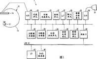
图1是显示根据本发明实施方案的X射线诊断装置的配置的图;FIG. 1 is a diagram showing the configuration of an X-ray diagnostic apparatus according to an embodiment of the present invention;
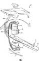
图2是图1中的X射线成像机构的透视图;Fig. 2 is a perspective view of the X-ray imaging mechanism in Fig. 1;
图3是显示该实施方案中的处理顺序的图;Fig. 3 is a diagram showing the processing sequence in this embodiment;
图4是显示根据本发明的一个改变的X射线诊断装置的配置的图;FIG. 4 is a diagram showing the configuration of a modified X-ray diagnostic apparatus according to the present invention;
具体实施方式Detailed ways
如图1中所示,X射线诊断装置包括X射线成像机构10和图像处理装置1。如图2中所示,X射线成像机构10包括X射线管12和X射线探测器14。X射线探测器14包括图像增强器15和TV照相机16。注意到代替图像增强器15和TV照相机16的组合,X射线探测器14可以包括具有以矩阵形式排列的半导体探测元件的平板探测器(FPD)。X射线管12连同X射线探测器14一起安装在C臂160上。在床顶部50上的对象P放置在X射线管12和X射线探测器14之间。C臂160被支承在从顶座163悬挂下来的弓形柱164上。C臂160可沿正交轴A,B和C旋转。As shown in FIG. 1 , the X-ray diagnostic apparatus includes an
图像处理装置1通过模拟/数字转换器(A/D)26连接到X射线探测器14。除了模拟/数字转换器(A/D)26外,图像处理装置1还包括控制单元27、输入设备28、2D图像存储器30、3D图像存储器29、过滤单元31、仿射变换单元32、图像分离单元33、位移识别单元34、图像组合单元35、网络卡36、查照表(LUT)37、数字/模拟转换器(D/A)38、显示器39,以及投影处理单元40。输入设备28具有用于输入用户指令以将血管路径图和当前X射线图像(最终X射线图像)组合的路径图开关。The
3D图像存储器29存储通过局域网(LAN)和网络卡36从外部X射线计算机化断层摄像装置43或PACS服务器45输入的与对象的目标区域关联的3D图像数据。3D图像数据典型地是注入有造影剂的对象的由X射线计算机化断层摄像装置43生成的血管增强的3D图像数据,即所谓的3D CTA(CT血管造影)图像数据。3D图像存储器29存储由图像分离单元33从3D CTA图像数据中分离的3D非血管图像数据和3D血管图像数据。3D血管图像数据具有可通过阈值处理提取的增强的血管区域。3D非血管数据具有不同于血管区域的与骨头和软组织关联的区域,其通过从3D CTA图像数据中减去3D血管图像数据而获得。The
2D图像存储器30存储由X射线成像机构10生成的2D X射线图像数据、受到过滤例如通过过滤单元31的高频增强的2D X射线图像数据、受到仿射变换例如通过仿射变换单元32的图像放大/运动的2D X射线图像数据、通过投影处理单元40的投影处理从3D血管图像数据中生成的血管投影图像数据、以及通过投影处理单元40的投影处理从非血管图像数据中生成的非血管投影图像数据。The
位移识别单元34根据当按下路径图开关时X射线成像机构10的成像姿势,计算通过投影处理单元40的投影处理而生成的非血管投影图像(在下文中如需要时称作位移识别图像)相对于当按下路径图开关时X射线成像机构10生成的2D X射线图像(在下文中称作最终X射线图像)的解剖学位移。注意到,成像姿势由C臂160相对于箭头A,B和C的角度(θA,θB和θC)和SID(X射线管12和等角点之间的距离)确定。另外,位移量定义为位移识别图像上的对象相对于最终X射线图像的解剖学空间误差的程度。更具体地,位移量定义为最终X射线图像和位移识别图像之间的图像放大率的差异、位移识别图像上的对象的非血管图像相对于最终X射线图像的空间位移量(称作位移量)、或者位移识别图像的投影角度相对于最终X射线图像的成像角度的位移量(角度差)。The
投影处理单元40通过根据成像姿势和计算的投影角度的位移量所确定的投影角度的投影处理从3D血管图像数据中生成血管投影图像(称作路径图)。仿射变换单元32执行该血管投影图像的放大处理,以获得放大率的匹配,并根据位移量移动图像(位移校正处理),以获得空间匹配。图像组合单元35组合已经历位移校正的路径图和最终X射线图像。在查照表37中,特定颜色被指定给该组合图像的路径图部分。显示器39显示组合图像。The
图3显示该实施方案中的处理流程。当输入检查信息例如病人姓名、特定病人号码(病人ID)、检查程序,以及检查日期时启动干预或医疗。关于相应对象(病人)的同一个区域的3D CTA数据通过网络41(例如LAN)从CT装置43、管理CT数据的PACS服务器45等装载到3D图像存储器29中。注意到3D CTA数据包含不同于血管的非血管区域的图像和用造影剂增强的血管区域的图像。为了描述方便,3D CTA数据将称为原始3D图像。Fig. 3 shows the processing flow in this embodiment. Intervention or medical treatment is initiated when examination information such as patient name, specific patient number (patient ID), examination procedure, and examination date is entered. 3D CTA data about the same area of the corresponding object (patient) is loaded into the
原始3D图像通过图像分离单元33基于CT值自动地分离成3D非血管图像和3D血管图像。典型地,通过阈值处理从原始3D图像中提取3D血管图像,并且通过从原始3D图像中减去3D血管图像提取3D非血管图像。3D血管图像数据和3D非血管图像数据存储到3D图像存储器29中。例如,对应于CT值120和CT值300之间间隔的数据从CTA数据中分离为3D血管图像,而其余数据被分离为3D非血管图像。这时,在3D非血管图像中,被识别为血管部分的区域(对应于CT值120和CT值300之间间隔的区域)被设置成例如0,作为软组织的标准CT值。注意到该CT值根据所使用的造影剂的浓度和类型、对比度情况等而改变。因此,优选地为每个地点设置CT值。The original 3D image is automatically separated into a 3D non-vascular image and a 3D blood vessel image by the
当启动干预或医疗处理时,导管被插入到血管中并被引导到目标位置,例如头部的血管。在该过程中,可能难以将导管插入到目标分支部分。在这种情况中,使用3D路径图,使得操作员可以把握分支部分的形状并容易地将导管插入到其中。When an intervention or medical treatment is initiated, a catheter is inserted into a blood vessel and guided to a target location, such as a blood vessel in the head. During this procedure, it may be difficult to catheterize into the target branch portion. In this case, a 3D road map is used so that the operator can grasp the shape of the branch portion and easily insert the catheter thereinto.
当操作员想要显示3D路径图时,他/她按下输入设备28的路径图按钮。由X射线成像机构10检测出的最终X射线图像显示在X射线图像显示器39上。当按下路径图按钮时,读出存储于3D图像存储器29中的对应3D非血管CTA数据。在该情况中,如果有针对多个检查的3D CTA图像(3D非血管图像数据和3D血管图像数据处理为一个检查数据),3D血管图像数据以缩略形式显示,并且操作员从缩略图中选择目标数据。选定的3D非血管图像数据提供到投影处理单元40。投影处理单元40在与X射线成像机构10的成像姿势(θA,θB,θC,SID)相同的投影角度(投影角度,SID)下通过执行3D非血管图像数据的投影处理生成非血管投影图像。此时,在生成CTA数据时,假设CTA图像的中心位于X射线光学系统的光轴(连接X射线管12的聚焦点到X射线探测器14中心的轴线)和在比床高D[cm]的平面之间的交叉点处,而生成投影图像。在该情况中,首先,投影处理单元40当将偏置值添加到CT值并将空气部分的值变换成0时生成投影图像。在该情况中,D表示将CTA图像的实际尺寸减小到1/2而获得的数据。另外,在生成投影图像时,生成投影数据使得投影图像的向上方向总是与病人头顶的方向一致。When the operator wants to display the 3D road map, he/she presses the road map button of the
位移识别单元34在下面两个步骤中识别非血管投影图像相对于最终X射线图像的位移量。在第一个步骤中,例如边缘增强过滤器应用于由过滤单元31和最终X射线图像生成的数据,并且首先通过使下面结果达到最小来确定近似放大率和位置:The
其中XE(i,j)和P(Mi+·i,Mj+·j)分别是边缘增强的最终X射线图像和边缘增强的非血管投影图像,N是图像的矩阵尺寸,M是非血管投影图像数据的图像放大率,(·i,··j)是位移向量,并且CR(M,·i,··j)是相关性计算的结果。当M从M1位移到M2以及·i和··j的每个从-·位移到··时获得相关性计算结果,并且使相关性计算结果达到最小的图像放大率和位移向量被确定。另外,r(x)被定义如下:where XE (i, j) and P(Mi+ i, Mj+ j) are the edge-enhanced final X-ray image and the edge-enhanced non-vascular projection image, respectively, N is the matrix size of the image, and M is the non-vascular projection image data The image magnification ratio of , (·i, ··j) is the displacement vector, and CR(M, ·i, ··j) is the result of the correlation calculation. Correlation calculation results are obtained when M is shifted from M1 to M2 and each of i and j is shifted from - to , and the image magnification and displacement vector that minimize the correlation calculation results are determined . Additionally, r(x) is defined as follows:
在该情况中,将基于假设(M0·i0··j0)是在CR(M,·i,··j)达到最小时的情况来描述下面处理。In this case, the following processing will be described based on the assumption that (M0 ·i0 ··j0 ) is the case when CR(M, ·i, ··j) reaches the minimum.
在第二个步骤中,除了在第一步骤中近似确定的放大率和位移量外,投影角度位移被确定。虽然可以机械地获得投影角度,它可能经常根据成像操作中的姿势、机械误差等而变化。由于这个原因,当机械测量的投影角度(θRL,θOC)从-Δθ位移到Δθ以及M、·i和··j位移时,以和方程式(1)相同的方式获得相关性计算结果,并且使相关性计算结果达到最小的投影角度、图像放大率和位移向量被确定。注意到因为已在第一步骤中在一定程度上对·,·i,和··j进行全局查找,当对应值在较窄范围内细微地移动时执行估算。In the second step, the projection angular displacement is determined in addition to the magnification and displacement approximately determined in the first step. Although the projection angle can be obtained mechanically, it may often vary according to posture, mechanical error, etc. in the imaging operation. For this reason, when the mechanically measured projected angles (θRL,θOC ) are shifted from -Δθ to Δθ and M, i, and j, the correlation calculation results are obtained in the same manner as equation (1), and The projection angle, image magnification, and displacement vector that minimize the correlation calculation result are determined. Note that since ·, ·i, and ··j have been somewhat globally looked up in the first step, the estimation is performed when the corresponding values move slightly within a narrow range.
当位移量被确定时,投影处理单元40根据由成像姿势确定的投影角度和所计算的投影角度位移量,通过投影处理从3D血管图像数据中生成血管投影图像(路径图)。仿射变换单元32执行该血管投影图像(路径图)的放大处理以允许与放大率匹配,并根据位移量移动图像以允许空间匹配。图像组合单元35将已经历位移校正的路径图和最终X射线图像进行组合。通过查找表37,色彩被指定给组合图像。结果生成的图像显示在显示器39上。When the displacement amount is determined, the
当重新进行X射线图像的获取时(透视重新进行),X射线图像由实时图像代替。此时,一般X射线图像显示在一个显示器上,并且组合图像显示在另一个显示器上。与另一个显示器上的图像组合的X射线图像受到类似的图像处理(首先反转,然后受到低频减少过滤)。When the acquisition of X-ray images is re-performed (fluoroscopy re-performed), the X-ray images are replaced by real-time images. At this time, the general X-ray image is displayed on one display, and the combined image is displayed on the other display. The X-ray image combined with the image on another monitor is subjected to similar image processing (first inverted, then subjected to low frequency reduction filtering).
如果在检查过程中病人移动,停止X射线图像获取,并且按下校准按钮。最终检测出的X射线图像和对应的非血管图像再次发送到位移识别单元34等,并重新进行第二个步骤。在执行第二个步骤之后,位移量被传送到图像组合单元35,从而允许以和上述相同的方式生成路径图。If the patient moves during the examination, the X-ray image acquisition is stopped and the calibration button is pressed. The finally detected X-ray images and corresponding non-vascular images are sent to the
注意到提供了自动和手动校准模式。当选择手动模式时,通过首先反转X射线图像然后对它实施边缘增强过滤而获得的图像,以及通过对基于当前时点的位移量投影非血管图像所获得的数据实施边缘增强过滤而获得的图像以不同颜色组合/显示。操作员可以在观察组合显示窗口时细微地调节投影角度、图像放大率,以及位移向量。Note that automatic and manual calibration modes are provided. When manual mode is selected, an image obtained by first inverting an X-ray image and then applying edge enhancement filtering to it, and an image obtained by applying edge enhancement filtering to data obtained by projecting a non-vascular image based on the amount of displacement at the current time point Images are combined/displayed in different colors. The operator can fine-tune the projection angle, image magnification, and displacement vector while viewing the composite display window.
(第一变型)(first variant)
在上面的实施方案中,图像组合单元35将由3D血管图像数据表示的投影图像和X射线图像组合到一个窗口中并显示它。但是,血管投影图像(路径图)可以放置和显示在相邻于X射线图像的上下、左右侧。此时,另外,导丝或导管的末端部分可以从X射线图像中探测到,并且所探测到的位置可以在路径图上叠加并显示为闪烁点。在该情况中,以不同的颜色叠加路径图和闪亮点可以改善可视性。用于导丝或导管的末端探测装置可以通过匹配过滤或通过使用导管标志提取导丝末端部分的数据,或者可以通过使用最近研发的具有GPS功能的导管来提取末端部分。In the above embodiment, the
(第二变型)(second variant)
在上面的实施方案中,图像组合单元35将由3D血管图像数据表示的投影图像(路径图)和X射线图像组合到一个窗口中并显示它。但是,本发明并不局限于此。3D非血管图像数据、3D血管图像数据以及X射线图像被传送到图像组合单元,并且首先通过使用3D非血管图像数据和X射线图象生成下面的图像:In the above embodiment, the
S(i,j) =X(i,j)+α×B(i,j)-N (3)S(i,j)=X(i,j)+α×B(i,j)-N (3)
其中X(i,j)和B(i,j)是X射线图像和由3D非血管图像数据表示的投影图像(路径图),并且α和N分别是表示透明度和亮度的参数。首先,使用预先确定的参数。如果需要,可以调节这些参数。如果操作员想要察看骨头的信息,α可被约减。如果操作员想以低密度显示骨头,可以增加α(但是,注意到如果α增加太多的话,3D非血管图像数据的信息变成占优势)。增加N使得整体图像变暗,反之亦然。S(i,j)基本上表示X射线图像。通过调节α和N,X射线图像可以不改变或以低密度显示。最后,该图像与通过将S(i,j)彩色化而获得的血管投影图像组合并代替在第一实施方案中受到图像处理的X射线图像被显示。where X(i,j) and B(i,j) are X-ray images and projection images (road maps) represented by 3D non-vascular image data, and α and N are parameters representing transparency and brightness, respectively. First, use predetermined parameters. These parameters can be adjusted if desired. α can be reduced if the operator wants to view bone information. If the operator wants to display bones at low density, alpha can be increased (however, note that if alpha is increased too much, the information of the 3D non-vascular image data becomes dominant). Increasing N makes the overall image darker, and vice versa. S(i,j) basically represents an X-ray image. By adjusting α and N, the X-ray image can be displayed unchanged or with low density. Finally, this image is combined with the vessel projection image obtained by colorizing S(i,j) and displayed instead of the X-ray image subjected to image processing in the first embodiment.
(第三变型)(third variant)
在上面的实施方案中,图像组合单元35将由3D血管图像数据表示的投影图像和X射线图像组合到一个图像中并显示它。但是,通过将3D非血管图像数据、3D血管图像数据和X射线图像传送到图像组合单元来显示3D血管图像数据和X射线之间的关联图像,以及同时以不同颜色组合并显示由3D非血管图像数据表示的投影图像和反转X射线投影图像允许操作员在检查定位准确性时参考3D路径图。另外,关于第一实施方案中的手动校正装置,操作员可以基于该组合图像确定是否需要手动校正。In the above embodiment, the
(第四变型)(fourth variant)
在第三变型中,由3D非血管图像数据表示的投影图像和反转X射线投影图像以不同颜色组合。但是,边缘增强处理可以应用于由3D非血管图像数据表示的投影图像和反转X射线投影图像上,并且两个边缘增强的图像可以用不同颜色组合并显示。位置关系位移在边缘部分处被显著地识别。也就是,增强这一信息使得方便地把握位移成为可能。In a third modification, the projection image represented by the 3D non-vascular image data and the reverse X-ray projection image are combined in different colors. However, edge enhancement processing can be applied to the projection image and the inverse X-ray projection image represented by 3D non-vascular image data, and the two edge-enhanced images can be combined and displayed in different colors. The positional relationship displacement is remarkably recognized at the edge portion. That is, enhancing this information makes it possible to easily grasp the displacement.
(第五变型)(fifth variant)
在第三变型中,由3D非血管图像数据表示的投影图像和反转X射线投影图像以不同颜色组合。但是,由3D非血管图像数据表示的投影图像和反转X射线投影图像可以从彼此中减去,并且可以显示结果生成的图像。通过它们之间的差异,也可以有效地把握位置关系位移。显示这一信息使得方便地把握位移成为可能。In a third modification, the projection image represented by the 3D non-vascular image data and the reverse X-ray projection image are combined in different colors. However, the projection image and the inverse X-ray projection image represented by the 3D non-vascular image data may be subtracted from each other and the resulting image may be displayed. Through the difference between them, the positional relationship displacement can also be effectively grasped. Displaying this information makes it possible to easily grasp the displacement.
(第六变型)(sixth variant)
图4显示根据第六变型的系统的布局。将省略与第一实施方案相同的部分的描述。图像重构单元47基于由X射线成像机构10以不同成像姿势重复获取的多个X射线图像重构3D图像。有三种3D重构模式:基于旋转DA图像(旋转数字血管图像)执行重构操作的3D-DA模式;通过使用旋转DSA图像的强反差序列(旋转数字减法血管图像)执行重构处理的伪3D-DA模式;以及分别从旋转DSA图像中重构3D血管图像和从旋转DSA掩蔽序列中重构3D非血管图像的模式。Figure 4 shows the layout of a system according to a sixth variant. Description of the same parts as those of the first embodiment will be omitted. The
图像重构单元47执行3D重构。在第一个步骤中,执行减法。当要重构旋转DSA图像时,从掩蔽图像中减去处于相应角度的强反差图像。对于对应其它成像角度的图像,从相应数据中减去校准数据。在该情况中,校准数据是用于校正探测器的灵敏度和X射线分布的数据并且预先获得。作为重构方法的例子,将在下面描述Feldkamp等人提出的过滤背投影方法。类似于Shepp & Logan或Ramachandran使用过的合适的卷积过滤器应用于200帧的减法图像。然后对于图像执行背投影计算以获得重构数据。在该情况中,重构区域定义为在X射线管的所有方向上与X射线束内切的圆柱体。该圆柱体的内部必须根据投影到探测器一个探测元件宽度上的重构区域的中心部分的长度d经历3D离散化,并且重构的图像必须从离散点处的数据中获得。该离散化间隔是例子,可以根据装置和制造者而改变。因此,基本上可以使用由每个装置确定的离散化间隔。The
对于每种模式如下处理重构好的图像。For each mode the reconstructed images are processed as follows.
1)3D-DA模式/伪3D-DA模式1) 3D-DA mode/pseudo 3D-DA mode
类似CTA图像,重构好的3D-DA图像或伪3D-DA图像以和上述相同的方式通过图像分离单元33分离成3D非血管图像和3D血管图像。然后这些图像发送到3D图像存储器29。注意到3D-DA模式的血管提取阈值在此时设置,并且通过使用该阈值提取3D血管图像。Like a CTA image, a reconstructed 3D-DA image or a pseudo 3D-DA image is separated into a 3D non-vascular image and a 3D blood vessel image by the
2)分开的重构模式2) Separate refactoring patterns
3D非血管图像和3D血管图像作为一对发送到3D图像存储器29。位移识别和图像组合以和CTA中相同的方式执行。The 3D non-vascular image and the 3D vascular image are sent to the
另外的优点和修改将容易被本领域技术人员想到。因此,本发明在其更广泛方面不局限于这里所显示和描述的具体细节和典型实施方案。因此,不背离本由附加权利要求及其等同物确定的一般发明概念的本质和范围可做出各种修改。Additional advantages and modifications will readily occur to those skilled in the art. Therefore, the invention in its broader aspects is not limited to the specific details and typical embodiments shown and described herein. Accordingly, various modifications may be made without departing from the spirit and scope of the general inventive concept as defined by the appended claims and their equivalents.
Claims (27)
Applications Claiming Priority (2)
| Application Number | Priority Date | Filing Date | Title |
|---|---|---|---|
| US11/362,738US7412023B2 (en) | 2006-02-28 | 2006-02-28 | X-ray diagnostic apparatus |
| US11/362,738 | 2006-02-28 |
Publications (2)
| Publication Number | Publication Date |
|---|---|
| CN101028194Atrue CN101028194A (en) | 2007-09-05 |
| CN101028194B CN101028194B (en) | 2010-05-12 |
Family
ID=38443988
Family Applications (1)
| Application Number | Title | Priority Date | Filing Date |
|---|---|---|---|
| CN2006100916812AActiveCN101028194B (en) | 2006-02-28 | 2006-06-09 | X-ray diagnostic device |
Country Status (3)
| Country | Link |
|---|---|
| US (1) | US7412023B2 (en) |
| JP (1) | JP4901531B2 (en) |
| CN (1) | CN101028194B (en) |
Cited By (9)
| Publication number | Priority date | Publication date | Assignee | Title |
|---|---|---|---|---|
| CN102048548A (en)* | 2009-10-29 | 2011-05-11 | 株式会社东芝 | X-ray imaging apparatus |
| CN102258379A (en)* | 2010-05-28 | 2011-11-30 | 株式会社东芝 | X-ray imaging apparatus |
| CN102525537A (en)* | 2009-02-23 | 2012-07-04 | 株式会社东芝 | Medical image processing apparatus and medical image processing method |
| CN101766489B (en)* | 2008-12-25 | 2012-10-10 | 株式会社东芝 | X-ray diagnostic apparatus |
| CN105007818A (en)* | 2013-02-27 | 2015-10-28 | 株式会社东芝 | X-ray diagnostic device and image processing device |
| CN105078402A (en)* | 2014-05-15 | 2015-11-25 | 株式会社东芝 | X-ray diagnostic apparatus |
| CN105144241A (en)* | 2013-04-10 | 2015-12-09 | 皇家飞利浦有限公司 | Image quality index and/or imaging parameter recommendation based thereon |
| CN104780833B (en)* | 2012-11-29 | 2018-03-02 | 东芝医疗系统株式会社 | Blood flow function testing device and X-ray diagnostic device |
| CN113384822A (en)* | 2020-06-29 | 2021-09-14 | 上海联影医疗科技股份有限公司 | Limited angle imaging method and system |
Families Citing this family (25)
| Publication number | Priority date | Publication date | Assignee | Title |
|---|---|---|---|---|
| JP4936929B2 (en)* | 2007-02-28 | 2012-05-23 | 株式会社東芝 | X-ray diagnostic apparatus and image display method |
| CN101686822A (en)* | 2007-07-11 | 2010-03-31 | 皇家飞利浦电子股份有限公司 | Method for acquiring 3-dimensional images of coronary vessels, particularly of coronary veins |
| JP5319188B2 (en)* | 2007-07-18 | 2013-10-16 | 株式会社東芝 | X-ray diagnostic equipment |
| US8090171B2 (en)* | 2007-10-19 | 2012-01-03 | Siemens Medical Solutions Usa, Inc. | Image data subtraction system suitable for use in angiography |
| JP5075580B2 (en)* | 2007-10-30 | 2012-11-21 | 株式会社東芝 | X-ray diagnostic imaging equipment |
| JP5641736B2 (en)* | 2008-03-25 | 2014-12-17 | 株式会社東芝 | Medical image processing apparatus and X-ray diagnostic apparatus |
| EP2289047B1 (en)* | 2008-06-25 | 2012-03-07 | Koninklijke Philips Electronics N.V. | Localizing an object of interest in a subject |
| JP5652994B2 (en)* | 2008-09-26 | 2015-01-14 | 株式会社東芝 | X-ray diagnostic equipment |
| JP5433253B2 (en)* | 2009-02-24 | 2014-03-05 | 株式会社東芝 | X-ray diagnostic equipment |
| JP2011015761A (en)* | 2009-07-07 | 2011-01-27 | Toshiba Corp | X-ray diagnostic apparatus |
| DE102009037243A1 (en)* | 2009-08-12 | 2011-02-17 | Siemens Aktiengesellschaft | Method for highlighting objects in interventional angiographic examinations |
| US9541509B2 (en)* | 2010-03-26 | 2017-01-10 | Fujifilm Corporation | Radiation imaging apparatus, radiation imaging method, body movement measuring method, and body movement measuring program |
| DE102010013221B4 (en)* | 2010-03-29 | 2012-06-28 | Siemens Aktiengesellschaft | Method for highlighting objects in interventional angiographic examinations and device for carrying out the method |
| US8526694B2 (en) | 2010-05-25 | 2013-09-03 | Siemens Medical Solutions Usa, Inc. | Medical image processing and registration system |
| JP5707087B2 (en)* | 2010-10-14 | 2015-04-22 | 株式会社東芝 | Medical diagnostic imaging equipment |
| JP6242569B2 (en) | 2011-08-25 | 2017-12-06 | 東芝メディカルシステムズ株式会社 | Medical image display apparatus and X-ray diagnostic apparatus |
| WO2014084377A1 (en)* | 2012-11-29 | 2014-06-05 | 株式会社 東芝 | Circulatory function examination device and x-ray diagnostic device |
| JP2014195642A (en)* | 2013-03-08 | 2014-10-16 | 株式会社東芝 | X-ray diagnostic apparatus |
| JP6056569B2 (en)* | 2013-03-12 | 2017-01-11 | 株式会社島津製作所 | Radiography equipment |
| US9208559B1 (en)* | 2014-07-25 | 2015-12-08 | Siemens Aktiengesellschaft | Method and apparatus for gastric artery chemical embolization |
| JP6419551B2 (en)* | 2014-11-28 | 2018-11-07 | キヤノンメディカルシステムズ株式会社 | X-ray diagnostic apparatus, image processing apparatus, and image processing program |
| CN108024832A (en) | 2015-09-28 | 2018-05-11 | 富士胶片株式会社 | Projection mapping device |
| EP3973877A1 (en)* | 2020-09-28 | 2022-03-30 | Koninklijke Philips N.V. | Guidance for treatment of a chronic total occlusion |
| JP7413972B2 (en)* | 2020-10-15 | 2024-01-16 | 株式会社島津製作所 | X-ray imaging device and image processing method |
| JP2022167132A (en)* | 2021-04-22 | 2022-11-04 | 日本装置開発株式会社 | X-ray inspection device |
Family Cites Families (25)
| Publication number | Priority date | Publication date | Assignee | Title |
|---|---|---|---|---|
| JP4054402B2 (en)* | 1997-04-25 | 2008-02-27 | 株式会社東芝 | X-ray tomography equipment |
| US4029963A (en)* | 1976-07-30 | 1977-06-14 | The Board Of Trustees Of Leland Stanford Junior University | X-ray spectral decomposition imaging system |
| FR2645300B1 (en)* | 1989-03-29 | 1994-09-09 | Gen Electric Cgr | AUTOMATIC IMAGE RECORDING PROCESS |
| US5839440A (en)* | 1994-06-17 | 1998-11-24 | Siemens Corporate Research, Inc. | Three-dimensional image registration method for spiral CT angiography |
| JP3667813B2 (en)* | 1995-04-18 | 2005-07-06 | 株式会社東芝 | X-ray diagnostic equipment |
| JPH09149902A (en)* | 1995-12-01 | 1997-06-10 | Hitachi Medical Corp | Tomography and tomograph |
| JPH105213A (en)* | 1996-06-24 | 1998-01-13 | Hitachi Medical Corp | X-ray contrast examination apparatus |
| US6195450B1 (en)* | 1997-09-18 | 2001-02-27 | Siemens Corporate Research, Inc. | Methods and apparatus for controlling X-ray angiographic image acquisition |
| US6188744B1 (en)* | 1998-03-30 | 2001-02-13 | Kabushiki Kaisha Toshiba | X-ray CT apparatus |
| JP2000175897A (en)* | 1998-12-17 | 2000-06-27 | Toshiba Corp | X-ray CT system for surgery support |
| JP4473358B2 (en)* | 1999-01-21 | 2010-06-02 | 株式会社東芝 | Diagnostic equipment |
| US6711433B1 (en)* | 1999-09-30 | 2004-03-23 | Siemens Corporate Research, Inc. | Method for providing a virtual contrast agent for augmented angioscopy |
| ES2180486T3 (en)* | 2000-05-09 | 2003-02-16 | Brainlab Ag | METHOD OF RECORDING IMAGE DATA OF A PATIENT RESULTING FROM A NAVIGATION METHOD, FOR SURGICAL OPERATIONS WITH X-RAYS. |
| FR2813973B1 (en)* | 2000-09-08 | 2003-06-20 | Ge Med Sys Global Tech Co Llc | METHOD AND DEVICE FOR GENERATING THREE-DIMENSIONAL IMAGES AND APPARATUS FOR RADIOLOGY THEREOF |
| JP4854137B2 (en)* | 2001-06-21 | 2012-01-18 | 株式会社東芝 | Medical diagnostic imaging equipment |
| US7130457B2 (en)* | 2001-07-17 | 2006-10-31 | Accuimage Diagnostics Corp. | Systems and graphical user interface for analyzing body images |
| US7127090B2 (en)* | 2001-07-30 | 2006-10-24 | Accuimage Diagnostics Corp | Methods and systems for combining a plurality of radiographic images |
| DE10162272A1 (en)* | 2001-12-19 | 2003-07-10 | Philips Intellectual Property | Procedure to support orientation in the vascular system |
| US6614874B2 (en)* | 2002-01-28 | 2003-09-02 | Ge Medical Systems Global Technology Company, Llc | Robust and efficient decomposition algorithm for digital x-ray de imaging |
| US6661873B2 (en)* | 2002-01-28 | 2003-12-09 | Ge Medical Systems Global Technology Company, Llc | Motion artifacts reduction algorithm for two-exposure dual-energy radiography |
| JP4172753B2 (en)* | 2002-04-03 | 2008-10-29 | 東芝医用システムエンジニアリング株式会社 | X-ray imaging device |
| JP4714677B2 (en)* | 2003-03-14 | 2011-06-29 | コーニンクレッカ フィリップス エレクトロニクス エヌ ヴィ | Motion compensated 3D volume imaging method |
| US7432924B2 (en)* | 2003-08-28 | 2008-10-07 | Kabushiki Kaisha Toshiba | 3D digital subtraction angiography image processing apparatus |
| US7450743B2 (en)* | 2004-01-21 | 2008-11-11 | Siemens Medical Solutions Usa, Inc. | Method and system of affine registration of inter-operative two dimensional images and pre-operative three dimensional images |
| US7035371B2 (en)* | 2004-03-22 | 2006-04-25 | Siemens Aktiengesellschaft | Method and device for medical imaging |
- 2006
- 2006-02-28USUS11/362,738patent/US7412023B2/enactiveActive
- 2006-06-09CNCN2006100916812Apatent/CN101028194B/enactiveActive
- 2007
- 2007-02-28JPJP2007050786Apatent/JP4901531B2/enactiveActive
Cited By (15)
| Publication number | Priority date | Publication date | Assignee | Title |
|---|---|---|---|---|
| US8475041B2 (en) | 2008-12-25 | 2013-07-02 | Kabushiki Kaisha Toshiba | X-ray diagnostic apparatus |
| CN101766489B (en)* | 2008-12-25 | 2012-10-10 | 株式会社东芝 | X-ray diagnostic apparatus |
| US9330481B2 (en) | 2009-02-23 | 2016-05-03 | Kabushiki Kaisha Toshiba | Medical image processing apparatus and medical image processing method |
| CN102525537A (en)* | 2009-02-23 | 2012-07-04 | 株式会社东芝 | Medical image processing apparatus and medical image processing method |
| CN102048548B (en)* | 2009-10-29 | 2014-10-01 | 株式会社东芝 | X-ray photography device |
| US8542902B2 (en) | 2009-10-29 | 2013-09-24 | Kabushiki Kaisha Toshiba | X-ray imaging apparatus |
| CN102048548A (en)* | 2009-10-29 | 2011-05-11 | 株式会社东芝 | X-ray imaging apparatus |
| CN102258379A (en)* | 2010-05-28 | 2011-11-30 | 株式会社东芝 | X-ray imaging apparatus |
| CN104780833B (en)* | 2012-11-29 | 2018-03-02 | 东芝医疗系统株式会社 | Blood flow function testing device and X-ray diagnostic device |
| CN105007818A (en)* | 2013-02-27 | 2015-10-28 | 株式会社东芝 | X-ray diagnostic device and image processing device |
| CN105007818B (en)* | 2013-02-27 | 2018-05-18 | 东芝医疗系统株式会社 | X-ray diagnostic device and image processing device |
| CN105144241A (en)* | 2013-04-10 | 2015-12-09 | 皇家飞利浦有限公司 | Image quality index and/or imaging parameter recommendation based thereon |
| CN105144241B (en)* | 2013-04-10 | 2020-09-01 | 皇家飞利浦有限公司 | Image quality index and/or imaging parameter recommendation based thereon |
| CN105078402A (en)* | 2014-05-15 | 2015-11-25 | 株式会社东芝 | X-ray diagnostic apparatus |
| CN113384822A (en)* | 2020-06-29 | 2021-09-14 | 上海联影医疗科技股份有限公司 | Limited angle imaging method and system |
Also Published As
| Publication number | Publication date |
|---|---|
| CN101028194B (en) | 2010-05-12 |
| US20070201609A1 (en) | 2007-08-30 |
| JP4901531B2 (en) | 2012-03-21 |
| US7412023B2 (en) | 2008-08-12 |
| JP2007229473A (en) | 2007-09-13 |
Similar Documents
| Publication | Publication Date | Title |
|---|---|---|
| CN101028194A (en) | X-ray diagnostic apparatus | |
| CN101529475B (en) | Presentation of 3D images in combination with 2D projection images | |
| US6721590B2 (en) | Medical image processing apparatus | |
| US6845142B2 (en) | Image processing involving correction of beam hardening | |
| US7103136B2 (en) | Fluoroscopic tomosynthesis system and method | |
| US7269246B2 (en) | X-ray angiography apparatus | |
| US7751523B2 (en) | X-ray diagnostic apparatus | |
| JP4495926B2 (en) | X-ray stereoscopic reconstruction processing apparatus, X-ray imaging apparatus, X-ray stereoscopic reconstruction processing method, and X-ray stereoscopic imaging auxiliary tool | |
| JP2009022754A (en) | Method for correcting registration of radiography images | |
| US20110037761A1 (en) | System and method of time-resolved, three-dimensional angiography | |
| US20190076103A1 (en) | Systems and methods for ultra low dose ct fluoroscopy | |
| JP4740348B2 (en) | X-ray diagnostic equipment | |
| CN112006704B (en) | Method and C-arm X-ray apparatus for creating 3D DSA images | |
| CN110876627B (en) | X-ray imaging device and X-ray image processing method | |
| JP7267329B2 (en) | Method and system for digital mammography imaging | |
| CN114469153A (en) | Angiography device and equipment based on CT (computed tomography) image and computer readable medium | |
| Navab et al. | Camera-augmented mobile C-arm (CAMC) application: 3D reconstruction using a low-cost mobile C-arm | |
| JP4828920B2 (en) | 3D image processing device | |
| Wink et al. | Intra-procedural coronary intervention planning using hybrid 3-dimensional reconstruction techniques1 | |
| JP5433253B2 (en) | X-ray diagnostic equipment | |
| Andersson et al. | 3D multimodality roadmapping in interventional neuroradiology |
Legal Events
| Date | Code | Title | Description |
|---|---|---|---|
| C06 | Publication | ||
| PB01 | Publication | ||
| C10 | Entry into substantive examination | ||
| SE01 | Entry into force of request for substantive examination | ||
| C14 | Grant of patent or utility model | ||
| GR01 | Patent grant |