CN101026861A - Method for establishing connection between mobile station and evolution packet core network - Google Patents
Method for establishing connection between mobile station and evolution packet core networkDownload PDFInfo
- Publication number
- CN101026861A CN101026861ACNA2006100080410ACN200610008041ACN101026861ACN 101026861 ACN101026861 ACN 101026861ACN A2006100080410 ACNA2006100080410 ACN A2006100080410ACN 200610008041 ACN200610008041 ACN 200610008041ACN 101026861 ACN101026861 ACN 101026861A
- Authority
- CN
- China
- Prior art keywords
- connection
- message
- network
- protocol
- access network
- Prior art date
- Legal status (The legal status is an assumption and is not a legal conclusion. Google has not performed a legal analysis and makes no representation as to the accuracy of the status listed.)
- Pending
Links
Images


Landscapes
- Mobile Radio Communication Systems (AREA)
Abstract
Translated fromChinese
Description
Translated fromChinese技术领域technical field
本发明涉及移动通信网络接入技术,尤指一种在演进网络(EvolvedNetwork)中,移动台与演进分组核心网间连接建立的方法。The invention relates to a mobile communication network access technology, in particular to a method for establishing a connection between a mobile station and an evolved packet core network in an evolved network (Evolved Network).
背景技术Background technique
通用移动通信系统(UMTS)是第三代合作伙伴计划(3GPP)组织定义的一种第三代无线通信网络技术标准,该标准发布了REL-99、REL-4、REL-5和REL-6版本。UMTS网络由核心网(Core Network)和UTMS陆地无线接入网(UTRAN,UMTS Terrestrial Radio Access Network)组成。核心网包括电路域(CS,Circuit Switch)和分组域(PS,Packet Switch)两个部分,其中,电路域提供基于电路交换的业务如语音业务,而分组域提供基于分组交换的业务如因特网(Internet)访问。UMTS网络中用户使用的终端为用户设备(UE,User Equipment)。Universal Mobile Telecommunications System (UMTS) is a third-generation wireless communication network technology standard defined by the Third Generation Partnership Project (3GPP), which released REL-99, REL-4, REL-5 and REL-6 Version. The UMTS network consists of a core network (Core Network) and a UTMS Terrestrial Radio Access Network (UTRAN, UMTS Terrestrial Radio Access Network). The core network includes two parts, the circuit domain (CS, Circuit Switch) and the packet domain (PS, Packet Switch), wherein the circuit domain provides services based on circuit switching such as voice services, while the packet domain provides services based on packet switching such as the Internet ( Internet) access. A terminal used by a user in a UMTS network is a user equipment (UE, User Equipment).
图1是现有技术UMTS的网络结构示意图,如图1所示,由于本文只涉及分组域部分,因此核心网中电路域部分未在图1中示出,核心网由服务GPRS支持节点(SGSN)、网关GPRS支持节点(GGSN)和归属位置寄存器(HLR)组成;接入网由无线网络控制器(RNC)和基站NodeB组成。UE通过Uu接口与NodeB间进行交互,每个RNC可以连接若干NodeB,每个SGSN可以连接若干RNC。NodeB与RNC之间为Iub接口、RNC与SGSN之间为Iu接口、SGSN与GGSN之间为Gn/Gp接口、SGSN与HLR之间为Gr接口、GGSN与HLR之间为Gc接口、GGSN与外部的分组数据网络(PDN,Packet Data Network)之间为Gi接口,本文中PDN是指所有分组数据网络的总称,它可以是Internet网络或企业网络等等。Fig. 1 is a schematic diagram of the network structure of the prior art UMTS, as shown in Fig. 1, since this paper only involves the packet domain part, the circuit domain part in the core network is not shown in Fig. 1, and the core network is composed of Serving GPRS Support Node (SGSN ), gateway GPRS support node (GGSN) and home location register (HLR); the access network is composed of radio network controller (RNC) and base station NodeB. The UE interacts with the NodeB through the Uu interface. Each RNC can connect to several NodeBs, and each SGSN can connect to several RNCs. Iub interface between NodeB and RNC, Iu interface between RNC and SGSN, Gn/Gp interface between SGSN and GGSN, Gr interface between SGSN and HLR, Gc interface between GGSN and HLR, GGSN and external The packet data network (PDN, Packet Data Network) is a Gi interface. In this paper, PDN refers to the general term of all packet data networks, which can be Internet networks or enterprise networks.
其中,Uu接口是UMTS网络的空中接口。物理层(PHY或L1)协议位于NodeB,属于Uu接口的第一层协议;媒体接入控制(MAC)协议、无线链路控制(RLC)协议、分组数据会聚协议(PDCP)和广播/多播控制协议(BMC,Broadcast/Multicast Control)位于RNC,属于Uu接口的第二层协议;无线资源管理(RRC)协议位于RNC,属于Uu接口的第三层协议。PHY协议主要完成物理信道的处理、发射和接收物理信道;MAC协议主要完成逻辑信道到传输信道的映射和调度功能;RLC协议主要完成数据的分段/重组和重发;PDCP主要完成数据的IP头压缩/解压缩以及维护数据的序列号;BMC协议主要完成小区广播消息的缓存和调度;而RRC协议是Uu接口的核心,RRC协议负责无线资源的管理,完成对下层协议PHY/MAC/RLC/PDCP/BMC的配置和控制。Wherein, the Uu interface is an air interface of the UMTS network. The physical layer (PHY or L1) protocol is located at NodeB and belongs to the first layer protocol of the Uu interface; media access control (MAC) protocol, radio link control (RLC) protocol, packet data convergence protocol (PDCP) and broadcast/multicast The control protocol (BMC, Broadcast/Multicast Control) is located in the RNC and belongs to the second layer protocol of the Uu interface; the radio resource management (RRC) protocol is located in the RNC and belongs to the third layer protocol of the Uu interface. The PHY protocol mainly completes the processing, transmission and reception of physical channels; the MAC protocol mainly completes the mapping and scheduling functions from logical channels to transmission channels; the RLC protocol mainly completes data segmentation/reassembly and retransmission; PDCP mainly completes data IP Header compression/decompression and serial number maintenance data; BMC protocol mainly completes the buffering and scheduling of cell broadcast messages; RRC protocol is the core of Uu interface, RRC protocol is responsible for the management of wireless resources, and completes the lower layer protocol PHY/MAC/RLC /PDCP/BMC configuration and control.
Iu接口是接入网与核心网的关键接口,无线资源的管理和控制被Iu接口隔离在接入网内,使得核心网只关注业务的提供。Iu接口包括控制面协议和用户面协议,控制面协议主要完成信令消息的交互和处理,用户面协议主要完成用户数据的传送。R99和R4版本的Iu接口采用ATM传输技术,从R5版本开始,Iu接口既可以采用异步传输模式(ATM,Asynchronous Transfer Mode)传输技术也可以采用IP传输技术。当采用IP传输技术时,RNC、SGSN之间可采用IP承载网络如以太网提供信令和业务数据的传输。The Iu interface is the key interface between the access network and the core network. The management and control of radio resources is isolated in the access network by the Iu interface, so that the core network only focuses on service provision. The Iu interface includes a control plane protocol and a user plane protocol. The control plane protocol mainly completes the interaction and processing of signaling messages, and the user plane protocol mainly completes the transmission of user data. The Iu interface of the R99 and R4 versions adopts the ATM transmission technology. Starting from the R5 version, the Iu interface can adopt either the Asynchronous Transfer Mode (ATM, Asynchronous Transfer Mode) transmission technology or the IP transmission technology. When the IP transmission technology is adopted, an IP bearer network such as Ethernet can be used between the RNC and the SGSN to provide signaling and service data transmission.
图2是UMTS中,3GPP定义的采用IP传输技术的Iu接口的协议栈示意图,如图2所示,Iu接口在横向上被划分为两层:无线网络层和传输网络层,其中,无线网络层负责处理与无线技术有关的功能,而传输网络层负责处理与传输技术有关的功能;Iu接口在纵向上被划分为两个面:控制面和用户面。其中,控制面负责信令消息的交互、用户面承载链路的管理,用户面承载链路是指位于用户面的、用于传送用户分组数据的承载链路,比如GPRS隧道用户协议(GTP-U,GPRS Tunneling Protocol-User)隧道;用户面负责用户数据的封装和传送。Figure 2 is a schematic diagram of the protocol stack of the Iu interface using IP transmission technology defined by 3GPP in UMTS. As shown in Figure 2, the Iu interface is divided into two layers in the horizontal direction: the wireless network layer and the transmission network layer, wherein the wireless network The layer is responsible for processing functions related to wireless technology, while the transport network layer is responsible for processing functions related to transmission technology; the Iu interface is vertically divided into two planes: the control plane and the user plane. Among them, the control plane is responsible for the interaction of signaling messages and the management of the user plane bearer link. The user plane bearer link refers to the bearer link located on the user plane and used to transmit user packet data, such as the GPRS Tunnel User Protocol (GTP- U, GPRS Tunneling Protocol-User) tunnel; the user plane is responsible for the encapsulation and transmission of user data.
如图2所示,控制面的无线网络层是无线接入网络应用部分(RANAP,Radio Access Network Application Part)协议,负责SGSN与RNC间无线网络层信令消息的交互;而用户面的无线网络层是Iu用户平面(Iu UP,Iu UserPlane)协议,负责用户数据的帧处理。在分组域,Iu UP采用透明模式,即Iu UP不对用户数据作任何处理,用户数据在Iu UP中透明传输,因此,也可以认为分组域Iu接口的用户面在无线网络层没有处理协议。As shown in Figure 2, the wireless network layer of the control plane is a Radio Access Network Application Part (RANAP, Radio Access Network Application Part) protocol, which is responsible for the interaction of wireless network layer signaling messages between the SGSN and the RNC; and the wireless network layer of the user plane The layer is the Iu User Plane (Iu UP, Iu UserPlane) protocol, which is responsible for frame processing of user data. In the packet domain, Iu UP adopts transparent mode, that is, Iu UP does not perform any processing on user data, and user data is transparently transmitted in Iu UP. Therefore, it can also be considered that the user plane of the Iu interface in the packet domain has no processing protocol at the wireless network layer.
控制面的传输网络层包括SCCP/M3UA/SCTP/IP/L1这些协议共同完成RANAP消息的路由和可靠传输。其中,信令连接控制部分(SCCP)协议可以向RANAP提供有连接和无连接两种服务,通常,与呼叫相关的RANAP消息使用SCCP提供的有连接服务来传送;而与呼叫无关的RANAP消息使用SCCP提供的无连接服务来传送,比如寻呼消息使用无连接的SCCP来传送。MTP3-用户适配层(M3UA)/流控制传输协议(SCTP)完成对SCCP消息的适配和路由,保证SCCP消息完整、正确、可靠地被传送到目的地。The transmission network layer of the control plane includes protocols such as SCCP/M3UA/SCTP/IP/L1 to complete the routing and reliable transmission of RANAP messages. Among them, the Signaling Connection Control Part (SCCP) protocol can provide RANAP with both connection and connectionless services. Usually, call-related RANAP messages are transmitted using the connection service provided by SCCP; and call-independent RANAP messages use The connectionless service provided by SCCP is used to transmit, for example, the paging message is transmitted using connectionless SCCP. MTP3-User Adaptation Layer (M3UA)/Stream Control Transmission Protocol (SCTP) completes the adaptation and routing of SCCP messages, ensuring that SCCP messages are transmitted to the destination completely, correctly and reliably.
用户面的传输网络层包括GTP-U/UPD/IP/L1协议,这些协议共同完成用户分组数据的传送。其中,GTP-U协议用于在传输网络中为用户的业务数据提供隧道传送,GTP-U数据由下层的用户数据报协议(UDP)/Internet协议(IP)协议承载。The transmission network layer of the user plane includes GTP-U/UPD/IP/L1 protocols, and these protocols jointly complete the transmission of user packet data. Among them, the GTP-U protocol is used to provide tunnel transmission for user service data in the transmission network, and the GTP-U data is carried by the lower-layer User Datagram Protocol (UDP)/Internet Protocol (IP) protocol.
通常,3GPP网络被划分为接入网和核心网两层,接入网为接入层(AS,Access Stratum),核心网为非接入层(NAS,NonAccess Stratum),UE与接入网交互的信令消息统称为AS消息,UE与核心网交互的信令消息统称为NAS消息。NAS消息包括与移动性管理相关的信令消息、与会话管理相关的信令消息,以及与短消息业务相关的信令消息。UE在开机附着、路由区更新、业务请求或寻呼响应时,需要与核心网中的SGSN进行信令交互,这些信令消息属于NAS消息。NAS消息在空中接口中作为非接入层协议数据单元(NAS-PDU)数据,携带在AS消息中传送。Usually, the 3GPP network is divided into two layers: the access network and the core network. The access network is the access stratum (AS, Access Stratum), and the core network is the non-access stratum (NAS, NonAccess Stratum). UE interacts with the access network. The signaling messages of the UE are collectively referred to as AS messages, and the signaling messages interacted between the UE and the core network are collectively referred to as NAS messages. NAS messages include signaling messages related to mobility management, signaling messages related to session management, and signaling messages related to short message services. When the UE starts attaching, routing area update, service request or paging response, it needs to perform signaling interaction with the SGSN in the core network, and these signaling messages belong to NAS messages. The NAS message is carried in the AS message as non-access stratum protocol data unit (NAS-PDU) data in the air interface.
UE与SGSN间进行信令交互之前,UE与SGSN需要建立信令连接,本文中信令连接可简称为连接,从而在通信各节点如RNC、SGSN中为UE建立通信上下文,同时为通信分配必要的资源,使得UE能够与SGSN进行信令消息的交互。建立信令连接包括:UE与RNC之间的RRC连接建立和RNC与SGSN之间的Iu连接建立两个过程。Before the signaling interaction between the UE and the SGSN, the UE and the SGSN need to establish a signaling connection. In this paper, the signaling connection can be referred to as a connection for short, so that a communication context is established for the UE in each communication node such as RNC and SGSN, and at the same time, necessary information is allocated for communication. resources, so that the UE can interact with the SGSN for signaling messages. Establishing a signaling connection includes: establishing an RRC connection between UE and RNC and establishing an Iu connection between RNC and SGSN.
图3是现有技术UE与SGSN间信令连接建立的流程图,在UE进行网络附着、路由区更新、分组业务呼叫或寻呼响应等时,UE需要与SGSN进行信令消息交互即NAS消息交互。在发送NAS消息之前,UE会检查自身是否已建立与RNC间的RRC连接,若没有建立,则执行以下步骤:Figure 3 is a flow chart of establishing a signaling connection between UE and SGSN in the prior art. When UE performs network attachment, routing area update, packet service call or paging response, etc., UE needs to exchange signaling messages with SGSN, that is, NAS message interact. Before sending the NAS message, the UE will check whether it has established an RRC connection with the RNC, and if not, perform the following steps:
步骤300~步骤301:UE向RNC发送RRC连接请求(RRC ConnectionRequest)消息,请求与RNC建立RRC连接;RNC收到RRC连接请求消息后,为UE建立通信上下文、分配并建立无线信道,之后,RNC向UE返回RRC连接建立(RRC Connection Setup)消息。Steps 300 to 301: UE sends an RRC connection request (RRC ConnectionRequest) message to RNC, requesting to establish an RRC connection with RNC; after receiving the RRC connection request message, RNC establishes a communication context for UE, allocates and establishes a wireless channel, and then, RNC Return an RRC Connection Setup (RRC Connection Setup) message to the UE.
步骤302:UE接收到RRC连接建立消息后,根据该RRC连接建立消息中携带的参数,创建并配置Uu接口各层协议,建立并激活上行信道,之后,UE向RNC返回RRC连接建立完成(RRC Connection Setup Complete)消息,以示RRC连接成功建立。Step 302: After the UE receives the RRC connection establishment message, according to the parameters carried in the RRC connection establishment message, it creates and configures protocols of various layers of the Uu interface, establishes and activates the uplink channel, and then returns the RRC connection establishment completion (RRC connection establishment completion) to the RNC from the UE. Connection Setup Complete) message to indicate that the RRC connection is successfully established.
上述步骤300~步骤302为RRC连接建立过程。The above steps 300 to 302 are the RRC connection establishment process.
步骤303:RRC连接成功建立之后,UE将NAS消息作为NAS-PDU数据携带在初始直接传送(Initial Direct Transfer)消息中发送给RNC。Step 303: After the RRC connection is successfully established, the UE sends the NAS message as NAS-PDU data in an Initial Direct Transfer (Initial Direct Transfer) message to the RNC.
该初始直接传送消息中会携带NAS-PDU数据的目的地信息,比如是分组核心网还是电路核心网,这里假设,NAS-PDU数据发送至分组核心网中的SGSN。The initial direct transfer message will carry the destination information of the NAS-PDU data, such as the packet core network or the circuit core network. It is assumed here that the NAS-PDU data is sent to the SGSN in the packet core network.
步骤304:RNC接收到携带有NAS-PDU数据的初始直接传送消息后,RNC会检查自身是否已建立与SGSN间的Iu连接,若没有建立,则RNC为Iu连接分配一个Iu连接标识;RNC将初始直接传送消息中的NAS-PDU数据读出,并重新封装在初始UE消息(Initial UE Message)中,同时在初始UE消息中携带所述Iu连接标识,RNC向SGSN发送初始UE消息;SGSN接收到初始UE消息后,为UE建立通信上下文,存储Iu连接标识和UE标识,为Iu连接分配必要的资源。Step 304: After the RNC receives the initial direct transfer message carrying the NAS-PDU data, the RNC will check whether itself has established an Iu connection with the SGSN, if not established, the RNC will distribute an Iu connection identifier for the Iu connection; the RNC will The NAS-PDU data in the initial direct transfer message is read out, and repackaged in the initial UE message (Initial UE Message), and at the same time, the Iu connection identifier is carried in the initial UE message, and the RNC sends the initial UE message to the SGSN; the SGSN receives After receiving the initial UE message, establish a communication context for the UE, store the Iu connection ID and UE ID, and allocate necessary resources for the Iu connection.
其中,初始UE消息是RANAP协议消息。在RNC中,RANAP请求下层的SCCP发送初始UE消息,并建立SCCP连接;RNC中的SCCP协议向SGSN中的SCCP发送连接请求(CR,Connection Request)消息,初始UE消息被封装成数据,携带在该连接请求消息中;SGSN中的SCCP接收到连接请求后,若接受SCCP连接建立请求,则向RNC返回一条连接确认(CC,Connection Confirm)消息。Wherein, the initial UE message is a RANAP protocol message. In the RNC, RANAP requests the SCCP of the lower layer to send an initial UE message and establish an SCCP connection; the SCCP protocol in the RNC sends a connection request (CR, Connection Request) message to the SCCP in the SGSN, and the initial UE message is encapsulated into data and carried in In the connection request message; after the SCCP in the SGSN receives the connection request, if it accepts the SCCP connection establishment request, it returns a connection confirmation (CC, Connection Confirm) message to the RNC.
上述步骤303~步骤304为Iu连接建立过程。The above steps 303 to 304 are the Iu connection establishment process.
至此,UE与SGSN之间的信令连接成功建立,UE与SGSN之间可以在该连接上交互信令消息。So far, the signaling connection between the UE and the SGSN is successfully established, and signaling messages can be exchanged between the UE and the SGSN on the connection.
在UE与SGSN间信令连接建立中,Iu连接是RNC和SGSN之间的RANAP信令连接,用于在Iu接口传送UE与SGSN交互的NAS信令消息和与呼叫相关的RANAP消息。RNC在发送第一条NAS消息给SGSN的同时,RNC与SGSN建立Iu连接。Iu连接建立后,与本次通信活动相关的所有RANAP消息以及UE与SGSN交互的NAS消息都使用该Iu连接来传送。In the establishment of signaling connection between UE and SGSN, Iu connection is a RANAP signaling connection between RNC and SGSN, which is used to transmit NAS signaling messages exchanged between UE and SGSN and call-related RANAP messages on the Iu interface. When the RNC sends the first NAS message to the SGSN, the RNC establishes an Iu connection with the SGSN. After the Iu connection is established, all RANAP messages related to this communication activity and NAS messages exchanged between the UE and the SGSN are transmitted using the Iu connection.
图4是现有技术Iu连接建立的流程图,图4所示流程图中,采用SCCPRNC表示位于RNC中的SCCP协议实体,SCCPSGSN表示位于SGSN中的SCCP协议实体,Iu连接建立包括以下步骤:Fig. 4 is the flow chart of prior art Iu connection establishment, in the flow chart shown in Fig. 4, adopt SCCPRNC to represent the SCCP protocol entity located in RNC, SCCPSGSN represents the SCCP protocol entity located in SGSN, Iu connection establishment comprises the following steps :
步骤400:SCCPRNC向SCCPSGSN发送SCCP连接请求(SCCP ConnectionRequest)消息,以建立SCCP连接。Step 400: The SCCPRNC sends an SCCP connection request (SCCP ConnectionRequest) message to the SCCPSGSN to establish an SCCP connection.
当RNC从无线接口收到第一条NAS消息,即第一条携带有NAS-PDU数据的无线资源管理(RRC)消息时,若UE与核心网间未建立Iu连接,则RNC中的RANAP请求下层SCCP发送初始UE消息(Initial UE Message),由于初始UE消息携带的NAS消息与呼叫相关,因此,RANAP同时指示在RNC与SGSN中的SCCP间建立SCCP连接。When the RNC receives the first NAS message from the radio interface, that is, the first radio resource management (RRC) message carrying NAS-PDU data, if the Iu connection is not established between the UE and the core network, the RANAP request in the RNC The lower layer SCCP sends an initial UE message (Initial UE Message). Since the NAS message carried in the initial UE message is related to the call, the RANAP simultaneously instructs the SCCP connection between the RNC and the SCCP in the SGSN.
一般,如果初始UE消息的长度小于或等于SCCP连接请求消息所能携带的数据的长度,则初始UE消息被携带在SCCP连接请求消息中发送给SGSN;如果初始UE消息的长度大于SCCP连接请求消息所能携带的数据的长度,则在SCCP连接建立之后,将初始UE消息携带在SCCP的数据传送(SCCP Data Transfer)消息中发送给SGSN。Generally, if the length of the initial UE message is less than or equal to the length of the data that the SCCP connection request message can carry, the initial UE message is carried in the SCCP connection request message and sent to the SGSN; if the length of the initial UE message is greater than the SCCP connection request message The length of the data that can be carried, after the SCCP connection is established, the initial UE message is carried in the SCCP Data Transfer (SCCP Data Transfer) message and sent to the SGSN.
RNC在将初始UE消息传递给SGSN之前,会为即将建立的Iu连接分配Iu连接标识,并在初始UE消息中携带以下信息:UE当前所在位置的服务区标识;UE的位置信息,如路由区标识或位置区标识;用于指示NAS消息的目的地是分组域中的SGSN还是电路域中的移动交换中心(MSC)的域标识;Iu连接标识;以及全球RNC标识。Before the RNC transmits the initial UE message to the SGSN, it will allocate an Iu connection identifier for the Iu connection to be established, and carry the following information in the initial UE message: the service area identifier of the current location of the UE; the location information of the UE, such as the routing area ID or location area ID; domain ID for indicating whether the destination of the NAS message is the SGSN in the packet domain or the mobile switching center (MSC) in the circuit domain; the Iu connection ID; and the global RNC ID.
步骤401:SCCPSGSN收到SCCP连接请求消息后,向SCCPRNC返回SCCP连接确认(SCCP Connection Confirm)消息。Step 401: After receiving the SCCP connection request message, the SCCPSGSN returns an SCCP connection confirmation (SCCP Connection Confirm) message to the SCCPRNC .
如果SCCP连接请求消息中携带有数据,比如封装的初始UE消息,SCCPSGSN将接收到的数据提交给上层的RANAP进行处理;If the SCCP connection request message carries data, such as the encapsulated initial UE message, the SCCPSGSN submits the received data to the upper layer RANAP for processing;
如果SCCP连接请求消息中未携带初始UE消息,那么,在SCCPRNC收到SCCP连接确认消息后,SCCPRNC将初始UE消息作为数据被携带在SCCP数据传送(SCCP Data Transfer)消息中,并发送给SCCPSGSN;SCCPSGSN将SCCP数据传送消息中携带的数据提交给上层的RANAP进行处理。If the initial UE message is not carried in the SCCP connection request message, then, after the SCCPRNC receives the SCCP connection confirmation message, the SCCPRNC carries the initial UE message as data in the SCCP data transfer (SCCP Data Transfer) message, and sends it to SCCPSGSN : The SCCPSGSN submits the data carried in the SCCP data transfer message to the upper layer RANAP for processing.
Iu连接建立成功后,RNC与SGSN之间交互的与本次通信活动相关的RANAP消息均由建立的SCCP连接来完成消息的传送,且使用SCCP数据传送消息来承载交互的RANAP消息。After the Iu connection is successfully established, the RANAP messages exchanged between the RNC and the SGSN related to this communication activity are transmitted by the established SCCP connection, and the SCCP data transfer messages are used to carry the exchanged RANAP messages.
如果SCCPSGSN拒绝SCCP连接建立请求,SCCPSGSN向SCCPRNC发送SCCP连接拒绝(SCCP Connection Reject)消息,以示Iu连接建立失败。If the SCCPSGSN rejects the SCCP connection establishment request, the SCCPSGSN sends an SCCP Connection Reject (SCCP Connection Reject) message to the SCCPRNC to indicate that the Iu connection establishment fails.
SGSN中的RANAP收到初始UE消息后,为UE创建通信上下文信息,存储消息中携带的信息,例如Iu连接标识、UE的位置信息、全球RNC标识,并将初始UE消息中携带的NAS消息提交给更上一层协议实体,比如GPRS移动性管理(GMM,GPRS Mobility Management)协议实体,或会话管理(Session Management)协议实体等。After receiving the initial UE message, the RANAP in the SGSN creates communication context information for the UE, stores the information carried in the message, such as the Iu connection identifier, UE location information, and global RNC identifier, and submits the NAS message carried in the initial UE message to For a higher-level protocol entity, such as a GPRS Mobility Management (GMM, GPRS Mobility Management) protocol entity, or a Session Management (Session Management) protocol entity, etc.
对于R99和R4版本,Iu接口基于ATM技术和七号信令系统(SS7,SignalingSystem7),传输网络层采用SCCP/MTP3b协议;对于R5版本的Iu接口,虽然可以支持IP传输技术,但考虑到后向兼容性,因此继续使用SCCP协议,同时引入M3UA和SCTP协议,这样,使得Iu接口的协议栈比较复杂,Iu接口的协议栈见图2所示。上述图4是基于现有技术图2的Iu接口建立过程。For the R99 and R4 versions, the Iu interface is based on ATM technology and No. 7 signaling system (SS7, SignalingSystem7), and the transmission network layer adopts the SCCP/MTP3b protocol; for the R5 version of the Iu interface, although it can support IP transmission technology, but considering the later Therefore, the SCCP protocol continues to be used, and the M3UA and SCTP protocols are introduced at the same time. In this way, the protocol stack of the Iu interface is more complicated. The protocol stack of the Iu interface is shown in Figure 2. The above FIG. 4 is based on the Iu interface establishment process of FIG. 2 in the prior art.
从上述现有UMTS中UE与SGSN间信令连接建立的方法可见:在RRC连接成功建立后,才建立Iu连接,最终实现UE与SGSN连接的建立,这样处理,增加了UE与SGSN间信令连接建立的时间。It can be seen from the method for establishing the signaling connection between the UE and the SGSN in the above-mentioned existing UMTS: after the RRC connection is successfully established, the Iu connection is established, and finally the establishment of the UE and the SGSN connection is realized. This process increases the signaling between the UE and the SGSN. The time the connection was established.
目前,3GPP正在研究UMTS网络演进后的下一代网络,并制定演进网络的技术标准,本文中将UMTS网络演进后的下一代网络简称为演进网络(Evolved Network)。演进网络将具有很多新的特点,比如:只提供分组型业务,语音、视频电话等实时业务也采用分组的方式来实现;实现全IP网络,网络中各节点通过IP网络互连,每个移动终端附着后分配IP地址;支持与UMTS网络之间的切换和漫游。除此之外,演进网络对接入和切换的时间提出了更高的要求:用户接入网络进入激活态的时间不超过200ms;实时业务的系统间切换时间不超过300毫秒;非实时业务的系统间切换时间不超过500毫秒等,可见,演进网络对快速接入的时间要求是比较苛刻的。At present, 3GPP is studying the next-generation network after UMTS network evolution, and formulating technical standards for the evolved network. In this paper, the next-generation network after the UMTS network evolution is referred to as the evolved network (Evolved Network). The evolved network will have many new features, such as: only packet-based services are provided, and real-time services such as voice and video telephony are also implemented in packets; an all-IP network is realized, and all nodes in the network are interconnected through the IP network. After the terminal is attached, the IP address is assigned; it supports handover and roaming with the UMTS network. In addition, the evolved network puts forward higher requirements on the access and switching time: the time for users to access the network to enter the active state shall not exceed 200ms; the switching time between systems for real-time services shall not exceed 300ms; The inter-system switching time does not exceed 500 milliseconds, etc. It can be seen that the evolution network has strict requirements on the fast access time.
图5是目前3GPP定义的演进网络的结构示意图,该演进网络结构还未最终确定。如图5所示,演进网络包括演进分组核心网(Evolved Packet Core)和演进无线接入网(Evolved-RAN,Radio Access Network)。其中,EvolvedPacket Core中有三个逻辑功能实体,移动性管理实体(MME,MobilityManagement Entity)、用户面实体(UPE,User Plane Entity)和接入系统间锚点(Inter AS Anchor),MME用于实现移动性管理,UPE用于实现分组会话管理和用户面分组数据的处理,Inter AS Anchor用于实现演进网络与外部PDN的接入、演进网络与其他非3GPP网络如无线局域网(WLAN)之间的切换和漫游等;Evolved-RAN实现空中接口的功能,Evolved RAN与EvolvedPacket Core之间的接口为S1接口,而Inter AS Anchor与PDN的接口为Gi接口。目前,3GPP未定义如何实现S1接口。本发明中,将演进网络中用户使用的终端设备统一称为移动台(MS,Mobile Station)。FIG. 5 is a schematic structural diagram of an evolved network defined by the 3GPP at present, and the structure of the evolved network has not yet been finalized. As shown in Figure 5, the evolved network includes an evolved packet core network (Evolved Packet Core) and an evolved radio access network (Evolved-RAN, Radio Access Network). Among them, there are three logical functional entities in EvolvedPacket Core, Mobility Management Entity (MME, Mobility Management Entity), User Plane Entity (UPE, User Plane Entity) and Inter AS Anchor (Inter AS Anchor), MME is used to realize mobile UPE is used to realize packet session management and user plane packet data processing, Inter AS Anchor is used to realize the access of the evolved network and external PDN, and the handover between the evolved network and other non-3GPP networks such as wireless local area network (WLAN) and roaming, etc.; Evolved-RAN realizes the air interface function, the interface between Evolved RAN and EvolvedPacket Core is S1 interface, and the interface between Inter AS Anchor and PDN is Gi interface. Currently, 3GPP does not define how to implement the S1 interface. In the present invention, the terminal devices used by users in the evolved network are collectively referred to as mobile stations (MS, Mobile Station).
如图5中所示,MME与UPE位于同一个节点中,另外,MME和UPE可以分别作为独立的节点,或者UPE与Inter AS Anchor位于同一个节点。As shown in Figure 5, MME and UPE are located in the same node. In addition, MME and UPE can be used as independent nodes, or UPE and Inter AS Anchor are located in the same node.
与UMTS网络类似,MS与演进分组核心网通信之前,也需要与演进核分组心网建立信令连接,比如:MS开机后的注册、跟踪区更新、分组业务呼叫或寻呼响应等,信令连接建立之后,MS才能与Evolved Packet Core交互NAS消息。建立信令连接的过程包括:MS与Evolved RAN之间的AS连接建立,以及Evolved RAN与Evolved Packet Core之间的S1连接建立,本发明中将Evolved RAN与Evolved Packet Core之间的信令连接称为S1连接。目前,3GPP还未提出如何建立MS与演进分组核心网间信令连接的解决方案,当然也未提出S1连接建立的解决方案。Similar to the UMTS network, before the MS communicates with the evolved packet core network, it also needs to establish a signaling connection with the evolved packet core network, such as: registration after the MS is turned on, tracking area update, packet service call or paging response, etc., signaling After the connection is established, the MS can exchange NAS messages with the Evolved Packet Core. The process of establishing a signaling connection includes: the establishment of an AS connection between the MS and the Evolved RAN, and the establishment of an S1 connection between the Evolved RAN and the Evolved Packet Core. In the present invention, the signaling connection between the Evolved RAN and the Evolved Packet Core is called for the S1 connection. At present, 3GPP has not yet proposed a solution on how to establish a signaling connection between an MS and an evolved packet core network, and certainly has not proposed a solution on establishing an S1 connection.
由于演进网络对快速接入的时间要求比较苛刻,如果继续采用现有UMTS中UE与SGSN间信令连接建立的方法,来实现MS与演进分组核心网建立信令连接,会导致MS接入网络的时间较长,不能满足演进网络对接入时间提出的苛刻要求。Since the evolved network has strict time requirements for fast access, if the existing method of establishing a signaling connection between the UE and the SGSN in UMTS is used to establish a signaling connection between the MS and the evolved packet core network, it will cause the MS to access the network The time is relatively long, which cannot meet the stringent requirements of the evolved network on the access time.
另外,演进网络将完全采用IP技术,即采用基于IP技术的承载网络提供设备之间的互连,此时,核心网之间、核心网和接入网之间、接入网与接入网之间均是IP传输网络。在演进网络的采用全IP传输网络的情况下,演进网络对快速接入的时间要求比较苛刻,如果继续采用现有UMTS中复杂的Iu接口协议栈来实现S1接口,将降低S1接口的处理效率,从而,如果继续采用现有UMTS中RNC与SGSN间信令连接建立的方法,来实现演进无线接入网与演进分组核心网间连接的建立,会导致不能满足演进网络对接入时间提出的要求。In addition, the evolved network will fully adopt IP technology, that is, the bearer network based on IP technology will be used to provide interconnection between devices. Between them are IP transmission networks. In the case of an evolved network using an all-IP transmission network, the evolved network has strict requirements on fast access time. If the complex Iu interface protocol stack in the existing UMTS is continued to implement the S1 interface, the processing efficiency of the S1 interface will be reduced Therefore, if the existing method of establishing a signaling connection between the RNC and SGSN in UMTS is continued to implement the establishment of a connection between the evolved wireless access network and the evolved packet core network, it will not be able to meet the access time requirements of the evolved network. Require.
发明内容Contents of the invention
有鉴于此,本发明的主要目的在于提供一种移动台与演进分组核心网间连接建立的方法,能够实现演进网络中MS与演进分组核心网间信令连接的快速建立,满足演进网络对接入时间提出的要求。In view of this, the main purpose of the present invention is to provide a method for establishing a connection between the mobile station and the evolved packet core network, which can realize the rapid establishment of the signaling connection between the MS and the evolved packet core network in the evolved network, and meet the needs of the evolved network docking request at the time of entry.
为达到上述目的,本发明的技术方案具体是这样实现的:In order to achieve the above object, the technical solution of the present invention is specifically realized in the following way:
一种移动台与演进分组核心网间连接建立的方法,该方法包括:A method for establishing a connection between a mobile station and an evolved packet core network, the method comprising:
演进无线接入网根据来自移动台的接入层消息中携带的作为非接入层协议数据单元数据的信令消息,建立演进无线接入网与移动台间的信令连接,并建立演进无线接入网与演进分组核心网间的信令连接。The evolved wireless access network establishes the signaling connection between the evolved wireless access network and the mobile station according to the signaling message carried in the access layer message from the mobile station as the data of the non-access layer protocol data unit, and establishes the evolved wireless access network. The signaling connection between the access network and the evolved packet core network.
所述接入层消息为第一个接入层连接请求消息;The access layer message is the first access layer connection request message;
所述建立演进无线接入网与移动台间的信令连接的方法为:The method for establishing the signaling connection between the evolved wireless access network and the mobile station is:
A1.所述演进无线接入网为所述移动台建立通信上下文,分配并建立无线信道;A1. The evolved wireless access network establishes a communication context for the mobile station, allocates and establishes a wireless channel;
B1.所述演进无线接入网将为所述移动台分配的无线资源和各层协议的配置参数携带在接入层连接建立消息中,并发送给所述移动台;B1. The evolved wireless access network will carry the wireless resources allocated for the mobile station and the configuration parameters of each layer protocol in the access layer connection establishment message, and send it to the mobile station;
C1.所述移动台根据接收到的所述接入层连接建立消息中携带的信息,配置空中接口各层协议,并向所述演进无线接入网返回接入层连接建立完成消息。C1. The mobile station configures protocols at various layers of the air interface according to the information carried in the received access layer connection establishment message, and returns an access layer connection establishment completion message to the evolved wireless access network.
该方法进一步包括:设置演进无线接入网与演进分组核心网间的接口协议栈;所述建立演进无线接入网与演进分组核心网间的信令连接的方法为:The method further includes: setting an interface protocol stack between the evolved radio access network and the evolved packet core network; the method for establishing a signaling connection between the evolved radio access network and the evolved packet core network is:
A2.所述演进无线接入网为所述演进无线接入网与演进分组核心网间的连接分配连接标识,并将所述非接入层协议数据单元数据和分配的连接标识携带在连接建立请求消息中,发送给所述演进分组核心网;A2. The evolved wireless access network allocates a connection identifier for the connection between the evolved wireless access network and the evolved packet core network, and carries the non-access layer protocol data unit data and the assigned connection identifier when the connection is established In the request message, send it to the evolved packet core network;
B2.所述演进分组核心网根据接收到的连接建立请求消息中携带的连接标识,为所述移动台建立通信上下文,并将接收到的非接入层协议数据单元数据发送给用于管理用户移动性的协议实体和管理会话的协议实体;B2. The evolved packet core network establishes a communication context for the mobile station according to the connection identifier carried in the received connection establishment request message, and sends the received non-access stratum protocol data unit data to the management user protocol entity for mobility and protocol entity for session management;
C2.所述演进分组核心网向所述演进无线接入网发送连接建立完成消息;C2. The evolved packet core network sends a connection establishment complete message to the evolved radio access network;
所述连接建立请求消息和连接建立完成消息由所设置的接口协议栈传送。The connection establishment request message and the connection establishment completion message are transmitted by the set interface protocol stack.
所述连接建立请求消息包括:The connection establishment request message includes:
用于标识消息的类型的消息类型;a message type used to identify the type of message;
用于唯一标识一个移动台的信令连接的连接标识;A connection identifier for uniquely identifying a signaling connection of a mobile station;
用于标识所述演进无线接入网中,与所述演进分组核心网互连的节点的接入网节点标识;An access network node identifier used to identify a node interconnected with the evolved packet core network in the evolved wireless access network;
用于标识所述移动台当前位置的位置信息;location information for identifying the current location of the mobile station;
以及所述演进无线接入网接收到的非接入层协议数据单元数据。And the non-access stratum protocol data unit data received by the evolved wireless access network.
所述连接建立请求消息中还包括:用于标识所述移动台的用户标识。The connection establishment request message further includes: a user identifier for identifying the mobile station.
步骤C2中,所述连接建立完成消息为连接建立响应消息;In step C2, the connection establishment completion message is a connection establishment response message;
所述连接建立响应消息中携带连接建立成功的成功标识,或连接建立失败的失败原因。The connection establishment response message carries a successful identification of a successful connection establishment, or a failure reason of a failed connection establishment.
步骤C2中,所述连接建立完成消息为连接建立拒绝消息;In step C2, the connection establishment completion message is a connection establishment rejection message;
所述连接建立拒绝消息中携带连接建立失败的失败原因。The failure reason of the connection establishment failure is carried in the connection establishment rejection message.
该方法进一步包括:设置演进无线接入网与演进分组核心网间的接口协议栈;The method further includes: setting an interface protocol stack between the evolved radio access network and the evolved packet core network;
所述建立演进无线接入网与演进分组核心网间的信令连接的方法为:所述演进分组核心网向所述演进无线接入网发送寻呼请求消息,寻呼指定移动台;The method for establishing a signaling connection between the evolved radio access network and the evolved packet core network is: the evolved packet core network sends a paging request message to the evolved radio access network, and pages a designated mobile station;
所述寻呼请求消息由所设置的接口协议栈传送。The paging request message is transmitted by the set interface protocol stack.
所述寻呼请求消息中包括:The paging request message includes:
用于标识消息的类型的消息类型;用户标识;寻呼原因;以及用于标识演进无线接入网在哪些区域寻呼所述指定移动台的位置信息。A message type used to identify the type of message; a user identifier; a paging reason; and location information used to identify areas in which the evolved radio access network pages the specified mobile station.
所述寻呼请求消息中还包括:业务类型。The paging request message also includes: service type.
该方法进一步包括:所述演进无线接入网接收到寻呼请求消息,并在所述位置信息指定的区域内寻呼所述移动台。The method further includes: the evolved wireless access network receives the paging request message, and pages the mobile station in the area specified by the location information.
所述位置信息为:跟踪区标识,和/或小区标识,和/或服务区标识。The location information is: a tracking area identifier, and/or a cell identifier, and/or a service area identifier.
所述用户标识为永久性标识,或临时性标识。The user ID is a permanent ID or a temporary ID.
所述永久性标识为国际移动用户标识IMSI;所述临时性标识为分组临时移动用户标识P-TMSI。The permanent identifier is an International Mobile Subscriber Identity IMSI; the temporary identifier is a Packet Temporary Mobile Subscriber Identity P-TMSI.
所述接口协议栈包括用户面和控制面两层;The interface protocol stack includes two layers of user plane and control plane;
所述用户面的传输网络层采用GPRS隧道用户协议GTP-U/用户数据报协议UDP/Internet协议IP/物理层L1协议栈;所述用户面的无线网络层采用无线网络层的用户面协议;The transmission network layer of the user plane adopts the GPRS Tunnel User Protocol GTP-U/User Datagram Protocol UDP/Internet Protocol IP/physical layer L1 protocol stack; the wireless network layer of the user plane adopts the user plane protocol of the wireless network layer;
所述控制面的传输网络层采用UDP/IP/L1协议栈;所述控制面的无线网络层采用无线网络层信令协议。The transmission network layer of the control plane adopts the UDP/IP/L1 protocol stack; the wireless network layer of the control plane adopts the wireless network layer signaling protocol.
所述接口协议栈包括用户面和控制面两层;The interface protocol stack includes two layers of user plane and control plane;
所述用户面的传输网络层采用通用路由封装协议GRE/UDI/IP/L1协议栈;所述用户面的无线网络层采用无线网络层的用户面协议;The transmission network layer of the user plane adopts the general routing encapsulation protocol GRE/UDI/IP/L1 protocol stack; the wireless network layer of the user plane adopts the user plane protocol of the wireless network layer;
所述控制面的传输网络层采用UDP/IP/L1协议栈;所述控制面的无线网络层采用无线网络层信令协议。The transmission network layer of the control plane adopts the UDP/IP/L1 protocol stack; the wireless network layer of the control plane adopts the wireless network layer signaling protocol.
所述信令消息为:附着请求消息,或跟踪区更新消息,或业务请求消息,或寻呼响应消息,或与移动性管理或会话管理相关的信令消息。The signaling message is: an attach request message, or a tracking area update message, or a service request message, or a paging response message, or a signaling message related to mobility management or session management.
由上述技术方案可见,本发明在建立MS与演进分组核心网间的信令连接的过程中,同时建立MS与演进无线接入网间的信令连接以及演进无线接入网与演进分组核心网间的信令连接,大大缩短了MS与演进分组核心网间连接建立的时间,满足了演进网络对接入和切换时间提出的要求。It can be seen from the above technical solution that in the process of establishing the signaling connection between the MS and the evolved packet core network, the present invention simultaneously establishes the signaling connection between the MS and the evolved radio access network and the signaling connection between the evolved radio access network and the evolved packet core network. The signaling connection between the MS and the evolved packet core network greatly shortens the time for establishing the connection between the MS and the evolved packet core network, and meets the requirements of the evolved network for access and handover time.
另外,从本发明的S1接口协议栈,以及演进无线接入网与演进分组核心网间的互连过程描述可见,本发明进一步简化了S1接口的控制面协议栈,降低了演进无线接入网和演进分组核心网设备的S1接口设计的复杂性,提高了S1接口的处理效率,从而大大缩短了在建立MS与演进分组核心网间的信令连接的过程中,MS与演进分组核心网间连接建立的时间,进一步满足了演进网络对接入和切换时间提出的要求。In addition, it can be seen from the description of the S1 interface protocol stack of the present invention and the interconnection process between the evolved radio access network and the evolved packet core network that the present invention further simplifies the control plane protocol stack of the S1 interface and reduces the The complexity of the design of the S1 interface with the evolved packet core network equipment improves the processing efficiency of the S1 interface, thereby greatly shortening the time between the MS and the evolved packet core network during the process of establishing a signaling connection between the MS and the evolved packet core network. The connection establishment time further satisfies the requirements of the evolved network on the access and switching time.
附图说明Description of drawings
图1是现有技术UMTS的网络结构示意图;FIG. 1 is a schematic diagram of the network structure of the prior art UMTS;
图2是UMTS中,3GPP定义的采用IP传输技术的Iu接口的协议栈示意图;FIG. 2 is a schematic diagram of a protocol stack of an Iu interface defined by 3GPP using IP transmission technology in UMTS;
图3是现有技术UE与SGSN间信令连接建立的流程图;FIG. 3 is a flow chart of establishing a signaling connection between UE and SGSN in the prior art;
图4是现有技术Iu连接建立的流程图;Fig. 4 is the flow chart of prior art Iu connection establishment;
图5是演进网络的结构示意图;FIG. 5 is a schematic structural diagram of an evolved network;
图6是本发明MS与演进分组核心网间信令连接建立的流程图;FIG. 6 is a flow chart of establishing a signaling connection between an MS and an evolved packet core network in the present invention;
图7是本发明演进网络中S1接口协议栈示意图一;FIG. 7 is a first schematic diagram of the S1 interface protocol stack in the evolved network of the present invention;
图8是本发明演进网络中S1接口协议栈示意图二;FIG. 8 is a second schematic diagram of the S1 interface protocol stack in the evolved network of the present invention;
图9是本发明S1连接建立的流程图;FIG. 9 is a flow chart of establishing an S1 connection in the present invention;
图10是本发明通过S1接口发起寻呼的流程图。Fig. 10 is a flow chart of initiating paging through the S1 interface in the present invention.
具体实施方式Detailed ways
本发明的核心思想是:演进无线接入网接收来自移动台的接入层消息,根据该接入层消息中携带的作为非接入层协议数据单元数据的信令消息,建立演进无线接入网与移动台间的信令连接,且建立演进无线接入网与演进分组核心网间的信令连接,从而建立起移动台与演进分组核心网间的信令连接。The core idea of the present invention is: the evolved wireless access network receives the access layer message from the mobile station, and establishes the evolved wireless access layer according to the signaling message carried in the access layer message as the non-access layer protocol data unit data. The signaling connection between the network and the mobile station is established, and the signaling connection between the evolved radio access network and the evolved packet core network is established, thereby establishing the signaling connection between the mobile station and the evolved packet core network.
为使本发明的目的、技术方案及优点更加清楚明白,以下参照附图并举较佳实施例,对本发明进一步详细说明。In order to make the object, technical solution and advantages of the present invention clearer, the present invention will be further described in detail below with reference to the accompanying drawings and preferred embodiments.
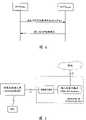
图6是本发明MS与演进分组核心网间信令连接建立的流程图,空闲状态的MS与演进分组核心网进行通信之前,需要建立MS与演进分组核心网间的信令连接,具体实现方法包括以下步骤:Fig. 6 is a flow chart of establishing the signaling connection between the MS and the evolved packet core network of the present invention. Before the MS in the idle state communicates with the evolved packet core network, it is necessary to establish a signaling connection between the MS and the evolved packet core network. The specific implementation method Include the following steps:
步骤600:MS向Evolved RAN发送AS连接请求消息。Step 600: MS sends AS connection request message to Evolved RAN.
在AS连接请求消息中携带有MS发送给演进分组核心网的NAS消息,且该AS消息被作为NAS-PDU数据。该NAS消息可以是附着请求消息、跟踪区更新(Tracking Area Update Request)消息、业务请求消息或寻呼响应消息,或其他与移动性管理或会话管理相关的信令消息等。所述NAS消息为第一条接入层连接请求消息。The NAS message sent by the MS to the evolved packet core network is carried in the AS connection request message, and the AS message is taken as NAS-PDU data. The NAS message may be an attach request message, a tracking area update (Tracking Area Update Request) message, a service request message or a paging response message, or other signaling messages related to mobility management or session management. The NAS message is the first access layer connection request message.
步骤601a~步骤601b:Evolved RAN接收到AS连接请求消息后,为MS建立通信上下文,分配并建立无线信道,之后,演进无线接入网向MS返回AS连接建立消息,在该AS连接建立消息中携带有为MS分配的无线资源和各层协议的配置参数;同时,由于AS连接请求消息中携带有NAS-PDU数据,表明演进无线接入网与演进分组核心网之间需要建立S1连接,演进无线接入网为S1连接分配连接标识,之后,演进无线接入网向演进分组核心网发送连接建立请求消息,该连接建立请求消息中携带有NSA-PDU数据和所述连接标识。Step 601a-Step 601b: After receiving the AS connection request message, the Evolved RAN establishes a communication context for the MS, allocates and establishes a wireless channel, and then, the evolved radio access network returns an AS connection establishment message to the MS. In the AS connection establishment message It carries the radio resources allocated for the MS and the configuration parameters of each layer protocol; at the same time, since the AS connection request message carries NAS-PDU data, it indicates that an S1 connection needs to be established between the evolved wireless access network and the evolved packet core network, and the evolved The radio access network allocates a connection identifier for the S1 connection, and then the evolved radio access network sends a connection establishment request message to the evolved packet core network, and the connection establishment request message carries NSA-PDU data and the connection identifier.
本步骤中,AS连接建立消息和S1接口的连接建立请求消息几乎是同时从演进无线接入网发出的,AS连接建立消息和连接建立请求消息的发出顺序,取决于演进无线接入网中相关设备的实现。In this step, the AS connection establishment message and the connection establishment request message of the S1 interface are sent from the evolved radio access network almost at the same time, and the order in which the AS connection establishment message and the connection establishment request message are sent depends on the related implementation of the device.
步骤602a~步骤602b:MS接收到AS连接建立消息后,根据该AS连接建立消息携带的信息,配置空中接口各层协议,建立并激活上行信道,之后,MS向演进无线接入网返回AS连接建立完成消息,以示AS连接建立完成;同时,演进分组核心网接收到连接建立请求消息后,存储该连接建立请求消息中携带的连接标识,为MS建立通信上下文,将NAS-PDU发送给上层协议处理,之后,向演进无线接入网返回连接建立响应消息。Step 602a-Step 602b: After receiving the AS connection establishment message, the MS configures the protocols of each layer of the air interface according to the information carried in the AS connection establishment message, establishes and activates the uplink channel, and then returns the AS connection to the evolved wireless access network. Establishment complete message to indicate that the AS connection is established; at the same time, after receiving the connection establishment request message, the evolved packet core network stores the connection identifier carried in the connection establishment request message, establishes a communication context for the MS, and sends the NAS-PDU to the upper layer After protocol processing, return a connection establishment response message to the evolved radio access network.
所述上层协议是指管理用户移动性的协议实体和管理会话的协议实体。The upper layer protocol refers to a protocol entity that manages user mobility and a protocol entity that manages sessions.
本步骤中,AS连接建立完成消息和连接建立响应消息几乎是同时到达演进无线接入网的,AS连接建立完成消息和连接建立响应消息的先后顺序取决于MS和演进分组核心网的实现和实际处理过程。In this step, the AS connection establishment complete message and the connection establishment response message arrive at the evolved wireless access network almost at the same time, and the order of the AS connection establishment complete message and the connection establishment response message depends on the implementation and actual conditions of the MS and the evolved packet core network. process.
从上述本发明方案可见,在建立MS与演进分组核心网间的信令连接的过程中,同时建立MS与演进无线接入网间的信令连接,以及演进无线接入网与演进分组核心网间的信令连接,大大缩短了MS与演进分组核心网间连接建立的时间,满足了演进网络对接入和切换时间提出的要求。It can be seen from the above scheme of the present invention that during the process of establishing the signaling connection between the MS and the evolved packet core network, the signaling connection between the MS and the evolved radio access network, and the evolved radio access network and the evolved packet core network are simultaneously established. The signaling connection between the MS and the evolved packet core network greatly shortens the time for establishing the connection between the MS and the evolved packet core network, and meets the requirements of the evolved network for access and handover time.
理论上,如果将一条消息的处理时间,比如发送、接收、消息传送的处理时间作为一个时间单位,现有技术中,参见图3,信令连接过程需要5个时间单位,而本发明中,参见图6,因为步骤601a与步骤601b是并行处理的、步骤602a与步骤602b几乎是并行处理的,因此,本发明实现移动台与演进分组核心网间连接建立过程只需要3个时间单位,比现有技术方法减少了40%的执行时间,大大缩短了MS与演进分组核心网间连接建立的时间,满足了演进网络对接入时间提出的要求。Theoretically, if the processing time of a message, such as the processing time of sending, receiving, and message transmission, is taken as a time unit, in the prior art, referring to Figure 3, the signaling connection process requires 5 time units, while in the present invention, Referring to Fig. 6, because step 601a and step 601b are processed in parallel, and step 602a and step 602b are almost processed in parallel, therefore, the present invention only needs 3 time units to realize the connection establishment process between the mobile station and the evolved packet core network. The method in the prior art reduces the execution time by 40%, greatly shortens the time for establishing a connection between the MS and the evolved packet core network, and meets the requirements of the evolved network for access time.
下面具体描述本发明演进无线接入网与演进分组核心网间信令连接建立的方法。The method for establishing a signaling connection between the evolved radio access network and the evolved packet core network of the present invention will be specifically described below.
图7是本发明演进网络中S1接口协议栈示意图一,图8是本发明演进网络中S1接口协议栈示意图二,下面对这两种S1接口协议栈进行描述。FIG. 7 is the first schematic diagram of the S1 interface protocol stack in the evolved network of the present invention, and FIG. 8 is the second schematic diagram of the S1 interface protocol stack in the evolved network of the present invention. The two S1 interface protocol stacks are described below.
如图7和图8所示,两种方案采用相同的控制面协议,无线网络层信令协议(RNL Signaling)由UDP/IP承载,RNL Signaling在本发明中用于表示无线网络层的控制面协议,具体的名称由3GPP组织定义。RNL Signaling实现与无线网络有关的信令控制,完成S1接口信令连接的建立和释放、演进无线接入网与演进分组核心网之间的信令消息交互、NAS消息的传送和用户面数据隧道的建立和释放等;As shown in Figure 7 and Figure 8, the two schemes adopt the same control plane protocol, the radio network layer signaling protocol (RNL Signaling) is carried by UDP/IP, and RNL Signaling is used to represent the control plane of the radio network layer in the present invention Protocol, the specific name is defined by the 3GPP organization. RNL Signaling realizes the signaling control related to the wireless network, completes the establishment and release of the S1 interface signaling connection, the signaling message interaction between the evolved radio access network and the evolved packet core network, the transmission of NAS messages and the user plane data tunnel establishment and release, etc.;
用户面的隧道协议有两种,一种是继续使用GTP-U隧道协议,另一种是使用通用路由封装协议(GRE,Generic Routing Encapsulation)隧道协议。其中,使用GTP-U隧道协议,有利于实现演进网络与UMTS网络之间的切换;而由于GRE隧道协议在IETF定义的Internet网络中被广泛使用,因此使用GRE隧道协议,使得S1接口更加通用。图7中,用户面的传输网络层与现有技术相同,采用GTP-U/UDP/IP协议栈。图8中,用户面的传输网络层采用GRE隧道协议,采用GRE/UDP/IP协议栈。另外,在图7和图8中,RNL UP是无线网络层的用户面协议,具体采用什么用户面协议,比如仍然采用透明模式的Iu UP,3GPP目前未定义,由于无线网络层与传输网络层的协议可以独立发展,而本发明的重点关注传输网络层的协议实现,因此,RNLUP采用何种协议,与本发明方法无关。There are two tunneling protocols on the user plane, one is to continue to use the GTP-U tunneling protocol, and the other is to use the Generic Routing Encapsulation (GRE, Generic Routing Encapsulation) tunneling protocol. Among them, the use of the GTP-U tunnel protocol is beneficial to realize the handover between the evolved network and the UMTS network; and because the GRE tunnel protocol is widely used in the Internet network defined by the IETF, the use of the GRE tunnel protocol makes the S1 interface more general. In FIG. 7 , the transmission network layer of the user plane is the same as that of the prior art, using the GTP-U/UDP/IP protocol stack. In Fig. 8, the transmission network layer of the user plane adopts the GRE tunnel protocol and the GRE/UDP/IP protocol stack. In addition, in Figure 7 and Figure 8, RNL UP is the user plane protocol of the wireless network layer. What user plane protocol is used specifically, such as Iu UP in transparent mode, is not defined by 3GPP at present, because the wireless network layer and the transport network layer The protocol of RNLUP can be developed independently, but the focus of the present invention is on the implementation of the protocol of the transport network layer. Therefore, which protocol RNLUP adopts has nothing to do with the method of the present invention.
与图2相比,图7和图8中,演进网络S1接口的控制面传输网络层由UDP代替了SCCP/M3UA/SCTP,由UDP/IP承载上层的无线网络层协议数据,简化了协议栈结构,从而降低了设备在接口上的实现复杂度、提高了S1接口的处理效率。Compared with Figure 2, in Figure 7 and Figure 8, UDP is used to replace SCCP/M3UA/SCTP at the control plane transmission network layer of the S1 interface of the evolved network, and UDP/IP carries the upper layer wireless network layer protocol data, which simplifies the protocol stack structure, thereby reducing the implementation complexity of the device on the interface and improving the processing efficiency of the S1 interface.
图7和图8所示的两种S1接口协议栈,本发明方法均支持,下面具体描述基于本发明S1接口协议栈的演进无线接入网与演进分组核心网间信令连接建立的方法,图9是本发明S1连接建立的流程图,需要说明的是,S1连接的建立可以由演进无线接入网发起,也可以由演进分组核心网发起,图9所示的是由演进无线接入网发起的S1连接建立过程。当演进无线接入网接收到来自MS的第一条NAS消息,并检查出该MS在S1接口还未建立信令连接,因此需要建立演进无线接入网与演进分组核心网间S1接口的信令连接,具体包括以下步骤:The two S1 interface protocol stacks shown in FIG. 7 and FIG. 8 are supported by the method of the present invention. The method for establishing a signaling connection between the evolved wireless access network and the evolved packet core network based on the S1 interface protocol stack of the present invention is described in detail below. Figure 9 is a flowchart of the establishment of the S1 connection in the present invention. It should be noted that the establishment of the S1 connection can be initiated by the evolved wireless access network or the evolved packet core network. The S1 connection establishment process initiated by the network. When the evolved radio access network receives the first NAS message from the MS and checks that the MS has not yet established a signaling connection on the S1 interface, it needs to establish a signaling connection between the evolved radio access network and the evolved packet core network on the S1 interface. command connection, including the following steps:
步骤900:演进无线接入网为S1连接分配唯一的连接标识,向演进分组核心网发送用于发起S1连接建立的连接建立请求消息。Step 900: The evolved radio access network allocates a unique connection identifier for the S1 connection, and sends a connection establishment request message for initiating establishment of the S1 connection to the evolved packet core network.
连接建立请求消息由下层的UDP/IP完成传送,该连接建立请求消息中至少携带以下信息:The connection establishment request message is transmitted by the lower layer UDP/IP, and the connection establishment request message carries at least the following information:
消息类型:用于标识该消息的类型为连接建立请求;Message type: used to identify the type of the message as a connection establishment request;
连接标识:用于在S1接口唯一标识一个MS的信令连接;Connection ID: used to uniquely identify a signaling connection of an MS on the S1 interface;
接入网节点标识:用于标识演进无线接入网中,与演进分组核心网互连的设备的设备标识,比如,当演进无线接入网中与演进分组核心网互连的设备只有一个E-NodeB时,接入网节点标识为该E-NodeB的ID号;Access network node identifier: used to identify the device identifier of the device interconnected with the evolved packet core network in the evolved wireless access network. For example, when the device interconnected with the evolved packet core network in the evolved wireless access network has only one E In the case of -NodeB, the access network node is identified as the ID number of the E-NodeB;
位置信息:用于标识MS当前的位置信息,该位置信息可以是跟踪区标识(TAI,Tracking Area Identity)、小区标识、服务区标识,或者上述各位置信息的任意组合,只要表示出MS的当前位置信息即可;Location information: used to identify the current location information of the MS. The location information can be Tracking Area Identity (TAI, Tracking Area Identity), cell identifier, service area identifier, or any combination of the above location information, as long as it indicates the current location of the MS location information;
NAS-PDU数据:演进无线接入网接收到的被封装成NAS-PDU数据的NAS消息。NAS-PDU data: NAS messages received by the evolved radio access network and encapsulated into NAS-PDU data.
连接建立请求消息中还可以进一步包括用户标识,该用户标识可以是永久性标识如国际移动用户标识(IMSI),或临时性标识如分组临时移动用户标识(P-TMSI)等。The connection establishment request message may further include a user identifier, which may be a permanent identifier such as an International Mobile Subscriber Identity (IMSI), or a temporary identifier such as a Packet Temporary Mobile Subscriber Identity (P-TMSI).
步骤901:演进分组核心网接收到连接建立请求消息后,为MS创建S1接口信令连接的通信上下文,存储该连接建立请求消息中携带的连接标识、接入网节点标识和位置信息,并将消息中携带的NAS-PDU数据提交给上层协议进行处理;演进分组核心网向演进无线接入网返回连接建立响应消息,在消息中携带连接建立成功的成功标识。Step 901: After receiving the connection establishment request message, the evolved packet core network creates a communication context for the S1 interface signaling connection for the MS, stores the connection identification, access network node identification and location information carried in the connection establishment request message, and sends The NAS-PDU data carried in the message is submitted to the upper-layer protocol for processing; the evolved packet core network returns a connection establishment response message to the evolved radio access network, and the message carries a success identifier of a successful connection establishment.
若演进分组核心网不能为MS建立S1接口信令连接,演进分组核心网在连接建立响应消息中携带失败原因。或者,演进分组核心网向演进无线接入网返回一表示S1接口信令连接建立失败的特殊的消息,比如连接建立拒绝消息,并在该连接建立拒绝消息中携带失败原因。If the evolved packet core network cannot establish the S1 interface signaling connection for the MS, the evolved packet core network carries the failure reason in the connection establishment response message. Alternatively, the evolved packet core network returns to the evolved radio access network a special message indicating that the signaling connection of the S1 interface fails to be established, such as a connection establishment rejection message, and the failure reason is carried in the connection establishment rejection message.
连接建立响应消息或连接建立拒绝消息中,应携带以下信息:用于标识该消息的类型为连接建立请求的响应消息的消息类型信息、以及用于携带接收到的连接标识的连接标识信息。MS在S1接口的信令连接成功建立之后,对于激活态的MS,在演进无线接入网与演进分组核心网之间交互的所有RNL Signaling消息中均携带所述的连接标识,以区分不同的MS。The connection establishment response message or the connection establishment rejection message should carry the following information: message type information used to identify the message type as a response message of a connection establishment request, and connection identification information used to carry the received connection identification. After the signaling connection of the MS on the S1 interface is successfully established, for the MS in the active state, all RNL Signaling messages exchanged between the evolved radio access network and the evolved packet core network carry the connection identifier to distinguish different MS.
所述上层协议为负责处理移动性管理功能的协议实体,或负责处理会话管理的协议实体等。The upper layer protocol is a protocol entity responsible for handling mobility management functions, or a protocol entity responsible for handling session management, and the like.
由演进分组核心网发起的S1连接建立过程与图9所示方法类似,这里不再进行描述。The process of establishing the S1 connection initiated by the evolved packet core network is similar to the method shown in FIG. 9 , and will not be described here again.
图9所示的流程是在S1接口交互与呼叫相关的信令消息时,在S1接口建立的S1连接,以实现演进无线接入网与演进分组核心网间信令连接的方法。除此之外,在S1接口交互的与呼叫无关的信令消息,以及寻呼请求消息时,不需要建立S1连接。图10是本发明通过S1接口发起寻呼的流程图,如图10所示,以寻呼请求为例,采用本发明提出的S1接口协议栈,演进分组核心网发送寻呼请求消息给演进无线接入网的方法,在演进分组核心网接收到某MS的下行数据或业务建立请求时,且此时MS处于空闲状态,那么,演进分组核心网会寻呼MS,包括:The process shown in FIG. 9 is a method for establishing an S1 connection on the S1 interface when exchanging call-related signaling messages on the S1 interface, so as to realize the signaling connection between the evolved radio access network and the evolved packet core network. In addition, when the call-independent signaling messages and paging request messages exchanged on the S1 interface, the S1 connection does not need to be established. Figure 10 is a flow chart of the present invention initiating paging through the S1 interface. As shown in Figure 10, taking the paging request as an example, using the S1 interface protocol stack proposed by the present invention, the evolved packet core network sends a paging request message to the evolved wireless In the access network method, when the evolved packet core network receives a downlink data or service establishment request from an MS, and the MS is in an idle state at this time, then the evolved packet core network will page the MS, including:
步骤1000:演进分组核心网向演进无线接入网发送寻呼请求消息,该寻呼请求消息由下层的UDP/IP完成传送,该寻呼请求消息中至少携带以下信息:Step 1000: The evolved packet core network sends a paging request message to the evolved wireless access network, the paging request message is transmitted by the lower layer UDP/IP, and the paging request message carries at least the following information:
消息类型:用于标识该消息的类型为寻呼请求;Message type: used to identify the type of the message as a paging request;
用户标识:可以是永久性标识如IMSI,或临时性标识如P-TMSI等;User ID: It can be a permanent ID such as IMSI, or a temporary ID such as P-TMSI, etc.;
寻呼原因:用于标识寻呼的原因,如语音被叫、会话被叫;Paging reason: used to identify the reason for paging, such as voice called, session called;
位置信息:用于标识演进无线接入网在哪些区域寻呼所述某MS,位置信息可以是TAI、小区标识、服务区标识,或上述各位置信息的任意组合。Location information: used to identify the areas in which the evolved radio access network pages the certain MS. The location information can be TAI, cell ID, service area ID, or any combination of the above location information.
若演进分组核心网能够获知本次寻呼要求建立什么类型的业务,那么,寻呼请求消息中还可以进一步包括业务类型。If the evolved packet core network can know what type of service is required to be established in this paging, then the paging request message may further include the service type.
演进无线接入网接收到寻呼请求消息后,在指定的区域内寻呼所述某MS。通常,演进无线接入网在寻呼信道上发送寻呼消息给该MS,演进无线接入网具体如何发送寻呼消息给该MS,不属于本发明范畴,这里不再赘述。After receiving the paging request message, the evolved radio access network pages the certain MS in the specified area. Usually, the evolved radio access network sends the paging message to the MS on the paging channel. How the evolved radio access network sends the paging message to the MS does not belong to the scope of the present invention, and will not be repeated here.
从上述本发明的S1接口协议栈,以及演进无线接入网与演进分组核心网间的互连过程描述可见,本发明进一步简化了S1接口的控制面协议栈,降低了演进无线接入网和演进分组核心网设备的S1接口设计的复杂性,提高了S1接口的处理效率,从而大大缩短了在建立MS与演进分组核心网间的信令连接的过程中,MS与演进分组核心网间连接建立的时间,满足了演进网络对接入和切换时间提出的要求;当S1接口采用在Internet网络普遍使用的GRE隧道协议时,使得S1接口更加通用,有利于实现与其他非3GPP网络如WiMax、WLAN等的切换。同时,本发明基于上述S1接口协议栈提出了S1连接建立的方法,实现了演进无线接入网与演进分组核心网间的互连。以上所述,仅为本发明的较佳实施例而已,并非用于限定本发明的保护范围,凡在本发明的精神和原则之内所做的任何修改、等同替换、改进等,均应包含在本发明的保护范围之内。From the above description of the S1 interface protocol stack of the present invention and the interconnection process between the evolved radio access network and the evolved packet core network, it can be seen that the present invention further simplifies the control plane protocol stack of the S1 interface, reducing the cost of the evolved radio access network and the evolution of the packet core network. The complexity of the design of the S1 interface of the evolved packet core network equipment improves the processing efficiency of the S1 interface, thereby greatly shortening the connection between the MS and the evolved packet core network during the process of establishing the signaling connection between the MS and the evolved packet core network. The establishment time meets the requirements of the evolution network for access and switching time; when the S1 interface adopts the GRE tunnel protocol commonly used in the Internet network, the S1 interface is more general, which is conducive to realizing the integration with other non-3GPP networks such as WiMax, Switching of WLAN, etc. At the same time, the present invention proposes a method for establishing an S1 connection based on the above-mentioned S1 interface protocol stack, and realizes the interconnection between the evolved wireless access network and the evolved packet core network. The above is only a preferred embodiment of the present invention, and is not used to limit the protection scope of the present invention. Any modification, equivalent replacement, improvement, etc. made within the spirit and principles of the present invention shall include Within the protection scope of the present invention.
Claims (17)
Priority Applications (1)
| Application Number | Priority Date | Filing Date | Title |
|---|---|---|---|
| CNA2006100080410ACN101026861A (en) | 2006-02-23 | 2006-02-23 | Method for establishing connection between mobile station and evolution packet core network |
Applications Claiming Priority (1)
| Application Number | Priority Date | Filing Date | Title |
|---|---|---|---|
| CNA2006100080410ACN101026861A (en) | 2006-02-23 | 2006-02-23 | Method for establishing connection between mobile station and evolution packet core network |
Publications (1)
| Publication Number | Publication Date |
|---|---|
| CN101026861Atrue CN101026861A (en) | 2007-08-29 |
Family
ID=38744663
Family Applications (1)
| Application Number | Title | Priority Date | Filing Date |
|---|---|---|---|
| CNA2006100080410APendingCN101026861A (en) | 2006-02-23 | 2006-02-23 | Method for establishing connection between mobile station and evolution packet core network |
Country Status (1)
| Country | Link |
|---|---|
| CN (1) | CN101026861A (en) |
Cited By (17)
| Publication number | Priority date | Publication date | Assignee | Title |
|---|---|---|---|---|
| CN102036328A (en)* | 2009-09-30 | 2011-04-27 | 中兴通讯股份有限公司 | Method and system for processing unsuccessful business preparation during S1 switching |
| CN101547142B (en)* | 2008-03-26 | 2011-09-28 | 华为技术有限公司 | Registration method and device for packet data network connection |
| CN102291820A (en)* | 2010-06-17 | 2011-12-21 | 电信科学技术研究院 | Paging method, system and device |
| CN102595649A (en)* | 2007-11-05 | 2012-07-18 | 上海华为技术有限公司 | Mobile station proxy, base station sub-system and network adaptation method |
| CN102625998A (en)* | 2009-07-06 | 2012-08-01 | 岩星比德科有限公司 | Media Access Control for Wireless Systems |
| US8270371B2 (en) | 2007-08-13 | 2012-09-18 | Huawei Technologies Co., Ltd. | Method and apparatus for non-access stratum message processing during handover in evolved network |
| CN101541093B (en)* | 2008-03-21 | 2013-04-24 | 华为技术有限公司 | Method and device for establishing and maintaining interface connection |
| CN103875267A (en)* | 2013-12-24 | 2014-06-18 | 华为技术有限公司 | Access node, mobile management network element and paging message processing method |
| CN101998369B (en)* | 2009-08-18 | 2015-03-25 | 中兴通讯股份有限公司 | Transmission method and system of uplink message |
| CN104581791A (en)* | 2008-01-31 | 2015-04-29 | 日本电气株式会社 | Wireless communication system, base station device, move control node, and method of wireless communication |
| WO2017193965A1 (en)* | 2016-05-13 | 2017-11-16 | Huawei Technologies Co., Ltd. | Systems and methods for network slice attachment and configuration |
| CN108029060A (en)* | 2015-10-09 | 2018-05-11 | 英特尔Ip公司 | Network initiated packet data network connection |
| CN108353282A (en)* | 2015-11-17 | 2018-07-31 | 高通股份有限公司 | Method and apparatus for the wireless communication for using the security model for supporting multiple connectivities and service context |
| WO2018137152A1 (en)* | 2017-01-24 | 2018-08-02 | 华为技术有限公司 | Short message transmission method, device and system |
| CN108616956A (en)* | 2017-01-16 | 2018-10-02 | 普天信息技术有限公司 | A kind of method that business is isolated in electric power wireless private network |
| CN108616995A (en)* | 2016-12-30 | 2018-10-02 | 中国电信股份有限公司 | Mobile network service adaptation method, equipment, terminal, base station and mobile communication system |
| WO2019183885A1 (en)* | 2018-03-29 | 2019-10-03 | Oppo广东移动通信有限公司 | Method for handover between network elements, and user equipment, network element and computer storage medium |
- 2006
- 2006-02-23CNCNA2006100080410Apatent/CN101026861A/enactivePending
Cited By (46)
| Publication number | Priority date | Publication date | Assignee | Title |
|---|---|---|---|---|
| US8665820B2 (en) | 2007-08-13 | 2014-03-04 | Huawei Technologies Co., Ltd. | Method and apparatus for non-access stratum message processing during handover in evolved network |
| US11399323B2 (en) | 2007-08-13 | 2022-07-26 | Huawei Technologies Co., Ltd. | Method and apparatus for non-access stratum message processing during handover in evolved network |
| US10750409B2 (en) | 2007-08-13 | 2020-08-18 | Huawei Technologies Co., Ltd. | Method and apparatus for non-access stratum message processing during handover in evolved network |
| US10075880B2 (en) | 2007-08-13 | 2018-09-11 | Huawei Technologies Co., Ltd. | Method and apparatus for non-access stratum message processing during handover in evolved network |
| US9215624B2 (en) | 2007-08-13 | 2015-12-15 | Huawei Technologies Co., Ltd. | Method and apparatus for non-access stratum message processing during handover in evolved network |
| US8270371B2 (en) | 2007-08-13 | 2012-09-18 | Huawei Technologies Co., Ltd. | Method and apparatus for non-access stratum message processing during handover in evolved network |
| CN102595649B (en)* | 2007-11-05 | 2015-04-08 | 上海华为技术有限公司 | Mobile station proxy, base station sub-system and network adaptation method |
| CN102595649A (en)* | 2007-11-05 | 2012-07-18 | 上海华为技术有限公司 | Mobile station proxy, base station sub-system and network adaptation method |
| US10271230B2 (en) | 2008-01-31 | 2019-04-23 | Nec Corporation | Wireless communication system, base station device, move control node, and method of wireless communication |
| US10791473B2 (en) | 2008-01-31 | 2020-09-29 | Nec Corporation | Wireless communication system, base station device, move control node, and method of wireless communication |
| US10492087B2 (en) | 2008-01-31 | 2019-11-26 | Nec Corporation | Wireless communication system, base station device, move control node, and method of wireless communication |
| US20180199216A1 (en) | 2008-01-31 | 2018-07-12 | Nec Corporation | Wireless communication system, base station device, move control node, and method of wireless communication |
| CN104581791A (en)* | 2008-01-31 | 2015-04-29 | 日本电气株式会社 | Wireless communication system, base station device, move control node, and method of wireless communication |
| US9949150B2 (en) | 2008-01-31 | 2018-04-17 | Nec Corporation | Wireless communication system, base station device, move control node, and method of wireless communication |
| CN101541093B (en)* | 2008-03-21 | 2013-04-24 | 华为技术有限公司 | Method and device for establishing and maintaining interface connection |
| CN101547142B (en)* | 2008-03-26 | 2011-09-28 | 华为技术有限公司 | Registration method and device for packet data network connection |
| CN102625998A (en)* | 2009-07-06 | 2012-08-01 | 岩星比德科有限公司 | Media Access Control for Wireless Systems |
| CN102625998B (en)* | 2009-07-06 | 2015-12-09 | 苹果公司 | Media Access Control for Wireless Systems |
| CN101998369B (en)* | 2009-08-18 | 2015-03-25 | 中兴通讯股份有限公司 | Transmission method and system of uplink message |
| CN102036328A (en)* | 2009-09-30 | 2011-04-27 | 中兴通讯股份有限公司 | Method and system for processing unsuccessful business preparation during S1 switching |
| CN102291820A (en)* | 2010-06-17 | 2011-12-21 | 电信科学技术研究院 | Paging method, system and device |
| CN102291820B (en)* | 2010-06-17 | 2015-04-01 | 电信科学技术研究院 | Paging method, system and device |
| CN103875267B (en)* | 2013-12-24 | 2017-09-08 | 华为技术有限公司 | Access node, mobile management net element and processing method for paging message |
| US10321355B2 (en) | 2013-12-24 | 2019-06-11 | Huawei Technologies Co., Ltd. | Access node, mobility management network element, and paging message processing method |
| CN103875267A (en)* | 2013-12-24 | 2014-06-18 | 华为技术有限公司 | Access node, mobile management network element and paging message processing method |
| US11930413B2 (en) | 2015-10-09 | 2024-03-12 | Apple Inc. | Network initiated connection transfer |
| US11405836B2 (en) | 2015-10-09 | 2022-08-02 | Apple Inc. | Network initiated connection transfer |
| US12335803B2 (en) | 2015-10-09 | 2025-06-17 | Apple Inc. | Network-initiated connection transfer |
| CN108029060A (en)* | 2015-10-09 | 2018-05-11 | 英特尔Ip公司 | Network initiated packet data network connection |
| US11729619B2 (en) | 2015-11-17 | 2023-08-15 | Qualcomm Incorporated | Methods and apparatus for wireless communication using a security model to support multiple connectivity and service contexts |
| CN108353282B (en)* | 2015-11-17 | 2021-11-19 | 高通股份有限公司 | Method and apparatus for wireless communication using a security model supporting multiple connectivity and service contexts |
| CN108353282A (en)* | 2015-11-17 | 2018-07-31 | 高通股份有限公司 | Method and apparatus for the wireless communication for using the security model for supporting multiple connectivities and service context |
| US11234126B2 (en) | 2015-11-17 | 2022-01-25 | Qualcomm Incorporated | Methods and apparatus for wireless communication using a security model to support multiple connectivity and service contexts |
| WO2017193965A1 (en)* | 2016-05-13 | 2017-11-16 | Huawei Technologies Co., Ltd. | Systems and methods for network slice attachment and configuration |
| US11026060B2 (en) | 2016-05-13 | 2021-06-01 | Huawei Technologies Co., Ltd. | Systems and methods for network slice attachment and configuration |
| CN110445661B (en)* | 2016-05-13 | 2020-11-10 | 华为技术有限公司 | System and method for network slice attachment and configuration |
| CN110445661A (en)* | 2016-05-13 | 2019-11-12 | 华为技术有限公司 | Systems and methods for network slice attachment and configuration |
| US12133146B2 (en) | 2016-05-13 | 2024-10-29 | Huawei Technologies Co., Ltd. | Systems and methods for network slice attachment and configuration |
| CN108616995B (en)* | 2016-12-30 | 2021-07-30 | 中国电信股份有限公司 | Mobile network service adaptation method, equipment, terminal, base station and mobile communication system |
| CN108616995A (en)* | 2016-12-30 | 2018-10-02 | 中国电信股份有限公司 | Mobile network service adaptation method, equipment, terminal, base station and mobile communication system |
| CN108616956B (en)* | 2017-01-16 | 2020-10-20 | 普天信息技术有限公司 | Method for service isolation in electric power wireless private network |
| CN108616956A (en)* | 2017-01-16 | 2018-10-02 | 普天信息技术有限公司 | A kind of method that business is isolated in electric power wireless private network |
| US11012825B2 (en) | 2017-01-24 | 2021-05-18 | Huawei Technologies Co., Ltd. | Short message transmission method, device, and system |
| WO2018137152A1 (en)* | 2017-01-24 | 2018-08-02 | 华为技术有限公司 | Short message transmission method, device and system |
| WO2019183885A1 (en)* | 2018-03-29 | 2019-10-03 | Oppo广东移动通信有限公司 | Method for handover between network elements, and user equipment, network element and computer storage medium |
| US11490308B2 (en) | 2018-03-29 | 2022-11-01 | Guangdong Oppo Mobile Telecommunications Corp., Ltd. | Method for switching between network elements and network element selection, user equipment, network element |
Similar Documents
| Publication | Publication Date | Title |
|---|---|---|
| CN101026861A (en) | Method for establishing connection between mobile station and evolution packet core network | |
| JP4230106B2 (en) | Selection of multiple Internet service providers by GPRS subscribers | |
| JP5270657B2 (en) | Mobility management (MM) and session management (SM) for SAE / LTE | |
| EP2797380B1 (en) | Method, entity and system for realizing cluster service | |
| US7042855B1 (en) | Method for routing data in a communication system | |
| CN101115292B (en) | Method for paging and connecting terminal and terminal and system for fast activating data transmission | |
| JP4412604B2 (en) | Method and apparatus for supporting interconnection between wireless LAN and mobile communication system | |
| JP3830898B2 (en) | Method and network system for providing packet voice call service in a wireless communication network | |
| CN101009907B (en) | Establishment and release method of the tunnel in the evolution network framework and its device | |
| CN101039507B (en) | Method and apparatus for establishing and releasing tunnel in evolution network framework | |
| JP4982545B2 (en) | PDCP structure and operation method for MBMS service of mobile communication system | |
| CN100428708C (en) | Method for establishing a communication channel in an internet protocol mobile network | |
| US20070213058A1 (en) | Method and apparatus for supporting handoff and serving radio network subsystem relocation procedures in a single tunnel gprs-based wireless communication system | |
| US20100150049A1 (en) | bearer control and management method in the ip-based evolved mobile communication network | |
| WO2008025243A1 (en) | An access gateway, enb and method of the evolved multimedia broadcast multicast service | |
| EP2536184A1 (en) | Method, device and system for reporting wireless access network element information | |
| CN112911726A (en) | Method and device for establishing user plane bearer | |
| WO2009100628A1 (en) | Method, system and device for connection establishment based on lte/sae system | |
| CN101365159B (en) | Bearing identification processing method and apparatus | |
| CN101588570B (en) | Method and system for establishing single tunnel of user plane and base station subsystem thereof | |
| US7492709B2 (en) | Data transmission method and network elements | |
| CN102394818A (en) | PS domain system for small-sized mobile core network and message processing method | |
| CN100484290C (en) | Method for realizing PDP address distribution in service cut-in | |
| KR101041675B1 (en) | Method and system for transmitting user data over dialed connection in wireless communication network | |
| CN101442715B (en) | Method, apparatus and system implementing GPRS network flat architecture |
Legal Events
| Date | Code | Title | Description |
|---|---|---|---|
| C06 | Publication | ||
| PB01 | Publication | ||
| C02 | Deemed withdrawal of patent application after publication (patent law 2001) | ||
| WD01 | Invention patent application deemed withdrawn after publication |