CN101013136B - Laser-induction fluorescence co-focusing scanning device and method - Google Patents
Laser-induction fluorescence co-focusing scanning device and methodDownload PDFInfo
- Publication number
- CN101013136B CN101013136BCN2007100637132ACN200710063713ACN101013136BCN 101013136 BCN101013136 BCN 101013136BCN 2007100637132 ACN2007100637132 ACN 2007100637132ACN 200710063713 ACN200710063713 ACN 200710063713ACN 101013136 BCN101013136 BCN 101013136B
- Authority
- CN
- China
- Prior art keywords
- lens
- biochip
- laser
- fluorescence
- computer
- Prior art date
- Legal status (The legal status is an assumption and is not a legal conclusion. Google has not performed a legal analysis and makes no representation as to the accuracy of the status listed.)
- Expired - Fee Related
Links
Images


Landscapes
- Investigating, Analyzing Materials By Fluorescence Or Luminescence (AREA)
Abstract
Translated fromChinese
Description
Translated fromChinese技术领域technical field
本发明一种激光诱导荧光共聚焦扫描装置,激光诱导荧光共聚焦扫描装置和方法属于生物芯片检测技术领域。The invention discloses a laser-induced fluorescence confocal scanning device, and the laser-induced fluorescence confocal scanning device and method belong to the technical field of biochip detection.
背景技术Background technique
生物芯片作为一种新兴高科技产品正在被广泛应用于生命科学、医学研究和应用,生物芯片的概念源自于计算机芯片。狭义的生物芯片是指包被在固相载体如硅片、玻璃、塑料和尼龙膜等上的高密度DNA、蛋白质、细胞等生物活性物质的微阵列,主要包括cDNA微阵列、寡核苷酸微阵列和蛋白质微阵列。这些微阵列是由生物活性物质以点阵的形式有序地固定在固相载体上形成的。在一定的条件下进行生化反应,反应结果用化学荧光法、酶标法、同位素法显示,再用扫描仪等光学仪器进行数据采集,最后通过专门的计算机软件进行数据分析。对于广义生物芯片而言,除了上述被动式微阵列芯片之外,还包括利用光刻技术和微加工技术在固体基片表面构建微流体分析单元和系统以实现对生物分子进行快速、大信息量并行处理和分析的微型固体薄型器件。包括核酸扩增芯片、阵列毛细管电泳芯片、主动式电磁生物芯片等。As a new high-tech product, biochips are being widely used in life sciences, medical research and applications. The concept of biochips is derived from computer chips. In a narrow sense, biochips refer to microarrays of high-density DNA, proteins, cells and other biologically active substances coated on solid carriers such as silicon wafers, glass, plastics, and nylon membranes, mainly including cDNA microarrays, oligonucleotides, etc. Microarrays and protein microarrays. These microarrays are formed by orderly immobilizing biologically active substances on solid phase supports in the form of lattices. The biochemical reaction is carried out under certain conditions, and the reaction results are displayed by chemical fluorescence method, enzyme label method, and isotope method, and then the data is collected by optical instruments such as scanners, and finally the data is analyzed by special computer software. For generalized biochips, in addition to the above-mentioned passive microarray chips, it also includes the use of photolithography and micromachining techniques to build microfluidic analysis units and systems on the surface of solid substrates to achieve fast and large-information parallel biomolecules. Miniature solid thin devices for processing and analysis. Including nucleic acid amplification chips, array capillary electrophoresis chips, active electromagnetic biochips, etc.
生物芯片检测方面主要的技术手段有共聚焦扫描法和基于CCD(Charge-coupled device)的检测法。由于共聚焦扫描法具有灵敏度高的特点,大多数的微阵列生物芯片扫描仪采用的都是共聚焦扫描原理的。The main technical means of biochip detection are confocal scanning method and detection method based on CCD (Charge-coupled device). Due to the high sensitivity of the confocal scanning method, most microarray biochip scanners use the confocal scanning principle.
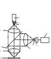
经典的基于激光共聚焦扫描的生物芯片检测装置一般利用半反半透镜对入射的激光和诱导出来的荧光进行分光,如图1所示。激光器1发出的激光经过第一透镜2和第一针孔3后成为点光源,经过第二透镜4准直,准直光经过一个半反半透镜6后,再经过第三透镜8汇聚到其后焦面上,诱导该透镜焦面上生物芯片10发出荧光,荧光经过第三透镜8后准直,投射到半反半透镜6上,半反半透镜6将投射其上的荧光反射到第四透镜12上,第四透镜12将反射其上的荧光汇聚到第四透镜12的后焦点,该焦点上放置一个针孔13,紧临针孔放置一个光电探测器14,光电探测器将接收的荧光信号转化为数字化电信号后送入计算机15。为了得到能量集中信噪比好的荧光信号,必须调焦,经典的调焦是利用成像目镜观察光斑的是否清晰成像,手动调焦。The classic biochip detection device based on laser confocal scanning generally uses a half mirror to split the incident laser light and the induced fluorescence, as shown in Figure 1. The laser light emitted by the
上述装置中利用半反半透镜将激光和激光诱导出来的荧光进行分光,荧光的收集和利用效率不高,入射的激光在分光时大约有50%的能量损失,同时透镜收集到的荧光也有大约有50%的能量损失。如果是多路不同波长的激光,诱导不同波长的荧光,荧光收集和利用效率将更低;同时光源的针孔和探测器的针孔严格保持共聚焦关系,扫描过程中的调焦控制非常困难。In the above-mentioned device, a semi-reflective lens is used to split the laser and the fluorescence induced by the laser. The collection and utilization efficiency of the fluorescence is not high. The incident laser has about 50% energy loss when splitting the light, and the fluorescence collected by the lens also has about 50% energy loss. There is a 50% energy loss. If there are multiple lasers with different wavelengths, different wavelengths of fluorescence will be induced, and the efficiency of fluorescence collection and utilization will be lower; at the same time, the pinhole of the light source and the pinhole of the detector maintain a strict confocal relationship, and it is very difficult to control the focus during scanning. .
发明内容Contents of the invention
本发明的目的在于提供一种生物芯片检测装置,目的之一就是改进荧光检测的光路,利用中间打孔的全反透镜作为分光器件提高荧光收集效率。目的之二为共聚焦而提出的改变,控制扫描时生物芯片在焦平面及其上下焦深范围,通过扫描前沿着生物芯片的矩形两个对角线预扫描的方式,调节镜头的位置使整个生物芯片的有效部分在预扫描过程中落在镜头的焦平面及其上下焦深范围内。The object of the present invention is to provide a biological chip detection device, one of the objects is to improve the optical path of fluorescence detection, and to improve the efficiency of fluorescence collection by using the total reflection lens with a hole in the middle as a spectroscopic device. The second purpose is to change the confocal, control the biochip on the focal plane and its upper and lower focal depth range during scanning, and adjust the position of the lens by pre-scanning along the two diagonals of the biochip rectangle before scanning to make the whole The effective part of the biochip falls within the focal plane of the lens and its upper and lower focal depth ranges during the pre-scanning process.
一种基于激光诱导荧光共聚焦扫描装置的扫描生物芯片的方法,包括以下步骤:A method for scanning a biochip based on a laser-induced fluorescence confocal scanning device, comprising the following steps:
1)打开激光器1预热;1) Turn on
2)激光器1发出的激光经过由第一透镜2、第一针孔3、第二透镜4组成的扩束系统扩束成直径为1毫米的光束5,该光束5从中间打孔的全反射镜7的透光孔中通过,垂直照射到的第三透镜8上,该第三透镜8将激光汇聚到后焦面处的生物芯片10上,汇聚到生物芯片10上的部分激光透过生物芯片10,经过反射镜16的反射,被基于四象限光电探测器的探测系统得到,进入计算机15进行调焦,保证扫描过程中生物芯片10始终在透镜8焦点上以及焦深范围内,这样第二针孔13与第一针孔3始终近似地成共聚焦关系。因此必须利用调焦装置9对生物芯片调焦,调焦过程为:部分垂直入射的激光从生物芯片10透射,经过调焦光学系统,即透镜17和柱面镜18后,成像于四象限光电探测器19,适当选择透镜和柱面镜的参数,可以得到一定的调焦范围和一定的调焦精度。四象限光电探测器19接受的光信号转化为电信号,经过滤波与放大处理,传输到计算机15里,经过计算产生差动信号与预先设定值比较,产生驱动信号驱动电机由电机带动与驱动电机相连的机械传动装置运动,透镜8与机械传动装置一起沿着光轴线方向上下平动,直到物镜到达要求的目标焦平面位置。对生物芯片对角线扫描,逐点调焦,使得整个生物芯片10在透镜8的焦深范围。2) The laser light emitted by the
3)汇聚到生物芯片10上的另一部分激光诱导生物芯片10上的生物样品上某一斑点发出荧光11,发出的荧光的一部分经过第三透镜8,变成准直光投射到全反射镜7上反射,传播到的第四透镜12上,会聚到第四透镜12的后焦平面的针孔13上,光电探测器14接收荧光,将该点的荧光信号转化电信号,数字化进入计算机15;3) Another part of the laser beam converged on the
4)移动生物芯片10,使透镜8汇聚的激光斑点逐点二维扫描整个生物芯片10。4) Moving the
本发明的优点在于:The advantages of the present invention are:
1.采用中间打孔的全反射镜对入射的激光和诱导反射的荧光进行分光,激光束经过孔径时,能量损失小,几乎全部激光能量可以照射到生物芯片上,并且在收集荧光时,荧光收集角度大,效率高不但提高激光入射效率而且提高了荧光的收集效率,可以达到80—90%。1. A total reflection mirror with a hole in the middle is used to split the incident laser light and the induced reflection fluorescence. When the laser beam passes through the aperture, the energy loss is small, and almost all the laser energy can be irradiated on the biochip, and when the fluorescence is collected, the fluorescence The collection angle is large and the efficiency is high, which not only improves the incident efficiency of laser light but also improves the collection efficiency of fluorescence, which can reach 80-90%.
2.利用计算机控制,使光源的针孔和探测器的针孔保持近似共聚焦关系,只需要扫描前调焦一次,调焦控制简单方便。2. Using computer control, the pinhole of the light source and the pinhole of the detector maintain an approximate confocal relationship, and only need to adjust the focus once before scanning, and the focus control is simple and convenient.
附图说明Description of drawings
图1经典的单路入射光的共聚焦扫描生物芯片检测装置的结构示意图;Fig. 1 is a schematic structural diagram of a classic single-path confocal scanning biochip detection device;
图2为本发明的共聚焦扫描生物芯片检测装置的示意图;2 is a schematic diagram of a confocal scanning biochip detection device of the present invention;
图3为本发明的实施例中的生物芯片示意图Fig. 3 is the biochip schematic diagram in the embodiment of the present invention
图4本发明的实施例扫描方式。Fig. 4 is the scanning mode of the embodiment of the present invention.
具体实施方式:Detailed ways:
下面结合附图,详细对本发明进行说明。The present invention will be described in detail below in conjunction with the accompanying drawings.
实施例:Example:
激光器1发出的激光经过由第一透镜2、第一针孔3、第二透镜4组成的扩束系统扩束成直径为1毫米的光束5,该光束从中间所打孔孔径略大于1毫米的全反射镜7的透光孔经过,垂直照射到的第三透镜8上,该第三透镜8将激光汇聚到后焦面处的生物芯片10上。The laser light emitted by the
一部分激光汇聚到生物芯片10上并且透过生物芯片,经过反射镜16的反射,被基于四象限光电探测器的探测系统得到,进入计算机15进行调焦,保证扫描过程中生物芯片10始终在透镜8焦点上以及焦深范围内,这样第二针孔13与第一针孔3始终近似地成共聚焦关系。利用调焦装置9对生物芯片调焦,在图2所示的光学系统和图3所示的调焦装置中,调焦过程为:部分垂直入射的激光从生物芯片10透射,经过调焦光学系统,即透镜17和柱面镜18后,成像于四象限光电探测器19,适当选择透镜和柱面镜的参数,可以得到一定的调焦范围和一定的调焦精度。四象限光电探测器19接受的光信号转化为电信号,经过滤波与放大处理,传输到计算机15里,经过计算产生差动信号与预先设定值比较,产生驱动信号驱动电机,由电机带动与驱动电机相连的机械传动装置运动,透镜8与机械传动装置一起沿着光轴线方向上下平动,直到物镜到达要求的目标焦平面位置。对生物芯片对角线扫描,逐点调焦,使得整个生物芯片10在透镜8的焦深范围,否则放弃该生物芯片认为不合格,完成调焦。A part of the laser light converges on the
另一部分激光汇聚到生物芯片10上的诱导生物芯片10上的生物样品,发出荧光,一部分荧光11经过第三透镜8,变成准直光投射到全反射镜7上反射,传播到的第四透镜12上,会聚到第四透镜12的后焦平面的针孔13上,光电探测器14紧邻针孔14接收荧光,将荧光信号转化电信号,数字化进入计算机15。这样就探测得到生物芯片上的一个点的荧光光强,通过控制由直线电机和步进电机及其所带动的二维平台移动生物芯片,这里没有画出来,二维扫描得到整个生物芯片上二维点阵的荧光光强,荧光强度与生物芯片上生化反应物的数量成正比关系,根据荧光强度可以计算生物芯片上生化反应物的数量,生物芯片见图3,在75毫米×25毫米的载玻片上60毫米×20的范围内间隔150纳米点样,点样的直径150纳米左右,二维扫描的方式见图4;图4中沿着短轴方向即25毫米方向运动,同时沿着长轴75毫米运动,循环进行,扫描整个生物芯片。The other part of the laser light is focused on the
流程:开始,打开激光器1预热10分钟;检测基于四象限光电探测器系统17的探测值,通过机电装置9调整透镜8,使生物芯片10上表面处于透镜8的后焦面,并且在扫描过程中始终处于焦深范围内;同步扫描生物芯片与荧光探测,即数据采集;计算机15数据处理与显示。Process: start, turn on the
Claims (1)
Translated fromChinesePriority Applications (1)
| Application Number | Priority Date | Filing Date | Title |
|---|---|---|---|
| CN2007100637132ACN101013136B (en) | 2007-02-08 | 2007-02-08 | Laser-induction fluorescence co-focusing scanning device and method |
Applications Claiming Priority (1)
| Application Number | Priority Date | Filing Date | Title |
|---|---|---|---|
| CN2007100637132ACN101013136B (en) | 2007-02-08 | 2007-02-08 | Laser-induction fluorescence co-focusing scanning device and method |
Publications (2)
| Publication Number | Publication Date |
|---|---|
| CN101013136A CN101013136A (en) | 2007-08-08 |
| CN101013136Btrue CN101013136B (en) | 2011-07-20 |
Family
ID=38700781
Family Applications (1)
| Application Number | Title | Priority Date | Filing Date |
|---|---|---|---|
| CN2007100637132AExpired - Fee RelatedCN101013136B (en) | 2007-02-08 | 2007-02-08 | Laser-induction fluorescence co-focusing scanning device and method |
Country Status (1)
| Country | Link |
|---|---|
| CN (1) | CN101013136B (en) |
Cited By (1)
| Publication number | Priority date | Publication date | Assignee | Title |
|---|---|---|---|---|
| CN103782157A (en)* | 2011-08-30 | 2014-05-07 | 奥林巴斯株式会社 | Method for detecting target particles in biosample containing pancreatic juice |
Families Citing this family (12)
| Publication number | Priority date | Publication date | Assignee | Title |
|---|---|---|---|---|
| CN101158644B (en)* | 2007-11-16 | 2010-06-09 | 北京工业大学 | Method of Inducing Fluorescence in Rotary Multi-channel Based on Transmission Fiber |
| CN101158645B (en)* | 2007-11-16 | 2010-06-09 | 北京工业大学 | Rotary Multi-channel Excitation Fluorescence Method Based on Input-Output Optical Fiber |
| KR101513602B1 (en) | 2009-02-11 | 2015-04-22 | 삼성전자주식회사 | Bio-chip scanning method |
| CN102621117B (en)* | 2012-03-09 | 2014-03-12 | 福建师范大学 | Living cell laser scanning co-focusing microscope imaging system |
| CN104685456A (en)* | 2012-07-12 | 2015-06-03 | 伊雷克托科学工业股份有限公司 | Interactive control system, manufacturing method thereof, and device incorporating interactive control system |
| CN103063640B (en)* | 2012-12-28 | 2015-09-09 | 西北核技术研究所 | A kind of laser-induced fluorescence (LIF) combustion field parameter measuring apparatus |
| CN104967759B (en)* | 2015-02-13 | 2016-05-04 | 华中科技大学 | A kind of scanning imaging system for low light level signal |
| CN104730046A (en)* | 2015-03-20 | 2015-06-24 | 杭州电子科技大学 | Laser-induced breakdown trace amount substance analysis device |
| CN106198463A (en)* | 2015-04-30 | 2016-12-07 | 中国科学院苏州纳米技术与纳米仿生研究所 | Spectrum scan test device and method of testing thereof |
| CN105115944B (en)* | 2015-09-07 | 2017-12-29 | 北京科技大学 | A kind of auto focusing method and system for LIBS material composition detections |
| CN110779873A (en)* | 2019-10-10 | 2020-02-11 | 成都贝瑞光电科技股份有限公司 | Laser optical detection system |
| CN114994892A (en)* | 2022-05-09 | 2022-09-02 | 中国科学院化学研究所 | Laser confocal microscopy imaging system and method |
Citations (4)
| Publication number | Priority date | Publication date | Assignee | Title |
|---|---|---|---|---|
| CN1376907A (en)* | 2001-03-23 | 2002-10-30 | 成都中科百奥科技有限公司 | Laser confocusing scanner for biochip |
| CN1176367C (en)* | 2002-01-11 | 2004-11-17 | 清华大学 | Automatic focusing device of laser confocal scanner |
| DE102004013521A1 (en)* | 2004-03-19 | 2005-10-13 | Bundesrepublik Deutschland, vertr. d. d. Bundesministerium für Wirtschaft und Arbeit, dieses vertr. d. d. Präsidenten der Physikalisch-Technischen Bundesanstalt | Curved profile measuring machine has contactless probe using common ray path and confocal imaging system with suitable coated beam splitter |
| CN201014990Y (en)* | 2007-02-08 | 2008-01-30 | 北京工业大学 | Laser Induced Fluorescence Confocal Scanning Device |
- 2007
- 2007-02-08CNCN2007100637132Apatent/CN101013136B/ennot_activeExpired - Fee Related
Patent Citations (4)
| Publication number | Priority date | Publication date | Assignee | Title |
|---|---|---|---|---|
| CN1376907A (en)* | 2001-03-23 | 2002-10-30 | 成都中科百奥科技有限公司 | Laser confocusing scanner for biochip |
| CN1176367C (en)* | 2002-01-11 | 2004-11-17 | 清华大学 | Automatic focusing device of laser confocal scanner |
| DE102004013521A1 (en)* | 2004-03-19 | 2005-10-13 | Bundesrepublik Deutschland, vertr. d. d. Bundesministerium für Wirtschaft und Arbeit, dieses vertr. d. d. Präsidenten der Physikalisch-Technischen Bundesanstalt | Curved profile measuring machine has contactless probe using common ray path and confocal imaging system with suitable coated beam splitter |
| CN201014990Y (en)* | 2007-02-08 | 2008-01-30 | 北京工业大学 | Laser Induced Fluorescence Confocal Scanning Device |
Cited By (2)
| Publication number | Priority date | Publication date | Assignee | Title |
|---|---|---|---|---|
| CN103782157A (en)* | 2011-08-30 | 2014-05-07 | 奥林巴斯株式会社 | Method for detecting target particles in biosample containing pancreatic juice |
| CN103782157B (en)* | 2011-08-30 | 2016-01-20 | 奥林巴斯株式会社 | Method for detecting target particles in biological sample containing pancreatic juice |
Also Published As
| Publication number | Publication date |
|---|---|
| CN101013136A (en) | 2007-08-08 |
Similar Documents
| Publication | Publication Date | Title |
|---|---|---|
| CN101013136B (en) | Laser-induction fluorescence co-focusing scanning device and method | |
| CN102077080B (en) | Microarray characterization system and method | |
| US6597000B2 (en) | Systems and methods for detection of labeled materials | |
| JP5759377B2 (en) | Detection system and method | |
| JP6513802B2 (en) | Laser light coupling for nanoparticle detection | |
| JP2023541449A (en) | Methods and systems for multidimensional imaging | |
| JP5775693B2 (en) | Optical illumination apparatus and method | |
| WO2004001402A1 (en) | Biomolecule analyzer | |
| CN101203790A (en) | Optical system of a microarray chip laser scanner | |
| US20210010920A1 (en) | Spectroscopic analysis device, spectroscopic analysis method, program, recording medium, and microscope | |
| WO2022120047A1 (en) | Universal multi-detection system for microplates with confocal imaging | |
| CN101324527A (en) | Total reflection laser-induced fluorescence confocal scanning device and method | |
| CN201014990Y (en) | Laser Induced Fluorescence Confocal Scanning Device | |
| US20030232427A1 (en) | Optically active substrates for examination of biological materials | |
| US6670198B2 (en) | Test piece and system for reading out image information from the test piece | |
| US7173701B2 (en) | CCD-based biochip reader | |
| JP2004144839A (en) | Optical scanning device | |
| JP2004361087A (en) | Biomolecule analyzer | |
| EP2225548B1 (en) | Detection system and method | |
| JP2004354345A (en) | Biomolecule analysis apparatus | |
| CN201229304Y (en) | Perfect reflection type laser inducing fluorescent co-focusing scanner device | |
| JP2005006553A (en) | Apparatus for cell culture detection | |
| EP2163885A1 (en) | Microarray characterization system and method | |
| JP4544893B2 (en) | Optical apparatus and image creation method | |
| KR102609881B1 (en) | Apparatus for measuring two dimensional fluorescence data using one dimensional optical sensor |
Legal Events
| Date | Code | Title | Description |
|---|---|---|---|
| C06 | Publication | ||
| PB01 | Publication | ||
| C10 | Entry into substantive examination | ||
| SE01 | Entry into force of request for substantive examination | ||
| C14 | Grant of patent or utility model | ||
| GR01 | Patent grant | ||
| C17 | Cessation of patent right | ||
| CF01 | Termination of patent right due to non-payment of annual fee | Granted publication date:20110720 Termination date:20120208 |