CN101006489A - Projection apparatus comprising a led control system with feedback, and driving method therefor - Google Patents
Projection apparatus comprising a led control system with feedback, and driving method thereforDownload PDFInfo
- Publication number
- CN101006489A CN101006489ACNA2005800231575ACN200580023157ACN101006489ACN 101006489 ACN101006489 ACN 101006489ACN A2005800231575 ACNA2005800231575 ACN A2005800231575ACN 200580023157 ACN200580023157 ACN 200580023157ACN 101006489 ACN101006489 ACN 101006489A
- Authority
- CN
- China
- Prior art keywords
- light
- projection arrangement
- emitting device
- power supply
- arrangement according
- Prior art date
- Legal status (The legal status is an assumption and is not a legal conclusion. Google has not performed a legal analysis and makes no representation as to the accuracy of the status listed.)
- Granted
Links
- 238000000034methodMethods0.000titleclaimsabstractdescription23
- 230000003287optical effectEffects0.000claimsdescription19
- 238000005259measurementMethods0.000claimsdescription13
- 238000012544monitoring processMethods0.000claimsdescription6
- 239000004973liquid crystal related substanceSubstances0.000claimsdescription4
- 239000003086colorantSubstances0.000claimsdescription2
- 230000000052comparative effectEffects0.000claims1
- 238000003306harvestingMethods0.000claims1
- 230000011514reflexEffects0.000claims1
- 238000005070samplingMethods0.000description9
- 238000005286illuminationMethods0.000description6
- 238000004458analytical methodMethods0.000description5
- 238000010586diagramMethods0.000description2
- 238000004519manufacturing processMethods0.000description2
- 238000012545processingMethods0.000description2
- 239000011358absorbing materialSubstances0.000description1
- 238000012937correctionMethods0.000description1
- 230000001419dependent effectEffects0.000description1
- 239000000463materialSubstances0.000description1
- 238000012986modificationMethods0.000description1
- 230000004048modificationEffects0.000description1
- 230000000737periodic effectEffects0.000description1
- 239000004065semiconductorSubstances0.000description1
- 239000007787solidSubstances0.000description1
Images


Classifications
- G—PHYSICS
- G03—PHOTOGRAPHY; CINEMATOGRAPHY; ANALOGOUS TECHNIQUES USING WAVES OTHER THAN OPTICAL WAVES; ELECTROGRAPHY; HOLOGRAPHY
- G03B—APPARATUS OR ARRANGEMENTS FOR TAKING PHOTOGRAPHS OR FOR PROJECTING OR VIEWING THEM; APPARATUS OR ARRANGEMENTS EMPLOYING ANALOGOUS TECHNIQUES USING WAVES OTHER THAN OPTICAL WAVES; ACCESSORIES THEREFOR
- G03B21/00—Projectors or projection-type viewers; Accessories therefor
- G03B21/005—Projectors using an electronic spatial light modulator but not peculiar thereto
Landscapes
- Physics & Mathematics (AREA)
- General Physics & Mathematics (AREA)
- Projection Apparatus (AREA)
- Control Of Indicators Other Than Cathode Ray Tubes (AREA)
Abstract
Description
Translated fromChinese技术领域technical field
本发明涉及一种投影系统,更具体地涉及利用发光二极管(LED)的投影。The present invention relates to projection systems, and more particularly to projection using light emitting diodes (LEDs).
背景技术Background technique
使用投影系统来将动画和静止图片投影到屏幕上以观看已经有很多年。近来,对于进行销售演示、业务会议和课堂指导,已经广泛使用利用投影系统的演示。Projection systems have been used for many years to project animation and still pictures onto a screen for viewing. Recently, presentations using projection systems have been widely used for conducting sales presentations, business meetings, and classroom instruction.
在普通的操作模式中,投影系统从诸如个人计算机(PC)、数字视频盘(DVD)播放器或能够产生视频信号的其他装置的装置接收视频信号。视频信号可以表示该装置所给出类型的静止、部分活动或全部活动的图像。In a normal mode of operation, the projection system receives a video signal from a device such as a personal computer (PC), digital video disc (DVD) player, or other device capable of generating a video signal. The video signal may represent still, partially moving or fully moving images of the type given by the device.
在现有技术的投影系统中,通常使用高强度光源来提供照明。然后投影光学系统控制照明以再现静止、部分活动或全部活动的图像。投影系统以各种方式来控制照明。这通常包括诸如数字驱动图像形成装置的投影光学系统的视频信号控制部分,例如液晶显示器(LCD)或数字微镜装置(DMD)。In prior art projection systems, high intensity light sources are typically used to provide illumination. The projection optics then control the illumination to reproduce still, partially animated, or fully animated images. Projection systems control lighting in various ways. This typically includes video signal control sections such as digitally driving the projection optics of an image forming device, such as a Liquid Crystal Display (LCD) or Digital Micromirror Device (DMD).
附图说明Description of drawings
通过附图来说明本发明的实施例,在附图中相似标记代表相似部件,在附图中:Embodiments of the present invention are illustrated by the accompanying drawings, in which like symbols represent like parts, in the accompanying drawings:
图1示出了根据一个实施例的能够利用闭环反馈来监测来自一个或更多个发光二极管(LED)光源的光输出的图像投影系统的高层位框图。Figure 1 shows a high-level block diagram of an image projection system capable of utilizing closed-loop feedback to monitor light output from one or more light emitting diode (LED) light sources, according to one embodiment.
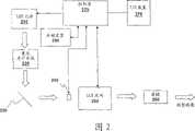
图2示出了根据一个实施例的闭环控制系统的更详细情况。Figure 2 shows more details of the closed loop control system according to one embodiment.
图3示出了根据另一个实施例的利用闭环反馈的系统。Figure 3 illustrates a system utilizing closed loop feedback according to another embodiment.
具体实施方式Detailed ways
在以下说明中,将说明本发明实施例的各方面。然而,对于本领域技术人员,很明显可以使用所述方面中的仅仅一部分或者全部来实现其他实施例。为了进行说明,提出了具体数字、材料和配置,以提供对实施例的彻底理解。然而,对于本领域技术人员,很明显,无需这些具体细节就可以实现其他实施例。在其他例子中,忽略或简化公知的特征,以免使得说明模糊不清。In the following description, aspects of embodiments of the invention will be described. However, it is obvious to those skilled in the art that other embodiments can be implemented using only some or all of the aspects. For purposes of illustration, specific numbers, materials and configurations are set forth to provide a thorough understanding of the embodiments. It will be apparent, however, to one skilled in the art that other embodiments may be practiced without these specific details. In other instances, well-known features were omitted or simplified in order not to obscure the description.
按照最有助于理解实施例的方式,依次将各种操作描述为多个离散操作,然而,不应将说明的顺序理解为暗示这些操作必须依赖于顺序。特别的是,这些操作不必按照提出的顺序而进行。Various operations have been described as multiple discrete operations in turn, in a manner that is most helpful in understanding the embodiments, however, the order of description should not be construed as to imply that these operations are necessarily order dependent. In particular, these operations do not have to be performed in the order presented.
重复使用短语“在一个实施例中”。该短语一般不表示同一实施例,然而,它也可以表示同一实施例。术语“包含”、“具有”和“包括”是同义的,除非上下文表示其他情况。The phrase "in one embodiment" is used repeatedly. The phrase generally does not refer to the same embodiment, however, it may refer to the same embodiment. The terms "comprising," "having," and "including" are synonymous unless the context dictates otherwise.
图1示出了根据一个实施例的能够利用闭环反馈来监测来自一个或更多个发光二极管(LED)光源110的光输出的图像投影系统100的高层位框图。LED光源110向投影光学系统130提供光120。在另选实施例中,可以采用其他固态发光装置。将投影光学系统130广泛定义为包括在对从LED光源110到投影图像160的光120进行处理的各方面中利用的所有光学系统。例如,在一个实施例中,投影光学系统可以包括集光光学系统、折叠镜和光阀。光阀可以包括但不限于数字微镜装置(DMD)、半导体上反射型液晶(LCOS)装置、以及透射或反射型液晶装置(LCD)中的一个或更多个。可以通过光监测元件140对沿着投影光学系统路径的某点处的光进行采样。虽然将光监测元件140示出为投影光学系统130的一部分,但是光监测元件140并不是在所有情况下都是投影光学系统130的一部分。例如,在一个实施例中,可以紧跟在LED光源110之后就对来自LED光源110的光输出进行采样。在这种情况下,可以认为光监测元件140与投影光学系统130分离。在另一实施例中,可以在由投影光学系统130的一部分进行处理之后或者处理过程中对来自LED光源110的光输出进行采样。在特定实施例中,如下所述,光监测元件140可以与投影光学系统130协力工作,以对LED光输出进行采样。可以向处理器150提供通过对LED光输出进行采样而获得的信息。处理器150可以利用此采样信息来控制向LED光源110的供电。1 shows a high-level block diagram of an
图2示出了根据一个实施例的闭环控制系统的更详细情况。LED光源210向集光光学系统220提供光。集光光学系统220向折叠镜230提供聚集的光。折叠镜230向LCD光阀250提供光。在所示出的实施例中,可以在光学照明路径中设置测量装置240,以向控制器270提供反馈。这样,在此实施例中,在到达LCD光阀250之前,从折叠镜230提供的光的一部分被测量装置240吸收。测量装置240吸收的光被转换为电信号,并被作为测得光而提供给控制器270。由此提供的测得光提供了对于LED光源210输出的光的反馈。控制器270可以利用该测得光来确定怎样改变对一个或更多个LED光源210的供电。在另一实施例中,可以在光学照明路径中利用多个测量装置来向控制器270提供反馈。通过LCD光阀250来操作并未由于存在测量装置240而被吸收或反射的光,随后将该光提供给投影透镜260以用于投影。投影透镜260可以包括但不限于固定焦距透镜、变焦透镜(varifocal lens)和连续变焦透镜(zoom lens)。Figure 2 shows more details of the closed loop control system according to one embodiment. The
控制器270对于改变对一个或更多个LED光源210的供电的确定可以基于由一个或更多个来源提供的期望光输出级别(level)来进行。在一个实施例中,控制器270可以通过存储装置290中的存储信息来访问对于LED光源210的期望光输出级别。在一个实施例中,存储装置是ROM,关于期望光输出级别的信息是在制造时确定的。在另一个实施例中,存储装置是非易失存储装置。在该实施例中,在制造时存储缺省值。然而,用户可以通过诸如触摸LCD屏幕的一个或更多个I/O装置275来提供关于LED光源的期望光输出级别的更新信息。可以将该更新信息存储在非易失存储装置中。非易失存储装置可以包括诸如EEPROM、闪存、非易失RAM和读/写光盘的装置。The
在各种其他实施例中,可以利用其他技术来测量LED源的光输出。例如,在一个实施例中,利用杂散光(stray light)来获得对来自LED源的光输出的指示。杂散光是另外的不用于投影图像的光。例如,当核心光通过光学系统时,一些光发生色散并且不可用。可以利用这种色散光来测量来自LED源的光输出。在另一实施例中,在照明路径中设置读取恒定量的光的一个或更多个光学光导管。这些光导管然后可以向控制器提供关于与一个或更多个LED对应的光输出的信息。对光输出的测量可以涉及对多个光子度量之一的测量。光子度量的示例包括流明、坎德拉和英尺烛光、以及亮度。In various other embodiments, other techniques may be utilized to measure the light output of the LED source. For example, in one embodiment, stray light is utilized to obtain an indication of the light output from the LED source. Stray light is additional light that is not used to project an image. For example, when the core light passes through the optical system, some light is dispersed and unusable. This dispersed light can be used to measure the light output from the LED source. In another embodiment, one or more optical light guides that read a constant amount of light are placed in the illumination path. These light pipes can then provide information to the controller about the light output corresponding to the one or more LEDs. Measuring light output may involve measuring one of a number of photon metrics. Examples of photon metrics include lumens, candela and foot-candles, and luminance.
图3示出了根据另一实施例的利用闭环反馈的系统。控制器380从图像数据源395接收图像数据(例如,数据帧)。LED光源310向集光光学系统320提供光。集光光学系统320将光传播到光阀。在示出的实施例中,光阀是数字微镜装置330(DMD)的形式。控制器可以利用图像数据来部分地控制DMD 330的操作。DMD 330可以包括微镜阵列。微镜阵列可以对应于与图像数据相关联的像素信息。在一个实施例中,在DMD 330的工作(例如,在非关闭状态)期间,针对阵列中的各个镜,根据该镜的对应图像数据,入射光325沿两个方向之一投影。在一种情况下,入射光325沿第一方向332反射,以通过投影透镜340投影与对应的图像数据相关联的光。在第二情况下,入射光325沿第二方向334反射到抛弃区域(dump area),从而不通过投影透镜340将其投影。抛弃区域通常是投影系统的涂布有吸光材料的部分。抛弃区域吸收非投影光并使非投影光作为热量消散。这样,当提供数据帧时,与图像像素对应的各个镜将入射光325的对应部分独立地反射到透镜或抛弃区域。Figure 3 shows a system utilizing closed loop feedback according to another embodiment. The
在图3中示出的实施例中,在DMD 330丢弃非投影光的位置设置有三个光检测器360。此外,利用三个滤光器370来对到光检测器360的光进行过滤。例如,在一个实施例中,利用二向色干涉滤光器。在其他实施例中,可以利用其他类型的滤光器,例如其他干涉滤光器或吸收滤光器。在示出的实施例中,三个光检测器360分别检测由二向色干涉滤光器370进行了滤光的原色红光信息、原色绿光信息和原色蓝光信息。In the embodiment shown in FIG. 3, three
将来自三个光检测器360的检测光信息作为电信息发送到控制器380。控制器380对光检测器360的检测光信息进行分析。至少部分地根据该检测光信息,控制器380确定是否向电源390发送更新的控制信息以改变对一个或更多个LED光源310的供电。The detected light information from the three
光检测器360聚集的光可以与LED光输出的总强度成正比。在这种情况下,光检测器360产生的反馈信号也可以与LED光输出成正比。控制器380可以利用反馈信号来将LED光输出的强度或者亮度与对应于期望强度级别的阈值级别(例如期望的级别)进行比较。该期望级别可以存储在控制器380可以访问的存储器中,例如RAM或ROM。如果测得LED光输出的强度大于或小于期望级别,则控制器380可以向电源390提供调整对LED光源310的供电的信息。可以进行该调整以使LED光输出达到期望级别。The light collected by the
在另一实施例中,控制器可以监测光输出,以确定测量到的光输出是否在测量范围内。控制器380充当将反馈信号与已提供给控制器380的表示可接受较高亮度级和较低亮度级的较高阈值和较低阈值进行比较的比较器。例如,照明光路中的各个元件都具有其传送LED光源310产生的光的效率。一旦对这些光学元件进行组装,则系统具有通常在光路中各个位置都恒定的总效率。可以通过公知的分析方法来确定系统额定效率。而且,可以使用公知的分析方法来确定LED光源310产生的光的亮度的变化范围。可以将该结果与系统额定效率相结合以确定亮度级的可接受范围。控制器380将光检测器360产生的反馈信号的幅度与较高亮度范围值和较低亮度范围值进行比较。这些较高亮度范围值和较低亮度范围值可以是与亮度级的可接受范围对应的期望信号值。进行该比较以确定来自LED光源310的光输出的亮度级。如果反馈信号的幅度落在可接受的亮度范围值之外,则控制器380调整从电源390向LED光源310提供的电压,直到反馈信号的幅度落入可接受的亮度范围值。In another embodiment, the controller may monitor the light output to determine whether the measured light output is within the measurement range. The
通过创建电子电路以产生基于前述分析方法的比较所使用的期望输出,或通过基于经验方法,可以设定与测得光输出相关联的期望信号级别。此外,如前所述,可以基于通过用户接口的用户输入来设定期望信号级别,并将其存储在诸如RAM或非易失存储器的系统电子装置中。作为另一种选择,可以通过网络接口385提供期望信号级别。使用网络接口,可以由技术人员远程提供期望信号级别。例如,可以远程利用期望信号级别来诊断与投影系统相关联的问题。在另一实施例中,可以由用户支持中心周期性地提供期望信号级别。这例如可以提供使LED寿命最长的最优值。The desired signal level associated with the measured light output can be set by creating an electronic circuit to produce the desired output for comparison based on the aforementioned analytical methods, or by empirically based methods. Also, as previously mentioned, the desired signal level may be set based on user input through the user interface and stored in system electronics such as RAM or non-volatile memory. Alternatively, the desired signal level may be provided through the
在一个实施例中,实现亮度控制的方法是使用来自光检测器的反馈信号来调整提供给LED光源310的电流。然而,可以使用其他方法。例如,可以使用反馈信号来控制诸如光阀的其他元件,而不是调整向LED光源310的供电。如果LED光输出过高,则可以在显示停留时间的较长时间段关闭光阀,将较多的光送到“抛弃”位置而不是透镜。作为另一种选择,如果LED光输出过低,则可以在显示停留时间的较长时间段打开光阀,将较多的光送到显示屏幕而不是“抛弃”位置。In one embodiment, brightness control is achieved by using a feedback signal from a photodetector to adjust the current supplied to the LED
如前所述,光检测器360的使用产生送往控制器380的反馈。反馈有助于形成闭环系统,以方便对LED光源310或其他系统元件的调整,从而自动保持期望的照明输出。闭环反馈系统的另一用途可以是用于自动颜色校正。在一个实施例中,闭环系统可以按如下方式工作:使用光检测器360产生的反馈信号来自动调整对LED光源310的供电,以使各个LED光源310保持期望的光输出级别。The use of
通常将系统设计为具有提供在特定“白色点”或“色温”的“白”光的光源。这样,当投影装置离开工厂时,光源(例如合在一起的多个LED光源)产生特定色温的光。随着时间推移,光源可能发现其色温改变。在系统具有多个LED光源310的情况下,这种色温改变可能是由于所述多个LED光源310中的一个与其他LED光源310中的一个或更多个相比较按不同的速率改变其光输出。Systems are typically designed with light sources that provide "white" light at a particular "white point" or "color temperature." In this way, when the projection device leaves the factory, the light source (for example, a plurality of LED light sources combined together) generates light with a specific color temperature. Light sources may find their color temperature changes over time. In the case of a system with multiple LED
在本发明的一个实施例中,可以测量LED光源的相对输出。以此方式,可以将各个LED光源产生的光与对应于各个LED光源的测量结果进行比较。根据这些测量结果,可以作出关于各个LED光源输出的期望改变的确定。根据该确定结果,可以改变对各个LED光源的供电,以改进各个LED光源的光输出。In one embodiment of the invention, the relative output of the LED light source can be measured. In this way, the light produced by the individual LED light sources can be compared with the measurement results corresponding to the individual LED light sources. From these measurements, a determination can be made regarding the desired change in output of the individual LED light sources. According to the determination result, the power supply to each LED light source can be changed to improve the light output of each LED light source.
例如,再次参照图3,可以利用滤光器370来过滤与各个LED光源310的输出对应的光。在示出的实施例中,LED光源310对应于原色红色、原色绿色和原色蓝色。利用滤光器370来按照对应于LED光源的方式对光进行分离。这样,发送到控制器380的各个测量读取结果对应于各个发光LED光源310。控制器380可以然后确定测量读取结果表示的各个光输出。控制器可以将各个读取结果与期望的各个级别进行比较。可以按如前所述的各种方式获得期望的各个级别。For example, referring again to FIG. 3 , light corresponding to the output of each
在各种实施例中,可以在各种时间进行对检测的光信息的采样和分析。例如,可以按周期性的间隔进行对检测的光信息的采样。可以针对各个采样进行对此信息的分析,或者可以用在一段时间内进行平均的值来偶尔进行分析。可以按从一个采样到下一个采样提供恒定测量的方式来进行采样。为了实行这种采样,在一个实施例中,在采样期间将DMD330转到全黑。即,在采样期间,操作DMD 330以使得基本上将全部的光都丢弃到抛弃区域。这样,入射在DMD 330上的全部光基本上都被导向光检测器360。这确保光检测器360产生的信号的幅度不受DMD 330的开启或关闭的像素或镜的数量的影响。In various embodiments, sampling and analysis of detected light information may occur at various times. For example, sampling of detected light information may be performed at periodic intervals. Analysis of this information can be done for individual samples, or occasionally with values averaged over a period of time. Sampling may be done in such a way as to provide a constant measurement from one sample to the next. To perform this sampling, in one embodiment, the
采样周期可以根据实施情况而变化。例如,在利用DMD 330的实施例中,可以在一帧的一部分时间将光丢弃到抛弃区域。在这种情况下,从数据源395接收数据帧。在数据帧的第一部分,控制器380利用从数据源395接收的数据来驱动DMD 330以产生要通过透镜340投影的图像。在帧的第二部分,控制器380驱动DMD 330将光丢弃到抛弃区域。在另一个实施例中,在帧的第一部分和第二部分的操作相似。然而,在数据帧的第三部分,控制器380利用从数据源接收的数据来驱动DMD 330以再次产生要通过透镜340投影的图像。The sampling period can vary depending on the implementation. For example, in an
这样,从以上说明可以看出,已经描述了控制LED光源的光输出的方法和如此装备的投影系统。虽然根据前述实施例描述了本发明,但是本领域技术人员可以认识到本发明不限于所描述的实施例。可以在所附权利要求书的精神和范围内有修改和变化地实施其他实施例。因此,应该认为本说明书是示例性的而不是限制性的。Thus, it can be seen from the above description that a method of controlling the light output of an LED light source and a projection system so equipped have been described. While the invention has been described in terms of the foregoing embodiments, those skilled in the art will appreciate that the invention is not limited to the described embodiments. Other embodiments may be practiced with modification and variation within the spirit and scope of the appended claims. Accordingly, the specification should be regarded as illustrative rather than restrictive.
Claims (26)
Applications Claiming Priority (3)
| Application Number | Priority Date | Filing Date | Title |
|---|---|---|---|
| US10/842,898 | 2004-05-10 | ||
| US10/842,898US7172295B2 (en) | 2004-05-10 | 2004-05-10 | LED control system with feedback |
| PCT/US2005/015903WO2005111977A1 (en) | 2004-05-10 | 2005-05-06 | Projection apparatus comprising a led control system with feedback, and driving method therefor |
Publications (2)
| Publication Number | Publication Date |
|---|---|
| CN101006489Atrue CN101006489A (en) | 2007-07-25 |
| CN101006489B CN101006489B (en) | 2013-06-05 |
Family
ID=35239116
Family Applications (2)
| Application Number | Title | Priority Date | Filing Date |
|---|---|---|---|
| CN2005800231575AExpired - Fee RelatedCN101006489B (en) | 2004-05-10 | 2005-05-06 | Projection apparatus comprising a led control system with feedback, and driving method therefor |
| CNU2005200118866UExpired - LifetimeCN2884257Y (en) | 2004-05-10 | 2005-05-10 | Light source control system and device with feedback |
Family Applications After (1)
| Application Number | Title | Priority Date | Filing Date |
|---|---|---|---|
| CNU2005200118866UExpired - LifetimeCN2884257Y (en) | 2004-05-10 | 2005-05-10 | Light source control system and device with feedback |
Country Status (4)
| Country | Link |
|---|---|
| US (1) | US7172295B2 (en) |
| CN (2) | CN101006489B (en) |
| DE (1) | DE202005007409U1 (en) |
| WO (1) | WO2005111977A1 (en) |
Cited By (2)
| Publication number | Priority date | Publication date | Assignee | Title |
|---|---|---|---|---|
| CN109637413A (en)* | 2018-12-26 | 2019-04-16 | 苏州佳世达电通有限公司 | A kind of display device and method promoting the display uniformity |
| CN110858052A (en)* | 2018-08-23 | 2020-03-03 | 深圳光峰科技股份有限公司 | Projector brightness adjusting system and brightness adjusting method |
Families Citing this family (28)
| Publication number | Priority date | Publication date | Assignee | Title |
|---|---|---|---|---|
| US6997900B2 (en)* | 2002-12-09 | 2006-02-14 | Scimed Life Systems, Inc. | Connector for use with a medical catheter and medical catheter assembly |
| JP4665402B2 (en)* | 2004-02-04 | 2011-04-06 | セイコーエプソン株式会社 | Projection type display device, control method for projection type display device, and control program for projection type display device |
| US7538755B2 (en) | 2004-11-02 | 2009-05-26 | Avago Technologies Ecbu Ip (Singapore) Pte. Ltd. | System, method and apparatus using addressable light sensors |
| US7570240B2 (en)* | 2004-12-16 | 2009-08-04 | Lightmaster Systems, Inc. | Method and apparatus to minimize lamp flicker and increase contrast ratio in projection devices |
| US20060226336A1 (en)* | 2005-03-23 | 2006-10-12 | Tir Systems Ltd. | Apparatus and method for collecting and detecting light emitted by a lighting apparatus |
| US7364306B2 (en)* | 2005-06-20 | 2008-04-29 | Digital Display Innovations, Llc | Field sequential light source modulation for a digital display system |
| US20070097358A1 (en)* | 2005-11-01 | 2007-05-03 | Oon Chin H | System and method for obtaining multi-color optical intensity feedback |
| US20090167193A1 (en)* | 2006-11-29 | 2009-07-02 | Panasonic Corporation | Image-processing equipments, image-processing method, program, and recording medium |
| JP4290209B2 (en)* | 2007-04-05 | 2009-07-01 | 三菱電機株式会社 | Image display device and image display method |
| JP5262231B2 (en)* | 2008-03-27 | 2013-08-14 | セイコーエプソン株式会社 | Light source device and image display device |
| DE102009025270B4 (en)* | 2009-06-17 | 2011-03-24 | eyevis Gesellschaft für Projektions- und Grossbildtechnik mbH | Image display device and corresponding operating method |
| US20100328611A1 (en)* | 2009-06-25 | 2010-12-30 | Silverstein Barry D | Leakage light intensity sensing in light projector |
| US8162483B2 (en)* | 2009-06-25 | 2012-04-24 | Eastman Kodak Company | Hierarchical light intensity control in light projector |
| US8220938B2 (en)* | 2009-06-25 | 2012-07-17 | Eastman Kodak Company | Image path light intensity sensing during a blanking period between a left-eye light beam and a right-eye light beam in a stereoscopic light projector |
| US8237777B2 (en)* | 2009-06-25 | 2012-08-07 | Eastman Kodak Company | Stereoscopic image intensity balancing in light projector |
| US8142021B2 (en)* | 2009-06-25 | 2012-03-27 | Eastman Kodak Company | Dump path light intensity sensing in light projector |
| TWI443439B (en)* | 2010-11-22 | 2014-07-01 | Delta Electronics Inc | Projection apparatus, illumination module and brightness adjusting method for the projection apparatus |
| JP5968031B2 (en)* | 2012-04-17 | 2016-08-10 | 三菱電機株式会社 | Laser light source projector |
| CN102751657B (en)* | 2012-06-28 | 2013-10-30 | 华东师范大学 | Laser source system based on accurate and adjustable digital microlens device light intensity |
| JP6398185B2 (en)* | 2013-12-18 | 2018-10-03 | セイコーエプソン株式会社 | Projector and projector control method |
| JP6314553B2 (en)* | 2014-03-07 | 2018-04-25 | 株式会社リコー | Laser light source device and projection display device |
| DE102014110536A1 (en)* | 2014-07-25 | 2016-01-28 | E. Zoller GmbH & Co. KG Einstell- und Messgeräte | overhead projector |
| CN106796385A (en)* | 2014-07-31 | 2017-05-31 | 惠普发展公司,有限责任合伙企业 | Image projection and capture with the adjustment for white point |
| WO2016018372A1 (en)* | 2014-07-31 | 2016-02-04 | Hewlett-Packard Development Company, L.P. | White flash generation from a light emitting diode (led) projector |
| DE102016209648A1 (en)* | 2016-06-02 | 2017-12-07 | Osram Gmbh | Lighting device with sensor on the absorber |
| DE102017213102A1 (en)* | 2017-07-28 | 2019-01-31 | Osram Gmbh | LIGHTING DEVICE WITH A LIGHTING SOURCE FOR THE LIGHTING OF LIGHTING LIGHT |
| DE102017220056A1 (en)* | 2017-11-10 | 2019-05-16 | Osram Gmbh | LIGHTING DEVICE WITH LIGHT SOURCE |
| DE102018133289A1 (en)* | 2018-12-21 | 2020-06-25 | Hensoldt Optronics Gmbh | Measuring device and method for determining the minimum resolvable contrast |
Family Cites Families (16)
| Publication number | Priority date | Publication date | Assignee | Title |
|---|---|---|---|---|
| US3571493A (en)* | 1967-10-20 | 1971-03-16 | Texas Instruments Inc | Intensity modulated laser imagery display |
| US6535187B1 (en)* | 1998-04-21 | 2003-03-18 | Lawson A. Wood | Method for using a spatial light modulator |
| US6285491B1 (en) | 1998-12-28 | 2001-09-04 | Texas Instruments Incorporated | Adaptive temporal modulation of periodically varying light sources |
| JP2000227561A (en)* | 1999-02-05 | 2000-08-15 | Toshiba Corp | Projection display device |
| JP3983950B2 (en)* | 1999-12-28 | 2007-09-26 | 株式会社東芝 | Projection display |
| US6224216B1 (en)* | 2000-02-18 | 2001-05-01 | Infocus Corporation | System and method employing LED light sources for a projection display |
| US6472828B1 (en)* | 2000-06-23 | 2002-10-29 | Infocus Corporation | Control for projector lamp heat dissipation |
| US6474818B1 (en)* | 2000-07-28 | 2002-11-05 | Infocus Corporation | Mirror and aperture based color phase detector for use in a multimedia projection system |
| US6520648B2 (en)* | 2001-02-06 | 2003-02-18 | Infocus Corporation | Lamp power pulse modulation in color sequential projection displays |
| JP3640173B2 (en)* | 2001-04-02 | 2005-04-20 | ソニー株式会社 | Image display device |
| US6585343B2 (en)* | 2001-10-31 | 2003-07-01 | Hewlett-Packard Development Company, L.P. | System and method for using pulse or trickle warming to control neutral color balance on a print media |
| JP2003279887A (en)* | 2002-03-22 | 2003-10-02 | Nec Viewtechnology Ltd | Dmd projector and video signal correcting method therefor |
| US6666896B1 (en)* | 2002-09-09 | 2003-12-23 | Rockwell Collins, Inc. | Projection display having a high reliability illumination system |
| JP2004184852A (en)* | 2002-12-05 | 2004-07-02 | Olympus Corp | Display device, light source device, and lighting device |
| JP4016876B2 (en)* | 2003-04-23 | 2007-12-05 | セイコーエプソン株式会社 | projector |
| US7055962B2 (en)* | 2003-11-21 | 2006-06-06 | Dell Products L.P. | System and method for managing projector bulb life |
- 2004
- 2004-05-10USUS10/842,898patent/US7172295B2/ennot_activeExpired - Lifetime
- 2005
- 2005-05-06CNCN2005800231575Apatent/CN101006489B/ennot_activeExpired - Fee Related
- 2005-05-06WOPCT/US2005/015903patent/WO2005111977A1/enactiveApplication Filing
- 2005-05-10CNCNU2005200118866Upatent/CN2884257Y/ennot_activeExpired - Lifetime
- 2005-05-10DEDE202005007409Upatent/DE202005007409U1/ennot_activeExpired - Lifetime
Cited By (2)
| Publication number | Priority date | Publication date | Assignee | Title |
|---|---|---|---|---|
| CN110858052A (en)* | 2018-08-23 | 2020-03-03 | 深圳光峰科技股份有限公司 | Projector brightness adjusting system and brightness adjusting method |
| CN109637413A (en)* | 2018-12-26 | 2019-04-16 | 苏州佳世达电通有限公司 | A kind of display device and method promoting the display uniformity |
Also Published As
| Publication number | Publication date |
|---|---|
| DE202005007409U1 (en) | 2005-11-03 |
| CN2884257Y (en) | 2007-03-28 |
| CN101006489B (en) | 2013-06-05 |
| WO2005111977A1 (en) | 2005-11-24 |
| US7172295B2 (en) | 2007-02-06 |
| US20050248737A1 (en) | 2005-11-10 |
Similar Documents
| Publication | Publication Date | Title |
|---|---|---|
| CN101006489B (en) | Projection apparatus comprising a led control system with feedback, and driving method therefor | |
| JP5213078B2 (en) | Projector, projection image brightness adjustment method, and program | |
| US8979278B2 (en) | Light source device and projection apparatus which adjusts a light emission state of first and second light sources based on one of detected light intensity values and an accumulated light emission time, and projection method and non-transitory storage medium | |
| KR100609273B1 (en) | Light control method for digital mirror projector and digital mirror projector | |
| US7278745B2 (en) | Method and apparatus for adjusting relative disposition of projection optics based on operating conditions | |
| US6788469B2 (en) | Automated lamp focus | |
| JP2004296841A (en) | Projection display device, illumination device, and method for measuring element characteristics of semiconductor light source for display device | |
| KR20090105642A (en) | Display device and light control method | |
| CN108172156A (en) | A projector intelligent projection control system and method | |
| JP4433320B2 (en) | Projector and control method thereof | |
| JP2007293195A (en) | Projector with automatic luminance adjustment mechanism, and automatic luminance adjustment method | |
| TW200820768A (en) | Adaptive emission frame projection display and method | |
| US20100014000A1 (en) | Automatic Color Adjustment Method and An Automatic Color Adjustment Device | |
| JP5655265B2 (en) | Projector, image quality adjustment method, image quality adjustment program, and recording medium | |
| JP2007328074A (en) | Light source control device | |
| US20120133896A1 (en) | Projection-type Image Display Device | |
| JPWO2019017051A1 (en) | Light source system, control device, and control method | |
| JP2008224870A (en) | Projector and its control method | |
| JP2017146433A (en) | Image projection device | |
| JP4193595B2 (en) | Projection display | |
| CN101315513B (en) | Projection display device and method for controlling off-beams thereof | |
| US11877101B2 (en) | Image display apparatus | |
| CN112866658B (en) | Image projection apparatus | |
| US20250133193A1 (en) | Image projection apparatus, image projection method, and non-transitory recording medium | |
| JP5652500B2 (en) | Light source device, projection device, projection method and program |
Legal Events
| Date | Code | Title | Description |
|---|---|---|---|
| C06 | Publication | ||
| PB01 | Publication | ||
| C10 | Entry into substantive examination | ||
| SE01 | Entry into force of request for substantive examination | ||
| ASS | Succession or assignment of patent right | Owner name:SEIKO EPSON CORP. Free format text:FORMER OWNER: RPX COMPANY Effective date:20100604 Owner name:RPX COMPANY Free format text:FORMER OWNER: INFOCUS CO., LTD. Effective date:20100604 | |
| C41 | Transfer of patent application or patent right or utility model | ||
| COR | Change of bibliographic data | Free format text:CORRECT: ADDRESS; FROM: OREGON, USA TO: CALIFORNIA, USA Free format text:CORRECT: ADDRESS; FROM: CALIFORNIA, USA TO: TOKYO, JAPAN | |
| TA01 | Transfer of patent application right | Effective date of registration:20100604 Address after:Tokyo, Japan Applicant after:Seiko Epson Corp. Address before:California, USA Applicant before:RPX Corp. Effective date of registration:20100604 Address after:California, USA Applicant after:RPX Corp. Address before:oregon Applicant before:Infocus Corp. | |
| C14 | Grant of patent or utility model | ||
| GR01 | Patent grant | ||
| CF01 | Termination of patent right due to non-payment of annual fee | ||
| CF01 | Termination of patent right due to non-payment of annual fee | Granted publication date:20130605 |