CN101006209B - Apparatus and method for melt spinning, drawing, handling and winding a plurality of synthetic filaments - Google Patents
Apparatus and method for melt spinning, drawing, handling and winding a plurality of synthetic filamentsDownload PDFInfo
- Publication number
- CN101006209B CN101006209BCN2005800277367ACN200580027736ACN101006209BCN 101006209 BCN101006209 BCN 101006209BCN 2005800277367 ACN2005800277367 ACN 2005800277367ACN 200580027736 ACN200580027736 ACN 200580027736ACN 101006209 BCN101006209 BCN 101006209B
- Authority
- CN
- China
- Prior art keywords
- spinning
- thread
- threads
- processing
- plane
- Prior art date
- Legal status (The legal status is an assumption and is not a legal conclusion. Google has not performed a legal analysis and makes no representation as to the accuracy of the status listed.)
- Expired - Fee Related
Links
Images


Classifications
- D—TEXTILES; PAPER
- D01—NATURAL OR MAN-MADE THREADS OR FIBRES; SPINNING
- D01D—MECHANICAL METHODS OR APPARATUS IN THE MANUFACTURE OF ARTIFICIAL FILAMENTS, THREADS, FIBRES, BRISTLES OR RIBBONS
- D01D13/00—Complete machines for producing artificial threads
- D—TEXTILES; PAPER
- D01—NATURAL OR MAN-MADE THREADS OR FIBRES; SPINNING
- D01D—MECHANICAL METHODS OR APPARATUS IN THE MANUFACTURE OF ARTIFICIAL FILAMENTS, THREADS, FIBRES, BRISTLES OR RIBBONS
- D01D13/00—Complete machines for producing artificial threads
- D01D13/02—Elements of machines in combination
Landscapes
- Engineering & Computer Science (AREA)
- Mechanical Engineering (AREA)
- Textile Engineering (AREA)
- Spinning Methods And Devices For Manufacturing Artificial Fibers (AREA)
Abstract
Description
Translated fromChinese技术领域technical field
本发明涉及一种用于熔融纺丝、抽出、处理和卷绕多个合成丝线的设备和一种用于熔融纺丝、抽出、处理和卷绕多个合成丝线的方法。The present invention relates to an apparatus for melt spinning, drawing, treating and winding a plurality of synthetic threads and a method for melt spinning, drawing, treating and winding a plurality of synthetic threads.
背景技术Background technique
一种同类的设备以及一种同类的方法例如由DE 44 16 136 A1已知。A similar device and a similar method are known, for example, from DE 44 16 136 A1.
在该已知的设备和已知的方法中,在一个纺丝装置中保持多个以列式结构形式的纺丝喷嘴。通过每个纺丝喷嘴挤出许多单丝作为单丝束并且通过一个设置在纺丝喷嘴下方的冷却装置用冷却剂进行冷却。在单丝冷却之后进行由每个纺丝喷嘴产生的单丝束的通过上油装置的合并。在此通过一种上油剂实现在各单丝之间成为一个丝线的粘结。各丝线作为一个丝线束共同通过一个设置在冷却装置下方的抽出机构连续地从纺丝喷嘴中抽出并且在处理之后分别卷绕成筒子。In the known device and the known method, a plurality of spinning nozzles are held in a row arrangement in a spinning device. A plurality of filaments are extruded through each spinning nozzle as a bundle of filaments and cooled with a coolant by a cooling device arranged below the spinning nozzles. Combination of the filament bundles produced by each spinning nozzle by means of an oiling device takes place after the filaments have cooled. In this case, the bond between the individual filaments to form a thread is achieved by means of an oiling agent. The individual threads are drawn together as a thread bundle continuously from the spinning nozzle by means of a withdrawal mechanism arranged below the cooling device and are individually wound into bobbins after processing.
因为各丝线在抽出和处理时的引导间距和处理间距明显小于在纺丝装置中的丝线间距,所以各丝线在从纺丝装置至抽出机构的过渡中必须非常强烈地偏转和聚集。各丝线的偏转在此取决于各丝线在纺丝装置中的间距以及平行并排纺丝的丝线的数量。在此要注意最大允许的偏转角,以便不会在导丝时特别是在外面的丝线中产生大的包缠差别,这必然导致在制造的丝线中的物理差别。这种允许的在小于7°范围内的偏转可以相应地仅通过在纺丝装置与抽出机构之间的相应长的区域减小。但是在实践中期望在单丝束的汇聚点与抽出机构位置之间的尽可能小的间距,因此在丝线束聚集时具有不同包缠的导丝几乎不能避免。另外期望由于价格和操作原因设备的结构高度保持为有限的。但是因此问题在于,丝线在运动进入处理机构时在丝线张力和丝线紧密度方面处于不均匀的条件中。Since the guiding and handling distances of the individual threads during withdrawal and processing are significantly smaller than the thread spacing in the spinning device, the individual threads must be deflected and converged very strongly during the transition from the spinning device to the withdrawal mechanism. The deflection of the individual threads depends here on the spacing of the individual threads in the spinning device and on the number of threads spun parallel to each other. Attention should be paid to the maximum permissible deflection angle in this case, so that no large wrapping differences occur during wire guidance, especially in the outer wires, which necessarily lead to physical differences in the manufactured wires. This permissible deflection in the range of less than 7° can correspondingly be reduced only by a correspondingly long region between the spinning device and the withdrawal mechanism. In practice, however, it is desirable to have as small a distance as possible between the point of convergence of the individual filament bundles and the position of the withdrawal mechanism, so guide wires with different wrappings during the convergence of the filament bundles can hardly be avoided. It is also desirable for the structural height of the device to remain limited for price and handling reasons. However, it is therefore problematic that the thread is in uneven conditions with respect to thread tension and thread tightness when it is moved into the handling mechanism.
发明内容Contents of the invention
本发明的目的是实现一种开头所述类型的用于熔融纺丝、抽出和卷绕多个合成丝线的设备和方法,其中各平行纺丝的丝线尽管聚集到一个较窄的丝线间距仍能尽可能在均匀的条件下进行引导。The object of the present invention is to realize a device and a method for melt spinning, withdrawing and winding a plurality of synthetic threads of the type mentioned at the outset, in which the threads spun in parallel can be produced despite being gathered to a narrow thread spacing Boot in as uniform conditions as possible.
本发明的目的同样是进一步改进一种同类的设备和一种同类的方法,使得即使在许多平行纺丝的丝线的情况下,用于实现纺丝设备的紧凑结构形式的导丝也是可能的。It is likewise the object of the invention to further develop a similar device and a similar method so that even with many threads spun in parallel, a guide wire in a compact design for realizing the spinning device is possible.
本发明的另一目的是在采用许多纺丝喷嘴的情况下在从纺丝装置至处理装置的过渡中实现尽可能小的偏转角。A further object of the invention is to achieve as small a deflection angle as possible in the transition from the spinning device to the processing device when using a large number of spinning nozzles.
本发明提供一种用于熔融纺丝、抽出、处理和卷绕多个合成丝线的设备,包括一个具有多个并排设置的纺丝喷嘴的纺丝装置、一个配设于各纺丝喷嘴的冷却装置以及在丝线流程中设置于冷却装置下方的抽出机构、一个处理机构和一个卷绕装置,其特征在于:在冷却装置下方设置多个抽出机构,每个抽出机构配设一组纺丝喷嘴并且各抽出机构与设置在后面的处理机构相互作用,使得各丝线能作为一个具有平行运动的丝线的丝线束引导通过处理机构,所述处理机构设置在抽出机构侧面旁边或侧面上方,在每个抽出机构前面设置多个汇集导丝器之一,配设于抽出机构的丝线通过汇集导丝器能从纺丝喷嘴的分布间距引导到引导间距。The invention provides a kind of equipment for melt spinning, extracting, processing and winding a plurality of synthetic yarns, comprising a spinning device with a plurality of spinning nozzles arranged side by side, a cooling device arranged at each spinning nozzle The device and the drawing-out mechanism, a processing mechanism and a winding device arranged under the cooling device in the thread process are characterized in that: a plurality of drawing-out mechanisms are arranged under the cooling device, and each drawing-out mechanism is equipped with a group of spinning nozzles and Each withdrawal mechanism interacts with a subsequent handling mechanism, so that each thread can be guided through the handling mechanism as a bundle of threads with parallel movements, said handling mechanism being arranged beside or above the side of the withdrawal mechanism, at each withdrawal One of a plurality of collecting yarn guides is arranged in front of the mechanism, and the filaments arranged in the drawing-out mechanism can be guided from the distribution pitch of the spinning nozzles to the guiding pitch through the collection yarn guides.
本发明提供一种用于熔融纺丝、抽出、处理和卷绕多个合成丝线的方法,包括以下步骤:平行并排地挤出和冷却多个单丝束并且将其中每个单丝束分别聚集成其中一个丝线;将各丝线分成至少两组丝线并且通过独立的抽出机构抽出每组丝线,通过在每个抽出机构前面设置的一个汇集导丝器将丝线从纺丝喷嘴的分布间距引导到引导间距;各丝线组聚集成一个具有平行运动的丝线的丝线束并且通过一个处理机构承接丝线束用以处理,所述处理机构设置在抽出机构侧面旁边或侧面上方;和将丝线束的丝线卷绕成筒子。The present invention provides a method for melt spinning, drawing, handling and winding a plurality of synthetic filaments comprising the steps of extruding and cooling a plurality of monofilament bundles in parallel side by side and gathering each of the monofilament bundles separately into one of the filaments; each filament is divided into at least two groups of filaments and each group of filaments is drawn out by an independent withdrawal mechanism, and the filaments are guided from the distribution pitch of the spinning nozzle to the guide by a collection yarn guide arranged in front of each withdrawal mechanism. Spacing; the groups of wires are gathered into a bundle of wires with parallel movement and are received for processing by a handling mechanism positioned beside or above the side of the withdrawal mechanism; and winding the wires of the bundle Into a bobbin.
本发明的特点在于,各纺丝的丝线在多个阶段中聚集成一个共同的待处理的丝线束。为此在冷却装置下方设置多个抽出机构,其中每个抽出机构配设一组纺丝喷嘴。因此许多纺丝的丝线有利地分成两组或更多组,它们分别通过独立的抽出机构抽出。各抽出机构与设置在后面的处理机构这样相互作用,使得在各组丝线抽出之后所有丝线可以共同作为一个丝线束引导通过处理机构。本发明重要的优点在于,既使在许多同时纺丝的丝线的情况下在单丝束的基本上设置在一高度上的各会聚点与抽出机构的位置之间的间距也可以设置成技术上可实现的最小间距。单丝束的会聚点在此是在丝线的丝线流程中的将该单丝束聚集成丝线的位置。在单丝束的会聚点与抽出机构的位置之间的区域被各丝线相对倾斜地通过,使得这些区域不适合于共同处理各丝线并且从而按本发明可以构成为特别短的。The invention is characterized in that the individual spun threads are gathered in several stages to form a common thread bundle to be processed. For this purpose, a plurality of draw-offs are arranged below the cooling device, wherein each draw-off is associated with a group of spinning nozzles. The many spun threads are thus advantageously divided into two or more groups, which are each withdrawn by means of separate withdrawal mechanisms. The respective withdrawal means interact with the downstream handling means in such a way that after withdrawal of the individual groups of threads, all the threads can be guided together as a thread bundle through the handling means. An important advantage of the present invention is that even in the case of many simultaneously spun filaments, the spacing between the points of convergence of the monofilament bundles that are arranged substantially at a height and the position of the withdrawal mechanism can be set to technically Minimum achievable spacing. The point of convergence of the filament bundle is here the point in the thread run of the thread at which the filament bundle is gathered to form a filament. The regions between the point of convergence of the monofilament bundles and the position of the withdrawal mechanism are traversed by the filaments at an angle relative to each other, so that these regions are not suitable for joint processing of the filaments and can therefore be designed particularly short according to the invention.
为了在丝线组内得到尽可能均匀的偏转和包缠,抽出机构按本发明的一种有利的进一步拓展优选在相配的纺丝喷嘴组下方设置成对称的。In order to achieve as uniform a deflection and wrapping as possible within the yarn group, the withdrawal means are preferably arranged symmetrically below the associated spinning nozzle group according to an advantageous further development of the invention.
在本发明另一优选的进一步拓展中,丝线在挤出之后在一个共同的纺丝平面内引导并且为了处理在一个基本上垂直于该纺丝平面地定向的处理平面内引导。在此通过纺丝装置的纺丝喷嘴预定的丝线运动平面称为纺丝平面。处理平面是所有丝线的共同的通过处理机构确定的丝线运动平面。为了在抽出机构的布置中得到附加的自由度,抽出机构可以平行于纺丝平面或者平行于处理平面或者在一个中间平面内引导丝线组。In another preferred further development of the invention, the threads are guided after extrusion in a common spinning plane and for processing in a treatment plane oriented substantially perpendicularly to the spinning plane. The plane of movement of the threads predetermined by the spinning nozzles of the spinning device is referred to here as the spinning plane. The processing plane is a common thread movement plane for all threads which is determined by the processing mechanism. In order to obtain an additional degree of freedom in the arrangement of the withdrawal means, the withdrawal means can guide the thread group parallel to the spinning plane or parallel to the processing plane or in an intermediate plane.
在此抽出机构优选设置在处理机构前面,使得每个丝线可以用同样大小的丝线包缠进行引导。因此保证在制造合成丝线时高的均匀性。In this case, the withdrawal means are preferably arranged upstream of the handling means, so that each thread can be wrapped and guided with a thread of the same size. This ensures high uniformity in the manufacture of the synthetic yarn.
为了允许各组丝线平行地运动进入抽出机构,在每个抽出机构前面优选设置一个汇集导丝器(Sammelfadenführer),借此丝线可以从纺丝喷嘴的分布间距引导到优选窄的引导间距。In order to allow the parallel movement of the individual groups of threads into the withdrawal means, a converging thread guide is preferably arranged upstream of each withdrawal means, whereby the threads can be guided from the distribution distance of the spinning nozzles to a preferably narrow guidance distance.
为了特别是对于丝线的处理在丝线中加强的丝线紧密度占优势,按本发明的一种优选的进一步拓展建议,在汇集导丝器和抽出机构之间分别设置一个预缠结装置(Vortangeleinrichtung)。由于偏转而此前失去的或不均匀的上油涂覆因此可以得到补偿或均匀化。同样丝线张力在运动到抽出机构上之前在平行运动的丝线上得到均匀化。According to a preferred further development of the invention, a pre-entanglement device (Vortangeleinrichtung) is arranged in each case between the collecting yarn guide and the withdrawal mechanism in order to predominate in the enhanced yarn compactness in the yarn, especially for the treatment of the yarn. . A previously lost or uneven oiling application due to the deflection can thus be compensated or evened out. Likewise, the thread tension is equalized on the parallel moving thread prior to its movement to the withdrawal mechanism.
抽出机构优选分别通过一个被驱动的导丝辊构成,其中导丝辊的导丝辊驱动装置可以同步地控制。The withdrawal means are each preferably formed by a driven godet, wherein the godet drives of the godets can be controlled synchronously.
为了在引导丝线组时得到尽可能小的差别,导丝辊的导丝辊驱动装置优选通过一个组变频器进行控制。In order to obtain as little difference as possible when guiding the thread groups, the godet drive of the godet is preferably controlled via a group frequency converter.
但是各导丝辊分别配设一个超越辊
取而代之或者与之相结合,在抽出聚集的丝线束之后要平行运动的丝线的处理可以是拉伸、缠结、调温或并合。优选各丝线在卷绕之前以不同的方式方法拉伸,使得在抽出机构后面优选设置一个被驱动的例如用于制造POY丝线的拉伸导丝辊(Streckgalette)或至少一个被驱动的用于拉伸丝线的双导丝辊(Galettenduo)作为处理机构。Alternatively or in combination therewith, the processing of the threads to be moved parallel after the withdrawal of the gathered thread bundle can be stretching, entanglement, tempering or merging. Preferably, the individual threads are drawn in different ways before winding, so that a driven stretching godet (streckgalette) or at least one driven stretching godet (for example for producing POY threads) or at least one driven stretching godet (streckgalette) or at least one The twin godet rolls (Galettenduo) of the drawing line are used as the processing mechanism.
但是处理机构也可以单独地通过一个缠结装置构成,它包含处理间距小于10mm的多个丝线处理通道,这特别是在前置或后置的通过导丝辊的引导的情况下引出相应大的铺设密度(Belegungsdichte)。However, the treatment mechanism can also be formed separately by a entanglement device, which contains a plurality of yarn treatment channels with a treatment distance of less than 10 mm, which leads to correspondingly large yarns especially in the case of front or rear guidance by godet rollers. Laying density (Belegungsdichte).
优选缠结装置在丝线流程中设置在拉伸导丝辊的前面,因此可以调节和选择有利于丝线卷绕的丝线张力。缠结装置在丝线流程中在拉伸导丝辊前面的布置另外具有如下优点,即在单次或多次包缠拉伸导丝辊的情况下由于小的丝线间距使得伸出的长度保持较小。Preferably, the entanglement device is arranged in front of the drawing godet in the thread flow, so that the thread tension can be adjusted and selected to facilitate the winding of the thread. The arrangement of the entanglement device in the thread flow upstream of the drawing godet also has the advantage that the protruding length is kept relatively small due to the small distance between the threads when wrapping the drawing godet in one or multiple wraps. Small.
另外为了制造具有高的物理特性均匀性的微单丝(Mikrofilament)建议一个冷却装置,该冷却装置对于每个纺丝喷嘴具有一个风筒(Blaskerze)。在此通过风筒分别产生一个沿径向从内到外指向的冷却气流,用于冷却其中一个纺丝喷嘴的环形引导的单丝束。Furthermore, for the production of microfilaments with a high uniformity of physical properties, a cooling device is proposed which has a blower for each spinning nozzle. In this case, a cooling air flow directed radially from the inside to the outside is generated in each case via the fan cylinders for cooling the annularly guided filament bundle of one of the spinning nozzles.
在此单丝束可以不仅引导成一个丝线,也可以引导成多个丝线。为了由一个单丝束构成多个丝线,优选采用这样一个上油装置,该上油装置对于每个纺丝喷嘴具有多个上油导丝器。因此环形的单丝束可以转变成多个丝线。In this case, the monofilament bundle can be guided not only into one thread, but also into several threads. In order to form a plurality of threads from a single filament bundle, an oiling device is preferably used which has a plurality of oiling yarn guides per spinning nozzle. A circular monofilament bundle can thus be converted into a plurality of filaments.
附图说明Description of drawings
下面借助于图1至3详细解释本发明设备和本发明方法的一些实施例。其中:Some exemplary embodiments of the device according to the invention and the method according to the invention are explained in detail below with the aid of FIGS. 1 to 3 . in:
图1示意描述用于执行本发明方法的本发明设备的第一实施例;Fig. 1 schematically depicts a first embodiment of the apparatus of the invention for carrying out the method of the invention;
图2示意描述本发明设备的第二实施例;Fig. 2 schematically depicts a second embodiment of the apparatus of the present invention;
图3示意描述本发明设备的另一实施例。Figure 3 schematically depicts another embodiment of the device of the invention.
具体实施方式Detailed ways
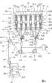
在图1中示意显示本发明的用于熔融纺丝、抽出、处理和卷绕多个合成丝线的设备。该设备为了制造多个丝线而具有一个纺丝装置1、一个设置在纺丝装置1后面的冷却装置2以及一个用于卷绕丝线的卷绕装置3。An apparatus according to the invention for melt spinning, drawing, processing and winding a plurality of synthetic filaments is schematically shown in FIG. 1 . For the production of threads, the device has a
纺丝装置1具有多个平行并排设置的纺丝喷嘴8.1至8.6。纺丝喷嘴8.1至8.6保持在可加热的纺丝箱体7的底面上。纺丝箱体7包含多个在此未示出的纺丝泵和熔体分配器,它们经由一个熔体入口12与一个熔体源例如一个挤出机连接。纺丝喷嘴8.1至8.6在其底面具有一个由许多喷嘴开口构成的环形结构,通过各喷嘴开口可以挤出许多单丝。The
在纺丝装置1下方设置一个冷却装置2,该冷却装置通过在冷却甬道34内的许多风筒10.1至10.6构成。风筒10.1至10.6在中间配设于纺丝喷嘴8.1至8.6,其中通过纺丝喷嘴8.1至8.6挤出的单丝作为环形引导的单丝束呈外套形地包围相应配设的风筒10.1至10.6。风筒10.1至10.6的底面与冷却空气源连接。Below the
直接在冷却装置2下方设置一个上油装置4,该上油装置具有多个配设于纺丝喷嘴8.1至8.6的上油导丝器11.1至11.6。Arranged directly below the
在上油装置4下方设置两个彼此隔开距离地设置的抽出机构5.1和5.2。抽出机构5.1在此通过第一导丝辊13.1构成,该第一导丝辊在垂直方向上配设于纺丝喷嘴8.1、8.2和8.3,以便从纺丝装置1中抽出第一组丝线35.1。Arranged below the
第二抽出机构5.2通过第二导丝辊13.2构成,该第二导丝辊在垂直方向上配设于纺丝喷嘴8.4、8.5和8.6,以便从纺丝装置1中抽出第二组丝线35.2。导丝辊13.1和13.2经由导丝辊驱动装置14.1和14.2驱动。为了控制导丝辊驱动装置14.1和14.2设置一个组变频器15。The second withdrawal mechanism 5.2 is formed by a second godet 13.2, which is arranged vertically to the spinning nozzles 8.4, 8.5 and 8.6, in order to withdraw the second group of threads 35.2 from the
在抽出机构5.1前面设置一个第一丝线导向杆16.1、一个汇集导丝器17.1和一个预缠结装置18.1。第二抽出机构5.2配设一个第二丝线导向杆16.2、一个汇集导丝器17.2和一个预缠结装置18.2。Arranged upstream of the withdrawal mechanism 5.1 is a first thread guide rod 16.1, a collecting thread guide 17.1 and a pre-entanglement device 18.1. The second withdrawal mechanism 5.2 is assigned a second thread guide rod 16.2, a collection thread guide 17.2 and a pre-entanglement device 18.2.
在抽出机构5.1和5.2侧面旁边设置一个处理机构6,该处理机构通过一个主缠结装置21和拉伸导丝辊19构成。在此主缠结装置21在丝线流程中直接设置在拉伸导丝辊19前面。为了输出在拉伸导丝辊19上部分包缠地引导的丝线,设置一个输出导丝器22,丝线通过该输出导丝器在从拉伸导丝辊19输出时保持一个处理间距。拉伸导丝辊19通过一个导丝辊驱动装置14.3驱动。Next to the withdrawal devices 5 . 1 and 5 . 2 is arranged a
在处理机构6下方设置卷绕装置3。卷绕装置3在丝线运动方向上具有一个往复装置24、一个压靠辊25和一个第一管筒锭子26.1。丝线在管筒锭子26.1上卷绕成筒子27。管筒锭子26.1保持在一个转盘28上,该转盘携带一个相对于管筒锭子26.1错开180°的第二管筒锭子26.2。为了导丝,在往复装置24前面对于每个丝线分别设置一个顶端导丝器23。Below the handling mechanism 6 a winding
在图1中描述的设备特别适用于制造所谓的POY丝线。为此在每个纺丝喷嘴8.1至8.6上将一个预定的聚合物熔体分别挤出成为一个单丝束9.1至9.6。每个单丝束9.1至9.6通过一个沿径向由风筒10.1至10.6从内向外指向的冷却介质流进行冷却并且在冷却后分别通过一个上油导丝器11.1至11.6合并成一根丝线。通过纺丝喷嘴8.1至8.3挤出的丝线是第一组丝线35.1,它们通过抽出机构5.1从纺丝装置1中抽出。纺丝喷嘴8.4至8.6是第二组丝线35.2,它们通过第二抽出机构5.2从纺丝装置中抽出。在此两组丝线35.1和35.2在单丝束合并的情况下在一个共同的纺丝平面内引导。与此相对,通过所有丝线构成的丝线束36在处理机构6中引导到一个处理平面内,该处理平面基本上垂直于纺丝平面地定向。为此有必要使丝线从纺丝装置1或上油装置4过渡到处理机构6旋转大约90°。The apparatus described in FIG. 1 is particularly suitable for the manufacture of so-called POY threads. For this purpose, a predetermined polymer melt is extruded on each spinning nozzle 8.1 to 8.6 to form a filament strand 9.1 to 9.6 respectively. Each filament bundle 9.1 to 9.6 is cooled by a cooling medium flow directed radially from the inside to the outside by the fan cylinders 10.1 to 10.6 and is combined to form a thread after cooling by an oiling yarn guide 11.1 to 11.6 respectively. The threads extruded through the spinning nozzles 8.1 to 8.3 are the first group of threads 35.1 which are withdrawn from the
为了将第一组丝线35.1从纺丝平面中引出,在第一抽出机构5.1前面设置一个丝线导向杆16.1和一个汇集导丝器17.1。第一组丝线35.1通过汇集导丝器17.1从一个由相邻纺丝喷嘴8.1至8.6的间距确定的分布间距变成为一个引导间距。丝线之间的引导间距从汇集导丝器17.1直至处理机构6基本上保持恒定。在丝线从汇集导丝器17.1运动到第一导丝辊13.1上之前,在预缠结装置18.1中进行各丝线的涡流变形。这种预缠结装置例如由DE 100 23 910 A1已知,因此在此可以参考该引用的文献。In order to draw the first group of threads 35.1 out of the spinning plane, a thread guide rod 16.1 and a collecting thread guide 17.1 are arranged upstream of the first withdrawal mechanism 5.1. The yarns 35.1 of the first group are changed from a distribution pitch determined by the distance between adjacent spinning nozzles 8.1 to 8.6 to a guide pitch via the converging thread guide 17.1. The guiding distance between the threads remains substantially constant from the collecting thread guide 17 . 1 to the
为了将第二组丝线35.2从纺丝平面中引出,设置第二丝线导向杆16.2和第二汇集导丝器17.2。在此第二组丝线35.2通过汇集导丝器17.2同样从分布间距变成为引导间距。In order to guide the second group of threads 35.2 out of the spinning plane, a second thread guide bar 16.2 and a second collecting thread guide 17.2 are provided. Here too, the second group of threads 35.2 is changed from a distribution pitch to a guide pitch by means of the converging thread guide 17.2.
为了抽出两组丝线35.1和35.2,导丝辊13.1和13.2用相同的圆周速度进行驱动。为此导丝辊驱动装置14.1和14.2通过一个组变频器15进行控制。In order to withdraw the two sets of threads 35.1 and 35.2, the godets 13.1 and 13.2 are driven with the same peripheral speed. Godet drives 14 . 1 and 14 . 2 are controlled via a
两组丝线35.1和35.2通过随后的处理机构6从抽出机构5.1和5.2抽出。在此拉伸导丝辊19用一个优选略大于导丝辊13.1和13.2的圆周速度的圆周速度进行驱动。第一组丝线35.1在此在部分包缠导丝辊13.1之后直接引导至处理机构6。第二组丝线35.2在部分包缠第二导丝辊13.2之后并且在部分包缠第一导丝辊13.1之后引导至处理机构6,使得在从第一导丝辊13.1输出之后,第一组和第二组丝线35.1和35.2构成一个共同的丝线束36。第二组丝线35.2在导丝辊13.2和13.1上的包缠角相同于第一组丝线35.1在导丝辊13.1上的包缠角。因此所有丝线在运动进入丝线束36时以相同的包缠角进行引导。The two sets of threads 35.1 and 35.2 are withdrawn by the
丝线束36的丝线首先在主缠结装置21中平行并排地进行涡流变形。为此主缠结装置21具有多个平行延伸的丝线处理通道,在各丝线处理通道中进行压力空气供给,以使丝线进行涡流变形。丝线在此以一个处理间距进行引导,它优选小于10mm。处理间距在此可以优选选择得相同于引导间距,如它在抽出机构5.1和5.2上的丝线之间所调节的。在平行运动中,丝线束36部分包缠地引导通过拉伸导丝辊19并且在经过输出导丝器22之后向卷绕装置3的各卷绕头展开。The threads of the
在卷绕装置3中丝线束36的各丝线平行并排地分别卷绕成一个筒子27。在此卷绕装置3具有六个并排的卷绕头,每个丝线经由一个顶端导丝器23、往复装置24和压靠辊25引导至一个筒子27。In the winding
在图1中描述的用于熔融纺丝、抽出、处理和卷绕多个合成丝线的设备的优点在于具有较小结构高度的极其紧凑的结构方式。通过采用多个抽出机构,在单丝束的通过各上油导丝器11.1至11.6确定的各汇聚点与汇集导丝器17.1和17.2的位置之间的区域可以减小到最小,而不会出现丝线的不允许的偏转。尽管丝线分成多组以便抽出,但保持丝线作为丝线束的有利处理。因此为了处理能够实现各丝线之间的允许各机组紧凑结构方式的引导间距。在小于10mm范围内的引导间距可以毫无困难地实现。丝线的以便抽出的对称的分布和偏转另外保证所有丝线均匀的质量。The advantage of the device for melt spinning, drawing off, processing and winding a plurality of synthetic threads described in FIG. 1 lies in its extremely compact design with a low overall height. By employing a plurality of withdrawal mechanisms, the area between the points of convergence of the monofilament bundles determined by the respective oiling guides 11.1 to 11.6 and the position of the converging yarn guides 17.1 and 17.2 can be reduced to a minimum without An impermissible deflection of the wire occurs. Although the wires are separated into groups for extraction, it is advantageous to keep the wires as a bundle of wires. For processing, it is thus possible to achieve a guide distance between the individual threads which allows a compact construction of the individual units. Lead spacings in the range of less than 10 mm can be realized without difficulty. The symmetrical distribution and deflection of the threads for extraction additionally ensures a uniform quality of all threads.
在图2中描述用于实施本发明方法的本发明设备的另一实施例。该实施例的结构和功能基本上相同于上述按图1的实施例,因此参考上述说明并且在此仅解释区别。A further embodiment of the device according to the invention for carrying out the method according to the invention is depicted in FIG. 2 . The structure and function of this exemplary embodiment are substantially identical to the above-described exemplary embodiment according to FIG. 1 , therefore reference is made to the above description and only the differences are explained here.
在图2描述的实施例中,上油装置4具有多个配设于各个纺丝喷嘴8.1至8.6的上油导丝器。每个纺丝喷嘴8.1至8.6配设两个彼此隔开距离地设置的上油导丝器11.1和11.2,使得通过其中一个纺丝喷嘴8.1至8.6挤出的单丝束引导成两个平行地运动的丝线。因此第一组丝线35.1总共通过六个丝线构成,它们由纺丝喷嘴8.1、8.2和8.3的单丝束9.1、9.2和9.3产生。第二组丝线35.2同样由六个丝线构成,它们由纺丝喷嘴8.4、8.5和8.6的单丝束9.4、9.5和9.6产生。In the embodiment depicted in FIG. 2 , the
两组丝线35.1和35.2通过抽出机构5.1和5.2抽出。在此各组丝线35.1和35.2分别通过一个丝线导向杆16.1和16.2以及一个汇集导丝器17.1和17.2从纺丝平面引导到处理平面,该处理平面垂直于纺丝平面地定向。在此两组丝线35.1和35.2分别聚集成一个分丝线束,在各丝线之间具有引导间距。抽出机构5.1和5.2的导丝辊13.1和13.2以及处理机构6的拉伸导丝辊19并排地设置在一个丝线运动平面内,其中导丝辊13.1、13.2和19的轴向定向平行于处理平面。由此得到有利的丝线流程,它导致本发明设备的特别紧凑的结构方式。在导丝辊13.1和13.2前面分别设置一个在处理平面内的预缠结装置18.1和18.2。Two sets of threads 35.1 and 35.2 are withdrawn by means of withdrawal mechanisms 5.1 and 5.2. Here the groups of threads 35.1 and 35.2 are each guided by a thread guide rod 16.1 and 16.2 and a converging thread guide 17.1 and 17.2 from the spinning plane to the processing plane, which is oriented perpendicular to the spinning plane. In this case, two groups of threads 35.1 and 35.2 are each assembled to form a partial thread bundle with a guide distance between the individual threads. The godets 13.1 and 13.2 of the withdrawal units 5.1 and 5.2 and the
为了另外解释丝线流程和丝线处理,在此可以参考上述按图1的实施例。For a further explanation of the thread flow and thread treatment, reference may be made here to the above-described exemplary embodiment according to FIG. 1 .
按图1和2的实施例特别适合于制造纺织的POY丝线。但是按本发明的设备和按本发明的方法不限于确定丝线类型的制造。本发明的设备和本发明的方法可以通过抽出机构和处理机构的任意结构用于制造所有常见的纺织的丝线(POY、FDY、HOY)、工业丝线和BCF丝线。通过采用多个抽出机构用于从纺丝装置中同时抽出多组丝线可以实现纺丝设备的特别小的结构高度。并排设置的纺丝喷嘴的数量在所示实施例中是示例性的,并且同样可以通过八个、十个、十二个或更多个纺丝喷嘴构成。The embodiment according to FIGS. 1 and 2 is particularly suitable for the production of woven POY threads. However, the device according to the invention and the method according to the invention are not limited to the production of specific thread types. The device according to the invention and the method according to the invention can be used for the production of all customary textile threads (POY, FDY, HOY), industrial threads and BCF threads with any configuration of withdrawal and handling means. A particularly low overall height of the spinning device can be achieved by using a plurality of withdrawal means for simultaneously withdrawing several sets of yarns from the spinning device. The number of spinning nozzles arranged next to one another is exemplary in the exemplary embodiment shown and can likewise be formed by eight, ten, twelve or more spinning nozzles.
在图3中描述设备的另一实施例,它可以用于制造全拉伸丝线。为了避免重复,在随后的说明中仅解释与前述各实施例的区别。Another embodiment of an apparatus is depicted in FIG. 3, which can be used to make fully drawn filaments. In order to avoid repetitions, only the differences from the preceding exemplary embodiments are explained in the ensuing description.
纺丝装置1在一个纺丝箱体7上总共具有八个并排设置的纺丝喷嘴8.1至8.8。每个纺丝喷嘴8.1至8.8在其底面包含一个圆形的由一些喷嘴开口构成的结构,通过这些喷嘴开口可以挤出许多单丝。在纺丝装置1下方设置一个冷却装置2,包括一个冷却甬道34和一个在此未示出的横向气流吹送器。在此产生一个从外面横向地指向单丝束的冷却介质流以冷却单丝。The
设置在冷却装置2下方的上油装置4对于每个纺丝喷嘴8.1至8.8分别包含一个上油导丝器11.1至11.8,以便单丝束9.1至9.8分别聚集成一个丝线。The
在上油装置4下方设置两个抽出机构5.1和5.2,它们分别通过一个被驱动的导丝辊13.1和13.2以及一个配设于导丝辊13.1和13.2的可自由旋转的超越辊29.1和29.2构成。在各导丝辊13.1和13.2前面分别设置一个汇集导丝器17.1和17.2以及一个预缠结装置18.1和18.2。丝线通过汇集导丝器17.1和17.2分成两组35.1和35.2并且经由配设的抽出机构5.1和5.2从纺丝装置1中抽出。汇集导丝器17.1和17.2的结构在此对称于配设的纺丝喷嘴8.1至8.4以及8.5至8.8。因此实现尤其是外面的丝线的均匀偏转。为了抽出两组丝线35.1和35.2,导丝辊驱动装置14.1和14.2通过一个组变频器15以相同的频率进行控制,使得两个导丝辊13.1和13.2以相同的圆周速度环绕运行。在此导丝辊13.1和13.2以及配设的超越辊29.1和29.2多次被丝线包缠。Below the
在抽出机构5.1和5.2的输出侧分别配设一个输出导丝器32.1和32.2,以便保持丝线之间的在抽出期间调节的引导间距。两组丝线35.1和35.2从输出导丝器32.1和32.2聚集成一个丝线束36。丝线束36在此经由汇集导丝器33进行引导,该汇集导丝器设置在处理机构6前面。处理机构6在此通过一个分别带有两个双拉伸导丝辊31.1和31.2的拉伸区构成。每个双拉伸导丝辊31.1和31.2分别经由一个驱动单元37.1和37.2驱动,驱动单元分别包括一个带有变频器的电机。驱动单元37.1和37.2与一个控制器30连接,该控制器同样与抽出机构5.1和5.2的组变频器15连接。在处理机构6中,丝线平行并排地经由双拉伸导丝辊31.1和31.2引导和拉伸。为此在双拉伸导丝辊31.1和31.2之间调节一个速度差。双拉伸导丝辊31.1和31.2分别构成在两个导丝辊上,它们设置在一个垂直于图平面的平面内。因此在图3中仅描述其中一个导丝辊。An output thread guide 32.1 and 32.2 is respectively assigned on the output side of the withdrawal mechanisms 5.1 and 5.2 in order to maintain the guide distance between the threads which is set during the extraction. Two sets of threads 35.1 and 35.2 are gathered into one
在拉伸之后,丝线束36的丝线通过卷绕装置3抽出并且卷绕成筒子27。在此为了导丝对于最后的双拉伸导丝辊31.2配设一个输出导丝器22,借此丝线在处理机构6内彼此保持一个预先确定的处理间距。紧接着,丝线束36的丝线展开并且经由各顶端导丝器23供给到卷绕装置。卷绕装置3相同于前述各实施例地构成,因此在一个细长地伸出的管筒锭子26.1上总共八个丝线同时卷绕成筒子27。After drawing, the threads of the
在图3中描述的用于实施本发明方法的本发明设备的实施例的基础在于,丝线在一个丝线平面内在纺丝与卷绕之间进行引导。纺丝平面和处理平面彼此平行,使得卷绕装置3平行于纺丝装置1的纺丝喷嘴列地定向。该实施例特别是适合于制造FDY丝线。The basis of the embodiment of the inventive device described in FIG. 3 for carrying out the inventive method is that the thread is guided in a thread plane between spinning and winding. The spinning plane and the processing plane are parallel to one another, so that the winding
附图标记列表List of reference signs
1 纺丝装置1 Spinning device
2 冷却装置2 cooling device
3 卷绕装置3 Winding device
4 上油装置4 Oiling device
5.1、5.2 抽出机构5.1, 5.2 Extraction mechanism
6 处理机构6 Processing institutions
7 纺丝箱体7 Spinning beam
8.1...8.8 纺丝喷嘴8.1...8.8 Spinning nozzle
9.1...9.8 单丝束9.1...9.8 monofilament bundle
10.1...10.6 风筒10.1...10.6 hair dryer
11.1...11.12 上油导丝器11.1...11.12 oiled wire guide
12 熔体入口12 Melt inlet
13.1、13.2 导丝辊13.1, 13.2 godet roller
14.1、14.2、14.3 导丝辊驱动装置14.1, 14.2, 14.3 godet roller driving device
15 组变频器15 groups of inverters
16.1、16.2 丝线导向杆16.1, 16.2 Wire guide rod
17.1、17.2 汇集导丝器17.1, 17.2 Collecting wire guides
18.1、18.2 预缠结装置18.1, 18.2 Pre-entanglement device
19 拉伸导丝辊19 Drawing Godet Roller
20 导丝辊驱动装置20 godet roller driving device
21 主缠结装置21 Main Tangling Device
22 输出导丝器22 Output yarn guide
23 顶端导丝器23 Top wire guide
24 往复装置24 reciprocating device
25 压靠辊25 Pressure roller
26.1、26.2 管筒锭子26.1, 26.2 Tube spindle
27 筒子27 bobbins
28 转盘28 Turntable
29.1、29.2 超越辊29.1, 29.2 Overrunning roller
30 控制器30 Controller
31.1、31.2 双拉伸导丝辊31.1, 31.2 Double drawing godet roller
32.1、32.2 输出导丝器32.1, 32.2 output yarn guide
33 汇集导丝器33 Converging yarn guide
34 冷却甬道34 Cooling tunnel
35.1、35.2 丝线组35.1, 35.2 Silk thread group
36 丝线束36 wire harness
37.1、37.2 驱动单元37.1, 37.2 drive unit
Claims (19)
Translated fromChineseApplications Claiming Priority (3)
| Application Number | Priority Date | Filing Date | Title |
|---|---|---|---|
| DE102004039510.1 | 2004-08-14 | ||
| DE200410039510DE102004039510A1 (en) | 2004-08-14 | 2004-08-14 | Apparatus and method for melt spinning, stripping, treating and winding a plurality of synthetic threads |
| PCT/EP2005/008781WO2006018240A1 (en) | 2004-08-14 | 2005-08-12 | Device and method for melt-spinning, drawing off, processing, and winding up several synthetic threads |
Publications (2)
| Publication Number | Publication Date |
|---|---|
| CN101006209A CN101006209A (en) | 2007-07-25 |
| CN101006209Btrue CN101006209B (en) | 2011-06-29 |
Family
ID=35124285
Family Applications (1)
| Application Number | Title | Priority Date | Filing Date |
|---|---|---|---|
| CN2005800277367AExpired - Fee RelatedCN101006209B (en) | 2004-08-14 | 2005-08-12 | Apparatus and method for melt spinning, drawing, handling and winding a plurality of synthetic filaments |
Country Status (4)
| Country | Link |
|---|---|
| EP (1) | EP1778899A1 (en) |
| CN (1) | CN101006209B (en) |
| DE (1) | DE102004039510A1 (en) |
| WO (1) | WO2006018240A1 (en) |
Families Citing this family (11)
| Publication number | Priority date | Publication date | Assignee | Title |
|---|---|---|---|---|
| JP5523462B2 (en)* | 2008-08-27 | 2014-06-18 | エーリコン テクスティル ゲゼルシャフト ミット ベシュレンクテル ハフツング ウント コンパニー コマンディートゲゼルシャフト | Method for melt spinning, drawing and winding multifilament yarns and apparatus for carrying out this method |
| JP5178461B2 (en)* | 2008-11-05 | 2013-04-10 | Tmtマシナリー株式会社 | Spinning winder |
| CN102926011A (en)* | 2012-10-31 | 2013-02-13 | 张家港锦亿化纤有限公司 | Heat preservation plate in cross air blow device |
| WO2017063913A1 (en)* | 2015-10-16 | 2017-04-20 | Oerlikon Textile Gmbh & Co. Kg | Method and device for producing fine multifilament threads |
| DE102017004193A1 (en)* | 2017-04-28 | 2018-10-31 | Oerlikon Textile Gmbh & Co. Kg | Method and device for applying a plurality of spun threads |
| DE102017005161A1 (en)* | 2017-05-31 | 2018-12-06 | Oerlikon Textile Gmbh & Co. Kg | Method and melt spinning apparatus for producing a crimped multicolor composite thread |
| DE102017007431A1 (en)* | 2017-08-05 | 2019-02-07 | Oerlikon Textile Gmbh & Co. Kg | Method for applying and separating a yarn sheet and a melt spinning device |
| DE102018007428A1 (en)* | 2018-09-20 | 2020-03-26 | Oerlikon Textile Gmbh & Co. Kg | Melt spinning device |
| CN110528176B (en)* | 2019-08-23 | 2022-03-22 | 江苏工程职业技术学院 | Multilayer structure micro-nano fiber knitted fabric, spinning device and production method thereof |
| CN112680854B (en)* | 2020-11-24 | 2023-02-28 | 苏州帝达化纤机械制造有限公司 | Multifunctional spinning equipment for producing BCF and IDY |
| DE102021107995B4 (en) | 2021-03-30 | 2023-02-09 | Stc Spinnzwirn Gmbh | thread manufacturing plant |
Citations (6)
| Publication number | Priority date | Publication date | Assignee | Title |
|---|---|---|---|---|
| US5339503A (en)* | 1988-05-09 | 1994-08-23 | Sussman Martin V | Method and apparatus for incrementally drawing fibers |
| CN1215102A (en)* | 1997-10-02 | 1999-04-28 | 东丽工程株式会社 | Yarn production equipment with yarn cutting suction holding device |
| DE19916607A1 (en)* | 1998-04-15 | 1999-10-21 | Barmag Barmer Maschf | Motor drive for separating roller running with godet roller, especially on spinning plants |
| US6383432B1 (en)* | 1999-01-22 | 2002-05-07 | Chisso Corporation | High-speed apparatus and method for producing thermoplastic synthetic fibers |
| DE10053073A1 (en)* | 2000-05-16 | 2002-05-08 | Barmag Barmer Maschf | Assembly for the production of melt spun thermoplastic filament, to produce more than six, has a tangling unit between the filament gathering guide and the drawing stage |
| US6447703B1 (en)* | 2000-06-22 | 2002-09-10 | Basf Corporation | Processes and systems for making synthetic bulked continuous filament yarns |
- 2004
- 2004-08-14DEDE200410039510patent/DE102004039510A1/ennot_activeWithdrawn
- 2005
- 2005-08-12WOPCT/EP2005/008781patent/WO2006018240A1/enactiveApplication Filing
- 2005-08-12CNCN2005800277367Apatent/CN101006209B/ennot_activeExpired - Fee Related
- 2005-08-12EPEP05774622Apatent/EP1778899A1/ennot_activeWithdrawn
Patent Citations (6)
| Publication number | Priority date | Publication date | Assignee | Title |
|---|---|---|---|---|
| US5339503A (en)* | 1988-05-09 | 1994-08-23 | Sussman Martin V | Method and apparatus for incrementally drawing fibers |
| CN1215102A (en)* | 1997-10-02 | 1999-04-28 | 东丽工程株式会社 | Yarn production equipment with yarn cutting suction holding device |
| DE19916607A1 (en)* | 1998-04-15 | 1999-10-21 | Barmag Barmer Maschf | Motor drive for separating roller running with godet roller, especially on spinning plants |
| US6383432B1 (en)* | 1999-01-22 | 2002-05-07 | Chisso Corporation | High-speed apparatus and method for producing thermoplastic synthetic fibers |
| DE10053073A1 (en)* | 2000-05-16 | 2002-05-08 | Barmag Barmer Maschf | Assembly for the production of melt spun thermoplastic filament, to produce more than six, has a tangling unit between the filament gathering guide and the drawing stage |
| US6447703B1 (en)* | 2000-06-22 | 2002-09-10 | Basf Corporation | Processes and systems for making synthetic bulked continuous filament yarns |
Also Published As
| Publication number | Publication date |
|---|---|
| WO2006018240A1 (en) | 2006-02-23 |
| CN101006209A (en) | 2007-07-25 |
| EP1778899A1 (en) | 2007-05-02 |
| DE102004039510A1 (en) | 2006-02-23 |
Similar Documents
| Publication | Publication Date | Title |
|---|---|---|
| CN102471936B (en) | Method for melt-spinning, drawing and winding multifilaments and apparatus for carrying out the method | |
| US7322811B2 (en) | Apparatus for spinning and winding multifilament yarns | |
| CN102131965B (en) | Method for melt-spinning, drawing and winding multifilaments and apparatus for carrying out the method | |
| CN101437991B (en) | Device for melt spinning, treating and winding synthetic threads | |
| CN101591816B (en) | Device and method for melt-spinning and rolling threads | |
| US7802977B2 (en) | Apparatus for melt spinning and windup of synthetic yarn | |
| CN105556009B (en) | Plant for the production of multiple synthesis lines | |
| CN102985602B (en) | Method and apparatus for manufacturing composite yarn | |
| US11162194B2 (en) | Device for melt-spinning, drawing, and winding a thread group | |
| CN1325357C (en) | Apparatus for producing and winding synthetic multifilament yarns | |
| US6890166B2 (en) | Spinning-drawing-texturing machine | |
| CN101006209B (en) | Apparatus and method for melt spinning, drawing, handling and winding a plurality of synthetic filaments | |
| US9243348B2 (en) | Apparatus for melt-spinning, drawing and winding multiple synthetic threads | |
| CN101238246B (en) | Equipment for melt-spinning multi-strand composite yarns | |
| JP6016914B2 (en) | Melt spinning equipment | |
| CN100523317C (en) | Device for melt spinning a plurality of threads | |
| CN102257196B (en) | Equipment for texturing and winding of multiple yarns | |
| CN105143526A (en) | Devices for melt spinning, drawing and winding multiple synthetic yarns | |
| CN1230578C (en) | Spinning equipment | |
| JP4903158B2 (en) | Method and apparatus for melt spinning and texturing a large number of multifilament yarns | |
| JP7203818B2 (en) | A device for drawing and winding a thread group | |
| CN117157436B (en) | Silk thread production equipment | |
| CN117396417A (en) | Equipment for winding wire groups |
Legal Events
| Date | Code | Title | Description |
|---|---|---|---|
| C06 | Publication | ||
| PB01 | Publication | ||
| C10 | Entry into substantive examination | ||
| SE01 | Entry into force of request for substantive examination | ||
| C14 | Grant of patent or utility model | ||
| GR01 | Patent grant | ||
| CF01 | Termination of patent right due to non-payment of annual fee | Granted publication date:20110629 Termination date:20150812 | |
| EXPY | Termination of patent right or utility model |