CN101002303B - Exposure apparatus and device manufacturing method - Google Patents
Exposure apparatus and device manufacturing methodDownload PDFInfo
- Publication number
- CN101002303B CN101002303BCN2005800271318ACN200580027131ACN101002303BCN 101002303 BCN101002303 BCN 101002303BCN 2005800271318 ACN2005800271318 ACN 2005800271318ACN 200580027131 ACN200580027131 ACN 200580027131ACN 101002303 BCN101002303 BCN 101002303B
- Authority
- CN
- China
- Prior art keywords
- liquid
- substrate
- exposure
- display device
- path space
- Prior art date
- Legal status (The legal status is an assumption and is not a legal conclusion. Google has not performed a legal analysis and makes no representation as to the accuracy of the status listed.)
- Expired - Fee Related
Links
Images


Classifications
- G—PHYSICS
- G03—PHOTOGRAPHY; CINEMATOGRAPHY; ANALOGOUS TECHNIQUES USING WAVES OTHER THAN OPTICAL WAVES; ELECTROGRAPHY; HOLOGRAPHY
- G03F—PHOTOMECHANICAL PRODUCTION OF TEXTURED OR PATTERNED SURFACES, e.g. FOR PRINTING, FOR PROCESSING OF SEMICONDUCTOR DEVICES; MATERIALS THEREFOR; ORIGINALS THEREFOR; APPARATUS SPECIALLY ADAPTED THEREFOR
- G03F7/00—Photomechanical, e.g. photolithographic, production of textured or patterned surfaces, e.g. printing surfaces; Materials therefor, e.g. comprising photoresists; Apparatus specially adapted therefor
- G03F7/70—Microphotolithographic exposure; Apparatus therefor
- G03F7/70216—Mask projection systems
- G03F7/70341—Details of immersion lithography aspects, e.g. exposure media or control of immersion liquid supply
- G—PHYSICS
- G03—PHOTOGRAPHY; CINEMATOGRAPHY; ANALOGOUS TECHNIQUES USING WAVES OTHER THAN OPTICAL WAVES; ELECTROGRAPHY; HOLOGRAPHY
- G03F—PHOTOMECHANICAL PRODUCTION OF TEXTURED OR PATTERNED SURFACES, e.g. FOR PRINTING, FOR PROCESSING OF SEMICONDUCTOR DEVICES; MATERIALS THEREFOR; ORIGINALS THEREFOR; APPARATUS SPECIALLY ADAPTED THEREFOR
- G03F7/00—Photomechanical, e.g. photolithographic, production of textured or patterned surfaces, e.g. printing surfaces; Materials therefor, e.g. comprising photoresists; Apparatus specially adapted therefor
- G03F7/20—Exposure; Apparatus therefor
- G03F7/2041—Exposure; Apparatus therefor in the presence of a fluid, e.g. immersion; using fluid cooling means
- G—PHYSICS
- G03—PHOTOGRAPHY; CINEMATOGRAPHY; ANALOGOUS TECHNIQUES USING WAVES OTHER THAN OPTICAL WAVES; ELECTROGRAPHY; HOLOGRAPHY
- G03F—PHOTOMECHANICAL PRODUCTION OF TEXTURED OR PATTERNED SURFACES, e.g. FOR PRINTING, FOR PROCESSING OF SEMICONDUCTOR DEVICES; MATERIALS THEREFOR; ORIGINALS THEREFOR; APPARATUS SPECIALLY ADAPTED THEREFOR
- G03F7/00—Photomechanical, e.g. photolithographic, production of textured or patterned surfaces, e.g. printing surfaces; Materials therefor, e.g. comprising photoresists; Apparatus specially adapted therefor
- G03F7/70—Microphotolithographic exposure; Apparatus therefor
- G03F7/70483—Information management; Active and passive control; Testing; Wafer monitoring, e.g. pattern monitoring
- G03F7/70491—Information management, e.g. software; Active and passive control, e.g. details of controlling exposure processes or exposure tool monitoring processes
- G03F7/70525—Controlling normal operating mode, e.g. matching different apparatus, remote control or prediction of failure
- G—PHYSICS
- G03—PHOTOGRAPHY; CINEMATOGRAPHY; ANALOGOUS TECHNIQUES USING WAVES OTHER THAN OPTICAL WAVES; ELECTROGRAPHY; HOLOGRAPHY
- G03F—PHOTOMECHANICAL PRODUCTION OF TEXTURED OR PATTERNED SURFACES, e.g. FOR PRINTING, FOR PROCESSING OF SEMICONDUCTOR DEVICES; MATERIALS THEREFOR; ORIGINALS THEREFOR; APPARATUS SPECIALLY ADAPTED THEREFOR
- G03F7/00—Photomechanical, e.g. photolithographic, production of textured or patterned surfaces, e.g. printing surfaces; Materials therefor, e.g. comprising photoresists; Apparatus specially adapted therefor
- G03F7/70—Microphotolithographic exposure; Apparatus therefor
- G03F7/708—Construction of apparatus, e.g. environment aspects, hygiene aspects or materials
- G03F7/70808—Construction details, e.g. housing, load-lock, seals or windows for passing light in or out of apparatus
- G—PHYSICS
- G03—PHOTOGRAPHY; CINEMATOGRAPHY; ANALOGOUS TECHNIQUES USING WAVES OTHER THAN OPTICAL WAVES; ELECTROGRAPHY; HOLOGRAPHY
- G03F—PHOTOMECHANICAL PRODUCTION OF TEXTURED OR PATTERNED SURFACES, e.g. FOR PRINTING, FOR PROCESSING OF SEMICONDUCTOR DEVICES; MATERIALS THEREFOR; ORIGINALS THEREFOR; APPARATUS SPECIALLY ADAPTED THEREFOR
- G03F7/00—Photomechanical, e.g. photolithographic, production of textured or patterned surfaces, e.g. printing surfaces; Materials therefor, e.g. comprising photoresists; Apparatus specially adapted therefor
- G03F7/70—Microphotolithographic exposure; Apparatus therefor
- G03F7/708—Construction of apparatus, e.g. environment aspects, hygiene aspects or materials
- G03F7/7085—Detection arrangement, e.g. detectors of apparatus alignment possibly mounted on wafers, exposure dose, photo-cleaning flux, stray light, thermal load
- G—PHYSICS
- G03—PHOTOGRAPHY; CINEMATOGRAPHY; ANALOGOUS TECHNIQUES USING WAVES OTHER THAN OPTICAL WAVES; ELECTROGRAPHY; HOLOGRAPHY
- G03F—PHOTOMECHANICAL PRODUCTION OF TEXTURED OR PATTERNED SURFACES, e.g. FOR PRINTING, FOR PROCESSING OF SEMICONDUCTOR DEVICES; MATERIALS THEREFOR; ORIGINALS THEREFOR; APPARATUS SPECIALLY ADAPTED THEREFOR
- G03F7/00—Photomechanical, e.g. photolithographic, production of textured or patterned surfaces, e.g. printing surfaces; Materials therefor, e.g. comprising photoresists; Apparatus specially adapted therefor
- G03F7/70—Microphotolithographic exposure; Apparatus therefor
- G03F7/708—Construction of apparatus, e.g. environment aspects, hygiene aspects or materials
- G03F7/70858—Environment aspects, e.g. pressure of beam-path gas, temperature
- H—ELECTRICITY
- H01—ELECTRIC ELEMENTS
- H01L—SEMICONDUCTOR DEVICES NOT COVERED BY CLASS H10
- H01L21/00—Processes or apparatus adapted for the manufacture or treatment of semiconductor or solid state devices or of parts thereof
- H01L21/67—Apparatus specially adapted for handling semiconductor or electric solid state devices during manufacture or treatment thereof; Apparatus specially adapted for handling wafers during manufacture or treatment of semiconductor or electric solid state devices or components ; Apparatus not specifically provided for elsewhere
- H01L21/67005—Apparatus not specifically provided for elsewhere
- H01L21/67242—Apparatus for monitoring, sorting or marking
- H01L21/67253—Process monitoring, e.g. flow or thickness monitoring
Landscapes
- Physics & Mathematics (AREA)
- General Physics & Mathematics (AREA)
- Engineering & Computer Science (AREA)
- Health & Medical Sciences (AREA)
- Environmental & Geological Engineering (AREA)
- Epidemiology (AREA)
- Public Health (AREA)
- Atmospheric Sciences (AREA)
- Life Sciences & Earth Sciences (AREA)
- Toxicology (AREA)
- Condensed Matter Physics & Semiconductors (AREA)
- Manufacturing & Machinery (AREA)
- Computer Hardware Design (AREA)
- Microelectronics & Electronic Packaging (AREA)
- Power Engineering (AREA)
- Exposure And Positioning Against Photoresist Photosensitive Materials (AREA)
- Exposure Of Semiconductors, Excluding Electron Or Ion Beam Exposure (AREA)
Abstract
Description
Translated fromChinese技术领域technical field
本发明关于透过液体使基板曝光的曝光装置。 The present invention relates to an exposure apparatus for exposing a substrate through a liquid. the
本案根据2004年12月7日所申请的日本特愿2004-353948号,主张优先权,于本案中援用其内容。 In this case, priority is claimed based on Japanese Patent Application No. 2004-353948 filed on December 7, 2004, and its contents are cited in this case. the
背景技术Background technique
属于半导体元件或液晶显示装置等微元件工艺之一的光刻(光微影)工艺,采用曝光装置使形成于掩膜(光罩)上的图案像曝光在感旋光性基板上。此曝光装置具有用以支撑掩膜的掩膜载台、以及用以支撑基板的基板载台,一边使掩膜载台及基板载台依序移动、一边将掩膜的图案像透过投影光学系统投影至基板。在微元件的制造中,为达成元件的高密度化,因而要求基板上形成的图案的微细化。为了满足此要求,希望曝光装置进一步的高分辨率化,作为实现该高分辨率化的机构之一,已有提出一种如下述专利文献一所揭示的液浸曝光装置,该液浸曝光装置是在使曝光用光的光路空间充满折射率高于气体的液体的状态下进行曝光处理。 The photolithography (photolithography) process, which is one of the micro-component processes such as semiconductor elements or liquid crystal display devices, uses an exposure device to expose the pattern image formed on the mask (mask) on the photosensitive substrate. This exposure apparatus has a mask stage for supporting a mask, and a substrate stage for supporting a substrate. While moving the mask stage and the substrate stage in sequence, the pattern image of the mask is transmitted through the projection optics. The system is projected onto the substrate. In the manufacture of micro components, miniaturization of patterns formed on substrates is required in order to achieve high density of components. In order to meet this requirement, it is desired to further increase the resolution of the exposure device. As one of the mechanisms for achieving this resolution, a liquid immersion exposure device as disclosed in the following patent document 1 has been proposed. The liquid immersion exposure device The exposure process is performed in a state where the optical path space of the exposure light is filled with a liquid having a higher refractive index than the gas. the
专利文献一,国际公开号99/49504的申请文本揭示如下: Patent Document 1, the application text of International Publication No. 99/49504 discloses as follows:
液浸曝光装置中,当以液体充满投影光学系统像面侧的光路空间时,在使投影光学系统与基板或基板载台等物体对向的状态下,进行以液体充满投影光学系统与物体间的动作。此时,例如当操作者使与投影光学系统对向的物体退出时,即有可能导致液体流出或飞散。 In the liquid immersion exposure apparatus, when the optical path space on the image plane side of the projection optical system is filled with liquid, the space between the projection optical system and the object is filled with liquid in a state where the projection optical system is facing an object such as a substrate or a substrate stage. Actions. At this time, for example, when the operator withdraws the object facing the projection optical system, the liquid may flow out or scatter. the
本发明有鉴于此种情形,本发明目的是提供操作者等能掌握曝光装置状态的曝光装置、以及使用该曝光装置的元件制造方法。另外,本发明的目的是提供能防止液体流出或飞散的曝光装置、以及使用该曝光装置的元件制造方法。 The present invention has been made in view of such circumstances, and an object of the present invention is to provide an exposure apparatus capable of grasping the state of the exposure apparatus by operators and the like, and a device manufacturing method using the exposure apparatus. Another object of the present invention is to provide an exposure apparatus capable of preventing liquid from flowing out or scattering, and a device manufacturing method using the exposure apparatus. the
发明内容Contents of the invention
为解决上述问题,本发明采用了对应实施方式所示的以下构成。不过,附加于各要素的符号仅为该要素的例示,而并非限定各要素。 In order to solve the above-mentioned problems, the present invention employs the following configurations shown in the corresponding embodiments. However, the symbols attached to each element are merely illustrations of the element, and do not limit each element. the
根据本发明的第一实施方式,提供一种曝光装置(EX),透过液体(LQ)使曝光用光EL照射于基板P上,以使基板P曝光;其特征在于,曝光装置包括:嘴构件,对该曝光用光的光路空间供应及回收该液体,且在与该基板之间保持该液体;传感器,设于该嘴构件,用以检测该液体的有无;以及显示装置D,所述的显示装置显示以液体LQ充满曝光用光EL的光路空间K1时的进行状况以及从光路空间K1回收液体LQ时的进行状况的至少一方。 According to the first embodiment of the present invention, there is provided an exposure device (EX), which irradiates the substrate P with exposure light EL through a liquid (LQ) to expose the substrate P; it is characterized in that the exposure device includes: A member for supplying and recovering the liquid to the optical path space of the exposure light, and retaining the liquid between the substrate and the substrate; a sensor provided on the mouth member for detecting the presence or absence of the liquid; and a display device D, the The display device described above displays at least one of the progress when the optical path space K1 of the exposure light EL is filled with the liquid LQ and the progress when the liquid LQ is recovered from the optical path space K1. the
根据本发明的第一实施方式,能通过显示装置的显示,掌握以液体充满曝光用光的光路空间时的进行状况、以及从光路空间回收液体时的进行状况的至少一个。 According to the first embodiment of the present invention, at least one of the progress of filling the optical path space for exposure light with the liquid and the progress of recovering the liquid from the optical path space can be grasped through the display of the display device. the
根据本发明的第二实施方式,提供使用上述实施方式的曝光装置(EX)的元件制造方法。 According to the second embodiment of the present invention, there is provided an element manufacturing method using the exposure apparatus (EX) of the above-mentioned embodiment. the
根据本发明的第二实施方式,能使用操作者能掌握以液体充满曝光用光的光路空间时的进行状况、以及从光路空间回收液体时的进行状况的至少一方的曝光装置,来制造元件。 According to the second embodiment of the present invention, a device can be manufactured using an exposure apparatus in which an operator can grasp at least one of the progress of filling the optical path space for exposure light with liquid and the progress of recovering liquid from the optical path space. the
根据本发明,则操作者等能掌握曝光装置的状态,防止液体的流出或飞散。 According to the present invention, an operator or the like can grasp the state of the exposure apparatus, and prevent liquid from flowing out or scattering. the
附图说明Description of drawings
图1显示曝光装置一实施方式的概略构成图。 FIG. 1 shows a schematic configuration diagram of an embodiment of an exposure apparatus. the
图2为图1主要部位放大图。 Figure 2 is an enlarged view of the main parts of Figure 1. the
图3显示基板载台上的基板的俯视图。 Figure 3 shows a top view of a substrate on a substrate stage. the
图4用来说明曝光步骤一例的流程图。 Fig. 4 is a flowchart illustrating an example of an exposure step. the
图5为用来说明液体去除动作一例的图。 FIG. 5 is a diagram illustrating an example of a liquid removal operation. the
图6用来说明液体去除动作一例的图。 Fig. 6 is a diagram for explaining an example of liquid removal operation. the
图7用来说明液体去除动作一例的图。 Fig. 7 is a diagram for explaining an example of liquid removal operation. the
图8为用来说明显示装置的显示内容一例的图。 FIG. 8 is a diagram for explaining an example of display contents of the display device. the
图9为用来说明显示装置的显示内容一例的图。 FIG. 9 is a diagram for explaining an example of display contents of the display device. the
图10为用来说明显示装置的显示内容一例的图。 FIG. 10 is a diagram for explaining an example of display contents of the display device. the
图11为用来说明显示装置的显示内容一例的图。 FIG. 11 is a diagram for explaining an example of display contents of the display device. the
图12用来说明显示装置的显示内容一例的图。 FIG. 12 is a diagram for explaining an example of display contents of the display device. the
图13用来说明显示装置的显示内容一例的图。 FIG. 13 is a diagram for explaining an example of display contents of the display device. the
图14用来说明显示装置的显示内容一例的图。 FIG. 14 is a diagram for explaining an example of display contents of the display device. the
图15用来说明显示装置的显示内容一例的图。 FIG. 15 is a diagram for explaining an example of display contents of the display device. the
图16用来说明显示装置的显示内容一例的图。 FIG. 16 is a diagram for explaining an example of display contents of the display device. the
图17用来说明显示装置的显示内容一例的图。 FIG. 17 is a diagram for explaining an example of display contents of the display device. the
图18用来说明显示装置的显示内容一例的图。 FIG. 18 is a diagram for explaining an example of display contents of the display device. the
图19显示微元件制造步骤一例的流程图。 Fig. 19 is a flow chart showing an example of the manufacturing steps of the micro-device. the
主要元件符号说明 Description of main component symbols
D显示装置 D display device
EL曝光用光 EL exposure light
EX曝光装置 EX exposure device
LQ液体 LQ liquid
P基板 P substrate
具体实施方式Detailed ways
以下,参照图式说明本发明的实施方式,但本发明并非限定于此。 Hereinafter, embodiments of the present invention will be described with reference to the drawings, but the present invention is not limited thereto. the
图1表示本实施方式的曝光装置EX的概略构成图。图1中,曝光装置EX,具备:掩膜载台MST,掩膜载台MST能保持掩膜M并移动;基板载台PST,基板载台PST具有保持基板P的基板保持具(holder)PH,能移动保持有基板P的基板保持具PH;照明光学系统IL,以曝光用光照明保持在掩膜载台MST的 掩膜M;投影光学系统PL,将被曝光用光EL照明的掩膜M的图案像投影于基板P上;以及控制装置CONT,用于系统控制曝光装置EL整体的动作。 FIG. 1 shows a schematic configuration diagram of an exposure apparatus EX according to the present embodiment. In FIG. 1 , the exposure apparatus EX includes: a mask stage MST capable of holding and moving a mask M; and a substrate stage PST having a substrate holder PH for holding a substrate P. , can move the substrate holder PH holding the substrate P; the illumination optical system IL illuminates the mask M held on the mask stage MST with the exposure light; the projection optical system PL illuminates the mask illuminated by the exposure light EL The pattern image of M is projected on the substrate P; and the control device CONT is used to systematically control the overall operation of the exposure device EL. the
本实施方式的曝光装置EX,是为了实质上缩短曝光波长以提高分辨率且实质上放大焦深(depth of focus)而适用液浸法的液浸曝光装置,该曝光装置EX具备液浸机构100,液浸机构100用以将液体LQ充满于投影光学系统PL像面侧的曝光用光EL的光路空间K1。液浸机构100具备:嘴构件70,设于投影光学系统PL的像面附近,嘴构件70具有供应液体LQ的供应口12及回收液体LQ的回收口22;液体供应机构10,透过设于嘴构件70的供应口12将液体LQ供应至投影光学系统PL的像面侧空间;液体回收机构20,透过设于嘴构件70的回收口22回收投影光学系统PL的像面侧空间的液体LQ。嘴构件70在基板P(基板载台PST)的上方,形成为包围构成投影光学系统PL的复数个光学元件中、最接近投影光学系统PL像面的第一光学元件LS1的环状。 The exposure apparatus EX of this embodiment is a liquid immersion exposure apparatus to which a liquid immersion method is applied in order to substantially shorten the exposure wavelength to increase the resolution and substantially enlarge the depth of focus. The exposure apparatus EX includes a liquid immersion mechanism 100. , the liquid immersion mechanism 100 is used to fill the liquid LQ into the optical path space K1 of the exposure light EL on the image plane side of the projection optical system PL. The liquid immersion mechanism 100 is equipped with: a
曝光装置EX采用局部液浸方式,其是至少在将掩膜M的图案像投影至基板P上的期间,通过从液体供应机构10所供应的液体LQ,将大于投影区域AR、小于基板P的液体LQ的液浸区域LR局部地形成在包含投影光学系统PL的投影区域AR的基板P上的一部分。具体而言,曝光装置EX使用液浸机构100,以液体充满曝光用光EL的光路空间K1(位在最接近投影光学系统PL像面的第一光学元件LS1的下面LSA与配置于投影光学系统PL的像面侧、支撑于基板载台PST的基板P上表面之间),透过此投影光学系统PL与基板P间的液体LQ以及投影光学系统PL,将通过掩膜M的曝光用光EL照射于基板P,藉此将掩膜M的图案投影曝光于基板P。控制装置CONT,使用液体供应机构10供应既定量液体LQ于基板P上,且使用液体回收机构20回收基板P上的既定量液体LQ,藉此在基板P上局部形成液体LQ的液浸区域LR。 The exposure apparatus EX adopts a partial liquid immersion method, which is to make the area larger than the projection area AR and smaller than the area of the substrate P by the liquid LQ supplied from the liquid supply mechanism 10 at least during the period when the pattern image of the mask M is projected onto the substrate P. The liquid immersion region LR of the liquid LQ is partially formed on a part of the substrate P including the projection region AR of the projection optical system PL. Specifically, the exposure device EX uses the liquid immersion mechanism 100 to fill the optical path space K1 of the exposure light EL with liquid (the lower surface LSA of the first optical element LS1 that is closest to the image plane of the projection optical system PL and is arranged in the projection optical system between the image plane side of the PL and the upper surface of the substrate P supported on the substrate stage PST), through the liquid LQ between the projection optical system PL and the substrate P and the projection optical system PL, the exposure light passing through the mask M The substrate P is irradiated with EL, thereby projectingly exposing the pattern of the mask M to the substrate P. FIG. The control device CONT uses the liquid supply mechanism 10 to supply a predetermined amount of liquid LQ on the substrate P, and uses the liquid recovery mechanism 20 to recover the predetermined amount of liquid LQ on the substrate P, thereby locally forming a liquid immersion region LR of the liquid LQ on the substrate P . the
另外,控制装置CONT连接有用以显示曝光装置EX状态及动作相关信息的显示装置D。本实施方式的显示装置D,例如包含液晶显示器,分别显示液浸机构100以液体LQ充满投影光学系统PL像面侧的曝光用光EL的光路空间 K1时的进行状况、以及从曝光用光EL的光路空间K1去除液体LQ时的进行状况。 In addition, the control device CONT is connected with a display device D for displaying the state of the exposure device EX and information related to the operation. The display device D of the present embodiment includes, for example, a liquid crystal display, and displays the progress when the liquid immersion mechanism 100 fills the optical path space K1 of the exposure light EL on the image plane side of the projection optical system PL with the liquid LQ, and the progress from the exposure light EL to the image plane side of the projection optical system PL. The progress of liquid LQ is removed from the optical path space K1. the
本实施方式中,以使用扫描型曝光装置(即扫描步进机)作为曝光装置EX的情形为例说明,该扫描型曝光装置一边使掩膜M与基板P分别向扫描方向同步移动,一边将形成于掩膜M的图案像曝光于基板P。在以下说明中,将水平面内掩膜M与基板P的同步移动方向(扫描方向)设为X轴方向,将水平面内与X轴方向正交的方向设为Y轴方向(非扫描方向),将与X轴方向及Y轴方向呈垂直且与投影光学系统PL的光轴AX一致的方向设为Z轴方向。另外,沿X轴、Y轴、Z轴的旋转(倾斜)方向分别设为θX、θY、θZ方向。此处所指的“基板”包含在半导体晶片等的基材上涂布感光材料光刻胶剂),“掩膜”包含形成有用以缩小投影至基板上的元件图案的标线片。 In this embodiment, the case of using a scanning exposure apparatus (that is, a scanning stepper) as the exposure apparatus EX will be described as an example. The scanning exposure apparatus moves the mask M and the substrate P in the scanning direction synchronously, and The pattern image formed on the mask M is exposed on the board|substrate P. As shown in FIG. In the following description, the synchronous movement direction (scanning direction) of the mask M and the substrate P in the horizontal plane is defined as the X-axis direction, and the direction perpendicular to the X-axis direction in the horizontal plane is defined as the Y-axis direction (non-scanning direction), Let the direction perpendicular to the X-axis direction and the Y-axis direction and coincide with the optical axis AX of the projection optical system PL be the Z-axis direction. In addition, the rotation (tilt) directions along the X-axis, Y-axis, and Z-axis are referred to as θX, θY, and θZ directions, respectively. The "substrate" referred to here includes coating a photosensitive material (photoresist) on a base material such as a semiconductor wafer, and the "mask" includes a reticle formed with a pattern of an element projected onto the substrate for reduction. the
照明光学系统IL具有:曝光用光源、使曝光用光源射出的光束照度均一化的光学积分器、使来自光学积分器的曝光用光EL聚光的聚光透镜、中继透镜系统、以及设定曝光用光EL在掩膜M上的照明区域的视野光闸(field diaphragm)等。掩膜M上的既定照明区域通过照明光学系统IL以均一照度(illumination)分布的曝光用光EL来照明。作为从照明光学系统IL射出的曝光用光EL,例如使用从水银灯射出的亮线(g线、h线、i线)及KrF准分子激光(波长248nm)等远紫外光(DUV光),或ArF准分子激光(波长193nm)及F2激光(波长157nm)等真空紫外光(VUV光)等。本实施方式使用ArF准分子激光。 The illumination optical system IL has a light source for exposure, an optical integrator for uniforming the illuminance of the light beam emitted by the light source for exposure, a condenser lens for converging the exposure light EL from the optical integrator, a relay lens system, and a set A field diaphragm and the like of an illuminated area on the mask M with the exposure light EL. A predetermined illumination region on the mask M is illuminated by the exposure light EL with a uniform illuminance distribution by the illumination optical system IL. As the exposure light EL emitted from the illumination optical system IL, for example, bright lines (g-line, h-line, i-line) emitted from a mercury lamp, and extreme ultraviolet light (DUV light) such as KrF excimer laser (wavelength 248nm) are used, or Vacuum ultraviolet light (VUV light) such as ArF excimer laser (wavelength 193nm) and F2 laser (wavelength 157nm), etc. In this embodiment, an ArF excimer laser is used. the
本实施方式中使用纯水来作为液体LQ,纯水不但能使ArF准分子激光透射,例如也能使水银灯射出的亮线(g线、h线、i线)及KrF准分子激光(波长248nm)等远紫外光(DUV光)透射。 In this embodiment, pure water is used as the liquid LQ. Pure water can not only transmit the ArF excimer laser, but also can make the bright lines (g line, h line, i line) and the KrF excimer laser (wavelength 248nm) emitted by the mercury lamp ) and other far ultraviolet light (DUV light) transmission. the
掩膜载台MST能保持掩膜M并移动。掩膜载台MST可通过掩膜载台驱动装置MSTD(包含由控制装置CONT所控制的线性马达等)的驱动,在保持掩膜M的状态下,在与投影光学系统PL的光轴AX垂直的平面内(亦即XY平面内)进行2维移动以及微幅旋转于θZ方向。在掩膜载台MST上设有移动镜91,在 与移动镜91对向的位置设有激光干涉仪92。掩膜载台MST上的掩膜M的2维方向位置及θZ方向的旋转角等是通过激光干涉仪92以实时方式测量。激光干涉仪92的测量结果输出至控制装置CONT。控制装置CONT根据激光干涉仪92的测量结果驱动掩膜载台驱动装置MSTD,藉此进行保持掩膜载台MST上掩膜M的位置控制。 Mask stage MST can hold mask M and move. The mask stage MST can be driven by the mask stage driving device MSTD (including a linear motor controlled by the control device CONT, etc.), and in the state of holding the mask M, it is perpendicular to the optical axis AX of the projection optical system PL. 2-dimensional movement and slight rotation in the θZ direction within the plane (that is, within the XY plane). A moving mirror 91 is provided on the mask stage MST, and a laser interferometer 92 is provided at a position facing the moving mirror 91. The two-dimensional position of the mask M on the mask stage MST, the rotation angle in the θZ direction, and the like are measured in real time by the laser interferometer 92 . The measurement result of the laser interferometer 92 is output to the control device CONT. Control device CONT drives mask stage drive device MSTD based on the measurement result of laser interferometer 92 , thereby performing position control for holding mask M on mask stage MST. the
投影光学系统PL将掩膜M的图案以既定投影倍率β投影曝光至基板P,投影光学系统PL由复数个光学元件构成,复数个光学元件以镜筒PK保持。本实施方式中,投影光学系统PL的投影倍率β为例如1/4、1/5、或是1/8的缩小系统。此外,投影光学系统PL可为等倍系统以及放大系统的任意一个。本实施方式中,构成投影光学系统PL的复数个光学元件中最接近投影光学系统PL像面的第一光学元件LS1从镜筒PK露出。 The projection optical system PL projects and exposes the pattern of the mask M onto the substrate P at a predetermined projection magnification β. The projection optical system PL is composed of a plurality of optical elements, and the plurality of optical elements are held by the barrel PK. In the present embodiment, projection magnification β of projection optical system PL is, for example, a reduction system of 1/4, 1/5, or 1/8. In addition, projection optical system PL may be any one of equal magnification system and magnification system. In this embodiment, among the plurality of optical elements constituting projection optical system PL, first optical element LS1 closest to the image plane of projection optical system PL is exposed from lens barrel PK. the
基板载台PST具有用以保持基板P的基板保持具PH,基板保持具PH可在投影光学系统PL的像面侧中于底座构件BP上移动。基板保持具PH例如是以真空吸附等方式保持基板P。基板载台PST上设有凹部96,用以保持基板P的基板保持具PH配置于凹部96。另外,基板载台PST中除了凹部96以外,基板载台PST的上表面97与保持在基板保持具PH上的基板P上表面具有大致相同高度(同一面高)的平坦面(平坦部)。 The substrate stage PST has a substrate holder PH for holding the substrate P, and the substrate holder PH is movable on the base member BP in the image plane side of the projection optical system PL. The substrate holder PH holds the substrate P by vacuum suction or the like, for example. The substrate stage PST is provided with a
基板载台PST可通过基板载台驱动装置PSTD(包含由控制装置CONT所控制的线性马达等)的驱动,在透过基板保持具PH保持基板P的状态下,基板载台PST在底座构件BP上,基板载台PST于XY平面内进行二维移动以及于θZ方向微幅旋转。进一步地,基板载台PST可于Z轴方向、θX方向、以及θY方向移动。因此,由基板载台PST保持的基板P的上表面可在X轴、Y轴、Z轴、θX、θY以及θZ方向的六个自由度方向移动自如。于基板载台PST侧面设有移动镜93。又,在与移动镜93对向的位置设有激光干涉仪94。基板载台PST上的基板P在二维方向的位置及旋转角由激光干涉仪94实时测量。又,曝光装置EX具备斜入射方式的焦点位准检测系统(未图标),焦点位准检测系统用以检测 保持于基板载台PST的基板P上表面的面位置信息。焦点位准检测系统,可检测出基板P上面的面位置信息(包括Z轴方向的位置信息、以及θX、θY方向的倾斜信息)。激光干涉仪94的测量结果及焦点位准检测系统的检测结果输出至控制装置CONT。控制装置CONT根据焦点位准检测系统的检测结果驱动基板载台驱动装置PSTD,以控制基板P的焦点位置(Z位置)及倾斜角(θX,θY),以使基板P上面与投影光学系统PL的像面一致,且根据激光干涉仪94的测量结果进行基板P的X轴方向、Y轴方向、以及θZ方向的位置控制。 The substrate stage PST can be driven by the substrate stage driving device PSTD (including a linear motor controlled by the control device CONT, etc.), and in the state where the substrate P is held by the substrate holder PH, the substrate stage PST is positioned on the base member BP. Above, the substrate stage PST moves two-dimensionally in the XY plane and rotates slightly in the θZ direction. Further, the substrate stage PST can move in the Z-axis direction, the θX direction, and the θY direction. Therefore, the upper surface of the substrate P held by the substrate stage PST can move freely in six degrees of freedom directions of the X-axis, Y-axis, Z-axis, θX, θY, and θZ directions. A moving mirror 93 is provided on the side surface of the substrate stage PST. Also, a laser interferometer 94 is provided at a position facing the movable mirror 93 . The two-dimensional position and rotation angle of the substrate P on the substrate stage PST are measured by the laser interferometer 94 in real time. In addition, the exposure apparatus EX is equipped with a focus level detection system (not shown) of an oblique incidence method, and the focus level detection system detects surface position information of the upper surface of the substrate P held on the substrate stage PST. The focus position detection system can detect the surface position information on the substrate P (including the position information in the Z-axis direction and the inclination information in the θX and θY directions). The measurement results of the laser interferometer 94 and the detection results of the focus level detection system are output to the control device CONT. The control device CONT drives the substrate stage driving device PSTD according to the detection result of the focus position detection system to control the focus position (Z position) and inclination angle (θX, θY) of the substrate P, so that the upper surface of the substrate P and the projection optical system PL The image planes of the substrate P are consistent with each other, and the position control of the substrate P in the X-axis direction, the Y-axis direction, and the θZ direction is performed based on the measurement results of the laser interferometer 94 . the
其次,说明液浸机构100的液体供应机构10及液体回收机构20。液体供应机构10用以将液体LQ供应至投影光学系统PL的像面侧空间,液体供应机构10具备:能送出液体LQ的液体供应部11与一端部连接于液体供应部11的供应管13。供应管13的另一端部连接于嘴构件70。于嘴构件70的内部形成有连接供应管13另一端部与供应口12的内部流路(供应流路)。液体供应部11具备:用以收容液体LQ的槽、加压泵、用以调整所供应的液体LQ温度的温度调整机构、以及用以去除液体LQ中的异物的过滤单元等。 Next, the liquid supply mechanism 10 and the liquid recovery mechanism 20 of the liquid immersion mechanism 100 will be described. The liquid supply mechanism 10 is used to supply the liquid LQ to the space on the image side of the projection optical system PL. The liquid supply mechanism 10 includes a liquid supply part 11 capable of sending out the liquid LQ and a supply tube 13 with one end connected to the liquid supply part 11 . The other end of the supply pipe 13 is connected to the
液体回收机构20用来回收投影光学系统PL像面侧的液体LQ,液体回收机构20具备:能回收液体LQ的液体回收部21与其一端部连接于液体回收部21的回收管23。回收管23的另一端部连接于嘴构件70。于嘴构件70内部形成有连接回收管23另一端部与回收口22的内部流路(回收流路)。液体回收部21例如具备:真空泵等真空系统(吸引装置)、用以分离回收的液体LQ与气体的气液分离器、以及用以收容回收的液体LQ的槽等。 The liquid recovery mechanism 20 is used to recover the liquid LQ on the image plane side of the projection optical system PL. The liquid recovery mechanism 20 includes a liquid recovery unit 21 capable of recovering the liquid LQ and a recovery tube 23 whose one end is connected to the liquid recovery unit 21 . The other end of the recovery pipe 23 is connected to the
供应液体LQ的供应口12及回收液体LQ的回收口22形成于嘴构件70的下面70A。供应口12在嘴构件70的下面70A中,以包围投影光学系统PL的第一光学元件LS1(投影光学系统PL的光轴AX)的方式设有复数个供应口12。又,回收口22在嘴构件70的下面70A中相对第一光学元件LS1设于供应口12的外侧,以包围第一光学元件LS1及供应口12的方式设置。 The
在形成液体LQ的液浸区域LR时,控制装置CONT驱动液体供应部11及 液体回收部21。当在控制装置CONT的控制下从液体供应部11送出液体LQ时,从液体供应部11送出的液体LQ在流过供应管13后,液体LQ透过嘴构件70的供应流路从供应口12供应至投影光学系统PL的像面侧。又,当在控制装置CONT的控制下驱动液体回收部21时,投影光学系统PL像面侧的液体LQ即透过回收口22流入嘴构件70的回收流路并在流过回收管23后回收至液体回收部21。 When forming the liquid immersion region LR of the liquid LQ, the control device CONT drives the liquid supply part 11 and the liquid recovery part 21. When the liquid LQ is sent from the liquid supply part 11 under the control of the control device CONT, after the liquid LQ sent from the liquid supply part 11 flows through the supply pipe 13, the liquid LQ passes through the supply channel of the
图2所示为嘴构件70附近的图。图2中,于投影光学系统PL的第一光学元件LS 1的下面LSA的既定位置,设有能检测出液体LQ的第一传感器31。第一传感器31以不妨碍曝光用光EL的照射的方式,设于第一光学元件LS1的下面LSA中曝光用光EL的光路外侧。又,于嘴构件70的下面70A的复数个既定位置也分别设有能检测出液体LQ的第二传感器32、第三传感器33、第四传感器34。第二传感器32设于嘴构件70的下面70A中供应口12的内侧(投影区域AR侧)。第三传感器33设于嘴构件70的下面70A中供应口12与回收口22之间、回收口22的附近。第四传感器34设于嘴构件70的下面70A中相对投影区域AR的回收口22外侧。第一传感器31~第四传感器34的检测结果输出至控制装置CONT。 FIG. 2 is a view showing the vicinity of the
第一传感器31~第四传感器34,例如通过向下方(基板P侧)投射检测光来检测出有无液体LQ。由于在第一传感器31~第四传感器34下方有液体LQ时与没有液体LQ时投射的检测光的反射光状态会变化,因此通过第一传感器31~第四传感器34接收投射的检测光的反射光,即能于该第一传感器31~第四传感器34的各下方检测出液体LQ是否存在。此外,传感器并不限于光学式,也能采用静电容式等各种传感器。 The
控制装置CONT能根据第一传感器31~第四传感器34的检测结果求出液浸区域LR的状态。具体而言,控制装置CONT能根据第一传感器31~第四传感器34的检测结果,求出光路空间K1是否有液体LQ,且能检测液浸区域LR的大小(液浸区域LR的界面)。例如,当各第一传感器31~第四传感器34都未 检测出液体LQ时,控制装置CONT即判断在投影光学系统PL与基板P间的光路空间K1无液体LQ。又,当第一传感器31、第二传感器32检测出液体LQ时,控制装置CONT即判断形成的液浸区域LR的大小小于光路空间K1未充分充满液体LQ。又,当各第一传感器31、第二传感器32、第三传感器33检测出液体LQ时,控制装置CONT即判断形成的液浸区域LR的大小为所需大小,液体LQ良好地充满于光路空间K1。又,当各第一传感器31~第四传感器34都检测出液体LQ时,控制装置CONT即判断形成的液浸区域LR大小较大。 The control device CONT can obtain the state of the liquid immersion region LR based on the detection results of the
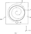
图3从上方观察支撑有基板P的基板载台PST的俯视图。以包围保持于基板载台PST(基板保持具PH)的基板P周围的方式进行基板载台PST的上面97的配置。于基板P的边缘与基板载台PST的上面97间,设有既定的间隙G1。又,于基板P上设定有复数个照射区域SH,控制装置CONT一边监控激光干涉仪94的输出,一边使基板载台PST于XY方向移动,对设定于基板P上的复数个照射区域SH依序曝光。 FIG. 3 is a plan view of the substrate stage PST on which the substrate P is supported viewed from above. The
又,本实施方式中,于基板P形成有为缺口部的定向平面部OF,在与基板载台PST中的上面97连接的内侧面形成有对应定向平面部OF形状的平面部。又,于定向平面部OF与上面97之间也形成既定间隙G2。此外,当于基板P形成有凹槽部作为缺口部时,在连接基板载台PST的上面97的凹部96内侧面形成对应凹槽部形状的突起部。此外,当凹槽部的大小小到足以抑制液体LQ渗入间隙G1时,亦可不在凹部96内侧面设置突起部。 Also, in the present embodiment, the orientation flat portion OF is formed as a notch on the substrate P, and a flat portion corresponding to the shape of the orientation flat portion OF is formed on the inner surface connected to the
其次,参照图4的流程图说明使用上述曝光装置将基板P曝光的步骤。 Next, the procedure of exposing the board|substrate P using the said exposure apparatus is demonstrated with reference to the flowchart of FIG. 4. FIG. the
在将待曝光处理的基板P装载于基板载台PST后,控制装置CONT即驱动基板载台驱动装置PSTD,使投影光学系统PL与基板P对向。接着,控制装置CONT开始将液体LQ充满投影光学系统PL与基板P间的光路空间K1的动作(步骤SA1)。具体而言,控制装置CONT在使投影光学系统PL与基板P对向的状态下,使用液浸机构100的液体供应机构10开始对投影光学系统PL与基板P间供应液体LQ。 After loading the substrate P to be exposed on the substrate stage PST, the control device CONT drives the substrate stage driving device PSTD so that the projection optical system PL faces the substrate P. Next, the control device CONT starts the operation of filling the optical path space K1 between the projection optical system PL and the substrate P with the liquid LQ (step SA1 ). Specifically, the control device CONT starts supplying the liquid LQ between the projection optical system PL and the substrate P using the liquid supply mechanism 10 of the liquid immersion mechanism 100 in a state where the projection optical system PL and the substrate P are facing each other. the
此处,以下说明中,为了以液体LQ充满光路空间K1、而使用液浸机构100的液体供应机构10及液体回收机构20进行液体LQ的供应及回收的动作,称为“液体充满动作”。 Here, in the following description, the operation of supplying and recovering the liquid LQ using the liquid supply mechanism 10 and the liquid recovery mechanism 20 of the liquid immersion mechanism 100 in order to fill the optical path space K1 with the liquid LQ is referred to as "liquid filling operation". the
步骤SA1中,在开始液体充满动作后,控制装置CONT将使用液浸机构100的液体供应机构10及液体回收机构20的液体充满动作持续既定时间(步骤SA2)。控制装置CONT通过持续液体充满动作既定时间使液体LQ充满光路空间K1。控制装置CONT在光路空间K1被液体LQ充满且形成所欲状态(大小)的液浸区域LR的时间点,即判断液体充满动作结束(步骤SA3)。 In step SA1, after starting the liquid filling operation, the control device CONT continues the liquid filling operation of the liquid supply mechanism 10 and the liquid recovery mechanism 20 using the liquid immersion mechanism 100 for a predetermined time (step SA2). The control device CONT fills the optical path space K1 with the liquid LQ by continuing the liquid filling operation for a predetermined time. The control device CONT judges that the liquid filling operation is completed when the optical path space K1 is filled with the liquid LQ and a liquid immersion region LR of a desired state (size) is formed (step SA3). the
如参照图2的说明,本实施方式中,由于在第一光学元件LS1的下面LSA及嘴构件70的下面70A设有能检测出液浸区域LR状态(大小)的第1~第4传感器31~34,因此控制装置CONT能根据第1~第4传感器31~34的检测结果,检测出液体充满动作的进行状况,预测到光路空间K1被液体LQ充满为止的时间(液体充满动作完成的时间),并能判断液体充满动作是否已结束。 As described with reference to FIG. 2 , in this embodiment, the first to
此处,以下的说明中,将光路空间K1被液体LQ充满的状态称为“湿润状态”。 Here, in the following description, the state in which the optical path space K1 is filled with the liquid LQ is referred to as a "wet state". the
此外,虽在使投影光学系统PL与基板P对向的状态下进行液体充满动作,但也可在使投影光学系统PL与基板载台PST的上面97对向的状态下进行液体充满动作。此时,只要在将液体充满于投影光学系统PL与基板载台PST的上面97之间后,将液体LQ保持于投影光学系统PL的下面LSA侧的状态下,使基板载台PST于XY方向移动,将液体LQ的液浸区域LR移动至基板P上即可。 In addition, although the liquid filling operation is performed with the projection optical system PL facing the substrate P, the liquid filling operation may be performed with the projection optical system PL facing the
在投影光学系统PL与基板P(与该投影光学系统PL对向)间的光路空间K1被液体LQ充满后,控制装置CONT从照明光学系统IL射出曝光用光EL,以曝光用光EL照射保持于掩膜载台MST的掩膜M。通过掩膜M的曝光用光EL透过投影光学系统PL及光路空间K1的液体LQ照射于基板P。藉此来对基板P进行液浸曝光(步骤SA4)。 After the optical path space K1 between the projection optical system PL and the substrate P (opposite to the projection optical system PL) is filled with the liquid LQ, the control device CONT emits the exposure light EL from the illumination optical system IL, and irradiates and maintains it with the exposure light EL. Mask M on mask stage MST. The exposure light EL passed through the mask M is irradiated onto the substrate P through the projection optical system PL and the liquid LQ in the optical path space K1. Thereby, liquid immersion exposure is performed on the board|substrate P (step SA4). the
对基板P的液浸曝光结束后,控制装置CONT停止液体供应机构10的液体 LQ的供应动作,且使用液体回收机构20开始回收光路空间K1的液体LQ的动作(步骤SA5)。亦即,本实施方式在每次对基板P的液浸曝光结束时,回收所有光路空间K1的液体LQ。 After the liquid immersion exposure to the substrate P is completed, the control device CONT stops the supply operation of the liquid LQ of the liquid supply mechanism 10, and uses the liquid recovery mechanism 20 to start the operation of recovering the liquid LQ in the optical path space K1 (step SA5). That is, in this embodiment, every time the liquid immersion exposure to the substrate P is completed, the liquid LQ in the entire optical path space K1 is recovered. the
此处,以下说明中,将液浸曝光完成后使用液体回收机构20回收光路空间K1的液体LQ的动作称为“液体回收动作”。 Here, in the following description, the operation of recovering the liquid LQ in the optical path space K1 by using the liquid recovery mechanism 20 after liquid immersion exposure is referred to as "liquid recovery operation". the
步骤SA4中,在开始液体回收动作后,控制装置CONT持续使用液浸机构100的液体回收机构20的液体回收动作既定时间(步骤SA6)。控制装置CONT通过持续液体回收动作既定时间而能大致全部回收光路空间K1的液体LQ。控制装置CONT大致全部回收光路空间K1的液体LQ的时间点,控制装置CONT判断液体回收动作已结束(步骤SA7)。液体回收动作结束后,光路空间K1为无液体LQ的状态。 In step SA4, after starting the liquid recovery operation, the control device CONT continues the liquid recovery operation using the liquid recovery mechanism 20 of the liquid immersion mechanism 100 for a predetermined time (step SA6). The control device CONT can recover almost all of the liquid LQ in the optical path space K1 by continuing the liquid recovery operation for a predetermined time. When the control device CONT recovers almost all the liquid LQ in the optical path space K1, the control device CONT judges that the liquid recovery operation has ended (step SA7). After the liquid recovery operation is completed, the optical path space K1 is in a state without the liquid LQ. the
与液体充满动作相同,在进行液体回收动作时,控制装置CONT也能根据第一传感器31~第四传感器34的检测结果,检测液体回收动作的进行状态,求出从光路空间K1到回收液体LQ为止的时间(到液体回收动作结束为止的时间),以判断液体回收动作是否结束。 Similar to the liquid filling operation, during the liquid recovery operation, the control device CONT can also detect the progress state of the liquid recovery operation based on the detection results of the
此处,在以下说明中,将光路空间K1无液体LQ的状态称为“干燥状态”。 Here, in the following description, the state in which the optical path space K1 is free from the liquid LQ is referred to as a "dry state". the
在液体回收动作结束后,基板P上或基板载台PST上可能残留液体LQ。因此,控制装置CONT一边使基板载台PST相对嘴构件70的回收口22移动,一边透过回收口22吸引回收残留于基板P上或基板载台PST上的液体LQ,藉此开始去除动作(步骤SA8)。 After the liquid recovery operation is completed, the liquid LQ may remain on the substrate P or the substrate stage PST. Therefore, the control device CONT moves the substrate stage PST relative to the
此处,以下说明中,将液体回收动作结束后、使用液体回收机构20来去除残留于基板P上或基板载台PST上的液体LQ的动作称为“液体去除动作”。 Here, in the following description, the operation of using the liquid recovery mechanism 20 to remove the liquid LQ remaining on the substrate P or the substrate stage PST after the liquid recovery operation is completed is referred to as a "liquid removal operation". the
图5所示为进行基板P上及基板载台PST上的液体去除动作的示意图。控制装置CONT一边监控激光干涉仪94的输出一边移动基板载台PST,使液体回收机构20的回收口22与基板P沿图5的虚线箭头y1相对移动。通过基板载台PST的沿XY平面的并进移动,使回收口22扫描基板P及基板载台PST上面的 大致全区域。藉此,液体回收机构20通过回收口22将残留于基板P及基板载台PST上的液体LQ吸走,确实地加以去除残留于基板P及基板载台PST上的液体LQ。 FIG. 5 is a schematic diagram showing a liquid removal operation performed on the substrate P and the substrate stage PST. The control device CONT moves the substrate stage PST while monitoring the output of the laser interferometer 94, and relatively moves the
此外,图5所示的例中,基板P及基板载台PST描绘出反复相对回收口往X轴方向的扫描移动与往Y轴方向的步进移动的移动轨迹,但该移动轨迹亦可任意设定,例如亦可如图6的虚线箭头y2所示,以从基板P外侧向内侧(或从内侧朝外侧)描绘圆的螺旋状移动轨迹的方式移动,或亦可沿同心状描绘出复数个大小圆轨迹的方式移动。 In addition, in the example shown in FIG. 5, the substrate P and the substrate stage PST describe a moving trajectory that repeats scanning movement in the X-axis direction and stepping movement in the Y-axis direction relative to the recovery port, but the movement trajectory can also be arbitrary. Setting, for example, as shown by the dotted line arrow y2 in FIG. 6, it may be moved in a manner that draws a circular spiral trajectory from the outside to the inside (or from the inside to the outside) of the substrate P, or may also draw a plurality of concentric shapes. Move in the form of a large and small circular trajectory. the
或是,亦可如图7的虚线箭头y3所示,以回收口22在基板载台PST上描绘出沿基板P边缘与基板载台PST的上面97间的间隙G1的移动轨迹的方式,一边移动基板载台PST一边透过回收口22进行液体去除动作。又,控制装置CONT也可将基板P的定位平面部OF与液体回收机构20回收口22配置成对向,重点式地进行间隙G2附近的液体去除动作。 Alternatively, as shown by the dotted arrow y3 in FIG. 7 , the
如此,控制装置CONT即一边移动基板载台PST,一边持续液体回收机构20的液体去除动作既定时间(步骤SA9)。控制装置CONT可通过持续液体去除动作既定时间将残留于基板P上及基板载台PST上的液体LQ大致全部去除。控制装置CONT在去除残留于基板P上及基板载台PST上的液体LQ的时间点,判断液体去除动作已结束(步骤SA10)。通过液体去除动作的结束,除了光路空间K1以外、于基板P上及基板载台PST上均为无液体LQ。在液体去除动作结束后,即将曝光处理结束的基板P从基板载台PST卸载。 In this way, the control device CONT continues the liquid removal operation of the liquid recovery mechanism 20 for a predetermined time while moving the substrate stage PST (step SA9 ). The control device CONT can remove almost all of the liquid LQ remaining on the substrate P and the substrate stage PST by continuing the liquid removal operation for a predetermined time. The control device CONT judges that the liquid removal operation has been completed when the liquid LQ remaining on the substrate P and the substrate stage PST is removed (step SA10 ). By the end of the liquid removal operation, the liquid LQ is free on the substrate P and the substrate stage PST except for the optical path space K1. After the liquid removal operation is completed, the substrate P on which the exposure process has been completed is unloaded from the substrate stage PST. the
上述的液体回收动作(步骤SA5~SA7)大致以维持嘴构件70与基板载台PST的相对位置关系的状态来进行。亦即,液体回收动作为基板载台PST与嘴构件70相对为静止的状态下从液体回收机构20的回收口22吸引回收液体LQ的动作,其动作在短时间结束。另一方面,液体去除动作(步骤SA8~SA10)一边使嘴构件70与基板载台PST相对移动一边进行。即液体去除动作一边使基板载台PST相对嘴构件70移动一边使用液体回收机构20的回收口22去除液体 LQ的动作,其较液体回收动作花费更长时间。 The above-mentioned liquid recovery operation (steps SA5 to SA7 ) is generally performed while maintaining the relative positional relationship between the
其次,说明上述步骤SA1~SA10的处理中的显示装置D的动作(显示内容)。此外,以下说明中,显示装置D根据控制装置CONT的指令来进行显示。 Next, the operation (display content) of the display device D in the processing of steps SA1 to SA10 described above will be described. In addition, in the following description, the display device D performs display according to an instruction from the control device CONT. the
本实施方式的显示装置D具有与曝光装置EX状态及动作(包含曝光装置EX所进行的处理内容)相关的信息、或显示装置D显示与曝光处理相关的各种信息的功能。具体而言,显示装置D具有用以显示液浸机构100以液体LQ充满曝光用光EL的光路空间K1时的进行状况、以及从光路空间K1去除液体LQ时的进行状况的功能。又,显示装置D亦具有用以显示与曝光装置EX的状态(动作)相关的信息(包含过去进行的处理内容)或包含各种测量装置的测量结果的信息(记录信息)的功能。 The display device D in this embodiment has information related to the state and operation of the exposure device EX (including processing contents performed by the exposure device EX), or a function of the display device D to display various information related to exposure processing. Specifically, the display device D has a function of displaying the progress of the liquid immersion mechanism 100 filling the optical path space K1 of the exposure light EL with the liquid LQ and the progress of removing the liquid LQ from the optical path space K1. In addition, the display device D also has a function of displaying information (including processing contents performed in the past) related to the state (operation) of the exposure device EX or information (record information) including measurement results of various measuring devices. the
又,显示装置D也具有显示液浸区域LR状态的功能、显示基板P状态的功能、显示关于基板P的信息(关于所使用光阻的信息、批量信息等)的功能、以及显示曝光条件(扫描速度、曝光用光的照射量等)的功能等。又,显示装置D也具有作为用以操作曝光装置EX的操作部的功能。具体而言,本实施方式的显示装置D在显示画面上具备各种按钮(图标),操作者等能通过使用鼠标或键盘等操作输入部操作按钮,来对曝光装置进行操作输入。又,显示装置D为触控面板时,操作者等可通过触控显示装置D画面上的既定位置来对曝光装置EX进行操作输入。 Moreover, the display device D also has a function of displaying the state of the liquid immersion region LR, a function of displaying the state of the substrate P, a function of displaying information about the substrate P (information about the photoresist used, batch information, etc.), and displaying exposure conditions ( Scanning speed, irradiation amount of exposure light, etc.) functions, etc. In addition, the display device D also has a function as an operation unit for operating the exposure device EX. Specifically, the display device D of the present embodiment includes various buttons (icons) on the display screen, and an operator can perform operation input to the exposure device by operating the buttons using an operation input unit such as a mouse or a keyboard. Moreover, when the display device D is a touch panel, an operator etc. can perform operation input to the exposure device EX by touching a predetermined position on the screen of the display device D. the
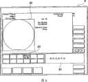
图8为表示上述的步骤SA1,亦即液体充满动作开始时的显示装置D的显示内容例的示意图。显示装置D能显示曝光装置EX所进行的处理内容(包含液体充满动作、液体回收动作、及液体去除动作等)的进行状态,在显示画面的第一区域D1,以“液体充满开始”的文字来显示充满动作已开始。又,于显示装置D的显示画面的第二区域D2,是通过影像来显示基板P的状态。又,在显示装置D的显示画面的第三区域D3,通过文字显示有嘴构件70的状态。 FIG. 8 is a schematic diagram showing an example of display contents of the display device D when the above-mentioned step SA1, that is, when the liquid filling operation starts. The display device D can display the progress status of the processing content (including liquid filling operation, liquid recovery operation, and liquid removal operation, etc.) performed by the exposure device EX. In the first area D1 of the display screen, the words "liquid filling starts" to show that the filling action has started. In addition, in the second area D2 of the display screen of the display device D, the state of the board|substrate P is displayed by an image. Moreover, in the third area D3 of the display screen of the display device D, the state of the
图9所示为上述步骤SA2中液体充满动作中的显示装置D的显示内容一例的图。如图9所示,在显示装置D的显示画面上显示“液体充满动作中”显示 液体充满动作的进行状况。为了显示液体充满动作中的进行状态,于显示装置D的显示画面的第四区域D4显示有窗口,窗口以文字、数字、以及图(渐进条)来显示进行状况。虽从液体充满动作开始到结束为止需要既定时间,但本实施方式的显示装置D以文字、数字、及图(渐进条)来显示到液体充满动作结束为止的时间。又,在液体充满动作开始后,由于嘴构件70从干燥状态转变成湿润状态;因此,为了显示该嘴构件70的状态而变更第三区域D3的显示内容。 FIG. 9 is a diagram showing an example of display contents of the display device D during the liquid filling operation in the above step SA2. As shown in Figure 9, on the display screen of display device D, display " in the liquid is filled with action " and display the progress situation of liquid is filled with action. In order to display the progress status of the liquid filling operation, a window is displayed in the fourth area D4 of the display screen of the display device D, and the window displays the progress status with letters, numbers, and graphs (progressive bars). Although a predetermined time is required from the start to the end of the liquid filling operation, the display device D of this embodiment displays the time until the liquid filling operation is completed using letters, numbers, and graphs (progressive bars). Also, since the
图10是显示上述步骤SA3结束亦即液体充满动作结束时显示装置D的显示内容例的图。此处,在液体充满动作结束时,显示装置D显示光路空间K1已由液体LQ充满的状态(湿润状态)。显示装置D显示画面的第1区域D1以“湿润状态”的文字来显示光路空间K1已由液体LQ充满的状态。 FIG. 10 is a diagram showing an example of the display content of the display device D when the above-mentioned step SA3 is completed, that is, the liquid filling operation is completed. Here, at the end of the liquid filling operation, the display device D displays the state (wet state) in which the optical path space K1 is filled with the liquid LQ. The first area D1 of the display screen of the display device D displays the state in which the optical path space K1 is filled with the liquid LQ in the characters "wet state". the
图11是显示上述步骤SA4中,即液体曝光中的显示装置D显示内容一例的图。如图11所示,显示装置D的显示画面的第一区域D1以“液浸曝光中”的文字来显示液浸曝光中的状态。又,显示装置D显示画面的第二区域D2以影像来显示基板P的状态,复数个照射区域SH中曝光已结束的照射区域、与曝光尚未结束的照射区域系以不同方式来显示。 FIG. 11 is a diagram showing an example of display contents of the display device D in the above-mentioned step SA4, that is, during liquid exposure. As shown in FIG. 11 , in the first region D1 of the display screen of the display device D, the state of the liquid immersion exposure is displayed by the characters "Liquid immersion exposure in progress". In addition, the second area D2 of the display screen of the display device D displays the state of the substrate P as an image, and among the plurality of shot areas SH, the shot area whose exposure has been completed is displayed differently from the shot area where the exposure has not been completed. the
图12是显示上述步骤SA5,亦即液体回收动作开始时显示装置D的显示内容例的图。如图12所示,于显示装置D显示画面的第一区域D1,以“液体回收开始”的文字来显示液体回收动作开始的状态。又,由于嘴构件70的状态会随着液体回收动作开始而改变,因此也改变显示嘴构件状态的第三区域D3的显示内容。 FIG. 12 is a diagram showing an example of the display content of the display device D at the start of the above step SA5, that is, the liquid recovery operation. As shown in FIG. 12 , in the first area D1 of the display screen of the display device D, the state of the start of the liquid recovery operation is displayed with the words "Liquid Recovery Start". Also, since the state of the
图13是显示上述步骤SA6,即液体回收动作中的显示装置D显示内容一例的图。如图13所示,显示装置D的显示画面显示的是液体回收动作中来作为液体动作的进行状况。为了显示液体回收动作中的进行状态,于显示装置D的显示画面的第四区域D4显示窗口,以文字、数字、及图(渐进条)显示来其进行状态。又,液体回收动作开始后,因嘴构件70从湿润状态转变成干燥状态,因此亦改变显示嘴构件状态的第三区域D3的显示内容。此外,如上所述,液体回收 动作从开始到完成的时间较短,因此亦可省略图13所示的渐进条(progressive bar)等的显示。 FIG. 13 is a diagram showing an example of the display content of the display device D during the above step SA6, that is, the liquid recovery operation. As shown in FIG. 13 , the display screen of the display device D displays the progress status of the liquid recovery operation as the liquid operation. In order to display the progress status of the liquid recovery operation, a window is displayed in the fourth region D4 of the display screen of the display device D, and the progress status is displayed by characters, numbers, and graphs (progressive bars). Moreover, after the liquid recovery operation starts, since the
图13是显示上述步骤SA7,亦即液体回收动作结束时显示装置D的显示内容例的图。如图14所示,于显示装置D显示画面的第一区域D1,是以“液体回收完成”的文字来显示液体回收动作结束的状态。又,显示装置D在液体回收动作结束时,即显示于光路空间K1中无液体LQ的状态(干燥状态)。图14中,于显示装置D显示画面的第1区域D1,以“干燥状态”的文字来显示光路空间K1中无液体LQ的状态。 FIG. 13 is a diagram showing an example of the display content of the display device D when the above-mentioned step SA7, that is, when the liquid recovery operation is completed. As shown in FIG. 14 , in the first area D1 of the display screen of the display device D, the words "liquid recovery complete" are used to indicate the status of the completion of the liquid recovery operation. In addition, the display device D displays the state (dry state) in which there is no liquid LQ in the optical path space K1 when the liquid recovery operation is completed. In FIG. 14 , in the first area D1 of the display screen of the display device D, the state of no liquid LQ in the optical path space K1 is displayed with the characters "dry state". the
图15是显示上述步骤SA8,即液体去除开始时显示装置D的显示内容例的图。如图15所示,于显示装置D显示画面的第一区域D1,以“液体去除开始”的文字来显示液体去除动作开始的状态。 FIG. 15 is a diagram showing an example of the display content of the display device D at the time of the above-mentioned step SA8, that is, when liquid removal is started. As shown in FIG. 15 , in the first area D1 of the display screen of the display device D, the state of the start of the liquid removal operation is displayed with the words "Liquid Removal Start". the
图16是显示上述步骤SA9,即液体去除动作中显示装置D的显示内容例的图。如图16所示,显示装置D的显示画面显示液体去除动作中来作为液体去除动作的进行状况。为了显示液体去除动作中的进行状况,于显示装置D的显示画面的第四区域D4显示窗口,以文字、数字、及图(渐进条)显示其进行状态。又,液体去除动作开始后,为了显示嘴构件70进行液体去除动作的状态,改变第3区域D3的显示内容。 FIG. 16 is a diagram showing an example of the display content of the display device D during the above step SA9, that is, the liquid removal operation. As shown in FIG. 16 , the display screen of the display device D displays that the liquid removal operation is in progress as the progress status of the liquid removal operation. In order to display the progress status of the liquid removal operation, a window is displayed in the fourth area D4 of the display screen of the display device D, and the progress status is displayed by characters, numbers, and graphs (progressive bars). Moreover, after the liquid removal operation starts, the display content of the third area D3 is changed in order to display the state of the
图17显示上述步骤SA10,即液体去除完成时显示装置D的显示内容例的图。如图17所示,于显示装置D显示画面的第一区域D1,以“液体去除动作完成”的文字来显示液体去除动作结束的状况。又,显示装置D在液体去除动作结束时,以“干燥状态”的文字来显示于光路空间K1中无液体LQ的状态(干燥状态)。又,改变第三区域D3的显示内容,以显示嘴构件70为液体去除动作的状态。 FIG. 17 is a diagram showing an example of the display content of the display device D when the above step SA10, that is, liquid removal is completed. As shown in FIG. 17 , in the first area D1 of the display screen of the display device D, the status of the completion of the liquid removal operation is displayed with the words "liquid removal operation completed". Furthermore, the display device D displays the state (dry state) in which there is no liquid LQ in the optical path space K1 in the characters "dry state" at the end of the liquid removal operation. In addition, the display content of the third area D3 is changed so as to indicate that the
又,如图18所示,显示装置D能显示曝光装置EX产生错误等时的状态。图18所示的例中,是显示当产生错误等、不知于光路空间K1是否有液体LQ时的显示内容的一例。 In addition, as shown in FIG. 18, the display device D can display the state when an error or the like occurs in the exposure device EX. The example shown in FIG. 18 is an example of display content when it is not known whether or not there is liquid LQ in the optical path space K1 due to an error or the like. the
如以上说明,藉由显示装置D的显示,操作者等能掌握以液体LQ充满曝光用光EL的光路空间K1时的进行状况、以及从光路空间K1去除液体LQ时的进行状况。据此,在液体充满动作中、液体回收动作中、或液体去除动作中,例如当操作者移动与投影光学系统PL对向的基板P或基板载台PST而使其从投影光学系统PL的正下方退离时,即使产生液体LQ的流出、飞散等,但利用显示装置D的显示由于即能掌握液体充满动作、液体回收动作、或液体去除动作的进行状况,因此能防止上述液体LQ的流出、飞散。据此,能防止因流出、飞散的液体LQ所造成的设有曝光装置EX的环境变动或构成曝光装置EX的各种机器构件生锈或故障等产生,能使用曝光装置EX以良好精度使基板P曝光。 As described above, through the display of the display device D, the operator can grasp the progress of filling the optical path space K1 of the exposure light EL with the liquid LQ and the progress of removing the liquid LQ from the optical path space K1. Accordingly, during the liquid filling operation, the liquid recovery operation, or the liquid removal operation, for example, when the operator moves the substrate P or the substrate stage PST facing the projection optical system PL from the front of the projection optical system PL, Even if the liquid LQ flows out or scatteres when the bottom moves away, the display of the display device D can be used to grasp the progress of the liquid filling operation, liquid recovery operation, or liquid removal operation, so the above-mentioned outflow of the liquid LQ can be prevented. , flying away. Accordingly, it is possible to prevent changes in the environment in which the exposure device EX is installed due to the outflowing and scattering liquid LQ, or rusting or failure of various machine components constituting the exposure device EX, and it is possible to use the exposure device EX to expose the substrate with high precision. P exposure. the
此外,上述实施方式中,显示装置D能分别显示液体LQ充满曝光用光EL的光路空间K1时的进行状况、及从光路空间K1去除液体LQ时的进行状况,但亦可仅显示任意一个的进行状况。 In addition, in the above-mentioned embodiment, the display device D can display the progress status when the liquid LQ fills the optical path space K1 of the exposure light EL and the progress status when the liquid LQ is removed from the optical path space K1, but only one of them may be displayed. progress status. the
此外,于上述实施方式中,虽使用第一传感器31~第四传感器34检测液体充满动作的进行状况及液体回收动作的进行状况,并根据其结果来进行显示装置D的显示,但也可不配置上述的传感器,例如利用实验或仿真等,预先求出开始液体充满动作到以液体LQ充满光路空间K1为止的时间,将与该求出的时间相关的信息储存于控制装置CONT,再根据该储存信息掌握液体充满动作的进行状况、或求出液体充满动作结束为止的时间、或于显示装置D显示进行状况,以判断液体充满动作是否结束。液体回收动作同样可根据与储存的时间相关的信息求出液体回收动作完成为止的时间、或于显示装置显示进行状况以判断液体回收动作是否结束。 In addition, in the above-mentioned embodiment, although the
又,上述实施方式中,虽在液体回收动作完成后进行液体去除动作,但亦可于液体LQ的残留较少时或可容许液体LQ的残留时,省略液体去除动作(步骤SA8~SA10)。 Also, in the above embodiment, the liquid removal operation is performed after the liquid recovery operation is completed, but the liquid removal operation (steps SA8 to SA10 ) may be omitted when the liquid LQ remains little or the liquid LQ remains tolerably. the
又,亦可于显示装置D显示画面中的第二区域D2,除了显示液浸区域LR以外亦显示基板P与液浸区域LR的位置关系。 In addition, the display device D may display the positional relationship between the substrate P and the liquid immersion region LR in addition to the liquid immersion region LR in the second region D2 on the display screen. the
如上所述,本实施方式的液体LQ是纯水。纯水的优点为能容易地在半导体制造工厂等处大量取得,且对基板P上的光阻或光学元件(透镜)等无不良影响。又,纯水除了对环境无不良影响外,由于杂质的含有量极低,因此亦能期待有洗净光学元件(设于基板P的表面、以及投影光学系统PL的前端面)的作用。又,从工厂等所供应的纯水纯度较低时,也可使曝光装置具备超纯水制造器。 As mentioned above, the liquid LQ of this embodiment is pure water. The advantage of pure water is that it can be easily obtained in large quantities in semiconductor manufacturing factories and the like, and has no adverse effect on photoresists or optical elements (lenses) on the substrate P. In addition to having no adverse effect on the environment, pure water can also be expected to clean the optical elements (the surface of the substrate P and the front end surface of the projection optical system PL) because the content of impurities is extremely low. Moreover, when the purity of the pure water supplied from a factory etc. is low, you may equip an exposure apparatus with an ultrapure water maker. the
又,纯水(水)对波长为193nm左右的曝光用光EL的折射率n大致为1.44左右,若使用ArF准分子激光(波长193nm)作为曝光用光EL的光源时,则在基板P上将波长缩短为1/n,即大约134nm左右,可获得高分辨率。再者,由于焦深与在空气中相比放大约n倍、即约1.44倍,因此只要能确保与在空气中使用时相同程度的焦深时,即能更增加投影光学系统PL的数值孔径,从此点来看也能提高分辨率。 Also, pure water (water) has a refractive index n of about 1.44 for exposure light EL having a wavelength of about 193 nm. Shorten the wavelength to 1/n, which is about 134nm, to obtain high resolution. Furthermore, since the depth of focus is enlarged by about n times compared to that in air, that is, about 1.44 times, as long as the same level of depth of focus as that used in air can be ensured, the numerical aperture of the projection optical system PL can be further increased. , from this point of view, the resolution can also be improved. the
本实施方式将光学元件LS1安装于投影光学系统PL前端,通过此透镜能进行投影光学系统PL的光学特性的调整,例如像差(球面像差、彗形像差等)。此外,作为安装于投影光学系统PL前端的光学元件,可使用于调整投影光学系统PL的光学特性的光学板。光学元件也可以为使曝光用光EL透射的平行平面板。 In this embodiment, the optical element LS1 is attached to the front end of the projection optical system PL, and the optical characteristics of the projection optical system PL, such as aberrations (spherical aberration, coma, etc.), can be adjusted through this lens. In addition, as an optical element attached to the front end of projection optical system PL, an optical plate for adjusting the optical characteristics of projection optical system PL can be used. The optical element may be a parallel plane plate that transmits the exposure light EL. the
又,上述实施方式的投影光学系统虽以液体充满前端光学元件的像面侧的光路空间,但也可如国际公开号为2004/019128申请说明书所揭示的内容,投影光学系统以液体充满的前端光学元件的掩膜侧的光路空间。此时,能以显示装置D显示掩膜侧的光路空间的液体充满动作进行状况与液体回收动作进行状况的至少一方。 In addition, although the projection optical system of the above-mentioned embodiment fills the optical path space on the image plane side of the front optical element with liquid, it can also be used to fill the front end of the projection optical system with liquid as disclosed in the application specification of International Publication No. 2004/019128. The optical path space on the mask side of the optical element. At this time, at least one of the progress status of the liquid filling operation and the progress status of the liquid recovery operation in the optical path space on the mask side can be displayed on the display device D. the
此外,本实施方式的液体虽为水,但亦可是水以外的液体。例如,曝光用光的光源为F2激光时,由于此F2激光无法透射水,因此亦可使用能使F2激光透射的液体来作为液体LQ,例如全氟聚醚(PFPE,perfluoro-polyether)或氟系油等氟系流体亦可。此时,例如以包含氟的极性小的分子构造物质来形成薄膜,藉此对与液体LQ接触的部分进行亲液化处理。又,液体LQ可以是其它能使曝光用光EL具透射性且折射率尽可能较高、并对涂布于投影光学系统PL或基板P 表面的光阻较稳定的液体LQ(例如杉木油(cedar oil))。此时,表面处理亦根据所使用的液体LQ的极性来进行。 In addition, although the liquid of this embodiment is water, it may be liquids other than water. For example, when the light source of the exposure light is F2 laser, since the F2 laser cannot transmit water, a liquid that can transmit F2 laser can also be used as the liquid LQ, such as perfluoropolyether (PFPE, perfluoro-polyether) or fluorine. Fluorine-based fluids such as oils are also acceptable. At this time, for example, a thin film is formed of a low-polarity molecular structure substance containing fluorine, thereby performing a lyophilic treatment on a portion in contact with the liquid LQ. Also, the liquid LQ can be other liquid LQ that can make the exposure light EL transmissive and has a high refractive index as much as possible, and is relatively stable to the photoresist coated on the surface of the projection optical system PL or the substrate P (such as fir oil ( cedar oil)). At this time, the surface treatment is also performed according to the polarity of the liquid LQ used. the
又,作为上述各实施方式的基板P除了半导体元件制造用的半导体晶片以外,也能适用于显示器元件用的玻璃基板、薄膜磁头用的陶瓷晶片、或在曝光装置所使用的掩膜或标线片的原版(合成石英、硅晶片)等。 In addition, as the substrate P of each of the above-mentioned embodiments, in addition to semiconductor wafers for semiconductor element manufacturing, glass substrates for display elements, ceramic wafers for thin-film magnetic heads, or masks or reticles used in exposure devices can also be applied. The original version of the chip (synthetic quartz, silicon wafer), etc. the
作为曝光装置EX,除了能适用于使掩膜M与基板P同步移动来对掩膜M的图案进行扫描曝光的步进扫描方式的扫描型曝光装置(扫描步进机)以外,也能适用于步进重复方式的投影曝光装置(步进器)。步进重复方式的投影曝光装置在使掩膜M与基板P静止的状态下,使掩膜M的图案一次曝光,并使基板P依序步进移动。 As the exposure apparatus EX, in addition to being applicable to a scanning exposure apparatus (scanning stepper) of a step-and-scan method in which the mask M and the substrate P are moved synchronously to scan and expose the pattern of the mask M, it can also be applied to A step-and-repeat projection exposure device (stepper). The projection exposure apparatus of the step-and-repeat method exposes the pattern of the mask M once while keeping the mask M and the substrate P stationary, and moves the substrate P sequentially in steps. the
又,本发明适用于揭示在特开平10-163099号公报、特开平10-214783号公报、特表2000-505958号公报的双载台型曝光装置。 Also, the present invention is applicable to the double-stage exposure apparatuses disclosed in JP-A-10-163099, JP-A-10-214783, and JP-A-2000-505958. the
又,本发明适用于例如具有特开平11-135400号公报揭示的基板载台与测量载台的曝光装置。此时,投影光学系统PL可采取与测量载台对向的状态,进行上述液体充满动作与液体回收动作中的至少一个。 Also, the present invention is applicable to an exposure apparatus including, for example, a substrate stage and a measurement stage disclosed in JP-A-11-135400. At this time, the projection optical system PL may assume a state facing the measurement stage, and perform at least one of the liquid filling operation and the liquid recovery operation described above. the
此外,上述实施方式中虽采用在投影光学系统PL与基板P的间局部充满液体的曝光装置,但本发明,适用于如揭示在特开平6-124873号公报、特开平10-303114号公报、美国专利第5,825,043中将曝光对象的基板表面整体浸于液体中的状态下进行曝光的液浸曝光装置。 In addition, although the exposure apparatus in which the space between the projection optical system PL and the substrate P is partially filled with liquid is used in the above-mentioned embodiments, the present invention is applicable to applications such as those disclosed in JP-A-6-124873, JP-A-10-303114, In US Patent No. 5,825,043, a liquid immersion exposure apparatus is used to expose the entire surface of a substrate to be exposed in a state of being immersed in a liquid. the
作为曝光装置EX的种类,并不限于用以将半导体元件图案曝光于基板P的半导体元件制造用曝光装置,而也能广泛适用于液晶显示元件制造用或显示器制造用的曝光装置、或用以制造薄膜磁头、摄影元件(CCD)、标线片、以及掩膜等的曝光装置等。 The type of exposure apparatus EX is not limited to an exposure apparatus for manufacturing a semiconductor element for exposing a pattern of a semiconductor element on a substrate P, but can be widely used in an exposure apparatus for liquid crystal display element manufacturing or display manufacturing, or for Manufactures thin-film magnetic heads, imaging devices (CCDs), reticles, and exposure devices such as masks. the
本实施方式的曝光装置EX是通过组装各种子系统(包含本案申请范围中所列举的各构成要素),以保持既定的机械精度、电气精度、光学精度的方式制造。为确保上述各种精度,在组装前后对各种光学系统进行光学精度的调整、对各 种机械系统进行机械精度的调整、对各种电气系统进行电气精度的调整。从各种次系统至曝光装置的组装工艺包含各种次系统相互的机械连接、电路的配线连接、气压回路的配管连接等。当然,从各种次系统至曝光装置的组装工艺前有各次系统个别的组装工艺。当各种次系统至曝光装置的组装工艺结束后,即进行综合调整,以确保曝光装置整体的各种精度。此外,曝光装置的制造最好是在温度及清洁度等都受到管理的洁净室进行。 The exposure apparatus EX of this embodiment is manufactured by assembling various subsystems (including each component listed in the scope of the present application) so as to maintain predetermined mechanical precision, electrical precision, and optical precision. In order to ensure the above-mentioned precision, the optical precision of various optical systems, the mechanical precision of various mechanical systems, and the electrical precision of various electrical systems are adjusted before and after assembly. The assembly process from various subsystems to exposure equipment includes mutual mechanical connection of various subsystems, wiring connection of electric circuits, piping connection of air pressure circuit, etc. Of course, there are separate assembly processes for each sub-system before the assembly process from various sub-systems to the exposure device. After the assembly process of various subsystems to the exposure device is completed, comprehensive adjustments are performed to ensure various precisions of the exposure device as a whole. In addition, it is preferable to manufacture the exposure device in a clean room where temperature, cleanliness, etc. are controlled. the
半导体元件的微元件,如图19所示,是经由下述步骤所制造,即:进行微元件的功能、性能设计的步骤201、根据此设计步骤制作掩膜(标线片)的步骤202、制造构成元件基材的基板的步骤203、通过前述实施方式的曝光装置EX将掩膜图案曝光于基板的曝光处理步骤204、元件组装步骤(包含切割步骤、接合步骤、封装步骤)205、检查步骤206等。 The micro-element of the semiconductor element, as shown in Figure 19, is manufactured through the following steps, that is: the
Claims (9)
Translated fromChineseApplications Claiming Priority (3)
| Application Number | Priority Date | Filing Date | Title |
|---|---|---|---|
| JP2004353948 | 2004-12-07 | ||
| JP353948/2004 | 2004-12-07 | ||
| PCT/JP2005/022371WO2006062096A1 (en) | 2004-12-07 | 2005-12-06 | Exposure apparatus and method for manufacturing device |
Publications (2)
| Publication Number | Publication Date |
|---|---|
| CN101002303A CN101002303A (en) | 2007-07-18 |
| CN101002303Btrue CN101002303B (en) | 2012-05-23 |
Family
ID=36577923
Family Applications (1)
| Application Number | Title | Priority Date | Filing Date |
|---|---|---|---|
| CN2005800271318AExpired - Fee RelatedCN101002303B (en) | 2004-12-07 | 2005-12-06 | Exposure apparatus and device manufacturing method |
Country Status (8)
| Country | Link |
|---|---|
| US (1) | US20080100811A1 (en) |
| EP (1) | EP1833081A4 (en) |
| JP (1) | JPWO2006062096A1 (en) |
| KR (1) | KR20070100864A (en) |
| CN (1) | CN101002303B (en) |
| IL (1) | IL183628A0 (en) |
| TW (1) | TW200632578A (en) |
| WO (1) | WO2006062096A1 (en) |
Families Citing this family (3)
| Publication number | Priority date | Publication date | Assignee | Title |
|---|---|---|---|---|
| CN103389625A (en)* | 2013-07-11 | 2013-11-13 | 浙江大学 | Communication method of immersion liquid transmission system applied to immersion lithography machine |
| CN104166315B (en)* | 2014-08-14 | 2017-05-17 | 深圳市华星光电技术有限公司 | Exposure method and exposure machine |
| DE102024210061A1 (en)* | 2024-10-17 | 2025-06-18 | Carl Zeiss Smt Gmbh | Object holding device for a lithography mask of projection lithography and substrate holding device for a wafer of projection lithography |
Citations (2)
| Publication number | Priority date | Publication date | Assignee | Title |
|---|---|---|---|---|
| US4796469A (en)* | 1987-03-16 | 1989-01-10 | B-Conn, Inc. | Apparatus and process for measuring change of liquid level in storage tanks |
| US5610683A (en)* | 1992-11-27 | 1997-03-11 | Canon Kabushiki Kaisha | Immersion type projection exposure apparatus |
Family Cites Families (31)
| Publication number | Priority date | Publication date | Assignee | Title |
|---|---|---|---|---|
| US4346164A (en)* | 1980-10-06 | 1982-08-24 | Werner Tabarelli | Photolithographic method for the manufacture of integrated circuits |
| JPS57153433A (en)* | 1981-03-18 | 1982-09-22 | Hitachi Ltd | Manufacturing device for semiconductor |
| US5197118A (en)* | 1985-07-25 | 1993-03-23 | Canon Kabushiki Kaisha | Control system for a fine pattern printing apparatus |
| US5525808A (en)* | 1992-01-23 | 1996-06-11 | Nikon Corporaton | Alignment method and alignment apparatus with a statistic calculation using a plurality of weighted coordinate positions |
| JP3559999B2 (en)* | 1994-07-29 | 2004-09-02 | 株式会社オーク製作所 | An exposure apparatus with a mask alignment mechanism and a method of aligning, exposing, and transporting a work. |
| US5591299A (en)* | 1995-04-28 | 1997-01-07 | Advanced Micro Devices, Inc. | System for providing integrated monitoring, control and diagnostics functions for semiconductor spray process tools |
| JPH08316124A (en)* | 1995-05-19 | 1996-11-29 | Hitachi Ltd | Projection exposure method and exposure apparatus |
| US5740053A (en)* | 1995-07-31 | 1998-04-14 | Tokyo Electron Limited | Method of controlling monitor used in cleaning machine and object processing machine and monitor apparatus |
| US5825043A (en)* | 1996-10-07 | 1998-10-20 | Nikon Precision Inc. | Focusing and tilting adjustment system for lithography aligner, manufacturing apparatus or inspection apparatus |
| DE69735016T2 (en)* | 1996-12-24 | 2006-08-17 | Asml Netherlands B.V. | Lithographic device with two object holders |
| US5953010A (en)* | 1997-08-01 | 1999-09-14 | Sun Microsystems, Inc. | User-friendly iconic message display indicating progress and status of loading and running system program in electronic digital computer |
| US6368884B1 (en)* | 2000-04-13 | 2002-04-09 | Advanced Micro Devices, Inc. | Die-based in-fab process monitoring and analysis system for semiconductor processing |
| JP2003037051A (en)* | 2001-07-25 | 2003-02-07 | Canon Inc | Exposure apparatus, control method therefor, and method for manufacturing semiconductor device |
| JP4117530B2 (en)* | 2002-04-04 | 2008-07-16 | セイコーエプソン株式会社 | Liquid amount determination apparatus, exposure apparatus, and liquid amount determination method |
| CN101470360B (en)* | 2002-11-12 | 2013-07-24 | Asml荷兰有限公司 | Immersion lithographic apparatus and device manufacturing method |
| EP1420299B1 (en)* | 2002-11-12 | 2011-01-05 | ASML Netherlands B.V. | Immersion lithographic apparatus and device manufacturing method |
| JP2004193208A (en)* | 2002-12-09 | 2004-07-08 | Canon Inc | Information processing equipment |
| JP4352874B2 (en)* | 2002-12-10 | 2009-10-28 | 株式会社ニコン | Exposure apparatus and device manufacturing method |
| EP1429190B1 (en)* | 2002-12-10 | 2012-05-09 | Canon Kabushiki Kaisha | Exposure apparatus and method |
| SG107157A1 (en)* | 2002-12-19 | 2004-11-29 | Asml Holding Nv | Liquid flow proximity sensor for use in immersion lithography |
| US7010958B2 (en)* | 2002-12-19 | 2006-03-14 | Asml Holding N.V. | High-resolution gas gauge proximity sensor |
| TWI421906B (en)* | 2003-05-23 | 2014-01-01 | 尼康股份有限公司 | An exposure method, an exposure apparatus, and an element manufacturing method |
| JP2005019616A (en)* | 2003-06-25 | 2005-01-20 | Canon Inc | Immersion exposure equipment |
| US6809794B1 (en)* | 2003-06-27 | 2004-10-26 | Asml Holding N.V. | Immersion photolithography system and method using inverted wafer-projection optics interface |
| JP4492239B2 (en)* | 2003-07-28 | 2010-06-30 | 株式会社ニコン | Exposure apparatus, device manufacturing method, and exposure apparatus control method |
| KR101641011B1 (en)* | 2003-07-28 | 2016-07-19 | 가부시키가이샤 니콘 | Exposure apparatus, device producing method, and exposure apparatus controlling method |
| JP2005159322A (en)* | 2003-10-31 | 2005-06-16 | Nikon Corp | Surface plate, stage apparatus, exposure apparatus and exposure method |
| TWI361450B (en)* | 2003-10-31 | 2012-04-01 | Nikon Corp | Platen, stage device, exposure device and exposure method |
| WO2005081292A1 (en)* | 2004-02-20 | 2005-09-01 | Nikon Corporation | Exposure apparatus, supply method and recovery method, exposure method, and device producing method |
| JP2005259789A (en)* | 2004-03-09 | 2005-09-22 | Nikon Corp | Detection system, exposure apparatus, and device manufacturing method |
| US8169591B2 (en)* | 2004-08-03 | 2012-05-01 | Nikon Corporation | Exposure apparatus, exposure method, and method for producing device |
- 2005
- 2005-12-06JPJP2006546704Apatent/JPWO2006062096A1/ennot_activeWithdrawn
- 2005-12-06CNCN2005800271318Apatent/CN101002303B/ennot_activeExpired - Fee Related
- 2005-12-06WOPCT/JP2005/022371patent/WO2006062096A1/enactiveApplication Filing
- 2005-12-06EPEP05814498Apatent/EP1833081A4/ennot_activeWithdrawn
- 2005-12-06KRKR1020077000953Apatent/KR20070100864A/ennot_activeWithdrawn
- 2005-12-06USUS11/792,231patent/US20080100811A1/ennot_activeAbandoned
- 2005-12-07TWTW094143116Apatent/TW200632578A/enunknown
- 2007
- 2007-06-03ILIL183628Apatent/IL183628A0/enunknown
Patent Citations (2)
| Publication number | Priority date | Publication date | Assignee | Title |
|---|---|---|---|---|
| US4796469A (en)* | 1987-03-16 | 1989-01-10 | B-Conn, Inc. | Apparatus and process for measuring change of liquid level in storage tanks |
| US5610683A (en)* | 1992-11-27 | 1997-03-11 | Canon Kabushiki Kaisha | Immersion type projection exposure apparatus |
Non-Patent Citations (3)
| Title |
|---|
| JP昭63-73628A 1988.04.04 |
| JP特开2003-59803A 2003.02.28 |
| JP特开平6-124873A 1994.05.06 |
Also Published As
| Publication number | Publication date |
|---|---|
| TW200632578A (en) | 2006-09-16 |
| WO2006062096A1 (en) | 2006-06-15 |
| CN101002303A (en) | 2007-07-18 |
| JPWO2006062096A1 (en) | 2008-06-12 |
| US20080100811A1 (en) | 2008-05-01 |
| EP1833081A4 (en) | 2010-11-24 |
| EP1833081A1 (en) | 2007-09-12 |
| IL183628A0 (en) | 2007-09-20 |
| KR20070100864A (en) | 2007-10-12 |
Similar Documents
| Publication | Publication Date | Title |
|---|---|---|
| CN100490068C (en) | Plate member, substrate holding device, exposure device and method, and element manufacturing method | |
| JP5146519B2 (en) | Exposure apparatus and device manufacturing method | |
| CN107422612B (en) | Liquid immersion member, exposure apparatus, liquid immersion exposure method, and device manufacturing method | |
| CN100555568C (en) | Exposure method and exposure device and manufacturing method | |
| JP4488006B2 (en) | Exposure apparatus and device manufacturing method | |
| CN102714141B (en) | Liquid immersion member, exposure device, exposure method and manufacturing method | |
| WO2007004552A1 (en) | Exposure apparatus and method, exposure apparatus maintenance method, and device manufacturing method | |
| JP4517354B2 (en) | Exposure apparatus and device manufacturing method | |
| CN100552881C (en) | Exposure apparatus, exposure method, and device manufacturing method | |
| JP2014503113A (en) | Immersion member and cleaning method | |
| CN100570822C (en) | Exposure apparatus, exposure method, and device manufacturing method | |
| WO2006106851A1 (en) | Exposure apparatus, exposure method, and device production method | |
| WO2012018051A1 (en) | Cleaning method, device production method, cleaning substrate, immersed member, immersion exposure device, and dummy substrate | |
| JP4752320B2 (en) | Substrate holding apparatus and exposure apparatus, substrate holding method, exposure method, and device manufacturing method | |
| CN101002303B (en) | Exposure apparatus and device manufacturing method | |
| JP2011165798A (en) | Aligner, method used by the aligner, method of manufacturing device, program, and recording medium | |
| JP2010040702A (en) | Stage device, exposure system and device manufacturing method | |
| JP2011029326A (en) | Aligner, maintenance method, and method of fabricating device | |
| WO2010082475A1 (en) | Stage equipment, exposure equipment, exposure method and device manufacturing method | |
| HK1112658A (en) | Exposure apparatus and method for manufacturing device | |
| JP2006310587A (en) | Exposure apparatus and device manufacturing method | |
| JP2011014708A (en) | Exposure device, cleaning method and device manufacturing method | |
| JP2011258819A (en) | Plate member, method of using plate member, method of manufacturing device, and method of manufacturing plate member | |
| JP2010016256A (en) | Foreign substance detection method, exposure method, and device manufacturing method | |
| HK1242789A1 (en) | Liquid immersion member and exposure apparatus |
Legal Events
| Date | Code | Title | Description |
|---|---|---|---|
| C06 | Publication | ||
| PB01 | Publication | ||
| C10 | Entry into substantive examination | ||
| SE01 | Entry into force of request for substantive examination | ||
| C14 | Grant of patent or utility model | ||
| GR01 | Patent grant | ||
| CF01 | Termination of patent right due to non-payment of annual fee | Granted publication date:20120523 Termination date:20211206 | |
| CF01 | Termination of patent right due to non-payment of annual fee |