CN101001177A - Single logical network interface for advanced load balancing and troubleshooting functionality - Google Patents
Single logical network interface for advanced load balancing and troubleshooting functionalityDownload PDFInfo
- Publication number
- CN101001177A CN101001177ACNA2006101681782ACN200610168178ACN101001177ACN 101001177 ACN101001177 ACN 101001177ACN A2006101681782 ACNA2006101681782 ACN A2006101681782ACN 200610168178 ACN200610168178 ACN 200610168178ACN 101001177 ACN101001177 ACN 101001177A
- Authority
- CN
- China
- Prior art keywords
- software
- nic
- driver
- coupled
- function driver
- Prior art date
- Legal status (The legal status is an assumption and is not a legal conclusion. Google has not performed a legal analysis and makes no representation as to the accuracy of the status listed.)
- Pending
Links
Images


Classifications
- H—ELECTRICITY
- H04—ELECTRIC COMMUNICATION TECHNIQUE
- H04L—TRANSMISSION OF DIGITAL INFORMATION, e.g. TELEGRAPHIC COMMUNICATION
- H04L47/00—Traffic control in data switching networks
- H04L47/10—Flow control; Congestion control
- H04L47/12—Avoiding congestion; Recovering from congestion
- H04L47/125—Avoiding congestion; Recovering from congestion by balancing the load, e.g. traffic engineering
Landscapes
- Engineering & Computer Science (AREA)
- Computer Networks & Wireless Communication (AREA)
- Signal Processing (AREA)
- Computer And Data Communications (AREA)
- Stored Programmes (AREA)
- Small-Scale Networks (AREA)
- Data Exchanges In Wide-Area Networks (AREA)
Abstract
Description
Translated fromChinese技术领域technical field
本发明的实施例大体涉及计算机联网领域,且更具体而言涉及一种具有高级负载平衡及故障排除功能性的单一逻辑网络接口。Embodiments of the present invention relate generally to the field of computer networking, and more specifically to a single logical network interface with advanced load balancing and troubleshooting functionality.
背景技术Background technique
网络计算装置通常具有两个或两个以上网络接口卡,以增加计算装置的通信带宽而使其超过单一NIC能够提供的带宽。所述复数个NIC通常指“一组”NIC。通常,所述组共享一公共互联网协议(IP)地址,而同时维持组内对于每一NIC的唯一媒体访问控制(MAC)地址。使用此组配置的一个方面为:计算装置与网络中的其他计算装置之间的网络通信量可分布在组中的NIC之间,使得组的总处理量可最大化。此类操作被称为“负载平衡”。使用组配置的另一方面为:网络通信量可从组内的不起作用或不可靠的NIC迁移到组内的起作用或更可靠的NIC。此类操作被称为“故障排除”。在单一实施中的负载平衡与故障排除的组合通常被称为“LBFO”。Network computing devices typically have two or more network interface cards to increase the communication bandwidth of the computing device beyond what a single NIC can provide. The plurality of NICs is often referred to as a "set" of NICs. Typically, the group shares a common Internet Protocol (IP) address while maintaining a unique Media Access Control (MAC) address for each NIC within the group. One aspect of using this group configuration is that network traffic between a computing device and other computing devices in the network can be distributed among the NICs in the group so that the total throughput of the group can be maximized. Such operations are known as "load balancing". Another aspect of using team configurations is that network traffic can be migrated from non-functional or unreliable NICs within the team to functional or more reliable NICs within the team. Such actions are called "troubleshooting". The combination of load balancing and troubleshooting in a single implementation is often referred to as "LBFO".
对于设立并使网络连接在NIC间迁移以优化计算装置的网络通信处理量及可靠性的LBFO实施,LBFO实施可监控NIC级的操作参数,诸如每一NIC上的误码率及经由每一网络连接交换的数据量。典型的LBFO实施将其LBFO软件定位于操作系统中且经由一个或一个以上装置驱动程序向NIC硬件请求NIC级操作参数。所得架构本质上低效,因为其使LBFO决策及管理功能性远离监控操作参数处若干软件级,因此需要软件级之间的大量正在进行的通信。此外,为减少软件级之间所需的通信及/或由于操作系统中的LBFO实施并非对LBFO完全优化,因此在现有技术LBFO实施中的LBFO决策元件可不利用NIC级可用的所有操作参数。因此,常驻于操作系统中的LBFO实施可由于软件级之间的过量软件通信及基于有限的NIC级操作信息的LBFO决策而实施性能较低。For LBFO implementations that set up and migrate network connections between NICs to optimize network traffic throughput and reliability for computing devices, LBFO implementations can monitor NIC-level operating parameters, such as bit error rates on each NIC and across each network The amount of data exchanged by the connection. A typical LBFO implementation locates its LBFO software in the operating system and requests NIC-level operating parameters from the NIC hardware via one or more device drivers. The resulting architecture is inherently inefficient because it moves LBFO decision-making and management functionality several software levels away from monitoring operational parameters, thus requiring extensive ongoing communication between software levels. Furthermore, LBFO decision elements in prior art LBFO implementations may not utilize all operating parameters available at the NIC level in order to reduce the required communication between software levels and/or because LBFO implementations in operating systems are not fully optimized for LBFO. Therefore, LBFO implementations resident in the operating system may have lower implementation performance due to excessive software communication between software levels and LBFO decisions based on limited NIC-level operational information.
此外,为使LBFO实施为可靠的且维持高性能,其配置应经受操作系统或某第三方(诸如用户或应用程序)的改变。典型的LBFO实施将组中的每一NIC暴露给操作系统,从而给予操作系统对NIC的较大程度的控制权,包括重新配置任何NIC的能力。在所述实施中,操作系统可能够改变与NIC组相关联的IP地址或改变特定NIC的安全设定或通信参数。此外,由于NIC暴露给操作系统,其也暴露给第三方,第三方将能够同样地重新配置NIC。举例而言,用户能够错误地禁用或重新配置一可靠的NIC或错误地启用一不可靠的NIC。总的来说,一组NIC经配置以优化一特定LBFO架构。一旦NIC已配置为组而单方面地重新配置NIC会严重破坏优化,进而降低计算装置的网络通信的性能及/或可靠性。Furthermore, for an LBFO implementation to be reliable and maintain high performance, its configuration should withstand changes by the operating system or some third party, such as a user or an application. A typical LBFO implementation exposes each NIC in the team to the operating system, giving the operating system a greater degree of control over the NICs, including the ability to reconfigure any NIC. In such implementations, the operating system may be able to change IP addresses associated with a group of NICs or change security settings or communication parameters for a particular NIC. Furthermore, since the NIC is exposed to the operating system, it is also exposed to third parties who will be able to reconfigure the NIC as well. For example, a user could mistakenly disable or reconfigure a reliable NIC or mistakenly enable an unreliable NIC. In general, a set of NICs is configured to optimize a particular LBFO architecture. Unilaterally reconfiguring NICs once they have been configured into a team can severely disrupt optimization, thereby reducing the performance and/or reliability of network communications for computing devices.
此外,对于在现代网络中最有用的LBFO实施而言,实施应考虑到网络中可能在使用的附加的安全特性。所述安全特性中的一种为电气与电子工程师协会(IEEE)安全凭证协议(下文称为“802.1X”),其通过在NIC可与交换器通信之前要求NIC向安全凭证服务器请求验证而改进网络安全性。另一安全特性为IEEE“虚拟LAN”协议(下文称为“802.1Q),其也可通过允许网络管理员配置一系列的IP地址作为虚拟LAN(VLAN)且选择性地分配机器到VLAN,进而启用VLAN中机器间的通信且防止VLAN内与VLAN外的机器之间的通信,而改进网络安全性。这些协议中的每一协议均对LBFO实施强加了附加限制。因此,现有LBFO实施的一个缺点为:其并不总在上述安全(802.1X及802.1Q)协议的限制内实施LBFO。Furthermore, for LBFO implementations to be most useful in modern networks, the implementation should take into account additional security features that may be in use in the network. One of these security features is the Institute of Electrical and Electronics Engineers (IEEE) Secure Credentials Protocol (hereinafter "802.1X"), which improves upon by requiring the NIC to request authentication from a secure credential server before it can communicate with the switch network security. Another security feature is the IEEE "Virtual LAN" protocol (hereinafter referred to as "802.1Q), which can also be used by allowing network administrators to configure a series of IP addresses as virtual LANs (VLANs) and selectively assign machines to VLANs. Enabling communication between machines in a VLAN and preventing communication between machines in the VLAN and outside the VLAN improves network security. Each of these protocols imposes additional restrictions on LBFO implementations. Therefore, existing LBFO implementations One disadvantage is that it does not always implement LBFO within the constraints of the above mentioned security (802.1X and 802.1Q) protocols.
如上所述,此项技术中所需的是一种解决上述现有LBFO实施的缺点中的一个或一个以上缺点的LBFO架构。As noted above, what is needed in the art is an LBFO architecture that addresses one or more of the shortcomings of existing LBFO implementations described above.
发明内容Contents of the invention
本发明的一实施例陈述一种用于配置一计算装置的方法,所述计算装置具有一操作系统及配置为一组以使用负载平衡及故障排除技术支持一个或一个以上网络连接的一第一网络接口卡(NIC)及一第二NIC。所述方法包括以下步骤:创建一与第一NIC相关联的第一功能驱动程序及一与第二NIC相关联的第二功能驱动程序;将第一功能驱动程序经由一第一软件绑定耦合到操作系统内的一软件堆栈;将第二功能驱动程序经由一第二软件绑定耦合到所述软件堆栈;创建一与所述NIC组相关联的虚拟功能驱动程序;及将所述虚拟功能驱动程序经由一第三软件绑定耦合到所述软件堆栈。An embodiment of the present invention sets forth a method for configuring a computing device having an operating system and a first device configured as a set to support one or more network connections using load balancing and troubleshooting techniques. A network interface card (NIC) and a second NIC. The method includes the steps of: creating a first function driver associated with the first NIC and a second function driver associated with the second NIC; coupling the first function driver via a first software binding to a software stack within the operating system; coupling a second function driver to the software stack via a second software binding; creating a virtual function driver associated with the NIC group; and linking the virtual function The driver is coupled to the software stack via a third software binding.
所揭示的方法的一个优点为:所得架构以新颖且有效的方式通过使用总线架构将单一逻辑NIC暴露给操作系统以创建及管理功能驱动程序、软件绑定及软件句柄。单一逻辑NIC及网络资源独立于操作系统而一起实施负载平衡、故障排除及故障后恢复,此改进计算装置的可靠性及联网处理量。单一逻辑NIC也支持802.1X及802.1Q网络标准,此可改进计算装置与计算机网络中的其他机器之间的通信安全性。One advantage of the disclosed method is that the resulting architecture exposes a single logical NIC to the operating system using a bus architecture to create and manage function drivers, software bindings, and software handles in a novel and efficient manner. A single logical NIC and network resources together perform load balancing, troubleshooting, and post-failure recovery independently of the operating system, which improves reliability and networking throughput of computing devices. A single logical NIC also supports 802.1X and 802.1Q networking standards, which can improve the security of communications between a computing device and other machines in a computer network.
附图说明Description of drawings
为使本发明的上述特征之方式可被更详细地理解,上文概述的本发明的更详细描述将参考实施例,实施例中的一些实施例说明于附图中。然而应注意到,附图仅说明本发明的典型实施例且因此不应被认为限制其范围,因为本发明可包括其他同等有效的实施例。So that the manner in which the above recited features of the invention may be understood in more detail, the more detailed description of the invention summarized above will refer to embodiments, some of which are illustrated in the accompanying drawings. It is to be noted, however, that the appended drawings illustrate only typical embodiments of this invention and are therefore not to be considered limiting of its scope, for the invention may include other equally effective embodiments.
图1说明根据本发明的一实施例的计算机网络,其包括一配置有单一逻辑NIC的计算装置;FIG. 1 illustrates a computer network including a computing device configured with a single logical NIC, according to one embodiment of the invention;
图2说明根据本发明的一实施例的图1的计算装置,其中单一逻辑NIC经配置以支持802.1X;及2 illustrates the computing device of FIG. 1 in which a single logical NIC is configured to support 802.1X, according to an embodiment of the invention; and
图3说明根据本发明的一实施例的图1的计算装置,其中NIC属于两个VLAN。3 illustrates the computing device of FIG. 1 in which the NIC belongs to two VLANs, according to an embodiment of the invention.
具体实施方式Detailed ways
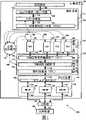
图1说明根据本发明的一个实施例的计算机网络100,其包括配置有单一逻辑NIC112的计算装置102。如图所示,计算装置102也包括(但不限于):应用程序110、操作系统111、总线驱动程序115、网络资源管理程序(NRM)113及多NIC装置114,在所述多NIC装置114上设置NIC 151、152及153。NIC 151、152及153配置为组,其共享公共IP地址并且具有单独的MAC地址。重要的是:与三个相关NIC的集合相对而言,所述组是作为单一“虚拟”1NIC表现给操作系统111及应用程序110。单一逻辑NIC 112组成此虚拟NIC。Figure 1 illustrates a
除出于简洁目的已自图1中省略的其他软件组件以外,操作系统111包括:TCP/IP堆栈121、接口对象120(展示为“App/OS套接口接口对象”)及软件接口对象123(展示为“网络堆栈接口对象(NDIS)”)。TCP/IP堆栈121经由软件接口125耦合到接口对象120并且经由软件接口126耦合到接口对象123。
单一逻辑NIC 112包括:虚拟功能驱动程序(VFD)130、功能驱动程序(FD)133、FD 134及FD 135。NRM 113包括:NRM应用程序编程接口(API)140、NRM网络功能软件141及硬件抽象层(HAL)142。NRM网络功能软件141经由软件接口148耦合到HAL 142并且经由软件接口149耦合到NRM API 140。多NIC装置114包括外部硬件接口150(展示为“至芯片内部的接口”),所述NIC 151、NIC 152及NIC 153分别经由硬件接口155、156及157耦合到所述外部硬件接口150。所述硬件接口150经由硬件/软件接口154耦合到NRM 113的HAL 142。Single logical NIC 112 includes: virtual function driver (VFD) 130, function driver (FD) 133, FD 134 and FD 135. NRM 113 includes: NRM application programming interface (API) 140, NRM
总线驱动程序115分别经由软件句柄(software handle)165、164、162、161及160耦合到NRM 113、VFD 130、FD 133、FD 134及FD 135中的每一者。如在下文中更详细描述,对于各NIC而言,软件句柄145、146及147根据具体情况而定,在针对所述NIC的功能驱动程序与NRM 113中代表所述NIC的软件对象之间建立通信信道。类似地,软件句柄143在VFD 130与NRM 113中代表NIC组的软件对象之间建立通信信道。VFD130经由软件绑定166耦合到TCP/IP堆栈121。
计算机网络100另外包括交换器104及远程机器106。交换器104经由网络接口105耦合到远程机器106并且分别经由网络接口107、108及109耦合到NIC 151、152及153。
如在此处更详细地描述,本发明为操作系统111提供单一逻辑NIC 112。此单一逻辑NIC 112与NRM 113一起独立于操作系统111实施负载平衡、故障排除及故障后恢复,其改进计算装置102的可靠性及联网处理量。单一逻辑NIC 112也支持802.1X与802.1Q网络标准,其可改进计算装置102与网络100中的其他机器之间通信的安全性。此外,计算装置102中的相关装置驱动程序及硬件组件经配置以自动产生且持续维持单一逻辑NIC 112。所得配置得以自动且持续维持以确保系统重新启动时配置稳定且可靠。As described in more detail herein, the present invention provides a single
总线架构bus architecture
通常,操作系统经由一个或一个以上直接控制其相应硬件装置的装置驱动程序与硬件装置通信。装置驱动程序也可经由一个或一个以上中间装置驱动程序与硬件装置通信以间接控制其相应硬件装置。此间接控制的一个实例为:装置驱动程序通过耦合到针对硬件总线的中间装置驱动程序来控制硬件总线上的硬件装置(例如数码相机装置驱动程序通过耦合到针对通用串行总线(USB)的装置驱动程序而控制USB上的数码相机)。USB装置驱动程序直接控制总线上的通信,并且数码相机装置驱动程序通过其与USB装置驱动程序的通信而经由总线间接控制与数码相机的通信。此种架构通常产生复杂的软件与硬件层次,其必须经适当管理以实现系统内的操作系统与硬件装置之间的理想互动。此种软件与硬件层次的技术复杂性促使开发不同软件架构以便以稳定、面向对象的方式管理软件-硬件通信。Typically, an operating system communicates with hardware devices via one or more device drivers that directly control their corresponding hardware devices. Device drivers may also communicate with hardware devices via one or more intermediate device drivers to indirectly control their respective hardware devices. An example of this indirect control is when a device driver controls a hardware device on a hardware bus by coupling to an intermediary device driver for the hardware bus (for example, a digital camera device driver couples to a device driver for the Universal Serial Bus (USB) driver to control a digital camera on USB). The USB device driver directly controls communication on the bus, and the digital camera device driver indirectly controls communication with the digital camera via the bus through its communication with the USB device driver. Such architectures typically result in complex layers of software and hardware that must be properly managed to achieve the desired interaction between the operating system and hardware devices within the system. This technological complexity at the software and hardware level has prompted the development of different software architectures to manage software-hardware communication in a stable, object-oriented manner.
一种软件架构称为“总线架构”,其提供类属软件对象以用于产生适用于间接控制硬件总线上的硬件装置的层次化装置驱动程序架构。所述总线架构通常提供用于控制硬件总线的“类属总线驱动程序”软件对象及用于间接控制硬件总线上的各装置的“类属功能驱动程序”软件对象。所述类属总线驱动程序及类属功能驱动程序通常补充有由硬件制造商提供的附加装置专用软件,其允许类属总线驱动程序或类属功能驱动程序分别与跟硬件总线或硬件总线上的装置相关联的装置专用硬件构件通信。此种补充软件创建“装置专用总线驱动程序”或“装置专用功能驱动程序”,在本文中简称为“总线驱动程序”或“功能驱动程序”。此外,总线驱动程序包括识别哪些硬件装置耦合到硬件总线、为那些硬件装置创建功能驱动程序并且将功能驱动程序经由软件接口耦合到总线驱动程序的软件。一旦经创建,那么各功能驱动程序或将其自身经由至硬件装置的软件句柄耦合到其相应硬件装置或将其自身经由至中间软件对象的软件句柄耦合到代表硬件装置的中间软件对象。功能驱动程序也将其自身经由操作系统中的软件接口对象(例如NDIS 123)提供的至操作系统的软件绑定耦合到操作系统。由于功能驱动程序或配置有其管理其相关联的硬件装置所需的专用功能性,或能够从系统内的另一实体处访问所述功能性(例如,经由至操作系统的面向网络的呼叫),功能驱动程序能够充当间接耦合操作系统及其相应硬件装置的接口对象。One type of software architecture is called a "bus architecture" that provides generic software objects for creating a hierarchical device driver architecture suitable for indirect control of hardware devices on a hardware bus. The bus architecture typically provides "generic bus driver" software objects for controlling the hardware bus and "generic function driver" software objects for indirectly controlling devices on the hardware bus. The generic bus driver and the generic function driver are usually supplemented with additional device-specific software provided by the hardware manufacturer, which allows the generic bus driver or the generic function driver to communicate with the hardware bus or the hardware bus respectively. The device-specific hardware components associated with the device communicate. Such supplemental software creates a "device-specific bus driver" or "device-specific function driver", referred to herein simply as a "bus driver" or "function driver". Additionally, the bus driver includes software that identifies which hardware devices are coupled to the hardware bus, creates function drivers for those hardware devices, and couples the function drivers to the bus driver via a software interface. Once created, each function driver either couples itself to its corresponding hardware device via a software handle to the hardware device or couples itself to an intermediate software object representing the hardware device via a software handle to the intermediate software object. A function driver also couples itself to the operating system via software bindings to the operating system provided by software interface objects in the operating system (eg, NDIS 123). Because a function driver is either configured with the dedicated functionality it needs to manage its associated hardware device, or can access said functionality from another entity within the system (e.g., via a network-oriented call to the operating system) , the function driver can serve as an interface object that indirectly couples the operating system and its corresponding hardware devices.
重要的是,操作系统对给定功能驱动程序的控制程度决定操作系统对对应于所述功能驱动程序的硬件装置的控制程度。由于总线驱动程序控制系统内不同功能驱动程序的创建且功能驱动程序创建其自身与操作系统之间的软件接口,因此总线架构可用于通过直接控制创建哪些功能驱动程序及通过间接控制所述功能驱动程序如何耦合到操作系统来控制操作系统与不同硬件装置之间的互动。此外,一旦经配置,那么总线架构通过将这一信息存储在注册表或外部数据文件中来持续维持总线驱动程序、功能驱动程序的配置及其耦合,以确保在计算装置重新启动时可靠地重新创建层次化驱动程序配置。用于将配置信息存储在注册表或存储在外部数据文件中的方法已为所属领域的技术人员所熟知。因此,总线架构提供用于创建并维持层次化、持续装置驱动程序的精密软件架构,且所述软件架构可用于控制操作系统与对应于装置驱动程序的硬件装置的互动。Importantly, the degree of control the operating system has over a given function driver determines the degree of control the operating system has over the hardware device corresponding to that function driver. Since the bus driver controls the creation of the different function drivers within the system and the function driver creates the software interface between itself and the operating system, the bus architecture can be used to directly control which function drivers are created and through indirect control of said function drivers How programs are coupled to the operating system to control the interaction between the operating system and different hardware devices. In addition, once configured, the bus architecture persists the configuration of bus drivers, function drivers, and their coupling by storing this information in the registry or external data files to ensure reliable restart when the computing device is restarted. Create a hierarchical driver configuration. Methods for storing configuration information in a registry or in external data files are well known to those skilled in the art. Thus, the bus architecture provides a sophisticated software architecture for creating and maintaining hierarchical, persistent device drivers that can be used to control the interaction of the operating system with the hardware devices corresponding to the device drivers.
本发明以新颖方式利用总线架构来将一NIC组作为单一逻辑NIC表现给操作系统。所述单一逻辑NIC包括针对所述组中的各NIC的功能驱动程序及称为虚拟功能驱动程序的附加功能驱动程序,以用于处理操作系统与NIC组之间的常规联网通信。通过将所有常规网络通信量及配置通信配置为在操作系统与虚拟功能驱动程序之间而不是在操作系统与个别功能驱动程序或NIC之间流动,操作系统被有效地防止重新配置个别NIC或NIC组并防止尝试在组内于个别NIC之间分布网络通信量。如在下文中更详细地描述,这一配置是通过由用户级程序(user-level process)选择性地去除功能驱动程序与操作系统之间的所有绑定且通过引入中间软件对象(NRM)来智能化地控制NIC的配置及通信来实现。The present invention utilizes the bus architecture in a novel way to present a group of NICs to the operating system as a single logical NIC. The single logical NIC includes a function driver for each NIC in the group and an additional function driver called a virtual function driver for handling normal networking communications between the operating system and the group of NICs. The operating system is effectively prevented from reconfiguring individual NICs or NICs by configuring all regular network traffic and configuration traffic to flow between the operating system and the virtual function driver rather than between the operating system and the individual function driver or NIC group and prevents attempts to distribute network traffic between individual NICs within the group. As described in more detail below, this configuration is achieved by selectively removing all bindings between the function driver and the operating system by a user-level process and intelligently by introducing middleware objects (NRMs). It can be realized by controlling the configuration and communication of the NIC systematically.
返回参看图1,NRM 113使NIC 151、152及153组的配置及管理以及负载平衡、故障排除和故障后恢复功能的智能供应能够改进计算装置102的联网处理量及可靠性。NRM 113将代表NIC 151、152及153组的句柄提供给虚拟功能驱动程序130,进而允许在VFD 130与NRM 113之间的常规网络通信量和配置通信。在NRM 113中,网络通信量可分布在个别NIC 151、152及153上。NRM 113也可将关于NIC 151、152及153组的状态信息(例如聚集通信处理量或聚集链接状态指示)经由VFD 130传输给操作系统111。此外,如在下文中更详细地描述,NRM 113可将句柄提供给个别NIC 151、152及153以启用需要NCI级通信的先进联网特征,例如802.1X。因此,单一逻辑NIC 112(其包括VFD 130、FD 133、FD 134及FD 135)连同NRM 113一起在操作系统111与NIC 151、152及153组之间创建一个虚拟接口,所述虚拟接口限制操作系统111与个别NIC 151、152及153之间互动的能力。举例而言,在不同NIC 151、152及153故障或返回操作的情况下,NRM 113可重新配置网络通信量以实现特定NIC的去除或添加而不会使任何用户或操作系统察觉到重新配置。此外,这一结构允许NRM 113智能化地配置NIC 151、152及153且有效地管理其各自的网络连接以根据实际情况而定来优化负载平衡、故障排除或故障后恢复功能。Referring back to FIG. 1 ,
当设立图1中所示的架构时,总线驱动程序115创建FD 133、FD 134及FD 135并且随后将其自身分别经由软件句柄162、161及160耦合到这些功能驱动程序中的每一驱动程序。最初,FD 133、FD 134及FD 135中的每一者将其自身经由NDIS 123提供的软件绑定耦合到TCP/IP堆栈121。此外,FD 133将其自身经由NRM API 140提供的句柄145耦合到NRM 113中的代表NIC 151的软件对象(未图示),进而在FD 133与NIC 151之间创建通信信道;FD 134将其自身经由NRM API 140提供的句柄146耦合到NRM 113中的代表NIC 152的软件对象(未图示),进而在FD 134与NIC 152之间创建通信信道;并且FD 135将其自身经由NRM API 140提供的句柄147耦合到NRM 113中的代表NIC153的软件对象(未图示),进而在FD 135与NIC 153之间创建通信信道。如将在下文中更详细描述,这些通信信道中的每一信道可在操作系统111与个别NIC 151、152及153而非NIC组直接通信时(例如当传达802.1X安全凭证请求时)的情况中使用。When setting up the architecture shown in FIG. 1,
此外,总线驱动程序115创建VFD 130以为单一逻辑NIC 112提供至操作系统111的接口。此外,VFD 130将其自身经由NRM API 140提供的句柄143耦合到NRM 113中的代表NIC 151、152及153组的软件对象(未图示)并且经由NDIS 123提供的绑定166耦合到TCP/IP堆栈121,进而在TCP/IP堆栈121与NIC组之间创建通信信道。这一通信信道可在操作系统111与NIC组直接通信时(例如当操作系统111中的TCP/IP堆栈121管理并处理常规TCP/IP通信时)的情况中使用。In addition,
重要的是:在总线驱动程序115创建这些功能驱动程序之后,用户级程序去除TCP/IP堆栈121与所述FD 133、FD 134及FD 135中的每一者之间的绑定。结果,如图所示,操作系统111与单一逻辑NIC 112之间的唯一绑定为绑定166。因此,绑定166为操作系统111与单一逻辑NIC 112之间的用于常规联网通信及用于配置及状态信息通信的单一软件接口。去除操作系统111与FD 133、FD 134及FD 135之间的绑定确保防止操作系统111及第三方单方面重新配置NIC 151、152及153。如前文所述,所得配置由并入总线架构软件中的下层存储机构持续存储。在重新启动时,从存储器中读取计算装置102的配置,并且重新创建总线驱动程序115、FD 130、FD 133、FD 134及FD 135以及绑定166及耦合162、161、160、143、145、146及147。Important: After the
NRM 113包含NRM网络功能软件141,其包括本地TCP/IP堆栈(未图示)且实施NIC优化功能和由NRM 113实施的所有专用联网功能。因此,可由NRM 113本地或常规地由操作系统111中的TCP/IP堆栈121管理并处理TCP/IP连接。然而,如所属领域的技术人员所认识到:将这一类型的功能性并入NRM 113中将使得NRM 113能够通过优化其配置并管理NIC 151、152及153上的网络连接来比操作系统111通过常规装置驱动程序架构更好地改进多NIC装置114的通信处理量。例如,NRM 113具有其可访问而操作系统111正常不可访问的信息,例如经由专用网络连接传输的通信量的量。这一类型的信息使得NRM 113尤其在负载平衡及故障排除方面能够作出比操作系统111更多获悉的网络管理决策。此外,NRM 113包括使多NIC装置114的硬件与NRM网络功能软件141分离的硬件抽象层142,进而使NRM网络功能软件141与随后对多NIC装置114的硬件改动无关。
如先前在本文中所述,NRM 113也经配置为将关于单一逻辑NIC 112的状态信息经由VFD 130报告给操作系统111。举例而言,单一逻辑NIC 112可将代表组内个别NIC151、152及153的聚集处理量的处理量报告给操作系统111。因此,如果NIC 151、152及153中的每一者的个别处理量均为每秒100兆位(Mbps),那么报告给操作系统111的单一逻辑NIC 112的处理量将为300 Mbps。NRM 113经配置以随着从组中添加或去除NIC而调整单一逻辑NIC 112的聚集处理量。例如,如果将第四个同样具100 Mbps处理量的NIC添加到所述组,那么报告给操作系统111的单一逻辑NIC 112的处理量将为400Mbps。同样,如果NIC 152出故障,那么单一逻辑NIC 112的处理量将为200 Mbps。此外,NRM 113可将指示是否启用NIC 151、152及153中的一个或一个以上NIC的聚集链接状态指示报告给操作系统111。例如,如果NIC 151、152及153中的一个或一个以上为活动的,那么报告给操作系统111的聚集链接状态将指示单一逻辑NIC 112为被“启用”的。然而,如果禁用了所有NIC,那么聚集链接状态报告将指示单一逻辑NIC 112为被“禁用”的。将譬如聚集处理量及聚集链接状态的状态信息提供给操作系统111,允许操作系统111将关于单一逻辑NIC 112的状态信息报告给用户或网络监控软件。As previously described herein,
总而言之,所揭示的架构具有以下超过现有技术LBFO实施的优点:第一,LBFO功能是在NRM 113处实施,其中监控NIC级操作参数,进而在实施负载平衡、故障排除及故障后恢复操作时,使软件级之间出现的通信量最小化;第二,NRM 113可以访问网络通信量信息及操作系统111不必要可访问的其他NIC级操作参数,此允许NRM 113作出更多获悉的负载平衡、故障排除及故障后恢复决策;第三,可为复杂LBFO管理及操作专门定制NRM网络功能软件141,进而相对于现有技术实施改进与LBFO相关的性能;最后,操作系统111与用户可见单一逻辑NIC 112有效地限制操作系统111或用户重新配置个别NIC 151、152及153或NIC组的能力。此外,所得配置是创建并持续维持的。In summary, the disclosed architecture has the following advantages over prior art LBFO implementations: First, LBFO functionality is implemented at the
802.1X支持802.1X support
802.1X中的NIC验证通常始于NIC向交换器请求802.1X凭证,交换器将802.1X请求转送给凭证服务器。如果802.1X请求被核准,那么凭证服务器将802.1X凭证传输给交换器,交换器将凭证转送给请求NIC。一旦NIC具有有效凭证,NIC就经验证与交换器通信,直到凭证过期或NIC与交换器之间的网络连接中断(例如,如果网络线缆断开或NIC被禁用)。NIC向802.1X兼容的交换器请求及接收凭证的联网协议已为所属领域的技术人员所熟知。NIC authentication in 802.1X typically begins with the NIC requesting an 802.1X credential from the switch, which forwards the 802.1X request to the credential server. If the 802.1X request is approved, the certificate server transmits the 802.1X certificate to the switch, which forwards the certificate to the requesting NIC. Once the NIC has valid credentials, the NIC is authenticated to communicate with the switch until the credentials expire or the network connection between the NIC and the switch is lost (eg, if the network cable is disconnected or the NIC is disabled). Networking protocols for NICs to request and receive credentials from 802.1X compliant switches are well known to those skilled in the art.
在本发明的一个实施例中,验证一特定NIC的802.1X安全凭证请求源自操作系统111中的802.1X软件且自802.1X软件经由NIC功能驱动程序传达到NRM 113,所述NRM113将凭证请求经由NIC转送到交换器104。不同于将TCP/IP通信量传输到NRM 113(通信量在此处分布于组中的不同NIC 151、152及152之间)的自TCP/IP堆栈121到VFD 130的常规TCP/IP通信,凭证请求经由验证的实际NIC传输。举例而言,如果NIC 151经验证,那么802.1X软件将802.1X安全凭证请求传输到FD 133,其随后将凭证请求经由句柄145传输到NIC 151。一旦由NIC接收到,凭证请求就自NIC转送到交换器104。In one embodiment of the invention, the 802.1X security credential request to authenticate a particular NIC originates from the 802.1X software in the
图2说明图1的计算装置102,其配置有单一逻辑NIC 112以使用802.1X验证个别NIC 151、152及153。操作系统111包括802.1X软件程序222,其经由软件接口227耦合到NDIS 123。802.1X软件程序222也分别经一系列软件绑定268、269及270耦合到FD 133、FD 134及FD 135,所述软件绑定在功能驱动程序创建时由功能驱动程序自动向NDIS 123请求。不同于由总线驱动程序115最初请求且由NDIS 123为每一个别功能驱动程序提供且随后由用户级程序去除的TCP/IP绑定,802.1X绑定268、269及270为持续的,意思是其为整体系统架构的永久部分,且随计算装置102的重新启动而重新创建。然而,重要的是,对操作系统111的802.1X绑定也由总线驱动程序115请求且由NDIS 123为VFD 130提供,但此绑定由用户级程序去除,因为作为单一逻辑NIC 112表现给操作系统111的NIC组不尝试组级802.1X验证。事实上,在构成NIC 151、152及153级处实施802.1X验证。以此方式,图1的总线驱动程序架构可经调整而管理802.1X协议的特别绑定需要,进而使计算装置102能够支持组中每一NIC 151、152及153的此重要安全协议。FIG. 2 illustrates the
802.1Q支持802.1Q support
在本发明的一个实施例中,计算装置102可具有一个或一个以上VLAN分配,其对组中NIC 151、152及153中的每一者是公共的。每一所述VLAN分配代表为所述VLAN定义的IP地址范围内的计算装置102的一IP地址。此外,对于每一VLAN,存在单一逻辑NIC 112与TCP/IP堆栈121之间的用于交换与VLAN相关联的TCP/IP通信的独立绑定。用于配置一系列的IP地址作为VLAN且分配机器给VLAN的程序已为所属领域的技术人员所熟知。重新配置计算装置102以支持第一VLAN分配需要总线驱动程序115添加VLAN属性331到现有VFD 130且调节VFD 130与TCP/IP堆栈121之间的绑定166以耦合VLAN属性331与TCP/IP堆栈121。每一附加VLAN分配需要总线驱动程序115添加另一虚拟功能驱动程序到单一逻辑NIC 112且向NDIS 123请求软件绑定,以将附加虚拟功能驱动程序耦合到TCP/IP堆栈121以用于交换与附加VLAN相关联的TCP/IP通信。附加虚拟功能驱动程序也以与VFD 130耦合到NRM 113类似的方式耦合到NRM113,以启用TCP/IP堆栈121与NIC 151、152及153组之间的通信。此外,操作系统111中的802.1X软件程序222与最初在总线驱动程序115创建附加虚拟功能驱动程序时创建的附加虚拟功能驱动程序之间的绑定如同对于VFD 130去除802.1X绑定而由用户级程序去除。在此配置中,计算装置102可与分配给跟包括于单一逻辑NIC 112中的任何虚拟功能驱动程序相关联的任何VLAN的计算装置通信,且计算装置102被防止与未分配给所述VLAN的计算装置通信,因而支持802.1Q网络标准。In one embodiment of the invention,
图3说明包括单一逻辑NIC 112的计算装置102,其中NIC 151、152及153被分配给两个不同的VLAN。如图所示,单一逻辑NIC 112包括VFD 130、VFD 332、FD 133、FD 134及FD 135。VFD 130包括一经由软件绑定166耦合到TCP/IP堆栈121的VLAN属性331。VFD 130分别经一对软件句柄164及143耦合到总线驱动程序115及NRM API140。VFD 332经由软件绑定367耦合到TCP/IP堆栈121且另外分别经由软件句柄363及344耦合到总线驱动程序115及NRM API 140。如图3说明,通过添加VLAN属性331到VFD 130且通过调节绑定166以耦合VLAN属性331与TCP/IP堆栈121,提供对于计算装置102的第一VLAN分配。通过创建VFD 332且经由如上文所述的软件句柄及绑定而将其耦合到TCP/IP堆栈121、NRM API 140及总线驱动程序115,提供对于计算装置102的第二VLAN分配。重要的是,VLAN属性331及VFD 332被耦合到TCP/IP堆栈121,而FD133、FD134及FD135被耦合到802.1X软件程序222。此配置限制与单一逻辑NIC 112内的传达VLAN通信量的组件的TCP/IP通信,且限制经由个别NIC 151、152及153与单一逻辑NIC 112内的传达802.1X凭证请求的组件的802.1X通信。FIG. 3 illustrates
尽管上述内容针对本发明的实施例,但可在不偏离本发明的基本范围的情况下设计本发明的其他和另外的实施例。举例而言,在各种实施例中,NIC组可包括任意数目的NIC。在计算装置102包括一个NIC的实施例中,对所述NIC存在一个功能驱动程序,且软件绑定将功能驱动程序耦合到TCP/IP堆栈212以处理NIC与操作系统111之间的常规网络通信。此外,如果适用,那么另一软件绑定将功能驱动程序耦合到802.1X软件程序222以用于使用802.1X验证NIC。为支持第一VLAN分配,将创建第一虚拟功能驱动程序,且将传送TCP/IP堆栈121与功能驱动程序之间的软件绑定,从而耦合第一虚拟功能驱动程序与TCP/IP堆栈121以使VLAN通信量能在NIC与TCP/IP堆栈121之间传达。对于每一附加VLAN分配,将连同一软件绑定创建另一虚拟功能驱动程序,所述软件绑定将附加虚拟功能驱动程序耦合到TCP/IP堆栈121以使与附加VLAN相关联的网络通信量在NIC与TCP/IP堆栈121之间传达。除以上所述之外,图1到图3中所示的软件组件及层次为例示性的且可不偏离本发明的范围而实施其他功能上等效的软件组件或其他层次。此外,计算装置102可为桌上型电脑、服务器、膝上型电脑、掌上电脑、个人数字助理、书写板电脑、游戏机、移动电话或任何其他类型的处理信息的类似装置。While the foregoing is directed to embodiments of the invention, other and further embodiments of the invention may be devised without departing from the basic scope of the invention. For example, in various embodiments, a NIC group may include any number of NICs. In embodiments where
因而,本发明的范围由上述权利要求书确定。Accordingly, the scope of the invention is to be determined by the following claims.
Claims (10)
Applications Claiming Priority (2)
| Application Number | Priority Date | Filing Date | Title |
|---|---|---|---|
| US11/303,779 | 2005-12-15 | ||
| US11/303,779US8572288B2 (en) | 2005-12-15 | 2005-12-15 | Single logical network interface for advanced load balancing and fail-over functionality |
Related Child Applications (1)
| Application Number | Title | Priority Date | Filing Date |
|---|---|---|---|
| CN2013100713659ADivisionCN103152282A (en) | 2005-12-15 | 2006-12-15 | Single logical network interface for advanced load balancing and fail-over functionality |
Publications (1)
| Publication Number | Publication Date |
|---|---|
| CN101001177Atrue CN101001177A (en) | 2007-07-18 |
Family
ID=38264574
Family Applications (2)
| Application Number | Title | Priority Date | Filing Date |
|---|---|---|---|
| CNA2006101681782APendingCN101001177A (en) | 2005-12-15 | 2006-12-15 | Single logical network interface for advanced load balancing and troubleshooting functionality |
| CN2013100713659APendingCN103152282A (en) | 2005-12-15 | 2006-12-15 | Single logical network interface for advanced load balancing and fail-over functionality |
Family Applications After (1)
| Application Number | Title | Priority Date | Filing Date |
|---|---|---|---|
| CN2013100713659APendingCN103152282A (en) | 2005-12-15 | 2006-12-15 | Single logical network interface for advanced load balancing and fail-over functionality |
Country Status (4)
| Country | Link |
|---|---|
| US (1) | US8572288B2 (en) |
| JP (1) | JP4515441B2 (en) |
| CN (2) | CN101001177A (en) |
| TW (1) | TWI360781B (en) |
Cited By (1)
| Publication number | Priority date | Publication date | Assignee | Title |
|---|---|---|---|---|
| CN101909054A (en)* | 2010-07-15 | 2010-12-08 | 华中科技大学 | A Method for Aggregating Multiple Network Interface Cards in a Virtualization Environment |
Families Citing this family (19)
| Publication number | Priority date | Publication date | Assignee | Title |
|---|---|---|---|---|
| TWI288352B (en)* | 2005-11-17 | 2007-10-11 | Benq Corp | Processing methods and systems for drivers |
| US7693044B2 (en)* | 2005-12-15 | 2010-04-06 | Nvidia Corporation | Single logical network interface for advanced load balancing and fail-over functionality |
| US8572288B2 (en) | 2005-12-15 | 2013-10-29 | Nvidia Corporation | Single logical network interface for advanced load balancing and fail-over functionality |
| DE102005061662A1 (en)* | 2005-12-22 | 2007-06-28 | Giesecke & Devrient Gmbh | Auxiliary unit installing method for host-computer, involves installing setting process on computer to detect whether operation routine is transmitted, where process verifies whether information transmitted by unit is stored in computer |
| JP4965144B2 (en)* | 2006-03-20 | 2012-07-04 | 株式会社リコー | Communication device |
| JP4802159B2 (en)* | 2007-08-23 | 2011-10-26 | 株式会社エヌ・ティ・ティ・ドコモ | Network equipment |
| US8223649B2 (en)* | 2008-03-25 | 2012-07-17 | Intel Corporation | Method and apparatus for sending a packet from a source node to a destination node in the same broadcast domain |
| US7921327B2 (en)* | 2008-06-18 | 2011-04-05 | Dell Products L.P. | System and method for recovery from uncorrectable bus errors in a teamed NIC configuration |
| US9191281B2 (en)* | 2008-11-05 | 2015-11-17 | Telefonaktiebolaget L M Ericsson (Publ) | Systems and methods for configuring a demarcation device |
| JP5272709B2 (en)* | 2008-12-19 | 2013-08-28 | 富士通株式会社 | Address assignment method, computer, physical machine, program, and system |
| US8265973B2 (en) | 2010-03-11 | 2012-09-11 | International Business Machines Corporation | Analytic-based scaling of information technology resources |
| US9838342B2 (en)* | 2013-05-15 | 2017-12-05 | Dell Products L.P. | Network interface connection teaming system |
| US10511608B2 (en)* | 2014-10-30 | 2019-12-17 | Lenovo (Singapore) Pte. Ltd. | Aggregate service with file sharing |
| CN105302611B (en)* | 2015-11-13 | 2019-10-25 | 中标软件有限公司 | A kind of method and system of starting computer system under Linux |
| US9921991B2 (en) | 2015-11-24 | 2018-03-20 | Nicira, Inc. | Systems and methods for flipping NIC teaming configuration without interfering live traffic |
| JP2019009638A (en)* | 2017-06-26 | 2019-01-17 | ルネサスエレクトロニクス株式会社 | Radio communication device, system, and method |
| CN113157447B (en)* | 2021-04-13 | 2023-08-29 | 中南大学 | RPC load balancing method based on intelligent network card |
| US12124342B2 (en)* | 2022-04-29 | 2024-10-22 | Dell Products L.P. | Recovery of smart network interface controller operating system |
| CN116233075A (en)* | 2023-02-10 | 2023-06-06 | 济南浪潮数据技术有限公司 | Method, device and equipment for IP address allocation management under cloud platform |
Family Cites Families (25)
| Publication number | Priority date | Publication date | Assignee | Title |
|---|---|---|---|---|
| US6253334B1 (en)* | 1997-05-13 | 2001-06-26 | Micron Electronics, Inc. | Three bus server architecture with a legacy PCI bus and mirrored I/O PCI buses |
| US6105151A (en)* | 1997-05-13 | 2000-08-15 | 3Com Corporation | System for detecting network errors |
| US6687758B2 (en)* | 2001-03-07 | 2004-02-03 | Alacritech, Inc. | Port aggregation for network connections that are offloaded to network interface devices |
| US6229538B1 (en)* | 1998-09-11 | 2001-05-08 | Compaq Computer Corporation | Port-centric graphic representations of network controllers |
| US20010052084A1 (en)* | 1998-11-10 | 2001-12-13 | Jiandoug Huang | Apparatus and methods for providing fault tolerance of networks and network interface cards |
| JP2000244526A (en)* | 1999-02-23 | 2000-09-08 | Hitachi Ltd | Multiplexed network connection device system |
| JP2000244527A (en) | 1999-02-23 | 2000-09-08 | Adtec:Kk | Transmission method, transmitter and lan system |
| US6512774B1 (en)* | 1999-03-18 | 2003-01-28 | 3Com Corporation | Fail over with multiple network interface cards |
| US6567377B1 (en)* | 1999-03-18 | 2003-05-20 | 3Com Corporation | High performance load balancing of outbound internet protocol traffic over multiple network interface cards |
| US6560630B1 (en)* | 1999-03-18 | 2003-05-06 | 3Com Corporation | Receive load balancing and fail over with multiple network interface cards |
| US6590861B1 (en)* | 1999-03-18 | 2003-07-08 | 3Com Corporation | Combining virtual local area networks and load balancing with fault tolerance in a high performance protocol |
| US6683882B1 (en)* | 1999-11-09 | 2004-01-27 | 3Com Corporation | Method and system for directing transmission of IPX control packets to influence reception of IPX data packets |
| US6941377B1 (en)* | 1999-12-31 | 2005-09-06 | Intel Corporation | Method and apparatus for secondary use of devices with encryption |
| US7082530B1 (en)* | 1999-12-31 | 2006-07-25 | Intel Corporation | Method and apparatus for accelerating hardware encryption with multiple networking interfaces |
| US7089335B2 (en)* | 2000-10-30 | 2006-08-08 | Microsoft Corporation | Bridging multiple network segments and exposing the multiple network segments as a single network to a higher level networking software on a bridging computing device |
| US6941405B2 (en)* | 2001-08-21 | 2005-09-06 | 02Micro International Limited | System and method capable of offloading converter/controller-specific tasks to a system microprocessor |
| US7463585B2 (en)* | 2002-05-16 | 2008-12-09 | Broadcom Corporation | System, method, and apparatus for load-balancing to a plurality of ports |
| US7111303B2 (en)* | 2002-07-16 | 2006-09-19 | International Business Machines Corporation | Virtual machine operating system LAN |
| ATE528897T1 (en) | 2003-09-10 | 2011-10-15 | Microsoft Corp | MULTIPLE OFFLOADING OF NETWORK STATUS OBJECTS WITH FAILOVER EVENT SUPPORT |
| US7752635B2 (en)* | 2003-12-18 | 2010-07-06 | Intel Corporation | System and method for configuring a virtual network interface card |
| US7580415B2 (en)* | 2005-04-27 | 2009-08-25 | Hewlett-Packard Development Company, L.P. | Aggregation of hybrid network resources operable to support both offloaded and non-offloaded connections |
| US7872965B2 (en)* | 2005-08-01 | 2011-01-18 | Hewlett-Packard Development Company, L.P. | Network resource teaming providing resource redundancy and transmit/receive load-balancing through a plurality of redundant port trunks |
| US7646708B2 (en)* | 2005-08-01 | 2010-01-12 | Hewlett-Packard Development Company, L.P. | Network resource teaming combining receive load-balancing with redundant network connections |
| US20070110244A1 (en)* | 2005-11-16 | 2007-05-17 | Kapil Sood | Method, apparatus and system for enabling a secure wireless platform |
| US8572288B2 (en) | 2005-12-15 | 2013-10-29 | Nvidia Corporation | Single logical network interface for advanced load balancing and fail-over functionality |
- 2005
- 2005-12-15USUS11/303,779patent/US8572288B2/enactiveActive
- 2006
- 2006-12-15JPJP2006338932Apatent/JP4515441B2/ennot_activeExpired - Fee Related
- 2006-12-15CNCNA2006101681782Apatent/CN101001177A/enactivePending
- 2006-12-15TWTW095147167Apatent/TWI360781B/ennot_activeIP Right Cessation
- 2006-12-15CNCN2013100713659Apatent/CN103152282A/enactivePending
Cited By (2)
| Publication number | Priority date | Publication date | Assignee | Title |
|---|---|---|---|---|
| CN101909054A (en)* | 2010-07-15 | 2010-12-08 | 华中科技大学 | A Method for Aggregating Multiple Network Interface Cards in a Virtualization Environment |
| CN101909054B (en)* | 2010-07-15 | 2012-12-19 | 华中科技大学 | Method for aggregating multiple network interface cards in virtualized environment |
Also Published As
| Publication number | Publication date |
|---|---|
| JP2007193779A (en) | 2007-08-02 |
| TW200745954A (en) | 2007-12-16 |
| JP4515441B2 (en) | 2010-07-28 |
| US20070168563A1 (en) | 2007-07-19 |
| TWI360781B (en) | 2012-03-21 |
| US8572288B2 (en) | 2013-10-29 |
| CN103152282A (en) | 2013-06-12 |
Similar Documents
| Publication | Publication Date | Title |
|---|---|---|
| JP4515441B2 (en) | Single logical network interface for improved load balancing and failover capabilities | |
| US7783788B1 (en) | Virtual input/output server | |
| US7693044B2 (en) | Single logical network interface for advanced load balancing and fail-over functionality | |
| US8886783B2 (en) | System and method for providing secure subnet management agent (SMA) based fencing in an infiniband (IB) network | |
| US20200145297A1 (en) | Dynamic reservation protocol for 5G network slicing | |
| US9262155B2 (en) | System and method for supporting in-band/side-band firmware upgrade of input/output (I/O) devices in a middleware machine environment | |
| US9219683B2 (en) | Unified infrastructure over ethernet | |
| US20100169467A1 (en) | Method and apparatus for determining a network topology during network provisioning | |
| US8713649B2 (en) | System and method for providing restrictions on the location of peer subnet manager (SM) instances in an infiniband (IB) network | |
| CN104919762B (en) | Control method, control device and processor in software-defined networking | |
| EP3982600B1 (en) | Method and apparatus for configuring a quality of service policy for a service | |
| EP3896927A1 (en) | Packet transmission method, apparatus, and system | |
| CN105704042A (en) | Message processing method, BNG and BNG cluster system | |
| CN108183849A (en) | Device management method, equipment and system based on L2TP | |
| CN101459530A (en) | Method, system and equipment for wireless network management and maintenance | |
| WO2023035777A1 (en) | Network configuration method, proxy component, controller, electronic device and storage medium | |
| CN1985492B (en) | Method and system for supporting iSCSI read operation and iSCSI chimney | |
| CN109039680B (en) | A method, system and BNG for switching main broadband network gateway BNG and standby BNG | |
| Cisco | Cisco IOS Bridging and IBM Networking Configuration Guide Release 12.1 | |
| Cisco | Bridging and IBM Networking Configuration Guide Cisco IOS Release 11.3 | |
| CN102780600B (en) | Communication system |
Legal Events
| Date | Code | Title | Description |
|---|---|---|---|
| C06 | Publication | ||
| PB01 | Publication | ||
| C10 | Entry into substantive examination | ||
| SE01 | Entry into force of request for substantive examination | ||
| C12 | Rejection of a patent application after its publication | ||
| RJ01 | Rejection of invention patent application after publication | Application publication date:20070718 |