CN1008990B - The adapter that the highway trailer train is used - Google Patents
The adapter that the highway trailer train is usedInfo
- Publication number
- CN1008990B CN1008990BCN87106981ACN87106981ACN1008990BCN 1008990 BCN1008990 BCN 1008990BCN 87106981 ACN87106981 ACN 87106981ACN 87106981 ACN87106981 ACN 87106981ACN 1008990 BCN1008990 BCN 1008990B
- Authority
- CN
- China
- Prior art keywords
- trailer
- adapter
- bogie
- road
- described adapter
- Prior art date
- Legal status (The legal status is an assumption and is not a legal conclusion. Google has not performed a legal analysis and makes no representation as to the accuracy of the status listed.)
- Expired
Links
Images


Classifications
- B—PERFORMING OPERATIONS; TRANSPORTING
- B61—RAILWAYS
- B61F—RAIL VEHICLE SUSPENSIONS, e.g. UNDERFRAMES, BOGIES OR ARRANGEMENTS OF WHEEL AXLES; RAIL VEHICLES FOR USE ON TRACKS OF DIFFERENT WIDTH; PREVENTING DERAILING OF RAIL VEHICLES; WHEEL GUARDS, OBSTRUCTION REMOVERS OR THE LIKE FOR RAIL VEHICLES
- B61F3/00—Types of bogies
- B61F3/12—Types of bogies specially modified for carrying adjacent vehicle bodies of articulated trains
- B61F3/125—Types of bogies specially modified for carrying adjacent vehicle bodies of articulated trains with more than one axle or wheel set
- B—PERFORMING OPERATIONS; TRANSPORTING
- B60—VEHICLES IN GENERAL
- B60F—VEHICLES FOR USE BOTH ON RAIL AND ON ROAD; AMPHIBIOUS OR LIKE VEHICLES; CONVERTIBLE VEHICLES
- B60F1/00—Vehicles for use both on rail and on road; Conversions therefor
- B60F1/04—Vehicles for use both on rail and on road; Conversions therefor with rail and road wheels on different axles
- B60F1/046—Semi-trailer or trailer type vehicles without own propelling units
- B—PERFORMING OPERATIONS; TRANSPORTING
- B61—RAILWAYS
- B61D—BODY DETAILS OR KINDS OF RAILWAY VEHICLES
- B61D3/00—Wagons or vans
- B61D3/10—Articulated vehicles
- B61D3/12—Articulated vehicles comprising running gear interconnected by loads
- B—PERFORMING OPERATIONS; TRANSPORTING
- B61—RAILWAYS
- B61D—BODY DETAILS OR KINDS OF RAILWAY VEHICLES
- B61D3/00—Wagons or vans
- B61D3/16—Wagons or vans adapted for carrying special loads
- B61D3/18—Wagons or vans adapted for carrying special loads for vehicles
- B61D3/182—Wagons or vans adapted for carrying special loads for vehicles specially adapted for heavy vehicles, e.g. public work vehicles, trucks, trailers
- B61D3/184—Wagons or vans adapted for carrying special loads for vehicles specially adapted for heavy vehicles, e.g. public work vehicles, trucks, trailers the heavy vehicles being of the trailer or semi-trailer type
- B—PERFORMING OPERATIONS; TRANSPORTING
- B62—LAND VEHICLES FOR TRAVELLING OTHERWISE THAN ON RAILS
- B62D—MOTOR VEHICLES; TRAILERS
- B62D53/00—Tractor-trailer combinations; Road trains
- B62D53/04—Tractor-trailer combinations; Road trains comprising a vehicle carrying an essential part of the other vehicle's load by having supporting means for the front or rear part of the other vehicle
- B62D53/06—Semi-trailers
- Y—GENERAL TAGGING OF NEW TECHNOLOGICAL DEVELOPMENTS; GENERAL TAGGING OF CROSS-SECTIONAL TECHNOLOGIES SPANNING OVER SEVERAL SECTIONS OF THE IPC; TECHNICAL SUBJECTS COVERED BY FORMER USPC CROSS-REFERENCE ART COLLECTIONS [XRACs] AND DIGESTS
- Y02—TECHNOLOGIES OR APPLICATIONS FOR MITIGATION OR ADAPTATION AGAINST CLIMATE CHANGE
- Y02T—CLIMATE CHANGE MITIGATION TECHNOLOGIES RELATED TO TRANSPORTATION
- Y02T30/00—Transportation of goods or passengers via railways, e.g. energy recovery or reducing air resistance
Landscapes
- Engineering & Computer Science (AREA)
- Mechanical Engineering (AREA)
- Transportation (AREA)
- Chemical & Material Sciences (AREA)
- Combustion & Propulsion (AREA)
- Vehicle Body Suspensions (AREA)
- Train Traffic Observation, Control, And Security (AREA)
- Vehicle Cleaning, Maintenance, Repair, Refitting, And Outriggers (AREA)
- Electric Propulsion And Braking For Vehicles (AREA)
- Tires In General (AREA)
Abstract
Translated fromChineseDescription
Translated fromChinese本发明涉及由公路挂车连接成的铁路列车,更确切地说,本发明涉及将铁路转向架与每辆挂车的端部可卸式接合的一种独特的接合器。Field of the Invention This invention relates to railroad trains joined by road trailers and, more particularly, to a unique adapter for removably engaging a railroad truck to the end of each trailer.
在美国和许多其它国家,大量的货物都是在高速公路上用挂车,或更确切地说是用半挂车运输的。因为可极其灵活地选择装卸货物的起止点,所以用公路挂车短途送货效率很高。但是在主要城镇和制造中心之间的长途运输,上述的灵活性发挥不出优势,而只会带来能源、人力和设备的较高消耗。为克服这些缺点,铁路运输已有了平车运输的方法,即将挂车放在铁路平车上运输。这种运输速度快,成本较低,节省燃料,对挂车没有磨损,并且在货运起止地之间无需卸下挂车中的货物。但是,铁路部门已经认识到,如果能取消平车,列车只是以挂车首尾相接组成,铁轨就可以承受轻得多的运输重量。取消承载挂车的平车可以降低燃料消耗,减少货运起止点的停留时间和费用,也可以减少投资,同时,还可以减少对铁轨的磨损和路基的修缮。In the United States and many other countries, a great deal of freight is transported on the highways on trailers, or rather semi-trailers. Because the starting and ending points of loading and unloading can be selected extremely flexibly, short-distance deliveries with road trailers are very efficient. However, in the long-distance transportation between major towns and manufacturing centers, the above-mentioned flexibility has no advantage, but only brings higher consumption of energy, manpower and equipment. For overcoming these shortcomings, railway transportation has had the method of flat car transportation, is about to trailer is placed on the railway flat car transportation. This type of transportation is fast, low cost, fuel efficient, does not wear on the trailer, and does not need to unload the trailer between the origin and destination of the freight. However, the railway department has realized that if the flat car can be eliminated, and the train is only composed of trailers connected end to end, the rails can bear a much lighter transport weight. Cancellation of the flat car carrying the trailer can reduce fuel consumption, reduce the stop time and cost of the starting and ending points of freight, and can also reduce investment. At the same time, it can also reduce the wear and tear on the rails and the repair of the roadbed.
有人曾指出一种制造由公路挂车组成的列车的方案,每节挂车的尾部支承在四轮双轴式转向架上。所有挂车都朝同一方向,每节挂车前部与转向架与其前面相邻的挂车相连接。用一接合器使每辆转向架与其支承的挂车可卸式接合。在美国2,963,986号专利中 公开过这种列车的实施例。但人们认为该专利中提出的接合器在结构上是不能接受的,因而,急需改进接合器。Someone once pointed out a kind of scheme of making the train that is made up of road trailer, and the afterbody of every joint trailer is supported on the four-wheel biaxle bogie. All trailers face the same direction, and the front of each trailer is connected to the bogie and the adjacent trailer in front of it. Each bogie is releasably engaged with the trailer it supports by an adapter. In U.S. Patent No. 2,963,986 Embodiments of such trains are disclosed. However, the adapter proposed in this patent is considered to be structurally unacceptable and, therefore, an improved adapter is urgently needed.
向铁路货场运送满载或空载的挂车,货场的轨道上备有一组待编组的转向架,以便组成公路挂车列车。挂车的尾部放在转向架上方,用气垫抬起挂车上的公路用轮,然后放下挂车,以便使挂车上的装置与转向架上的装置相接合,实现可卸式连接。然后,另一节挂车的前端与转向架或另一挂车的尾端相连接。这样,一节挂车的尾端和另一节挂车的前端就都支承在一辆转向架上。照此,多节挂车可连接成一任意预想长度的列车。Delivery of fully loaded or empty trailers to the railway freight yard, where a set of bogies to be marshaled is prepared on the track of the freight yard to form a road trailer train. The tail of the trailer is placed above the bogie, and the road wheels on the trailer are lifted with an air cushion, and then the trailer is lowered so that the devices on the trailer engage with the devices on the bogie to achieve a detachable connection. Then, the front end of another trailer is connected to the bogie or the rear end of another trailer. In this way, the rear end of one trailer and the front end of the other trailer are supported on a bogie. In this way, multiple trailers can be connected to form a train of any desired length.
用上述方法组成的公路挂车列车,其特点与一般货运列车不同。例如,货运货列的车厢,无论是运煤车、厢车、平车、敞蓬车、油槽车,或是其它种类的车厢都比公路挂车重。另外,通常车厢的每端由一个转向架支承,转向架大都是四轮双轴式的,不过偶或也有采用双轮单轴式的。而且,已制造了多节铰接的车厢,毗邻车厢的端部共用并装在一个公用的转向架上。The road trailer train formed by the above method has different characteristics from general freight trains. For example, the carriages of freight trains, whether they are coal cars, box cars, flat cars, cabriolets, tank cars, or other types of cars, are heavier than road trailers. In addition, each end of the car is usually supported by a bogie, and the bogies are mostly four-wheel and double-axle, but occasionally two-wheel and single-axle are used. Also, multiple articulated cars have been manufactured, the ends of adjacent cars being shared and mounted on a common bogie.
由于结构不同,一系列车厢组成的列车与公路挂车列车,在动力等方面根本不同,对一种适用的,不一定对另一种也适用。因此,在设计用于列车的挂车时,必须考虑到要增加挂车的强度,使它们能够承受铁路运行中的摇动力和扭曲力,以及列车的纵向牵引力。尽管挂车的强度增加了,实际上它们的强度仍然不如一般的货车厢,因此,悬挂系统必须改进,以确保挂车的结构足以抵抗疲劳断裂。Due to the different structures, a train composed of a series of carriages is fundamentally different from a road trailer train in terms of power, and what is applicable to one may not necessarily be applicable to the other. Therefore, when designing trailers for trains, consideration must be given to increasing the strength of the trailers so that they can withstand the shaking and twisting forces during railway operation, as well as the longitudinal traction of the train. Despite the increased strength of trailers, they are actually still not as strong as a typical truck bed, so the suspension system must be improved to ensure that the trailer structure is sufficiently resistant to fatigue fracture.
由于挂车加在轨道上的负荷比广泛应用的一般车厢轻,因此,可以选择较便宜的转向架用于公路挂车列车。但是,人们发现,这种转向架组成的列车,远不及预想的效果,特别是当列车行进速度超过每 小时45英里时,原因是由于转向架的摇摆引起的过度的横向不稳定,转向架的摇摆使标准铁路货车厢转向架的轮轴总成沿铁轨呈正弦形运动。这样就需要公路挂车列车高速行驶时,由转向架摇摆引起的横向不稳定性较低。Since the load of the trailer on the track is lighter than that of the widely used general carriage, a cheaper bogie can be selected for the road trailer train. However, people have found that the train composed of such bogies is far from the expected effect, especially when the train travels faster than every At 45 mph, the cause was excessive lateral instability due to bogie sway that caused the axle assembly of a standard railroad freight car bogie to move sinusoidally along the rails. This requires low lateral instability caused by bogie sway when road trailer trains are traveling at high speeds.
本发明的目的在于提供一种结构新颖,能够提高公路挂车列车运行性能的公路挂车列车用的新型接合器。The object of the present invention is to provide a novel adapter for road trailer trains which has a novel structure and can improve the running performance of road trailer trains.
使用本发明接合器的公路挂车列车包括:一系列首尾相接的公路挂车,每节公路挂车在其后端附近安装有公路用轮,被支承在轨道上方;可有选择地把各节挂车的公路用轮抬高至非工作位置,以便在铁轨上行驶,或降低公路用轮,与公路接触,以便在公路上行驶的装置;接合在轨道上的转向架,转向架可卸式地支承每节挂车的尾部;与挂车尾端固定连接的第一联接装置;与转向架尾端固定连接的第二联接装置;使第一联接装置与第二联接装置快速连接和脱开的装置,把一挂车的尾端挂接在相邻挂车的前端以便形成由若干这样挂接在一起并由转向架支承的公路挂车列车的挂接装置;以及在列车中支承挂车的四轮双轴摆动式转向架,它们可以控制转向架支承的挂车的横向摆动以及转向架的摇摆。The road trailer train using the adapter of the present invention includes: a series of road trailers connected end to end, each road trailer is equipped with road wheels near its rear end, and is supported above the track; device for raising road wheels to a non-operating position for traveling on rails or for lowering road wheels into contact with the road for traveling on the road; engaging bogies on the rails, the bogies detachably supporting each The tail of the trailer; the first coupling device fixedly connected to the rear end of the trailer; the second coupling device fixedly connected to the tail end of the bogie; the device for quickly connecting and disconnecting the first coupling device and the second coupling device. The rear end of a trailer is articulated on the front end of an adjacent trailer to form a hitch for a road trailer train consisting of several such articulated together and supported by a bogie; , they control the lateral oscillation of the trailer supported by the bogie as well as the sway of the bogie.
当第一联接装置与第二联接装置连接在一起时,第二联接装置与转向架能绕一垂直轴相对转动。这种转动最好应该是挂车相对于转向架能够绕一垂直轴的唯一转动。When the first coupling device and the second coupling device are connected together, the second coupling device and the bogie can relatively rotate around a vertical axis. Preferably, this rotation should be the only rotation about a vertical axis that the trailer is capable of relative to the bogie.
挂接装置可以包括一种可使相连的挂车前端和尾端绕一水平轴相对地转动的装置。The hitch may include a means for relative rotation of the front and rear ends of the attached trailer about a horizontal axis.
转向架具有一个承梁,该承梁具有一个载荷止推轴承;第二联接装置可安装在该止推轴承上,一个销子装置使第二联接装置与承梁接 合,以便能使第二联接装置与承梁之间可围绕销子装置相对转动。理想的是,在挂车与支承挂车的转向架之间的相对转动都是绕着该销子装置进行的。The bogie has a bolster with a load thrust bearing; a second linkage is mountable on the thrust bearing and a pin arrangement engages the second linkage with the bolster. combined so as to enable relative rotation around the pin device between the second coupling device and the bolster. Ideally, relative rotation between the trailer and the bogie supporting the trailer is about the pin arrangement.
美国第3,670,660号专利公开了一种四轮双轴可摆动式转向架,本说明书把该专利作为参考文献引用。这样的转向架允许接合器侧架的有限摆动,接合器装在侧架的轴箱切口内。每个侧架和一簧板之间的摇座使侧架可以如摆一样向转向架横向做一致的摆动。由于侧架的一个拉紧件与摇座的接触,侧架摆动的停止,先于装在承梁的簧板之间的横向止动器的接合。这样,便可得到承梁相对于侧架的加大横向摆动。这一横向摆动加之负载弹簧横向偏转,可改善转向架高速行驶的性能,并将其摇摆减为最小。虽然,这种转向架已用于常规铁路车厢,但尚未应用到公路挂车列车上,因为也成本高,也由于与常规列车车厢相比,动力学方面的要求有所不同,因此,人们并未设想把其用于公路挂车列车以提高运行性能。U.S. No. 3,670, No. 660 patent discloses a kind of four-wheel biaxial swingable bogie, and this specification is cited as reference. Such bogies allow limited swinging of the sideframes of the adapters, which are housed in the axle box cutouts of the sideframes. The rocker seat between each side frame and a spring plate enables the side frames to swing in a consistent lateral direction to the bogie like a pendulum. As a result of the contact of a tension member of the sideframe with the rocker, the oscillation of the sideframe is stopped prior to the engagement of the lateral stops mounted between the spring plates of the bolster. In this way, increased lateral oscillation of the bolster relative to the sideframes is obtained. This lateral oscillation, combined with the lateral deflection of the load spring, improves the performance of the bogie at high speeds and minimizes its sway. Although this type of bogie has been used on conventional railway cars, it has not been applied to road trailer trains because of the high cost and the different dynamic requirements compared to conventional train cars, so it has not been used. It is envisioned to be used in road trailer trains to improve performance.
使用本发明接合器的公路挂车列车,其第二联接装置构成一个特殊结构的接合器,它可以有益地,极好地适用于任何四轮双轴式的有承梁的转向架,包括上述的摆动式转向架,接合器纵向安装在转向架的横向承梁上。Using the road trailer train of the adapter of the present invention, its second coupling device constitutes an adapter of a special structure, which can be beneficially and excellently adapted to any four-wheel double-axle bogie with a bolster, including the above-mentioned Swing type bogie, the adapter is installed longitudinally on the transverse bolster of the bogie.
按照本发明的接合器,将第一公路挂车的一端支承于铁路转向架中心盘槽的另一端以形成一纵向的至少二公路挂车组成的列车,所述接合器包括至少一个能与所述第一公路挂车的至少一配合表面形成支承接触的上表面以及一个可以在所述中心盘槽中转动的轴承凸台,所述接合器的特征在于:形状互补的上、下两部分相互连接而又可相互垂直移动一个预定的距离;有弹性的可压缩装置位于接合器上、下两 部分的横向相隔开的端部之间,挂车的摇动使其上负荷增加时,所述有弹性的可压缩装置可被垂直地压缩。所述的至少一个上表面可以包括至少两个横向间隔开的表面,所述有弹性的可压缩装置可以呈块状。According to the adapter of the present invention, one end of the first road trailer is supported on the other end of the center plate groove of the railway bogie to form a longitudinal train consisting of at least two road trailers, and the adapter includes at least one that can be connected with the first road trailer. At least one mating surface of a road trailer forms an upper surface in bearing contact and a bearing boss rotatable in said center disc groove, said adapter being characterized in that the upper and lower parts of complementary shape are connected to each other and Can move a predetermined distance vertically to each other; elastic compressible devices are located on the upper and lower sides of the adapter Between the laterally spaced ends of the section, said resiliently compressible means is vertically compressible when the load on the trailer is increased due to rocking of the trailer. The at least one upper surface may comprise at least two laterally spaced apart surfaces, and the resiliently compressible means may be in the form of a block.
上述接合器可以具有至少一对横向间隔开的凹槽,并且所述有弹性的可压缩装置位于所述凹槽中。The adapter may have at least one pair of laterally spaced apart grooves, and said resiliently compressible means is located in said grooves.
所述形状互补的上、下部分联结在一起时限制一个部分相对于另一部分的基本呈水平方向的运动。The complementary upper and lower portions are coupled together to limit substantially horizontal movement of one portion relative to the other.
上述接合器可以基本永久地连接于所述铁路转向架,相对于所述转向架,可绕一垂直轴线转动,但限制相对于所述第一挂车的运动。Said adapter may be substantially permanently attached to said railway truck, rotatable relative to said truck about a vertical axis, but limited in movement relative to said first trailer.
上述接合器可以是横向狭长的。The aforementioned adapter may be laterally elongated.
上述接合器可以具有与所述第一公路挂车协同动作的导向装置,引导接合器与所述第一公路挂车相联结。The adapter may have a guide cooperating with the first road trailer, the guide adapter being coupled to the first road trailer.
上述接合器可以具有锁紧装置,把该接合器可卸式地锁紧在所述挂车上。The above-mentioned adapter may have a locking device for detachably locking the adapter on the trailer.
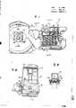
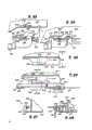
图1是现有技术的摆动转向架部分剖开的侧视图;Figure 1 is a partially cut-away side view of a prior art swing bogie;
图2是沿图1中2-2线,顺箭头指示方向看去,轴承组被拆卸后的纵剖面图;Figure 2 is a longitudinal sectional view of the disassembled bearing group viewed along the line 2-2 in Figure 1 and in the direction indicated by the arrow;
图3是沿图1中3-3线的局部剖开的平面图;Fig. 3 is a partially cut-away plan view along line 3-3 in Fig. 1;
图4是放大的局部侧视图,局部剖开,表示枢轴式支承的摇座的一端;Figure 4 is an enlarged partial side view, partially cut away, showing one end of the pivotally supported rocker;
图5是沿图4中5-5线的局部端视图;Fig. 5 is a partial end view along line 5-5 in Fig. 4;
图6是沿图4中6-6线的局部平面图;Fig. 6 is a partial plan view along line 6-6 in Fig. 4;
图7是沿图1中7-7线的部分剖开的局部端视图;Figure 7 is a partially cutaway partial end view along line 7-7 in Figure 1;
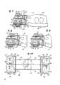
图8和图9与图7类似,表示转向架横向位移的第一和第二阶段中转向架的横向运动。Figures 8 and 9 are similar to Figure 7 and show the lateral movement of the truck during the first and second phases of lateral displacement of the truck.
图10是公路挂车的侧视轮廓图,挂车正准备与牵引车连接以便在公路上运输,根据本发明,该挂车在后部的底部安装有联接装置,可以与铁路转向架上的接合器联接。Figure 10 is a side profile view of a road trailer being prepared to be coupled to a tractor for transport on a road, the trailer being fitted with a coupling at the bottom of the rear according to the invention for coupling with an adapter on a railway bogie .
图11是图10所示挂车的后视图;Figure 11 is a rear view of the trailer shown in Figure 10;
图12是图10和图11所示挂车首尾相接形成列车的侧视图,挂车的公路行走装置被抬起,挂车的尾部由转向架支承;Figure 12 is a side view of the trailer shown in Figure 10 and Figure 11 connected end to end to form a train, the road running device of the trailer is lifted, and the tail of the trailer is supported by a bogie;
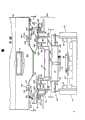
图13是挂车底盘的平面图,为清楚起见,省略了车底板;Figure 13 is a plan view of the trailer chassis, with the floor plate omitted for clarity;
图14是沿图13中14-14线的挂车纵剖视图;Fig. 14 is a longitudinal sectional view of the trailer along line 14-14 in Fig. 13;
图15是沿图12中15-15线的挂车与转向架相连端的正视图;Figure 15 is a front view of the trailer connected to the bogie along line 15-15 in Figure 12;
图16与图15类似,但给出了转向架,接合器两部分和挂车的分解图;Figure 16 is similar to Figure 15 but showing an exploded view of the bogie, the two parts of the adapter and the trailer;
图17是沿图16中17-17线的接合器下部的平面图;Figure 17 is a plan view of the lower part of the adapter along line 17-17 in Figure 16;
图18是沿图16中18-18线的接合器上部的平面图;Figure 18 is a plan view of the upper part of the adapter along line 18-18 in Figure 16;
图19是沿图16中19-19线的挂车后端的底视图;Figure 19 is a bottom view of the rear end of the trailer along line 19-19 in Figure 16;
图20是沿图19中20-20线的剖视图;Fig. 20 is a sectional view along line 20-20 in Fig. 19;
图21是沿图18中21-21线的剖视图;Fig. 21 is a sectional view along line 21-21 in Fig. 18;
图22是沿图18中22-22线的剖视图;Fig. 22 is a sectional view along line 22-22 in Fig. 18;
图23是锁紧装置分解侧视图,锁紧装置用于把接合器锁紧在挂 车上,图中所示的锁紧装置处于未锁紧状态;Figure 23 is an exploded side view of the locking device, which is used to lock the adapter on the hanger On the car, the locking device shown in the figure is in an unlocked state;
图24是图23所示锁紧装置处于锁紧状态时的侧视图;Fig. 24 is a side view when the locking device shown in Fig. 23 is in a locked state;
图25是锁紧装置位于挂车垂直后端的部分的平面图;Figure 25 is a plan view of the portion of the locking device located at the vertical rear end of the trailer;
图26是图24所示锁紧装置的平面图;Figure 26 is a plan view of the locking device shown in Figure 24;
图27是沿图25中27-27线的剖视图,是锁紧装置在挂车尾部的部分的侧视图;Figure 27 is a sectional view along line 27-27 in Figure 25, which is a side view of the part of the locking device at the rear of the trailer;
图28是沿图26中28-28线的剖视图;Fig. 28 is a sectional view along line 28-28 in Fig. 26;
图29是沿图18中29-29线的剖视图;Fig. 29 is a sectional view along line 29-29 in Fig. 18;
图30是垂直销子的放大视图;承梁和接合器绕该销子可相对转动,图中螺杆机构用于升高或降低接合器;Figure 30 is an enlarged view of the vertical pin; the bolster and the adapter are relatively rotatable about the pin, and the screw mechanism is used to raise or lower the adapter;
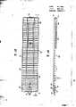
图31是一条线图,表示在不同轨道车上的挂车车身在加速时测出的摆动开始及完全摆动的速度;Figure 31 is a line graph showing the velocity of the onset of oscillation and the velocity of full oscillation measured during acceleration of the trailer body on various railcars;
图32是一条线图,表示与图31相同转向架由于车轮横向力产生的摆动开始及完全摆动时的速度。Fig. 32 is a graph showing the speeds at the start of the bogie swing and at full swing due to the wheel lateral force of the same bogie as in Fig. 31.
图1至图9表示现有技术中的摆动式转向架。转向架10有一具有受拉件21和受压件22的侧架20。两件在23处合并,形成轴箱切口24,可摇动地容纳接合器25和轮轴总成27的轴承组26,板18被插放于轴箱切口24和接合器25之间。接合器25的顶部在25a处有凸形顶冠,并与板18的凸曲的下面18a接合,以便能使侧架相对于接合器和轮轴总成做摆动。侧架长度方向的中部,安装有一对间隔开的立柱28-28,它们与受拉件和受压件相连,形成并部分限定了承梁容纳开口29。开口29容纳承梁30的一端,承梁纵轴横切于侧架的长度方向。不言而喻,虽然,图中只 画出一个侧架,但是,转向架的另一侧也有相同的侧架,以同样方法与转向架的承梁和其它部件配合工作。Figures 1 to 9 illustrate prior art oscillating bogies. The bogie 10 has a side frame 20 having a
受拉件21包括一个部分地容纳摇座32的U形底部31。摇座由一个长形平台33和一个整体式倒T形加固件34组成。摇座的两端各有一个耳轴35,以支承摇座使其可相对侧架摇动。耳轴35-35被支承在一对纵向间隔开的摇动轴承36上,摇动轴承36安置于立柱28-28之下,并与受拉件21的底部31共轴。每个摇动轴承36有一个凹进的圆柱形支承面37,它的曲率半径大于装在其中的耳轴35的曲率半径,以便能使耳轴与支承面之间产生摇动。摇座32有一个顶面38,用以支承簧板40的槽形未端,簧板的纵轴横过侧架的长度方向,簧板40通过摇座上的凸台41与摇座32相连,凸台41通过簧板上的开口把两侧架连结在一起。弹簧组42放置在簧板40和承梁30之间以便实现承梁端的弹性支承。The
图1和图2所示承梁的每端基本是箱形结构,包括两个隔离开的垂直侧壁45-45,隔开的顶面46和底面47以及连接顶面和底面的垂直的中间壁48。一止动凸块50从承梁每端向内伸出,与簧板40上的凸台51之间有一段间隔,止动凸块50和凸台51隔开预定的距离以便其相对的表面间具有一个大约 5/8 英寸的间隙,该间隙使承梁可以进行有限的横向运动。可以看出,每个止动凸块和凸台的接合将出现在接合器25和轴箱切口24限定的摇动连接的水平面之下的高度上,该摇动连接可以为美国专利2,717,588号所公开的类型,也可以是美国专2,737,907号所公开的类型。这种连接形式通常使转向架的侧架可以在转向架的横向进行摆 动。Each end of the bolster shown in Figures 1 and 2 is a substantially box-shaped structure comprising two spaced apart vertical side walls 45-45, spaced top 46 and bottom 47 sides and a vertical middle connecting the top and bottom sides. Wall 48. A
为了抑制转向架的缓冲质量,承梁的各端有一个凹槽55,开口朝向毗邻的立柱28来容纳摩擦闸瓦56。每个凹槽都有一个倾斜的后壁57,它向上并向外朝向毗邻的立柱28倾斜。每一摩擦闸瓦楔入接合于后壁57和相对的立柱28之间。每一闸瓦有一斜面58,与后壁57上的平面60接合,并有一垂直摩擦面59,与固定在毗邻立柱上的防磨板62的表面61相接合。当摩擦闸瓦工作时,受到安装在簧板40上的弹簧63的力,向上、向外与防磨板的表面61摩擦接合,产生了对承梁垂直和横向运动的阻力。To dampen the cushioning mass of the truck, each end of the bolster has a recess 55 opening towards the
转向架各部分结构的设置使侧架能协调地横向摆动。侧架无论朝哪个方向摆动都因摇座台33的下表面65和受拉件的底部31的侧壁67-67之一的顶面66接触而受阻停止。如图7所示,这两个接合面之间的间隙可以使侧架从中间位置横向地向两侧摆动约3度。这一摆动造成承梁横向摆动约5/8英寸。负载弹簧的横向偏转还可使承梁做附加的5/8英寸的横向摆动。空载与满载货车厢的特点是不同的,因为对横向摆动的阻力取决于承梁的负载,这样,对横向摆动的阻力与垂直负载成正比,因而任何部分的负载将产生一个介于空载车厢与满载车厢之间的对横向摆动的阻力值。The structural arrangement of each part of the bogie enables the side frame to swing laterally in a coordinated manner. No matter which direction the side frame swings, it is hindered and stopped due to the contact of the lower surface 65 of the rocker platform 33 and the top surface 66 of one of the side walls 67-67 of the bottom 31 of the tension member. As shown in FIG. 7, the gap between these two joint surfaces allows the side frame to swing laterally to each side about 3 degrees from the neutral position. This swing caused the bolster to swing laterally about 5/8 inch. Lateral deflection of the load springs also allows an additional 5/8 inch of lateral play of the bolster. The characteristics of an empty and fully loaded freight car are different, because the resistance to lateral oscillation depends on the load on the bolster, so that the resistance to lateral oscillation is proportional to the vertical load, so that any part of the load will produce a load between the unloaded Resistance to lateral swing between a car and a fully loaded car.
如图8所示,在横向摆动的第一阶段,对侧架摆动的阻力受三个控制因素的影响:(1)摆动吊架的长度,即,轴箱切口24和接合器25的接合部分与摇动轴承36和耳轴35的接合部分之间的垂直距离;(2)作用在车身和侧架20上的正常重力;(3)对负载弹簧组42横向扭曲的阻力。这些控制因素共同按串联方式产生低阻 力。当侧架的摆动由于摇座32与受拉件21的接合而停止后,承梁的剩余摆动可以由负载弹簧组42的偏转而获得,这就引起横向摆动的第二或高阻力阶段(见图9)。As shown in Figure 8, during the first stage of lateral swing, the resistance to sideframe swing is affected by three controlling factors: (1) the length of the swing hanger, i.e., the joint portion of the
根据振动理论,向摆施加横向力时,摆的横向位移与所加的力成正比,这与弹簧受垂直力伸缩时的特点类似,它的偏转与施加的力成正比。因此,一个弹簧的理论刚性系数可以被摆的横向力一位移特性所替代。这就是说,由于侧架起到了一个摆动吊架即摆的作用,并因负载弹簧42横向变形,作同向的横向运动,所以侧架的横向摆动就具有了有效弹簧刚性系数。况且,螺旋弹簧除了其垂直的力一位移特性外还有横向力一位移特性。因此,弹簧组42的横向偏转以及摆动吊架的横向偏转可以被认为是两个弹簧的串联动作。众所周知,当两个弹簧串联动作时,得出的弹簧刚性系数K比两个弹簧中任何一个的弹簧刚性系数K都低。这样,基本上低阻力是受下述公式支配的:Kc=(K1K2)/(K1+K2),其中K1是侧架摆动的有效弹簧刚性系数,K2是负载弹簧组42横向弹簧刚性系数,Kc是得出的复合弹簧刚性系数,它限定承梁相对于侧架的横向摆动的阻力。在侧架摆动预定量后,这种摆动即停止,而承梁相对于侧架的剩余横向摆动只是反抗负载弹簧组42的横向阻力进行,如前所述,负载弹簧组42具有比第一阶段强得多的弹簧刚性系数。这种转向架提供了相对于铁路中心线每侧的适度的横向摆动,其总量约为1 1/4 英寸。而且这种转向架把以下两种特性结合起来,即:(1)为防止非控制的摆动,对承梁相对于侧架的正常横向摆动的低阻力特性,以及(2)为防止承梁止动器与侧架的相关部件的剧烈横向接 触,对承梁过度的横向运动的高阻力特性。According to the vibration theory, when a lateral force is applied to the pendulum, the lateral displacement of the pendulum is proportional to the applied force, which is similar to the characteristics of a spring when it is stretched by a vertical force, and its deflection is proportional to the applied force. Therefore, the theoretical stiffness coefficient of a spring can be replaced by the lateral force-displacement characteristic of the pendulum. That is to say, since the side frame acts as a swing hanger, that is, pendulum, and due to the lateral deformation of the load spring 42, it moves laterally in the same direction, so the lateral swing of the side frame has an effective spring stiffness coefficient. Moreover, coil springs have lateral force-displacement characteristics in addition to their vertical force-displacement characteristics. Thus, the lateral deflection of the spring set 42 and the lateral deflection of the swing hanger can be considered as a series action of the two springs. It is well known that when two springs act in series, the resulting spring rate K is lower than that of either spring. Thus, basically low drag is governed by the following formula: Kc = (K1 K2 )/(K1 +K2 ), where K1 is the effective spring rate of sideframe swing and K2 is the load spring Group 42 Lateral Spring Stiffness Coefficient,Kc is the derived composite spring stiffness coefficient that defines the resistance to lateral oscillation of the bolster relative to the sideframe. After the side frame swings by a predetermined amount, this swing stops, and the remaining lateral swing of the bolster relative to the side frame is only carried out against the lateral resistance of the load spring set 42. Much stronger spring rate. This bogie provides moderate lateral play totaling approximately 1 1/4 inches each side of the railroad centerline. Moreover, this bogie combines the following two characteristics, namely: (1) to prevent uncontrolled swing, low resistance characteristics to the normal lateral oscillation of the bolster relative to the side frame, and (2) to prevent the bolster from stopping. Strong lateral contact of the actuator with associated parts of the sideframe, high resistance characteristics to excessive lateral movement of the bolster.
如图10至图12所示,挂车70的车身72的尺寸相当于一个传统的公路半挂车,可长48英尺。车身72在其前端有阳连接件74,在其尾端有一阴连接件76,用以承接相邻车身的阳连接件(见图12)从而组成列车,进行铁路运输。本说明书引用美国专利第4,202,454号的全部内容作为参考文献,该专利详细公开了这种连接装置。每节挂车70具有一个靠近车身前端的传统的拖钩销78,在公路运输时可以与牵引车的支座轮可卸式接合,还包括按常规安装的挂车的伸缩式升降机构80,以及公路行走机构81,公路行走机构81又具有括串列轮轴82(不过也可以采用单轴或三轴悬挂),每个轴装有橡胶轮胎车轮84。行走机构81装在车身72的底盘86上的构件88上,可向车身后部滑动。行走机构81采用了可使其升降的气垫吊架。挂车尾端的底部安装有第一联接装置90,它是挂车车身的整体的和固定的部分。第一联接装置90能与固定在前述转向架10上的第二联接装置100可卸式接合。适当操作气动装置,将使公路用轮悬空的气垫冲气,从而可使公路用轮84降低,与地面接触,这样公路行走机构81即在公路行驶时支承挂车。当挂车升降机构80处于负载支承位置时(见图10),传统的牵引车联接于拖钩销78,挂车升降机构80则处于抬高位置,车辆便为进行公路运输做好了准备。As shown in FIGS. 10 to 12 , the
进行铁路运输时需把挂车(挂车处于前述公路运输方式)倒车至一辆在铁轨上的转向架附近并与该轨道车对准。适当操作气动装置,把悬置公路用轮的气垫临时过分充气,使挂车车身略高于正常行驶高度,这样挂车便可支承于转向架上,与转向架10的第二联接装置 100接合。进一步操作气动装置,泄掉悬置公路用轮的气垫中的气,车轮便退回至备用的和升高的非工作位置(见图10),这样,挂车车身的后部重量即由转向架所支承。然后,随后的一节挂车的前端与转向架所支承的挂车的尾部相联接。如此反复操作,组装成列车。Rail transport involves reversing the trailer (with the trailer in the aforementioned road transport mode) near a bogie on the rails and aligning it with the rail car. Properly operate the pneumatic device to temporarily inflate the air cushion for suspending road wheels, so that the trailer body is slightly higher than the normal driving height, so that the trailer can be supported on the bogie, and the second coupling device with the bogie 10 100 engagements. The pneumatic device is further operated to release the air in the air cushion for suspending the road wheels, and the wheels return to the standby and raised non-working positions (see Figure 10), so that the rear weight of the trailer body is carried by the bogie. support. The front end of the following trailer is then coupled to the rear of the trailer supported by the bogie. So repeated operation, assembled into a train.
下面说明的可卸式锁紧装置,把转向架上的第二联接装置锁紧并固定在挂车车身上的第一联接装置上。在铁路运输方式中,如前所述,相似的挂车可以首尾相接组成列车;由合适的火车头牵引。The detachable locking device described below locks and fixes the second coupling device on the bogie to the first coupling device on the trailer body. In the rail mode of transport, similar trailers may be joined end to end to form trains, as previously mentioned; drawn by suitable locomotives.
使挂车从铁路运输方式转换到公路运输方式可按上述相反的程序操作。一辆公路牵引车首先与拖钩销78联接,再使转向架与挂车脱开,操作气动装置把悬置公路用轮的气垫暂时过度充气,降低公路用轮,使其与地面接触,挂车车身被抬至略高于正常行驶高度,从而使挂车脱离转向架。这样挂车便可与牵引车结合而被牵引行驶。Converting a trailer from rail to road transport can be done in reverse of the procedure above. A road tractor is first connected with the tow hook pin 78, and then the bogie is disengaged from the trailer, and the air cushion for suspending the road wheels is temporarily over-inflated by operating the pneumatic device, and the road wheels are lowered so that they are in contact with the ground. Lifted to slightly above normal ride height, allowing the trailer to disengage from the bogie. In this way, the trailer can be combined with the tractor to be towed.
参见图13和图14,挂车的前端附近有一个传统的半挂车拖钩销辅助架91,它与挂车同宽,固定在车身两侧梁92之间,并向后伸入挂车之内,它的一种典型的结构是由上板93和下板94组成,上、下板由横向连接板95连接在一起,实际上形成一个箱形梁,铁路运输时用的阳联接件74与拖钩销辅助架为一整体结构。在挂车尾端有一个底架结构96,与车身同宽。Referring to Fig. 13 and Fig. 14, there is a traditional semi-trailer tow hook pin auxiliary frame 91 near the front end of the trailer. A kind of typical structure is made up of upper plate 93 and lower plate 94, and upper and lower plate is connected together by transverse connecting plate 95, actually forms a box beam, and male connector 74 and tow hook used during railway transportation The pin auxiliary frame is an integral structure. There is an underframe structure 96 at the rear end of the trailer, which is as wide as the vehicle body.
在拖钩销辅助架91的后端与尾部底架96的前端之间有许多I形横梁97,它们的两端固定在车身两侧梁92上,行走机构导梁88固定在其中一些I形横梁上。沿挂车身纵向,在横梁97之上有底板(图中未画出),底板最好由硬木胶合板制成,并将其邻接边缘 磨成可以进行搭接或其他合适的连接形式。There are many I-shaped beams 97 between the rear end of the towing hook pin auxiliary frame 91 and the front end of the tail chassis 96, and their two ends are fixed on the body side beams 92, and the running
前述结构能通过挂车传递很大的缓冲力和牵引力,特别是当挂车连接起来,在铁路上行驶时(如图12),它无需一般铁路运输设备中普通使用的重型中梁结构。挂车遇到的上述力要比常规公路挂车大,但比货车厢遇到的要小,这是因为消除了列车各节之间的间隙。The aforementioned structure can transmit a large buffering force and traction force through the trailer, especially when the trailers are connected and run on the railway (as shown in Figure 12), it does not need the heavy-duty center beam structure commonly used in general railway transportation equipment. The aforementioned forces encountered by trailers are greater than those encountered by conventional road trailers, but less than those experienced by freight cars, due to the elimination of gaps between the train sections.
下面详细说明第一联接装置和第二联接装置,或接合器。The first and second coupling means, or adapters, are described in detail below.
不论组成公路挂车列车时是采用何种转向架,都要求具有联接装置,可以把转向架可卸式地联接在每节挂车的尾端。本发明的联接装置包括一个固定在挂车底部的第一联接装置和一个固定在转向架上,并且可以与第一联接装置接合的第二联接装置。为减轻公路运输中挂车承受的重量,第一联接装置被设计得尽量轻。因此,联接装置所要求的大部分重量安排在固定于转向架上的第二联接装置中。但是,不言而喻,第二联接装置的重量不应超过其功能的需要。No matter what kind of bogie is used to form a road trailer train, it is required to have a coupling device that can detachably connect the bogie to the tail end of each trailer. The hitch of the present invention comprises a first hitch fixed to the bottom of the trailer and a second hitch fixed to the bogie and engageable with the first hitch. In order to reduce the weight borne by the trailer in road transport, the first coupling device is designed to be as light as possible. Consequently, most of the weight required by the coupling is arranged in the second coupling fixed to the bogie. It goes without saying, however, that the weight of the second coupling device should not exceed its functional requirements.
图15至图21给出了装于挂车车身尾端底部的第一联接装置和装于转向架10上的第二联接装置100。为方便起见,在说明第一联接装置之前,首先详细说明第二联接装置100。15 to 21 show the first coupling device mounted on the bottom of the rear end of the trailer body and the
如图15至21所示形式的第二联接装置100具有一个把转向架10联接到挂车上的接合器,固此,接合器与第二联接装置都用相同的标号100。A
接合器或第二联接装置100(如图15和图16所示),具有下部102和上部152,它们在承梁30纵向上大体呈水平安装。承梁30中部有一个中心盘槽68和一对按通常位置装配的侧轴承69。The adapter or second coupling device 100 (shown in FIGS. 15 and 16 ) has a
接合器的下部102(见图16、17),有一中心部分104和两个互为镜像的端部106、108,装在中心部分的两端。中心部分104有相对的垂直侧板110,112,顶板114和具有轴承凸台118的底板116,轴承凸台118装配在承梁中心盘槽68中,以便当列车沿铁轨行驶时它们可以绕同一竖轴转动。The
两个端部106,108,各有一个与中心部分104的一端相连的端壁120,一对侧壁122,124以及一垂直中心撑板126。水平安装的三角形角撑板128加固了壁120、122、124和板126。每个端壁120的顶部装有一个水平的长形弹簧挡板130。底板132连接于壁120、122、124和板126的底边。一对相互分隔开的,朝上伸出的短销134装在每个底板132的上表面上。接合器包括一个辅助悬挂装置,由一对圆柱形弹性件136组成,弹性件上有一垂直的轴向孔,每一端部106、108上都装有一对弹性件136,并有一短销134伸入每个孔的下部,从而防止弹性件136的水平滑动(见图17、20和21)。弹性件136起弹簧的作用,当在接合器的上部152加载时,弹性件136被压缩,这一点后面还将详细说明。Each end portion 106,108 has an
当轴承凸台118在中心盘槽68中处于工作位置时,端部106、108的底面支承在相邻的侧轴承69上。一个垂直销140安装在中心部分104的中心和轴承凸台118的中心(见图18、29和30)。销140的上端有一轴向螺孔,螺钉141被旋入该螺孔。板114之下,螺钉141上装有一套环142。螺钉141顶端有一方形或六角形头143,以便用扳手把整个接合器 100向上旋离轴承凸台118和侧轴承69。销140的下端144固定在承梁中,使该销子不能转动。当接合器这样地被向上旋起时,可以容易地用手将其转动180°。反向转动螺钉141便可降低接合器,以便轴承凸台118座入中心盘槽68中,而且接合器也被侧轴承69所支承。这一操作可以使挂车从转向架任一端与接合器连接时,而不必转动整个转向架。The bottom surfaces of the
接合器的上部152(见图16和图18)有一对互成镜像的隔开的端部154、156,由一对隔开的平行梁158、160相连接。每一端部154、156都有前、后壁166、168和顶板170。壁166、168装有隔开的垂直支撑板169。一加强板172从顶板170底部向下伸出,另一垂直板174也从顶板170底部向下伸出,在板174下缘有一水平板176。与撑板178加固这些板。水平板176在板130之上与其有一定间隔,但与其共同组成一个止动装置,将圆柱形弹性体136的压缩限制在两个板之间。不言而喻,圆柱形弹性件136在接合器中处于一定的初始预压缩状态。顶板170的底部也有短销178,配合在圆柱形弹性件136中的轴向孔中,以防止圆柱形弹性件136的水平移动。The
如图15所示,接合器上部152装在接合器下部102之上,四个圆柱形弹性件由短销134、178定位,从而形成接合器100。接合器上部152朝接合器下部102挤压圆柱形弹性件136。当接合器上下两部分102,152照此安装时,相应的端部106、154和108、156组成一个空间,圆柱形弹性件136装在其中。钩子180置于壁166、168上的三个支撑板 169的中间支撑板上。钩子180被调整,固定好位置,与下部102的板132的底面相接触。这样,圆柱形弹性件136得到一个轻的压力,但并不限制其进一步受压。随着上部152所承受负荷的增加,圆柱形弹性体136将被压缩直至止动板176与板130相碰。一般来说,当最大负荷的1/2加在接合器上时,这两板相碰,这在下面还要详述。在梁160上装有止动桩177,可趋近接合器下部102的板120,以便把接合器上部152与接合器下部102之间的双向横向运动限制在预定的距离之内。As shown in FIG. 15 , the
顶板107的每条外边都向内朝转向架10的纵向中心线有一个倒角,以引导接合器进入挂车尾端的底面之下的正确位置(见图18)。一对有类似倒角的零件200(见图16、19和21)装在挂车车身底面上。每一零件200构成有一定角度长板,并有一垂直上部202和一向外倾斜的下部204。支撑板206加强,每一零件200以防变形。Each outer edge of the top plate 107 is chamfered inwardly towards the longitudinal centerline of the truck 10 to guide the adapter into the correct position under the underside of the trailer end (see Figure 18). A pair of similarly chamfered parts 200 (see Figures 16, 19 and 21) are attached to the underside of the trailer body. Each
如图15和图18所示,当接合器100位于一挂车之下时,顶板170和它所接触的挂车的两个隔开的底部210之间的摩擦提供了把它们接合在一起的主要的力。如图12所示,挂车是首尾相接的,所以对接合器或转向架没有牵引力或缓冲力,但是,转向架是随同挂车一起被牵引的。只有当列车制动时,才在转向架与挂车之间有一个值得注意的纵向差动力。这个力很容易被顶板170与挂车底部210之间的摩擦力所克服。尽管如此,还是安装了锁紧装置牢固地地、可卸式地将接合器锁紧在挂车上。As shown in Figures 15 and 18, when the
接合器上部152的每一端部154、156都装有锁紧机构 211、212,它们互为镜像(见图15,16,19,20和图23至28)。每一锁紧机构211、212包括一个L形手柄214,通过销子216与板166前端的托架218相连。锁紧杆220通过销222枢轴地与手柄214相连接。锁紧杆220的一头有一槽224,一固定销226装在该槽中。销226固定在板166中。在锁紧杆220的顶端装有板228。沿板228底部的一边有一个杆230,沿板228底部的对边也有一个杆232,以限制锁紧机构在锁紧时相对于接合器上部152和挂车车身垂直后端270的水平运动。Each
挂车的垂直后端270有两个锁紧机构240(见图23至28),它们互为镜像。每一锁紧机构240可以和接合器100上的锁紧机构211、212锁紧。每一锁紧机构240包括一个位于挂车车身底210后缘外的垂直板242。垂直板242的支承挂车垂直后端270上的水平板244,垂直板246横切于板242,并伸至挂车后端270。板246也安在挂车底部210上并支承水平板244。The vertical
图23描绘的是锁紧机构处于脱开位置,手柄朝上。在此位置,转向架与接合器都位于挂车之下,然后,下移手柄至图24所示位置,将其锁紧。在此位置,接合器上的锁紧机构与挂车接合(见图28),从而防止挂车相对于接合器前后移动,因为杆232的一部分处于板244之下,也可防止挂车向上移动而脱离接合器。向上提起手柄214至垂直位置便可打开锁紧机构。当挂车略被抬起后,转向架和接合器可以从挂车之下脱离出来。Figure 23 depicts the locking mechanism in the disengaged position with the handle facing upwards. In this position, both the bogie and the adapter are under the trailer, then, move the handle down to the position shown in Figure 24 to lock it. In this position, the locking mechanism on the adapter engages the trailer (see Figure 28), thereby preventing the trailer from moving fore and aft relative to the adapter, as part of the
关于装有辅助悬挂装置的接合器和摆动式转向架的协同动作,下面将进一步加以说明,并介绍其特殊的结构特点。The cooperative action of the adapter equipped with the auxiliary suspension device and the swing bogie will be further explained below, and its special structural features will be introduced.
在接合器100中最好使用圆柱形弹性件136,具体地说在侧轴承之上的每侧各设置二件。圆柱形弹性件的作用如同弹簧,这些弹性件把空车负载传递到转向架上,与止动件176的间隙大约为0.75英寸。当挂车空载时,弹性件的弹簧作用减弱路轨引起的垂直和横向振动及谐和负荷。无需辅助的减振装置,这是因为:(1)圆柱形弹性件136使部分能量自然耗散,(2)空载挂车的重心低,(3)相对于重心高度而言,弹簧间距和弹簧刚度产生的横摇稳定性高。至少对某些无阻尼弹性起作用的能力大大减少可以传递的振动频带宽度。因此,例如一个传统的货车厢悬挂装置及一轻型车厢可以在任何频率下传递0.5G,而本发明的挂车只能够在其自己的自然频率附近传递较窄的频带宽度。这就使运动定律发挥作用,减弱振源。Cylindrical
接合器辅助悬挂装置为转向架轴及轻载或空载挂车提供一个使其稳定的效应,这增加了开始出现摆动的速度。其原因是驱使车轴摆动的那部分能量是车身反馈的结果。这一反馈由圆柱形弹性件缓解,这就是稳定效应的部分原因,但主要原因是,车身自然频率被降低,它对车轴振动自然频率的比率变得较低,这反过来又降低了反馈的传递。仅关于摆动而言,挂车车身的横向自然频率似乎不能降得太低。The coupler-assisted suspension provides a stabilizing effect on the bogie axle and lightly or empty trailer, which increases the speed at which oscillation begins to occur. The reason for this is that the portion of the energy that drives the axle to wobble is a result of body feedback. This feedback is mitigated by the cylindrical elastic, which is partly responsible for the stabilizing effect, but mainly because, the natural frequency of the body is lowered, its ratio to the natural frequency of the axle vibration becomes lower, which in turn reduces the feedback transfer. As far as the oscillation is concerned only, it seems that the lateral natural frequency of the trailer body cannot be reduced too low.
辅助悬挂装置即圆柱形弹性件也保护空载挂车车身。虽然在半载或满载的挂车上,辅助悬挂装置的一个目的是保护车辆设备,然而辅助悬挂装置也可以特别适于某种有效载荷,从而带来很大好处。车辆 设备的结构使得,当挂车空载直至装载到(例如)6.5吨的范围中,借助悬挂装置即圆柱形弹性件与转向架螺形弹簧完全以串联方式一同工作,超过该载荷后,便碰到止动件176,把所有增加的负荷平行地传递到圆柱形弹性件。这个效果应该在空载和最大载荷时产生几乎恒定的自然频率,而以中等载荷时的频率为最大。当止动件176刚性接触时,圆柱形弹性件对振动无影响,但是对于消除轨道扭曲的影响却能发挥很大作用。因此,挂车可以应付严重的轨道扭曲,在挂车接合处产生较小的扭转应力,这是因为止动件176可以通过圆柱形弹性件卸载,从而应付这种不正常的情况。这个特点使挂车很能适应不平稳的轨道。整个的车轮卸载变得很不可能,因为车轮卸载的有效弹簧行程大约为普通货车的两倍。6.5吨载荷的止动位置可认为是基于合理载荷的折衷点。如果有下列几种情况,出于摇摆的考虑,在整个载荷范围内可以使圆柱形弹性件发挥效力:(1)装载的载荷重心低,(2)沿途无摇摆的轨道,(3)如有摇摆轨道,不以谐振速度驶过,或者(4)为辅助悬挂装置提供外部减振。The auxiliary suspension, ie the cylindrical spring element, also protects the unladen trailer body. While one purpose of an auxiliary hitch on a semi- or fully loaded trailer is to protect vehicle equipment, an auxiliary hitch can also be tailored to a particular payload to great benefit. vehicle The structure of the equipment is such that when the trailer is unloaded until it is loaded in the range of (for example) 6.5 tons, by means of the suspension device, that is, the cylindrical elastic member and the bogie coil spring work together in series, and after exceeding this load, it hits The
摆动式转向架最好每辆装有8个在外面的D7和8个在里面的D4螺形弹簧,并与四个外部楔弹簧平行。每个转向架的螺形弹簧可以附设有4个TecsPak缓冲器(W·H·Miner Dir of Miner Enterprises,Inc Geneva Ill),它们在螺形弹簧量大压缩高度之上0.5英寸处开始接触。缓冲器的目的是降低弹簧最大压缩冲击载荷,例如,从理论上讲,一典型的3.0G的加速度可以减至0.3G。长行程弹簧和缓冲器的结合可能为标准货车硬件提供最轻的悬挂。当挂车空载或装载 量不到6.5吨时,一般来说,行驶颠簸性能优于任何其它货车,这是因为转向架的主悬挂弹簧和接合器的辅助弹簧串联起作用。从载荷6.5吨至满载,行驶颠簸性能起码相当于装有D7弹簧的标准货车,而一般来说,优于装有任何其它种类的螺形弹簧的货车,但是对各种载荷情况,由于有了缓冲器,将出现通常的弹簧最大压缩冲击。The swing bogies are preferably equipped with 8 outer D7 and 8 inner D4 coil springs each, parallel to the four outer wedge springs. Each bogie coil spring can be attached with 4 TecsPak bumpers (W.H. Miner Dir of Miner Enterprises, Inc Geneva Ill) that begin contact at 0.5 inches above the maximum compression height of the coil spring. The purpose of the buffer is to reduce the maximum spring compression shock load, for example, theoretically speaking, a typical acceleration of 3.0G can be reduced to 0.3G. A combination of long-travel springs and bumpers provides the lightest suspension possible for standard van hardware. When the trailer is empty or loaded Generally speaking, the ride is better than any other truck weighing less than 6.5 tons because the main suspension springs of the bogie and the auxiliary springs of the clutch work in series. From a load of 6.5 tons to full load, the running bump performance is at least equivalent to that of a standard truck equipped with D7 springs, and generally speaking, it is better than a truck equipped with any other type of coil springs, but for various load conditions, due to the Shock absorber, the usual spring maximum compression shock will occur.
摆动式转向架的特征是用横梁互相连接的象摆一样动作的侧架。横梁也与转向架侧架互相固定连接以防止平行四边形运动。这种悬挂装置的横向动作协同良好的矩形刚度,使挂车在任何速度下,特别是在高速下,具有极好的横向稳定性,软的横向刚度也大大降低了被传递的横向负荷。摆动加上螺形弹簧的偏转提供了总量为11/4英寸的至固定式止动件的运动量,这就简化了在列车编组时挂车的对准作业。挂车空载时,接合器辅助弹簧与转向架的主弹簧以及摆动的串联动作更进一步改善了行驰颠簸性能。无论在空载或是在装载情况下,总的行驶颠簸性能都可望优于传统的货车。目前的情况表明实际上可以达到每小时85英里。按照本发明的公路挂车列车在货运竞争中成功的关键因素是横向摆动性能加上速度指标的综合效果。Oscillating bogies are characterized by pendulum-like sideframes interconnected by beams. The beams are also fixedly connected to the bogie sideframes to prevent parallelogram motion. The lateral action of this suspension device cooperates with the good rectangular stiffness, so that the trailer has excellent lateral stability at any speed, especially at high speeds, and the soft lateral stiffness also greatly reduces the transmitted lateral load. Oscillation plus coil spring deflection provides a total of 1 1/4 inches of movement to the fixed stops, which simplifies trailer alignment during train formation. When the trailer is unloaded, the tandem action of the auxiliary spring of the adapter with the main spring of the bogie and the swing further improves the running bump performance. Overall ride roughness is expected to be better than that of conventional trucks, whether unladen or loaded. Current conditions suggest that 85 miles per hour can actually be achieved. The key factor for the success of the road trailer train according to the invention in the freight competition is the combined effect of the yaw performance plus the speed index.
图31和图32表明,按照本发明的,装备有摆动式转向架和接合器的挂车列车的优良性能。Figures 31 and 32 illustrate the superior performance of a trailer train equipped with an oscillating bogie and coupler according to the present invention.
图31表明摆动开始(虚线)和充分摆动(条柱顶线)出现时的速度。该图是用电子计算机模型研究分析以下五种转向架的结果:Figure 31 shows the speed at which the swing begins (dotted line) and when full swing occurs (bar top line). This figure is the result of studying and analyzing the following five types of bogies with an electronic computer model:
A.国家CI标准三件式货运转向架。(National CI Standand three-pieces freighttrack)A. National CI standard three-piece freight bogie. (National CI Stand and three-pieces freighttrack)
B.AsF Ridemaster转向架,条件是它装备有 Standard Car Truck公司出售的框架撑臂(frame brace)B.AsF Ridemaster bogie, provided it is equipped with Frame braces sold by Standard Car Truck
C.与B相同,但挂车车身和转向架之间装有滚柱装置,用以将挂车车身与轨道横向动力载荷隔开。C. Same as B, but a roller device is installed between the trailer body and the bogie to separate the trailer body from the lateral dynamic load of the track.
D.在美国专利3,670,660号中描绘的National Castings摆动式转向架。D. National Castings oscillating truck depicted in U.S. Patent No. 3,670,660.
E.与D相同,但装有本发明的具有4个圆柱形弹性件的接合器,圆柱形弹性件所用材料为纤维加固的橡胶,也起非线性弹簧作用。圆柱形弹性件由Firestone工业公司经销,商标为MARSHMELLOW。E. Same as D, but equipped with the adapter of the present invention with 4 cylindrical elastic parts, the material of the cylindrical elastic parts is fiber-reinforced rubber, which also acts as a nonlinear spring. Cylindrical elastic members are distributed by Firestone Industries under the trademark MARSHMELLOW.
摆动开始速度是车轴或挂车车身开始出现摆动增加时的速度。随着列车速度超过摆动开始速度直至达到周期限制,摆动将继续增加,充分摆动是指达到周期限制上限之后的摆动。周期限制取决于车轮凸缘间隙或挂车车身的能量平衡。在上限摆动期间,即产生了对挂车的破坏力。图31对摆动作了比较,以挂车车身加速度对重力加速度的比值为基础,车身加速度是在直接置于转向架上方的挂车车身内测出的。The swing onset speed is the speed at which the axle or trailer body begins to experience increased swing. As the train speed exceeds the swing start speed until the cycle limit is reached, the swing will continue to increase, full swing refers to the swing after reaching the upper limit of the cycle limit. The cycle limit depends on the wheel flange clearance or the energy balance of the trailer body. During the upper limit swing, the destructive force to the trailer is generated. Figure 31 compares the swing, based on the ratio of the trailer body acceleration to the gravitational acceleration, measured in the trailer body directly above the bogie.
图31表明D的性能优于A、B和C。而且,该图还表明,增设的圆柱形弹性件(E)改善了对摆动的性能。A的峰值加速度为2.1G(每小时70英里),而D的该值被减至0.4G(每小时100英里),E的该值在每小时100英里时被减至0.2G。Figure 31 shows that D outperforms A, B and C. Moreover, the figure also shows that the addition of the cylindrical elastic member (E) improves the performance against swinging. The A has a peak acceleration of 2.1G (70mph), while the D is reduced to 0.4G (100mph) and the E is reduced to 0.2G at 100mph.
图32表示摆动开始及充分摆动出现时速度,测量的尺度为凸缘对铁轨的力除以车轮压在铁轨上的重量的比值,即L/V,L/V是 关系到行车安全的铁路术语,因为当该比值过大时就会发生脱轨。转向架A,B和C具有的该比值均大于1.6,转向架D的该比值约为1.25,而转向架E在每小时90英里的速度下,该比值约为0.25。Figure 32 shows the speed at the beginning of the swing and when the full swing occurs. The measurement scale is the ratio of the force of the flange to the rail divided by the weight of the wheel on the rail, that is, L/V, and L/V is A railway term related to traffic safety, since derailment can occur when this ratio is too large. Bogies A, B and C all have ratios greater than 1.6, bogie D has a ratio of about 1.25, and bogie E has a ratio of about 0.25 at 90 miles per hour.
上述详细说明是为了使人更清楚地理解本发明而作出的,并不应该理解为是对本发明的限定,因为本专业技术人员显然可以对其进行修改而并不超出本发明的实质和范围。The above detailed description is made to make people understand the present invention more clearly, and should not be construed as a limitation of the present invention, because those skilled in the art can obviously modify it without departing from the spirit and scope of the present invention.
Claims (9)
Applications Claiming Priority (2)
| Application Number | Priority Date | Filing Date | Title |
|---|---|---|---|
| US06/920,759US4773335A (en) | 1986-10-20 | 1986-10-20 | Train of highway trailers using improved railroad truck suspension |
| US920,759 | 1986-10-20 |
Publications (2)
| Publication Number | Publication Date |
|---|---|
| CN87106981A CN87106981A (en) | 1988-06-01 |
| CN1008990Btrue CN1008990B (en) | 1990-08-01 |
Family
ID=25444343
Family Applications (1)
| Application Number | Title | Priority Date | Filing Date |
|---|---|---|---|
| CN87106981AExpiredCN1008990B (en) | 1986-10-20 | 1987-10-19 | The adapter that the highway trailer train is used |
Country Status (13)
| Country | Link |
|---|---|
| US (1) | US4773335A (en) |
| EP (1) | EP0264731B1 (en) |
| CN (1) | CN1008990B (en) |
| AT (1) | ATE83989T1 (en) |
| AU (1) | AU602719B2 (en) |
| BR (1) | BR8705523A (en) |
| CA (1) | CA1304987C (en) |
| DE (1) | DE3783308T2 (en) |
| ES (1) | ES2036554T3 (en) |
| IN (1) | IN170215B (en) |
| MX (1) | MX160877A (en) |
| NZ (1) | NZ221815A (en) |
| ZA (1) | ZA876484B (en) |
Cited By (3)
| Publication number | Priority date | Publication date | Assignee | Title |
|---|---|---|---|---|
| CN1070791C (en)* | 1995-08-10 | 2001-09-12 | 标准汽车公司 | Dual face friction wedge |
| CN100383003C (en)* | 2005-07-01 | 2008-04-23 | 李孝龙 | Low-floor high-speed train |
| CN100422020C (en)* | 2004-08-27 | 2008-10-01 | 阿尔斯通运输股份有限公司 | Articulated railway train |
Families Citing this family (37)
| Publication number | Priority date | Publication date | Assignee | Title |
|---|---|---|---|---|
| CA1318551C (en)* | 1988-03-15 | 1993-06-01 | Jacques Viens | Motorized unit for driving a train on rails |
| US5107772A (en)* | 1990-06-22 | 1992-04-28 | Jacques Viens | Rail bogie for transporting semi-trailers with vertically movable king pin assemblies on common frame |
| DE9110120U1 (en)* | 1991-08-16 | 1991-09-26 | Maschinenfabriken Bernard Krone Gmbh, 4441 Spelle | Semi-trailer |
| US5431110A (en)* | 1994-04-28 | 1995-07-11 | Adams, Jr.; George W. | Truck-train system with locking mechanism employing a moment arm |
| US5685228A (en)* | 1995-09-27 | 1997-11-11 | Wabash National Corporation | Bi-tri-level deck system for a railcar |
| AUPN703395A0 (en)* | 1995-12-08 | 1996-01-04 | Sticpewich, John Warren | A device to enable the provision of rail locos or power units which are also load carriers |
| US5746136A (en)* | 1996-09-13 | 1998-05-05 | Amsted Industries Incorporated | Dynamically stable, lightweight railcar support system |
| CA2200769A1 (en) | 1997-03-21 | 1998-09-21 | Jacques Viens | Improved rail bogie and related equipments |
| DE19955390B4 (en)* | 1999-11-18 | 2011-12-08 | Schaeffler Technologies Gmbh & Co. Kg | Rolling bearing connecting ring and mounting tool therefor |
| US7047889B2 (en) | 2000-07-12 | 2006-05-23 | National Steel Car Limited | Rail car with cantilevered articulation |
| US6551039B1 (en) | 2000-09-11 | 2003-04-22 | National Steel Car Limited | Auto rack rail road car with reduced slack |
| US6866295B2 (en)* | 2000-12-28 | 2005-03-15 | Dana Corporation | Modular cast independent front suspension subframe |
| US6895866B2 (en) | 2001-08-01 | 2005-05-24 | National Steel Car Limited | Rail road freight car with damped suspension |
| US7255048B2 (en) | 2001-08-01 | 2007-08-14 | Forbes James W | Rail road car truck with rocking sideframe |
| US7004079B2 (en) | 2001-08-01 | 2006-02-28 | National Steel Car Limited | Rail road car and truck therefor |
| US6659016B2 (en) | 2001-08-01 | 2003-12-09 | National Steel Car Limited | Rail road freight car with resilient suspension |
| US6874426B2 (en) | 2002-08-01 | 2005-04-05 | National Steel Car Limited | Rail road car truck with bearing adapter and method |
| BRPI0411955B1 (en) | 2003-07-08 | 2013-07-23 | auto steering device, interface assembly, railcar wrench and resilient cushion | |
| US7823513B2 (en) | 2003-07-08 | 2010-11-02 | National Steel Car Limited | Rail road car truck |
| US7422413B2 (en)* | 2005-06-15 | 2008-09-09 | Florida Turbine Technologies, Inc. | Shroud tip clearance control ring |
| US7681506B2 (en) | 2005-06-16 | 2010-03-23 | National Steel Car Limited | Truck bolster |
| US20070024017A1 (en)* | 2005-07-29 | 2007-02-01 | Hendrickson Usa, L.L.C. | Locking mechanism for movable subframe of tractor-trailers |
| CN100386233C (en)* | 2006-05-29 | 2008-05-07 | 郑州大方桥梁机械有限公司 | Independent Steering Suspension Mechanism of Large Power Flatbed Transporter |
| US7704025B2 (en)* | 2006-07-17 | 2010-04-27 | American Railcar Industries, Inc. | Apparatus and method for supporting a semi-trailer on a railcar |
| US9216450B2 (en)* | 2011-05-17 | 2015-12-22 | Nevis Industries Llc | Side frame and bolster for a railway truck and method for manufacturing same |
| CN104859389B (en)* | 2015-06-01 | 2017-10-24 | 赵志贤 | A kind of motor turning frame |
| CN105501011B (en)* | 2015-12-22 | 2017-10-10 | 常州市瑞泰工程机械有限公司 | Road rail vehicle railway running gear |
| CN105501244B (en)* | 2015-12-24 | 2017-12-29 | 北京世纪东方通讯设备有限公司 | A kind of suspension arrangement for row tail |
| CN106394680B (en)* | 2016-11-10 | 2019-01-01 | 中车长江车辆有限公司 | Combined vehicle carriage |
| CN106394681B (en)* | 2016-11-10 | 2018-06-29 | 中车长江车辆有限公司 | Road rail vehicle |
| CN108909841B (en)* | 2018-07-27 | 2024-01-19 | 中车长江车辆有限公司 | Frame and highway and railway dual-purpose vehicle |
| CN109278789B (en)* | 2018-11-21 | 2024-02-23 | 中车眉山车辆有限公司 | Dual-purpose freight car of public iron of semitrailer |
| RU2706677C1 (en)* | 2018-11-28 | 2019-11-19 | Акционерное общество "Рузаевский завод химического машиностроения" (АО "Рузхиммаш") | Freight car bogie with hanged central spring suspension |
| CN110712483B (en)* | 2019-11-21 | 2024-04-26 | 中车眉山车辆有限公司 | Dual-purpose direct-hanging container semitrailer for highway and railway |
| FR3124784B1 (en)* | 2021-07-05 | 2025-05-16 | Alstom Transp Tech | Semi-trailer vehicle chain and associated articulated train |
| CN114670592B (en)* | 2022-03-25 | 2023-05-05 | 江苏徐工工程机械研究院有限公司 | Heavy-duty road-railway dual-purpose vehicle bogie side bearing mechanism and bogie |
| CN117719554B (en)* | 2024-02-18 | 2024-04-26 | 成都磁速科技有限公司 | High-temperature superconductive magnetic levitation track inspection early warning system |
Family Cites Families (13)
| Publication number | Priority date | Publication date | Assignee | Title |
|---|---|---|---|---|
| US2036535A (en)* | 1933-02-21 | 1936-04-07 | Charles A Nelson | Method of and apparatus for transporting goods |
| US2230090A (en)* | 1939-06-08 | 1941-01-28 | Ruth Rosholt | Vehicle-combination road and rail |
| US2645188A (en)* | 1950-04-28 | 1953-07-14 | Clark Equipment Co | Bolster support means for rail car trucks |
| US2841094A (en)* | 1955-04-12 | 1958-07-01 | Leon B Schumacher | System of transporting highway vehicles by rail |
| US2963986A (en)* | 1956-10-25 | 1960-12-13 | Dominion Foundries & Steel | Combined highway and rail freight units |
| BE754299A (en)* | 1969-08-04 | 1971-01-18 | Midland Ross Corp | RAILWAY WAGON BOGGIE |
| US3812791A (en)* | 1972-07-27 | 1974-05-28 | Maxson Corp | Adjustable flat car |
| US4222694A (en)* | 1978-08-14 | 1980-09-16 | Wean United, Inc. | Industrial workpiece transporting car system |
| US4397243A (en)* | 1981-03-02 | 1983-08-09 | A. F. Hickman Associates, Inc. | Convertible highway railroad vehicle |
| US4669391A (en)* | 1983-02-24 | 1987-06-02 | Railmaster System, Inc. | Train of highway trailers |
| NO159523C (en)* | 1983-11-23 | 1989-01-11 | Trailer Train Ltd | TRANSPORT SYSTEM INCLUDING SEMITRAILERS AND SKIN BOOKS, AND SKINNET TRAINING INCLUDING MULTIPLE SEMITRAILERS. |
| GB2168020B (en)* | 1984-12-04 | 1989-01-25 | Railmaster System Inc | Railway highway vehicle |
| AU3640684A (en)* | 1984-12-04 | 1986-06-12 | Railmaster System, Inc. | Railway highway vehicle |
- 1986
- 1986-10-20USUS06/920,759patent/US4773335A/ennot_activeExpired - Lifetime
- 1987
- 1987-08-18ININ598/MAS/87Apatent/IN170215B/enunknown
- 1987-08-31ZAZA876484Apatent/ZA876484B/enunknown
- 1987-09-03CACA000546059Apatent/CA1304987C/ennot_activeExpired - Lifetime
- 1987-09-15NZNZ221815Apatent/NZ221815A/enunknown
- 1987-09-16AUAU78464/87Apatent/AU602719B2/ennot_activeCeased
- 1987-10-08EPEP87114734Apatent/EP0264731B1/ennot_activeExpired - Lifetime
- 1987-10-08ESES198787114734Tpatent/ES2036554T3/ennot_activeExpired - Lifetime
- 1987-10-08DEDE8787114734Tpatent/DE3783308T2/ennot_activeExpired - Fee Related
- 1987-10-08ATAT87114734Tpatent/ATE83989T1/enactive
- 1987-10-15BRBR8705523Apatent/BR8705523A/enunknown
- 1987-10-16MXMX8859Apatent/MX160877A/enunknown
- 1987-10-19CNCN87106981Apatent/CN1008990B/ennot_activeExpired
Cited By (3)
| Publication number | Priority date | Publication date | Assignee | Title |
|---|---|---|---|---|
| CN1070791C (en)* | 1995-08-10 | 2001-09-12 | 标准汽车公司 | Dual face friction wedge |
| CN100422020C (en)* | 2004-08-27 | 2008-10-01 | 阿尔斯通运输股份有限公司 | Articulated railway train |
| CN100383003C (en)* | 2005-07-01 | 2008-04-23 | 李孝龙 | Low-floor high-speed train |
Also Published As
| Publication number | Publication date |
|---|---|
| EP0264731B1 (en) | 1992-12-30 |
| ATE83989T1 (en) | 1993-01-15 |
| ZA876484B (en) | 1988-06-29 |
| BR8705523A (en) | 1988-05-24 |
| EP0264731A3 (en) | 1988-11-02 |
| IN170215B (en) | 1992-02-29 |
| EP0264731A2 (en) | 1988-04-27 |
| ES2036554T3 (en) | 1993-06-01 |
| MX160877A (en) | 1990-06-07 |
| AU602719B2 (en) | 1990-10-25 |
| AU7846487A (en) | 1988-04-21 |
| CN87106981A (en) | 1988-06-01 |
| US4773335A (en) | 1988-09-27 |
| NZ221815A (en) | 1990-05-28 |
| CA1304987C (en) | 1992-07-14 |
| DE3783308T2 (en) | 1993-07-08 |
| DE3783308D1 (en) | 1993-02-11 |
Similar Documents
| Publication | Publication Date | Title |
|---|---|---|
| CN1008990B (en) | The adapter that the highway trailer train is used | |
| CN101563243B (en) | Dual purpose container chassis | |
| US4669391A (en) | Train of highway trailers | |
| CN102933444B (en) | Transport carriage with ground clearance compensation interface adjusted to transport load weight | |
| US4955144A (en) | Compatible intermodal road/rail transportation system | |
| US4274776A (en) | Depressed center spine piggyback/container railcar | |
| US20110203480A1 (en) | Industrial locomotive construction | |
| US4574707A (en) | Convertible highway railroad vehicle | |
| CN1119845A (en) | Intermodal vehicle for forming train or trailers | |
| US4597337A (en) | Low profile intermodal transport system | |
| US4922832A (en) | Intermodal road/rail transportation system | |
| US4339996A (en) | Articulated railway car | |
| CN109278789B (en) | Dual-purpose freight car of public iron of semitrailer | |
| CN110182240A (en) | Straddle-type single-track vehicle car body and steering frame connecting structure and straddle-type single-track vehicle | |
| US4480554A (en) | Articulated rail car for vehicular trailers | |
| CN209225159U (en) | A kind of semitrailer highway railway combined transport double duty truck | |
| CN109278784A (en) | A kind of bogie for semitrailer highway railway combined transport double duty truck | |
| TW577948B (en) | A dual-functional railroad vehicle for carrying out works on track superstructure | |
| US3033129A (en) | Systems of freight transportation | |
| CN209225155U (en) | A kind of bogie for semitrailer highway railway combined transport double duty truck | |
| CN109398002B (en) | End bogie for highway-railway intermodal van | |
| RU2307753C1 (en) | Traction rail vehicle with three-axle bogies (versions) | |
| RU2307754C1 (en) | Traction rail vehicle with three-axle bogies (versions) | |
| US1101110A (en) | Railway-car. | |
| CA1327288C (en) | Train of highway trailers using improved railroad truck suspension |
Legal Events
| Date | Code | Title | Description |
|---|---|---|---|
| C06 | Publication | ||
| PB01 | Publication | ||
| C10 | Entry into substantive examination | ||
| SE01 | Entry into force of request for substantive examination | ||
| C13 | Decision | ||
| GR02 | Examined patent application | ||
| C14 | Grant of patent or utility model | ||
| GR01 | Patent grant | ||
| C53 | Correction of patent of invention or patent application | ||
| CB02 | Change of applicant information | Address after:indiana Applicant after:The national limited Wobbe needle Address before:Illinois Applicant before:The Chamberlain Group Inc. | |
| COR | Change of bibliographic data | Free format text:CORRECT: APPLICANT; FROM: THE CHAMBERLAIN GROUP INC. TO: WABOZHEN CO., LTD. | |
| C15 | Extension of patent right duration from 15 to 20 years for appl. with date before 31.12.1992 and still valid on 11.12.2001 (patent law change 1993) | ||
| OR01 | Other related matters | ||
| ASS | Succession or assignment of patent right | Owner name:WA AI BAI SHI NATIONAL GENERAL JOINT STOCK COMPAN Free format text:FORMER OWNER: WABASH STATE CO., LTD. Effective date:20051118 | |
| C41 | Transfer of patent application or patent right or utility model | ||
| TR01 | Transfer of patent right | Effective date of registration:20051118 Address after:indiana Patentee after:Wa E Bai Skei national common partnership Address before:indiana Patentee before:The Chamberlain Group, Inc. | |
| C19 | Lapse of patent right due to non-payment of the annual fee | ||
| CF01 | Termination of patent right due to non-payment of annual fee |